1
FLEX Assembler
Technical Systems Consultants, Inc.
COPYRIGHT (c) 1979 by
Technical Systems Consultants,
Inc.
P.O. Box 2570
West Lafayette, Indiana 47906
All Rights Reserved
Table of Contents
Page
I. Introduction
II. Getting the System Started
1
2
III. Assembler Operation
7
IV. The Instruction Set
13
V. Standard Directives
25
VI. Conditional Assembly
33
VII. Macros
VIII. Special Features
IX. Object Code Production
X. Error and Warning Messages
XI. Adapting to Your System
37
46
52
53
55
TSC 6809 Assembler
TSC 6809 Assembler
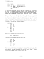
I . INTRODUCTION
The 6809 Mnemonic Assembler is a fast and powerful disk based assembler
interfaced to the FLEXt disk operating system. It accepts all standard
Motorola mnemonics for the 6809 instruction set as well as all standard
6800 and 6801 mnemonics. Macros and conditional assembly are supported
as well as numerous other directives for convenient assembler control.
The assembler executes in two passes and can accept any size file on the
disk so long as sufficient memory is installed to contain the symbol
table. Output is in the form of a binary disk file or a hexadecimal tape
as well as an assembled listing output which may be routed to a printer
or to a disk file through the facilities of FLEX.
This manual is by no means intended to teach the reader assembly
language programming nor even the full details of the 6809 instruction
set. It assumes the user has a working knowledge of assembly language
programming and a manual describing the 6809 instruction set and
addressing modes in full. The former can be acquired through any of a
large number of books available on assembly programming, the latter from
the 6809 hardware manufacturer or seller.
Throughout the manual a couple of notational conventions are used which
are explained here. The first is the use of angle brackets (’<’ and
’>’). These are often used to enclose the description of a particular
item. This item might be anything from a filename to a macro parameter.
It is enclosed in angle brackets to show that it is a single item even
though the description may require several words. The second notation
is the use of square brackets (’[’ and ’]’). These are used to enclose
an optional item.
FLEX is a trademark of Technical Systems Consultants, Inc.
- 1 -
TSC 6809 Assembler
II.A GETTING THE SYSTEM STARTED
The disk version of the 6809 Mnemonic Asssembler is very simple to use.
There are no built-in editing functions - you must have a previously
edited source file on disk before using the assembler.
This file must
be a standard FLEX text file which is simply textual lines terminated by
a carriage return.
There should be no line numbers or control
characters (except for the carriage returns) in the file. When you have
both the assembler and the edited source file on a disk or disks which
are inserted in a powered up system, you are ready to begin.
The Command Line
The very minimum command line necessary to execute
follows:
an
assembly
is
as
+++ASMB,<filename>
The three plus signs are FLEX’s ready prompt, ASMB is the name of the
assembler file (it has a .CMD extension), and the <filename> is the
standard FLEX specification for the source file you wish to assemble.
The <filename> defaults to a .TXT extension and to the assigned working
drive if an explicit extension and drive number are not given. In this
and forthcoming example command lines, a comma is used to separate
items. It is also possible to use a space or spaces in this capacity.
As stated, this is the very minimum command which can be used.
It is
possible to supply many more parameters or options to the assembler, but
if left off as in this example, the assembler will assume default
parameters. Perhaps the most important options available are the two
associated with output. We say two because there are two types of
output available from the assembler: object code output and assembled
source listing output.
The options regarding the assembled source
listing output will be described a little later.
The object code can be in the form of a binary disk file, a hex output
to tape, or no object code output at all. Since no specifications are
made concerning object code output in the above example, the assembler
will assume the default case which is a binary disk file. Since no name
was specified, the output binary file will assume the same name as the
input source file specified but with a .BIN extension. If such a file
already exists, you will be asked:
DELETE OLD BINARY (Y-N)?
- 2 -
TSC 6809 Assembler
to which you may respond ’Y’ which will delete the existing file and
continue to create the new file or ’N’ which will immediately terminate
the assembly, returning to FLEX with the old binary file remaining
intact.
If you wish to create a binary file by another name or extension, you
may do so by placing the desired file specification on the command line
as follows:
+++ASMB,<input file spec>,<binary file spec>
This binary file specification will default to a .BIN extension and to
the assigned working drive. If a file by that name already exists on
the specified drive, you will be prompted as described above.
Specifying Assembly Options
Now we shall go one step further and add a set of single
option flags which may be set on the command line as follows:
character
+++ASMB,<input file spec>[,<binary file spec>][,+<option list>]
The square brackets indicate that the binary file spec and the option
list are optional. The plus sign is required to separate the option
list from the file specifications. The <option list> is a set of single
character flags which either enable or disable a particular option. In
all cases they reverse the sense of the particular option from its
default sense. There may be any number of options specified and they
may be specified in any order.
There may not be spaces within the
option list. Following is a list of the available options and what they
represent:
B
Do not create a binary file on the disk. No binary file will be
created even if a binary file name is specified. This is useful
when assembling a program to check for errors before the final
program is completed or when obtaining a printed source listing.
L
Suppress the assembled listing output.
If not specified, the
assembler will output each line as it is assembled in pass 2,
Those lines containing errors will always be printed regardless of
whether or not this option is specified.
S
Suppress the symbol table output. The assembler normally prints
out a sorted symbol table at the end of an assembly. This option
suppresses that output. Note that the L option will not suppress
the symbol table output, just the source itself.
- 3 -
TSC 6809 Assembler
G
Turns off printing of multiple line object code instructions.
Certain directives (FCB, FDB, and FCC) can produce several lines
of output listing for only one instruction line. This option
prints the first line of output from such an instruction (the line
which contains the source) but suppresses the printing of the
subsequent lines which contain only object code information.
N
Enables the printing of decimal line numbers on each output line.
These numbers are the consecutive number of the line as read by
the assembler. Error lines are always output with the line number
regardless of the start of this option.
T
Produce a hex output directly to tape. This output is formatted
in the standard Motorola ’S1-S9’ format. Consult the section on
object code production for further details.
Y
This option overrides the prompt for deleting an existing binary
file. In other words, if the Y option (stands for YES) is
specified, an existing binary file of the same name as the one to
be created will be automatically deleted without a prompt.
D
Suppress printing of the date in the header at the top of each
output page.
The assembler normally picks up the current date
from FLEX and prints it in the header.
This option causes the
date to be omitted.
W
Suppress warning messages.
The 6809 assembler is capable of
reporting a number of warning messages as well as an indicator of
long jumps and branches that could be shortened.
This option
suppresses the printing of these messages and indicators.
P<no> This option allows the programmer to specify a page number at
which to start printing of the assembled listing. Complete
instructions can be found in the next paragraph.
Specifying a Starting Page Number
As mentioned in the ’P’ option above, it is possible to specify a
particular page number at which printing of the assembled listing should
commence. All output before that page is suppressed INCLUDING ERROR
LINES! When the specified page is hit, printing begins and continues to
the end of the assembly. Note that it is possible to suspend or to
completely terminate an assembly during output by use of the escape or
escape/return sequence found in FLEX.
The desired page number is
specified right with the ’P’ option in the option list. It must
directly follow the ’P’ and should be a decimal number from 1 to 65,536.
The page number itself must be directly followed by a non-alphanumeric
character (terminator) such as a comma or space. This implies that the
’P’ option, if specified, MUST BE THE LAST OPTION SPECIFIED. The page
number may also be followed or terminated by a plus sign as used in the
following paragraph.
It is also important to note that the PAG mode
must be selected (pagination turned on) in order for the ’P’ option to
have any effect.
The PAG mode may be turned on as described in the
section on Standard Directives.
- 4 -
TSC 6809 Assembler
COMMAND LINE PARAMETERS
The assembler has a facility for passing information from the command
line directly into the source program. A maximum of three pieces of
information or "command line parameters" may be passed to the program.
These parameter are simply strings of characters that
will
be
substituted into the source listing as it is read in by the assembler.
These parameters are expressed in the command line in the manner shown
here:
+++ASMB,<in file>,<binary file>,+<options>,+<prm.l>,<prm.2>,<prm.3>
The parameters are optional but must be separated from the rest of the
line by the second plus sign and from each other by commas. As stated,
these parameters are simply strings of characters. They may be supplied
in two ways: as a string of characters enclosed by a delimiter or just a
string
of
characters
with no spaces or commas embedded.
The
"delimiters" which can be used to enclose a string are the single quote
(’) and the double quote ("). Either can be used but for a particular
string the beginning delimiter and the ending delimiter must be the
same. The reason for using a delimited string is to pass in a string
with commas and/or spaces which cannot be in an un-delimited string.
Note that if one wishes to enter a command line parameter but no
options, he must still place both plus signs in the command as seen in
this example command line:
+++ASMB,ANYFILE,++PARAMETER1,PARAMETER2
For further information on command line parameters and how to specify
where in the source program these parameters should be substituted, see
the section on Special Features.
OUTPUTTING TO A HARDCOPY DEVICE
The assembler does not have a built in means for outputting the
assembled listing to a hardcopy device.
This operation is, however,
available through the facilities of FLEX. To do so one must use the ’P’
command provided with FLEX. This ’P’ command reads a printer driver
file which you can supply to output to any hardcopy device you want. It
effectively switches the output of the assembler from going to the
terminal to going to the printer. For example:
+++P,ASMB,TESTFILE
would cause the assembled listing of the source file TESTFILE.TXT to be
output to the printer. For further details of use of the ’P’ command
the FLEX User’s Manual and Advanced Programmer’s Guide.
- 5 -
TSC 6809 Assembler
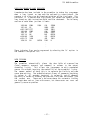
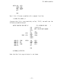
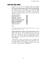
EXAMPLES:
ASMB,TEST
Assembles a file called TEST-TXT on the assigned working drive
and creates a binary file called TEST.BIN on the same drive.
The assembled listing is output to the terminal as is the
symbol table.
ASMB,TEST,+LS
Same as before except that no listing is output (except for
any lines with errors) and no symbol table is output.
ASMB,0.TEST,1.TEST.CMD,+LSY
Assembles a file from drive 0 called TEST.TXT and produces a
binary file on drive 1 called TEST.CMD. No listing or symbol
table is output and if a file by the name of TEST.CMD already
resides on drive 1, it will be automatically deleted before
the assembly starts.
l.ASMB,0.TEST.BAK,+BNGS
Loads the assembler itself from drive 1 and assembles a file
called TEST.BAK found on drive 0. No binary file is produced.
The assembled listing is output with line numbers turned on
and multiple line generated code turned off. No symbol table
is printed.
ASMB,0.TEST.BAK,+GSBNP26
This command performs just like the last with two exceptions.
First, the assembler itself is loaded from the whatever the
assigned system drive is.
Second, the assembled listing
output does not begin until the assembler reaches page number
26.
0.ASMB,0.ASMB,0.ASMB,+GW,+MINI,’ASSEMBLER FOR 5" DISK’
This command looks a little confusing, but it was done to
accentuate the method in which default extensions work. The
assembler itself (a file called ASMB.CMD) is loaded from drive
0, the file called ASMB.TXT found on drive 0 is assembled, and
a binary file is produced on drive 0 by the name ASMB.BIN.
Note that it was not necessary to specify the binary file name
in this case since ASMB.BIN is what the default would have
been. The assembled listing is output with multiple line code
generation suppressed and warning messages suppressed.
There
are two parameters which may be passed into the source
listing. The first is the single word ’MINI’.
The second
parameter is the entire string, ’ASSEMBLER FOR 5" DISK’,
excluding the single quote delimiters (everything starting
with the A and ending with the K).
- 6 -
TSC 6809 Assembler
III.
ASSEMBLER OPERATION & SOURCE LINE COMPONENTS
The TSC Assembler is a 2 pass assembler. During pass one a symbolic
reference table is constructed and in pass two the code is actually
assembled, printing a listing and outputting object code if desired.
The source may be supplied in free format as described below. Each line
of source consists of the actual source statement terminated with a
carriage return (0D hex).
The source must be comprised of ASCII
characters with their parity or 8th bit cleared to zero.
Special
meaning is attached to many of these characters as will be described
later. Control characters (00 to FF hex) other than the carriage return
(0DH) are prohibited from being in the actual source statement part of
the line.
Their inclusion in the source statement will produce
undefined results. Each source line is comprised of up to four fields:
Label, Opcode, Operand, and Comment. With two exceptions, every line
must have an opcode while the other fields may or may not be optional.
These two exceptions are:
1) "Comment Lines" may be inserted anywhere in the source and are
ignored by the assembler during object code production.
Comment lines may be either of two types:
a) Any line beginning with an asterisk (hex 2A) in column
one.
b) A null line or a line containing only a carriage return.
While this line can contain no text, it is still
considered a comment line as it causes a space in the
output listing.
2) lines which contain a label but no opcode or operand field.
- 7 -
TSC 6809 Assembler
SOURCE STATEMENT FIELDS
The
four
fields
are
described
here along with their format
specifications. The fields are free format which means there may be any
number of spaces separating each field.
In general, no spaces are
allowed within a field.
LABEL OR SYMBOL FIELD:
This field may contain a symbolic label or name which is assigned the
instruction’s address and may be called upon throughout the source
program.
1) The label must begin in column one and must be unique. Labels
are optional. If the label is to be omitted, the first
character of the line must be a space.
2) A label may consist of letters (A-Z or a-z), numbers (0-9), or
an underscore (_ or 5F hex). Note that upper and lower case
letters are not considered equivalent. Thus ’ABC’ is a
different label from ’Abc’.
3) Every label must begin with a letter.
4) Labels may be of any length, but only the first 6 characters
are significant.
5) The label field must be terminated by a space or a return.
OPCODE FIELD:
This field contains the 6809 opcode (mnemonic) or pseudo-op. It
specifies the operation that is to be performed.
The pseudo-ops
recognized by this assembler are described later in this manual.
1) The opcode is made up of letters (A-Z or a-z) and numbers
(0-9). In this field, upper and lower case may be used
interchangeably.
2) This field must be terminated by a space if there is an
operand or by a space or return if there is no operand.
OPERAND FIELD:
The operand provides any data or address information which may be
required by the opcode.
This field may or may not be required,
depending on the opcode.
Operands are generally combinations of
register specifications and mathematical expressions which can include
constants, symbols, ASCII literals, etc. as explained later.
- 8 -
TSC 6809 Assembler
1) The operand field can contain no spaces.
2) This field is terminated with a space or return.
3) Any of several types of data may make up the operand: register
specifications, numeric constants, symbols, ASCII literals,
and the special PC designator.
COMMENT FIELD:
The comment field may be used to insert comments on each line of source.
Comments are for the programmer’s convenience only and are ignored by
the assembler.
1) The comment field is always optional.
2) This field must be preceded by a space.
3) Comments may contain any characters from SPACE (hex 20) thru
DELETE (hex 7F).
4) This field is terminated by a carriage return.
REGISTER SPECIFICATION
Many opcodes require that the operand following them specify one or more
registers. EXG and TFR require two registers specified, push and pull
allow any number, and the indexed addressing mode requires specification
of the register by which indexing is to be done.
The following are
possible register names:
A,B,CC,DP,X,Y,U,S,D,PC
The EXG and TFR instructions require two register specs separated by a
comma. The push and pull instructions allow any number of registers to
be specified, again, separated by commas. Indexed addressing requires
one of X,Y,U, or S as explained under the indexed addressing mode
description.
EXPRESSIONS
Many opcodes require that the operand supply further data or information
in the form of an expression. This expression may be one or more items
combined by any of four operator types: arithmetic, logical, relational,
and shift.
- 9 -
TSC 6809 Assembler
Expressions are always evaluated as full 16 bit operations. If the
result of the operation is to be only 8 bits, the assembler truncates
the upper half.
If truncation occurs when warnings are enabled, an
appropriate message will be issued.
No spaces may be imbedded in an expression.
ITEM TYPES:
The "item or items" used in an expression may be any of four types as
listed below. These may stand alone or may be intermixed by the use of
the operators.
1) NUMERICAL CONSTANTS: Numbers may be supplied to the assembler
in any of the four number bases shown below. The number given
will be converted to 16 bits truncating any numbers greater
than that.
If 8 bit numbers are required, the 16 bit number
will then be further truncated to 8 bits with notification of
such if warning messages are enabled. To specify which number
base is desired, the programmer must supply a prefix character
to a number as detailed below.
BASE
PREFIX
CHARACTERS ALLOWED
Decimal
Binary
Octal
Hexadecimal
none
%
@
$
0
0
0
0
thru 9
or 1
thru 7
thru 9, A thru F
If no prefix is assigned, the assembler assumes the number to
be decimal.
2) ASCII CONSTANTS:
The binary equivalent of a single ASCII
printable character may be supplied to the assembler by
preceding it with a single quote. The character should be
between 20 and 7F hex.
3) LABELS:
Labels which have been assigned some address or
constant value may be used in expressions. As described above
under the label field, a label is comprised of letters,
digits, and hyphens beginning with a letter. The label may be
of
any
length,
but only the first 6 characters are
significant. Any label used in the operand field must be
defined elsewhere in the program.
4) PC DESIGNATOR: The asterisk (*) has been set aside as a
special PC designator (Program Counter). It may be used in an
expression just as any other value and is equal to the address
of the current instruction.
- 10 -
TSC 6809 Assembler
EXPRESSION OPERATORS
As mentioned previously, the four classes of operators are: arithmetic,
logical, relational, and shift. These operators permit assembly-time
operations such as addition or division to take place. "Assembly-time"
means that the expression is evaluated during the assembly and the
result becomes a permanent part of your program.
a) ARITHMETIC OPERATORS
The arithmetic operators are as follows:
Operator
+
*
/
Meaning
Unary or binary addition
Unary or binary subtraction
Multiplication
Division (any remainder is discarded)
b) LOGICAL OPERATORS
The logical operators are as follows:
Operator
&
|
!
>>
<<
Meaning
logical AND operator
Logical OR operator
Logical NOT operator
Shift right operator
Shift left operator
The logical operations are full 16 bit operations.
In other words for the AND operation, every bit from
the first operand or item is individually AND’ed with
its corresponding bit from the second operand or item.
The shift operators shift the left term the number of
places indicated by the right term. Zeroes are
shifted in and bits shifted out are lost.
c) RELATIONAL OPERATORS
The relational operators are as follows:
Operator
=
<
>
<>
<=
>=
Meaning
Equal
Less than
Greater than
Not equal
Less than or equal
Greater than or equal
The relational operations yield a true-false result.
If the evaluation of the relation is true, the resulting
value be all ones.
If false, the resulting value will
will be all zeros. Relational operations are generally
used in conjunction with conditional assembly as shown
in that section.
- 11 -
TSC 6809 Assembler
OPERATOR PRECEDENCE
Certain operators take precedence over others in an expression. This
precedence can be overcome by use of parentheses. If there is more than
one operator of the same priority level and no parentheses to indicate
the order in which they should be evaluated, then the operations are
carried out in a left to right order.
The following list classifies
(highest priority first):
1)
2)
3)
4)
5)
6)
7)
8)
the
operators
Parenthesized expressions
Unary + and Shift operators
Multiply and Divide
Binary Addition and Subtraction
Relational Operators
Logical NOT Operator
Logical AND and OR Operators
in
- 12 -
order
of
precedence
TSC 6809 Assembler
IV.
The INSTRUCTION SET
This section is a quick introduction to the 6809 architecture and
insruction set. It is by no means complete.
The intention is to
familiarize the user who is already proficient at 6800 assembly language
programming with the basic structure of 6809 assembly language. For
more complete details on the 6809 instruction set you should obtain the
proper documentation from the hardware manufacturer.
PROGRAMMING MODEL
The 6809 microprocessor has 9 registers that are accessible by the
programmer. Four of these are 8-bit registers while the other five are
16-bit registers. Two of the 8-bit registers can, in some instances, be
referenced as one 16-bit registers. The registers are as follows:
The
The
The
The
The
The
The
The
The
’A’ accumulator (A)
’B’ accumulator (B)
Condition Code register (CC)
Direct Page register (DP)
’X’ index register (X)
’Y’ index register (Y)
User stack pointer (U)
System stack pointer (5)
Program Counter (PC)
8
8
8
8
16
16
16
16
16
bit
bit
bit
bit
bit
bit
bit
bit
bit
The A and B accumulators can often be referenced as one 16-bit register
represented by a ’D’ (for Double-accumulator). In these cases, the A
accumulator is the most significant half.
THE ADDRESSING MODES
There are several possible addressing modes in the 6809 instruction set.
One of the best features of the 6809 is the consistency or regularity
built into the instruction set. For the most part, any instruction
which addresses memory can use any of the addressing modes available.
It is not necessary to remember which instructions can use which
addressing modes, etc. The addressing modes and a brief description of
each follow.
1)
Inherent
Inherent addressing refers to those instructions
addressing associated with them.
Example: ABX
add B accumulator to X
- 13 -
which
have
no
TSC 6809 Assembler
2)
Accumulator
Accumulator addressing is done in those instructions which can
specify the A or B accumulator. In some cases this may be the
16-bit D accumulator.
Example: DECA
decrement the A accumulator
3)
Immediate
In Immediate addressing the byte or bytes following the opcode are
the information being addressed. These byte or bytes are specified
as part of the instruction.
Example: LDA #8
load immediate value (8) into A
4)
Relative - Long and Short
In Relative addressing, the value of the byte(s) immediately
following the opcode (1 if short, 2 if long) are added as a two’s
complement number to the current value of the program counter (PC
register) to produce a new PC location. In the source code, the
programmer specifies the desired address to which execution should
be transferred and the assembler determines the correct offset to
place after the opcode.
Example: LBRA THERE the program will branch to THERE
5)
Extended
In Extended addressing, the two bytes (16-bits) following the opcode
are used as an absolute memory address value.
Example: LDA $1000 load A from memory location 1000 hex
6)
Direct
In Direct addressing, the single byte (8-bits) following the opcode
is used as a pointer into a 256-byte window or "page" of memory.
The page used for this purpose is the one currently found in the
Direct
Page
register.
Thus,
the
effective address is a
concatenation of the Direct Page register as the most significant
half and the byte following the opcode as the least significant
half.
Example: LDA $22 load A from memory location $XX22 where XX
represents the contents of the DP register
7)
Extended Indirect
In Extended Indirect addressing, the 16-bit value following the
opcode is used to point to two bytes in memory which are used as the
effective address.
Example: LDA [$A012] loads A from the address stored at
locations $A012 and $A013
- 14 -
TSC 6809 Assembler
8)
Indexed
The Indexed addressing mode of the 6809 is an extremely powerful
method of specifying addresses which is, in general, some sort of
offset from the value stored in one of the registers X, Y, U, S, or
PC.
There are several forms of indexed addressing which could each
be considered an addressing mode in itself.
We will, however,
discuss each as a subset of Indexed addressing in general. Note
that except for the Auto-increment and Auto-decrement
modes,
determining the effective address has no effect on the register
being used as the index.
8a) Constant-Offset Indexed
This mode uses a two’s complement offset value found in the byte or
bytes following the opcode. The offset is added to the contents of
the specified register to produce a 16-bit effective address. The
offset may be represented as a number, a symbol, or any valid
expression. It can be either positive or negative and can be a full
16-bits.
Example: LDA 0,X loads A from location pointed to by X
LDA 5216,Y loads A from (Y) plus 5216
LDA -36,U loads A from (U) minus 36
LDA VAL,S loads A from (S) plus VAL
8b) Accumulator Indexed
In Accumulator indexing, the contents of the specified accumulator
(A, B, or D) are added to the specified indexing register as a two’s
complement value. The result is the effective address.
Example: LDA B,Y loads A from (B)+(Y)
LDX D,S loads X from (D)+(S)
8c) Auto-Increment
The contents of the selected register are used as the effective
address with no offset permitted. After that effective address has
been determined, the selected register is incremented by one (for
single plus sign) or two (double plus sign).
Example: LDA 0,X+ loads A from X then bumps X by 1
LDD ,Y++ loads D from Y then bumps Y by 2
8d) Auto-Decrement
In auto-decrementing, the selected register is first decremented by
one (single minus sign) or two (double minus sign). The resulting
value, with no offset, is used as the effective address.
Example: LDA 0,-U decrements U by 1 then loads A from address in U
LDU ,--S decrements S by 2 then loads U from address in S
- 15 -
TSC 6809 Assembler
FURTHER ADDRESSING MODES
Indexed Indirect Addressing
All the Indexed Addressing modes above can also be used in an indirect
fashion by enclosing the operand in square brackets. When this is done,
the effective address as described in all the above modes is no longer
the final effective address. Instead, the two bytes pointed to by that
address are used as the effective address.
Examples: LDA [,X] loads A from the address pointed to by X
LDX [D,U] loads X from the address pointed
to by (U)+(D)
If auto-increment or auto-decrement addressing is done in an indirect
fashion, they must be a double increment (two plus signs) or double
decrement (two minus signs).
PC Relative Addressing
Indexing may be done from the PC register just as from the X, Y, U, or
S. The general use of indexing from the PC register is to address some
value in a position-independent manner. Thus if we address some value
at the current PC plus 10, no matter where the program executes the
value will always be addressed. The programmer does not usually know
what that constant offset should be, he knows the address of the value
he wants to access as an absolute value for the program as assembled.
Thus a mechanism has been included in the assembler to automatically
determine the offset from the current PC to that absolute address. This
mechanism is called PC Relative Addressing. The value specified in a PC
Relative address operand is the absolute value. The assembler takes the
difference between this absolute value and the current PC and generates
that offset as part of the assembled code for the instruction. PC
Relative Addressing is distinguished from normal PC Offset Indexing by
the use of ’PCR’ as the register name instead of ’PC’.
Example:
LEAX STRING,PCR
this instruction determines the offset
between the PC and STRING and uses it
as an offset for the PC register to
determine the effective address
- 16 -
TSC 6809 Assembler
FORCING DIRECT OR EXTENDED ADDRESSING
The 6809 assembler has a mechanism for forcing the assembler to perform
either direct or extended addressing.
Under normal conditions, the
assembler will use direct addressing when possible.
To force the
assembler to use extended addressing no matter what the conditions,
simply precede the operand with a greater than sign (’>’). For example,
suppose the DP register was set to $00 (this is the default on reset of
the cpu), and that we have a label, BUFPNT, which is at memory location
$0010. Normally the instruction:
LDX BUFPNT
would be assembled with direct addressing.
extended addressing we could simply enter:
If
we wished to force
LDX >BUFPNT
and the assembler would use extended addressing.
The same capability exists for forcing direct addressing by preceding
the operand with a less than sign (’<’). For example:
LDX <BUFPNT
would force direct addressing. Note that in both cases the greater than
or less than sign must be the first character in the operand.
- 17 -
TSC 6809 Assembler
THE ASSEMBLER INSTRUCTION SET
This section contains a brief listing of all the mnemonics accepted by
the 6809 assembler. They are listed in four sections, standard 6809
with alternate 6800, 6800 mnemonics not found in 6809, 6801 mnemonics,
and non-standard convenience mnemonics. Before the listing, we must
setup some notational conventions:
(P)
Operand containing immediate, extended, direct, or
indexed addressing.
(Q)
Operand containing extended, direct, or indexed
addressing.
(T)
Operand containing indexed addressing only.
R
Any register specification: A, B, X, Y, U, S, PC,
CC, DP, or D.
dd
8 bit data value
dddd
16 bit data value
6809 MNEMONICS WITH 6800 ALTERNATES
ABX
Add B into X
SOURCE FORM: ABX
ADC
Add with carry into register
SOURCE FORM: ADCA (P); ADCB (P)
6800 ALTERNATES: ADC A (P); ADC B (P)
ADD
Add into register
SOURCE FORM: ADDA (P); ADDB (P); ADDD (P)
6800 ALTERNATES: ADD A (P); ADD B (P)
AND
Logical ’AND’ into register
SOURCE FORM: ANDA (P); ANDB (P)
6800 ALTERNATES: AND A (P); AND B (P)
ANDCC
Logical ’AND’ immediate into CC
SOURCE FORM: ANDCC #dd
ASL
Arithmetic shift left
SOURCE FORM: ASLA; ASLB; ASL (Q)
6800 ALTERNATES: ASL A; ASL B
- 18 -
TSC 6809 Assembler
ASR
Arithmetic shift right
SOURCE FORM: ASRA; ASRB; ASR (Q)
6800 ALTERNATES: ASR A; ASR B
BCC, LBCC
Branch (short or long) if carry clear
SOURCE FORM: BCC dd; LBCC dddd
BCS, LBCS
Branch (short or long) if carry set
SOURCE FORM: BCS dd; LBCS dddd
BEQ, LBEQ
Branch (short or long) if equal
SOURCE FORM: BEQ dd; LBEQ dddd
BGE, LBGE
Branch (short or long) if greater than or equal
SOURCE FORM: BGE dd; LBGE dddd
BGT, LBGT
Branch (short or long) if greater than
SOURCE FORM: BGT dd; LBGT dddd
BHI, LBHI
Branch (short or long) if higher
SOURCE FORM: BHI dd; LBHI dddd
BHS, LBHS
Branch (short or long) if higher or same
SOURCE FORM: BHS dd; LBHS dddd
BIT
Bit test
SOURCE FORM: BITA (P); BITB (P)
6800 ALTERNATES: BIT A (P); BIT B (P)
BLE, LBLE
Branch (short or long) if less than or equal to
SOURCE FORM: BLE dd; LBLE dddd
BLO, LBLO
Branch (short or long) if lower
SOURCE FORM: BLO dd; LBLO dddd
BLS, LBLS
Branch (short or long) if lower or same
SOURCE FORM: BLS dd; LBLS dddd
BLT, LBLT
Branch (short or long) if less than
SOURCE FORM: BLT dd; LBLT dddd
BMI, LBMI
Branch (short or long) if minus
SOURCE FORM: BMI dd; LBMI dddd
BNE, LBNE
Branch (short or long) if not equal
SOURCE FORM: BNE dd; LBNE dddd
BPL, LBPL
Branch (short or long) if plus
SOURCE FORM: BPL dd; LBPL dddd
- 19 -
TSC 6809 Assembler
BRA, LBRA
Branch (short or long) always
SOURCE FORM: BRA dd; LBRA dddd
BRN, LBRN
Branch (short or long) never
SOURCE FORM: BRN dd; LBRN dddd
BSR, LBSR
Branch (short or long) to subroutine
SOURCE FORM: BSR dd; LBSR dddd
BVC, LBVC
Branch (short or long) if overflow clear
SOURCE FORM: BVC dd; LBVC dddd
BVS, LBVS
Branch (short or long) if overflow set
SOURCE FORM: BVS dd; LBVS dddd
CLR
Clear
SOURCE FORM: CLRA; CLRB; CLR (Q)
6800 ALTERNATES: CLR A; CLR B
CMP
Compare
SOURCE FORM: CMPA (P); CMPB (P); CMPD (P); CMPX (P);
CMPY (P); CMPU (P); CMPS (P)
6800 ALTERNATES: CMP A (P); CMP B (P); CPX (P)
COM
Complement (One’s complement)
SOURCE FORM: COMA; COMB; COM (Q)
6800 ALTERNATES: COM A; COM B
CWAI
Clear and wait for interrupt
SOURCE FORM: CWAI #dd
DAA
Decimal adjust accumulator A
SOURCE FORM: DAA
DEC
Decrement
SOURCE FORM: DECA, DECB, DEC (Q)
6800 ALTERNATES: DEC A; DEC B
EOR
Exclusive ’OR’
SOURCE FORM: EORA (P); EORB (P)
6800 ALTERNATES: EOR A (P); EOR B (P)
EXG
Exchange registers
SOURCE FORM: EXG Rl,R2
INC
Increment
SOURCE FORM: INCA, INCB, INC (Q)
6800 ALTERNATES: INC A; INC B
- 20 -
TSC 6809 Assembler
JMP
Jump to address
SOURCE FORM: JMP dddd
JSR
Jump to subroutine at address
SOURCE FORM: JSR dddd
LD
Load register from memory
SOURCE FORM: LDA (P); LDB (P); LDD (P); LDX (P);
LDY (P); LDU (P); LDS (P)
6800 ALTERNATES: LDAA (P); LDAB (P); LDA A (P); LDA B (P)
LEA
Load effective address
SOURCE FORM: LEAX (T); LEAY (T); LEAU (T); LEAS (T)
LSL
Logical shift left
SOURCE FORM: LSLA; LSLB; LSL (Q)
LSR
Logical shift right
SOURCE FORM: LSRA; LSRB; LSR (Q)
6800 ALTERNATES: LSR A; LSR B
MUL
Multiply accumulators
SOURCE FORM: MUL
NEG
Negate (Two’s complement)
SOURCE FORM: NEGA; NEGB; NEG (Q)
6800 ALTERNATES: NEG A; NEG B
NOP
No operation
SOURCE FORM: NOP
OR
Inclusive ’OR’ into register
SOURCE FORM: ORA (P); ORB (P)
6800 ALTERNATES: ORAA (P); ORAB (P); ORA A (P); ORA B (P)
ORCC
Inclusive ’OR’ immediate into CC
SOURCE FORM: ORCC #dd
PSHS
Push registers onto system stack
SOURCE FORM: PSHS (register list); PSHS #dd
6800 ALTERNATES: PSRA; PSHB; PSH A; PSH B
PSHU
Push registers onto user stack
SOURCE FORM: PSHU (register list); PSHU #dd
PULS
Pull registers from system stack
SOURCE FORM: PULS (register list); PULS #dd
6800 ALTERNATES: PULA; PULB; PUL A; PUL B
PULU
Pull registers from user stack
SOURCE FORM: PULU (register list); PULU #dd
- 21 -
TSC 6809 Assembler
ROL
Rotate left
SOURCE FORM: ROLA; ROLB; ROL (Q)
6800 ALTERNATES: ROL A; ROL B
ROR
Rotate right
SOURCE FORM: RORA; RORB; ROR (Q)
6800 ALTERNATES: ROR A; ROR B
RTI
Return from interrupt
SOURCE FORM: RTI
RTS
Return from subroutine
SOURCE FORM: RTS
SBC
Subtract with borrow
SOURCE FORM: SBCA (P); SBCB (P);
6800 ALTERNATES: SBC A (P); SBC B (P)
SEX
Sign extend
SOURCE FORM: SEX
ST
Store register into memory
SOURCE FORM: STA (P); STB (P); STD (P); STX (P);
STY (P); STU (P); STS (P)
6800 ALTERNATES: STAA (P); STAB (P); STA A (P); STA B (P)
SUB
Subtract from register
SOURCE FORM: SUBA (P); SUBB (P); SUBD (P)
6800 ALTERNATES: SUB A (P); SUB B, (P)
SWI
Software interrupt
SOURCE FORM: SWI
SWI2
Software interrupt 2
SOURCE FORM: SWI2
SWI3
Software interrupt 3
SOURCE FORM: SWI3
SYNC
Synchronize to interrupt
SOURCE FORM: SYNC
TFR
Transfer register to register
SOURCE FORM: TFR Rl,R2
TST
Test
SOURCE FORM: TSTA; TSTB; TST (Q)
6800 ALTERNATES: TST A; TST B
- 22 -
TSC 6809 Assembler
SIMULATED 6800 INSTRUCTIONS
ABA
Add B to A
CBA
Compare B to A
CLC
Clear carry bit
CLI
Clear interrupt mask
CLV
Clear overflow bit
DES
Decrement stack pointer
DEX
Decrement X
INS
Increment stack pointer
INX
Increment X
SBA
Subtract B from A
SEC
Set carry bit
SEI
Set interrupt mask
SEV
Set overflow bit
TAB
Transfer A to B
TAP
Transfer A to CC
TBA
Transfer B to A
TPA
Transfer CC to A
TSX
Transfer S to X
TXS
Transfer X to S
WAI
Wait for interrupt
- 23 -
TSC 6809 Assembler
SIMULATED 6801 MNEMONICS
ASLD
Arithmetic shift left D
LSRD
Logical shift right D
PSHX
Push the X register
PULX
Pull the X register
LDAD
Load accumulator D from memory
STAD
Store accumulator D into memory
CONVENIENCE MNEMONICS
BEC,LBEC
Branch (short or long) if error clear
BES,LBES
Branch (short or long) if error set
CLF
Clear FIRQ interrupt mask
CLZ
Clear zero condition code bit
SEF
Set FIRQ interrupt mask
SEZ
Set zero condition code bit
- 24 -
TSC 6809 Assembler
V. STANDARD DIRECTIVES OR PSEUDO-OPS
Besides the standard machine language mnemonics, the TSC assembler
supports several directives or pseudo-ops. These are instructions for
the assembler to perform certain operations, and are not directly
assembled into code. There are three types of directives in this
assembler,
those
associated
with macros, those associated with
conditional assembly, and those which generally can be used anywhere
which we shall call "standard directives". This section is devoted to
descriptions of these directives which are briefly listed here:
ORG
END
RMB
FCB
FDB
FCC
EQU
SET
REG
SETDP
PAG
SPC
NAM or TTL
STTL
ERR
RPT
LIB
OPT
Descriptions of each directive and its use follow.
ORG
The ORG statement is used to set a new code ’Origin’. This simply means
that a new address is set into the location Counter (or program counter)
so that subsequent code will be placed at the new location. The form is
as follows:
ORG <expression>
No label may be placed on an ORG statement and no code is produced. If
no ORG statement appears in the source, an origin of 0000 is assumed.
END
The END pseudo-op is used to signal the assembler that the end of the
source input has occurred. This terminates whatever pass is currently
being executed. No label is allowed and no code is generated. An
expression may be given (as shown below) as the transfer address to be
placed in a binary file. It is optional, and if supplied when no binary
file is being produced, will be ignored.
END
[<expression>]
Note that an end statement is not strictly required, but is the only
means of getting a transfer address appended to a binary output file.
- 25 -
TSC 6809 Assembler
RMB
The RMB or Reserve Memory Bytes directive is used to reserve areas of
memory for data storage.
The number of bytes specified by the
expression in the operand are skipped during assembly. No code is
produced in those memory location and therefore the contents are
undefined at run time. The proper useage is shown here:
[<label>] RMB <expression>
The label is optional, and the expression is a 16 bit quantity.
FCB
The FCB or Form Constant Byte directive is used to set associated memory
bytes to some value as determined by the operand. FCB may be used to
set any number of bytes as shown below:
[<label>] FCB <expr. 1>,<expr. 2>,....<expr. n>
Where <expr. x> stands for some expression.
Each expression given
(separated by commas) is evaluated to 8 bits and the resulting
quantities are stored in successive memory locations. The label is
optional.
FDB
The FDB or Form Double Byte directive is used to setup 16 bit quantities
in memory.
It is exactly like the FCB directive except that 16 bit
quantities are evaluated and stored in memory for each expression given.
The form of the statement is:
[<label>] FDB <expr. 1>,<expr. 2>,...,<expr. n>
Again, the label field is optional.
FCC
The FCC or Form Constant Character directive allows the programmer to
specify a string of ASCII characters delimited by some non-alphanumeric
character such as a single quote. All the characters in the string will
be converted to their respective ASCII values and stored in memory, one
byte per character. Some valid examples follow:
LABEL1 FCC ’THIS IS AN FCC STRING’
LABEL2 FCC .SO IS THIS.
FCC /LABELS ARE NOT REQUIRED./
- 26 -
TSC 6809 Assembler
There is another method of using FCC which is a deviation from the
standard Motorola definition of this directive. This allows you to
place certain expressions on the same line as the standard FCC delimited
string.
The items are separated by commas and are evaluated to 8 bit
results. In some respects this is like the FCB directive. The
difference is that in the FCC directive, expressions must begin with a
letter, number or dollar-sign whereas in the FCB directive any valid
expression will work.
For example, %10101111 would be a valid
expression for an FCB but not for an FCC since the percent-sign would
look like a delimiter and the assembler would attempt to produce 8 bytes
of data from the 8 ASCII characters which follow (an FCC string). The
dollar-sign is an exception to allow hex values such as $0D (carriage
return) to be inserted along with strings. Some examples follow:
INTRO
FCC
FCC
FCC
’THIS STRING HAS CR & LF’,$D,$A
’STRING 1’,0,’STRING 2’
$04,LABEL,/DELIMITED STRING/
Note that more than one delimited string may be placed on a line
the second example.
as
in
EQU
The EQU or Equate directive is used to equate a symbol to the expression
given in the operand. No code is generated by this statement. Once a
symbol has been equated to some value, it may not be changed at a later
time in the assembly. The form of an equate statement is as follows:
<label>
EQU
<expression>
The label is strictly required in equate statements.
SET
The SET directive is used to set a symbol to the value of some
expression, much as an EQU directive. The difference is that a symbol
may be SET several times within the source (to different values) while a
symbol may be Equated only once. If a symbol is SET to several values
within the source, the current value of the symbol will be the value
last SET. The statement form is:
<label> SET <expression>
The label is strictly required and no code is generated.
- 27 -
TSC 6809 Assembler
REG
The
by
and
REG
REG
REG directive allows the user to setup a list of registers for use
the push and pull instructions. This list is represented by a value
the value is equated to the label supplied. In this respect, the
directive is similar to the EQU directive. The correct form of the
directive is:
<label> REG <register list>
As an example, suppose a program has a large number of occurences of the
following instructions:
PSHS A,B,Y,U,DP
PULS A,B,Y,U,DP
To make things more convenient and less error prone
could be used as shown here:
RLIST2
the
REG
directive
REG A,B,Y,U,DP
Now all the pushes
with the statements:
and pulls referred to above could be accomplished
PSHS #RLIST2
PULS #RLIST2
Of course, the register list may still be typed out on push and pull
instructions or an immediate value (with the desired bit pattern) may be
specified.
SETDP
The SETDP or Set Direct Page directive allows the user to set which
memory page the assembler will use for the direct page addressing mode.
The correct format is as follows:
SETDP [<page value>]
As an example, if "SETDP $D0" is encountered, the assembler will then
use direct addressing for any address in the range of $D000 to $D0FF.
It is important to note that this directive does not actually affect the
contents of the direct page register. The value set is what will be
used at assembly time to determine direct addressing, but it is up to
the user to be sure the DP register corresponds at run time.
If there
is no <page value> supplied, direct addressing will be disabled and all
addresses will be full 16 bit values. Any number of SETDP instructions
may occur in a program.
The default value is page 0 (for 6800
compatibility).
- 28 -
TSC 6809 Assembler
PAG
The PAG directive causes a page eject in the output listing and prints a
header at the top of the new page. Note that the ’PAG’ option must have
been previously selected in order for this directive to take effect. It
is possible to assign a new number to the new page by specifying such in
the operand field. If no page number is specified, the next consecutive
number will be used. No label is allowed and no code is produced. The
PAG operator itself will not appear in the listing unless some sort of
error is encountered. The proper form is:
PAG [<expression>]
Where the expression is optional. The first page of a listing does not
have the header printed on it and is considered to be page 0.
The
intention here is that all options, title, and subtitle may be setup and
followed by a PAG directive to start the assembled listing at the top of
page 1 without the option, title, or subtitle instructions being in the
way.
SPC
The SPC or Space directive causes the specified number of spaces (line
feeds) to be inserted into the output listing. The general form is:
SPC [<space count>[,<keep count>]]
The space count can be any number from 0 to 255. If the page option is
selected, SPC will not cause spacing past the top of a new page.
The
<keep count> is optional and is the number of lines which the user
wishes to keep together on a page. If there are not enough lines left
on the current page, a page eject is performed. If there are <keep
count> lines left on the page (after printing <space count> spaces),
output will continue on the current page.
If the page option is not
selected, the <keep count> will be ignored.
If no operand is given
(ie. just the directive SPC), the assembler will default to one blank
line in the output listing.
TTL OR NAM
The TTL or NAM directive allows the user to specify a title or name to
the program being assembled.. This title is then printed in the header
at the top of each output listing page if the page option is selected.
If the page option is not selected, this directive is ignored. The
proper form is:
TTL <text for the title>
or
NAM <text for the title>
All the text following the TTL or NAM directive (excluding leading
spaces) is placed in the title buffer. Up to 32 characters are allowed
with any excess being ignored. It is possible to have any number of TTL
- 29 -
TSC 6809 Assembler
or NAM directives in a source program. The latest one encountered will
always be the one used for printing at the top of the following page(s).
STTL
The STTL or Subtitle directive is used to specify a subtitle to
printed just below the header at the top of an output listing page.
is specified much as the TTL directive:
be
It
STTL <text for the subtitle>
The subtitle may be up to 52 characters in length. If the page option
is not selected, this directive will be ignored. As with the TTL
option, any number of STTL directives may appear in a source program.
The subtitle can be disabled or turned off by an STTL command with no
text following.
ERR
The ERR directive may be used to insert user-defined error messages in
the output listing. The error count is also bumped by one. The proper
form is:
ERR <message to be printed>
All text past the ERR directive (excluding leading spaces) is printed as
an error message (it will be preceded by three asterisks) in the output
listing. Note that the ERR directive line itself is not printed.
A
common use for the ERR directive is in conjunction with conditional
assembly such that some user-defined illegal condition may be reported
as an error.
RPT
The RPT or Repeat directive causes the succeeding line of source to be
repeated some specified number of times. The syntax is as follows:
RPT
<count>
where <count> may be any
following two lines:
number
from
RPT 4
ASLB
- 30 -
1
to
127.
For
example,
the
TSC 6809 Assembler
would produce an assembled output of:
ASLB
ASLB
ASLB
ASLB
Some directives, such as IF or MACRO, may not be repeated with the RPT
command. These cases are where it is illogical or impractical to do so.
If attempted, the RPT will simply be ignored.
LIB
The LIB or Library directive allows the user to specify an external file
for inclusion in the assembled source output. Under normal conditions,
the assembler reads all input from the file specified on the calling
line. The LIB directive allows the user to temporarily obtain the source
lines from some other file. When all the lines in that external file
have been read and assembled, the assembler resumes reading of the
original source file. The proper syntax is:
LIB <file spec>
where <file spec> is a standard FLEX file specification. The default
drive is the assigned working drive and the default extension is .TXT.
Any END statements found in the file called by the LIB directive are
ignored. The LIB directive line itself does not appear in the output
listing. Any number of LIB instructions may appear in a source listing.
It is also possible to nest LIB files up to 12 levels.
Nesting refers
to the process of placing a LIB directive within the source that is
called up by another LIB directive. In other words, one LIB file may
call another.
OPT
The OPT or Option directive allows the user to choose from several
different assembly options which are available to him.
These options
are generally related to the format of the output listing and object
code. The options which may be set with this command are listed below.
There are several options not listed here which may be set from the FLEX
command line. See the appropriate section earlier in the manual for
these options. The proper form of this instruction is:
OPT <option 1>,<option 2>,...,<option n>
Note that any number of options may be given on one line if separated by
commas. No label is allowed and no spaces may be imbedded in the option
list.
The options are all set during pass one only although the
instruction is parsed in pass two as well for error reporting purposes.
If contradicting options are specified, the last one appearing takes
precedence. If a particular option is not specified, the default case
for that option takes effect. The default cases are signified below by
an asterisk.
- 31 -
TSC 6809 Assembler
The allowable options are:
PAG
NOP*
enable page formatting and numbering
disable pagination
CON
NOC*
print conditionally skipped code
suppress conditional code printing
MAC*
NOM
print macro calling lines
suppress printing of macro calls
EXP
NOE*
print macro expansion lines
Suppress macro expansion printing
*
denotes default option and is not part of option name
- 32 -
TSC 6809 Assembler
VI.
CONDITIONAL ASSEMBLY
This assembler supports "conditional assembly" or the ability to
assemble only certain portions of your source program depending on the
conditions at assembly time.
Conditional assembly is particularly
useful in situations where you might need several versions of a program
with only slight changes between versions.
As an example, suppose we required a different version of some program
for 4 different systems whose output routines varied.
Rather than
prepare four different source listings, we could prepare one which would
assemble a different set of output routines depending on some variable
which was set with an EQU directive near the beginning of the source.
Then it would only be necessary to change that one EQU statement to
produce any of the four final programs.
This would make the software
easier to maintain, as besides only needing to keep track of one copy of
the source, if a change is required in the body of the program, only one
edit is required to update all versions.
THE IF-ENDIF CLAUSE
In its simplest form, conditional assembly is performed with two
directives: IF and ENDIF. The two directives are placed in the source
listing in the above order with any number of lines of source between.
When the assembler comes across the IF statement, it evaluates the
expression associated with it (we will discuss this expression in a
moment) and if the result is true, assembles all the lines between the
IF and ENDIF and then continues assembling the lines after the ENDIF.
If the result of the expression is false, the assembler will skip all
lines between the IF and ENDIF and resume assembly of the lines after
the ENDIF. The proper syntax of these directives is as follows:
IF
<expression>
.
.
conditional code goes here
.
ENDIF
The ENDIF requires no additional information but the IF requires an
expression. This expression is considered FALSE if the 16-bit result is
equal to zero. If not equal to zero, the expression is considered TRUE.
A more powerful conditional assembly construct is possible with the ELSE
directive.
The ELSE directive may be placed between the IF and ENDIF
statements. Its effect is to switch the sense of the test for the lines
between it and the ENDIF. In effect, the lines of source between the IF
and ENDIF are split into two groups by the ELSE statement. Those lines
before the ELSE are assembled if the expression is true while those
after (up to the ENDIF) are ignored. If the expression is false, the
lines before the ELSE are ignored while those after it are assembled.
The IF-THEN-ELSE construct appears as follows:
- 33 -
TSC 6809 Assembler
IF
<expression>
.
.
.
ELSE
.
.
.
ENDIF
this code assembled if expression is true
this code assembled if expression is false
The ELSE statement does not require an operand and there may be only one
ELSE between an IF-ENDIF pair.
It is possible to nest IF-ENDIF clauses (including ELSE’s). That is to
say, an IF-ENDIF clause may be part of the lines of source found inside
another IF-ENDIF clause. You must be careful, however, to terminate the
inner clause before the outer.
There is another form of the conditional directive, namely IFN which
stands for "IF Not". This directive functions just like IF except that
the sense of the test is reversed. Thus the code immediately following
is assembled if the result of the expression is NOT TRUE.
An
IFN-ELSE-ENDIF clause appears as follows:
IFN <expression>
.
.
this code assembled if expression is FALSE
.
ELSE
.
.
this code assembled if expression is TRUE
.
ENDIF
THE IFC-ENDIF CLAUSE
Another form of conditional assembly is very similar to the IF-ENDIF
clause defined above, but depends on a comparison of two strings for its
conditionality instead of a true-false expression.
This type of
conditional assembly is done with the IFC and IFNC directives (for "IF
Compare" and "IF Not Compare") as well as the ELSE and ENDIF discussed
above. Thus for the IFC directive we have a clause like:
IFC <string 1>,<string 2>
.
.
this code assembled if strings are equal
.
ELSE
.
. this code assembled if strings are not equal
.
ENDIF
- 34 -
TSC 6809 Assembler
As can be seen, the two strings are separated by a comma. There are two
types of strings, one enclosed by delimiters the other not. The
delimited type may use either a single quote (’) or double quote (") as
the delimiter.
This type of string is made up of all the characters
after the first delimiter until the second delimiter is found. The
second type of string is simply a group of characters, starting with a
non-space and containing no spaces or commas. Thus if you need spaces
or commas in a string, you must use the delimited type of string. It is
possible to specify a null string by placing two delimiters in a row or
by simply leaving the string out completely. Note that there may be no
spaces after string 1 and before the separating comma nor after the
comma and before string 2.
As with IFN, the IFNC directive simply
reverses the sense of the test such that code immediately following an
IFNC directive would be assembled if the strings did NOT compare.
A common application of this type of conditional assembly is in macros
(defined in the next section) where one or both of the strings might be
a parameter passed into the macro.
THE IF-SKIP CLAUSE
The IF-skip type of conditional assembly is a method which does not use
(in fact does not allow) a related ENDIF or ELSE. Instead, the
assembler is caused to skip a specified number of lines of source
depending on the result of the expression or string comparison.
IMPORTANT NOTE:
This type of conditional assembly is
ONLY allowed within the body of a macro.
Any use of it outside a macro will
result in an error. Macros are defined
in the next section.
As before, the possible directives are: IF, IFN, IFC, and IFNC.
This
type of conditional assembly is performed with a single instruction.
Instead of code being assembled on a true result, the specified number
of lines are SKIPPED.
This number of lines can be in a forward or
reverse direction. The syntax is as shown:
IF
<expression>,<skip count>
or
IFC <string 1>,<string 2>,<skip count>
The skip count must be a decimal number between 1 and 255.
It may be
preceded by a plus or minus sign. A positive number produces a forward
skip while a negative number produces a backwards skip. A skip count of
zero has no effect (the instruction following the IF directive will be
executed next). A skip count of one will cause the second line after
the IF statement to be the next one executed (the one line directly
following the IF statement is ignored). A skip count of negative one
will cause the line just before the skip count to be the next one
executed. The assembler will not skip past the end or beginning of the
macro which contains the IF-skip statement.
If a skip count is
specified which is beyond these limits, the assembler will be left
- 35 -
TSC 6809 Assembler
to the last statement in the macro or the first, depending on whether
the skip count was positive or negative. There can be no spaces before
or after the comma which separates the skip count from the expression or
from string 2.
IMPORTANT NOTE
In order for conditionals to function properly, they must capable of
evaluation in pass one so that the same result will occur in pass two.
Thus if labels are used in a conditional expression, they must have been
defined in the source before the conditional directive is encountered.
- 36 -
TSC 6809 Assembler
VII.
MACROS
A macro is a facility for substituting a whole set of instructions and
parameters in place of a single instruction or call to the macro. There
are always two steps to the use of macros, the definition and the call.
In the definition we specify what set of instructions make up the body
of the macro and assign a name to it. This macro may then be called by
name with a single assembler instruction line.
This single line is
replaced by the body of the macro or the group of lines which were
defined as the macro. This replacement of the calling line with the
macro body is called the macro "expansion". It is also possible to
provide a set of parameters with the call which will be substituted into
the desired areas of the macro body.
A simple example will assist in the understanding of macros.
Let us
define a macro which will shift the ’D’ register left four places. This
is such a simple operation that it does not really require or make
effective use of macros, but it will suffice for learning purposes. In
actuality this routine would probably be written in-line or, if required
often, written as a subroutine.
The first step is to define the macro. This must be done BEFORE THE
FIRST CALL to the macro. It is good practice to define all macros early
in a program. The definition is initiated with a MACRO directive and
terminated by an ENDM directive. The definition of our example would be
as follows:
ASLD4
MACRO
ASLB
ROLA
ASLB
ROLA
ASLB
ROLA
ASLB
ROLA
ENDM
The first line is the MACRO directive. Note that the name of the macro
is specified with this directive by placing it in the label field. This
macro name should follow all the rules for labels. It will NOT be
placed in the symbol table, but rather in a macro name table. The body
of the macro follows and is simply lines of standard assembly source
which shift the ’D’ register left four places.
The definition is
terminated by the ENDM directive.
- 37 -
TSC 6809 Assembler
When this macro definition is encountered during pass 1, the assembler
will not actually assemble the source, but instead copy it into a buffer
for future access when the macro is called.
During pass 2 this
definition is ignored.
At this point we may continue with our assembly program and when we
desire to have the ’D’ register shifted left four places, simply call
the macro as follows:
.
.
LDA
VALUE
LDB
VALUE+1
ASLD4
here is the macro call
STD
RESULT
.
.
You can see that calling a macro consists of simply placing its name in
the mnemonic field of a source line. When the assembler sees the above
call, it realizes that the instruction is not a standard 6809 mnemonic,
but rather a macro that has been previously defined. The assembler will
then replace the ASLD4 with the lines which make up the body of that
macro or "expand" the macro.
The result would be the following
assembled code:
.
.
LDA
LDB
ASLB
ROLA
ASLB
ROLA
ASLB
ROLA
ASLB
ROLA
STD
.
.
VALUE
VALUE+1
the body of the macro
replaces the call
RESULT
You should note that a macro call differs from a subroutine call in that
the macro call results in lines of code being placed in-line in the
program where a subroutine call results in the execution of the routine
at run-time. Five calls to a subroutine still only requires one copy of
the subroutine while five calls to a macro results in five copies of the
macro body being inserted into the program.
- 38 -
TSC 6809 Assembler
PARAMETER SUBSTITUTION
If macros were limited to what was described above, they would probably
not be worth the space it took to implement them in the assembler. The
real power of macros comes in "parameter substitution". By that we mean
the ability to pass parameters into the macro body from the calling
line. In this manner, each expansion of a macro can be different.
As an example, suppose we wanted to add three 16-bit numbers found in
memory and store the result in another memory location. A simple macro
to do this (we shall call it ADD3) would look like this:
ADD3
MACRO
LDD
ADDD
ADDD
STD
ENDM
LOC1
LOC2
LOC3
RESULT
get first value in ’D’
add in second value
add in third value
store result
Now let’s assume we need to add three numbers like this in several
places in the program, but the locations from which the numbers come and
are to be stored are different. We need a method of passing these
locations into the macro each time it is called and expanded. That is
the function of parameter substitution. The assembler lets you place up
to nine parameters on the calling line which can be substituted into the
expanded macro. The proper form for this is:
MACNAM <prm.l>,<prm.2>,<prm.3>,...,<prm.9>
where "MACNAM" is the name of the macro being called.
Each parameter
may be one of two types: a string of characters enclosed by like
delimiters and a string of characters not enclosed by delimiters which
contains no embedded spaces or commas. The delimiter for the first type
may be either a single quote (’) or a double quote (") but the starting
and ending delimiter of a particular string must be the same. A comma
is used to separate the parameters. These parameters are now passed
into the macro expansion by substituting them for 2-character "dummy
parameters" which have been placed in the macro body on definition.
These 2-character dummy parameters are made up of an ampersand (&)
followed by a single digit representing the number of the parameter on
the calling line as seen above.
Thus any occurence of the dummy
parameter, "&1", would be replaced by the first parameter found on the
calling line.
Let’s re-do our ADD3 macro to demonstrate this process.
of ADD3 now looks like this:
ADD3
MACRO
LDD
ADDD
ADDD
STD
ENDM
&l
&2
&3
&4
get first value in ’D’
add in second value
add in third value
store result
- 39 -
The
definition
TSC 6809 Assembler
Now to call the macro we might use a line like:
ADD3
LOC1,LOC2,LOC3,RESULT
When this macro was expanded, the &l would be replaced with LOC1, the &2
would be replaced with LOC2, etc. The resulting assembled code would
appear as follows:
LDD
ADDD
ADDD
STD
LOC1
LOC2
LOC3
RESULT
get first value in ’D’
add in second value
add in third value
store result
Another call to the macro might be:
ADD3
ACE,TWO,LOC3,LOC1
which would result in the following expansion:
LDD
ADDD
ADDD
STD
ACE
TWO
LOC3
LOC1
get first value in ’D’
add in second value
add in third value
store result
Now you should begin to see the power of macros.
There is actually a tenth parameter which may be passed into a macro
represented by the dummy parameter "&0". It is presented on the calling
line as so:
<prm.0> MACNAM <prm.l>,<prm.2>,<prm.3>,...,<prm.9>
This parameter is somewhat different from the others in that it must be
a string of characters that conform to the rules for any other assembly
language label since it is found in the label field. It is in fact a
standard label which goes into the symbol table and can be used in other
statement’s operands like any other label.
Ignoring a Dummy Parameter
There may be times when a programmer wishes to have an ampersand
followed by a number in a macro which is not a dummy parameter and
should therefore not be replaced with a parameter string.
An example
would be an expression where the value of MASK was to be logically
’anded’ with the number 4. The expression would appear like:
MASK&4
If this expression were in a macro, upon expansion the &4 would be
replaced with the fourth parameter on the calling line. It is possible
to prevent this, however, by preceding the ampersand with a backslash
(\) like this:
- 40 -
TSC 6809 Assembler
MASK\&4
When the assembler expands the macro containing this expression, it will
recognize the backslash, remove it, and leave the ampersand and
following number intact.
Another case where this can be useful is when a macro is defined within
a macro (that is possible!) and you wish to place dummy parameters in
the inner macro.
THE EXITM DIRECTIVE
Sometimes it is desireable to exit a macro prematurely.
The EXITM
directive permits just that. During expansion of a macro, when an EXITM
command is encountered the assembler immediately skips to the ENDM
statement and terminates the expansion. This probably does not seem
logical , and is not except when used with conditional assembly.
To portray the use of EXITM, assume we have some macro called XYZ which
has two parts. The first part should always be expanded, but the second
should only be expanded in certain cases. We could use EXITM and the
IFNC directives to accomplish this as follows:
XYZ MACRO
.
.
code that should always be generated
.
IFNC &2,YES
EXITM
ENDIF
.
.
code that is only sometimes generated
.
ENDM
The following calls would result in the second part
producing code:
XYZ
XYZ
XYZ
while all
expanded:
of
XYZ
XYZ
XYZ
XYZ
being
expanded
or
"PARAMETER 1",YES
"PARAMETER 1","YES"
0,YES
the
following would result in the second part not being
"PARAMETER 1",NO
JUNK,NO
JUNK
PRMI,PRM2
The EXITM directive itself requires no operand.
- 41 -
TSC 6809 Assembler
THE DUP AND ENDD DIRECTIVES
There is another type of assembler construct which may only be used
inside of a macro, called the DUP-ENDD clause.
The assembler will
duplicate
the lines placed between the DUP and ENDD (end dup)
instructions some specified number of times. The proper form is:
DUP <dup count>
.
.
code to be duplicated
.
ENDD
where the <dup count> is the number of times the code should be
duplicated. The <dup count> may be any valid expression, but must be in
the range of 1 to 255 decimal. Note that DUP-ENDD clauses may NOT be
nested. That is to say, one DUP-ENDD clause may not be placed inside
another.
As an example, let’s take our first example in this section on macros
and spruce it up a little. Assume we want a macro that will shift the
’D’ register to the left ’x’ places where ’x’ can vary in different
calls to the macro. The DUP-ENDD construct will work nicely for this
purpose as seen here:
ASLDX
MACRO
DUP
ASLB
ROLA
ENDD
ENDM
&l
Now to shift the ’D’ register left four places we call the macro with:
ASLDX
4
To shift it left 12 places we simply use the instruction:
ASLDX
12
And so on.
- 42 -
TSC 6809 Assembler
MORE ON MACROS
A few more hints on using macros may be of value.
One important thing to remember is that parameter substitution is merely
replacing one string (the dummy parameter or &x) with another (the
parameter string on the calling line). You are not passing a value into
a macro when you have a parameter of "1000", but rather a string of four
characters.
When the expanded source code of the macro is assembled,
the string may be considered a value, but in the phase of parameter
substitution it is merely a string of characters. An example macro will
help clarify this point.
TEST
&4
MACRO
LDA
LDB
NOP
NOP
NOP
&3
TST
ENDM
Now if this macro
#$&l
L&l
M&1M
COMMENT FIELD IS HERE
PARAMETERS CAN EVEN BE
SUBSTITUTED INTO
COMMENTS &2
OR THEY CAN BE A MNEMONIC
OR LABEL OR INSIDE A STRING
were called with the following command:
TEST 1000,’LIKE THIS’,SEX,"LABEL"
The expanded source code would look like this:
LDA
LDB
NOP
NOP
NOP
SEX
LABEL TST
#$1000
L1000
M1000M
COMMENT FIELD IS HERE
PARAMETERS CAN EVEN BE
SUBSTITUTED INTO
COMMENTS LIKE THIS
OR THEY CAN BE A MNEMONIC
OR LABEL OR INSIDE A STRING
Note that in the LDA instruction the parameter "1000" is used as a
number but in the LDB and
TST instructions it is part of a label. The
second parameter is not even substituted into the actual program, but
rather into the comment field. The use of parameter number one in the
TST instructions shows that the dummy parameter does not have to be a
stand alone item but can be anywhere in the line.
Another convenient method of using macros is in conjunction with the
IF-skip type of conditional directive. With a negative or backward skip
we can cause a macro to loop back on itself during expansion.
A good
example of this would be a case where the programmer must initialize one
hundred consecutive memory locations to the numbers one through one
hundred. This would be a very tedious task if all these numbers had to
be setup by FCB directives. Instead we can use a single FCB directive,
the IF-skip type of directive, and the SET directive to accomplish this
task.
- 43 -
TSC 6809 Assembler
INIT
COUNT
COUNT
MACRO
SET
SET
FCB
IF
ENDM
0
INITIALIZE COUNTER
COUNT+1 BUMP BY ONE
COUNT
SET THE MEMORY BYTE
COUNT<100,-2
If you try this macro out, you will see that it expands into quite a bit
of source if the macro expansions are being listed because the 3rd, 4th
and 5th line are expanded for each of the one hundred times through.
However, only one hundred bytes of object code are actually produced
since lines 3 and 5 don’t produce code.
This assembler does not allow local variables. If a label is specified
on a line in the macro, you will receive a multiply defined symbol error
if the macro is called more than once. There is a way to get around
this shortcoming that is somewhat crude, but effective. That is to use
a dummy parameter as a label and require the programmer to supply a
different label name as that parameter each time the macro is called.
For example, consider the following example:
SHIFT MACRO
PSHS
LDA
LDB
&3
ROLA
DECB
BNE
STA
PULS
ENDMv
D
&l
#&2
&3
&l
D
Now if this macro was called with the line:
SHIFT
FLAG,3,CALL1
The resulting macro expansion would look like:
PSHS
LDA
LDB
CALL1 ROLA
DECB
BNE
STA
PULS
D
FLAG
#3
CALL1
FLAG
D
There is no problem here, but if the macro were called again with the
same string for parameter 3 (CALL1), a multiply defined symbol error
would result. Thus any subsequent calls to SHIFT must have a unique
string for parameter 3 such as CALL2, CALL3, etc.
- 44 -
TSC 6809 Assembler
IMPORTANT NOTES ON MACROS
1) A macro must be defined before the first call to it.
2) Macros can be nested both in calls and in definitions. That is, one
macro may call another and one macro may be defined inside another.
3) Comment lines are stripped out of macros when defined to save storage
space in the macro text buffer.
4) Local labels are not supported.
5) A macro cannot call a LIBrary file.
appear within a macro.
That is, a LIB directive
cannot
6) No counting of parameters is done to be sure enough parameters are
supplied on the calling line to satisfy all dummy parameters in the
defined macro. If the body of a macro contains a dummy parameter for
which no parameter is supplied on the calling line, the dummy
parameter will be replaced with a null string or effectively removed.
7) The macro name table is searched before the mnemonic table. This
means that a standard mnemonic or directive can be effectively
redefined by replacing it with a macro of the same name.
8) Once a macro has been defined, it cannot be purged nor re-defined.
- 45 -
TSC 6809 Assembler
VIII.
SPECIAL FEATURES
This section covers a few special features of the 6809 Mnemonic
Assembler that don’t seem to fit under any other specific category.
END OF ASSEMBLY INFORMATION
Upon termination of an assembly, and before the symbol table is output,
three items of information may be printed: the total number of errors
encountered, the total number of warnings encountered, and the address
of the last byte of code assembled.
The number of errors is always printed in the following manner:
0 ERROR(S) DETECTED
The number of warnings are printed only if warnings have not been
suppressed by the ’W’ option on the command line and if the number is
greater than zero (ie. only if there was a warning):
0 ERROR(S) DETECTED
2 WARNING(S) REPORTED
The last assembled address is printed only if the assembled output
listing is turned off by the ’L’ option on the command line. It is
actually the last address which the assembler’s program counter register
was pointing to, so there may not really be an assembled byte of code at
this address. For example if the last instruction in a program except
for the END was an RMB directive, the address would be the last byte
reserved by that command. This information is presented as follows:
LAST ASSEMBLED ADDRESS: 1055
The address is printed as a 4-digit hexadecimal value.
- 46 -
TSC 6809 Assembler
EXCESSIVE BRANCH OR JUMP INDICATOR
A mechanism has been included in the assembler to inform the programmer
when a long branch or jump could be replaced by a short branch. The
purpose is to allow size and speed optimization of the final code. This
indicator is a greater-than sign placed just before the address of the
long branch or jump instruction which could be shortened. The following
section of code shows just how it looks:
3420
3423
>3425
3429
342C
342E
>3430
>3433
3436
B6
84
1027
B6
81
24
BD
7E
34
E004
01
FFF7
E005
20
06
3436
3420
04
INCH
OUTCH
LDA
ANDA
LBEQ
LDA
CMPA
BHS
JSR
JMP
PSHS
.
.
.
$E004
#$01
INCH
$E005
#$20
OUTCH
OUTCH
INCH
B
These indicator flags may be suppressed by selecting the ’W’
the command line option list.
option
in
AUTO FIELDING
The assembler automatically places the four fields of a source line
(label, mnemonic, operand, and comment) in columns in the output
assembled listing.
This allows the programmer to edit a condensed
source file without impairing the readability of the assembled listing.
The common method of doing this is to separate the fields by only one
space when editing. The assembled output places all mnemonics beginning
in column 8, all opcodes beginning in column 15, and all comments
beginning in column 25 assuming the previous field does not extend into
the current one.
There are a few cases where this automatic fielding
can break down such as lines with errors, but these cases are rare and
generally cause no problem.
- 47 -
TSC 6809 Assembler
AUTO TABLE SETUP
The assemble automatically sets up all necessary tables and buffers
depending on the amount of memory contained in your system. The amount
of memory contained is determined by reading the memory end value
(MEMEND) in FLEX. The tables or buffers which can vary in size are as
follows:
SYMBOL TABLE
This table is where all symbols are maintained
during
assembly. Each entry into the symbol table requires 8 bytes, 6
for the name and two for the address or value associated with
it. This assembler uses a hashed symbol table technique which
can mean that symbols are pseudo-randomly scattered throughout
the table.
This method is very fast but has one drawback the assembler is usually not able to completely fill all
positions in the table.
Thus a symbol table full error
message does not necessarily mean that every position in the
table is really full.
It simply means the assembler was
unable to put any more symbols in the table due to the hashing
technique used. The larger the table, the faster the hashing
method will execute and accordingly, the faster the assembler
will run.
If possible, it is good to have 50% more space in
the symbol table than will be required to actually hold the
number of symbols in a program.
SOURCE BUFFER
This is the buffer which holds the source program to be
assembled. To gain speed, the assembler reads as many lines as
it can into this buffer all at once. The assembly operation
is carried out on each buffer individually. This buffer may
be any size so long as it will hold the longest line that may
be encountered in the source. There must also be a reserved
256-byte overflow area directly following the end of the
source buffer.
MACRO TEXT BUFFER
This is the buffer where macros are stored upon definition.
If few macros are to be used, it can be very small. The more
macros anticipated, the larger the buffer should be.
MACRO NAME TABLE
This is a table where macro names and locations are stored.
Each entry requires 8 bytes, 6 for the macro name and 2 for
the address of the macro body in the macro text buffer.
Again, if few macros are to be defined, this table can be
quite small.
- 48 -
TSC 6809 Assembler
MACRO ACTIVATION BUFFER
This buffer is an area where the macro processor builds an
activation stack for all macros currently under execution.
Each time a macro is called, certain information about it is
placed on this stack. If no parameters are supplied on the
calling line, an entry on the stack requires some 10 bytes.
Any calling line parameters will raise this amount. If macros
are not nested, only one entry will be on the stack at a time.
However, if one macro calls another, there must be two entries
on the stack and so on.
The minimum size of the stack
necessary depends on the amount of macro nesting done.
The assembler attempts to provide a general sizing of these tables for
any size system in which it is run. This sizing is done according to
the following approximate formulae:
Let AVM = MEMEND - MEMBEG
where AVM implies available memory
MEMEND refers to the end of memory as in FLEX
MEMBEG is the start of the RAM buffer area
Then
SYMBOL TABLE = (AVM-1K)*0.625
MACRO TEXT BUFFER = (AVM-1K)*0.188
MACRO NAME TABLE = (AVM-1K)*0.031
MACRO ACTIVATION BUFFER = (AVM-1K)*0.031
SOURCE BUFFER = AVM-256-(sum of above spaces)
These formulae change if there is enough memory to produce a symbol
table of larger than 16K according to the symbol table formula given
above. In that case, the symbol is limited to 16K (enough for almost
2000 symbols) and the remaining space is divided equally between the
macro text buffer and the source buffer.
These table sizes can be set manually by the programmer if
See the section on adapting to your system for details.
- 49 -
so
desired.
TSC 6809 Assembler
COMMAND LINE PARAMETERS
In the section on using the assembler at the beginning of this manual,
command line parameters are discussed. That section describes how to
place a parameter on the command line for passing into the source, but
it does not elaborate on how the programmer tells the assembler where in
the source to substitute those parameters. If you have read the section
on macros, you should already understand the concept of parameter
substitution. If not, read that section before continuing here.
Much as in macro parameter substitution, there are 2-character symbols
or dummy parameters which, if placed anywhere in the source, will be
replaced by the parameters supplied on the command line. In macros, the
parameters from the macro calling line were substituted into the macro
body during expansion of the macro.
Here, the parameters from the
command line are substituted into the source as it is read in from the
disk. In macros, there were 10 possible parameters.
Here there are
three possible.
The 2-character dummy parameters for these three are
’&A’, ’&B’, and ’&C’. These correspond to the three possible command
line parameters represented here:
+++ASMB,<filename>,+<options>,+<prm.A>,<prm.B>,<prm.C>
As can be seen, the three parameters are separated by commas.
Just as in macros, the dummy parameters can be ignored by placing a
backslash directly in front of the ampersand. Thus the following line
of edited source:
VALUE EQU MASK\&COUNT
would be read into the assembler as:
VALUE EQU MASK&COUNT
A quick example should help clarify the preceding descriptions.
following program contains one dummy parameter, ’&A’.
* ROUTINE TO OUTPUT TO ONE OF TWO PORTS
OPT
PAG,CON
TTL
OUTPUT ROUTINE FOR PORT #&A
PAG
IFN
(&A=0)|(&A=l)
ERR
NOT A VALID PORT NUMBER
ELSE
IF
&A=0
ACIA EQU
$E000
ELSE
ACIA EQU
$E004
ENDIF
ENDIF
- 50 -
The
TSC 6809 Assembler
OUTCH LDB
ANDB
BEQ
STA
RTS
ACIA
#$02
OUTCH
ACIA
END
Now if this file were assembled with a command line like:
+++ASMB,FILE,+BGDS,+1
(assuming the file is very creatively called, ’FILE’), we would see
following assembled output:
OUTPUT ROUTINE FOR PORT #l
ACIA
E004
0000
0003
0005
0007
000A
F6
C4
27
B7
39
E004
02
F9
E004
ACIA
OUTCH
TSC ASSEMBLER PAGE
IFN
ERR
ELSE
IF
EQU
ELSE
EQU
ENDIF
ENDIF
(1=0)1(1=1)
NOT A VALID PORT NUMBER
LDB
ANDB
BEQ
STA
RTS
ACIA
#$02
OUTCH
ACIA
l=0
$E000
$E004
END
0 ERROR(S) DETECTED
Note that the first page of output is not shown.
- 51 -
the
1
TSC 6809 Assembler
IX.
OBJECT CODE PRODUCTION
The assembler is capable of producing two kinds of object code output.
One is a binary file in the standard FLEX binary file format. The first
section of this manual explains how to produce such a file and how to
assign a name to it. The second type is a direct output to tape.
This
object code is produced in the standard Motorola ’51-S9’ tape format.
This is an ASCII hex record format as shown:
S1BBAAAADDDDDDDDDD......DDDDCC
where
S1 is a record start marker
BB is a byte count which includes all bytes
in the record past the byte count itself
AAAA is the load address of the first data byte
DD is the actual data
CC is a checksum equivalent to the one’s
complement of the modulo 256 sum of all
bytes preceding the checksum (except the S1)
This data is output, character at a time, through a jump vector located
near the beginning of the assembler. As supplied this jump vector
is
pointing to the PUTCHR or output character routine of FLEX. If your
tape device is located on the same port as your terminal, this should be
satisfactory.
If, however, you have a tape device located elsewhere,
you will need to patch this jump vector to point to a routine you must
supply to output a character to your tape device and then return.
Directions for patching this address can be found in the section on
adapting to your system.
Note that this data
tape device is on
off the listing and
object code data is
is output periodically during an assembly. If your
the same port as your terminal you will want to turn
symbol table printing options so that only the
output to your tape.
- 52 -
TSC 6809 Assembler
X. ERROR AND WARNING MESSAGES
The assembler supports warning messages and two types of error messages:
fatal and non-fatal. A fatal error is one which will cause an immediate
termination of the assembly such as not enough memory.
A non-fatal
error results in an error message being inserted into the listing and
some sort of default code being assembled if the error is in a code
producing line.
The assembly is allowed to continue on non-fatal
errors. Warning messages are handled much like non-fatal errors: the
message is inserted in the output listing and the assembly is allowed to
continue. These warning messages may be suppressed by the ’W’ option in
the command line. Error messages may not be suppressed.
All messages are output as English statements - not as error numbers.
These messages announce violations of any of the rules and restrictions
set forth
in
this
manual
and
are,
therefore,
essentially
self-explanatory.
Error messages are output with three asterisks
preceding the message. Warning-messages are output with two asterisks
preceding the message.
This can be used to quick locate the messages
either by, eye or with an editor.
Possible NON-FATAL error messages are as follows:
UNDEFINED SYMBOL
MULTIPLY DEFINED SYMBOL
UNRECOGNIZABLE MNEMONIC OR MACRO
ILLEGAL LABEL
ILLEGAL OPERAND
RELATIVE BRANCH TOO LONG
SYNTAX ERROR
ILLEGAL INDEXED MODE
ILLEGAL CONSTANT
ILLEGAL OPTION
OPERAND OVERFLOW!
OVERFLOW!
UNBALANCED CLAUSE
UNDEFINED IN PASS 1
NOT ALLOWED IN THIS CONTEXT
MACRO EXISTS
PHASING ERROR DETECTED
A couple of these could use some elaboration.
The OPERAND OVERFLOW
message results from attempting to generate too much data from a single
FCB, FDB, or FCC instruction. A maximum of 256 bytes of data can be
generated by a single instruction of that type.
An example of the
OVERFLOW error is when LIB files are nested more than 12 levels deep.
The UNBALANCED CLAUSE message results when one directive of a clause is
missing such as an ENDIF with no IF. The NOT ALLOWED IN THIS CONTEXT
message is generally associated with macros, ie. when an operation is
attempted that is illegal inside a macro or vice versa.
- 53 -
TSC 6809 Assembler
Possible FATAL error messages are:
ILLEGAL FILE NAME
NO SUCH FILE
ILLEGAL OPTION SPECIFIED
INSUFFICIENT MEMORY
MACRO OVERFLOW!
The first three are associated with errors in the command line. The
INSUFFICIENT MEMORY message is issued when automatic table setup is
enabled and there is not at least 3K of buffer area. The MACRO OVERFLOW
message occurs when any of the macro buffers is overflowed.
Possible warning messages are as follows:
FORCED ADDRESS TRUNCATED
IMMEDIATE VALUE TRUNCATED
ILLOGICAL FORCING IGNORED
The first warning is printed if an address is forced to 8 bits (with the
’<’ character) and must be truncated to fit. The second occurs on lines
where an immediate value must be truncated to fit in 8 bits. For
example, ’ LDB #$42E5’ would result in such a warning.
The third is
issued if address length forcing (with the ’<’ or the ’>’) is done in an
operand where not possible.
For example, the instruction ’ LDB
<[BUFCNT]]’ would result in such a warning.
As stated in a previous section, the total number of errors is reported
at the end of the assembly and if warning messages are enabled, the
number of warnings are also output.
- 54 -
TSC 6809 Assembler
XI. ADAPTING TO YOUR SYSTEM
In general, if you have FLEX up and running and have at least 16K of
user memory, there will be no need for any adapting whatsoever.
Some
users, however, always feel the need to modify certain things and this
section describes how to make all the changes which we felt might be
desired (and which would be feasible). With the exception of MEMEND,
these changes must all be made to the object code of the assembler.
This can be done by loading the assembler (with a GET ASMB.CMD command),
making the desired changes in memory, and saving the result on disk
(with the SAVE command).
MEMEND
If using the automatic table setup which the assembler
performs for you, the MEMEND value in FLEX should be set to
the last address which the assembler should use.
FLEX
initializes MEMEND to the actual end of user memory. You may
have an application where you don’t want this to be the case.
If so, set MEMEND manually before executing the assembler.
EXIT ADDRESS
When the assembler is finished, it jumps into FLEX’s warm
start. If you wish it to exit to some other address, place
that address at location $0027.
OUTPUT CHARACTER ROUTINE
As supplied, the assembler outputs through FLEX’s PUTCHR
routine. This takes advantage of the escape-return sequence in
FLEX to pause or terminate an output listing.
If, however,
you wish to output through some user supplied output routine,
place the address of such a routine at location $002A.
This
routine should output the character in the A register and
return without affecting any registers except the condition
codes.
TAPE OUTPUT CHARACTER ROUTINE
Presently, tape output is performed character at a time
through the PUTCHR routine in FLEX.
This causes any tape
output to be routed to the terminal which may be the same port
on which the tape device is located.
If you require a
different output routine for tape, place the address of such a
routine at location $002D. This routine should output the
character in the A register to the tape device and return
without affecting any registers except the condition codes.
- 55 -
TSC 6809 Assembler
LINES PER PAGE
If the page mode is selected, the assembler automatically
places a header at the top of each page (with the current page
number) and performs a page eject at the bottom.
The number
of lines which are output before the page eject occurs
(including the header lines) is set at location $0018 in the
assembler. This value is currently set to 58 lines. Change if
desired.
LABELS PER LINE
The symbol table output is done with multiple symbols per
line. Currently there are 5 labels per line. If desired, this
number can be changed by setting the byte at location $0019.
AUTO FIELDING COLUMNS
As explained in the special features section, this assembler
performs auto fielding. The columns in which the fields are
placed are currently set to 8, 15, and 25 for the mnemonic,
operand, and comment fields respectively. If desired, these
columns can be changed by altering the three bytes beginning
at location $001A.
TAPE CONTROL
When tape output is selected, the assembler turns on the tape
unit, delays for a set period, then begins the output.
When
the last data has been output, the assembler turns the tape
unit off. This tape on and off control is performed by
outputting up to four characters for each function (on and
off). Currently these characters are all set to nulls ($00) as
the assembler expects manual tape control. If you wish to set
these characters, the four tape on characters should be placed
at locations $001E through $0021. The four tape off charcters
should be placed at locations $0022 through $0025.
The time delay for tape turn-on can also be adjusted by
altering the byte at location $001D. This byte is currently
set to 4 (roughly 2 seconds) and should be raised for longer
delays or lowered for shorter delays (can be zero for no
delay).
- 56 -
TSC 6809 Assembler
SETTING UP THE TABLES MANUALLY
If you wish to set up the necessary tables and buffers
manually, you may do so. This requires that you supply the
starting and ending addresses of the five tables described in
the section on special features and set a byte called MANUAL
to some non-zero value. This MANUAL byte is located at $0003
and is currently equal to zero. The assembler tests this byte
and if zero, performs automatic table setup. If non-zero, the
assembler picks up the table start and end addresses from the
following locations:
SOURCE BUFFER BEGIN
SOURCE BUFFER END
MACRO NAME TABLE BEGIN
MACRO NAME TABLE END
MACRO ACTIVATION BUFFER BEGIN
MACRO ACTIVATION BUFFER END
MACRO TEXT BUFFER BEGIN
MACRO TEXT BUFFER END
SYMBOL TABLE BEGIN
SYMBOL TABLE END
$0004
$0006
$0008
$000A
$000C
$000E
$0010
$0012
$0014
$0016
NOTES:
1) The Macro Name Table and the Symbol Table must be
multiple of 8 bytes in size!
an
even
2) The assembler uses a large stack area to maintain all its
temporary variables and buffers. This stack requires 0720 hex
bytes of RAM starting at FLEX’s MEMEND and growing down from
there. This implies two things: if manually setting up the
tables you must leave this space free and if you want to move
where the stack resides, you must set MEMEND accordingly as
the assembler will always place its stack so that it sets up
against MEMEND.
3) When manually setting up the tables, you will probably want
to use all the space between the end of the assembler itself
and (MEMEND-$0720). Thus the lowest table would start just
after the last byte of the assembler as found on the disk and
the highest table would end at (MEMEND-$721).
- 57 -