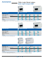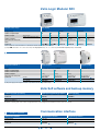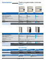
1
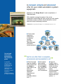
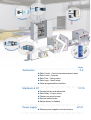
Control and connection
components
The essential guide
A compact, simple and advanced
offer for your small automation system
equipment.
Welcome to the Simply Smart* world, compliments of
Telemecanique.
With complete synergy throughout, the various
components constituting this offer provide you with simple
automation system solutions that are based on control
and input/output interfacing functions.
*Simply Smart: more ingenuity and intelligence for continually improving ease of use.
Control and
connection
components,
a complete
synergy
with other
Telemecanique
automation
system products.
Control and
connection
components
The essential
guide
A simplified
selection guide
enabling you to
quickly select all
the products
required to build
your small
automation system
equipment
(simple installations
& compact machines)
“
Opt for an offer that is complete,
economical and accessible to all
Save time and
improve reliability
with products that
are simple to
select and to use
(tailored
ergonomics,
simplified
mounting and
cabling,
assembly without
tools…).
Save space
with products
that are always
more compact,
thus simplifying
integration in
your installations.
”
Improve
flexibility with a
modular offer for
easily resolving
your changing
needs
(interchangeable
functions and
options, common
accessories and
options…).
○
○
○
○
○
○
○
○
○
○
○
○
○
○
○
○
○
○
○
○
○
○
○
○
○
○
○
○
○
○
○
○
○
○
○
○
○
○
○
○
○
○
○
○
○
Pages
○
Automation
○
○
○
○
2-9
Zelio Control - Control and measurement relays
Zelio Count - Counters
Zelio Time - Timing relays
Zelio Logic - Smart relays
Twido programmable controllers
○
○
○
○
○
○
○
○
○
○
○
○
○
○
○
○
○
○
○
○
○
○
○
○
○
○
○
○
○
○
○
○
○
○
○
○
○
○
○
○
○
○
○
○
○
Interfaces & I/O
○
○
○
○
○
10-19
Terminal blocks and cable ends
Zelio Relay - Plug-in relays
Telefast pre-wired system
Passive splitter boxes
Splitter boxes for fieldbus
○
○
○
○
○
○
○
○
○
○
○
○
○
○
○
○
○
○
○
○
○
○
○
○
○
○
○
○
○
○
○
○
○
○
○
○
○
○
○
○
○
○
○
○
Power supply
○
○
○
○
○
○
20-21
Phaseo power supplies and transformers
○
○
○
○
○
○
○
○
○
○
○
○
○
○
○
○
○
○
○
○
○
○
○
○
○
○
○
○
○
○
○
○
○
○
○
○
○
○
○
○
○
○
○
○
○
○
○
○
○
○
Automation
Zelio Control Relays
Control relays for 3-phase supplies
Function
Rotational direction and presence of phases
+ Undervoltage + Over and undervoltage
Adjustable time delay
without
without
0.1…10 s
0.1…10 s
fixed, 0.5 s
0.1…10 s
Supply voltage
200…500 V
380…500 V
400 V
380…500 V
380…500 V
380…500 V
Output
2 C/O
2 C/O
2 C/O
2 C/O
1 C/O
2 C/O
References
RM4TG20
RM4TU02
RM4TR34 (1)
RM4TR32 (2)
RM4TA02
RM4TA32
+ Asymmetry
(1) Relay with fixed voltage thresholds.
(2) Relay with adjustable voltage thresholds.
Current and voltage measurement relays
(3) Basic reference. To be completed with the letters
indicating the required voltage, as shown below:
Voltage
24…240 V
V AC, 50/60 Hz
V DC
MW
MW
110…130 V
F
–
220…240 V
M
–
380…415 V
Q
–
Function
Detection of
over and undercurrent
over and undercurrent
Measuring range
3…30 mA
0.3…1.5 A
0.05 …0.5 V
1…10 V
30…300 V
10…100 mA
1…5 A
0.3 …3 V
5…50 V
50…500 V
10…100 V
180…270 V
0.1…1 A
3…15 A
0.5…5 V
Adjustable time delay
0.05…30 s
0.05…30 s
0.05 …30 s
0.05…30 s
0.05…30 s
0.1…10 s
Output
2 C/O
2 C/O
2 C/O
2 C/O
2 C/O
2 C/O
References
RM4JA31•• (3) RM4JA32•• (3) RM4UA31•• (3) RM4UA32•• (3) RM4UA33•• (3) RM4UB35
Liquid level control relays
(4) Basic reference. To be completed with the letters
indicating the required voltage, as shown below:
RM4-LG01
Voltage
RM4-LA32
V AC, 50/60 Hz V AC, 50/60 Hz
V DC
24 V
B
B
–
24…240 V
–
MW
MW
110…130 V
F
F
–
220…240 V
M
M
–
380…415 V
Q
Q
–
Control relays
Empty or fill
Sensitivity scale
5 ... 100 kΩ
0.25 ... 5 kΩ
2.5 ... 50 kΩ
25 ... 500 kΩ
Time delay
without
adjustable, 0.1 to 10 s
Output
1 C/O
2 C/O
References
RM4LG01• (4)
RM4LA32•• (4)
Liquid level control probe type
Measuring electrode and
reference electrode
1 simple stainless steel electrode
in PVC protective casing
Mounting
suspended
suspended
Maximum operating temperature
100°C
100°C
References
LA9RM201
RM79696043
Other versions: please refer to your Schneider Electric agency.
2
Zelio Count - Counters
Totalisers
Display
Mechanical
LCD
Supply voltage
24 V DC
Number of digits displayed
5
6
6
8
8
Counting frequency
20 Hz
10 Hz
25 Hz
25 Hz
7.5 kHz
Battery
Type of zero reset
Manual
Without
Manual
Without
Manual (1)
Front face dimensions, W x H
41.5 x 31 mm
30 x 20 mm
60 x 50 mm
60 x 50 mm
48 x 24 mm
References
XBKT50000U10M
XBKT60000U00M
XBKT60000U10M
XBKT80000U00M
XBKT81030U33E
(1) With electrical interlocking.
Hour counters
Display
Mechanical
LCD
Supply voltage
24 V AC
230 V AC
Number of digits / display
7 (99,999.99 h)
7 (99,999.99 h)
8 (999,999.99 h)
Supply frequency
50 Hz
50 Hz
Mode: 1/100 hour
Type of zero reset
Without
Without
Manual (1)
Front face dimensions, W x H
48 x 48 mm
48 x 48 mm
48 x 24 mm
References
XBKH70000004M
XBKH70000002M
XBKH81000033E
Battery
(1) With electrical interlocking.
Multifunction counters
Display
LCD
Number of digits displayed
6
Counting frequency
5 kHz
Type of reset
Manual, electric and automatic
Front face dimensions, W x H
48 x 48 mm
Preselection number
References
Supply voltage
LED
1
2
1
24 V DC
XBKP61130G30E
XBKP61230G30E
XBKP62130G30E
2
XBKP62230G30E
115 V AC
XBKP61130G31E
XBKP61230G31E
–
–
230 V AC
XBKP61130G32E
XBKP61230G32E
XBKP62130G32E
XBKP62230G32E
Other versions: please refer to your Schneider Electric agency.
3
Automation
Zelio Time - Timing relays
Industrial timers
Type of single function relay
width 22.5 mm, relay output
On-delay
Off-delay
External control
no
yes
no
yes
yes
Supply voltage
24 V AC/DC
24 V AC/DC
24...240 V AC/DC
24 V AC/DC
24 V AC/DC
110…240 V AC
42…48 V AC/DC
42…48 V AC/DC
42…48 V AC/DC
110…240 V AC
110…240 V AC
110…240 V AC
Timing range
0.05 s...300 h
0.05 s...300 h
0.05 s...10 mn
0.05 s...300 h
0.05 s…300 h
Output
1 C/O
2 C/O (1)
1 C/O
2 C/O (1)
1 C/O
References
RE7TL11BU
RE7TP13BU
RE7RB11MW
RE7RL13BU
RE7RM11BU
(1) 1 selectable in instantaneous mode.
Type of single function relay
width 22.5 mm, relay output
Asymmetrical flashing
Pulse on energisation
External control
yes
no
Supply voltage
24 V AC/DC
24 V AC/DC
42…48 V AC/DC
110…240 V AC
110…240 V AC
Timing range
0.05 s...300 h
Output
1 C/O
0.05 s...300 h
1 C/O
References
RE7CV11BU
RE7PE11BU
Type of multifunction relay
6 functions (2)
8 functions (3)
Supply voltage
24 V AC/DC
24 V AC/DC
42…48 V AC/DC
110…240 V AC
110…240 V AC
Timing range
0.05 s…300 h
0.05 s…300 h
Output
1 C/O
2 C/O (1 selectable in instantaneous mode)
References
RE7ML11BU
RE7MY13BU
(2) RE7ML11BU functions: On-delay, Off-delay, Pulse on energisation with start on energisation, Pulse on energisation with start on opening of remote control contact, Flashing with
start during the OFF period, Flashing with start during the ON period.
(3) REMY13BU functions: On-delay, Off-delay, Pulse on energisation with start on energisation, Pulse on energisation with start on opening of remote control contact, Flashing with
start during the OFF period, Flashing with start during the ON period, Star-delta starting with double On-delay timing, Star-delta starting with contact for switching to star connection.
Other versions: please refer to your Schneider Electric agency.
4
Modular timers
Type of modular timer
width 17.5 mm, relay output
On-delay
Multifunction (1)
External control
no
–
Supply voltage
24 V DC - 24 ...240 V AC
24 V DC - 24 ...240 V AC
12 ... 240V AC/DC
Timing range
0.1 s…100 h
0.1 s…100 h
0.1 s…100 h
Output
1 C/O
1 C/O
1 C/O
References
RE88826115
RE88826105
RE88826103
–
(1) Multifunction: On-delay, Off-delay, Totaliser, Symmetrical flashing, Chronometer, Pulse on energisation.
Type of modular timer
width 17.5 mm, relay output
Asymmetrical
flashing
Pulse on
energisation
Off delay
Chronometer
External control
–
–
–
–
Supply voltage
24 V DC - 24…240 V AC 24 V DC - 24…240 V AC 24 V DC - 24…240 V AC 24 V DC - 24…240 V AC
Timing range
0.1 s…100 h
0.1 s…100 h
0.1 s…100 h
Output
1 C/O
1 C/O
1 C/O
1 C/O
References
RE88826155
RE88826145
RE88826135
RE88826125
Type of modular timer
width 17.5 mm, solid-state output
On-delay
0.1 s…100 h
Multifunction (1)
Supply voltage
24…240 V AC/DC
24…240 V AC
Timing range
0.1 s…100 h
0.1 s…100 h
Output
solid-state
solid-state
References
RE88826014
RE88826004
(1) Multifunction: On-delay, Off-delay, Totaliser, Symmetrical flashing, Chronometer, Pulse on energisation.
Other versions: please refer to your Schneider Electric agency.
5
Automation
Zelio Logic Smart relays
Zelio Logic Compact SR2
Compact smart relays
With display, d.c. power supply
Supply voltage
12 V DC
Number of inputs/outputs
12
20
10
12
20
20
discrete inputs
8
12
6
8
12
12
of which 0-10 V analogue inputs
Number of inputs
24 V DC
4
6
–
4
2
6
Number of outputs
4 relay
8 relay
4 relay
4
8 relay
8
Dimensions, W x D x H (mm)
71.2x59.5x107.6
124.6x59.5x107.6 71.2x59.5x107.6
Clock
yes
yes
no
yes
no
yes
References
SR2B121JD
SR2B201JD
SR2A101BD (1)
SR2B12p
pBD (2)
SR2A201BD (1)
SR2B20p
pBD (2)
124.6x59.5x107.6
(1) Programming on smart relay in LADDER language only
(2) Replace p by the number «1» to order a smart relay with relay outputs and by «2» for a smart relay with transistor outputs (Example: SR2B121BD)
Compact smart relays
With display, a.c. power supply
Supply voltage
24 V AC
Number of inputs/outputs
12
20
10
100/240 VAC
12
20
20
Number of discrete inputs
8
12
6
8
12
12
Number of outputs
4 relay
8 relay
4 relay
4 relay
8 relay
8 relay
Dimensions, W x D x H (mm)
71.2x59.5x107.6
124.6x59.5x107.6 71.2x59.5x107.6
Clock
yes
yes
no
References
SR2B121B
SR2B201B
SR2A101FU (1) SR2B121FU
124.6x59.5x107.6
no
no
no
SR2A201FU (1) SR2B201FU
(1) Programming on smart relay in LADDER language only
Compact smart relays
Without display and without buttons
Supply voltage
24 V DC
Number of inputs/outputs
10
12
20
10
12
20
6
8
12
6
8
12
Number of inputs
discrete inputs
of which 0-10 V analogue inputs
100/240 V AC
-
4
6
–
–
–
Number of outputs
4 relay
4 relay
8 relay
4 relay
4 relay
8 relay
Dimensions, W x D x H (mm)
71.2x59.5x107.6
Clock
no
yes
yes
yes
yes
References
SR2D101BD (1) SR2E121BD (3) SR2E201BD (3) SR2D101FU (1) SR2E121FU
124.6x59.5x107.6 71.2x59.5x107.6
no
124.6x59.5x107.6
SR2E201FU
(1) Programming on smart relay in LADDER language only
(3) For version with 24 VAC supply (0 analogue inputs), delete the letter D from the end of the reference (SR2E121B and SR2E201B)
Other versions: please refer to your Schneider Electric agency.
6
Zelio Logic Modular SR3
Modular smart relays*
With display
Supply voltage
24 V DC
Number of inputs/outputs
10
26
10
26
10
26
discrete inputs
6
16
6
16
6
16
of which 0-10 V analogue inputs
–
Number of inputs
24 V AC
100/240 VAC
4
6
–
–
–
Number of outputs
4
10
4 relay
10 relay
4 relay
Dimensions, W x D x H (mm)
71.2x59.5x107.6
124.6x59.5x107.6 71.2x59.5x107.6
Clock
yes
yes
References
pBD (1) SR3B101B
SR3B10p
pBD (1) SR3B26p
yes
10 relay
124.6x59.5x107.6 71.2x59.5x107.6
124.6x59.5x107.6
yes
yes
yes
SR3B261B
SR3B101FU
SR3B261FU
* Each modular base can be fitted with one communication module and one I/O expansion module.
(1) Replace p by the number «1» to order a smart relay with relay outputs and by «2» for a smart relay with transistor outputs (Example: SR3B101BD)
Available 2st quarter 2004
Expansion modules (2)
Inputs / Outpus
Communication
Usage
For modular smart relays SR3Bppppp
Number of inputs/outputs
6
10
14
Number of discrete inputs
4
6
8
–
Number of outputs
2 relay
4 relay
6 relay
–
Dimensions, W x D x H (mm)
References
MODBUS network
–
35.5x59.5x107.6
72x59.5x107.6
72x59.5x107.6
35.5x59.5x107.6
24 V DC
SR3XT61BD
SR3XT101BD
SR3XT141BD
SR3MBU01BD
24 VAC
SR3XT61B
SR3XT101B
SR3XT141B
–
100…240 VAC
SR3XT61FU
SR3XT101FU
SR3XT141FU
–
(2) The power supply of the expansion modules is provided via the Zelio Logic modular relays
Zelio Soft software and back-up memory
Software and back-up memory
Multilingual programmming software
Back-up memory
Description
PC CD-ROM (Windows 95/98, NT, 2000, XP, ME) (3)
EEPROM
References
SR2SFT01
SR2MEM01
PC/Smart relay connecting cable
SR2CBL01
–
Interface for USB port
SR2CBL06
–
(3) CD-Rom containing «Zelio Soft» software, an application library, a self-training manual, installation instructions and a user’s manual.
Available 2nd quarter 2004
Communication interface
Interface and software
Communication interface
Programming software
Supply voltage
12/24 V DC
–
Description
–
PC CD ROM (Windows 95/98, NT, 2000, XP, ME)
Dimensions, W x D x H (mm)
72x59.5x107.6
–
References
SR2COM01
SR2SFT03
Other versions: please refer to your Schneider Electric agency.
7
Automation
Twido programmable controller
Bases
Type of base
Compact
Supply voltage
100…240 V AC
Number of discrete inputs/outputs
10
16
24
Number of discrete inputs (24 V DC)
6 sink/source
9 sink/source
14 sink/source
Number of discrete outputs
4 relay, 2 A
7 relay, 2 A
10 relay, 2 A
Type of connection
Screw terminal block, non removable
Number of I/O expansion modules possible
–
Counting
3 x 5 kHz, 1 x 20 kHz
Serial ports
1 x RS 485
Protocols
Modbus Master/Slave, ASCII, remote I/Os
–
4
1 x RS 485; optional: 1 x RS 232C or RS485
Dimensions, W x D x H
80 x 70 x 90 mm
80 x 70 x 90 mm
95 x 70 x 90 mm
References
TWDLCAA10DRF
TWDLCAA16DRF
TWDLCAA24DRF
24 sink/source
Clock (optional)
TWDXCPRTC
Display (optional)
TWDXCPODC
Type of base
Modular
Number of discrete inputs/outputs
20
Number of discrete inputs (24 V DC) (1)
12 sink/source
12 sink/source
Number of discrete outputs
8 transistor, source 0.3 A
6 relay and 2 transistor, source 0.3 A 16 transistor, source 0.3 A
Type of connection
HE 10 connector
Removable screw terminal block
HE 10 connector
Number of I/O expansion modules possible
4
7
7
Supply voltage
24 V DC
Integrated counting and positioning
Counting: 2 x 5 kHz, 2 x 20 kHz; Positioning: PLS / PWM 2 x 7 kHz
Serial ports
1 x RS 485; optional: 1 x RS 232C or RS485
Protocols
Modbus Master/Slave, ASCII, remote I/Os
40
Dimensions, W x D x H
35.4 x 70 x 90 mm
47.5 x 70 x 90 mm
47.5 x 70 x 90 mm
References
TWDLMDA20DTK (1)
TWDLMDA20DRT
TWDLMDA40DTK (1)
Clock (optional)
TWDXCPRTC
Display (optional)
TWDXCPODM
Memory expansion (optional)
–
TWDXCPMFK64
(1) Also available: SINK transistor output versions (TWDLMDA20DUK and TWDLMDA40DUK) .
Accessories
Pre-wired system for modules with
HE 10 connector
For Modular Bases
TWDLMDA20DTK/40DTK
For Inputs
TWDDI16DK/32DK
For Outputs
TWDDO16TK/32TK
TwidoFast “bared” cable
L=3m
TWDFCW30M
TWDFCW30K
TWDFCW30K
L=5m
TWDFCW50M
TWDFCW50K
TWDFCW50K
L=1m
TWDFST20DR10
TWDFST16D10
TWDFST16DR10
L=2m
TWDFST20DR20
TWDFST16D20
TWDFST16DR20
Telefast connection bases
Memory Cartridge and Software
Memory cartridge
TwidoSoft software
Description
Application update
with cable
References
TWDXCPMFK32
TWDSPU1001V10M
Other versions: please refer to your Schneider Electric agency.
8
Input/output modules
Type of module
Analogue
Number of inputs/outputs
2 inputs
AS-Interface
master
1 output
2 inputs / 1 output
2 modules max.,
62 discrete modules max.,
7 analogue modules max.
Protocol/profile
–
AS-Interface/M3, V 2.11
Connection
Removable screw terminal block
(profile S-7.4 not supported)
Inputs
Range
0…10 V (1)
–
4…20 mA (2)
outputs
Resolution
12 bits (4096 points)
–
Range
–
0…10 V
0…10 V (1)
Thermocouple type K, J, T –
4…20 mA (2)
Pt 100 3-wire temperature probe
12 bits (4096 points)
–
–
4…20 mA
Resolution
–
Measuring precison
0.2 % PE
Supply voltage
24 V DC
Dimensions, WxDxH
23,5 x 70 x 90
References
TWDAMI2HT
12 bits (4096 points)
–
23,5 x 70 x 90
TWDAMO1HT
TWDAMM3HT
4 Inputs / 4 Outputs
16
TWDALM3LT
TWDNOI10M3
16
32
(1) (non differential)
(2) (differential)
Type of module
Discrete
Number of Discrete inputs/outputs
8
Connection
Removable screw terminal block
References
HE 10 connectors
Inputs 24 V DC (1)
TWDDDI8DT
TWDDMM8DRT
TWDDDI16DT
TWDDDI16DK
TWDDDI32DK
Relay outputs 2 A
TWDDRA8RT
TWDDMM8DRT
TWDDRA16RT
–
–
Transistor outputs, source 0.1 A
TWDDDO8TT (2)
–
–
TWDDDO16TK (2)
TWDDDO32TK (2)
(1) All inputs are sink/source.
(2) Also available: SINK transistor output versions (TWDDDO8UT, TWDDDO16UK and TWDDDO32UK).
Communication modules
Type of module
Serial interface module
Serial interface adaptor
Communication type (non isolated)
RS 232C
Connection
Mini-DIN connector
Protocol
Modbus Master/Slave, ASCII, remote I/Os
Twido base compatibility
Modular base TWD LMDA
References
TWDNOZ232D
RS 485
RS 232C
RS 485
Screw terminals Mini-DIN connector
Screw terminals
Compact base TWD LCAA 16/24 DRF
Modular base via built-in display module TWDXCPODM
TWDNOZ485D
TWDNOZ485T
TWDNAC232D
TWDNAC485D
TWDNAC485T
Other versions: please refer to your Schneider Electric agency.
9
Interfaces & I/O
Terminal blocks
Insulation displacement technology
Clip-on mounting on 35 mm
1 mm2 c.s.a.
2.5 mm2 c.s.a.
rails
2-way terminal blocks
(sold in lots of 100)
End covers
(sold in lots of 10)
2-pole commoning link (1)
(sold in lots of 10)
AB1RRAL22
Conducting
AB1AA135U2GR
AB1AAAC122GR
Protective earth conductor
AB1AATP135U2
AB1AAAC122VE
-
Conducting
AB1AA235U2GR
AB1AAAC122GR
AB1RRAL22
Protective earth conductor
AB1AATP235U2
AB1AAAC122VE
-
(1) For a 3, 4, 5 or 10-pole commoning link replace the last number of the reference (2) by 3, 4, 5 or 10 respectively. (Example: AB1RAL22 becomes AB1RAL23).
Spring clamp technology
Clip-on mounting on 35 mm
2.5 mm2 c.s.a.
4 mm2 c.s.a.
6 mm2 c.s.a.
10 mm2 c.s.a.
16 mm2 c.s.a.
rails
Terminal blocks
(sold in lots of 100)
End covers
(sold in lots of 10)
2-pole commoning link (1)
(sold in lots of 10)
AB1RRAL22 (1)
Conducting
AB1RR235U2GR
AB1RRAC242GR
Protective earth conductor
AB1RRTP235U2
AB1RRTPAC242
–
Conducting
AB1RR435U2GR
AB1RRAC242GR
AB1RRAL42 (1)
Protective earth conductor
AB1RRTP435U2
AB1RRTPAC242
–
Conducting
AB1RR635U2GR
–
AB1RRAL62
Protective earth conductor
AB1RRTP635U2
–
–
Conducting
AB1RR1035U2GR (2)
–
AB1RRAL102
Protective earth conductor
AB1RRTP1035U2 (2)
–
–
Conducting
AB1RR1635U2GR (2)
–
AB1RRAL162
Protective earth conductor
AB1RRTP1635U2 (2)
–
–
(1) For a 3, 4, 5 or 10-pole commoning link replace the last number of the reference (2) by 3, 4, 5 or 10 respectively. (Example: AB1RRAL22 becomes AB1RRAL23).
(2) Sold in lots of 50.
Screw clamp technology
Clip-on mounting on 35 mm
2.5 mm2 c.s.a.
4 mm2 c.s.a.
6 mm2 c.s.a.
10 mm2 c.s.a.
16 mm2 c.s.a.
rails
Terminal blocks
(sold in lots of 100)
End covers
(sold in lots of 50)
2-pole commoning link (1)
(sold in lots of 10)
AB1ALN22 (1)
Conducting
AB1VV235U
AB1AC24
Protective earth conductor
–
–
–
Conducting
AB1VV435U
AB1AC24
AB1ALN42 (1)
Protective earth conductor
AB1TP435U
–
–
Conducting
AB1VV635U
AB1AC6
AB1ALN62 (1)
Protective earth conductor
AB1TP635U
–
–
Conducting
AB1VVN1035U (2)
AB1ACN10
AB1ALN102 (1)
Protective earth conductor
AB1TP1035U (2)
–
–
Conducting
AB1VVN1635U (2)
AB1ACN16
AB1ALN162 (1)
Protective earth conductor
AB1TP1635U (2)
–
–
(1) For a 3, 4, 5 or 10-pole commoning link replace the last number of the reference (2) by 3, 4, 5 or 10 respectively. (Example: AB1ALN22 becomes AB1ALN23).
(2) Sold in lots of 50.
Other versions: please refer to your Schneider Electric agency.
10
Insulated cable ends
Conforming to DIN 46228 (1)
mm2
Øb
Øb1 c
0.5
3
1.4
0.75
3.1
1.6
13
1
3.4
1.8
13.5
1.5
4
2.1
13.5
2.5
4.6
2.7
14.5
13
Type
Single cable ends
Sold in lots of 10 x 100
Packaging
Individual or “strings” of bags
Dispenser pack
Strips of 50 in bag
Conductor c.s.a.
0.5
White
DZ5CE005D
AZ5CE005D
DZ5CEB005D
in mm2
0.75
Grey
DZ5CE007D
AZ5CE007D
DZ5CEB007D
1
Red
DZ5CE010D
AZ5CE010D
DZ5CEB010D
1.5
Black
DZ5CE015D
AZ5CE015D
DZ5CEB015D
2.5
Blue
DZ5CE025D
AZ5CE025D
DZ5CEB025D
mm2
Øb
Øb1 c
c1
0.75
2.8 x 5
1.8
8
1
3.4 x 5.4 2.05 15
8
1.5
3.6 x 6.6 2.3
15
8
2.5
4.2 x 7.8 2.9
18.5 10
15
Type
Double cable ends
Sold in lots of 5 x 100
Packaging
Dispenser pack
Conductor c.s.a.
2 x 0.75
Grey
AZ5DE007D
in mm2
2x1
Red
AZ5DE010D
2 x 1.5
Black
AZ5DE015D
2 x 2.5
Blue
AZ5DE025D
(1) For insulated cable ends conforming to standard NF C 63-023 , please refer to your Schneider Electric agency.
Cabling accessories
Type
Pliers/cutters
Functions
Stripping
Cutting/stripping Crimping
Crimping (ratchet) Cutting/stripping/crimping (2)
For cable c.s.a.
0.08 to 4 mm2
0.4 to 4 mm2
0.5 to 16 mm2
0.25 to 6 mm2
0.5 to 2.5 mm2
References
AT1PA7
AT2PE1
AT1PA2
AT2PA5
AT2TRIF01
(2) For use with cable ends packed in strips of 50.
Other versions: please refer to your Schneider Electric agency.
11
Interfaces & I/O
Zelio Relay - Plug-in relays
Interface relays
Type of relay
Interface relays RSB
Contact characteristics
Thermal current Ith in A (temperature ≤ 40°C)
8
12
16
Number of contacts
2 C/O
1 C/O
1 C/O
Contact material
AgNi
AgNi
AgNi
Switching voltage, min. / max.
5 / 250 V AC/DC
5 / 250 V AC/DC
5 / 250 V AC/DC
Breaking capacity, min. / max.
5 mA / 2000 VA
5 mA / 3000 VA
5 mA / 4000 VA
Coil characteristics
Average consumption, inrush, VA / W
0.75 VA / 0.45 W
Permissible voltage variation
0.8 ….1.1 Un (50 / 60Hz or =)
References
Coil supply voltage
on DC
(1)
(1)
(1)
6 V DC
RSB2A080RD
RSB1A120RD
RSB1A160RD
12 V DC
RSB2A080JD
RSB1A120JD
RSB1A160JD
24 V DC
RSB2A080BD
RSB1A120BD
RSB1A160BD
48 V DC
RSB2A080ED
RSB1A120ED
RSB1A160ED
60 V DC
RSB2A080ND
RSB1A120ND
RSB1A160ND
RSB1A160FD
110 V DC
RSB2A080FD
RSB1A120FD
Coil supply voltage
24 V AC
RSB2A080B7
RSB1A120B7
RSB1A160B7
on AC
48 V AC
RSB2A080E7
RSB1A120E7
RSB1A160E7
110 V AC
–
–
–
120 V AC
RSB2A080F7
RSB1A120F7
RSB1A160F7
220 V AC
RSB2A080M7
RSB1A120M7
RSB1A160M7
230 V AC
RSB2A080P7
RSB1A120P7
RSB1A160P7
240 V AC
RSB2A080U7
RSB1A120U7
RSB1A160U7
(1) References for relays without socket. For relays with socket, add the letter S to the end of the selected reference. (Example: RSB2A080B7 becomes RSB2A080B7S).
Sockets for relays
Type of socket
For interface relays RSB
Mixed input/output type sockets
without location for protection module
–
–
–
with location for protection module
–
–
–
RSZE1S48M
RSZE1S38M
RSZE1S48M
Separate input/output type sockets
with location for protection module
Protection modules
Diode, 6…230 V DC
RZM040W
Diode + LED, 6…24 V DC
RZM031RB
Diode + LED, 24…60 V DC
RZM031BN
Diode + LED, 110…230 V DC
RZM031FPD
Varistor + LED, 6…24 V DC or AC
RZM021RB
Varistor + LED, 24…60 V DC or AC
RZM021BN
Varistor + LED, 110…230 V DC or AC
RZM021FP
RC circuit, 24…60 V AC
RZM041BN7
RC circuit, 110…240 V AC
RZM041FU7
“Power on” indication, 110/230 V AC
–
“Power on” indication, 6/24 V DC with protection diode
–
Varistor, 24 V AC
–
Varistor, 230 V AC
–
Multifunction timer module, 24…230 V DC or AC
–
Accessories
Plastic extractor
RSZR215
Maintaining spring clamp
–
Legend for sockets
RSZL300
Other versions: please refer to your Schneider Electric agency.
12
Miniature and universal relays
Miniature relays RXL
Universal relays RUN with contact position mechanical
indicator
12
10
6
6
10
10
4
2 C/O
3 C/O
4 C/O
4 C/O
2 C/O
3 C/O
3 C/O
AgNi
AgNi
AgNi
AgNi/AU 5 u
AgNi
AgNi
AgNi/AU 10 u
5 / 250 V AC/DC
5 / 250 V AC/DC
5 / 250 V AC/DC
5 / 250 V AC/DC
20 / 250 V AC/DC
20 / 250 V AC/DC
10 / 250 V AC, 125 V DC
5 mA / 3000 VA
5 mA / 2500 VA
5 mA / 1500 VA
2 mA / 1500 VA
50 mA / 3000 VA
50 mA / 3000 VA
1 mA / 1000 VA
1.6 VA / 0.9 W
2.3 VA / 1.5 W
0.8 ….1.1 Un (50 / 60Hz or =)
0.8 ….1.1 Un (50Hz or =), 0.85…1.1Un (60Hz)
(2)
(2)
(2)
(2)
(2)
(2)
–
–
–
–
–
–
–
–
RXL2A12B1JD
RXL3A10B1JD
RXL4A06B1JD
RXL4G06B1JD
RUN21D21JD
RUN31A21JD
–
RXL2A12B1BD
RXL3A10B1BD
RXL4A06B1BD
RXL4G06B1BD
RUN21D21BD
RUN31A21BD
RUN33A22BD
RXL2A12B1ED
RXL3A10B1ED
RXL4A06B1ED
RXL4G06B1ED
RUN21D21ED
RUN31A21ED
RUN33A22ED
–
–
–
–
–
–
–
RXL2A12B1FD
RXL3A10B1FD
RXL4A06B1FD
RXL4G06B1FD
RUN21D21FD
RUN31A21FD
–
RXL2A12B1B7
RXL3A10B1B7
RXL4A06B1B7
RXL4G06B1B7
RUN21D21B7
RUN31A21B7
RUN33A22B7
RUN33A22E7
RXL2A12B1E7
RXL3A10B1E7
RXL4A06B1E7
RXL4G06B1E7
RUN21D21E7
RUN31A21E7
–
–
–
–
RUN21D21F7
RUN31A21F7
RUN33A22E7
RXL2A12B1F7
RXL3A102B1F7
RXL4A062B1F7
RXL4G062B1F7
–
–
–
–
–
–
–
–
–
–
RXL2A12B1P7
RXL3A10B1P7
RXL4A06B1P7
RXL4G06B1P7
RUN21D21P7
RUN31A21P7
RUN33A22P7
–
–
–
–
–
–
–
(2) References for relays without status LED indicator. For relays with status LED indicator, replace the last number 1 in the reference by 2. (Example: RXL2A12B1JD becomes
RXL2A12B2JD).
For miniature relays RXL
For universal relays RUN with contact position mech. indicator
RXZE1M114 (3)
–
RXZE1M114
RXZE1M114
RUZ1D
RUZ1A
RUZ1A
RXZE1M114M
–
RXZE1M114M
RXZE1M114M
RUZ7D
RUZ7A
RUZ7A
RXZE1S108M
RXZE1S111M
RXZE1S114M
RXZE1S114M
–
RZM040W
RUW040BD
RZM031RB
–
RZM031BN
–
RZM031FPD
–
RZM021RB
–
RZM021BN
–
RZM021FP
–
RZM041BN7
–
RZM041FU7
RUW041P7
–
RUW010P7
–
RUW030BD
–
RUW042B7
–
RUW042P7
–
RUW101MW
RXZR235
–
RXZ200
RUZ200
RXZL320
–
(3) Limited to 7 A in operation.
Other versions: please refer to your Schneider Electric agency.
13
Interfaces & I/O
Telefast 2 pre-wired system
Passive I/O sub-bases «Discrete»
Type of connection sub-base
Optimum
Number of channels
16
16
Max. current per channel
0.5 A
0.5 A
Control voltage / output voltage
24 V DC / 24 V DC
24 V DC / 24 V DC
LED per channel
–
With
Number of terminals per channel/on row number
1/2
1/1
Dimensions, W x D x H
55 x 59 x 67 mm
106 x 60 x 49 mm
References
2/2
3/3
–
ABE7H16C11
ABE7H16C21
ABE7H16C31
Cable L = 1 m
ABE7H20E100 (1)
–
–
–
Cable L = 2 m
ABE7H20E200 (1)
–
–
–
Cable L = 3 m
ABE7H20E300 (1)
–
–
–
Connection cable recommended for Modicon, TSX Micro and Premium PLCs, L = 1 m (2)
ABFH20H100
(1) Connection cable supplied for PLCs.
(2) For a 2 m length cable, replace the number 1 in the reference by 2, and for a 3 m length, by 3. (Example: ABFH20H100 becomes ABFH20H200).
Type of connection sub-base
Universal
Number of channels
16
Max. current per channel
0.5 A
Control voltage / output voltage
24 V DC / 24 V DC
LED per channel
–
With
–
–
With
With
Number of terminals per channel/on row number
1/1
1/1
1/2
2/2
2/2
3/3
Dimensions, W x D x H
125 x 58 x 70 mm
84 x 58 x 70 mm 125 x 58 x 70 mm
References
ABE7H16R10
ABE7H16R50
ABE7H16R21
ABE7H16R31
ABE7H16R11
ABE7H16R20
Connection cable recommended for Modicon, TSX Micro and Premium PLCs, L = 1 m: ABFH20H100 (2)
(2) For a 2 m length cable, replace the number 1 in the reference by 2, and for a 3 m length, by 3. (Example: ABFH20H100 becomes ABFH20H200).
Type of connection sub-base
For counter and
analogue channels
Passive distribution
with shielding continuity
Distribution and supply
of analogue channels
Number of channels
1 counter channel (3)
8
8
Max. current per channel
25 mA
25 mA
25 mA
Control voltage / output voltage
24 V DC / 24 V DC
Number of terminals per channel
2
2 or 4
2 or 4
Dimensions, W x D x H
143 x 58 x 70 mm
125 x 58 x 70 mm
125 x 58 x 70 mm
References
ABE7CPA01
ABE7CPA02
ABE7CPA03
–
–
Connection cable recommended
for Modicon PLCs (4)
TSX Micro
L = 2.5 m
TSXCCPS15
Premium
L=3m
TSXCAP030
(3) Or 8 inputs + 2 outputs, analogue .
(4) Connection cables available for other PLCs, please refer to your Schneider Electric agency.
Other versions: please refer to your Schneider Electric agency.
14
Sockets with plug-in relays and terminals
Type of connection sub-base
With soldered solid-state
relay inputs
With soldered solid-state
relay outputs
With soldered electromechanical relay outputs
Number of channels
Max. current per channel
16
16
16
12 mA
0.5 A
Input voltage / output voltage
24 V DC / -
2A
- / 24 V DC
- / 5…30 V DC, 230 V AC
Number of contacts
Polarity distribution
–
–
1 N/O
–
–
Number of terminals per channel
2
(1)
Dimensions, W x D x H
206 x 58 x 77 mm
References
ABE7S16E2B1 ABE7S16E2F0
110 V AC / -
5A
Volt-free
ABE7S16S2B0(2) ABE7S16S1B2 ABE7R16S111
ABE7R16S210
Connection cable recommended for Modicon, TSX Micro and Premium PLCs, L = 1 m: ABFH20H100 (3)
(1) Contact common per group of 8 channels.
(2) With fault detection signal (can only be used with modules with protected outputs).
(3) For a 2 m length cable, replace the number 1 in the reference by 2, and for a 3 m length, by 3. (Example: ABFH20H100 becomes ABFH20H200).
Type of connection sub-base
With plug-in electromechanical relays
Number of channels
16
Max. current per channel
5A
Control voltage / output voltage
24 V DC / 5…24 V DC, 230 V AC
Number of contacts
1 N/O
Polarity distribution
(4)
Number of terminals per channel
2
2 or 3
2 to 6
Dimensions, W x D x H
110x54x89 mm
211 x 64 x 89 mm
272 x 74 x 89 mm
References
ABE7R16T111
ABE7R16T212
2.5 A
4A
5A
1 C/O
(5)
2 C/O
Volt-free
ABE7R16T210
ABE7R16T230
ABE7R16T330
ABE7R16T370
Connection cable recommended for Modicon, TSX Micro and Premium PLCs, L = 1 m: ABFH20H100 (6)
(4) Contact common per group of 4 channels.
(5) Common on both poles.
(6) For a 2 m length cable, replace the number 1 in the reference by 2, and for a 3 m length, by 3. (Example: ABFH20H100 becomes ABFH20H200).
Connection cables for PLCs (7)
Input/Output functions
References
Discrete
Analogue
Analogue
and counter
Counter
Axis control
Cable L = 1 m
ABFH20H100
–
–
–
–
Cable L = 2 m
ABFH20H200
ABFY25S200
–
–
TSXCXP213
Cable L = 2.5 m
–
–
TSXCCPS15
TSXCCPH15
–
Cable L = 3 m
ABFH20H300
TSXCAP030
–
–
–
Cable L = 6 m
–
–
–
–
TSXCXP613
(7) Modicon, TSX Micro and Premium PLCs.
For other connection cables and accessories, please refer to your Schneider Electric agency.
Other versions: please refer to your Schneider Electric agency.
15
Interfaces & I/O
Passive splitter boxes
IP67, Telefast ABE9
Type of connection
To PLC using multicore cable
Number of channels
4
8
Type of female connector
M12, 5-pin
M12, 5-pin
Max. number of signals
8
16
Max. current per channel
4A
Max. current per splitter box
16 A (1 mm2)
Product certification
cULus
Dimensions, W x D x H
References
Without LEDs
With LEDs (1)
50.2 x 42 x 92.2 mm
50.2 x 42 x 149.2 mm
Cable L = 5 m
ABE9C1240L05
ABE9C1280L05
Cable L = 10 m
ABE9C1240L10
ABE9C1280L10
Cable L = 5 m
ABE9C1241L05
ABE9C1281L05
Cable L = 10 m
ABE9C1241L10
ABE9C1281L10
(1) Green LED: power supply status, yellow LED: channel status.
Type of connection
To PLC using M23 connector
Number of channels
4
8
Type of female connector
M12, 5-pin
M12, 5-pin
Max. number of signals
8
16
Max. current per channel
4A
Max. current per splitter box
16 A
Product certification
cULus
Dimensions, W X D x H
References
50.2 x 36.5 x 92.2 mm
50.2 x 36.5 x 149.2 mm
Without LEDs
ABE9C1240C23
ABE9C1280C23
With LEDs (1)
ABE9C1241C23
ABE9C1281C23
(1) Green LED: power supply status, yellow LED: channel status.
Accessories
Type of accessory
References
Splitter boxes w/o cable
Terminal connectors
Without LEDs With LEDs
Cable L = 5 m
Sealing plugs
4-channel
ABE9C1240M
ABE9C1241M
ABE9XCA1405 ABE9XCA1410 –
8-channel
ABE9C1280M
ABE9C1281M
ABE9XCA1805 ABE9XCA1810 –
for Ø12 connector
–
–
–
Cable L = 10 m (sold in lots of 10)
–
FTXCM12B
Other versions: please refer to your Schneider Electric agency.
16
Cabling accessories
M12 / M12 jumper cables
Type
Male / Female jumper cables
Type of male connector, interface side
M12, 3-pin, straight, screw thread
M12, 4-pin, straight, screw thread M12, 5-pin, straight, screw thread
Type of female connector, sensor side
M12, 3-pin, straight, screw thread
M12, 4-pin, straight, screw thread M12, 5-pin, straight, screw thread
Cable
References
Cable
PUR, black
PUR, black
PUR, black
L=1m
XZCR1511040A1
XZCR1511041C1
XZCR1511064D1
L=2m
XZCR1511040A2
XZCR1511041C2
XZCR1511064D2
M12 / M8 or DIN jumper cables
Type
Male / Female jumper cables
Type of male connector, interface side
M8, 3-pin
M12, 3-pin
M12, 3-pin
M12, 3-pin
straight, screw thread
straight, screw thread
straight, screw thread
straight, screw thread
M8, 3-pin
M8, 3-pin
M8, 3-pin
DIN 43650A
straight, screw thread
straight, clip together
straight, screw thread
elbowed, screw thread
PUR, black
PUR, black
PUR, black
PUR, black
L=1m
XZCR2705037R1
XZCR1501040G1
XZCR1509040H1
XZCR1523062K1
L=2m
XZCR2705037R2
XZCR1501040G2
XZCR1509040H2
XZCR1523062K2
Type of female connector, sensor side
Cable
References
Cable
Connectors, splitter box
Type
Connectors
Type of male connector, interface side
M12, 4-pin
M8, 3-pin
M12, 5-pin, straight, screw thread 1 x M12
1 x M12
Type of female connector, sensor side
–
–
–
2 x M8
–
–
PUR, black
Cable
References
Pre-wired connectors
Splitter box “Y”
2 x M12
–
Straight connector, screw thread
XZCC12MDM40B XZCC8MDM30V –
FTXCY1212
Elbowed connector, screw thread
XZCC12MCM40B –
–
–
FTXCY1208
–
Cable
L = 0.5 m
–
–
XZCP1564L05
–
–
L=2m
–
–
XZCP1564L2
–
–
Other versions: please refer to your Schneider Electric agency.
17
Interfaces & I/O
Splitter boxes for fieldbus
Plastic enclosure, IP67, Advantys FTB
Available 4th Q. 2003
Type of bus
CANopen
Number of channels
8
Type of female connector
M12, 5-pin
Max. voltage / current of inputs
24 V DC / 200 mA
Max. voltage / current of outputs
24 V DC / 1.6 A
Max. current per splitter box
8A
Product certification
cULus
Dimensions, W X D x H
Diagnostics
References
DeviceNet
ProfiBus
63 x 50.5 x 220 mm
InterBus
63 x 69 x 220 mm
Splitter boxes
By LED for: bus and I/O undervoltage + I/O short-circuit + I/O power supply
Channels
By LED for: I/O short-circuit + wire breakage fault + I/O fault
16 inputs
FTB1CN16EP0
FTB1DN16EP0
FTB1DP16EP0
FTB1IB16EP0
8 inputs/8 outputs
FTB1CN08E08SP0
FTB1DN08E08SP0
FTB1DP08E08SP0
FTB1IB08E08SP0
12 inputs/4 outputs
FTB1CN12E04SP0
FTB1DN12E04SP0
FTB1DP12E04SP0
FTB1IB12E04SP0
16 configurable inputs/outputs
FTB1CN16CP0
FTB1DN16CP0
FTB1DP16CP0
FTB1IB16CP0
Metal enclosure, IP67, Advantys FTB
Available 4th Q. 2003
Type of bus
DeviceNet
Number of channels
8
Type of female connector
M12, 5-pin
Max. voltage / current of inputs
24 V DC / 200 mA
Max. voltage / current of outputs
24 V DC / 1.6 A
Max. current per splitter box
8A
Product certification
cULus
Dimensions, W x D x H
Diagnostics
References
ProfiBus
62.7 x 38.9 x 224.7 mm
Splitter boxes
By LED for: bus and I/O undervoltage + I/O short-circuit + I/O power supply
Channels
By LED for: I/O short-circuit + wire breakage fault + I/O fault
16 inputs
FTB1DN16EM0
FTB1DP16EM0
8 inputs/8 outputs/configurable outputs FTB1DN08E08CM0
FTB1DP08E08CM0
16 configurable inputs/outputs
FTB1DP16CM0
FTB1DN16CM0
Other versions: please refer to your Schneider Electric agency.
18
Accessories for FTB splitter boxes
Bus connection cables
(1) For sensor and actuator cabling accessories:
see page 17
Type of bus
CANopen
Type of female connector
M12, 5-pin, at either end
Connector coding
A encoded
B encoded
–
L = 0.3 m
FTXCN3203
FTXDP3203
–
L = 0.6 m
FTXCN3206
FTXDP3206
FTXIB1206 (2)
L=1m
FTXCN3210
FTXDP3210
FTXIB1210 (2)
L=2m
FTXCN3220
FTXDP3220
FTXIB1220 (2)
L=3m
FTXCN3230
FTXDP3230
–
L=5m
FTXCN3250
FTXDP3250
FTXIB1250 (2)
References
Cable
DeviceNet
ProfiBus
InterBus
–
(2) Reference includes the Bus connection cable + the power supply cable.
Power supply connection cables
Type of bus
CANopen
Type of female connector
References
ProfiBus
Type 7/8, 5-pin, at either end
Cable
L = 0.6 m
FTXDP2206
L=1m
FTXDP2210
L=2m
FTXDP2220
L=5m
FTXDP2250
Type of female connector
References
DeviceNet
Type 7/8, 5-pin, at one end (other end free)
Cable
L = 1.5 m
FTXDP2115
L=3m
FTXDP2130
L=5m
FTXDP2150
Accessories
Type of bus
References
CANopen
Configuration CD-ROM
FTXES00
Diagnostics M12 adaptor
FTXDG12
Power supply T-connector
FTXCNCT1
Line terminator
FTXCNTL12
DeviceNet
ProfiBus
Interbus
–
FTXDPTL12
–
Other versions: please refer to your Schneider Electric agency.
19
(1)
Power supply
Phaseo power supplies and transformers
Power supplies for control circuits
Type of power supply
Compact, 1-phase regulated switch mode (1) Modular, 1-phase regulated switch mode
AUTO reset of automatic protection
AUTO reset of automatic protection
Input voltage
100…240 V AC, 110…220 V DC (compatible)
100…240 V AC
Output voltage
24 V DC
24 V DC
12 V DC
24 V DC
Nominal Power / Current
15 W / 0.6 A
30 W / 1.2 A
22 W / 1.9 A
30 W / 1.3 A
Certifications
cULus, TÜV
UL, CSA, TÜV
Safety
UL508, IEC/EN 60950
IEC/EN 60950, IEC/EN 61131-2/A11
EMC
EN 50081-2, EN 50082-2
EN 50081-2, IEC 61000-6-2 (EN 50082-2)
Conducted and radiated
EN 55011, EN 55022 cIass A EN 55011, EN 55022 cIass B
Conformity to standards
Emission
Dimensions, W x D x H
45 x 95 x 75 mm
References
ABL7CEM24006
72 x 70 x 110 mm
ABL7CEM24012
ABL7RM1202
ABL7RM2401
(1) Wide range.
Type of power supply
Universal, 1-phase regulated switch mode, wide range
AUTO reset of automatic protection
Input voltage
100…240 V AC, 110…230 V DC (version ABL7RP••)
Output voltage
24 V DC
Nominal Power / Current
48 W / 2 A
Certifications
UL, CSA, TÜV, Ctick
Conformity to standards
Emission
72 W / 3 A
120 W / 5 A
Safety
IEC/EN 60950
EMC
EN 50081-2, IEC 61000-6-2 (EN 50082-2)
Low frequency harmonic currents
–
Conducted and radiated
EN 55011, EN 55022 cIass B
240 W / 10 A
EN 61000-3-2
Dimensions, W x D x H
27 x 120 x 120 mm
54 x 120 x 120 mm
References
ABL7RE2402
ABL7RE2405
ABL7RE2403
–
EN 61000-3-2
135 x 120 x 120 mm
ABL7RP2405(1) ABL7RE2410
ABL7RP2410(1)
(1) AUTO/MAN reset of automatic protection.
Type of power supply
Industrial, 2-phase regulated switch mode
AUTO/MAN reset of automatic protection
Input voltage
2 x 380…415 V AC
Output voltage
24 V DC
24 V DC
Nominal Power / Current
120 W / 5 A
240 W / 10 A
Conformity to standards
Emission
Safety
IEC/EN 60950
EMC
EN 50081-1, EN 50082-2
Low frequency harmonic currents
–
Conducted and radiated
EN 55011, EN 55022 cIass B
2 x 380…415 V AC
Dimensions, W x D x H
68 x 130 x 127 mm
68 x 154 x 127 mm
References
ABL7REQ24050
ABL7REQ24100
Other versions: please refer to your Schneider Electric agency.
20
Power supplies for control circuits
Type of power supply
Industrial, 3-phase regulated switch mode, wide range
AUTO/MAN reset of automatic protection
Input voltage
3 x 400…520 V AC
Output voltage
24 V DC
Nominal Power / Current
120 W / 5 A
Certifications
cULus, c
Conformity to standards
Emission
240 W / 10 A
480 W / 20 A
960 W / 40 A
84 x 240 x 209 mm
106 x 275 x 242 mm
ABL7UPS24200
ABL7UPS24400
us
Safety
IEC/EN 60950
EMC
EN 50081-1, EN 50082-2
Low frequency harmonic currents
–
Conducted and radiated
EN 55011, EN 55022 cIass B
EN61000-3-2
Dimensions, W x D x H
68 x 171 x 127 mm
References
ABL7UES24050
Type of power supply
Rectified and filtered
Input voltage
215/230/245 or 385/400/415 V AC (±10%) 1-phase
Output voltage
24 V DC
ABL7UPS24100
380/400/420 V AC (±10%) 3-phase
Certifications
c
Nominal power
24 W
60 W
120 W
240 W
360 W
480 W
240 W
480 W
720 W
960 W
Nominal current
1A
2.5 A
5A
10 A
15 A
20 A
10 A
20 A
30 A
40 A
Power supply references
us
1-phase
ABL6RF24•• (1)
01
02
05
10
15
20
–
–
–
–
3-phase
ABL6RT24•• (1)
–
–
–
–
–
–
10
20
30
40
(1) Complete the reference according to the power and current using the adjacent table (example: ABL6RF2401).
Transformers
Type of transformer
Safety and isolation
Primary voltage
230/400 V AC (±15%) 1-phase
Secondary
Single or double winding (see references below)
Certifications
Nominal power
References, single winding
25 VA
40 VA
63 VA
100 VA
160 VA
250 VA
400 VA
630 VA
1000 VA
12 V
02J
04J
06J
10J
16J
25J
–
–
–
24 V
02B
04B
06B
10B
16B
25B
40B
63B
100B
115 V
02G
04G
06G
10G
16G
25G
40G
63G
100G
230 V
02U
04U
06U
10U
16U
25U
40U
63U
100U
ABL6TS••• (1)
Output voltage
References, double winding
ABL6TD••• (1)
Output voltage
24/48 V
02B
04B
06B
10B
16B
25B
40B
63B
100B
115/230 V
02G
04G
06G
10G
16G
25G
40G
63G
100G
(1) Complete the reference according to the power and voltage using the table below (example: ABL6TS02J).
Other versions: please refer to your Schneider Electric agency.
21
The commitment
of Schneider Electric services
“
A unique
partner,
a global
presence.
”
Constantly available worldwide
With more than 5,000 points of sale in 130
countries, you can be sure to find the range
of products which is right for you and which
complies fully with the standards in the
country in which they are to be used.
Technical assistance wherever you are
Schneider Electric Industries S.A.S.
Head office
89, bd Franklin Roosevelt
92500 Rueil-Malmaison Cedex
France
ART. 060315
http://www.schneider-electric.com
Owing to changes in standards and equipment, the characteristics given in the text and images in this document
are not binding until they have been confirmed with us.
Production: IGS-CP
Photos: Schneider Electric - Thierry Laroche - Photo BT
Printed by: SOPAN
02/2004 - V2
DIA3ED2030704EN
Schneider provides you with all necessary
technical assistance throughout the world.
In addition, our technicians are at your
disposal to assist you in finding the
optimum solution for your particular needs.