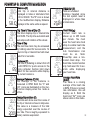
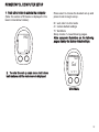
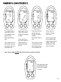
1
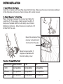
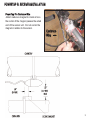
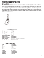
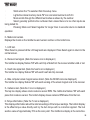
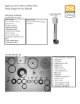
OWNER’S MANUAL
PowerTap SL
Copyright
Copyright 2003. All rights reserved. No part of this publication may be copied, photographed,
reproduced, translated, transmitted electronically or placed on digital media without the prior
written consent of Saris Cycling Group, Inc.
Trademarks
Saris Cycling Group, Inc , PowerTap and the PowerTap logo, are all registered trademarks of Saris
Cycling Group, Inc. All other product, brand, or trade names used in this manual may be trademarks
or registered trademarks of their respective owners.
Modifications
Saris Cycling Group, Inc reserves the right to make improvements and/or updates to the products
described herein at any time without notice.
Saris Cycling Group, Inc.
5253 Verona Road
Madison, WI USA
www.cycleops.com
1-800-783-7257
16034 A 12/04
Patents Issued and Pending
Patent #6,418,797
2
CONTENTS
Introduction
System Overview
Wheel Building
System Installation
PowerTap SL Receiver Installation
PowerTap SL General Operation
PowerTap SL Computer Navigation
PowerTap SL Interval Mode
PowerTap SL Computer Set Up
Maintenance & Specifications
Hub Batteries/O-ring Replacement
Test Mode
Trouble Shooting
Warranty and Technical Support
4
5
6
7
9
11
12
14
15
23
27
28
30
38
3
INTRODUCTION & PRECAUTIONS
Thank you for your purchase of the CycleOps PowerTapTM . Power is the ultimate measure of
performance. No other equipment will give you greater return on your investment. For more
information regarding training with power, please go to our Web site at www.cycleops.com
PRECAUTIONS: IMPORTANT
1. Before beginning any training program, always check with your physician.
2. Keep your eyes on the road. Do not become overly engaged with the PowerTap display. We recommend familiarizing yourself with computer functions while stationary.
3.The computer,receiver,and hub are water resistant.However,avoid extended submersion or high-pressure sprays directed at PowerTap components.
4.Wash off dirt with a mild detergent on a soft cloth.Wipe excess water off with a dry cloth.Do not apply
kerosene, paint thinner, alcohol, benzine or other such solvents to any PowerTap components.
5.The plastic cover on the hub should be removed only when replacing batteries, or when allowing the
unit to dry after submersion in water. Repeated disassembly may compromise the effectiveness of the
O-ring seals. O-rings should be inspected and replaced if necessary whenever the battery cover is
removed. Use a light coating of grease when reinstalling the battery cap on the O-rings.
6.The PowerTap wheel does not include a quick release skewer. CycleOps recommends using a
steel skewer.
7. Both sides of the PowerTap should be built using a 3x spoke lacing pattern. Because of the design of
the PowerTap, torque is transmitted through the hub to the non-drive side.
8. Electromagnetic interference, such as interference caused by high power lines, may briefly disrupt the
communication between the hub, chest strap and computer.
9. The PowerTap is available only in a 130 & 135mm range of axle lengths to accommodate different
frames and uses. Only use similarly sized frames and hubs. Failure to adhere to these precautions may
cause premature failure or incorrect operation of the unit and may void the warranty.
10. Please register your PowerTap at www.cycleops.com.
4
SYSTEM OVERVIEW
The PowerTap System
The PowerTap system includes a power-measuring hub which measures torque and wheel
speed. This information is then transmitted via digital radio frequency to a receiver mounted on
the seat stay. The data is wired to the PowerTap computer mounted on the handlebar. The computer receives the signal from the heart rate monitor chest strap to provide heart rate information.
All of this information is then processed for display on the computer.
Preparing for Installation
The PowerTap hub comes either in a pre-built wheel or alone, ready to build into a wheel. The
power measuring hub must be built into a complete wheel prior to installation. Other items necessary for installation are a cassette, spoke protector, reflectors, skewer, rim strip, tire, and tube
(clincher rim) or glue and tubular tire (tubular rim). Please read all instructions prior to installation.
Also take a moment to verify the package contents. The installation procedure with a complete
wheel requires only a trimmer to clip the cable ties. However, assembling the wheel, cassette and
other parts requires the proper tools and experience. If you are unsure of any step of the procedure or do not have all of the tools necessary for installation, contact your local dealer
for assistance.
Package Contents
Qty
1
1
1
1
4
12
1
1
1
1
1
10
1
Item
PowerTap hub (or built wheel)
PowerTap computer
Receiver
Chest strap
Foam mounting tapes
Cable ties
Training With Power guide by CTS
Product registration card
PowerLink Lite CD
Link cable
Cadence Magnet (Pro Model Only)
Cadence Sensor Cable Ties
Extra CPU Battery
5
SYSTEM OVERVIEW
Compatibility
The PowerTap SL hub is compatible with Shimano 8, 9, and 10 speed systems or
Campagnolo 8, 9, and 10 speed. Free hub bodies may be interchanged. See page 24 for
instructions.
Only
insert
the
correctly
spaced
PowerTap
hub
into
your
frame.
For example, only use a 130mm-spaced hub in a 130mm road frame. Do not force the hub
into any frame. Doing so may cause failure of the frame, hub, or both, and will void the
warranty. Contact your dealer or PowerTap to address any special compatibility issues.
WHEEL BUILDING
Contact your local wheel building professional or dealer for assistance in building the PowerTap
hub if not provided as a complete wheel. The flanges are drilled for 14 or 15 gauge spokes. Use
at least a two-cross pattern on both sides of the hub. Due to the design of the hub, the load path
is not the same as with a conventional hub. Slotting the hub flanges to accommodate bladed
spokes is not recommended and will void the warranty.
Reference a spoke-length calculator when building a wheel.
Wheel Building Dimensions
Measurements
Drive
Non-Drive
Hub center to flange
17.4mm
31.7mm
Flange Diameter
70mm
70mm
Spoke hole diameter: 2.5mm
6
SYSTEM INSTALLATION
1. Insert Wheel Into Frame
Insert the complete built PowerTap wheel into the frame. Make sure the axle is correctly positioned
in the dropouts and secure wheel in place with a steel skewer.
2. Attach Receiver To Seat Stay
Place foam tape between the receiver and frame for
a slip-free fit. If necessary, rotate receiver to within 5
degrees of parallel with the hub battery cover before
tightening cable ties. Mount receiver a maximum of 3
inches from the axle.
Mount the bottom of the
receiver a maximum of
3 inches from the axle
Mount receiver within 5
degrees of parallel with
the hub battery cover.
Receiver Compatibility Chart
Receiver Standard
Pro
SL
7 inch
Compatible
Compatible
Compatible
3-5 inch
Compatible
Compatible
Incompatible
Max 3 inch
Compatible
Compatible
Compatible
7
SYSTEM INSTALLATION
Figure 3: Mounting of computer shoe
Figure 4: Attaching of computer
Figure 5: Placement of heart rate strap
3. Attach Computer Mount to Handlebar
The computer mounts to the handlebar in a similar fashion. Position the foam mounting tape
beneath the mount and secure with cable ties to handlebar. The head of the cable tie fits flush
into a recessed cavity on the mount.
4. Place Computer
Place the computer into the mounting shoe on the handlebar. Line up the slots on the base of the
computer with the bracket. Slide completely into computer mount. (see figure 4)
5. Heart Rate Monitor Strap
Position the heart rate monitor strap on your torso as pictured in figure 6.
The strap should rest just beneath the pectoral muscles of the chest. Make
sure the electrodes on the strap are slightly moist where it contacts the
skin for best results. The heart rate strap must be worn to enable the heart
rate functionality of the PowerTap. (see figure 5) The chest strap is not
coded.
6. Verify Installation
Check all the components to make sure they are securely attached.
Spin the rear wheel and verify that the transmission icon on the computer
display is illuminated. This indicates that the hub is sending a valid signal
through the receiver to the cpu. (see figure 6). Adjust the receiver
if necessary.
Figure 6: Transmission icon in
upper left corner of display
8
POWERTAP SL RECEIVER INSTALLATION
PowerTap Pro Cadence Wire
-Attach cadence magnet to crank arm so
the center of the magnet passes the wired
end of the sensor unit. Do not center the
magnet in relation to the sensor.
Cadence
Wire
9
Yellow 1 CPU
Black CPU
Yellow 2 CPU
PowerTap Models
PowerTap Recording Rates
1sec.
Black
Yellow 1
Yellow 2
2 sec.
5 sec.
10 sec.
30 sec.
3.5
7
NA
NA
NA
7.5
15
30
60
180
15
30
60
120
360
43,690 data points available
10
POWERTAP SL GENERAL OPERATION
General Operation of Computer
The PowerTap SL has three main displays: power
display (top), speed display (middle), and multifunction display (bottom). There are two main
modes of operation in the PowerTap: trip mode and
interval mode.
Mode Button
Press the mode button to scroll between the
different displays. The active display is indicated by
small black triangles at the left and right side of the
display. Hold the mode button down for two seconds to toggle between trip and interval modes. The
"INT" icon will illuminate when you enter interval
mode as well as the current interval number.
Select Button
Press the select button to select which function is
shown on the current display. The current function
will remain on the display even when the mode button is used to move to another display.
Menu (Both Buttons)
Hold both buttons for 2 seconds to enter the scrolling menu. There are two options to select by releasing the buttons: clr to clear all data and the main
menu to enter setup. See page XX for set up information.
Power Conservation
The computer and hub have power saving features
to prolong battery life. The computer powers down
the display after 4 minutes of inactivity. Press one of
the buttons to activate the display. Similarly, the hub
powers down after two minutes of inactivity. The
transmission icon will not be visible when the hub is
asleep. Spin the wheel momentarily and the icon will
illuminate.
TRANS.
ICON
POWER
DISPLAY
SPEED
DISPLAY
INTERVAL
DISPLAY
MULTI
DISPLAY
MODE (LEFT)
Changes active
mode
BOTH
Clear data
Enter setup
SELECT (RIGHT)
Select function
Figure 7: PowerTap button and display summary
11
POWERTAP SL COMPUTER NAVIGATION
Current Power
Instantaneous power output is
displayed from 0 to 1999 watts in
1 watt increments. The "WATTS"
label is visible during this mode on
the power display.
Maximum Power
This value is the highest recorded power output since the last
time this data was cleared. Both
the "WATTS" label and the "MX"
icon denote maximum power.
Average Power
This function displays the calculated average power output
measured over the course of your
ride. The "WATTS" label and the
"AV" icon are visible when average
power is shown.
365
3
25
WATTS
MI
D
MX
58.I0
849
3
25
WATTS
MI
D
58.I0
I95
3
25
AV WATTS
MI
D
Torque
The torque function
the
torque
3 shows
placed on the hub in
MI
inch-pounds. To display
torque, hold down the
D
select button for two
seconds while on the watts display in
trip mode. The"WATTS" label is not visible with torque. Press select to return
to the power display.
000
25
58.I0
58.I0
Current Speed
Your current speed is displayed
in miles per hour or kilometers
per hour up to 99.9 mi/hr or
km/hr in 0.1 mi/hr or km/hr increments. Only "MI" or "KM" is
shown with current speed.
Maximum Speed
This function displays the highest recorded value of the speed.
The maximum speed is shown
with " MI " or "KM" and the "MX"
icon on the speed display.
Average Speed
This function displays average
speed in miles or kilometers
per hour. Average speed displays with "MI" or "KM" and the
“AV" icon on the speed display.
365
3
25
WATTS
MI
D
58.I0
365
33 7
WATTS
MI
MX
D
58.I0
365
20 3
WATTS
AV
D
MI
58.I0
IMPORTANT How To Zero Torque
Occasionally, the torque must be zeroed to ensure
that the PowerTap displays the most accurate
power information. If the instantaneous power is
positive or negative while coasting, the torque
needs to be zeroed. This operation must be done
while coasting with no tension in the chain or while
stationary with no force being placed on the pedals. Also, the transmission icon must be illuminated.
To zero torque, hold down the select (right) button for two
seconds to enter torque mode. Then hold down select
again until “0” is shown. Push select once to return to
watts. The torque value will now read zero.
12
POWERTAP SL COMPUTER NAVIGATION
Distance (D)
Total trip or interval distance is
365
365
3 displayed in miles or kilometers from
3
to 999.99. The "D" icon is shown
25 0.00
25
on the multifunction display. Distance
WATTS
WATTS
MI
D
58.I0
MI
displays in the same units as speed.
2584
Odometer (O)
Total accumulated
distance travelled since
the last system reset is
displayed in whole miles
or kilometers.
O
Trip Time & Time of Day (T)
The timer displays trip or interval time
WATTS
3 to 9.59.59. The trip time auto starts and
auto stops with rotation of the wheel.
MI
Time of Day
The real time clock may be accessed
by holding select for two seconds. To
return to trip or interval time hold down
select for 2 seconds.
365
25
365
3
25
2.5 I.43
I72
T
WATTS
MI
365
3 Cadence (C)
rate of pedaling is shown from 20
25 The
to 240 RPM. For quick access to the
365
3
25
computer function hold down
89 cycle
select for two seconds while display-
152
WATTS
MI
C
ing current cadence.
WATTS
MI
C
mode is
AV
Energy Expenditure (E)
The total work done over the course of
WATTS
the trip or interval is shown in kilojoules.
3 This value is a measure of the total
MI
energy expended over the course of
your ride. This is roughly equivalent to
E
dietary calories expanded.
365
25
2009
MI
AV
Average Cadence (C AV)
365 The
average of the cadence is
3
in RPM. Both the "C" and
25 measured
“AV" icons are illuminated on the muldisplay when this
76 tifunction
active.
WATTS
Heart Rate( )
Current heart rate is
shown up to 255 beats
per minute. You must
wear the heart rate chest
strap to enable heart rate
measurement, and the
hub transmission icon
must be on. Note:
PowerTap uses a noncoded chest strap. For
heart rate monitor function
only hold select for 2 seconds while displaying
your heart rate.
Average Heart Rate
( AV)
This value is a running
average of the heart rate
in BPM. If there is no heart
rate information, this will
display as 0. Both the
heart and "AV" 'icons are
shown while in this mode.
13
POWERTAP SL INTERVAL MODE
SL Interval Mode
The PowerTap Pro Interval mode functions differently than the previous
PowerTap computers. It works as a lap marker, and is essentially always on.
To begin the first interval, or advance the interval, simply press both buttons
down simultaneously from any location or mode in the display. “INT” and
the new interval # will briefly appear, before disappearing again to the background. To view interval specific information (duration, distance, averages,
etc) simply hold down the mode button for two seconds. This brings interval mode to the foreground. “INT” and the interval number will constitute a
fourth line in the display (see picture at right). When you wish to relegate the
interval information to the background again, simply depress the mode button for two seconds.
watts
int
speed
multi
SL Interval Memory Mode
To access stored interval information select “INT” by pushing mode until
“INT” blinks. Then hold select for 2 seconds until M appears next to the
interval number indicating you are now viewing interval information. Push
select to advance to the interval you wish to view and push mode to select
the information you wish to view. (Ave. watts, cadence, etc.)To exit Interval
Memory Mode hold mode for 2 seconds. Note that recovery periods as well
as work periods are displayed in memory mode.
SL Interval Shortcut
To quickly mark intervals simply push both buttons simultaneously from
either trip or interval mode. If in trip mode “INT” will briefly appear indicating
you have marked an interval and which number interval you are on.
14
POWERTAP SL COMPUTER SETUP
1. Push either button to activate the computer.
(Note: the version of firmware is displayed in the
lower corner-shown below)
PRO
Press select to choose the desired set up and
press mode to begin set up.
E = exit, return to ride mode
d = restore default settings
T= Test Mode
Setup modes 1-4 see following pages.
Note: computer illustrations on the following
pages display the factory default settings.
2.2
Set
t
Ed
2. To enter the set up main menu hold down
both buttons until the main menu is displayed
1234
Main Menu
15
POWERTAP SL COMPUTER SETUP
PowerTap SL
The PowerTap SL has three levels to the display:
Power
d
Speed
Multi
300
watts
300
watts
300
watts
25
25
25
mi
mi
mi
5
5
5
d
d
Press the Mode button to change levels (the active level is indicated
by the black arrows) and press the select button to change the
function displayed within the level. (Ave and max for watts and
speed, distance, time, cadence, ave. cadence, energy expenditure
in kilojoules, odometer, heart rate and ave. heart rate for the
multi display).
16
POWERTAP SL COMPUTER SETUP 1
Std
Std
12
p
p
12:00
t
t
t
Press select button to
select 12 or 24 hour
clock.
Press mode button to
save.
Std
Press select button to
select AM(A) or PM(P).
Press mode button to
save.
Press select button to
change digits.
Press mode button to
advance.
Year
Std
Std
03
r c
e
0 1 - 0 1
c
5
Day
Month
Press select button to
select year, month
and date.
Press mode button to
advance.
Press select button to
select the storage
rate.(1,2,5,10,or
30seconds.)
Press mode button to
save.
Run Time: Different storage rates yield
different amounts of total storage time.
Refer to the chart on left to select the most
appropriate storage rate.
17
POWERTAP SL COMPUTER SETUP 1
Std
Std
1
r
CI
Std
1
1
ODo
MI
2096
00000
Press select button to
select English or Metric
units.
Press mode button to
save.
Press select button to
change digits.
Press mode button to
advance to next digit.
Press select button to
select starting Odometer
reading.
Press mode button to
save.
Refer to wheel circumference guide for
correct tire circumference. A roll out measurement (mm) of the
rear wheel will give
greatest accuracy.
Note:Odometer settings
are saved during battery
changes.
Tire Size
Wheel Circumferences
Circ.(mm)
Tire Size
24 x1
26 x1
26 x1.25
26 x1.5
26 x 2.0
26 x 2.125
27 x1
27 x11/8
1753
1913
1953
1986
2055
2070
2125
2139
27 x1 1/4
700C tubular
700 x 20C
700 x 23C
700 x 25C
700 x 28C
700 x 32C
700 x 38C
Circ.(mm)
2152
2094
2084
2096
2108
2116
2136
2170
18
POWERTAP SL COMPUTER SETUP 2
PRO
PRO
PRO
PRO
AV WATTS
2
2
3
2
AV
5
2
2
rEg
MI
C
AV
AV
Press select button to
set rate of display for
watts. (rolling average)
Press mode button to
save.
Press select button to
set rate of display for
speed. (rolling average)
Press mode button to
save.
Press select button to set
rate of display for
cadence. (rolling average)
Press mode button to
save.
This function can be
useful for allowing for
better pacing during
Time Trial efforts by
allowing for a slower
update of the display.
This function can be
useful for allowing for
better pacing during
Time Trial efforts by
allowing for a slower
update of the display.
This function is useful for
customizing how smooth
the cadence display is for
cadence based workouts.
(1 sec. = display updates approx. every second, 3 = every 3 seconds etc.)
Note: These settings DO NOT affect the data that is stored for download.
Press select button to set
rate of display for heart rate.
(rolling average)
reg = regular averaging
slo = slow averaging
fst = fast averaging
Press mode button to save.
This function can be useful
for allowing for better pacing
during Time Trial efforts by
allowing for a slower update
of the display.
PRO
go
2
do it
Press select then mode
to reset defaults, press
mode to save changes
or “go do it”.
19
POWERTAP SL COMPUTER SETUP 3
3
PRO
PRO
PRO
AV WATTS
s
s
s
0’
0’
0’
3
Press select button to
select YES or NO for
zeros included in averaging of watts.
Press mode button to
save.
This is useful if you are
curious what your average power is when you
are pedaling only.
3
YES
YES
AV MI
YES
PRO
YES
c
Press mode to select
YES or NO for zeros
included in averaging
or speed.
Press select button to
select if zeros are
included in Cadence
average.
Press mode button to
save.
This is useful if you
are curious what your
average speed is
when you are pedaling only.
t
av
This is useful if you are
curious what your average cadence is when
you are pedaling only.
Torque auto-zero
function. Normally
leave at yes.
This is useful for track
bike use where large
negative torque may be
present. Note: Hub
modification to fixed
gear is necessary.
Note: These settings DO NOT affect the data that is stored for download.
PRO
go
2
do it
Press select then mode
to reset defaults, press
mode to save changes
or “go do it”.
20
POWERTAP SL COMPUTER SETUP 4
PRO
PRO
PRO
P
4
4
4
4
mi
SLEEP
Press select to set how
many minutes the CPU
will stay “awake” after not
receiving a valid speed or
heart rate signal.
The shorter the sleep time
the better the battery life.
Press select button to select what
is displayed in the middle line.
(mi= speed, c=cadence,
=heartrate). Also, whatever is
selected will flash during the ride
to indicate what is displayed in
the middle screen.
Note that if heart rate or cadence
is selected speed is not displayed
at all.
Hu
pedal
c
Press select button to
select the cadence
information source
Default = pedal then hub
Pedal = crank only
Hub = hub only
This function is useful for intervals
when power, heart rate and
cadence are of most concern.
21
POWERTAP SL COMPUTER SETUP 4
PRO
PRO
PRO
watts
4
4
4
mi
mi
Fig.8
Fig.10
Fig.9
The PowerTap Pro allows you to
use the unit as a cycle computer
or heart rate monitor only. Fig. 8
illustrates the Power Meter Mode .
Press mode to leave in this setting. Push select to change to
cycle computer mode.
Figure 9 illustrates cycle computer only mode. This mode
requires a wheel magnet on a
non-PowerTap rear wheel.
Align the magnet towards the
bottom edge of the receiver
so that it passes within 3mm
of the receiver.
PRO
PRO
watts
watts
4
4
Push select until display
looks like fig. 10 for heart
rate only function. When
this is in use all that will be
displayed is current heart
rate, average heart rate,
trip time and time of day.
PRO
watts
4
go
mi
data
Fig.11
Press select to choose autostart
control by speed (fig. 11). This will
allow trip time to count whenever
wheel speed is registering. If speed
is not registering trip time will stop
after 3 seconds.
data
do it
Fig.12
Press select to choose autostart
control by heart rate (fig.12). This will
allow trip time to count as long as
heart rate is registered. This function
is useful for transitioning from cycling
to running and vice versa.
Press mode button to
save (do it), press select
button then mode to
reset defaults.
22
MAINTENANCE & SPECIFICATIONS
The PowerTap SL uses a completely new free hub, axle and bearing design that should provide
many miles of trouble free training and racing. The following information will help you keep your
PowerTap SL running properly. If you are not familiar with hub maintenance please consult a professional bicycle mechanic before servicing.
During the course of any repair DO NOT remove the torque tube. There are no user serviceable
parts inside. Special tools are required for reassembly and calibration. If problems are suspected contact Saris Cycling Group.
Bearings
The power measuring components inside the PowerTap SL are highly complex and should only
by serviced by Saris Cycling Group. The bearings are sealed type 6901RS and do not require
replacement. Field replacement can cause permanent damage to the power measuring electronics and result in compromised sealing and performance. If bearing problems are suspected
please contact Saris Cycling Group for a return authorization. The PowerTap SL uses a modern
4 bearing design and does not require any tensioning adjustment.
23
MAINTENANCE & SPECIFICATIONS
Freehub
The grease in the freehub pawls should be replaced if it becomes contaminated with water.
Replace the seal at the same time, contact Saris Cycling Group for replacement parts. Saris
Cycling Group recommends the following types of grease to ensure proper functioning:
-Kluber Isoflex NB52 o
-Dupont Krytox GPL226
Warning: Failure to use the proper grease on the freehub pawls could result in engagement
problems.
Freehub replacement
-Use 5mm hex wrench and 17mm bike wrench and remove both end nuts from the axle.
-Remove the axle
-Remove the freehub and spacers.
-Remove all old grease from the freehub ratchet ring.
-Install spacers per the illustration.
-Install axle.
-Apply 2 grams of high quality freehub grease to the ratchet ring.
-Grease the V seal and place it on the freehub and install onto shaft.
-Replace end nuts. Torque end nuts to 12 lbs-ft.
24
25
MAINTENANCE & SPECIFICATIONS
Computer Batteries
The PowerTap SL has batteries in the hub and computer. Computer batteries typically need to be changed
every 1,000 km or approximately every 100 hours of use. The cpu will also say "low bat" when the cpu battery needs to be changed. This message is displayed after a "clr" is performed. To replace computer battery (Type CR2032), remove the computer from the mount. Remove the battery cover on the back of the computer (it works best to use a cone wrench to remove the battery cover), exchange the battery, and replace
the the cover as shown below.
Technical Specifications
Accuracy
Signal Transmission
Interval Data Storage
Interval Display
Operational Temperature
Battery Life (Hub)
Battery Life (Computer)
Battery Type: Hub
Battery Type: Computer
+/- 1.5%
Digital RF
unlimited
9Ointervals
O
0 to 40 C
300 hours approx.
100 hours approx.
357, 1.55Volts, ANSI/NEDA-1131SO,IEC-SR44
CR2032/ANSI 5004LC
Range of Measurement
Power
Torque
Speed
Distance
Trip Time
Cadence
Total Energy
Odometer
Heart Rate
0 - 1999 watts
0 - 1999 inch-lbs
2 - 59 mph
3 - 95 kph
0.00.00 - 999:59
40 - 140 RPM
0 - 99999 kJoules
0 - 99999 mi or km
0 - 255 BPM
26
HUB BATTERIES
Normal battery life in the hub is 250 to 300 hours of actual ride time. Use #357 Silver Oxide type
batteries and always replace batteries in pairs. Alkaline type batteries give shorter life and poorer performance.
Battery replacement
-Unscrew the plastic battery cover. Use a spanner wrench or bench vise opened wide to get it started if stuck.
There are O-ring seals that can cause the cover to resist the start of motion. The threading is normal right hand.
-Remove the inner O-ring for ease of installation.
-Remove the battery pack. A small screw driver can be used back and forth between the to ends to start to lift
it out.
-Pop the battery out by bending the plastic retaining tap back and pushing the batter up from the bottom.
-Check that the electrical connector tab from the inside of the hub is perpendicular to the bottom of the battery
pocket. If the tab gets bent, gently press it back to perpendicular with a non-sharp tool.
-Slide the battery pack back into position along the center core. As the battery is engaged a small increase of
resistance to installation should be felt as the electrical connections are made.
-Reinstall the O-ring.
-Grease the inside of the cap where the inner and outer O-rings
make contact. Use a high quality bicycle grease.
-Thread the cap all the way back on.
-Replacement O-rings and battery
packs are available from Saris
Cycling Group.
27
TEST MODE
·
Starts when the 't" is selected from the setup menu.
·
Lights the interval memory mode "M" icon and small number to left of it.
·
Mode scrolls through the different test modes as shown by the number.
·
Select generally performs the numbered item unless there is to be other inputs are
being tested for.
·
Pressing Mode and Select together for longer than 2 seconds returns to standard
operation
0 - Model and version.
Displays the model on the middle line and version number on the bottom line.
1 - LCD test.
When Select is pressed all the LCD segments are displayed. Press Select again to return to the
normal screen.
2 - Receiver test signal. (Note the receive icon is displayed.)
The middle line display flashes "88" with each blip of data from the receiver whether valid or not.
3 - Heart rate signal test. (Note the heart icon is displayed.)
The middle line display flashes "88" with each heart rate blip received.
4 - Bike computer wheel magnet sense detect. (Note the MI KM icons are displayed.)
The middle line display flashes "88" with each sensing of the wheel magnet next to the receiver.
5 - Cadence test. (Note the C icon is displayed.)
The top line display shows crank cadence sensor RPM. The middle line flashes "88" with each
pulse from cadence sensor. The bottom display shows cadence RPM value from the hub.
6- Torque information. (Note the T icon is displayed.)
This displays information about the internal workings of the torque readings. The bottom display
is the offset torque value directly sent by the hub torque with no correction applied. The hub
sends a value of approximately 512 as the zero point. The middle line display is the correction28
TEST MODE
offset value currently stored in the CPU. This is the value that is changed when you do a manual
zeroing of the torque. The top display is the corrected actual torque (the bottom value minus the
middle value).
7 - Standard test file.
This mode writes a small test file to the memory. Press the Select button and the bottom lines says
"run" and then "yes" when the file is written. This file can then be downloaded.
8 - Communication loop back test.
When looking at the front side of the CPU, use a coin or paper clip to short out the two pins on
the left side. Then press the Select button. The bottom line will say "run" and then "yes" if it passes the test correctly. If the pins are not shorted together or there was a problem, the display will
say "no". This test can be repeated by pressing the Select button.
9 - Fast Memory test.
This does a quick test of the memory in the CPU. Press Select and it displays "run" on the bottom
line. When the test is completed and it passes, it says "yes". If the test should fail, the bottom line
will say "no".
29
TROUBLESHOOTING
Recording Setting(Seconds)
Maximum Recording Time (Hrs)
1
7.5
2
15.0
5
30
10
60
30
180
No display on computer screen
·Computer is asleep - press one of the buttons on the computer to wake up the computer.
·Batteries need replacement - replace the computer batteries as shown on pages 14-15 of the User Manual.
·Computer too cold- operating temp. is 25 to 110 degrees Fahrenheit
Computer display is on, but there is no transmission icon
·Hub is asleep - spin the wheel momentarily to wake up the hub.
·Batteries need replacement - replace the hub batteries as shown on pages 14-15 of the User Manual.
·Computer not seated in mount - make sure computer is firmly and correctly mounted in handlebar mount.
·Communication errors - verify that the receiver is positioned as shown in the installation section. PowerTap
receivers with serial numbers less than 27383 the bottom of the receiver should be at
least 7 inches from the axle. For receivers with serial numbers greater than 27383 the bottom of the receiver
should be less than 3 inches from the axle. Inspect receiver & computer mount for
damaged wire or gold colored contacts.
·Moisture in hub - remove cover to see if there is any condensation on the battery cover. If there is, leave cover off
in a dry place for 12 hours or until moisture disappears.
·Interference with other devices - make sure you are not setting up the PowerTap inside a building with a lot of electrical noise, neon signs, or near power lines. Bring the PowerTap outside or away
from the electrical disturbance to see if signal returns. Also make sure you don't have any other devices on your
bike such as lights, magnets or cycle computer sensors.
·PowerTap computer's batteries are low, replace batteries as shown on pages 14-15 of the User Manual. We recommend using a Cone Wrench to remove the battery cap, not a coin.
·Check the PowerTap Receiver wire and computer mount for damage.
· Displayed data blinks or does not function
·Batteries need replacement - replace the computer batteries as shown on pages 14-15 of the User Manual.
·Computer not seated in mount - make sure computer is firmly and correctly mounted in handlebar mount.
·Interference with other devices - make sure you are not setting up the PowerTap inside a building with a lot of electrical noise, neon signs, or near power lines. Bring the PowerTap outside or away
from the electrical disturbance to see if signal returns. Also make sure you don't have any other devices on your
bike such as lights, magnets or cycle computer sensors.
·Check for damage to receiver & computer mount.
Power seems incorrect
· Torque value is not zeroed to manually read zero torque go to current watts and hold down the select button until
watts disappears. Torque is now being displayed. To zero torque hold down the
select button until the value reads zero. To exit torque mode press select once. If read zero the torque does not
seem to recalibrate the unit call PowerTap customer service at 1-800-783-7257
Speed seems incorrect
· Wheel size incorrect -refer to the chart on page 14 and enter the correct size in setup mode.
Transmission icon flashes rapidly
· Hub batteries need replacement - replace the hub batteries as shown on pages 14-15 of the User Manual.
30
TROUBLESHOOTING
Link Software
The following are some problems you might have when installing and setting up your Link Software. This list will be
evolving, so please visit our web site for a current troubleshooting guide: http://www.cycle-ops.com. If your problem
is not addressed here you can call Customer Service at 1-800-783-7257.
General Link Trouble Shooting
Raw Data Files
Some of the more sneaky of you will try calculating power/heart rate for just one ride to see how cardiac fatigue
might be affecting your ride. You'll do this by running the .CSV file in Excel and calculating the factor for each
record. Then you'll replace the calculated column for the existing, say, Torque column. This is very naughty. You
need to know that as soon as you import that data into your database, it will affect your entire database history until
you delete the ride. If you want to try such experiments, it's best to import such adulterated data into a separate
rider name.
Database Management
As long as you are keeping all the raw data (.CSV) files, you can always start over by importing the files again.
Remember that you can always delete a ride and rider from the database to start over.
Data Differences Between Link and PowerTap Computer
There are two issues here, data inconsistency and time differences. First the display on the PowerTap CPU has a 3
sample running average. This 3 sample average is used for displaying averages
and maximums on the PowerTap computer display. This reduces the "jumpiness" of the numbers and makes it easier to use while riding.
The data saved for download is raw, exactly as it is sent to the hub.
In the CPU set up mode (press MODE and SELECT buttons simultaneously until you see 'SETUP') you can select 1
or 2 sample recording. If you select 1 the data is sent to the CPU from the hub at 1-second intervals. The 1-second mode will save every data point sent from the hub. If you select 2 the data is sent to the CPU at 2-second
intervals. The 2-second mode will in effect save only every other data point sent from the hub. Therefore in the 2second mode Maximums can be missed.
So between the averaging and the save rate the data download will be different. In the 1-second mode the download data is always most accurate.
The second issue is time differences. The data points used for display on the CPU may not coincide perfectly with
what is stored to memory. There can be up to a 1-sample (or 1-second) loss at the start and stop of a download
file. If the CPU is in 2-second mode this max time error (2-seconds at the start and/or stop) can be as much as 4seconds off.
The individual raw data records written to memory are extremely accurate. In fact the data has been proven in laboratory testing to be accurate to +/- 1.5%. This means the data downloaded to the Link accurately represents what
was happening on your bike second by second. How we repackage the data, to make it useable does not affect or
detract from its accuracy - it's just making it more user friendly.
31
TROUBLESHOOTING
and maximums on the PowerTap computer display. This reduces the "jumpiness" of the numbers and makes it easier to use while riding.
The data saved for download is raw, exactly as it is sent to the hub.
In the CPU set up mode (press MODE and SELECT buttons simultaneously until you see 'SETUP') you can select 1
or 2 sample recording. If you select 1 the data is sent to the CPU from the hub at 1-second intervals. The 1-second
mode will save every data point sent from the hub. If you select 2 the data is sent to the CPU at 2-second intervals. The 2-second mode will in effect save only every other data point sent from the hub. Therefore in the 2-second mode Maximums can be missed.
So between the averaging and the save rate the data download will be different. In the 1-second mode the download data is always most accurate.
The second issue is time differences. The data points used for display on the CPU may not coincide perfectly with
what is stored to memory. There can be up to a 1-sample (or 1-second) loss at the start and stop of a download
file. If the CPU is in 2-second mode this max time error (2-seconds at the start and/or stop) can be as much as 4seconds off.
The individual raw data records written to memory are extremely accurate. In fact the data has been proven in laboratory testing to be accurate to +/- 1.5%. This means the data downloaded to the Link accurately represents what
was happening on your bike second by second. How we repackage the data, to make it useable does not affect or
detract from its accuracy - it's just making it more user friendly.
Some of the values on the ride chart don't make any sense - I don't remember going 170 miles per hour!
The scale on both the right side and the left side of the graph consolidates several measured values and therefore
must share the common vertical axis. So, to avoid 'tall' power curves and extremely 'short' speed curves, the speed
is shown as a multiple of 10.
Sometimes interference can cause inflated values, you can change these values in the .CSV file by replacing the out
of place number with a more realistic number such as that which precedes and follows the invalid number.
Tips on Installation
·Do not have any other applications running while doing the installation.
·If there are lots of items in the system tray turn some off or disable for the installation process.
·If there is a long pause during the installation, do not do anything. The program may be busy and a shutdown
could cause a disruption.
·There is benefit to uninstalling from the CD. If the program has been installed or partially installed and the CD is
put in and allowed to autorun, it will detect the current installation and offer the
choice to uninstall. This uninstall does a much better job of uninstalling than manually uninstalling or using the
native windows uninstall system. The Link software will often run correctly after it has
been uninstalled with the CD and then re-installed.
Tips on Serial Ports
The normal serial port connector is a trapezoid shape with rounded corners and has nine pins. It is about 5/8" wide
32
TROUBLESHOOTING
and 3/8" tall. The technical name is a "DB-9 connector".
Serial ports are a very finite resource on the computer. It can have many, but only two can be used at one time.
Devices that use serial ports are:
Digital camera
PDA (Personal Digital Assistants like Palm Pilot)
Mouse
Modem
Check the computer BIOS that the serial ports are turned on and in a normal state. The plug and play mode should
work for most computer setups. Sometimes this does not work and the default manual settings should be used.
Note that Windows NT will not recognize the plug and play settings.
·USB converters may be used for laptops or desktop machines without a serial port connection but we recommend
using either the Keypsan High speed USB to Serial Adapter or the Offspring brand adapter. These brands offer the
necessary support for managing COM port assignments.
Serial ports are a very finite resource on the computer. It can have many, but only two can be used at one time.
Devices that use serial ports are:
Digital camera
PDA (Personal Digital Assistants like Palm Pilot)
Mouse
Modem
Check the computer BIOS that the serial ports are turned on and in a normal state. The “plug and play” mode
should work for most computer setups. Sometimes this does not work and the default manual settings should be
used. The typical default is COM, 3F8, INT4 and COM2, 2F8, INT3. Note that Windows NT will not recognize the
“plug and play” settings.
Testing Original PowerTap Hardware and Serial Ports with HyperTerminal
·HyperTerminal is a serial port / terminal emulation software that comes with Windows. It will allow you to test the
basic communication between your computer and the PowerTap link cradle and
PowerTap CPU. It is usually found under: start->programs->accessories->communication-> HyperTerminal
·If you can't find it, search on your system (start->find->files or folders) for hyperterm.exe.
·If you still can't find it - it probably was not installed on your system during setup. Go to start-> settings->control
panel->add/remove programs. Select the windows setup tab. In
Communications, select HyperTerminal. You will need your Windows installation media. Restart.
1. Start HyperTerminal. When the program starts you will be asked to enter a name. Type in something you will
remember like "linktest". Set the "connect using" pull down menu to Direct to COM 1 (or your active COM port) and
hit OK. Set the port settings to 9600 bps, 8 data bits, no parity, 1 stop bit and no flow control. Then select OK. At
the bottom of the window it should say connected.
2. When you attach the PowerTap computer to the download link cradle its display must go blank. If it does not,
make sure the PowerTap computer is fully seated to the cradle.
33
TROUBLESHOOTING
Serial ports are a very finite resource on the computer. It can have many, but only two can be used at one time.
Devices that use serial ports are:
Digital camera
PDA (Personal Digital Assistants like Palm Pilot)
Mouse
Modem
Check the computer BIOS that the serial ports are turned on and in a normal state. The “plug and play” mode
should work for most computer setups. Sometimes this does not work and the default manual settings should be
used. The typical default is COM, 3F8, INT4 and COM2, 2F8, INT3. Note that Windows NT will not recognize the
“plug and play” settings.
Testing Original PowerTap Hardware and Serial Ports with HyperTerminal
·HyperTerminal is a serial port / terminal emulation software that comes with Windows. It will allow you to test the
basic communication between your computer and the PowerTap link cradle and
PowerTap CPU. It is usually found under: start->programs->accessories->communication-> HyperTerminal
·If you can't find it, search on your system (start->find->files or folders) for hyperterm.exe.
·If you still can't find it - it probably was not installed on your system during setup. Go to start-> settings->control
panel->add/remove programs. Select the windows setup tab. In
Communications, select HyperTerminal. You will need your Windows installation media. Restart.
1. Start HyperTerminal. When the program starts you will be asked to enter a name. Type in something you will
remember like "linktest". Set the "connect using" pull down menu to Direct to COM 1 (or your active COM port) and
hit OK. Set the port settings to 9600 bps, 8 data bits, no parity, 1 stop bit and no flow control. Then select OK. At
the bottom of the window it should say connected.
2. When you attach the PowerTap computer to the download link cradle its display must go blank. If it does not,
make sure the PowerTap computer is fully seated to the cradle.
3. With the PowerTap link cable connected to the serial port (DB-9 9 pin connector) in the back of your PC and no
PowerTap computer attached, characters you type on the keyboard should be
echoed back (appear) on the screen. If not, make sure you are using the correct serial / COM port on the PC.
Note: You must see the echoed characters appear on the screen. This is a basic
test that the serial connection is actually talking to the PowerTap Link cradle.
4.Type a capital "R" and you should get something like: RR 0000 3D 10 84 0F 01 5D. This confirms that the download link cradle, cable, the PowerTap CPU and your com port are functioning
properly.
5. If you only get "0000" and nothing else following it, there is a problem with the PowerTap computer.
6. If you get "0000 FF FF FF FF FF FF", again there is a problem with the PowerTap computer.
7. Type a capital "D" and you should get a long string of letters, symbols and numbers. This is the downloaded data
from the PowerTap computer that is unreadable in HyperTerminal. If you don't
get this on your screen the CPU is unable to download.
If after reviewing this section you still have trouble, please give us a call at 800-783-7257 Ext. 159
34
TROUBLESHOOTING
Testing PRO model with HyperTerminal
The process is the same as with the original standard except the command to send is “V”. The PRO will respond
with XX.XX PRO XX/YY/ZZ XXXX” This is the firmware version and serial number information.
Serial Port Trouble Shooting
·Check to make sure your COM port setting (see: Options > Application Setup) corresponds with the physical COM
port on your PC.
·Check to make sure the COM port is not configured for another application. Personal Digital Assistant (PDA) software or other device applications may be occupying the port at start up. You may
have to exit the occupying software to release the COM port for the Link software.
·Make sure the Link serial cable is securely connected to both the COM port on your PC and the PowerTap computer. Notice that the PowerTap computer should be awake (LCD segments
illuminated) before you attach the PowerTap computer to the Link serial cable. Notice that the screen goes blank
as soon as you make a positive connection with the cable.
Tips About Downloading
·Be sure to "CLEAR ALL" in the ride mode and the interval memory mode in black bodied CPU's after you download
your data or future rides may be lost. A "clr" in any yellow bodied CPU will clear
current ride data as well as interval data.
·To extend battery life after download on any black bodied CPU follow the below sequence (note that any Pro or yellow bodied CPU do not require these steps:
1. Remove the CPU from the Link download cradle immediately after the download is completed. Leaving the CPU
on the download cradle will contribute to excessive battery drain.
Important: Just removing the CPU from the download cradle and allowing it to go into the blank LCD sleep mode
does not return it to its normal power-conserving mode and you must complete the next two steps.
2. Place the CPU into the bike receiver shoe and wake it up by pressing either button.
3. Turn the rear wheel enough to allow the CPU to receive a valid signal. The rear wheel is only required to turn a
few times, and it is not necessary to ride the bike.
Important: The CPU must receive a valid signal from the hub as indicated in the upper left-hand corner of the LCD
display.
·Once you have completed all three steps noted above, the CPU will be in its normal power-conserving mode and
can be removed from the bike receiver shoe.
Download Trouble Shooting
Download Techniques
· After the PowerTap computer is placed in the download cradle the file that is stored in the computer has a marker
35
TROUBLESHOOTING
1. Remove the CPU from the Link download cradle immediately after the download is completed. Leaving the CPU
on the download cradle will contribute to excessive battery drain.
Important: Just removing the CPU from the download cradle and allowing it to go into the blank LCD sleep mode
does not return it to its normal power-conserving mode and you must complete the next two steps.
2. Place the CPU into the bike receiver shoe and wake it up by pressing either button.
3. Turn the rear wheel enough to allow the CPU to receive a valid signal. The rear wheel is only required to turn a
few times, and it is not necessary to ride the bike.
Important: The CPU must receive a valid signal from the hub as indicated in the upper left-hand corner of the LCD
display.
·Once you have completed all three steps noted above, the CPU will be in its normal power-conserving mode and
can be removed from the bike receiver shoe.
Download Trouble Shooting
Download Techniques
· After the PowerTap computer is placed in the download cradle the file that is stored in the computer has a marker
put at the end so that no more data can be recorded. You need to 'C-ALL"
data on the PowerTap computer after downloading in order to record any new data. To do a "C-ALL" hold both buttons on the PowerTap computer until it says "C-ALL"
· Close all other programs and applications to make sure they don't interfere with the download.
· When you slide the PowerTap computer onto the download cradle the PowerTap computer display should "blank
out"
Unable to Download
If you have downloaded before, determine if anything has been upgraded or changed on your PC like new software,
updated software, moved plugs, new hardware, updated drivers. Look for anything that may have changed the
operating conditions.
Check the condition of the Link cable, pins, plug and the Link cradle contacts. Is everything fully seated?
If you have never downloaded review the information on Serial Ports and Testing PowerTap Hardware with
HyperTerminal in this guide.
Does it download, but then not import?
·Does the CPU blank out when put in shoe? If it does not, take off and reseat the CPU on the shoe.
·Was there any problem with installing the Link software? If there was, do an uninstall from the CD itself and reinstall. See the installation tip list. If not, it still may be beneficial to uninstall the
software with the uninstall program on the CD and then re-install.
36
TROUBLESHOOTING
·Is the link on the same Com port that the software is set for? (The default is Com 1) If not, set to the same Com
port.
·Is there PDA hot sync software running? If there is, disable hot sync software.
·Are other programs or applications running?
·Does it work on another computer? If the Link software installs and you can successfully download data on another
computer you will need to determine what is interfering by walking through
all of the above items.
·Does it work with HyperTerminal? See Tips on Testing Serial Ports and PowerTap Hardware with HyperTerminal.
·The PowerTap computer may have fallen asleep while connected to the serial cable. Try pressing one of the
PowerTap buttons (either MODE or SELECT) to wake it up. Notice, however, that
by pressing one of the buttons, you will not see the display illuminate while the PowerTap computer is connected to
the cable - there will not be a feedback indicating that the computer woke up.
·Make sure you have data in the PowerTap computer. Try to 'clear all' (press MODE and SELECT buttons until you
see 'C-ALL' on the lower part of the display), then either go for a ride or spin
the wheel long enough that you know you should have collected data (about 30 seconds should do) - you'll know
this if you have the transmission icon illuminated and the PowerTap display
showed some accumulated time and distance.
·Make sure you have a downloadable PowerTap cycle computer. If the computer reads either 'Prologue' in yellow
letters on the right side of the screen or 'tune' on the left side of the screen,
you do not have a downloading computer. The serial number on the PowerTap computer should be 13329 or higher.
·There is a way to download the PowerTap data without starting up the Link software. If you are familiar with MSDOS commands, check under the Start menu, in Programs, click on MS-DOS
Prompt. Go to the directory where you have your Link software installed. Once there, type: ptapdl -samp * com[n] -out [file_name] . csv
Where [n] is the serial port to which your PowerTap is connected and [file_name] is your choice. This command will
create a .CSV file and download the PowerTap memory to the file.
·Check to see if PowerTap computer battery is dead.
If you still have trouble after reviewing this section, please call Customer Service toll free at 1-800-783-7257.
37
WARRANTY AND TECHNICAL SUPPORT
Warranty and Technical Support
If you find a problem you cannot solve yourself or
with the help of your dealer, try one of the support
options listed below. In most cases problems
can be resolved via one of these channels with a
minimum of downtime.
Web site: http//:www.power-tap.com
E-Mail: [email protected]
Phone: 1-800-783-7257
Fax:(608)274-1702
Warranty
Saris Cycling Group, Inc. warrants its PowerTap
products against defects in manufacturing and
workmanship for a period of one year, beginning
at the date of purchase, or from the date of manufacture in the absence of a proof of purchase.
In the event of a warranty issue, Saris Cycling
Group, Inc. will repair or replace the item at its
discretion. Saris Cycling Group, Inc. is not
responsible for any indirect or consequential
costs or damages associated with the warranty
of the product. Our products are not covered
under warranty in cases exhibiting signs of
abuse, improper maintenance or installation,
crash, using the product with non-compatible
components, or using the product for purposes
for which it was not designed. This warranty is
also void if the product has been modified from
its original form, including changes in aesthetics,
serial numbers or logos. Saris Cycling Group
Inc., is not responsible for basic hub maintenance, such as re-packing bearings and bearing
adjustments.
Warranty Procedures
If it appears that a PowerTap component is
not working properly, please take the time to
inspect and troubleshoot the system as best
as possible. In many instances, solutions
may be as simple as replacing a bearing or
adjusting a sensor. Often small parts can
repaired at the shop, instead of the longer
and more expensive option of sending the
unit back for repair. If you feel the need to
warranty your PowerTap, please return your
product through the channel that you purchased it from or contact Saris Cycling
Group, Inc. at 1-800-783-7257.
38
FCC Statement of Compliance
This device complies with part 15 of the FCC Rules. Operation is subject to the following
conditions: (1) This device may not cause harmful interference, and (2) this device must accept
any interference received, including interference that may cause undesirable operation.
Note: This equipment has been tested and found to comply with the limits for a Class B digital
device, pursuant to part 15 of the FCC Rules. These limits are designed to provide reasonable
protection against harmful interference in a normal installation. This equipment generates, uses
and can radiate radio frequency energy and, if not installed and used in accordance with the
instructions, may cause harmful interference to radio communications. However, there is no guarantee that interference will not occur in a particular installation.
39