1
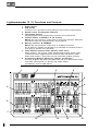
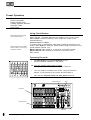
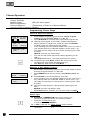
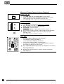
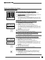
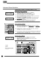
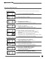
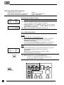
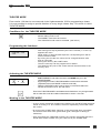
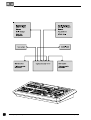
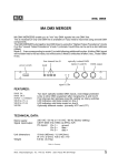
Lightcommander 12 / 2 User´s Manual Version 1.32 June 15., 1995 CONTENTS Overview of Functions 5 Lightcommander 12 / 2: Functions and Controls 6 Preset Operation 8 Using Flash Buttons .......................................................................... 8 Operating Preset-A- ........................................................................... 8 Solo Flash ................................................................................. 9 Operating two Presets (Presets only) ............................................ 9 Selecting Preset Mode ............................................................. 9 Fading between Scenes ........................................................... 9 Channel Flash ........................................................................... 9 Memory Operation (Preprogrammable Scenes) 10 Programming the Memory ................................................................ 10 Toggling from Preset Mode to Memory Mode ....................... 10 Programming Memory ............................................................. 10 Using Manual Masters ....................................................................... 10 Memories .................................................................................. 10 Selecting another Page discreetly .......................................... 10 Dipless Crossfade (Insert Mode) ............................................. 11 Previewing and Editing a Memory .................................................. 11 Previewing a Memory store before setting up the cue .......... 11 Editing a Memory store ............................................................ 11 Programming Memories blind ......................................................... 11 Chaser Operation 12 Programming Chaser Steps ............................................................. 12 Preset as Step (Level Chaser) ................................................ 12 Memories as Step (Memory Chaser) ...................................... 12 Chaser Type ............................................................................. 12 The Chaser Section ............................................................................ 12 Chaser Playback ................................................................................. 13 Auto-Speed Chase (Run Mode) .............................................. 13 Advanced Chaser Playback (Scene Playback) .............................. 14 Manual Step / GO .................................................................... 14 Manual Crossfade .................................................................... 14 Insert Mode ............................................................................... 14 Modify Chase (Modify Chase Steps) ............................................... 15 Editing Steps and Inserting Steps ........................................... 15 Programming steps blind ......................................................... 15 Transferring a Chase to a Memory Master (CTM) ........................ 16 Programming Chase to Memory ............................................. 16 Chase to Memory Playback ..................................................... 16 Preview Chase to Memory ...................................................... 16 2 MA Lighting Technology GmbH . Dachdeckerstr. 16 . D-97297 Waldbüttelbrunn . Fax: + 49 9 31 4 97 94 29 . www.malighting.de Lightcommander 12/2 General Functions 17 Sound to Light .................................................................................... 17 Introduction ............................................................................... 17 Operating Sound to Light ......................................................... 17 Prompt Program Change ......................................................... 17 Remote Step / GO ............................................................................... 17 Switch Channels (Specials 1/2) ....................................................... 18 Introduction ............................................................................... 18 Switch Position ......................................................................... 18 Data Storage on Memory Card ......................................................... 18 Backup ...................................................................................... 18 Save and Load ......................................................................... 18 Exchanging the Battery ........................................................... 18 Overview of Shift Functions ............................................................ 19 Programming Functions ........................................................... 19 Playback Functions: ................................................................. 19 Freezing the Output (Hold) ............................................................... 20 Live / Blind Operation ....................................................................... 20 Theatre Mode ...................................................................................... 21 Operating 24 Channels (Wide Mode) .............................................. 22 Using Upper Channels additionally ......................................... 22 Setting up the 24 Channel Preset ........................................... 22 Cancelling the setting (Grab Release) ................................... 22 Setting up the Output (Channel Presetting) 23 Connecting Desk Channels to DMX Channels .............................. 23 Introduction: DMX Patch .......................................................... 23 Connecting Desk Channels with DMX Channels ................... 23 Indication of DMX Assignment ................................................ 23 Standard Assignment ............................................................... 23 Settings for Analog and DMX Output ............................................ 24 Disable Solo .............................................................................. 24 Select Curve ............................................................................. 24 MIDI Operation 24 Introduction ............................................................................... 24 Linking two Lightcommanders ................................................. 24 Recording to a Sequencer ....................................................... 25 Playing back a MIDI Show with Sequencer ........................... 25 MIDI Format and MIDI Commands ......................................... 26 Important Button Keys 27 Delete All .................................................................................. 27 Lock Preset Mode .................................................................... 27 Lock Programming ................................................................... 27 Blank Chaser Storage indication ............................................. 27 Software Version ...................................................................... 27 eMail: [email protected] . Tel.: + 49 9 31 49 79 40 . User's Manual Lightcommander 12/2 3 Technical Specification 29 Inputs and Outputs (Pinlayout) ....................................................... 29 Safety Instructions 30 Declaration of Conformity 31 INDEX 32 The following symbols are used in this manual: Important Information! Read carefully. Here, a function will be explained more detailed. Hints give a suggestion how to proceed. This asks you to push a button. 4 MA Lighting Technology GmbH . Dachdeckerstr. 16 . D-97297 Waldbüttelbrunn . Fax: + 49 9 31 4 97 94 29 . www.malighting.de Lightcommander 12/2 Overview of Functions eMail: [email protected] . Tel.: + 49 9 31 49 79 40 . User's Manual Lightcommander 12/2 5 Lightcommander 12 / 2: Functions and Controls 1. 2. 3. 4. 5. 6. 7. 8. 1 Power Switch XLR Socket Connector for a gooseneck lamp (Pinlayout see technical specification). Sound control and Switched Channels The Display Section General playback and programming functions are located there. Channel Faders on PRESET -A- (-A- Preset). Master -A- sets maximum output level for all preset channels. Memories and Chase steps are programmed by using Preset-A-. Memory Controls; -B- MEMORY Master -B- sets maximum output level of all Memory masters. All -B- Memory masters are allowed to be switched to Preset-B-Controls. (See page 9; Presets only operation) Flash Buttons (Channel Flash, Memory Flash, Solo) While pressed, the buttons create different flash effects (Flash Light). The flash function toggles between Channel flash and Memory flash. Within both modes, a Solo flash may be performed (sudden change). Programming Buttons (Memories, Chasers and Utilities) You may program 120 Real Level Memories and up to 9000 Chase steps. The Utility menus guide you through the output setups. (Presettings, such as DMX-Patch). 2 3 4 8 9 5 10 6 11 7 15 6 14 13 12 MA Lighting Technology GmbH . Dachdeckerstr. 16 . D-97297 Waldbüttelbrunn . Fax: + 49 9 31 4 97 94 29 . www.malighting.de Lightcommander 12/2 9. The Encoder wheel Selections e.g. Chaser programs or settings of menu modifiers are performed via the big wheel above the Quit button. 10. Soft Buttons and Quit Both soft buttons are selecting displayed functions. Quit cancels each function and switches back to Top-Menu. 11. The Chaser Section Chase steps may run as Auto-Steps (Speed), Sound-Steps (Sound In), or Manual-Steps (Step Button / Manual X Fade). 12. Chaser Mode Buttons You may preselect how a Chase step will be performed. 13. The Master Section Preset-A-Master sets maximum output level for all Preset-A-Channels. (Preset -B-) Memory-B-Master sets max. output level for Memory masters. MAIN Master sets maximum output level for the entire desk. Chaser Master sets maximum output level for Chase steps. 14. Page Button 12 Memory cues are available within each of 10 pages (Page 0-9). 15. Sound to Light / Chase to Memory Sound and Chaser effects are controlled in this section. A detailed description follows later in this manual. About this manual TOP MENU CHASE : 01 STEP : 10 > HOLD < Î TOP-MENU: Appears after switching on the desk. • The preselected Chaser program in on display. • In the lower line HOLD, LIVE and UPPER are indicated to be active, if selected. Notes: • We reserve the right to alter functions without prior notice. • The Lightcommander is designed for use as a lighting control desk only. • All described playback functions can be used together and offer high demanding possibilities in lighting design. • First, familiarize yourself with a function, than go on. eMail: [email protected] . Tel.: + 49 9 31 49 79 40 . User's Manual Lightcommander 12/2 7 Preset Operation Flash button operation Preset operation Using Presets only Fading between Scenes Channel Flash Solo Flash Using Flash Buttons Main Master sets maximum level of Flash buttons. While programming, the Flash buttons select a channel or a Memory number. Memory Flash and Solo: While pressed, individual Memories are added to the current output. When SOLO is selected, Memory flash swaps the output to the selected Memory. Channel Flash and Solo: If Channel flash is preselected, flash adds individual channels to the output. When SOLO is selected, Channel flash swaps the output to the actual flashed channel, only. Master-A-Flash sets Preset-A- to the level of the Main master. Master-B-Flash sets all Memory masters to the level of the Main master. Operating Preset-A• • Set Main Master and Preset-A-Master to full. Adjust individual channels on the preset. Î You can see the output level on stage; The LED´s indicate the brightness of the channels. • You may fade-in and fade-out a scene, using the Preset-AMaster, or just prepare a new scene and than fade-in. • Now test the Channel Flash and Solo Flash functions. Channel Flash Solo Preset A Flash buttons Masters 8 MA Lighting Technology GmbH . Dachdeckerstr. 16 . D-97297 Waldbüttelbrunn . Fax: + 49 9 31 4 97 94 29 . www.malighting.de Lightcommander 12/2 Operating two Presets (Presets only) Selecting Preset Mode P Page number Page button • Hold the Page button and select -P- using the Encoder wheel (the display flashes). Î Preset mode will be auto-selected after 3 seconds. Î Programming memory is disabled. The Chaser section remains fully functional. Fading between Scenes • • Î Î Channel Flash Solo Set Main master and Master -A- to full (set Master -B- to zero). Adjust a scene on Preset -A- and on Preset -B-. Fade between Master -A- and Master -B- (manual Fade). Note: With Preset mode selected, the -B- Memory faders are named as Preset -B-. Channel Flash Î In Preset mode, the Channel flash function is auto-selected. • Use the Flash buttons. The Channel or the entire Preset appears at the output, even if Master -A- and -B- are set to zero. Solo Flash • Select Solo and bump Flash buttons: Î Only the selected Channel appears at the output. (As long as the button is held down, other channels go off). Î You may also use the Autofade Function with Presets. Further details see page 11, "Dipless Crossfade" and page 13, "The Insert Mode". Channel Flash Preset A Solo Encoder wheel Preset B Flash buttons Page button eMail: [email protected] . Tel.: + 49 9 31 49 79 40 . User's Manual Lightcommander 12/2 9 Memory Operation (Preprogrammable Scenes) Programming Memories Memory Playback and Insert Crossfade Preview Memory (Modify Memory) Blind Programming Programming the Memory Toggling from Preset Mode to Memory Mode • Hold Page and select a new Page, using the Encoder wheel, e.g. Page-1-. • Wait 3 seconds. Hence, Memory mode is selected. Î The Page button LED flashes until all Memory faders are set to zero. Î Flash buttons and Solo flash function now as Memory flash. Note: You may use the page button, to skip from page to page (Page up). Use Shift+Page to select page down. Programming Memory • Programming Memory Memory + Flash SEL. MEMORY O8/5 PRESET < SAVE > ALL 2 Select Programming Memory. The Preset scene is indicated by the LED´s, in spite of all Masters being set to zero. • Use a Flash button to select a Memory; if required you may select another Page. • Adjust a scene on Preset-A-. Î Press the Soft key SAVE PRESET to store the preset levels into the Memory. • SAVE All stores the actual output. (Everything visible on stage, including Chaser steps). • Press Quit to return to the Top-Menu. Ready! Using Manual Masters Memories • Set Main master and Master -B- to full (Preset set to zero). • Push up a manual Memory master. Î The Memory appears to be on stage. Selecting another Page discreetly 1 • Push up some manual masters and select a new Page. Î The Memory remains on that page it has been set up from, until the fader is set to zero. • Note: Meanwhile other Memories may be set up from the new Page. Practice using the above functions before going on to the next section. 10 MA Lighting Technology GmbH . Dachdeckerstr. 16 . D-97297 Waldbüttelbrunn . Fax: + 49 9 31 4 97 94 29 . www.malighting.de Lightcommander 12/2 Dipless Crossfade (Insert Mode) Memory X-Fade by using Flash buttons: • Switch off Channel Flash, to release the flash buttons. • Set up Chaser Master and select Insert within the Chaser section. (If a Chaser is running, it stops at the actual step)) • Use the X-Fader to set the required Fade time. Press a Memory flash button. Î The memory fades in at the set time. Each other selected Memory will initiate a Crossfade from one into the next Memory, in order of selection. Î Use the Step button, to achieve a fade between the actual and the previous Memory. Î Switching Insert OFF, causes the Chaser to continue. Note: Chaser Master sets maximum output level of Insert Steps. Manual Memory Crossfade: • Turn on Insert and Manual. • Move the X-Fader from end to end. After fading in a memory (i.e. fader full up or full down), select the next to be faded. • If you don't select a Memory, the previous one is faded in and you can change between both. The Chaser Master controls brightness. Fading out Memories: • Turn Insert off and press the Step button, or use the X-Fader to fade down. (This depends on the kind of Insert mode, you have selected). • Note: If a Chaser was preselected, a Step will be faded in. Inserting Preset A Î Use the Master-A- Flash button to insert the actual scene from Preset-A-. Previewing and Editing a Memory Memory Preview + Previewing a Memory store before setting up the cue • Turn Preview on and select a Memory with the Flash buttons. Î The Memory store is indicated on the LED´s. Preview automatically turns Live mode off (if selected). The consoles output will not be affected. Editing a Memory store Î While previewing, select Modify out of the displayed menu. • Use the Channel fader to "grab" the preprogrammed level. Î Modify as required and save using Quit. Ready! The output will not be affected by this. Programming Memories blind • Turn Live off if it is selected, using the Shift+Live buttons. • Set Master-A- to zero and program as usual. Î The setting on Preset A will not affect the output. NOTE: When the desk is switched to LIVE while editing a Memory this Memory appears at the output. eMail: [email protected] . Tel.: + 49 9 31 49 79 40 . User's Manual Lightcommander 12/2 11 Chaser Operation Chaser Programming Chaser Playback Modify Chaser (Edit and insert steps) Blind Programming Chase to Memory (Transferring a Chase to a Manual Master) Preview Chase to Memory (Modify) Programming Chaser Steps Preset as Step (Level Chaser) CHASE NO. 1O (OO) LEVEL MEMORY STEP: O1 ENTER DELETE FADETIME: 0.00S CONT • Press Chase Programming and select a Chaser program number with the Encoder wheel, e.g. No. 10. • Press LEVEL to proceed with Level Chase Programming. Î Channel levels appear on the LED´s (master independent). • Adjust channels to prepare for a step and save with ENTER. (In Blind mode only Preset levels are stored). • In the following menu the desired FADE time is set. This time is only relevant while the THEATRE MODE is active (see p. 21). The value for new steps is 0.00 seconds. Confirming this value by CONT. DELETE removes one Chase Step. • Turn the Encoder wheel and see the steps appearing on the LED´s. • Use Shift+Live buttons. The steps appears at the output. Î Programming in Live Mode enables the entire output to be recorded as a step (Preset and Memories etc.). • With Quit the desk returns to Top-Menu. Memories as Step (Memory Chaser) • STEP: O1 ENTER MEM: 11/5 DELETE FADETIME: 0.00S CONT Press Chase Programming and turn the Encoder wheel to select a Chaser Program Number e.g. No. O5. • Press MEMORY and select a memory with Memory Flash but tons. Î Press ENTER to record this Memory as a step; In the following menu the desired FADE time is set. This time is • only relevant while the THEATRE MODE is active (see p. 21). The value for new steps is 0.00 seconds. Confirming this value by CONT. Î Turn the Encoder wheel to view the steps appearing on the LED´s. DELETE removes one Memory step. • While Shift+Live is selected, you can view steps on Stage. Chaser Type Î LEVEL or MEMORY show which Chaser type has been programmed within the selected number. • Press the unmarked Soft Key: A menu asks: NEW CHASER? Î If YES is selected, the entire Chaser will be deleted! Dipless Crossfade Theatre Mode 12 p. 11 p. 21 MA Lighting Technology GmbH . Dachdeckerstr. 16 . D-97297 Waldbüttelbrunn . Fax: + 49 9 31 4 97 94 29 . www.malighting.de Lightcommander 12/2 The Chaser Section Î Number: Selection and Preview Chaser (hold button). Note: A Chaser with at least one step, will cause the LED to light, if the Chaser Master is set above 5% level. Step: LED flashes according to the trigger (Step, Speed, Sound). Run Mode: The drawing shows Standard Settings: Brightness, Fade and Speed are set individually. Sound Mode: Bass Step Chase. Manual Mode: Manual Fade between Steps. Insert: Crossfade between Steps and Insert Memories achievable. Chaser Playback Auto-Speed Chase (Run Mode) CHASE NO: 10 (22) TYPE : LEVEL Number Hold button: Previews Chaser Release button: Starts Chaser Shift + Number starts previous Chaser program. Î Turn Insert and Manual OFF. • Select Run (briefly press Sound / Run button two times). The Step button LED flashes with preset Speed. • Set up Chaser Master and set Speed with Speed fader. If required, set X-Fade time with the Crossfader. Î Press and hold Number and select a Chaser program, e.g. Chaser No. 1O. • Auto Preview: The Chaser is indicated on the LED´s. The output will not be affected. Î To START and output the Chaser, release button. • To Restart the Chaser, briefly hit the Number button. Î Stopping a Chase: 1. Set Chaser Master to zero (Chaser continues), or.... 2. Start a Chase without programmed Steps (idling Chaser). (Chaser stops; Number LED remain off). • Select Sound Mode to achieve a Bass Step Chase (Sound In). eMail: [email protected] . Tel.: + 49 9 31 49 79 40 . User's Manual Lightcommander 12/2 13 Advanced Chaser Playback (Scene Playback) Step Manual Step / GO • • Turn RUN OFF and press Step (GO) to recall steps. Steps are fading in with preselected X-Fade time or (using Theatre Mode) with the stored time for this step. Turn RUN ON again: Chase is continued automatically. Manual Crossfade • Turn Manual on and see the Chaser to be stopped. Î Push X-Fader from end to end. Steps appear in the preprogrammed order. Î STOPPING a manual Chase: 1. Set Chaser Master to zero (Fade remains active), or.... 2. Use Number to start a Chaser without preprogrammed Steps. Î Being in manual Playback, you have to fade out Steps manually, also. (Use Step button or manual X-Fader). Insert Mode Changing Steps, Memories and Preset-A-: Turn Insert on and press Step, or....... use the X-Fader, if Manual is selected. • The previous Step is fading in (Insert Step). If a Memory is selected, the Fade toggles between fading in the memory and than the step, again. Î Note: Master-A-Flash enables the entire Preset to be inserted. • Inserting Memories Î Repeat steps as described in chapter "Dipless Crossfade". (See Page 11) 14 MA Lighting Technology GmbH . Dachdeckerstr. 16 . D-97297 Waldbüttelbrunn . Fax: + 49 9 31 4 97 94 29 . www.malighting.de Lightcommander 12/2 Modify Chase (Modify Chase Steps) Editing Steps and Inserting Steps Editing Level Steps (Menu Level Step Programming) • Use the Encoder wheel, to Choose a Step to be modified. The stored levels are indicated on the LED´s. Î Modifying a Channel: Use Channel Fader to "grab" the actual level and alter as required. You may add channels, also. Î ENTER stores every alteration. • In the following menu the desired FADE time is set. This time is only relevant while the THEATRE MODE is active (see p. 21). The value for new steps is 0.00 seconds. Confirming this value by CONT. FADETIME: 0.00S CONT Inserting Level Steps (Menu Level Step Programming) STEP: INSERT • Press Shift to proceed to a further menu. • Adjust the step to be inserted on Preset-A-. Î INSERT adds the step to the existing Chaser. The step is inserted in front of the actual selected one. • In the following menu the desired FADE time is set. This time is only relevant while the THEATRE MODE is active (see p. 21). The value for new steps is 0.00 seconds. Confirming this value by CONT. • DELETE ALL removes all steps. Î Take care with this function: The entire Chaser with all step will be deleted!!! 12 DELETE ALL FADETIME: 0.00S CONT Editing Memory Steps (Menu Memory Step Programming) A memory has to be modified, using Preview Memory. See page 11, "Editing a Memory store". Inserting Memory Steps (Menu Memory Step Programming) STEP: 12 MEM: O2/1 INSERT DELETE ALL FADETIME: 0.00S CONT • Press Shift to proceed to another menu, hence select the memory to be inserted, using the Flash buttons. Î INSERT adds this memory to the existing Chaser. The step is inserted in front of the actual selected one. In the following menu the desired FADE time is set. This time is • only relevant while the THEATRE MODE is active (see p. 21). The value for new steps is 0.00 seconds. Confirming this value by CONT. • DELETE ALL removes all steps. Î Take care with this function: The entire Chaser with all steps will be deleted!!! Programming steps blind • Turn Live OFF if it is selected, using the Shift+Live buttons. Î Set Master-A- to zero and program as usual (Level Step). NOTE: While programming memory steps, there is no need to set Master-A- to zero. The desk´s output will not be affected! eMail: [email protected] . Tel.: + 49 9 31 49 79 40 . User's Manual Lightcommander 12/2 15 Advanced Chaser Operation: Transferring a Chase to a Memory Master (CTM) Programming Chase to Memory CHASE TO MEMORY > SELECT MEMORY < 1O/6 CHASE: 10 LEARN 1.OOS BASS • Use Shift + CTM buttons and select a Memory (Flash button with red and yellow LED´s) • Use Encoder wheel to select a Chaser program. Î The Chaser appears to be indicated on LED´s: Watch this Auto Preview, to ensure the right Chase selection. Î Auto Preview will not affect the output. • Set Speed, using LEARN to step ahead at the required rate, or, hold down LEARN and adjust speed via Encoder wheel. Î Press Quit to store setup. The yellow LED flashes according to the preset rate. (If Sound is selected, according to Bass Rhythm). Chase to Memory Playback • Push up the assigned Memory Master to fade in the Chaser. You may use the Flash button, if Channel Flash and Insert Mode are selected to be OFF. Î Pushing Flash, or setting up the fader from zero, will cause a Restart of the Chaser in the Memory. Î On each page, 4 Chases with different speeds may be programmed. Including a Chase in the Chaser section, altogether five Chasers are allowed to be run simultaneously. Preview Chase to Memory 1O/ 2 NO O2 LEARN O.25S BASS • • Turn Preview on and press Memory Flash Button. The Chaser appears on the LED´s. Speed may now be set directly via the Encoder wheel. (Single handed operation). Note: If Shift+Live buttons are used, the chaser appears at the output. 16 MA Lighting Technology GmbH . Dachdeckerstr. 16 . D-97297 Waldbüttelbrunn . Fax: + 49 9 31 4 97 94 29 . www.malighting.de Lightcommander 12/2 General Functions Sound to Light Remote Step Switch Channels Store Programs to Card Overview of Shift Operation Freeze Output Live / Blind Operation 24 Channel Operation Theatre Mode (Specials) (Backup) (Hold) (Upper Channels) Sound to Light Sound to Light Introduction • Within the Sound to Light mode, the levels of Memories 9-12 are controlled by the audio input (Sound In). Signal input will be split into three frequency ranges; • -B- ; -M- ; -T- ; Bass, Mid and Treble are controlling the associated Memories, depending on input volume. • -P- = Pause; this Memory is inverse proportional to input volume. (I.e. audio off causes the memory to be on) Î The Memory Masters set maximum output of audio triggered Cues. (100% when set to mid position) Operating Sound to Light • Feed Sound IN socket with an audio input. Turn Sound control up, until the LED flashes with Bass Rhythm. Î Turn Sound to Light on and set the four Sound to Light Memories to neutral position. Observe playback and readjust brightness, if required. Prompt Program Change • Press Page briefly. Î This four Memories achieve a sudden change of page. (There is no need to set Faders to zero, beforehand) Remote Step / GO • Manual Sound Step Mode Use Number to load a Chase into the Chaser (RUN OFF). • Insert a Foot switch into the Remote Step input. Î The Chaser jumps one step ahead, each time the contact is closed. Simultaneous Sound Steps possible. (Compare with page 13, "Chaser Playback"). eMail: [email protected] . Tel.: + 49 9 31 49 79 40 . User's Manual Lightcommander 12/2 17 Switch Channels (Specials 1/2) Introduction • Specials 1 and 2 are two additional channels. They are operated independently of the desk and wired directly to the analog output. (Can be patched, using DMX. See page 23, "DMX-Patch) Switch Position • OFF or full ON (Analog output: 0/+10 VDC). Î With both Analog Outputs, Fog Machines or other effects with 0 10 Volts Operation may be controlled directly. Î Attention: You can only control equipment that has no voltage at it's input (in no case 230 V). Data Storage on Memory Card MEMORY Backup • CARD • Using a Memory Card enables you, to create a personal library of lighting plots. Different programs can be easily loaded into the desk. A backup is also a security copy of your work. Accidentally deleted programs can be retrieved easily by loading the backup from card. Save and Load OVERWRITE YES CARD? NO • Put the Memory Card into the slot, located above the Programming buttons. Follow the instructions in the display. Exchanging the Battery • Renew battery, if the display shows a voltage below 2.3 V. (or after approx. 2 years, at the latest). Î Load the program from card into the desk, exchange battery, and save to card again. 18 MA Lighting Technology GmbH . Dachdeckerstr. 16 . D-97297 Waldbüttelbrunn . Fax: + 49 9 31 4 97 94 29 . www.malighting.de Lightcommander 12/2 Overview of Shift Functions Playback Functions: SHIFT PAGE Î Counts one page backwards (Page down). + SHIFT NUMBER Î Starts the previous run Chaser. + SHIFT HOLD Î Freezing the desk´s output. • New settings do not affect the output. A detailed description follows later in this chapter. + SHIFT LIVE Î Activates Live Operation. • Programmed storage is output onto stage. A detailed description follows later in this chapter. + SHIFT UPPER + SHIFT Note: As long as "Shift" is held, each Shift Function may be selected one after another. PRESETFLASH + Î Swaps Channels 1-12 with Channels 13-24. • Setting up scenes with 24 channels by toggling between Upper and standard. Modifying channels by "grabbing" the actual level. • Cancelling a setting: Using Shift+Preset Flash sets all levels to zero. Quit sets levels to the actual fader setting. A detailed description follows later in this chapter. Programming Functions SHIFT CTM Î Menu: Programming Chase to Memory A detailed description will be found on page 16. (Chase to Memory Master transfer) SHIFT Î Menus: Programming Chaser Steps • A further menu appears; Steps may be inserted, or the entire Chaser may be deleted (see page 15). + PROGRAMMING CHASER STEP SHIFT UTILITY 2 + SHIFT SOUND RUN + Î Activating the THEATRE MODE see page 21 Î Special Menus to adjust output channels. For a detailed description see page 22: "Setting up Output Channels" Î Switching the desk from SOUND to MANUAL Function analogue to SOUND/RUN, but the other way round eMail: [email protected] . Tel.: + 49 9 31 49 79 40 . User's Manual Lightcommander 12/2 19 Shift Operation while Playback: Output Freeze Function Live / Blind Operation; the difference Wide Mode; 24 Channel Operation (Hold) (Live / Blind Operation) (Upper Channels) Freezing the Output (Hold) SHIFT HOLD + SET MAIN TO ZERO CANCEL You want to set up an entirely different setting on desk, discretely? • Press Shift + Hold buttons. Î The desk´s output is frozen, now. Any action will not affect outputs. You may prepare each new setting, discretely. • Sudden Release: Press CANCEL to skip to the new setting. • Crossfading to a new setting: Set Main Master to Zero and push it back to Full again. Î Hold is auto-released, when Main is set to full. Live / Blind Operation BLIND: • NOTE: Blind is the Standard setting. Î Previewed Memories, auto-previewed Chases and Chases being selected while programming, will be indicated ON LED´s exclusively. • This enables discrete Editing and Modifying, even during the show takes place, without any affect on the outputs. LIVE: SHIFT LIVE + Î Previewed Memories, auto-previewed Chases and Chases being selected while programming, will appear ON STAGE. Note: Only the selected program remains visible, if the Main Master is set to zero. Î Note: Preview auto selects Blind Operation. Turn on Live afterward selecting preview to see the memory store live on stage. Overview: Shift Functions while Playback. 20 MA Lighting Technology GmbH . Dachdeckerstr. 16 . D-97297 Waldbüttelbrunn . Fax: + 49 9 31 4 97 94 29 . www.malighting.de Lightcommander 12/2 THEATRE MODE From version 1.26 there is one new mode in the Lightcommander 12/2 for programming a chaser. It is now possible to assign a special fadetime to every single chaser step. This mode is called THEATRE MODE. Conditions for the THEATRE MODE - The chaser may not run by sound or automatically Manual fading must be off The INSERT mode must be inactive The THEATRE mode must be activated (see below) Programming the fadetimes FADETIME: 0.00S CONT - After saving one step by ENTER (see user´s manual p. 12 and 14) appears this menu While editing of programmed steps the corresponding time will be shown instead of 0.00 By turning the encoder the value can be changed between 0.00 and 10.0 seconds Storing the value by the CONT button Then the next step can be programmed or edited The fadetimes are part of the chaser and will be saved also to the memory card. Activating the THEATRE MODE SHIFT UTILITY 2 + - SHIFT +UTILITY" and within the next menu MORE leds you to the THEATRE MODE By pressing the button THEATRE MODE this mode will be activated (stripebefore the word "MODE" indicates mode ON) While the THEATRE mode is active, there is a vertical line within the squares of the lower row in the main menu Even if the THEATRE MODE is activated as described above, any changes made will not take effect until all conditions described in section 1 are met! Working in the THEATRE MODE - As soon as all mentioned conditions are fulfilled, for the NEXT step the times saved according to 2. are relevant; the times adjusted by the XFADE fader are invalid. - By moving the XFADE fader changing of the actual fade time is possible. The fader will be fixed at the given value (grab, analogue to editing of memories). - After inactivating the THEATRE mode by the criterion mentioned above the actual fade will be finished using the value set by the XFADE fader. eMail: [email protected] . Tel.: + 49 9 31 49 79 40 . User's Manual Lightcommander 12/2 21 Operating 24 Channels (Wide Mode) Using Upper Channels additionally SHIFT UPPER + The Lightcommander deals with 24 channels permanent. Î Using Shift + Upper buttons activates channels 13-24. Î Each Setting, Programming or Selecting function now relates to channels 13-24, including Flash functions. • You may program or modify memories or Level chase steps, containing a selection out of 24 channels. Î Flash buttons function the same in standard mode as in upper mode (e.g. selecting channels while using DMX-Patch. See facing page). Setting up the 24 Channel Preset • Adjust a selection out of channels 1-12 as required. Î Use Shift + Upper to access the channels 13-24. • "Grab" the actual indicated level (If zero, just push up the fader) and set channel levels as required. Î Modifying a channel later is performed in the same manner. Set the Channel Fader to the indicated output level to "grab" the level to be modified and readjust brightness as required. Cancelling the setting (Grab Release) SHIFT PRESETFLASH + Î Using Shift + Preset Flash sets every level of all preset Channels to zero. • You may "grab" channels at zero individually to adjust a new setting. Another way is to cancel all auto-functions while pressing Quit. The levels skip back to the actual Fader Position. UPPER CHANNELS The desk simulates 12 further Channel faders and Flash buttons to select channels. Flash buttons are toggled else! 22 MA Lighting Technology GmbH . Dachdeckerstr. 16 . D-97297 Waldbüttelbrunn . Fax: + 49 9 31 4 97 94 29 . www.malighting.de Lightcommander 12/2 Setting up the Output (Channel Presetting) How to connect desk channels with DMX channels How to prevent channels to be dimmed by Solo How to match dimming levels of different lamps (DMX Patch) (Disable Solo) (Select Curve) Connecting Desk Channels to DMX Channels {{{{ Introduction: DMX Patch Î DMX Patch will not affect the analog output! The DMX output controls the DMX channels 1-99. DMX Patch enables the connection of each desk channel with up to four DMX channels. This function may be especially interesting when dealing with different stages, when using motorized equipment and colour changers and also in case of Dimmer failure. Within Standard Assignment the Desk Channels 1-26 are connected to the DMX Channels 1-26 (other channels are open). Connecting Desk Channels with DMX Channels DMX PATCH SELECT MIDI • • Press Utility 1 and select DMX PATCH. Use Flash button to select a Desk Channel and turn Encoder wheel to select a DMX Channel. Î You can view the selected DMX Channel appearing at the output, by switching the desk to Live Operation (Shift+Live). • To assign channels press CONNECT. Î CONNECT shows the channels which are connected. You may verify this, by pushing up the associated channel fader. Indication of DMX Assignment CH O3 > O3 17. CONNECT OPEN SHIFT DMX PATCH + • CONNECT • CONNECT: • OPEN Actual display; this DMX channel is connected to the indicated Desk channel. This DMX channel is connected to another Desk channel. This DMX channel is NOT connected. Standard Assignment • Shift proceeds to another menu: ALL 1 : 1: Desk channels 1-26 control DMX channels 1-26. Î ALL CLEAR opens each connection! Î Use this function only if a new patch setting is required, or save the actual setting to card, before continuing. eMail: [email protected] . Tel.: + 49 9 31 49 79 40 . User's Manual Lightcommander 12/2 23 Settings for Analog and DMX Output Disable Solo SHIFT UTILITY 2 + CH 12 > DISABLED DISABLE ENABLE You want appointed channels to remain on, while using Solo Flash? Press Shift + Utility 2 and select DISABLE SOLO from the menu. Select Channels with Flash Buttons or with Encoder wheel and set as required (Standard: All Enabled). Î A channel indicated as DISABLED remains on while using Solo Flash. There is no difference between Memory Solo or Channel Solo. • • Î Shift proceeds to a further Menu. ALL DISABLED or ALL ENABLED swaps function of all channels simultaneously. Select Curve While using projectors with different lamp bulbs, it may occur, that brightness differs, although faders are set to the same level. You may get a similar effect, if you operate dimmers from different manufacturers, or with differing technology. SHIFT UTILITY 2 + CH 12 > LINEAR CURVE LINEAR Î Match this by setting the darker channels to Curve. (Increases the lower setting range). • Press Shift + Utility 2 and press SELECT CURVE as indicated on display. • Select channels by flash buttons or Encoder wheel and toggle them to CURVE if required (Standard: All Linear). Î Shift proceeds to a further Menu. ALL CURVE or ALL LINEAR swaps function of all channels simultaneous. Note: This function has no influence on brightness of LED´s. 24 MA Lighting Technology GmbH . Dachdeckerstr. 16 . D-97297 Waldbüttelbrunn . Fax: + 49 9 31 4 97 94 29 . www.malighting.de Lightcommander 12/2 MIDI Operation Introduction MIDI enables you to link several Lightcommanders, by connecting the MIDI OUT Socket of a desk to the MIDI IN socket of another desk. By means of this, Memories with Page and Chaser Programs with mode (Manual Step, Sound Step, or Speed) are transferred. While programming linked desks, you have to prepare settings on each desk simultaneously. Other Operations: An entire show can be recorded to a sequencer, using MIDI OUT. Later, this show can be played back from sequencer, using MIDI IN. Linking two Lightcommanders • • • • Set all Masters to zero. Connect MIDI OUT of the main desk with MIDI IN of another desk. Press Utility 1 buttons and SELECT MIDI function in the display. Select same MIDI Channel on both desks and select MIDI IN on the receiver desk FIRST. HENCE, turn MIDI OUT on at the main desk! Î The sign MIDI appears in the Top Menu to indicate mode of operation. • Push up the Main Master at the receiver desk and set Masters of main desk as required. The maximum output level of the receiver desk is set by its own Main Master, other masters are controlled by the main desk. Î After the desks have been programmed simultaneously, Memories and Chasers can be played back by the main desk controls. Recording to a Sequencer • • Connect MIDI OUT to the MIDI input of the sequencer. Press Utility 1 and SELECT MIDI. Set same MIDI Channel for both, Lightcommander and sequencer. Î First, start the Sequencer ("Record"). • Turn MIDI OUT on at the Lightcommander. Î The Sequencer is recording Memory and Chaser playbacks. (Individual channels will not be recorded) Playing back a MIDI Show with Sequencer • Connect MIDI IN of the Lightcommander to the Sequencer output. • Select MIDI Channel and turn MIDI IN on. Î Start the Sequencer. The earlier recorded Show will be played back automatically. The show can be synchronized with other MIDI Equipment. Î On the following page you will find detailed informations about the MIDI Format and the transferred commands. eMail: [email protected] . Tel.: + 49 9 31 49 79 40 . User's Manual Lightcommander 12/2 25 MIDI Format and MIDI Commands Î MIDI exclusively deals with Controller Commands. In the MIDI menu two different sets of controller commands can be activated. Press Shift button within the MIDI menu. • While MIDI OUT is turned on, all fader settings (Masters), memory buttons, the page and Chaser Program Numbers will be transferred, to initiate MIDI. • While MIDI IN is turned on or off, each internally activated Memory, the Chaser and Insert Fades will be removed. • When MIDI IN is turned on, the Main Master, the Preset-A and -B master will be turned to 100 %. The chaser master is set to 0 %. Î Commands: The Status Byte to be transferred is always the Control Change Command. = 1011nnnn (Bn hex) (nnnn=MIDI Channel). Hence, two Data bytes are following: Name: Memory Fader 1 Memory Fader 2 Memory Fader X Memory Fader 12 Main Master Fader Preset A Master Preset B Master Chaser Master 1. 00 01 XX 11 17 18 19 20 (102) (103) (XX) (113) (119) (120) (52) (53) Memory button 5-8 Memory button 1-4 Memory button 9-12 Page 0-9 Solo Function 23 24 26 27 28 (54) (55) (57) (58) (59) Chaser Start (+No.) Chaser Step button Preset Mode ON X-Fader X-Fade Insert X-Fade Manual Preset Flash buttons 32 33 48 49 50 51 52 (63) (20) (29) (30) (31) (84) (85) +08=Mem5 04=Mem6 02=Mem7 01=Mem8 +08=Mem1 04=Mem2 02=Mem3 01=Mem4 +08=Mem9 04=Mem10 02=Mem11 01=Mem12 +00-09 (Page 0 9) +16=Channel Flash 08=Zero +04=Memory Flash 02=Preset B Flash +01=Preset A Flash +00-98 (Chaser number) +00-XX (value doesn´t matter) +00-XX (value doesn´t matter) +00-127 (Fader level) +00 = ON, 00 = OFF (unequal zero) +00 = ON, 00 = OFF (unequal zero) +04=Preset A 02=Preset B 01=Zero Sound Sound Sound Sound Sound 53 54 55 56 57 (86) (87) (88) (89) (90) +00 = ON, 00 = OFF +00-127 (Fader level) +00-127 (Fader level) +00-127 (Fader level) +00-127 (Fader level) 58 59 (70) (71) +00-127 (Fader level) +00 = Sound, 01 = Run, 02 = Manual to to to to to Light Mode Light Pause Light Bass Light Mid Light Treble Chaser Speed Fader Chaser Mode 2. Data byte: +00-127 (Fader +00-127 (Fader +........... +00-127 (Fader +00-127 (Fader +00-127 (Fader +00-127 (Fader +00-127 (Fader level) level) level) level) level) level) level) (unequal zero) Numbers in brackets are the values for the second controller set. 26 MA Lighting Technology GmbH . Dachdeckerstr. 16 . D-97297 Waldbüttelbrunn . Fax: + 49 9 31 4 97 94 29 . www.malighting.de Lightcommander 12/2 Important Button Keys Deleting the entire stored programs Freezing the Two Presets Mode Programming disabled Indicating the Chase storage Indicating the Software Version (Delete All) (Lock Preset Mode) (Lock Programming) (Blank Chase Storage indication) (Software Version) These following five functions are available, if the desk is turned off and the respective buttons are pressed and held down, while turning on the desk again. Î Observe the display and hold the buttons until the menu is displayed! Delete All Î Press and hold Soft A + Soft B + Quit. Î YES deletes all Memories and Chasers. Presettings will be set to Standard. (Patch: 1 :1; Solo: All Enabled; Curve: All Linear) Lock Preset Mode Î Press and hold Hold + Live + Upper. Î YES activates the Preset Mode and locks Page. Undo: Repeat proceeding, hence press NO. Lock Programming Î Press and hold Memory + Chase + Utility 1. Î YES locks Programming, Backup and the function MODIFY available within Preview Menu Undo: Repeat proceeding, hence press NO. Blank Chaser Storage indication Î Press and hold Preview + Soft A + Soft B. On display are the remaining steps to be programmed. Upon release of the buttons, the desk returns to Top Menu. Software Version Î Hold both Soft Buttons, while turning on the desk. eMail: [email protected] . Tel.: + 49 9 31 49 79 40 . User's Manual Lightcommander 12/2 27 28 MA Lighting Technology GmbH . Dachdeckerstr. 16 . D-97297 Waldbüttelbrunn . Fax: + 49 9 31 4 97 94 29 . www.malighting.de Lightcommander 12/2 Technical Specification Inputs and Outputs (Pinlayout) 1. Power Input: The rated voltage is 230 V Alternating Current (50 Hz). Î The mains supply compensates voltage fluctuations between 180 and 240 VAC. Î Attention! To meet the security standards, the desk must be operated with grounded Power outlets! 2. Analog Output; 0-10 V positive direct current: The control signal is output at a 15-PIN SUB-D Socket. Pinlayout: Pin 1 -12 Channel 1 -12 Pin 13 -14 Channel S1 -S2 Pin 15 Ground (Earth) 3. DMX Output: The DMX Output meets USITT DMX 512 (1990) Standard. The Lightcommander can control each equipment, meeting this standard. Pinlayout: Pin 1 = Ground Pin 4 = not connected Pin 2 = Data Pin 5 = not connected Pin 3 = Data + 4. Sound input (Sound In): A RCA socket is used to feed an audio signal. An input transformer is used to isolate the input. Impedance approx. 1 kOhm. Î The input needs a minimum voltage feed of approx. 100 mV to be operative. Setting: Turn Sound input control until the LED flashes with Bass Rhythm. 5. Remote Step (Remote GO): Use a 1/4 inch Jack, to connect a foot switch to the desk. Having contact, the Chaser proceeds one Step ahead. 6. MIDI IN / MIDI OUT: The MIDI Interface meets M I D I Standard. 6 7. 2 3 4 5 1 3 Pin XLR Socket for a desk lamp: Pinlayout: Pin 1 = not connected Pin 2 = Ground Pin 3 = 12 VDC Î Note: Subject to change without notice. eMail: [email protected] . Tel.: + 49 9 31 49 79 40 . User's Manual Lightcommander 12/2 29 Safety Instructions: 1. 2. 3. 4. Read all the instructions in the user´s manual. Keep the user`s manual for later use. Follow all the instructions on the unit. Pull the plug before cleaning the unit; don't use any liquid or spray cleaner. Clean with a damp cloth. 5. Don´t use the unit near water. 6. Don't´ put the unit on unstable tables etc.. It might fall down and get damaged. 7. There are slots in the case for aeration; don't cover these slots up because they guarantee the reliable use of the unit and protect it against overheating. Don´t install the unit into a frame unless sufficient aeration is guaranteed. 8. The unit is provided with a safety plug. This plug can only be used with safety sockets. These safety measures should by all means be followed. In case the plug doesn't fit into the socket (e.g. with old sockets), the socket should be replaced by an electrician. 9. Don´t put any objects on the wire and make sure nobody steps on it. 10. In case you use an extension wire make sure the sum of the power consumption of the connected units does not exceed the maximum power of the wire. The sum of the units plugged in the socket should not exceed 10 Ampere. 11. Don´t spill any liquid over the unit. Don´t put any objects through the slots of the unit, as these might get in contact with parts that are live or might cause short circuits. This may cause fires and shocks. 12. Don´t service the unit yourself as parts that are live might be exposed when you open the case; you run the risk of getting shocked. All services should only be carried out by a specialist. 13. If one of the following conditions occurs, please pull the plug out and call the service: A. Wire or plug is damaged or worn. B. Liquid got into the unit. C. The unit was exposed to rain or got damp. D. The unit doesn´t work properly even if you follow the instructions of the user´s manual. E. The unit fell down and the case was damaged. 14. Only use wires which are marked safety proof. 15. Don´t use any high-power walkie-talkies near the unit. 30 MA Lighting Technology GmbH . Dachdeckerstr. 16 . D-97297 Waldbüttelbrunn . Fax: + 49 9 31 4 97 94 29 . www.malighting.de Lightcommander 12/2 DECLARATION OF CONFORMITY according to guide lines 89/336 EWG and 92/31 EWG: Name of producer: Address of producer: MA Lighting Technology GmbH Dachdeckerstr. 16 D-97297 Waldbüttelbrunn declares that the product Name of product: Type: MA Lightcommander 12/2 LC 12/2 answers the following product specifications: Safety: EN60065, VDE0860, IEC65 EMV (EMC): EN55103-1 (E1), EN50081-1 EN55103-2 (E2), EN50082-1 Additional information: All DMX512 and analogue inputs and outputs must be shielded and the shielding must be connected to the ground and the case of the corresponding plug. Waldbüttelbrunn, 17.01.1995 Dipl. Ing. Michael Adenau eMail: [email protected] . Tel.: + 49 9 31 49 79 40 . User's Manual Lightcommander 12/2 31 INDEX A F Advanced Chase Operation 16 Advanced Chase Playback 14 Insert-Mode 14 Inserting Memories 14 Manual Crossfade 14 Manual Step / GO 14 Flash Buttons 8 Freezing the Output (Hold) B G General Functions Grab Release 22 17 Backup 18 Blind 20 H C I Channel Presettings 23 Channel-Flash 8, 9 Chase 15 Chase Program 12 NEW CHASE? 12 Number 12 Chase Steps 15 Editing Level Steps 15 Editing Memory Steps 15 Inserting Level Steps 15 Inserting Memory Steps 15 Programming steps blind 15 Chase to Memory 16 Chase to Memory Playback 16 Preview Chase to Memory 16 Programming Chase to Memory 16 Chaser Operation 12 Mode 13 Chaser Playback 13 Auto-Speed 13 Run-Mode 13 Sound Mode 13 X-Fade Time 13 Chaser Section 13 CONNECT 23 Connecting Desk-Channels to DMXChannels 23 Important Button Keys 27 Insert-Mode 11, 14 Inserting Memories 14 Inserting Steps 15 D Data Storage on Memory Card 18 Dipless Crossfade 11 Disable Solo 24 DMX-Patch 23 Connecting Desk-Channels with DMX-Channels 23 DMX-Assignment 23 Introduction 23 20 Hold 20 L Level-Chase 12 Linking 25 Live 20 Live / Blind Operation 20 M Master-Section 7 Memory Operation 10 Dipless Crossfade 11 Editing a Memory 11 Insert-Mode 11 Memory-X-Fade 11 Previewing a Memory 11 Memory Playback 10 Memory-Card 18 Backup 18 Exchanging the Battery 18 Save and Load 18 Memory-Chase 12 Memory-Flash 10 MIDI Operation 25 Introduction 25 Linking two Lightcommander 25 MIDI Format and MIDI Commands 26 MIDI-Show with Sequencer 25 Recording to a Sequencer 25 Modify Chase 15 E Editing a Memory 11 Editing Steps 15 32 MA Lighting Technology GmbH . Dachdeckerstr. 16 . D-97297 Waldbüttelbrunn . Fax: + 49 9 31 4 97 94 29 . www.malighting.de Lightcommander 12/2 O T OPEN 23 Operating 24 Channels 22 Operating Preset-A8 Operating two Presets 9 Channel-Flash 9 Fading between Scenes Preset-Mode 9 select -P9 Solo-Flash 9 Technical Specification 29 Inputs and Outputs 29 Pinlayout 29 XLR-Socket for a desk lamp Theatre Mode 21 9 P Page 10 Preset Operation 8 Presets only 9 Preview 11 Preview Chase to Memory 16 Previewing a Memory 11 Programming Chase-Steps 12 Level-Chase 12 Memories as Step 12 Memory-Chase 12 Preset as Step 12 Programming Memories blind 11 Programming steps blind 15 Programming the Memory 10 Memory-Mode 10 Programming Memory 10 Save All 10 Save PRESET 10 select a Page 10 29 U Upper Channels 22 Using Flash Buttons 8 Channel-Flash 8 Master-A-Flash 8 Master-B-Flash 8 Memory-Flash 8 Solo 8 Using Manual Masters 10 Utility 1 23 Utility 2 24 W Wide Mode 22 Cancelling the setting 22 Grab Release 22 Setting up the 24-ChannelPreset 22 Using Upper Channels 22 X X-Fade 13 R Remote Step / GO 17 S Save and Load 18 Scene Playback 14 Select Curve 24 Setting up the Output 23 Settings for Analog- and DMX-Output 24 Disable Solo 24 Select Curve 24 Shift-Functions 19 Solo 8, 9, 10 Sound to Light 17 Introduction 17 Operating Sound-to-Light 17 Prompt Program-Change 17 Specials 1/2 18 Stopping a Chase 13 Survey of Shift-Functions 19 Switch-Channels 18 Introduction 18 Switch Position 18 eMail: [email protected] . Tel.: + 49 9 31 49 79 40 . User's Manual Lightcommander 12/2 33 34 MA Lighting Technology GmbH . Dachdeckerstr. 16 . D-97297 Waldbüttelbrunn . Fax: + 49 9 31 4 97 94 29 . www.malighting.de Lightcommander 12/2 eMail: [email protected] . Tel.: + 49 9 31 49 79 40 . User's Manual Lightcommander 12/2 35 Lightcommander 12/2 User's Manual Version 1.32