1
NAVAL POSTGRADUATE SCHOOL
Monterey, California
THESIS
USING SOLID MODELING TECHNIQUES
TO CONSTRUCT THREE-DIMENSIONAL ICONS
FOR A VISUAL SIMULATOR
by
Jane Stolarski Polcrack
September 1991
Thesis Co-Advisors:
Approved
for public release; distribution
Michael J. Zyda
David R. Pratt
is
unlimited.
—
ECURITY CLASSIFICATION OF THIS PAGE
REPORT DOCUMENTATION PAGE
la.
REPORT SECURITY cLASSIMCAIION
2a
SECURITY CLASiJII-ICATioN authority
E D E CLASS
IP ICA TI
OWUOWNfiHAP
I
Nfi
^RES T RIC TI VE MARK NGS
UNCLASSIFIED
I
DISTRIBUTIONS VAILABILITY OF report
Approved for public release;
3.
SCHEDULE
distribution is unlimited
performing ORGANIZATION REPORT NUMBER(S)
4.
1
nam^ of gg^bftMiNG ORGANIZATION
6b.
Computer Science Dept.
OFFICE SVMBOL
(if
ADDRESS
Monterey,
8a.
(City, State,
CA
and ZIP Code)
ADDRESS
8c.
NAME OF MONI T ORING ORGANIZA TI ON
Naval Postgraduate School
7b.
ADDRESS (City, State, and ZIP Code)
Monterey, CA 93943-5000
93943-5000
NAME OF FUNDING/SPONSORING
ORGANIZATION
(City, State,
Sb.
OFFICE SVMBOL
(if
numbers
7a.
applicable)
cs
Naval Postgraduate School
6c.
Monitoring organization report
1
5.
5!
PROCUREMEN T NS T RUMEN T
I
I
DENT
I
FI
CA TI ON NUMBER
applicable)
it. SOURCE OF FUNDING NUMBERS"
PROGRAM
PROJECT
TASK
ELEMENT NO.
NO
NO
and ZIP Code)
WORK
UNIT
ACCESSION NO
TITLE (Include Security Classification)
11.
USING SOLID MODELING TECHNIQUES TO CONSTRUCT THREE-DIMENSIONAL ICONS FOR A VISUAL SIMULATOR (U)
12. PERSONAL AUTHOR(S)
Polcrack, Jane Stolarski
15 PAGE COUN T
TIME COVERED
14. DATE OF REPORT (Year, Month. Day)
September 1991
from 08/89 to 09/91
64
16. supplementary NOTATiorrhe views expressed in this thesis are those of the author and do not retlect the official
policy or position of the Department of Defense or the United States Government.
13a. TYPE 0£REP.0RT
Master sThe
lesis
18.
COSATI CODES
17.
GROUP
FIELD
1
ttb.
9.
SUBJECT TERMS
(Continue on reverse
if
necessary and
identify
by block number)
icon,constructive solid geometry, modeling, computer graphics
SUB-GROUP
ABSTRACT
(Continue on reverse if necessary and identify by block number)
Realistic three dimensional (3D) models are an essential part of
to the quality
of the scenarios and the decision making training the
They contribute greatly
system can provide. Commercial programs are
any
battle simulator.
and modify these models, also known as icons, but they tend to be very expensive and complicated.
They also tend to be very specific as to the file format used to store icons. The developers of the Naval Postgraduate
School's battle simulator, NPSNET, need a simple, easy to use, and inexpensive system which allows them to quickly
build and modify icons stored in Object File Format (OFF). We present the program NPSICON to meet this need and
also discuss some of the issues involved in building 3D icons. NPSICON runs on commercially available Silicon
Graphics, Inc. IRIS workstations.
available to build
it.
DIS T R BU TI ON/A VA
I
I
LAB
I
LI T
V
Q UNCLASSIFIED/UNLIMITED
22a.
O F ABS T RAC T
[~J
SAME AS
RPT.
i\.
Q DTIC USERS
nam£ OF RESPONSIBLE INDIVIDUAL
ABSTRACT SECURITY CLASSIFICATION
UNCLASSIFIED
22b.
TELEPHONEj/nc/ude Area Code)
(408) 646-2305
DD FORM
1473, 84
MAR
83
APR edition may
All
be used
until
exhausted
other editions are obsolete
wm
E
SVMBOL
SECURITY CLASSIFICATION OF THIS PAGE
UNCLASSIFIED
Approved
for public release; distribution
is
unlimited
USING SOLID MODELING TECHNIQUES
TO CONSTRUCT THREE-DIMENSIONAL ICONS
FOR A VISUAL SIMULATOR
by
Jane Stolarski folcrack
Captain, United States
BBA,
St.
Army
Bonaventure University, 1983
Submitted
in partial fulfillment
of the
requirements for the degree of
MASTER OF SCIENCE
IN
COMPUTER SCIENCE
from the
NAVAL POSTGRADUATE SCHOOL
September 1991
ABSTRACT
Realistic three dimensional (3D)
They contribute
models are an essential
part of
any
greatly to the quality of the scenarios and the decision
battle simulator.
making
training the
system can provide. Commercial programs are available to build and modify these models,
also
known
as icons, but they tend to be very expensive
be very specific as to the
file
format used
Postgraduate School's battle simulator,
and complicated. They also tend
to store icons.
NPSNET, need
The developers of
Format (OFF). We present the program
some of
the issues involved in building
NPSICON
3D
icons.
available Silicon Graphics, Inc. IRIS workstations.
in
to
the Naval
a simple, easy to use, and
inexpensive system which allows them to quickly build and modify icons stored
File
to
meet
this
NPSICON
in
Object
need and also discuss
runs on commercially
/4ji
TABLE OF CONTENTS
I.
II.
in.
IV.
V.
INTRODUCTION
1
A.
FOCUS
1
B.
CHAPTER SUMMARY
2
OTHER 3D ICON MODIFICATION/GENERATION SYSTEMS AT NPS
3
A.
3DSHIPS
3
B.
PREVIEW
5
OVERVIEW OF NPSICON AND
ITS
USE
8
GOALS
A.
INITIAL
B.
OVERVIEW
TECHNIQUES USED
8
9
IN
NPSICON
10
A.
LIGHTING
B.
OBJECT FILE FORMAT
C.
THE NPS PANEL DESIGNER AND TOOLBOX NPSPD
10
(OFF)
1
-
IMPLEMENTATION SPECIFICS
1
14
A.
PICKING VS. RAY TRACING
14
B.
ATTACHING PARTS
15
C.
LOADING FILES
16
D.
STORING FILES
17
E.
ROTATION
17
F.
SCALING
17
G.
TRANSLATION
17
IV
MOBVI.
NPSICON LIMITATIONS AND FUTURE DIRECTIONS
A.
LIMITATIONS
B.
VII.
Added
Orientation of Parts to be
2.
Ability to Rotate, Scale, and Translate
to an Icon
Any
18
Part
AnyTime
18
3.
Stepping through Polygons by Part or Entire Icon
19
4.
Changing the Color of Individual Polygons
19
5.
Including Color and Materials
6.
Adding Individual Polygons
19
7.
Decaling
19
8.
Problems with the
When
Window Manager
FUTURE DIRECTIONS
Creating Sub-Icons
19
20
20
1.
Efficiency Considerations
20
2.
NPSICON
20
3.
Portability Considerations
Design Considerations
CONCLUSIONS
APPENDIX
LIST
18
1.
in an Icon at
18
NPSICON USER'S MANUAL
OF REFERENCES
INITIAL DISTRIBUTION LIST
21
22
24
54
55
LIST
OF FIGURES
Figure 2.1
3DShips' Display
Figure 2.2
3DShips' Main Instruction and Icon
Figure 2.3
Rotating a
Figure A.l
NPSICON's Popup Menu
26
Figure A.2
NPSICON's Main Window
28
Figure A.
Window Used
Figure A.
Icon
Figure A.
Load
Figure A. 6
Windows Used
Figure A.7
View Mode Actuators
36
Figure A.
Front
View of an Icon
37
Figure A.9
Side
Icon
37
Figure A.10
Top View of an Icon
37
Figure A.ll
Sliders to Rotate an Icon
39
Figure A. 12
Sliders
andTypeins
to Translate an Icon
40
Figure A. 13
Sliders
and Typeins
to Scale an Icon
41
Figure A. 14
Window
Figure A. 15
Selection of Initial Attachment Point for a
Figure A. 16
Adjustment of Attachment Point and Polygon
Model
Drawn
File
in
4
in
Window
4
Preview
to Delete Parts
6
from an Icon
30
Wireframe Mode
32
Window
to
View of an
33
Save Files
35
Displaying All Tires Available Within
vi
New
NPSICON
43
Part
44
for a
New
Part
45
New
Figure A. 17
Decision on Further Adjustment to a
Figure A. 18
Adjustment of a
Figure A. 19
Walking an Icon's Polygons
49
Figure A. 20
Window Used
52
New
Part's
Placement
Part after Attachment to an Icon
to Create a
Sub-Icon
vn
47
48
ACKNOWLEDGEMENTS
I
would
like to
thank
my
thesis advisor Professor
Mike Zyda
magical world of computer graphics and the possibilities
there with
well,
me
to the
offers for the future, for being
words of encouragement whenever the development of NPSICON was not going
and for clearly focusing the direction of
I
it
for introducing
would
like to
thank
my
my
thesis.
other thesis advisor
Dave
Pratt for his help, patience,
and
words of wisdom, without which there would be no NPSICON.
I
would also
like
to
Commander Rachel
thank
programming language. She agreed
for that quarter
prior
and meant an overload
knowledge of C,
immensely more
Many
to teach the class
to
even though
her already
my ability to grasp the
Griffin for teaching
full
it
NPSICON
Many
with
C
had not been scheduled
teaching schedule. Without that
basics of computer graphics
would have been
Dave King and Lieutenant Commander Rich
Prevatt for the use of their user interface development program, the
It
the
difficult.
thanks are due to Lieutenant
and ToolBox.
me
made developing NPSICON's
user interface
much
NPS
Panel Designer
easier and helped give
an easy-to-use and professional-looking user interface.
thanks are also due to Captains Bill Osborne and Randy
me on my
first
Mackey who worked
graphics project, a program called "test_drive" which was a very
simplified early version of what eventually
became NPSICON. They helped me
get started
and provided much needed help and encouragement along the way.
Finally,
his help,
I
would
like to
thank
my other half, Erik, who is truly my
moral support, love, and encouragement
completed.
Vlll
this thesis
better half.
Without
would never have been
I.
INTRODUCTION
Battle simulators provide useful training at a fraction of the cost of actual field
training, with the
added advantage of no physical danger
the ability to repeat scenarios
battle simulators
and analyze
to participants.
results in a pictorial
They
also provide
manner. Over the years,
have become more and more important to the military. In view of the
present emphasis on budget-cutting in Congress, the cost advantage provided by training
on simulators
its
become even more important
will
ability to realistically depict a battie
etc.
scene
-
Part of the success of a simulator lies in
the terrain, participants, vehicles, weapons,
Three-dimensional representations of objects within simulators are often referred to as
three dimensional (3D) icons.
FOCUS
A.
Users generally think of three dimensional icons
in
one of three ways:
indivisible object, (2) as a collection of separate parts,
polygons.
to do.
How
For instance,
need
(3) as a set
it,
if
to
view the icon differendy
a user has created a
he will want to look
to rotate, scale, or translate to
new
at the
make
it
virtual
whole
of indivisible
a user views a three dimensional object depends on what the user
Often the same user wants
existing icon in
and
(1) as a
is
trying
at different times.
world and wants
to place
an already
icon as a single whole object which he
look appropriate in the virtual world.
If,
may
on
the
other hand, the user needs to build a three dimensional icon which does not yet exist, he
will probably
is
want
to
view this new icon
trying to minimize the
as a collection of separate parts. Finally,
number of polygons being
the user
displayed, he might want to view the
icon as a collection of individual polygons so he can check and see
could possibly be removed.
if
if
some hidden polygons
Commercial programs
arc available to deal with icons
on
all
three of these levels, but
they tend to be very expensive and complicated. They also tend to be very specific as to the
file
format used to store icons. The developers of the Naval Postgraduate School's battle
simulator
NPSNET
[Zyda91] need a simple, easy
to use,
allows them to quickly build and modify icons stored
[Zyda90].
We
the issues involved in building
B.
NPSICON
present the program
3D
meet
to
and inexpensive system
in
Object File Format (OFF)
this need.
previous
also discuss
some of
icons.
II
NPS
describes
some 3D icon modification and generation systems
students.
Chapter
III
provides
an
overview of
development. Chapter IV discusses some techniques used to build
format and interface generation system, the
(NPSPD). Chapter
the
We
CHAPTER SUMMARY
Chapter
file
that
methods used
limitations of
V covers some
to pick, place,
NPSICON
NPS
NPSICON,
parts.
by
and
its
including the
Panel Designer and ToolBox
specific implementation topics for
and adjust
NPSICON
built
NPSICON
including
Chapter VI addresses the capabilities and
and provides some suggestions for further research and system
enhancement. Chapter VII summarizes the conclusions reached on
construction in general. Appendix
A
presents the user's
manual
NPSICON
for
and
NPSICON.
3D
icon
II.
OTHER 3D ICON MODIFICATION/GENERATION SYSTEMS AT NPS
Many commercial
computer-aided design (CAD) systems are available. They tend,
however, to be very complicated to operate. Since
operate, even for a novice user,
existing
3D
we
we
desire a system
ignore these systems. Instead,
which
easy to
is
we examine two
of the
icon modification and generation systems at NPS: 3DShips and Preview.
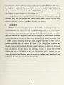
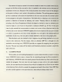
3DSHIPS
A.
3DShips
is
a
program developed by Daniel Nagel
allow users to interactively create
armament,
hulls, superstructures,
new
at the
and masts [Nage891. The complexity of the ships
window which shows them top and side views of the
and z coordinates with respect
next part will be placed or the
some icons used
(Figures 2.
1
and
to obtain
it.
built is
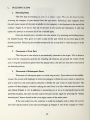
3DShips presents users with
ship being built, a coordinates
to the ship being built
last part is currently located,
menus of
to
icons for ships from different types of parts:
determined by the sum of the parts used to construct
listing the x, y,
Naval Postgraduate School
a short
a
window
where the center of the
list
of instructions, and
available options or to perform special operations
2.2).
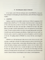
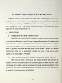
Selecting the icon for a particular part type such as hulls, presents the user with a pop-
up menu containing the parts available
must
first select it
from
however, the user doesn't
Once
dials for
this
to the user.
To see what each part
popup menu. 3DShips contains no preview
like the part selected,
the user has selected the part, he can
he can delete
move
it
changing the direction with respect to the
responsibility to determine
looks like the user
when
the part
built in capability to assist the user in
is
capability.
If,
it.
around using a dial box which has
x, y,
and z axes.
It
is
the user's
properly attached to the ship. 3DShips has no
determining proper attachment.
T
TW H|M
*.
Ik*
MM
(•**«• ln'<»«
t4l*r tar lainlt
IM>
olt «u»l>»
>Imm|
ad*«M> <k«*<»J» •Millml «»• «»«
«it*»at» »i»» tk* tn»«i- m4 >t> i««» .«.
'
«*"«
i
semi i»> >r
ffif ll i7
i
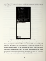
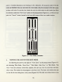
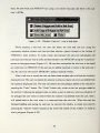
Figure 2.1
In this
The
The
3.
E
i
ma
BBM ww w*»
sr,
-
l
ll ..
l
l
3DShips' Display
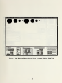
window, pick an Icon option and select with the right mouse button.
mouse button in the main display window controls additional menu items
slider bar controls the viewing distance with the cutsot and the left mouse.
When Picking, place the cutsot on the center of the desired object to delete and
1
2.
4.
-
l i l ii
right
use the middle
mouse
to select
I
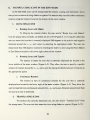
ARMAMENT
HULL TYPES SUPERSTRUCTURES MAST TYPES
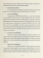
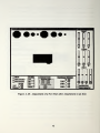
Figure 2.2
•
CONTROL
3DShips' Main Instruction and Icon
SCALE OBJ UP SCALE OBJ DOWN
Window
The user can
scale parts up and
down by
clicking the right
mouse button when
mouse button
located within one of the icon boxes for scaling. Each click of the
down and
scale factor of 0.9 for scaling
He can
because
moves on
also rotate a part 180 degrees at a time. Rotation of 180 degrees
add the next
to
than to delete
Newly
They
is
built ships are
Ship2.new,
etc.
call
numbered
to the
at
it.
be a single
part, other
ship saved
He
list
is
name given
Ship 1. new, the
to his ship, but
under the icon Select Ships. The user
can also add additional parts to
built ships.
The
it.
entire ship
is
He
cannot,
considered
unit.
3DShip's user interface
in
first
ability to select the
pop-up menu
each one up and look
The
files.
however, remove individual parts from previously
to
the user
saved by clicking the right mouse button over the Save icon.
The user has no
once saved ships are added
can then
Once
it.
are saved in sequentially
second
was selected
he cannot go back and adjust a previously placed
part,
applies a
1.1 for scaling up.
objects on a ship typically face the front or back of the ship.
all
it is
is
simple.
It
provides
some good
ideas on capabilities needed
an icon-building system.
B.
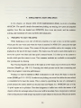
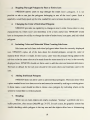
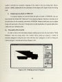
PREVIEW
Preview
[Muns891.
is
It is
built using the
a tool created by Steven
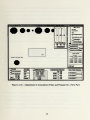
OFF file format (Figure 2.3).
Ship program, the user
model
is
at the
Naval Postgraduate School
designed to help users manipulate/modify previously created
models and save the changes
3D
Munson
is
It
3D models
allows users to scale, translate, and rotate the
to a file with the original
name
suffixed by ".new".
unable to select the name of the
file
into
which
As
in the
his revised
saved. Preview also allows users to adjust the resolution level of the displayed
polygon.
Prior to loading a
maximum
x, y,
model Preview determines
and z coordinates and
sorts all
the model's origin and the
minimum and
polygons from largest to smallest. Preview
uses this information to determine the appropriate coordinate system scale for the display
window. This helps ensure the system
This information
is
will be able to properly display
-
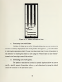
Rotating a Model in Preview
Preview allows the user to view the model as
it
would normally be displayed or
"see-thru" wire frame where only the outline of each polygon
is
sizes.
also used to adjust the resolution level of the model.
Figure 2.3
version
models of all
very helpful
when
the polygon the user wants
is in
is
as a
drawn. The wire frame
back of another polygon.
Preview has separate viewing and edit modes. In the viewing mode, the user can rotate
and
translate the
model using
sliders.
of the model. The actual model
itself
change the mddel, he must switch
and
translation, the edit
rotation, translation,
mode
These changes, however, only
remains unchanged.
to the edit
mode and
If the
affect the user's
view
user wants to actually
start over. In addition to rotation
also allows the user to scale the models. All changes to the
and scaling of the object, however, must be done by providing
the
precise angles, units of
sliders as
movement, or
scale factor.
The
user cannot
work
interactively with
he does in the viewing mode.
Preview also allows the user to cycle through the individual polygons within the model
and
to reverse their
normal vectors. Users are allowed
by selecting which polygons
to display.
Lower
to adjust the resolution
resolution
is
viewed from a distance. Since Preview has already sorted
smallest,
it is
of their object
generally desired for models
all
polygons from largest to
easy for users to identify the small polygons which can not be seen
levels of resolution.
The elimination of unneeded polygons can help improve
a graphics system, particularly
Normal vectors
if there are
many models
to
at
the speed of
be displayed.
are used to determine the front and back sides of polygons.
normal vectors are computed automatically,
it
is
lower
When
often difficult for the program to select the
proper direction for the normal vector and hence the back side, instead of the front side, of
the
polygon
may
be displayed. Preview gives the user an easy way
While Preview does not allow
it
does allow users
the user to
to delete individual
managing already created off files.
It is
to correct this
problem.
add or subtract entire parts from an off
file,
polygons and provides some important help
also a fairly simple
program
to use.
in
OVERVIEW OF NPSICON AND ITS USE
IH.
INITIAL
A.
GOALS
NPSICON
simulator,
designed to create and maintain the icons needed by NPS's
NPSNET. NPSNET
support OFF.
OFF
is
To
uses icons stored in
NPSICON
ensure
OFF changes,
remains a viable tool as
routines so that any improvements to
NPSICON or will,
OFF; hence, NPSICON
at least, require a
OFF
will
it
battle
also needs to
uses standard
automatically be included in
minimum amount of changes
to incorporate
them
into
NPSICON.
NPSICON
in the
is
also designed to
development of the programs Preview and 3DShips.
of loading and storing
into
file
improve on the work previously done
preview
at
files
a time. This
containing the icon.
exit the
".new".
If
which
is
icons
method
needs improvement. Currently, a user can only load one icon
is
done by entering the command preview and the name of the
this process.
is
Any changes made
given the original icon's
more than one change
Preview, another ".new"
NPS on
In particular, Preview's
To enter the program to view and or edit another icon,
program and repeat
are stored into a file
at
added
is
made
to the
and confusing names when the user
to the icon
file
to the icon while in
name appended by
must
Preview
the suffix
and saved during a session with
name for each change made. This
finally exits
the user
Preview and
starts to
leads to very long
use these modified
versions of his icon. This problem can be eliminated by allowing the user to choose
meaningful names for his icons.
NPSICON is designed to allow the user to load in and work
on as many icons as desired during a single session and
name
for
to allow the user to
choose his
own
any modified versions of his icons.
Preview also allows users
to
manipulate icons with sliders when in the view
by typing in the exact change needed
in the edit
8
mode and
mode. There are times when users want
to
edit their icons
and know the exact amount of the change needed. There are other times,
however, when they would
like to
change. Sliders allow users to do
more support
in
this.
One
of
NPSICON's
goals
is to
provide users with
manipulating icons when editing them.
3DShips also provides ideas
customize ships from the pieces
attached to the ship.
B.
manipulate the icon interactively to get the desired
NPSICON
is
for
NPSICON's development. 3DShips
in the system. Pieces cannot,
designed to correct
this
allows users to
however, be seen
until
problem.
OVERVIEW
NPSICON is meant to be a general purpose tool for editing and viewing existing icons
and creating
totally
new icons.
It
has both viewing and editing modes. In the viewing mode,
users can rotate, scale and translate an icon using sliders. In the edit
scale,
and translate and icon using
sliders
and by typing
in the exact
desired. Basic parts are included for bodies, cabs, tires, doors,
to
modify existing icons or
to build
new
mode, users can
rotate,
amount of change
and windows and can be used
icons. Support is provided to allow users to
examine individual polygons, reverse the normal of any polygon, and
to delete
any
polygon. Users are provided with a directory view to load icons, so an icon can be loaded
from any directory provided the user has permission
to enter the desired directory. In
addition, the user can finish
working with one icon and then load
choose the directory and
name when saving new
file
be found in the user's manual located in the appendix.
in others.
or modified icons.
More
Users can
details
can
TECHNIQUES USED IN NPSICON
IV.
In this chapter,
some of
These techniques include
the basic techniques used to build
lighting, the object file format,
and the
NPSICON
NPS
are discussed.
Panel Designer and
ToolBox.
LIGHTING
A.
Lighting
is
important in any graphics system because
displayed objects [Hall89: pp. 9-11].
We
absorbed into the object, and some
depends on the
light's intensity
affects the appearance of all
use light to determine an object's shape and color
as well as other details about an object. In the real world,
light is
it
when
light strikes
an object, some
light is reflected off the object.
and placement
as well as the material
How much
from which
the object
is
made. To obtain a realistic rendition of an object, the proper lighting model must be used.
It
should closely match the absorption and reflection of light found
real-time system,
in real time.
The
it
cannot be so complex that
lighting
model
for
it
in the real
world. In a
prevents the graphics system from running
NPSICON was
chosen with these same thoughts
in
mind.
NPSICON
edit
uses white light because
mode, a single
which the user
is
light is centered
it
allows the true color of icons to be seen. In the
on the origin and placed
viewing the object. Ambient
light (reflected direct light) is set at
enhance the display of polygons used as windshields
the user's
view
the front, top,
point,
and both sides of the
ambience of the
intensity.
and not the icon,
lights placed
Gouraud shading
is
is
in vehicles. In the
moved, four
icon.
at infinity in the direction
To
on the top and side
view mode
lights are used.
They
40%
in
cut to
20%
which
and the color reduced
lit
the
to half
used throughout to give surfaces a smooth appearance.
10
to
are placed to
prevent the icon from being over
is
from
OBJECT FILE FORMAT
B.
(OFF)
NPSICON is designed to create and work on icons stored in Object File Format (OFF).
OFF
is
Zyda
Professor Michael
at the
Naval Postgraduate School [Zyda90].
The OFF system is based on
properties of
3D
the use of operation codes (opcodes).
system, as in most
There
is
Opcodes define
the
icons such as the polygons and lines in them, the materials from which
they are constructed, and the lighting used to light them.
etc.
Munson and
a system to store three dimensional objects developed by Steven
format systems, for
file
3D
Opcodes do not
OFF
primitives such as cubes, spheres, cylinders,
one opcode for each property or characteristic an icon
render a red cube in OFF, one would need,
exist in the
at a
minimum,
six
has. So, for
example, to
polygon opcodes and one red
material opcode.
All of the opcodes pertaining to an
that the files
which allow users
full
are stored in
ASCII
to display
OFF
system also includes a
and manipulate
OFF objects. A
set
use of these pre-existing routines. This will allow
NPSICON
NPSICON
OFF
is to
to easily take
system.
THE NPS PANEL DESIGNER AND TOOLBOX
NPSICON 's
entire user interface
ToolBox (NPSPD), a
tool
was developed using
the
NPS
creation of
windows known
communicate with
Panel Designer and
developed by David King and Richard Prevatt to allow users
quickly generate graphical interfaces for their programs [King 90].
to
This ensures
of standard routines
key goal of
advantage of any improvements made to or capabilities added to the
C.
files.
can be read and edited by a user using any ASCII text editor.
In addition to the file format, the
make
OFF object
his
as panels to
program's
controls which are operated by a mouse.
NPSPD is
to
based on the
which the programmer adds the actuators needed
user.
Actuators consist of various pre -designed
Some of the actuators available
buttons, sliders, dials, directory views, boxes,
titles,
typeins,
in
NPSPD include
and typeouts. Users can
customize the actuators chosen by resizing them, changing their colors, adding descriptive
labels,
and setting
initial,
minimum, and maximum
11
values.
At any time
panels to an
in the construction process, the user
ASCII
file
called the intermediate file which contains
panels and their actuators. This
for further modifications.
Once
The
generates three
all
files:
we
all
file to
NPSPD 's Code
will use
make any
all
information on the
can be used to reload the saved panel(s) into
the user has finished completing the panels
the user (for an example,
how
file
user can also edit this
generates source code through
contains
can save any individual panel or
NPSPD
desired changes.
needed for
his
program, he then
Manager. Using the
file
name
"User_Panel" as the
file
selected by
name), the Code Manager
User_Panel.c, User_Panel_fn.c, and User_Panel.h. User_Panel.c
the information about the panels
and actuators the user has created, including
they are initialized, displayed and controlled. User_Panel_fn.c contains the functions
the user writes to react to the input received
user's
application
User_Panel_fn.c
User_Panel.h
definitions
is
program.
Immediately
from
after
the various actuators.
generation
contains the
by the Code
Manager,
basically a skeleton of functions to be filled in later by the user.
the header file for User_Panel.c and User_Panel_fn.c.
is
It
and defines the
maximum number of panels and
The source code generated by
Code Manager
the
It
contains global
actuators used.
sets
up a system which will
automatically handle the overhead associated with the panels and actuators and then feed
the desired information
from the actuators
to the user's application.
Users can either poll
the actuators each time through the display loop to detect any changes to actuators or the
panel overhead
actuator
is
management system can be
told to call a certain user function if a certain
activated or changed. Both methods
method used
is
made based on
NPSICON uses
successfully.
The decision
as to the
the user's application.
both methods with
polled each time through
work
NPSICON 's
its
actuators.
The directory view and
display function to see
if
all sliders
are
any change has occurred.
All other actuators (typeins, typeouts, buttons, and listviews) are controlled by having the
panel
management overhead system
one of these actuators changes. The
call
NPS
an appropriate function in
NPSICON whenever
Panel Designer and ToolBox provides
with an easy to use and professional looking interface.
12
NPSICON
In this chapter,
lighting, the
OFF
we have covered
the techniques behind
NPSICON's development:
system, and the interface generation system used,
and TooLBox. All of them play a key role
discuss the actual implementation of
in
shaping
NPSICON.
13
NPSICON.
NPS
its
Panel Designer
In the next section,
we
V.
In this chapter,
NPSICON. The
together,
scaling,
how
some of
discuss
VS.
NPSICON, how
loaded into
and translation of icons and
When
the implementation details involved in building
specific details discussed are picking, ray tracing,
files are
PICKING
A.
we
IMPLEMENTATION SPECIFICS
icons are saved, and the rotation,
RAY TRACING
building an icon, one of the key concerns of a user
of part desired from a menu. This causes
all
it
attached. In
the cursor over
them and then push a mouse
decide which part the cursor
is
over.
how
NPSICON,
to tell the
system
users pick the type
Two common
way
for users to pick these parts
button.
to
then up to the system to
It is
methods
is
are available to accomplish
picking and ray tracing.
Ray Tracing
requires decisions to be
made
affect the
as to
how many
rays to shoot and in which
whole picture can be time consuming and
direction [Hanr89: pp. 108-111]. Scanning the
program's real time performance.
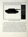
Picking
is
a built-in
method on IRIS workstations
to tell
which 3D object
cursor [Sili90: pp. 12-1—12-12]. In order to use picking, one must
is
is
the parts available within this category to be
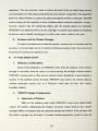
displayed at the top of the main window. The easiest
this:
are attached
their individual parts.
which part the user wants and where he wants
move
how pans
considered to be near the cursor. This
pixels around the cursor,
16 pixel square as
its
known
picksize.
is
first
done by specifying the
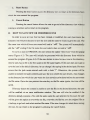
as the pick size (see Figure 5.1).
One
near the
define the area which
size of a rectangle in
NPSICON
uses a 16 by
then designates a buffer into which the names of
objects within this rectangle around the cursor will be recorded. Next, the picture
after turning
is
on pick mode and giving names
to
each object
14
is
all
redrawn
in the picture. The picture
drawn
while pick
mode
is
on
is
not displayed on the screen.
determining the objects near the cursor.
around the cursor are recorded
parts displayed at the top of the
In Figure 5.1, Object 2
to his icon
new
part.
window and
NPSICON
is
only used for the purpose of
objects which
NPSICON,
in the pick buffer. In
would be recorded
recorded in the pick buffer,
add
Any named
It is
fall
the
within the rectangle
named
objects are the
the polygons of the icon currently being built.
in the pick buffer as a hit.
By
reading the
hits
able to determine the next part the user wants to
and also the place on the icon being
built at
which he wants
to attach the
ATTACHING PARTS
B.
To
attach
two
parts together,
NPSICON
both parts and then rotate and translate the
icon.
To
needs to identify the points of attachment on
new
part so that
simplify things, the point of attachment on the
of the back of the
part.
When
it is
properly attached to the
new part is assumed to be
the user finishes initially placing a part
the center
and releases the
middle-mouse button, the coordinates of the cursor provide the x and y coordinates of the
place the
this
new
new
part
part is to be attached.
is to
be attached.
for the plane containing the
It
Using picking,
NPSICON
finds the polygon to
which
then plugs in these x and y coordinates into the equation
polygon
to
which
the
z coordinate.
15
pan
is to
be attached to
come up
with the
The amount of rotation needed is
the
polygon on the front of the new part so
that
attachment on the icon. Because of the
at this
point
is
always a unit vector
amount needed
it is
polygon
positive z direction to
become an
make
it
the
at the point
The picking process used
in the positive z direction.
on
the icon also provides the
down
of
to
normal vector
to rotating a unit vector in the
Timothy Meier
arbitrary unit vector.
method
texturing at the Naval Postgraduate School developed a
vector to
normal vector
parallel to the
of attachment This boils
at this point
normal vector for
placement the normal vector of the polygon
initial
get the z coordinate at the point of attachment
for the
to rotate the
in his thesis
on
to rotate an arbitrary unit
At
a unit vector in the positive z direction [Mei87: pp. 30-36].
the
same
time, he also created the inverse matrix to rotate a unit vector in the z direction back to the
arbitrary unit vector selected.
it
so that
it is
NPSICON applies this inverse matrix to the new pan to rotate
parallel to the icon.
attachment. In this way, the
The drawback with
new
this
It
part
method
then translates this
is
the icon.
The user must make
is that it
NPSICON
all
part to the desired point of
cleanly attached to the icon at the proper point.
vector in the z-direction. For this reason,
attached to an existing icon,
new
requires the part being attached to be a unit
when an
arbitrary
OFF
file is
brought in to be
provides no support for snapping the
the rotation
and translation decisions needed
new
part to
to attach the
part to the icon.
C.
LOADING FILES
To
icons.
be useful, an icon building/manipulation system needs the ability to load in existing
NPSICON
each directory.
allows users to locate
by searching through the
files
contained
NPSICON starts this search process from the directory from which
entered the program.
session, he can start
to the directory
files
The next time
the user requests to load a file in the
from the directory from which he loaded
same
directory, these default settings
16
the user
same program
the last file or he can return
from which he entered the program and search from
are often stored together in the
in
there. Since
make
OFF files
sense.
STORING FILES
D.
When
want
storing files, users need to specify both the path and the
their icon stored.
Because users usually store
from which users enter the program
is
name where
they
files in a single directory, the directory
loaded as the default path name. This means that to
save icons, most users will only have to enter the
E.
file
file
name.
ROTATION
In the edit
the axis around
mode,
rotation
is
which the rotation
accomplished by determining the amount of rotation and
is
desired and then passing these parameters into the
function "rotate_this_object." In view
mode
the
same thing
is
OFF
done, but the parameters are
passed into the IRIS graphics library function "rotate" which rotates the viewing matrix
instead of the icon.
F.
SCALING
In the edit
the
mode, scaling via input from
amount of scaling desired in
into the
OFF
the x, y,
the typeins
function "scale_this_object." Scaling via input from the sliders
moved down. This
the object
accomplished by determining
and z directions and then passing these parameters
inputting a scale factor of 1.01 each time the slider
slider is
is
is
moved up and
is
done by
0.99 each time the
allows the user to see smooth scaling as he interactively scales
up or down. In view mode again the amount of scaling and the direction
is
determined, but the parameters are passed into the IRIS graphics library function "scale"
which scales the viewing matrix instead of the
G.
icon.
TRANSLATION
In the edit
mode,
translation is
accomplished by determining the amount of translation
desired in the x, y, and z directions and then passing these parameters into the
"translate_this_object." In
view mode the same thing
into the IRIS graphics library function "translate"
instead of the icon.
17
is
OFF function
done, but the parameters are passed
which
translates the
viewing matrix,
NPSICON LIMITATIONS AND FUTURE DIRECTIONS
VI.
NPSCION
It
provides another step forward in the ability to build and manipulate icons.
expands the previous work done
greater flexibility in dealing with
when dealing with
in the
development of Preview and 3DShips.
OFF files,
but
still is
This chapter discusses
icons.
short of solving
NPSICON's
all
It
provides
of a user's needs
limitations and
some
suggestions for future enhancements to it
A.
LIMITATIONS
1.
Orientation of Parts to be
NPSICON only
Added
to
has the ability to automatically attach a part with a normal vector
in the positive z direction to
an icon.The user
rotation decisions to attach a
pan which does
this restriction
an Icon
and gain the
is
responsible for making
any pan
needs an algorithm to rotate an arbitrary normal vector to make
together can be easily added to
2.
any time.
to
it
an icon,
and
To remove
NPSICON
parallel to a desired
available, the ability to snap
any two parts
NPSICON.
Ability to Rotate, Scale,
Users need the
is
translation
not contain such a normal vector.
ability to automatically attach
normal vector. Once such an algorithm
all
and Translate Any Part
ability to rotate, scale,
and
in
an Icon
at
Any Time
translate all of the parts in an icon at
NPSICON only allows users to do this when a part is first added to an icon. Once
a subsequent part
starting over.
is
added, a user can only adjust a previously added pan by deleting
it
and
This overly complicates the process of adjusting an icon's parts and needs to
be remedied in any future version of
NPSICON.
18
3.
Stepping Through Polygons by Part or Entire Icon
NPSICON
allows users to step through the entire icon's polygons.
is
It
not
possible to ask to see just the polygons belonging to one of the icon's pans. Such a
capability
4.
would help speed up
the time needed for users to locate desired polygons.
Changing the Color of Individual Polygons
NPSICON
characteristic
provides no capability to change an icon's color. Since color
by which icon's are
have to incorporate the
ability to
be a truly useful
identified, to
tool,
change the color of entire icons, icon
is
a key
NPSICON would
and individual
parts,
polygons.
5.
Including Color and Materials
When
Creating Sub-Icons
Sub-icons are built from individual polygons taken from the currently displayed
NPSICON
icon.
copies
material from which
all
it is
of the data about the desired polygon, except the color or
made. In most cases, users want the polygon being added
sub-icon to be the same color or to be
displayed icon.
The
NPSICON
made from
the
same material
as
it
was
to the
in the currently
should not force users to add the color and material definitions.
built-in default for the sub-icon
should be the same colors and materials used in the
icon.
6.
Adding Individual Polygons
NPSICON does not allow users to add individual polygons.
There are times when
a piece needed for an icon does not exist and cannot be created by scaling an existing piece.
In these cases, a user should be able to create a
screen he would like
7.
its
new polygon by
indicating where
on
the
vertices placed.
Decaling
When two
or
more
objects are nearly co-planar, "tearing," a problem due to z-
buffer precision, often occurs [Akel90: pp. 31-37]. In such a case, the graphics system has
trouble deciding
which polygon
is
the top
one and the objects often have a shimmering
19
appearance. The user, however, wants to achieve the result of the top object being decaled
over the bottom one. This result can be achieved with a Painter's Algorithm. This algorithm
draws the objects
and adds some special z-buffer commands. The
farthest to nearest
system already has the capability
to
draw co-planar objects using
NPSICON
is
not presendy able to do
the section used to identify the
8.
polygon
to
although
it
it,
identified.
could be easily added by modifying
which a user wants
to attach a
new
part.
Problems with the Window Manager
If
boundary
is
window boundaries
are crossed too quickly, actuators
do not function
until the
recrossed again slowly. In addition to being annoying to users, this slows
the process of creating
B.
this,
Using
this algorithm.
however, requires that the underlying objects and the decaled objects be
OFF
down
and updating icons.
FUTURE DIRECTIONS
1.
Efficiency Considerations
Much
manager
of the inefficiency of
NPSICON
to accurately track the cursor as
NPSICON,
it
stems from the inability of the
moves among
causing users to often have to recross
function. If the
problem cannot be
fixed,
interface generation system such as
the multiple
window boundaries
NPSICON may
X Windows
need
window
windows used
in
to get actuators to
to be written using
which does not have
this
an
window
boundary problem.
2.
NPSICON
a.
Design Considerations
Appearance of Windows
Many
of the windows used within
NPSICON would
have looked better
without the borders. Eliminating the borders, however, totally destroys the
managers
the
ability to recognize that the cursor has entered that
window manager can be
fixed or
if
window.
If the
problem with
another interface generation system
20
window
is
used, the
appearance of
tides
NPSICON
on many of
will be greatly
enhanced by the elimination of the borders and
windows.
its
Color and Material
b.
NPSICON
needs to provide users with the ability to choose the materials and
colors used to render icons and sub-icons.
The
user should be able to use both existing
colors and materials and to interactively create totally
c.
new
colors and materials.
Attaching Parts
To be
parts together.
The
a useful system,
NPSICON
has to provide the ability to snap arbitrary
current restrictions on this procedure discussed above in
Pan A. 1
are
unacceptable.
3.
Portability Considerations
NPSICON
The
to
is
ideas presented on
designed to run on IRIS workstations and to manipulate
how
OFF icons.
icons can be created and manipulated, however, are applicable
any graphics hardware and
file
storage system.
21
vn. CONCLUSIONS
The development of NPSICON has provided some
functions needed in a system to create and manipulate
3D
insight into the capabilities and
icons. First of
there are three
all,
levels to be addressed: the icon as a single indivisible object, the icon as a collection of
and the icon as a
parts,
set
of individual polygons. Each level has
its
own
set
of individual
needs.
When dealing
with an icon as a complete object, users need the ability to rotate, scale,
and translate the icon by both exact amounts and interactively using
to
sliders.
They
also need
be able to perform rotations, scalings, and translations on the viewing matrix, instead of
the icon.
NPSICON
When
parts
and
provides
all
of these functions.
dealing with an icon as a collection of parts, users need the ability to add
and resize old
to adjust
parts.
NPSICON
allows users to add
system and also new parts supplied by the user from
cleanly snap one of
The user
is left to
Clearly, this
its
system parts
make
to
it
files.
While
parts
and translations
make
to
NPSICON allows users to scale, rotate,
the part they are currendy adding to an icon.
does not allow them to go back and adjust
Once
it,
it.
This
is
to
this
can
an icon.
happen.
and translate
the part is added, however,
other than to delete
from the
NPSICON
cannot snap a user supplied part
the necessary rotations
an area for future work.
is
an icon,
OFF
new
new
NPSICON
also an area
which needs further work.
When
dealing with an icon as a set of individual polygons, the user needs the ability
to view, add,
polygons.
and delete polygons, as well as the
ability to reverse the
normal vectors of
NPSICON allows the user to view and delete polygons, as well as reversing their
normal vectors.
It
also allows users to select polygons
22
from an icon and copy them
into a
sub-icon.
NPSICON
the vertices.
It
does not, however, allow users to create new polygons by specifying
also has
NPSICON shows
no capability
that icons
to specify the color or material
can be easily created and manipulated interactively.
provides another step toward a complete system to manage the
Naval Postgraduate School's
of individual polygons.
battle simulator,
NPSNET.
23
OFF
It
icons used within the
APPENDIX
NPSICON USER'S MANUAL
OVERVIEW
A.
NPSICON is a program to allow users to view, manipulate, build, and modify 3D icons
or objects stored in the Object File Format (OFF). Unless the user specifically selects the
view mode, everything
scalings,
in
and translations
scalings, or translations
the
is
model looks
NPSICON is done in
alter the actual
done
B.
mode. This means
to the user. In all but the
is
that all rotations,
model. In the view mode, however, any rotations,
have no effect on the icon
will
designed to be a "what you see
the edit
itself.
They only
view mode the icon changes because
affect
how
NPSICON
what you get" system.
HOW TO USE NPSICON
NPSICON
can be run from any directory by ensuring the user's login shell contains a
path to the directory containing
which the program
Hence, searches for
is
NPSICON and by then typing npsicon. The directory from
entered becomes the default directory for storing and loading
files will start
from
this directory,
files.
and any objects stored by the user
will be placed in this directory, unless the user specifies otherwise.
C.
INTERACTION WITH NPSICON
Users interact with
1.
NPSICON via the mouse
and keyboard.
Mouse
The mouse, an input device with
input device to
NPSICON.
Its
three buttons
which
buttons are designated from
middle-mouse, and right-mouse.
24
slides
on a pad,
left to right
is
the key
as left-mouse,
a.
Left-
mouse
The left-mouse
menus, buttons, typeins, and
b.
is
used to control
sliders
and are discussed
is
used
down
the icon being built. Pressing
in Section
to select
and
c.
pans
to be
its
added
when
to
the
to the desired position.
attach
pan mode.
Right-mouse
The right-mouse
is
used to allow users to make selections from
main function menu (Figure A.l). Depressing
to appear.
move through
By moving
the
menu
appropriate selection
is
the
to
mouse while
make
the right
still
it
to
mouse button causes
this
popup
depressing the right-mouse, the user can
his selection.
highlighted causes
NPSICON's
Releasing the right-mouse when the
be selected.
Keyboard
The keyboard
is
used by
NPSICON to allow the
rotation, scaling, or translation desired.
in section
D.
static
of the Appendix.
without releasing the middle mouse button
over the desired part allows the user to drag the part
is
2.
D
initially position
Releasing the middle-mouse causes the system to go into
menu
These actuators include
Middle -mouse
The middle-mouse
cursor
actuators.
all
user to enter specific amounts of
These amounts are entered
into typeins (discussed
D of the Appendix).
HOW TO USE NPSICON'S ACTUATORS
NPSICON
utilizes a variety
of actuators. These include
static
menus, buttons,
sliders,
and typeins. Details concerning the implementation of these actuators can be found
[King90].
25
in
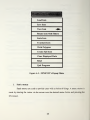
Load Icon
Save Icon
View Icon
Rotate Icon with Sliders
Scale Icon
Translate Icon
Walk Polygons
Create Sub-Icon
Clear Displayed Parts
Reset
Quit Program
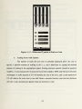
Figure A.l
1.
Static
menus
Static
menus
made by moving
-
NPSICON's Popup Menu
arc used to provide users with a choice of things.
the cursor via the
mouse over
left-mouse.
26
the desired
A menu
menu choice and
choice
is
pressing the
2.
Buttons
Buttons are either square or round and are used
or off.
They
moving
are controlled by
in
the cursor via the
NPSICON
mouse onto
to turn
an option on
the button
and then
pressing the left-mouse signaling selection of the button.
3.
Sliders
Sliders allow users to obtain continuous values
minimum
value. Sliders are controlled
all slider
movement. Finer control
can be obtained by holding
down
the left-
moving
(i.e.,
the
the exception of the slider to
which
4.
resets all sliders in that
and right-mouse buttons simultaneously or by
walk the icon's polygons,
window
have a
the slider.
reset button
to their initial positions.
Typeins
as a blue box.
To
cursor so that
it is
activate
it
An
and hence signal the user's desire
in the typein.
Then press
to turn pink, signaling the typein is
inactive typein appears
to provide input,
move
the left-mouse. This will cause the typein
the
box
ready to accept input. The user can then enter his input
from the keyboard. The backspace key can be used
E.
when moving
all sliders
Typeins are used to accept input from the keyboard.
When
mouse. Releasing the
slower movement) of the slider
pressing the control key and the left-mouse button at the same time
With
maximum and
by moving the cursor via the mouse onto the blue
bar in the slider and then depressing the left-mouse and
left-mouse stops
between a specified
to
remove any mistyped
characters.
the desired input has been entered, the user presses the return key.
NPSICON's WINDOWS
NPSICON
is
a window-based program. Hence, the program communicates with the
user by opening up different
actuator does not respond,
that the cursor is in the
user should
move
windows which
it is
window
often contain actuators.
If,
for any reason, an
probably because the window manager does not recognize
containing the desired actuator.
the cursor outside the
window
27
To
solve this problem, the
containing the desired actuator and then
slowly
the
move
window
the cursor back into the
window's boundary,
As
containing the actuator.
the cursor crosses
the user should see a red circle with a dot in the middle appear
momentarily. This signals that the window manager recognizes the cursor's change in
windows. The actuators
F.
in this
window should now
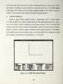
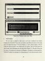
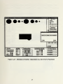
INITIAL DISPLAY
Initially a single
A. 2). The top half of
axes. This top half
contains
some
window
this
is
entitled "npsicon
window
build/modify icons"
used to display any icons being viewed or
basic control actuators: the part
minimum and maximum bounds
the cumulative rotation
done
to
it
a—
OO
MmmQQ
menu, typeins
some
in the x, y,
around the
^^^^ ^^^TS!^T?!SSSBB
58£3
-
is
built.
to control
special purpose buttons.
and
x-, y-,
*
—
••*•
»M*V
^fz
r*
i
_-.
-
also displays
and z-axes.
"i
naicii
3EE E 9 i—
NPSICON's Main Window
28
!
*m
i
g>
f
.
'.
mv L
/
half
rotation,
z directions for the displayed icon
vjgHSBSKiC
I
It
'2553^^5^5S3
'
aas-
-
The bottom
one time
WMMmMBmiMI
Figure A.2
visible (Figure
blank except for lines indicating the positive x- and y-
is
buttons to control continuous rotation, and
the
function properly.
and
Part
1.
The
The menu
Menu
part
menu
used to select parts
is
itself lists the categories
Windows. Selecting
desires to view his icon
is
over the
at the
and z-axes. Continuous rotation
from
all
is
on and off continuous
very useful
when
the user
angles.
One-Time Rotation Typeins
3.
The one-time
rotation
from
amount of
amount of
rotation typeins allow the user to input the desired
the keyboard. This is useful
when
the user wants to rotate an icon an exact
rotation around a specific axis.
Flip 180 Degrees Button
4.
The
"flip
180 degrees" button allows any
rotated 180 degrees. Often
when
will be rotated an extra
the part is attached with the
function
is
parts are
added
part, other than the first one, to
to the
back side of a vehicle the part being
180 degrees. In the case of wheels with hubcaps,
hubcap pointing
in
be
this
means
toward the vehicle instead of away. This
useful to correct this problem.
Delete Attached Part Button
The
"delete attached part" button brings up a
parts in the currently displayed icon [Figure A.3].
editing session will be listed. If the current icon
will be considered to
still
the cursor
of the parts available in that category to be displayed
rotation buttons allow the user to turn
rotation around the x-, y-,
it
when
window.
The continuous
5.
of parts available: Bodies, Cabs, Tires, Doors, and
Continuous Rotation Buttons
2.
added
all
dimensional icon.
to build a three
a part category by pressing the left-mouse
desired part category causes
top of the
be used
to
window which
Only
parts
was brought
added
in as a
lists all
the separate
to the icon in this
complete off
file,
then
be a single part for deletion purposes. In such a case, the user can
delete individual polygons by selecting
"Walk Polygons" from NPS ICON'S popup
29
menu
(Figure A.
1).
Details on the deletion of individual polygons can be found in
Pan
M
of the Appendix.
Figure A.3
To
select
-
Window Used
one of the
to Delete Parts
listed parts, the user places the cursor
desired part and presses the left-mouse. This causes the
in
dark blue.
He can
also use
From an
one of the
name of the
Icon
over the name of the
part to be highlighted
scroll buttons to highlight the
name of the
wishes to consider for deletion. The user then presses the "Display" Button
part he
to see the
pan
highlighted in white and oudined in red or the "Delete" Button to delete the pan. After a
pan is deleted,
it
can be restored by pressing the "Delete Last Part" button. The "Delete Last
Part" button only works for the last part which
30
was
deleted.
Once
the user
moves on
to
delete another part, any previous deletions cannot be undone. Similarly, undoing the last
deletion does not allow a user to
undo any previous
Delete Selected Part Button
6.
The
attached
it
"delete selected part" button allows a user
to the icon
Axis
7.
On and
user
is
users,
NPSICON draws the positive x-,
submenu appears and
-
will
it.
menu
and z-axes
-
Mode - Top
its
in red, green,
and y- axes are
(Figure A.l) to the right of the entry
selecting one of
Side View," and "Edit
y-,
depend on the user's view
presented with a front view and only the x
following the arrow on the popup
until a
has selected a part but not yet
Off Buttons
and blue respectively. The axes which are visible
Initially, the
who
being built to delete the selected part prior to attaching
To help orient
Mode
deletions.
options ("Edit
Mode
View"), the user can see
-
corner of the Main
but selects Axis
8.
On
Front View," "Edit
all
These
three axes.
the axes, the user follows the
in the
lower
same procedure,
On and Off Buttons
the icon that is currently displayed as a wireframe or skeleton in
only the outline of each polygon
located in the lower
By
Button.
Wireframe
To display
Window. To redisplay
visible.
"View Icon"
axes can be removed from the screen by selecting the Axis Off Button located
left
point.
left
is
On
Button
to the
normal
drawn, the user should select the Wireframe
corner of the
Main Window
display of the icon, the user should follow the
(Figure A.4).
To return
same procedure, except
which
select the
Wireframe
Off Button.
9.
Update Icon's Bounds Button
Whenever an icon
are displayed in the
is
loaded into
box located
in the
NPSICON,
its
minimum and maximum bounds
lower center of the Main Window.
If the
icon
is
changed, however, through rotation, scaling, or translation, these displayed bounds will not
reflect the
changes
to the icon's
bounds.
To
obtain the icon's current bounds, the user
31
presses the "update icon's bounds" button located above the box displaying the icon's
bounds.
HOW TO LOAD FILES INTO NPSICON
G.
To
menu
load files into
(Figure A. 1).
NPSICON,
The
the user selects the option
"Load Icon" from
the
popup
user will initially be presented with a directory view listing the files
contained in the directory from which the user entered the program (Figure A. 5). The user
can select any
directory
file
or directory in this directory by placing the cursor on the desired
name and pressing
the left
mouse button.This
to be highlighted in dark blue. Directory
directory
from
scroll bar
and up and down arrows
of the
names within
file
1.
names
are followed by a slash "/".
the current directory select the top entry in the directory
to the left of the directory
or
name
To move up one
view
view can be used
"../".
to
The
view
all
the current directory.
Accept Button
Pressing the accept button causes
into the
will cause the file or directory
file
system or
to
change directories
if
NPSICON
a directory
32
is
to load the currently selected file
selected.
NOTE:
(1)
When
the first
icon
is
loaded, the user
is
presented with a front view. The positive x- and y- axes are
displayed and the wireframe option
the upper left
is
turned off. (2) Subsequent icons will be loaded into
hand corner of NPSICON's main window. The user can then adjust
window brought up on
icon's position and size using the sliders in the
main window
NPSCICON
for this purpose. (3)
will only load files
the user of the problem. (4) All
and
OFF
will bring
which end
in
end
".off. If
".off,
in
up an error notification window
loaded into
files
NPSICON
definitions for any materials used in them. If the material definition
is
new
the right side of the
the user presses the accept button and the file currently highlighted does not
the system will refuse to load the file
this
to tell
should contain the
not contained in the
OFF file, the user will receive the following error message "retrieve_opcode_by_name: We
did not find that
name
in the
name
table
= <material name>." NPSICON
material, white, in place of the material
••
whose
definition
was not found.
M^WBWWBW^W^H^^^
•'••'
Csuncd
.rvi'
'
.
'
.
'
' ' ' ' '
. .'. . . . . .
mmmmmmm
'T. ' . ' .' . 1 .
Figure A.5
-
Load
33
File
Window
will use
its
default
Reset Button
2.
Pressing the reset button causes the directory view to return to the directory from
which the user entered the program.
Cancel Button
3.
Pressing the cancel button allows the user to get rid of the directory view without
making
a selection
and
to return to the
program.
HOW TO SAVE NEW OR MODIFIED ICONS
H.
In order to save an icon that has
been created or modified, the user must know the
name he wants
directory into which he desires to save the icon and the
file
name
into
which
add the ".off" ending
To
menu
icons are stored will end in ".off".
all
if
save an icon in
the file
NPSICON,
The user
(Figure A.l).
name
The system
the user selects does not
the user selects the option
end
fill
name
in the file
name
save the icon in the default directory, he can change
ensure that the path
name
will automatically
in ".off".
will initially be presented with the directory
in the file
it
new
from which he
icon in this directory,
typein. If the user does not
by typing in
the desired path.
the file
want
to
He must
entered ends with a slash "/". Otherwise, the system will be
unable to interpret the path correctly and save the icon where the user desires.
to the directory into
The
"Save Icon" from the popup
entered the program (Figure A.6). If the user desires to save his
then he only has to
to give the icon.
Any changes
which the user wants the icon saved must be done before the user enters
name. Once the user presses the enter key on the
file
name
typein, the icon will be
saved.
If for
any reason the system
is
unable to save the
will be notified via an error notification
directory already contains a file with the
file in
the desired directory, the user
window. The user
same name
will also be notified if the
the user selected. In this case, the user
will be given the option to overwrite the file, overwrite the file but save the original file as
a backup, or go back
and
select another file
the icon, he can return to the
name.
If the
program by pressing
34
user changes his
the cancel button.
mind about saving
1
Directory
RleName
Cancel
i^^
!
^^ ! -^y ^?
v"^^^^ v^^^^^ T^^^^T ^^^^"^^
!
^
^
Figure A.6
I.
-
Windows Used
to
Save
Files
VIEW MODE
The view mode
is
available to allow users to
changing the actual model.
menu
view icons
in different
ways without
To enter the view mode the user follows the arrow on
to the right of the option
"View Icon"
should then select the option "View
(Figure A.
Mode" from
this
1) until
the
popup
a submenu appears. The user
submenu. The view mode allows the
user to rotate, scale, and translate an icon using sliders (Figure A.7).
The
user
is
also given
the choice of viewing the icon through an orthographic or perspective viewing projection.
NPSICON's default
is
the perspective viewing projection.
35
It
was chosen because
it
allows
users to visualize translations and scalings in the z direction. All actuators used in the edit
mode
are disabled
window
the
will work.
when
the user enters the
view mode; only the actuators
submenu under the "View Icon" option on
in the
'jBy l
the
lower
[**.*\
*^?
c
1
popup menu (Figure A. 1), or the user can
left
[**«*1
corner of the view
mode window.
l*K**j
^ W^yitef]
Figure A.7- View
Mode
Actuators
VIEWING THE ICON IN THE EDIT MODE
By
following the arrow to the right of "View Icons" on the popup
and selecting "Edit
Mode
-
Front View," "Edit
View" from
the
submenu which then appears,
side, or top.
The
default for the
to
view mode
To exit the view mode, the user can either select an edit mode view from
push the "Cancel" button located
J.
in the
view the
his icon along the x-
program
is
Mode
-
menu
Side View," or "Edit
the user can
the front view.
view
The
his icon
front
(Figure A.l)
Mode
from
Top
the front,
view allows
and y-axes (Figure A. 8). The side view allows him
36
-
the user
to
view
it
along the y- and z-axes (Figure A.9).
And
the top
view allows him
and z-axes (Figure A. 10).
+y
+x
Figure A. 8
Front View of an Icon
-
+y
W
Figure A.9
-
Side View of an Icon
+x
+z
Figure A. 10
-
Top View
37
of
An
Icon
to
view
it
along the
x-
MANIPULATING ICONS
K.
In the edit
mode
IN
THE EDIT MODE
icons can be manipulated by rotation, scaling, and translation. Users
always have a choice of using sliders or typeins. For rotation they can also select continuous
rotation using the buttons
found on the bottom of the main window.
ROTATING ICONS
1.
a.
Rotating Icons with Sliders
To
bring up the rotation sliders, the user selects "Rotate Icon with Sliders"
from the popup menu.
Initially, all sliders are set to
user can rotate the icon that
is
0.0 (Figure A.l
1).
Using the
currently displayed 360 degrees in the positive and negative
direction around the x-, y-, and z-axes by selecting the appropriate slider.
obtain
to
more than 360 degrees
Zero Button located
b.
in the
sliders the
rotation
by resetting the
The user can
sliders to zero using the Reset Sliders
lower right corner of the window.
Rotating Icons with Typeins
The typeins
to rotate the icon that is
currendy displayed are located
in the
lower middle of the main window (Figure A. 2). They allow the user to specify a specific
amount of rotation around
the x-, y-,
and z-axes by typing the desired amount of rotation
in
the appropriate typein.
c.
Continuous Rotation
The buttons
to turn
on continuous rotation for the icon
displayed are located in the lower right of the main
window
that is currently
(Figure A.2).
They allow
user to rotate his icon continuously around the x-, y-, and z-axes. Rotation around
one axis
2.
at a
is
more than
permitted.
TRANSLATING ICONS
To
the
time
the
translate the currently displayed icon, the user selects "Translate Icon"
popup menu. The user can then
from
rotate the icon using sliders or typeins (Figure A. 12).
38
Figure A. 11
-
Sliders to Rotate
Translating Icons with Sliders
a.
Initially, all sliders are set to 0.0.
icon that
an Icon
Using the
sliders the user
can translate the
currently displayed ten units in the positive and negative x, y, and z directions
is
by selecting the appropriate
slider.
one direction by resetting the
The user can obtain more than 10
sliders to zero using the
units of translation in
"Reset Sliders to Zero Button"
located in the lower right corner of the window.
b.
Translating Icons with Typeins
The
specify a specific
amount of
typeins to translate the icon that
amount of translation
is
in the x, y,
translation in the appropriate typein.
39
currently displayed allow the user to
and z directions by typing the desired
'*
i*\
Figure A.12
3.
-
Sliders
and Typeins
to Translate
an Icon
SCALING ICONS
Users can make the currently displayed icon larger or smaller by selecting "Scale
Icon" from the popup menu. The user can then scale the icon using sliders or typeins in the
x, y,
or z direction individually or in
a.
all
three directions at
Scaling Icons with Sliders
Initially, all sliders are set to 1.0.
The
the appropriate slider up, or he can scale the icon
user can scale the icon up by
down by moving
down. The user can obtain greater scaling of the icon by
the "Reset Sliders to
moving
once (Figure A. 13).
moving
the appropriate slider
resetting the sliders to zero using
Zero Button" located in the lower right corner of the window and again
the scaling sliders.
40
•saw **<am*i
-imm
•
-ay
I
*mt
•
pg [||S
fctM
pEi
CiT*k-,»-
Figure A. 13
A.
•
Sliders
and Typeins
an Icon
Scaling Icons with Typeins
The typeins
to scale the icon that is currently displayed
specify a specific
amount of
amount of scaling
in the appropriate typein. Scaling
numbers.
to Scale
allow the user to
scaling in the x, y, and z directions by typing the desired
amounts entered should be positive
A scale amount of 1.0 causes the icon to be scaled to 100% and will leave the icon
unchanged.
A
scale
amount of 2.0
will
double the size of the icon, and a scale amount of
0.5 will reduce the icons size by one half. Hence, amounts between zero and one decrease
the icon's size,
and amounts greater than one increase
41
its size.
L.
BUILDING ICONS
Selecting Parts
1.
The
first
step in building an icon
from
selecting the category of part desired
the part
menu causes
all
select a pan. This can be
the part
menu. Selecting
done by
first
pan category from
a
the parts available in that category to be displayed at the top of the
window. Figure A. 14 shows how
repeat this process to examine
Once
is to
the desired part
all
is
all
of the
tires in the
system are displayed.
A
user can
of the available parts.
located, the user selects
the middle-mouse. This gives the user a
by pressing and holding down
it
copy of the part which he can then drag
desired position. Releasing the middle-mouse
tells the
system
this is
where
the part
to the
is to
be
done
to
placed.
Placement of First Part
2.
The
first part
a user selects
is
automatically centered at the origin. This
help with the construction process by ensuring
icon.
all
is
rotations are around the center of the
Using the translation option from the popup menu, the user can
later
move
the icon to
the desired position.
3.
Placement of Subsequent Parts
Placement of subsequent parts
mouse, the system
part to
is
a multi-step process.
will highlight in white the
and show red cross
hairs at the point
polygon
it
it
Upon release of the middle-
thinks the user wants to attach his
thinks the user wants to attach the part.
system will then display a window asking the user
if this is in fact
part placed (Figure A. 15). In addition to answering yes or
no as
The
where the user wants
his
to placing the part at the
specified location, the user can also cancel the part and try again by pressing the "delete
selected part" button found in the lower right corner of the
If the
move
the red
user selects no, the
windows
to
main panel.
walk the polygons and
placement cross hairs are brought up (Figure A. 16).
42
to allow the user to
If the
polygon
to
which
aatoatfc»rt*w<iMrt
MttfaiMfiMMtftittM
<^H
^n^BflU
0| £2X22
f #Mhftl Bi MkkM
TgSSSS CbMbSii
B«^hf^Wi
utT2T|2|]nlQ|||r^
[1111111 1
KM|«t:
1
gg (JO
Figure A.14
I 1f\
-
Window
l
HilfciFlffT ttrfi^im
TitlUI
|n
Displaying All Tires Available Within
43
««
y
«i
~
ii»
:
l
NPSICON
1
am
Pe^
^^J
>
.-I.I.I..J
Cafltiat^RM ROtklJMi
"susrsKnsKS
-
:*5 %
I
Figure A. 15
-
;J "
*
Selection of Initial Attachment Point for a
44
Sfi
New
ttJHBj
Part
I
^jlSWlMJBMJ
Pl'AiteOtoCtTOtWrfii^n
'.^^^•J^ *.^^^p^^ Jf^^^^^v
imm Uww
% ftHN0t
I-
m »>
J*
.WRWV9VT 5\*^"^^^
i^ww
LJJMMtilfr
M&MM
1
JifWtT
-*^^
T-Jl^
BWMtt
LJ
Qi«s»3n
^A<< ^<>^B>
jO»Brt«uo«R<*»t»>«!
I^fe^SlL
«*L
raQO
B300
DjMB
I*
Figure A. 16
-
OscT^meRoteiian
1
£=***«=£
Adjustment of Attachment Point and Polygon for a
45
New
Part
the user wishes to attach his part is not highlighted in white, the user can user the slider or
the next
and previous polygon buttons so
hairs are not at the position at
using the
the
x, y,
and z
polygon button
user
if
is to
it
is
highlighted. If the red placement cross
which the user wants
sliders in the attach
polygon the part
that
pan
location
his part attached, he
window.
When the
can
user
is
move them
happy with
be attached to and the placement location, he presses the attach
to attach the part to the icon.
The system then puts up
a
window asking
the
he wants to adjust the placement of the part further (Figure A. 17).
user selects yes, the part
If the
is
attached to the icon and the user
he wants to adjust the placement of the part further (Figure A.
on backwards, the user can
by pressing the
fix this
flip
17). If at this
then asked
if
point the part
is
is
180 degrees button found
in the
lower right corner of the main panel.
4.
Adjustment of Part after
window is brought up to do this
and scaling
sliders
dimensional icon, he
view.
When
all
(Figure A. 1 8). This
which allow the
axes and translated in the
placed from
Attached to the Icon
user decides to continue adjusting the part once he has attached
If the
a
it is
is
x, y,
part to be rotated
is
5.
x-, y-,
and
z-
dealing with a three
to rotate the object to ensure the part appears properly
what looks
fine
from the
front, doesn't
look fine from a side
the user is satisfied with the part's placement, he signals this to the system by
pressing the "Finished Adjusting Part Button" located in the lower
window
to the icon,
rotation, translation,
and scaled around the
and z directions. Because the user
encouraged
angles. Often
window contains
it
left
corner of the
to adjust the part.
Adding Parts Not Included
Users can add any
Icon" from the popup
OFF object.
menu
OFF
(Figure A.l) and then loading the
be placed in the upper
this file is loaded,
which allow the user
Menu
object to the icon they are building by selecting
Initially this object will
main window. As
in the
NPSICON
to rotate, translate,
and scale
46
left
brings up a
file
"Load
containing the desired
hand corner of NPS ICON'S
window
this object (Figure
containing sliders
A. 18).
NPSICON
is
a
U^iy.yjj^/y.f^ff.^f^^ifSfWff-ffl
0^3
Qb
G^S
r^Tr "9EJU
C)ti«
....
"£~^^
TXn*
fcatttlan
^^ 'i^ji'yjj^"
LggdjilUBlIC
I"
:
««
QO
it;
Figure A.17
-
Decision on Further Adjustment to a
47
New
*yC
Part's Placement
mm Mm Mm
awwj:,.i
I
CmltoaiMM
I.
i
Figure A.18
-
w
iaoo
IMWt M**M
vs ws >s \ -Js s" C^
^ Css*^ syivwyiftwyw W
Adjustment of a
Kottrtian
fw^^j
ii^irfta* f*!]!^
i
New
Part after Attachment to an Icon
48
unable to provide any automatic snapping of this object to the icon being
theuser
is totally
built.
Hence,
responsible for the placement of this object with respect to the icon being
built.
6.
Displaying Icons Built in
To
NPSICON
properly display an icon built from the parts provided
must include the header
file
along with each part as the icon
M.
NPSICON,
the user
"material. h" in his display program. Material. h includes
the definitions for the materials used within
within the icon's definition
in
is
NPSICON.
all
of
Material definitions are not added
being built to avoid duplication of material definitions
file.
WALKING POLYGONS
In order to look at the individual
polygons making up an icon, the user selects "Walk
Polygons" from the popup menu. The window which comes up contains a variety of
actuators designed to help the user
work with
the icon's polygons as well as listing the
current polygon's normal and vertices (Figure A. 19).
QS68B3HHB
;
|
jiK**^MMMfs
1^-^*1
t
^1 gSSKSfiiiBBft J^Mp*-:
CmmmMwk
«
'.
***p
?»«« *****
a
$)mmh
-AAtnw
^wnw
MHIMHMMHi
Figure A. 19
-
Walking an Icon's Polygons
49
Polygon Slider
1.
The polygon
polygons.
the left
It is
slider allows the user to quickly
move
all
of the icon's
operated with the left-mouse, but finer control can be obtained by holding
and middle mouse buttons or the control key and
simultaneously.
the current
through
The polygon
polygon the user
slider displays the total
is
looking
at.
mouse button down
left
number of polygons
In addition the current
polygon
in the
is
icon and
highlighted in
white and outlined in red in the icon.
Next and Previous Polygon Buttons
2.
The next and previous polygon buttons
through the polygons
in either direction.
are used to allow the user to single step
These buttons are useful when a user desires
to
slowly step through the icon's polygons.
3.
Reverse Normal Button
The reverse normal button allows
(i.e.,
to rotate
it
180 degrees). In a graphics system, color
front side of a polygon.
side of the
the
polygon
is
normally only applied to the
is its
front
and hence which side gets the
color.
It is
normal the wrong way and hence have the polygon back facing
to fix this
4.
very easy to point
front.
This
is
easy to
The reverse normal button provides an easy way
problem.
Delete Polygon Button
Speed
speed
normal
A polygon's normal vector is used to tell the graphics system which
detect since the polygon will appear black.
in
the user to reverse the current polygon's
is to
is
key
to the success of
any real-time graphical system. One way
to obtain
avoid doing anything unnecessary, including depicting extra or unseen polygons
an icon. Often because of the way an icon will be displayed there
that will not
may
be portions of
it
be visible to the user, such as the underside of a truck. Since these polygons
will not be seen,
polygon button
it
is
doesn't
make
sense to have the graphics system display them.
The delete
designed to allow the user to delete these unnecessary polygons.
50
Undo Button
5.
The user can
restore the last
polygon deleted from the icon by pressing the undo
The undo button only works on
button.
the deletion of
the last
polygon deleted from the subicon. Undoing
one polygon does not allow a user
to
undo any previous
Attach Polygon Button
6.
The
attach polygon button
is
used when the user has changed the system selected
polygon or changed the placement position for a new part
user
is
deletions.
now
It
signals to the system that the
ready to attach the selected part to the icon.
Cancel Button
7.
The cancel button
is
used to leave the walk polygons option and return
to the
program.
N.
CREATING A SUB-ICON
Sub-icons are icons created from the polygons of existing icons. They are useful when
a user desires a
copy of one part
"Create Sub-Icon" from
with a
an existing icon.
in
NPSICON's popup menu
window which can be used
to create a
currently displayed icon (Figure A.20).
and add
it
to the sub-icon, or
a polygon
is
added
icon's polygons
is
The
it is
(Figure A.l).
The
when
is
then presented
sub-icon by selecting polygons from the
user can either delete the polygon from the icon
displayed
in lavender.
The window
to
walk an
A. 19).
it
will cease to exist
when
the user exits the "create
window. Selecting the "Save Sub-Icon" button brings up
to save icons.
user
also brought up to allow the user to locate the polygons he wishes to add
Unless the user saves the sub-icon,
created
create a sub-icon, the user selects
he can add a copy of the icon's polygon to the sub-icon. After
to the sub-icon,
to the sub-icon (Figure
a subicon"
To
For specific
a sub-icon
is
details
on saving
files,
see Part
H
the
in the
same window used
Appendix. The
saved contains no material or color for the polygons
51
in
it.
file
To add
them, the user must exit
icon's off
NPSICON
and using a
text editor
manually add them
to the sub-
file.
;^miMiiiiiiifflmiiii^^
Delete Polygon and Add to Sub-Icon
AM Copy of Polygon to Sub-Icon
Undo
Save Sub Icon
w^mmmmimfmmmfm^
^fffflwrwyiwiwiw^^
Figure A.20
-
While creating a sub-icon,
Window Used
to
Create a Sub-Icon
the user can rotate the icon
and sub-icon using the
continuous rotation buttons and the one-time rotation typeins located
NPSICON's main window. To
user must save the sub-icon to a
option on the popup
any other icon
in
menu
NPSICON.
After a sub-icon
is
file
and
If the user
He can
it
into
NPSICON
has not added materials or colors to the sub-icon's
NPSICON's
default material (white).
The user can remove
pressing the
"Undo"
the subicon.
Undoing one polygon does not allow
button.
polygon the user wants
added back
would
saved, the user can then create another sub-icon from the currently
the currendy displayed icon.
will
using the "Load Icon"
then manipulate the sub-icon as he
displayed icon. The user can repeat this process to create as
the
bottom of
translate the sub-icon individually, the
and then reload
(Figure A.l).
the sub-icon will receive
file,
scale, rotate,
at the
remove from
when
it
is
a user to
the subicon
removed from
icon's polygons (Figure A. 19).
52
left
to the
subicon by
polygon added
to
undo any previous polygons.
If
the last
was deleted from
the sub-icon.
finished building and saving his sub-icon, he can exit the
pressing the "Cancel" button located in the lower
sub-icons as needed from
polygon added
The "Undo" button only works on
to
to the icon
the last
many
window
the icon, then
When
the user has
to create sub-icons
corner of the
it
window
to
by
walk an
O.
CLEARING DISPLAYED PARTS
To remove any
selects "Clear
desire to
P.
parts displayed at the top of
Displayed Parts" from
remove
NPSICON's Main Window,
NPSICON's popup menu
the displayed parts in order to better
(Figure A.l). Users
view the currently displayed
may
icon.
RESETTING NPSICON
The user can
return to the original start-up state of
NPSICON at any
"Reset" from the popup menu. Selecting reset causes any
than the main
window
presented with
NPSICON's
Q.
the user
EXITING THE
To
exit the
to be
removed from
initial
time by selecting
parts, icons, or
windows
other
the screen so that the user will again be
display (see Figure A. 2).
PROGRAM
program, the user selects "Exit Program" from the popup menu and then
selects yes
from the window which
to exit the
program.
NPSICON displays to confirm that the user really wants
53
OF REFERENCES
LIST
[Akel90]
Akeley, K., "The Hidden Charms of Z-Buffer," IRIS Unvierse,
37,
[Hall89]
v.
11, pp.
31-
March 1990.
Hall, R., Illumination
and Color
in
Computer Generated Imagery,
pp. 9-11,
Springer-Average, 1989.
[Hanr89]
Hanrahan, R,
Glassner, A.S.,
"A Survey of Ray-Surface Intersection Algorithms," in
ed., An Introduction to Ray Tracing, pp. 108-111, Academic
Press, 1989.
[King90]
King, D. M., and Prevatt, R. M.,
Interfaces,
California,
[Meie87]
[Muns89]
Master's
Naval
Thesis,
Rapid Production of Graphical
Ill,
Postgraduate
School,
Monterey,
December 1990.
Meier, T. W., Investigation into the Use of Texturing for Real-Time Computer
Animation,
Master's
California,
December
Munson,
Postgraduate
Integrated Support for Manipulation
S. A.,
Objects for the
Naval
Thesis,
School,
Monterey,
1987.
Command and
and Display of 3D
Control Workstation of the Future, Master's
Thesis, Naval Postgraduate School, Monterey, California, June 1989.
[Nage89]
Nagel, D. E., 3DShips: Rapid
3D
Icon Generation for the
Command and
Control Workstation of the Future, Master's Thesis, Naval Postgraduate
School, Monterey, California, December 1989.
[Sili90]
Silicon Graphics, Inc., Graphics Library
pp. 12-1-12-12,
[Zyda90]
Zyda, M.
J.,
May
Programming Guide, Version
2.0,
1990.
Book Number
7,
Class Notes, Naval Postgraduate School,
Monterey, California, 9 January 1990.
[Zyda91]
J., and Pratt, D.R., "NPSNET: A 3D Visual Simulator for Virtual
World Exploration and Experimentation," Society for Information Display
International Symposium Digest of Technical Papers, pp. 361-364, May
Zyda, M.
1991.
54
INITIAL DISTRIBUTION LIST
Defense Technical Information Center
Cameron
Station
Alexandria,
VA
22304-6145
Dudley Knox Library
Code 52
Naval Postgraduate School
93943-5002
Monterey, CA
Chairman, Code CS
Computer Science Department
Naval Postgraduate School
Monterey,
CA
Dr. Michael
J.
93943-5100
Zyda
Naval Postgraduate School
Code CS, Department of Computer Science
Monterey,
CA
93943-5100
David R. Pratt
Naval Postgraduate School
Code CS, Department of Computer Science
93943-5100
Monterey, CA
Captain Jane S. Polcrack
RD #2 Box 325
Troy, PA
16947
55
Thesis
P6729
C.l
Thesis
P6729
c.l
Pulcrack
Using solid modeling
techniques to construct
three-dimensional icons
for a visual simulator.
Polcrack
Using solid modeling
techniques to construct
three-dimensional icons
for a visual simulator.