1
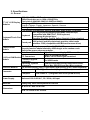
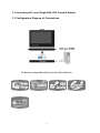
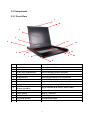
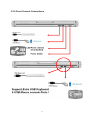
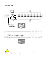
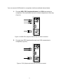
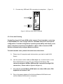
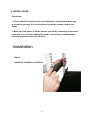
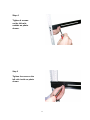
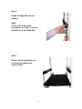
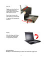
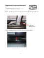
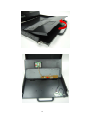
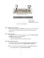
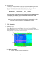
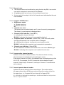
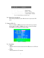
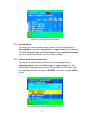
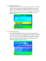
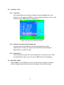
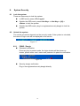
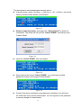
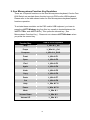
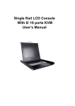
All In one LCD Drawer-Single Slide with 8/ 16-port KVM Combo Free User’s Manual Index 1. INTRODUCTION……………………………………………………………………….………………………2 Index 1.1 OVERVIEW …………………….…..………………………………….………….………………… ………2 1.2 FEATURES………… …………………………………...……………..………….…………………………3 1. INTRODUCTION……………………………………………………………………………………………2 1.3 Package Contents………………….……………………..………..………………………4 1.1 OVERVIEW …………………….…..………………………………….………………………… ………2 2. SPECIFICATIONS…………………………………………………… ……………………………………..5 1.2 FEATURES………… …………………………………...……………..…………………………………3 2.1 GENERAL 1.3……………………………………………………………...…….………………………………5 Package Contents………………….……………………..……...………………………4 3. CONNECTING ALL IN 1 SINGLE RAIL LCD CONSOLE DRAWER…….………..…………………… 6 2. SPECIFICATIONS…………………………………………………… …………………………………..5 3.1 CONFIGUARATION DIAGRAM OF CONNECTIONS……….……………….………………….………………..6 2.1 GENERAL ……………………………………………………………...…………………………………5 3.2 COMPONENTS…………………….....................……………..……….…….…………………………….7 3. CONNECTING ALL IN 1 SINGLE RAIL LCD CONSOLE DRAWER…………..…………………… 6 3.3 SYSTEM CONNECTION………………..……………………………………………………………………10 3.1 CONFIGUARATION DIAGRAM OF CONNECTIONS……….……………………………….………………..6 4. INSTALLATION……………………………………………………………….…..………………………..…15 3.2 COMPONENTS…………………….....................……………..………….…………………………….7 3.3 SYSTEM CONNECTION………………..…………………………………………………………………10 5. MODULARIZED COMPONENTS REPLACEMENT.…….…..……….……………………………….…21 INSTALLATION……………………………………………………….…….…..………………………..…15 5.1 LCD4.PANEL MODULE REPLACEMENT…………….………………………………………...…….21 5.2 KEYBOARD MODULE REPLACEMENT………………………………………………………...….22 5. MODULARIZED COMPONENTS REPLACEMENT.…….…..…………………………………….…21 6 HOT KEY OPERATION……………………………………………………………………………..…..….23 5.1 LCD PANEL MODULE REPLACEMENT…………….…………………………………………….21 6.1 Call OSD 5.2Menu……………………………………………………………………………………..…..25 KEYBOARD MODULE REPLACEMENT……………………………………………………….….22 6.2 Leading Hot Key Select…………………………………………………………………………….….25 6 Hot Key Operation………………………………………………………………………………………….23 6.3 Channel - Single KVM…………………………………………………………………….…...25 6.1Select Call OSD Menu………………………………………………………………………………………..25 6.4 Channel - Cascade Layer………………………………………………………….…..27 6.2Select Leading Hot KeyChain Select……………………………………………………………………………….25 6.5 Buzzer6.3 sound Disable / Enable……………………………………………………………………….28 Channel Select - Single KVM………………………………………………………………………...25 6.6 Auto-Scan Function…………………………………………………………………………………….28 6.4 Channel Select - Cascade Chain Layer……………………………………………………………..27 6.7 Console 6.5Lock……………………………………………………………………………………………30 Buzzer sound Disable / Enable……………………………………………………………………….28 6.6 Auto-Scan Function…………………………………………………………………………………….28 7 OSD OPERATION…………………………………………………………………………………………..30 6.7 Console Lock……………………………………………………………………………………………30 7.1 OSD Main Menu…………………………………………………………………………………………..30 7 OSD OPERATION…………………………………………………………………………………………..30 7.2 Channel selection in OSD………………………………………………………………………………..32 7.3 Setup in OSD: <F1>………………………………………………………………………………………33 7. SYSTEM SECURITY………………………….…….…..……………………………………………..…27 7.4 Auto-Scan in OSD: <F2>…………………………………………………………………………………35 7.1Lock in OSD: <F3>……………………………………………………………………………..36 7.5 Console 7.2rename: <F4>………….………………………………………………………………………..37 7.6 Channel 7.3Setup: <F5>……………………………………………………………………………………...37 7.7 Security 7.4 <F6>…………………………………………………………………………………………….40 7.8 Lock Port: 7.5 <ESC>…………………………………………………………………………………………..40 7.9 Exit OSD: 7.6 7.7 8.1 LOCK 7.8 THE SYSTEM …...……………..………….…………………………………………………….41 8. SYSTEM SECURITY………………………….…….…..………………………………………...…....…41 8.2 UNLOCK THE SYSTEM...……………..………….…………………………………………………….41 1 8.3 RESET THE ADMINISTRATOR SECURITY LOCK ………………………….…………………….. 42 9. SUN MICROSYSTEMS FUNCTION KEY EMULATION….…..………………………………….……44 1. Introduction Thanks for your purchasing the All in one LCD Drawer-Single Slide with 8/ 16-port KVM Combo Free. We recommend that you read this manual thoroughly and retain it for future reference. 1.1 Overview The All in one LCD Drawer-Single Slide with 8/ 16-port KVM Combo Free is an ideal module solution featuring an integrated 17/19-inch TFT LCD color display and ultra-high-quality compact industrial keyboard / touch pad in 1U, rack-mountable format, providing a user-friendly and most reliable operation environment for server administrators. Moreover, user now have a high quality, durable system to control 8 or 16 computers through PS/2 and/or USB connection from one console (PS/2 & USB Mouse, PS/2 & USB Keyboard, and Monitor). The Console drawer, similar to the front-end Console module, provides flicker-free color images at optimal resolutions, and has an ergonomically designed operation functionalities to maximize user convenience. Installation setup can easily be done by a single person. Simply use the Combo VGA cable of KVM switch set to link to the console ports, no matter whether your connected port interface is either USB or PS/2. On-Board monitor button allows straightforward connector selection. LED lamps can perfectly show the situation of every single connector and support user to handle or operate the whole system. On-Screen Display (OSD) Menu allows straightforward display adjustments. For even more convenience, there are two additional external USB ports for front-end connections with an extra set of USB keyboard and mouse, in addition to the original built-in keyboard/touch pad set. Further, we are also providing modular design for LCD monitor and keyboard / touch pad set to enhance convenience to help in case when one of them happens to be out of order, then new replacement could be implemented immediately without further ado. 2 1.2 Features The All in one LCD Drawer-Single Slide with 8/ 16-port KVM Combo Free features an integrated 17-inch/19-inch LCD panel module and keyboard/touch pad module within an 1U chassis. The unique modular design solution is for easy installation and maintenance. With our leading USB technology know-how, the unique and patented USB encryption security key can readily be bundled to the Drawer as to allow you a stringent access control that only allows access to authorized user possessing the security dongle and correct password, thus preventing unauthorized intrusion into your rack servers. z z z z z z z z z z z z z z z z z z Integrated KVM module with 17” / 19” LCD monitor & Keyboard/touch pad module within 1U chassis Supports modular design for easy installation and maintenance Supports extra USB keyboard and mouse port via front-end USB ports Complies with EIA RS-310C 19” Rack Mount standard Heavy-Duty Electroplate Steel Supports USB Key security function (Optional). Supports VGA resolutions up to 2048 x 1536 Connect computers via PS/2 and/or USB at will. Supports Windows, Linux, Mac OS9/OSX, Sun Microsystems. OSD is intuitive menus driven for quick and efficient navigation. Supports Daisy chain with 3 level cascades: up to 3 levels; control up to 16/256/4096 PCs (16-Port), from a single console; cascaded units don’t need special configuration. Emulates PS/2 or USB keyboard on each PC to allow your computers to boot normally without a keyboard error. Supports hot-pluggable. All devices connected to the KVM can be added or removed at any time, without shutting the unit down. Supports 3 types of switching: Hardware Push Button, Hot-Keys on PS/2 and/or USB of keyboard, Menu driven OSD (On Screen Display). Supports Auto-Scan function to switch video inputs automatically among computers in preset intervals sequentially by OSD menu driven. Supports LED display for PC and/or server status monitoring. Supports Beeper during Switching enabled. KVM firmware is upgradeable via on-board mini-USB download connector and external mini-programmer. 3 1.3 Package Contents 1. Single Rail LCD Console drawer 2. 3. 4. 5. 6. 7. x 1 8-Port or 16-Port Combo Free KVM Switch x 1. Custom KVM Cables Set x 1 USB Security Key Dongle x 2 (Optional) Power Cord x 1 User’s Manual x 1 Rack Mount Kit x 2 4 2. Specifications 2.1 General 17"/ 19"- 4CCFL LCD Panel SXGA Resolution up to 1024 x1280@75Hz 17”/19” LCD Display Pixel pitch:0.264(H)x0.264(V)/ 0.294(H)x0.294(V) 6 language OSD Modules English, Chinese, French ,Japanese ,Spanish, German Backlight lifetime: 50,000 hrs. LCD display automatically shut-off at display angle under 30 degrees. 105- key Keyboard supports Windows function keys, compatible with IBM PC/AT, PS/2 keyboard, Keyboard 6 Language Keyboard typeKeyboard/Touch Pad Germany, English, French, Italian, Spanish, Chinese(option) Module 1000 points/ inch(40 points/mm)-graphics tablet mode Touch pad Interface: PS/2 (compatible with Microsoft mouse driver) Combo free design is compatible with PS/2& USB connector. Security function administrated by USB dongle at the random code. Built-in the approved power adaptor. Auto-Scan Interval Adjustable time setting by OSD menu driven Video: 8/ 16 HDB-15 female PC Connectors KB/MS: PS/2 & USB signal combined 8/16 Port KVM Switch Firmware upgrade Module Mini USB female connector Operating systems Windows 98SE/ME/2000/XP/2003/Vista Server, supported Linux, Mac OS9/OSX and Sun Microsystems. Selection Method On-Screen-Display (OSD), Push Button and Hot-Key (PS/2 / USB Keyboard) Control center Module Extra console USB A Type Female x 2 (Keyboard/ Mouse) Computer VGA female x 1 (integrated with PS/2 kybd& mouse) Connector Power Supply Universal 100~240V AC , 50 / 60 Hz, 4A input Materials Heavy-duty steel electroplated for chassis W X D X H : 45x 70x 4.4 cm Dimensions N.W. 14.5 KGS/ G.W. 20 KGS 5 3. Connecting All in one Single Rail LCD Console Drawer 3.1 Configuration Diagram of Connections LCD Drawer-Single Slid with 8/ 16-port KVM Combo Free 6 3.2 Components 3.2.1 Front View 1 14 2 3 4 13 5 12 11 6 9 7 10 8 No. 1 2 3 4 5 6 7 8 9 10 11 12 13 14 Component Function Description Handle Holder LCD Display LCD Panel OSD Buttons 8/ 16-port KVM Combo Free LED Indicator Push buttons Slide Rail x 1 Lock Screws USB Ports x 2 (K/B, Mouse, Security SecuKey ) Power LED Power Switch Touch Pad Keyboard Module LCD Lock Screws Pull to Slide the LCD console in or out Panel Display Controls Display Required Quality Connect with KVM and console Switching Operation for KVM Module Controls channels of monitor Single Slide Rail (Slide fastener build in) Fix or Release the Single Rail LCD Console Drawer Plug-in external K/B, Mouse, and SecuKey Indicates Power Status / Security Status Turn on / Turn off Mouse Operation Keyboard Operation Fix or Release LCD panel 7 3.2.2 Front Console Connections 8 3.2.3 Back View Reset ! If Firmware Upgrade is necessary, please contact your dealer for further assistance and information. 9 3.3 System connection 3.3.1 System connection: Please use Custom combo cable to connect your computers. Please refer to the figures and instruction shown below for System connection. Note: Please contact your dealer to purchase the custom combo 4-1 cables if you need. Figure 1: Custom combo 4-in-1 cable 3.3.2 Rack Mounting Figure 2: Rack mounting Figure 6 shows you how to attach mounting brackets to the KVM Switch unit for standard 19-inch rack cabinet. 1. Screw the mounting brackets into the sides of the KVM Switch unit. ( See Figure 6) 2. Install the KVM Switch unit into the rack cabinet. 10 You can connect KVM switch to computers via three methods shown below: A. Connect USB, PS/2 (keyboard/mouse) and VGA connectors to computers. We recommand users to connect computers in this way. (Figure 3) Figure 3: USB & PS/2 (Keyboard & Mouse) and VGA connected B. Connect only PS/2 (keyboard/mouse) and VGA connectors to computers (Figure 4). Figure 4: PS/2 (Keyboard & Mouse) and VGA connected 11 C. Connect only USB and VGA connectors to computers. (Figure 5). Figure 5: USB and VGA video connected 3.3.3 Cascade Chaining Combo Free 8-port & 16-port KVM switch support 3 level cascades; control up to 64/256/4096 PCs, from a single console; cascaded units don’t need special configuration. Cascade configuration expands system ability and allows you to select computers connected to the Master or Slave. After connected, KVM Switches automatically configure Master and Slave. To Install cascade chain, please follow the instruction below: A. Please turn off computers and devices when you start to install KVM Switch. B. Use the custom combo cable set (See Figure 1), to connect one or more Slave KVM Switches to any PC port of Master KVM Switch. The connection between KVM to KVM must be connected through PS/2 connection. ( Please refer to Figure 2 & Figure 3 ). C. You can do console Master KVM Switch via either USB and/or PS/2 keyboard and mouse at will. D. Plug in the power adapter of the first level Master KVM Switch and connect Master KVM switch to computers. 12 E. Next, plug in power adapter for each level Slave KVM Switch and connect Slave KVM switch to computers . F. The power on sequence should be: 1. 2. Master KVM Switch Second level Slave KVM Switch (connecting to Master KVM Switch) if any. 3. Third level Slave KVM Switch (connecting to second level Slave KVM Switch) if any. 4. All computers connecting to Master/Slave KVM Switch. G. After all KVM Switches are powerd by power adaptor, trun on the computers. z Initial Plug-in Process: Please plug in the Master KVM Switch first before turning on any other devices like montior or computers. z Hot plug and Hot Swap: Combo Free 8-port & 16-port KVM switch support Hot plug and Hot swap function. Figure 6: Cascade chaining 13 3.3.3 Firmware download connector The min-USB female connector on the rear of KVM switch is for firmware upgrade function. To update your KVM firmware, please contact with your dealer. 3.3.4 Operation You can control computers via 8-Port or 16-Port Combo Free KVM Switch by push button, hot key and OSD. 1. Push button operation Press the push button to select the PC and operate it. 2. Hot Key operation Please refer section 6. Hot Key Operation. 3. OSD operation Please refer section 7. OSD Operation. 14 4. INSTALLATION Precaution: 1. Please check the whole unit for any damaged or missing parts when you received the package. If you encounter any problem, please contact your dealer. 2. Make sure that power to all the devices you will be connecting to has been turned off. You must also unplug the power cords off any computers that have the Keyboard Power On Function. Installation Step 1 Install the Left Rail on Cabinet. 15 Step 2 First, drive the screws loosely through the front bracket of left rail on cabinet. Try not to tighten the screws too much, so that later it will allow you some wiggle room to align the holes in a correct orientation. And this will make easy insertion of the long bolt which serves as an anchor to limit the sliding range of the rails. Step 3 Screw and tighten the back bracket of left rail on cabinet. 16 Step 4 Tighten 4 screws on the left rails outside as photo shown. Step 5 Tighten 4 screws on the left rails inside as photo shown. 17 Step 6 Install the Right Rail on the cabinet. Note: Please follow the same procedures as Step 1~5 for the installation of the Right Rail. Step 7 Please check if the Rails are secured and attached to cabinet firmly. 18 Step 8 Slide the LCD Console Drawer into the Rails and push it further to the end. Step 9 Take out the 2 stopper bars (each of which is comprised of a long screw and a cage nut on the end) and install each of them through the central holes on both the left and the right bracket. Take care to align the central hole (since we have left some wiggle room when previously install the left and the right bracket) so that it will allows the stopper bar to go through the central hole correctly. Then tighten all 3 screws on the front brackets of the Left and the Right Rail. 19 Step 10 Firstly you should pull out LCD handle toward as photos show and until the slide fasteners work. Users have to move the slide fasteners in both side for go back the appropriate position. Step11 After finishing step10 than to lift up the LCD display to appropriate position. Congratulation! All steps in the installation procedure are well done right now. 20 5. Modularized Components Replacement 5.1 LCD Panel Module Replacement. Step 1. Turning loose 2 pcs of screws on each side, and then pull to lift it out. Step 2. Apply gentle force to lift the LCD panel module upward. 21 Step 3. Take a new LCD panel and make due downward alignment to the tray chassis so that it can easily be docked with the VGA connector. When you have fit it into the chassis, then try put the screws on both side of the panel and tighten them up. The replacement is now complete. 5.2 Keyboard Module Replacement. Step 1. Remove one screw on each side of the keyboard tray, and then you can pry and pull up the keyboard module to reveal the underside of it. 22 23 Step 2. Disconnect K/B and M/S Connectors. 24 6 Hot Key Operation 6.1 Call OSD Menu Press < Scroll Lock> twice and <Enter>, then the OSD “Main Menu” will be displayed on the monitor screen. All of the KVM parameters can be setup in OSD mode. You can also execute some KVM functions in OSD. <Scroll Lock> → <Scroll Lock> → <Enter> 6.2 Leading Hot Key Select The two-steps hot key sequence is used for quick function execution. The leading key is <Scroll Lock> by default. However, you can change the leading hot key if you want. By pressing <CTRL> twice, <New Hot Key>, then press <Enter>, you can change the leading hot key. The available leading hot key are <Scroll Lock>, < Num Lock > or < Caps Lock > for option. ¾ Setup leading hot key to < Scroll Lock > < CTRL > → < CTRL > → < Scroll Lock > → < Enter > ¾ Setup leading hot key to < Num Lock> < CTRL > → < CTRL > → < Num Lock > → < Enter > ¾ Setup leading hot key to < Caps Lock > < CTRL > → < CTRL > → < Caps Lock > → < Enter > Note: You can also change leading hot key by pressing <F1> in OSD main menu. Please refer section 7.3.5 Setup in OSD – Hot Key. 6.3 Channel Select - Single KVM 6.3.1 Specific channel selection You can select the connected computers by using the two-step Hot Key sequence. Press <Scroll Lock> key twice (Step 1), then press key (1 to 16) and <Enter> (step 2) to select the computer you want to control. 25 Figure 7: Specific channel selection hot key or or … … <Scroll Lock> → <Scroll Lock> → <1> → <Enter> <Scroll Lock> → <Scroll Lock> → <2> → <Enter> <Scroll Lock> → <Scroll Lock> → <16> → <Enter> Note: You can also select computers in OSD menu. Move the indicator bar to the chanel to switch by using <arrow key>, <Page Up> or <Page Down>, then press <Enter> to select the connected computer. Please refer section 7.2 Channel Selection in OSD. 6.3.2 Arrow Key Channel Shift Function Press <Scroll Lock> twice, and press <Left Arrow> or <Right Arrow> key to shift left/right one channel. ¾ Switch to left one channel <Scroll Lock> → <Scroll Lock> → <Left Arrow> ¾ Switch to right one channel <Scroll Lock> → <Scroll Lock> → <Right Arrow> 6.3.3 <ALT> Channel Shift Function 1. Start <ALT> Channel shift Function < ALT > channel shift function default was off. You can press Hot-Key <Scroll Lock> twice, <ALT> and then press <Enter> to turn on or turn off this function alternately. 2. Shift the channel by <ALT> key Press left < ALT > or right < ALT > key twice, the PC channel will 26 automatically shift to left or right one channel (channel decrease / increase to next) when < ALT > channel shift function is enabled. 6.4 ¾ Enable/Disable <ALT> channel shift function <Scroll Lock> → <Scroll Lock> → < ALT > → <Enter> ¾ Switch to left one channel <Left ALT> → < Left ALT > ¾ Switch to right one channel <Right ALT> → < Right ALT > Channel Select - Cascade Chain Layer You can select the active channel directly under cascade chain connection. The following hot key sequence is used for quick channel selection. Press <Scroll Lock> twice, <D>, the cascade channel number (1, 2, 3……16), and Press <Enter>. ¾ Channel select to first layer < Scroll Lock > → < Scroll Lock > → <D> → < CH-L1 > → < Enter > ¾ Channel select to second layer < Scroll Lock > → < Scroll Lock > → <D> → < CH- L1 > → <D> → < CH-L2 > → < Enter > ¾ Channel select to third layer < Scroll Lock > → < Scroll Lock > → <D> → <CH-L1 > → <D> → < CH-L2 > → <D> → < CH-L3 > → < Enter > Note: With cascading 3 layers, you can select last layer directly; Example: press <Scroll Lock> twice, then D2D5D7, and <Enter>: D2 : layer 1 channel 2 links to D5 : layer 2 channel 5 links to D7 : layer 3 channel 7 selected Note: You can also select active channel of cascade chain in OSD menu. Move the indicator bar to the chanel to switch by using <arrow key>, 27 <Page Up> or <Page Down>, and then press <Enter> to switch to the target port. Please refer section 7.2.2 Channel select to cascade port. 6.5 Buzzer sound Disable / Enable Press <Scroll Lock> twice, then <B> and <Enter>. The buzzer sound will be disabled / enabled alternately. The buzzer sound default setting is ON. <Scroll Lock> → <Scroll Lock> → <B> → <Enter> Note: You can also enable/disable buzzer sound by pressing <F1> in OSD main menu. Please refer section 7.3.6 Setup in OSD - Sound. . Figure 8: Buzzer setup hot key 6.6 Auto-Scan Function When you enable Auto-Scan function by pressing <Scroll Lock> twice, then <S> and <Enter>. The KVM Switch will shift through all the ports and display them on the monitor. The mouse and keyboard will be disabled under this mode. This is necessary to prevent errors such as erratic movement and wrong characters to display when using the mouse or keyboard in accident. 6.6.1 Start auto-scan function <Scroll Lock> → <Scroll Lock> → <S> → <Enter>. The auto-scan banner will be shown to indicate the scanning channel. 28 Figure 9: Auto-scan hot key ─┬── │ │ ┬ ──┬────── │ └─ └────────── └─────────────── Channel Name Channel Number Indicate now is Scan Mode Figure 10: Auto-scan Banner 6.6.2 Stop auto-scan function Press any key on keyboard to STOP the auto-scan function. Press the push button on KVM front panel to select active port can stop the auto-scan function too. 6.6.3 Auto-scan mode There are two auto-scan modes, please refer section 7.3.1 Setup in OSD – Scan Mode to setup the auto-scan mode. ¾ Scan all working computers. ¾ Scan all computers which are marked for auto-scan. 6.6.4 Auto-scan time interval The auto-scan time interval can be adjustable by pressing <F1> in OSD main menu. Please refer section 7.3.1 Setup in OSD – Scan Time. Note: You can also start auto-scan function by pressing <F2> in OSD main menu. Please refer section 7.4 Auto-Scan in OSD. 29 6.7 Console Lock If the security mode is enabled in OSD mode (by pressing <F5> in OSD mode), you can lock console by pressing <Scroll Lock> twice, and then <H> and <Enter>. The KVM will be locked until an authorized user login. <Scroll Lock> → <Scroll Lock> → <H> → <Enter> To unlock console, please press any key according to screen message, then key in User Name and Password. The KVM switch and console devices will be unlocked and back to normal status. Note: You can also execute console lock function by pressing <F3> in OSD main menu. Please refer section 7.5 Console Lock in OSD. 7 OSD Operation 7.1 OSD Main Menu Press < Scroll Lock> twice and <Enter>, then you will enter to OSD (On Screen Display) main menu. The channel number, names and the status will be displayed on the monitor screen. Please refer fig. 8 Fig. 11: OSD main menu 7.1.1 KVM layer number 1st, 2nd or 3rd. indicates thescurrent cascade level. s 30 7.1.2 Channel name ¾ The channel name can be defined by using function key F4, it can remind user which computer is connected to this channel. ¾ A highlighted pink bar is shown in the selected channel row. ¾ A plus mark (+) showing in the left of channel name indicates that the port has cascades. 7.1.3 Computer & KVM status ¾ KVM buzzer stauts Buzzer sound on Buzzer sound off ¾ Logined user name The system has one administrator and 3 users for security management. The name of current logined is displayed here. ¾ Channel LOCK indicator ( Status STA ) L: Indicating this channel is locked. BLANK: Indicating this channel is normal without locked. ¾ Computer power on indicator ( Status STA ), OSD menu will update the flag automatically if the computer status is changed A: Indicating this computer is powered on and ready to select. BLANK: Indicating this computer is not connected or powered on. ¾ Channel scan indicator ( Status STA ) S: This channel is marked for auto-scan if the scan mode is Select type. BLANK: Indicating this computer is not marked for auto-scan. 7.1.4 Current active channel number Indicate current active channel number. The channel of the currently selected computer is displayed in the right-upper corner. If the active channel is in 2nd or 3rd cascade layer, the display string is like XX-YY-ZZ. For example, 02-05-07 means the active channel is layer 1 channel 2 links to layer 2 channel 5, and layer 3 channel 7 is selected as active channel. 7.1.5 Cascade parent channel number Indicate the parent channel of this cascade layer. The number at the left-upper corner below KVM layer number shows the number of port for the upper layer, i.e. 8 means link from channel 8 of upper KVM. It’s valid only for 2nd and 3rd cascade layer. It will show blank for 1st layer since there is no parent channel. 31 7.1.6 Page down / up indicator This is for 16-port KVM only. The information of port 1 ~ 8 are display in the first page, and information of port 9 ~ 16 are display in the second page. Since the port information is divide to two pages, the page down / up indicator can remind you to switch to alternative page by using <page down> and <page up> key. 7.1.7 Function Control Menu The detail of control functions will be described in later sections. The list of control functions: F1: Set up: basic set up menu F2: Scan: autoscan function F3: Lock: setup lock/unlock, only available when F5 Security is enabled. F4: Rename: rename selected channel name. F5: Security: security function and user authority settings F6: Lock Port: PC port lock function (for administrator only) 7.2 Channel selection in OSD 7.2.1 Channel select to computer Use the <UP> and <DOWN> arrow keys to highlight a computer and then <ENTER> to select it and leave OSD menu. A banner with the channel name will be shown on left-upper corner of the screen. ┬ ────┬────── │ └ Channel Name └──────────── Channel Number Fig. 12: Channel Banner (Single Layer) 7.2.2 Channel select to cascade port A plus mark (+) showing in the left of channel name indicates that the port s Pressing <ENTER> in this channel will enter is under cascade channing. s one level down, and the screen pops up the listing of the computers of the slave KVM. 32 ┬ ┬ ┬ │ │ │ │ │ └─────── │ ────┬────── └ └────────── Channel Name Channel Number nd 2 Layer Channel Number └────────────── 1st Layer Channel Fig. 13: Channel Banner (Cascade Layer) Number 7.2.3 Return from cascade port After entering cascade port, press <R> will return to upper layer OSD s menu. s 7.3 Setup in OSD: <F1> Please use <Up> or <Down> arrow key to select the item you want to change, and use <Left> or <Right> arrow key to change the settings. Press <ESC> to exit and save the setup settings. Figure 14: OSD Setup 7.3.1 Scan Mode ¾ Select: Scan the selected channels marked with S in STA column on OSD main menu. ¾ PC ON: Scan all powered on PC channels 33 7.3.2 Scan Time The default scan time is 5 seconds. It can be changed up to 90 seconds by stepping 5 seconds. 7.3.3 Banner Time The default banner time is 5 seconds. It can be changed to 10 seconds, 15 seconds, or always on (∞). 7.3.4 Position ¾ Menu: Use four arrow keys to move the OSD main menu to the desired position. Press <ESC> to save the changed menu position. Figure 15: Menu Position Setup ¾ Banner: Use four arrow keys to move the channel banner to the desired position. Press <ESC> to save the changed banner position. Figure 16: Banner Position Setup 7.3.5 Hot key ¾ Scroll Lock: <Scroll Lock> becomes the hot key. ¾ Num Lock: <Num Lock> becomes the hot key. ¾ Cap Lock: <Cap Lock> becomes the hot key. 34 Note: You can also change leading hot key via hot key by using < CTRL > → < CTRL > → < New Hotkey > → < Enter > outside the OSD mode. Please refer section 6.2 Leading Hot Key Select. 7.3.6 Sound ¾ ON: Buzzer sound enabled. ¾ OFF: Buzzer sound disabled. Note: You can also enable/disable buzzer sound via hot key by using <Scroll Lock> → <Scroll Lock> → <B> → <Enter> outside the OSD mode. Please refer section 6.5 Buzzer sound Disable / Enable. 7.3.7 Language English (En) / Deutsch (De) / Francais (Fr), 3 languages are available. 7.4 Auto-Scan in OSD: <F2> 7.4.1 Start to auto-scan in OSD Press <F2> in OSD main menu. The auto-scan banner will be shown to indicate the scanning channel. ─┬── ┬ ──┬────── │ │ │ └────────── └─ └─────────────── Channel Name Channel Number Indicate now is Scan Mode Figure 17: Auto-Scan Banner Note: You can also start auto-scan function via hot key by using <Scroll Lock> → <Scroll Lock> → <S> → <Enter> outside the OSD mode. Please refer section 6.6.1 Start Auto-Scan Function. 7.4.2 Stop auto-scan Press any key on keyboard to STOP the auto-scan function. The auto-scan banner will disappear when the scan stops. 35 7.4.3 Auto-scan mode There are two auto-scan modes, please refer section 7.3.1 Setup in OSD – Scan Mode to set up the auto-scan mode. ¾ Scan all computers which are power on. ¾ Scan all computers which are marked for auto-scan. 7.4.4 Auto-scan time interval The auto-scan time interval of each port displayed can be adjustable by pressing <F1> in OSD main menu. Please refer section 7.3.2 Setup in OSD – Scan Time. 7.5 Console Lock in OSD: <F3> If the security mode is enabled in OSD mode (by pressing <F5> in OSD mode, please refer section 7.7 Security Setup in OSD). You can logout to lock console by pressing <F3> In OSD mode. The Console Lock Banner will be shown on the screen. Figure 18: Console Lock Banner The KVM will be locked until an authorized user login. Figure 19: Unlock window Note: You can also logout to lock console via hot key by using <Scroll Lock> → <Scroll Lock> → <H> → <Enter> outside the OSD mode. Please refer section 6.7 Console Lock. Note: If you forget the password, the only way to permanently disable the security function is to key in a universal password to unlock KVM. You need to key in this unlock password to release your device and KVM, and then you can restart everything. Please contact with your agency/distributor to get the universal password. 36 7.6 Channel rename: <F4> Select the channel to rename by using up/down arrow key and press <F4> in OSD main menu. The channel rename window will be shown for setting up the channel name. Press <ENTER> to save the renamed channel name or <ESC> to cancel. Figure 20: Channel Rename window 7.7 Security Setup: <F5> 7.7.1 Security mode login Press <F5> in OSD main menu to enter security setup mode, the administrator login is required before entering into the security mode. Figure 21: Security mode login window The default administrator account is: User Name: admin Password: 123456 After login, the security setup main window will be shown on the screen. Please select the security item to setup via <up arrow> and <down arrow> key, and press <left arrow> or <right arrow> key to change the settings. 37 Figure 22: Security setup main window 7.7.2 Security Mode To change the security mode setting, please move the highlight bar to Security Mode, and press <left arrow> or <right arrow> key to change it. The <F3> Console Lock, <F6> Port Lock and user authority functions can not be executed until the security mode is enabled. 7.7.3 Change administrator password To change the administrator password, move the highlight bar to Admin/password, and press <left arrow> or <right arrow> key. The administrator password setup window will be shown on the screen. Input the new password twice and press <ENTER> to confirm, or press <ESC> to exit. Figure 23: Administrator password setup window 38 7.7.4 Authorized user setup 3 authorized users are admitted to manage the KVM switch. To change the user name and password, please move the highlight bar to the user for editing. Press <left arrow> or <right arrow> key, the user name and password setup window will be shown on the screen. Please Input the new user’s name and password twice, then press <ENTER> to confirm or <ESC> to cancel. Figure 24: User name password setup window 7.7.5 User Authority setup You can setup the authority for each user. Different user has different access right for each channel. To change the access right of each channel for certain user, please move the highlight bar to the channel, and press <A>, <1>, <2> or <3> to setup the channel access right for all or certain user. You don’t have to setup the authority of administrator since the administrator has all channel access right. Figure 25: User authority setup window 39 7.8 Lock Port: <F6> 7.8.1 Lock Port Only administrator can lock port. Please move the highlight bar to the channel to lock, and press <F6> to lock the selected channel. A red L mark will be shown in STA column of locked port. Figure 26: Lock port in OSD main window 7.8.2 Channel selection of the locked port If anyone selects the channel of the locked port either by panel push-button or hot key, the system will enter OSD mode waiting for administrator to unlock the port. 7.8.3 Unlock Port Only administrator login with correct password can unlock the port. After the administrator login, the red L mark in STA column will disappear. 7.9 Exit OSD: <ESC> Press <ESC> to exit OSD and to return to the selected computer. A banner with the channel name will be shown on left-upper corner of the screen. 40 8. System Security 8.1 Lock the system There are three ways to lock the system: 8.2 In OSD mode, press <F3> Logout Outside the OSD mode, press <Hot Key> + <Hot Key> + [H] + <Enter> to lock the system. Outside the OSD mode, plug in a registered security dongle to lock the system. Unlock the system The unlock procedure depends on the security mode. If the system is unlocked, the name of login user will be displayed on the screen. Figure 23 8.2.1 PSWD / Dongle Password verification Press any key in protect mode, the login window will be shown on screen, please enter user’s name and password to pass the verification. Figure 24 Security dongle verification Plug in the registered security dongle directly. 41 8.2.2 PSWD + Dongle Password verification first Press any key in protect mode, the login window will be shown on screen, please enter user’s name and password. If the first stage verification is passed, plug in the registered dongle of this user to pass the second stage verification to unlock the system. Figure 25 Security dongle verification first Plug in the registered security dongle directly. If the security dongle is identified, the owner’s name of this dongle will be displayed on the screen, please enter the password of this user to unlock the system. Figure 26 8.3 Reset the administrator security lock If the security mode is setup as PSWD+DONGLE, in case the administrator lost his security dongle or forget his password, then the system settings can not be changed since administrator can not login to the system. To solve this problem, administrator must reset administrator security lock. To reset administrator security lock, you must contact your dealer, and you must have either administrator password or dongle ready at hand. If you lost both of them, then there is no way to reset the administrator’s lock, you must return your machine to dealer for system reset, and all data will be erased beyond recovery. 42 The procedure to reset administrator security lock is: z In protect mode, press <Hot Key> + <Hot Key> + <X> + <Enter>, the unlock security window will be shown on the screen. Figure 27 z Please contact the dealer, and impart the “Unlock Serial” to dealer for information. The dealer will tell you the “Unlock PSWD” according to your “Unlock Serial”. Figure 28 z Input the “Unlock PSWD” from your dealer. Figure 29 z z After entering the correct “Unlock PSWD”, you must input enrolled password or plug in the dongle of administrator. Figure 30 If both of the above verification steps has been completed, you will enter the OSD main menu as the administrator. You can register a new password or security dongle for administrator. 43 9. Sun Microsystems Function Key Emulation: There are 16 special functions on the Sun Microsystems keyboard, Combo Free KVM Switch can emulate these function keys via PS/2 and/or USB keyboard. Please refer to the table shown below for Sun Microsystems keyboard special functions operation. To activate these emulation on the PS/2 and/or USB keyboard, you have to press the <LEFT Window> key first (this key usually is located between the <LEFT CTRL> and <LEFT ALT>). Then press the second key ( Sun Microsystems Function Key ) . Please do not release <LEFT Window> when you press the second key. Sun Microsystems Function Key USB or PS/2 Keyboard Stop L_Win & L_Alt Props L_Win & L_Ctrl Compose L_Win & L_Shift Front L_Win & F1 Open L_Win & F2 Find L_Win & F3 Again L_Win & F4 Undo L_Win & F5 Copy L_Win & F6 Paste L_Win & F7 Cut L_Win & F8 Help L_Win & F11 Power L_Win & F12 Mute L_Win & 1 Volume Down L_Win & 2 Volume UP L_Win & 3 44 Disclaimer Information in this document is subject to change without notice. The manufacturer does not make any representations or warranties (implied or otherwise) regarding the accuracy and completeness of this document and shall in no event be liable for any loss of profit or any other commercial damage, including but not limited to special, incidental, consequential, or other damages. No part of this document may be reproduced or transmitted in any form by any means, electronic or mechanical, including photocopying, recording or information recording and retrieval systems without the express written permission of the manufacturer. All brand names and product names used in this document are trademarks, or registered trademarks of their respective holders. FCC Statement This device generates and uses radio frequency and may cause interference to radio and television reception if not installed and used properly. This has been tested and found to comply with the limits of a Class B computing device in accordance with the specifications in Part 15 of the FCC Rules. These specifications are designed to provide reasonable protection against such interference in a residential installation. However, there is no guarantee that interference will not occur in a particular installation. If this device does cause harmful interference to radio or television reception, which can be determined by plugging the device in and out, the user can try to correct the interference by one or more of the following measures: z Reorient or relocate the receiving antenna. z Increase the separation between the device and receiver. z Connect the computer into an outlet on a circuit different from that to which the receiver is connected. z Consult the dealer or an experienced radio/TV technician for help. 45