1
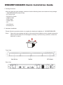
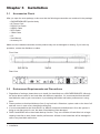
User Manual
Version : 1.1
SOHORAID Series
OWCMRP4B8U2ES
Introduction
About this Manual
Thank you for using the product of Other World Computing.
The SOHORAID OWCMRP4B8U2ES products will be introduced throughout this manual. It is recommended
that you go through this manual before starting using the SOHORAID OWCMRP4B8U2ES products.
Although the information has been verified before published, specifications are subject to change without
prior notice. Please refer to http://www.macsales.com/ for any product specification or update of related
information.
Notice: Other World Computing. only provides technical support and service to OWC direct customers.
For end users or non-direct customers, please contact your distributor for better support and
prompt responses. If your product is not purchased directly from OWC, please do not contact us
directly since you may not get any reply.
OWCMRP4B8U2ES Quick Installation Guide
1. Package Contents
After you open the outer package, make sure that the following items are contained in the package:
• OWCMRP4B8U2ES product body
• AC Power Cord
• RS-232 Port Cable
• USB2.0 Cable
• SATA Cable
• 1394b Cable
• CD
• User Manual
• Accessory Kit
2. Hardware Installation
Please follow the procedure below to complete the hardware installation of OWCMRP4B8U2ES:
Step 1 Open the outer package and take out the product body. (Make sure the related accessories
and the product body are not damaged or missing. If you have any questions, contact the
distributor or sales)
Front View
Rear View
Step 2
Mount the product to the rack. Make sure that the fan is not blocked and there is appropriate
space around for heat dissipation. (Do not place the product nearby water area or any
environment that may cause damage to the product)
Step 3 Take out the tray and install your hard disk in it. Make sure to fasten the hard disk securing
screws to prevent damages caused by unnecessary movement.
Step 4 Once the installation is completed, insert the tray back and fix it firmly in the proper place.
Step 5 Select the RAID 0 or NRAID mode.
Raid 0
NRaid
RaidMode Switch
Step 6 Connect the cables to the corresponding jacks. Then connect the power cord.
Step 7 Hardware installation is completed. You can power on the system to start the related setup
and application.
Contents
Chapter 1
1.1
1.2
1.3
Chapter 2
2.1
2.2
Chapter 3
3.1
3.2
3.3
3.4
Chapter 4
4.1
4.2
4.2.1
4.2.2
4.3
4.4
4.4.1
4.4.2
4.4.3
4.5
4.5.1
4.6
4.6.1
4.6.2
4.6.3
RAID Introduction.......................................................................... 6
What is RAID?...................................................................................... 6
RAID Functions.................................................................................... 6
RAID 0 vs. NRAID................................................................................. 6
Features and Specifications........................................................ 7
Features of Hardware............................................................................. 7
Hardware Specifications......................................................................... 7
Installation...................................................................................... 8
Accessories Check................................................................................ 8
Environment Requirements and Precautions................................................ 8
Hardware Installation.............................................................................. 9
Software Installation............................................................................... 10
RAIDGuide Management.............................................................. 12
Connecting the RAID System................................................................... 13
Notification.......................................................................................... 14
E-Mail................................................................................................. 14
Setting up the Alarm............................................................................... 15
Event log............................................................................................. 16
Web................................................................................................... 17
Upload................................................................................................ 17
Remote Setup...................................................................................... 18
Multi-Remote Window............................................................................ 18
Advanced............................................................................................ 20
Options............................................................................................... 20
Sharing the Folder of Web Server (take Windows 2000 Server for example)......... 21
Sharing Folders (for the Upload Function)................................................... 21
Setting up Accessible Folder in the Browser (for the Remote Function)............... 23
Personal Web Server............................................................................. 30
Chapter 1
1.1
RAID Introduction
What is RAID?
It is inevitable that a single hard disk, either with SCSI or IDE interface, will suffer the compatibility problem
between the motor rotational speed and the transfer interface. As a result, an Ultra160 SCSI or ATA100 IDE
hard disk can only achieve the transfer rate of up to 30MB/Sec at the bandwidth of 100MHz. In addition, the
life span of a hard disk is limited. Once a hard disk is damaged, it is likely to lead to the system crash and
data loss. Abovementioned are two severe problems in network system architecture. These factors have
encouraged the generation of RAID (Redundant Arrays of Inexpensive / Independent Disks), a technology
that combines multiple inexpensive and independent hard disks into an array of hard disks so as to increase
data transfer performance and storage efficiency.
RAID implements the mechanisms such as Striping or Mirroring plus Parity Checking, to combine two or
more physical hard disks into one virtual/logical disk array that allows On-line, quick access, huge capacity
and fault tolerance. If one of the hard disks in the array is damaged, the system continues to operate using
the remaining working hard disks, resulting in no system crash or data loss.
In summary, RAID technology increases the performance and data security in network system architecture.
1.2
RAID Functions
Expanding storage capacity
Increasing data transfer speed
Saving cost
Inherent Fault Tolerance
Hot Swap
Auto-Rebuild
Hot Spare
• On-line Capacity Expansion
•
•
•
•
•
•
•
1.3
RAID 0 vs. NRAID
The OWCMRP4B8U2ES provides two level applications: RAID 0 (RAID 0 + NRAID) and NRAID.
RAID 0: Striping + NRAID (fast, has no fault tolerance; requires at least four hard disks)
The OWCMRP4B8U2ES provides a RAID 0 level application that is different from ordinary ones.
OWCMRP4B8U2ESs RAID 0 level contains Striping + NRAID at the same time; the capacity will be
expanded while the performance is increased. In the aspect of capacity calculation, the system will first
execute the Striping function to combine the four hard disks into two units, and then execute the NRAID
function. Due to lack of the data backup function, entire data system will be damaged in case of any hard
disk malfunction.
NRAID: Non-RAID (has no fault tolerance; requires at least four hard disks)
As RAID 0, NRAID combines all physical disks into a large-capacity hard disk. However, the difference is
that NRAID stores data directly starting from the first hard disk. After the first hard disk being full, it will go
for second one, and so forth. NRAID’s calculation of available disk capacity is also different from that of
RAID 0: NRAID’s total capacity equals the sum of all physical disks’ capacity.
The NRAID level of data storage does not disassemble and separate the data; it will switches to next
hard disk as long as the previous one is full. Therefore, when data storage area stretches across two
hard disks, errors and access problems are prone to occur upon such data. Also, because of the lack of
actual RAID application, when a hard disk crashes, the data will be lost.
For more information of RAID, refer to our website at http://www.macsales.com/
6
RAID Introduction
Chapter 2
2.1
Features and Specifications
Features of Hardware
The SOHORAID OWCMRP4B8U2ES mainly supports SATA interface for hard disks. It provides RAID 0
/ NRAID functions for users to select from. The SOHORAID OWCMRP4B8U2ES supports four largecapacity SATA hard disks. With the total storage capacity up to 2TB and the maximum transfer speed
at 150MB/Sec, the series satisfies the need for large capacity, as well as providing high-speed access
performance.
The SOHORAID OWCMRP4B8U2ES comes with the following features:
• With four SATA II 3.0 GHz hard disks installed, it can support a large capacity over 2TB.
• Supporting multiple host interfaces: eSATA+ 1394b+USB.
• Providing RAID 0 application mode: providing high-speed transfer performance that surpasses 80MB/sec.
• Providing NRAID storage calculation: capable of combining hard disks with different capacities into a
large hard disk.
• Providing the system-detecting function: Fans, temperature sensor and buzzer-triggering device can
help detect system status to avoid the risk of losing data.
2.2
Hardware Specifications
Product Model
OWCMRP4B8U2ES
Host Interface
eSATA + 1394b +USB 2.0 Triple
Hard Disk Interface
4 x 3.5” SATA HDDs
Transfer Speed
150 MB/s & 80MB/s & 48MB/s
Chips Specifications
RAIDON ASIC 2044
Hard Disk Quantity
4
RAID Levels
0, NRAID
Maximum Storage Capacity
up to 2TB
Fan
2 x 40*20 Fan+1x40*20 Power Fan
Power Supply
200W POWER, 100V~240V
Power Indicator
Yes
LED Indicator
4 x Drive Access LED Indicators+ 1 x Environment LED Indicator
Operating System Supported
Mac 10 later, Linux core 2.4 later, Windows series
GUI Software
Windows Based
Size
430Wx 420D x 43H mm
Safety Codes Certification
CE/FCC
Features and Specifications
7
Chapter 3
3.1
Installation
Accessories Check
After you open the outer package, make sure that the following accessories are contained in the package:
• OWCMRP4B8U2ES product body
• AC Power Cord
• RS-232 Port Cable
• USB2.0 Cable
• SATA Cable
• 1394b Cable
• CD
• User Manual
• Accessory Kit
Make sure the related accessories and the product body are not damaged or missing. If you have any
questions, contact the distributor or sales.
Front View
Rear View
3.2
Environment Requirements and Precautions
1 Regardless of settings, please be sure to install four hard disks on a OWCMRP4B8U2ES. Although
the series allows users to use hard disks with different capacities, it is recommended that identical
hard disks be used to gain convenience in purchasing hard disks and better performance in using
them.
2 Please make sure that hard disks are free of any bad track. Otherwise, system crash or the loss of all
data will occur in case of any hard disk malfunction.
3 It is recommended that the mode RAID 0 or NRAID is determined beforehand. Once the system is
being re-set after setup for use, the data of hard disks will be damaged.
4 RAID 0 and NRAID do not have data backup function. They can combine all hard disks into a largecapacity hard disk to have faster transfer performance. All data in the hard disks will be damaged in
case of any hard disk malfunction.
8
Installation
3.3
Hardware Installation
After verifying that the product body and related accessories are not missing or damaged, please follow
the following procedures to complete the hardware assembly.
Step 1 Mount the product to the rack. Make sure that the fan is not blocked and there is appropriate
space around for heat dissipation. (Do not place the product nearby water area or any environment
that may cause damage to the product)
Step 2 Take out the tray and install your hard disk in it. Make sure to fasten the hard disk securing screws
to prevent damages caused by unnecessary movement.
Step 3 Once the installation is completed, insert the tray back and fix it firmly in the proper place.
Step 4 Select RAID 0 or NRAID Application.
Raid 0
NRaid
RaidMode Switch
Step 5 Connect the cables to the corresponding jacks. Then connect the power cord.
Step 6 Hardware installation is completed. You can power on the system to start the related setup and application.
Installation
9
3.4
Software Installation
RAIDGuide Management is an application software to set up the RAID system. You can use it, along with
the RS232 port, to easily retrieve and display the data related to the RAID system.
Installation
To start the installation, place the RAIDGuide Management CD into the CD-ROM drive and select the
installation program of the RAIDGuide folder. Once the installation is completed, you will be able to use
RAIDGuide Management.
To install RAIDGuide Management, please follow the following procedures:
Step 1 Executing the RAIDGuide Management installation file; the welcome screen will be displayed.
Step 2 Select “Next” and the system will ask you about the path address for installation. You can either
select the installation folder or the default path.
10
Installation
Step 3 Once you have confirmed the installation path and folder, select “Next.” The system will ask
you for the name of the folder, which is displayed on the program list. Confirm it and select
“Next.” The installation is now completed.
Now that the installation is completed, you can use RAIDGuide Management to set up and manage your
system.
Installation
11
Chapter 4
RAIDGuide Management
RAIDGuide Management is an application software to set up the RAID system. You can use it, along
with the RS232 port, to easily retrieve and display the data related to the RAID system. Systemrelated information includes: system status, hard disks' errors, system errors, hard disks' insertion and
identification, as well as the progress of data-rebuilding.
Features:
1. Supports connection of two sets of RAID systems
2. Supports e-mail notification when either hard disk error or system errors
3. Supports warning by PC speaker when error occurs; it would broadcast warning signals with wav or midi files
4. Supports up to 20 users who can login from different sites
5. Hidden in the tool bar; the window will automatically pop up when error occurs.
6. Detects errors in fan, temperature, hard disk, and system status
7. Firmware updates (password: 1234)
System Requirements :
Hardware
Specification
Microprocessor
Pentium
Memory
64MB
Connection Line
1 Set
Hard Disk Space
10MB
Screen Resolution(Suggestion)
800 x 600
Operation System
Window98, ME, XP and NT
After the software being installed, select [RAIDGuide RAID MANAGER]; the program will start and the
main window will pop up, as the following figure shows. Select [connection line] from the RAID function
list at the top of the window, and then start to execute the program. Select the Help function to learn more
about the operational procedures. Please refer to section 3.3 for installation procedures.
12
RAIDGuide Management
4.1
Connecting the RAID System
Through PC serial port, the program receives the RAID system information and displays it on the screen. The
information includes system modes, hard disk damages, system damages and the process of rebuilding.
Connect:
• Select [RAID] as the main catalog and [Connect] as the sub-catalog.
• Select one or two RAID systems and the correct serial port address for connection; press [OK] key to
connect the RAID system. When all systems are connected, the window will display the following figure.
Otherwise, the window will display error messages.
• Serial port’s baud rate is 9600 bps.
Detailed information of the RAID system includes: name of RAID mode, revision and time of firmware,
mode of transfer, capacity of RAID, and hard disk information. Once connected, the RAID system will
display the following figure on the window:
To close the connected RAID system window, select the [RAID] main menu and press [Disconnect] on the sub-menu.
RAIDGuide Management
13
4.2
Notification
4.2.1
E-Mail
E-mail program can be set for notification in case of any damage to hard disk or system malfunction.
When malfunction occurs, you can select whether to send the e-mail or not. You can also edit the items
and content of the e-mail by yourself. In addition, the program will automatically add the error message to
the front content of the e-mail.
Executing e-mail function:
• When PC serial port receives notification such as damages to system hard disk and system malfunction.
Stopping the e-mail function:
• When the e-mail notification function is complete.
• When the retry function is complete.
Notice : The TCP/IP network components must be installed in the computer.
Setup Page : Select the [Notification] main menu and the [E-Mail] sub-menu. Select the [Setup] page.
• Check Box: Select to use e-mail notification function or not.
• Port: The connection port for e-mail host.
• E-Mail Host: The name of e-mail host.
• Login User Name: Users login Internet and intranet user names.
• Name: User’s e-mail name.
• E-Mail Address: User’s e-mail address.
• Time Out: Time Out period can be set for trying to connect to e-mail host.
The System Malfunction/hard-disk Damage Page : Select the [Notification] main menu and the [E-Mail]
sub-menu. Select other pages.
• E-Mail Address: Editing recipient’s e-mail address.
• Add: Adding new recipient’s e-mail address to the abovementioned address list.
• E-Mail Subject: Editing subject for outgoing e-mail.
• E-Mail Content: Editing content for outgoing e-mail.
14
RAIDGuide Management
Notice : • The program will automatically add information of hard disk/system malfunction to the front-end content of the e-mail.
• If you want to execute the e-mail notification function, remember to view the check box on the [Setup] page.
• If you have executed the e-mail notification function and connected the RAID system, e-mail will be sent automatically to you when
hard disk damage or system malfunction occurs.
• If you are unable to view check box or display [Error Message], please install the TCP/IP network components.
4.2.2
Setting up the Alarm
PC buzzer can be set for warning and wav or midi file can be set for executing in case of hard disk
damage or system malfunction occurring to the RAID system. For the latter, your PC needs to have sound
card installed in advance. For facilitating identification, you can set different tones, frequencies, or sounds
to represent different error messages. The alarm function supports only connected RAID systems.
When Executing the Alarm:
• Select the range of [Tone]: high/medium/low, or select the proper file for the range of sound: wav or midi.
• Set up [Lenghth] of time and the [Interval].
• Set up [Interval].
• The RAID system occurs corresponding [Error Message]. (Hard disk damage and system malfunction)
When Stopping the Alarm:
• With the first hard disk or the second hard disk in damage mode, when the hard disk is being locked in, the
alarm will stop automatically.
Using the Tone Alarm: Select the [Notification] menu and the [Alarm] sub-menu; select the [Speaker] page.
• Press [Tone] and pull down the list of tones. Select a frequency to match the error message. There are four
frequencies: mute, high, medium and low.
• Set up [Length] of the tone period. 0.1 second per unit.
• Set up [Interval] of tone replay. 0.1 second per unit.
• Select an error message and press [Test] key to test the tone alarm. Press again to stop the alarm.
• Press [OK] key to store set data and close the window.
Notice : • [Error Message] is not editable.
• Use [Default] key to set for all as follows: Tone = None, Length = 0 sec., and Interval = 0 sec.
• To stop the function of single speaker, select None for single speaker under [Tone], and then press [Enter] key. [Length] of the tone
period and [Interval] will be set to 0 automatically.
RAIDGuide Management
15
Using the Sound Alarm: Select the [Notification] menu and the [Alarm] sub-menu. Select the [Sound] page.
• Select [File], and pull down the dialog window for opening files. Select a wav or midi file to match the
[Error Message].
• [Length] will auto-display the file in its entirety.
• Set [Interval] between replays of wav or midi file at 0.1 second per unit.
• It is recommended that selecting an [Error Message] and pressing [Test] key to test the sound alarm.
Press again to stop the alarm.
• Press [OK] key to store set data and close the window.
Notice : • [Error Message] and [Length] are not editable.
• Use [Default] key to set for all as follows: File = None, Length = 0 sec., and Interval = 0 sec.
• To stop the function of single sound alarm, first select [File] for single alarm, clear the content, and then press [Enter] key.
[Length] and [Interval] will be set to 0 automatically.
4.3
Event Log
The program will record the events in the database. You can search for event data by the begin/end date
and the name of event. Right-click the mouse to delete any number of events from the database. You can
set any record through the databases of the [Advanced] menu and the [Options] sub-menu.
Items of Events:
• All Events
• Connected
• Disconnect
• 1st-HDD Fail
• 2nd-HDD Fail
• 1st-HDD Insert and Identify
• 2nd-HDD Insert and Identify
• Rebuild (1st-HDD to 2nd-HDD)
• Rebuild (2nd-HDD to 1st-HDD)
• System Fail (1st-HDD Fail)
• System Fail (2nd-HDD Fail)
• RAID Information Upload Fail
• Send E-Mail Fail
• Fan1 Speed
• Temperature
16
RAIDGuide Management
4.4
Web
4.4.1
Upload
The program supports the network remote monitor, and uploads RAID system information to the folder of
intranet server. If RAID system is working in a computer which has intranet, you can upload RAID system
information to web server’s folder. You can also perform remote monitor via the program.
Notice : • This function only supports the uploading of the local RAID system information to intranet
server’s folder. It does not support the uploading to Internet.
• The TCP/IP network components must be installed in the computer.
Usage : Select the [Web] menu and the [Upload] sub-menu.
• Verify [Check Box].
• Edit the upload file name of local RAID system1/RAID system2. For example: (*.txt).
• Edit the upload path for local web server.
• You can press [Upload Test] key to test upload path and permission. The program will also
display relevant information.
• Press [OK] key to store set data and close the window.
Notice : • Before downloading local RAID system information, it is recommended that using [Upload Test] key to test download path.
• If you want to activate the upload function, please remember to verify the check box on the [Upload] page.
• The computer needs to have the permission to save files.
• When upload function is activated, local RAID system will receive data from the serial port, and the upload function will be
executed automatically.
• If you are unable to verify the check box or display the error message, please install the TCP/IP network components.
RAIDGuide Management
17
4.4.2 Remote Setup
Use the program to display remote RAID system information. Through network, you can download remote
RAID system information and then display it on the screen. The download will proceed at intervals, and
status color will be added to the multi-remote grids set by the user.
Notice : The TCP/IP network components must be installed in the computer.
Setup : Select the [Web] menu and the [Remote Setup] sub-menu.
• Verify [Check Box].
• Set [Link Time Out] values.
• Set [Link Interval].
• Set colors for items on the list.
• Press [Default] key and re-download the grids’ default colors.
• Press [OK] key to store set data and close the window.
Notice : To activate the multi-remote window function, remember to verify the check box on the [Remote Setup] page.
Displaying Multi-remote Detection Window: Select the [Web] page menu items and the [Multi-Remote
Window] sub-menu.
Notice : If you are unable to select the aforementioned key, you can press the [Remote Setup] check box to activate multi-remote window.
4.4.3
Multi-Remote Window
Use the program to display multi-remote RAID system information. Its window can support the remote
RAID system for up to 20 users. You can change the grids’ colors in the [Remote Setup] window.
Notice : The TCP/IP network components must be installed in the computer.
Setup: Select the [Web] page menu items and the [Multi-Remote Window] sub-menu.
18
RAIDGuide Management
Select one grid and press [Enter] key to edit IP address and company name. Press [V] key to verify data.
Right-click the mouse to use other functions.(If not yet connected, this function will be activated.)
• Edit Data: Editing IP address and company name. When cursor becomes a finger symbol, select one
grid and press [Enter] key to edit data. Press [V] key or [Enter] key to verify data. Hot key [Enter].
• Remote RAID Info: Displaying remote RAID system’s complete information. Hot key [F5].
• Link Test: Trying to link selected IP address. Hot key [F6].
• Copy Grid Data: Copying selected grid data.
• Paste Grid Data: Pasting copied grid data.
• Delete Grid Data: Deleting selected grid data.
• Insert & Shift Grid: Inserting and shifting other grids’ data at selected address. You can go by row or column.
• Del & Shift Grid: Deleting selected grids and shifting other grids’ data. You can select single row or
column, or you can also select all rows or columns.
• Undo: Undoing the previous insertion/deletion of grids.
• Clear All Grid Data: Clearing all data from the selected page.
• Connect: Press [Connect] key to connect remote RAID system information. All links of the page will be
executed at the same time.
• Disconnect: Press [Disconnect] key to stop downloading the remote RAID system. If you want to exit
the window, please be sure to stop the connection.
• Save: Press [Save] key to store multi-remote window information, including IP address, company name,
computer name, and form name. If window information has not been saved after modification, notification
will show up.
• Exit: Press [Exit] key to exit the multi-remote window.
• Sheet Rename: Select one form and right-click the mouse, other renamed windows will show up.
Notice : • If you want to activate the multi-remote window, remember to verify the [Remote Setup] box.
• If not yet connected to the remote RAID system, the right-click function is effective.
Displaying the Remote RAID System Window: Select an IP address, and then either double-click or press
[F5] to display the remote RAID system’s complete information.
RAIDGuide Management
19
4.5
Advanced
4.5.1
Options
Using the program options to set detailed variables.
Connect : Set the time out period for serial port connection.
Notice : Need to set values for the blanks.
E-Mail :
• Send Retry: Select the e-mail Send Retry function, and verify the check box for activating the function.
Otherwise, this function cannot be activated
• If it fails to connect the e-mail host, then set [retry times] and [interval time].
Remote Monitor:
• Link Retry: Select the Link Retry function, and verify the check box for activating the function.
Otherwise, this function cannot be activated.
• If it fails to link remote web server, then set [retry times].
Event log:
• Select Event Log items to determine any record in the database. Use [Select All] key to view all items,
and use [Clear All] key to clear all items.
Tray Restore:
• Press the F10 hot key, and the program will hide in the HDD tray.
• Double-click the [tray] image to restore the program window. Or, you can right-click the mouse to select
the [pop-up] menu items.
• If hard disk damage or system failure happens to the local/remote RAID system, select to auto-restore
the window.
20
RAIDGuide Management
4.6
Sharing the Folder of Web Server (take Windows 2000 Server for example)
The RAID management supports upload (intranet) and remote (Internet) functions. Therefore you have to
share one folder in order to allow other RAID systems to upload *.txt files.
Other than sharing folders, you also need to set up accessible folders in web browser. There are two
methods to set up computer-accessible folders of web server. One method is to utilize Internet Service
Manager, and the other is to use Windows Explore.
4.6.1
(a).
(b).
(c).
(d).
Sharing Folders (for the Upload Function)
Execute the Windows Explore and right-click the mouse to share folders. (Refer to Figure A-1.1)
Editing [Share Name]. See Figure A-1.2.
Press [Permissions] key to set up folders to be allowed for sharing. (Refer to Figure A-1.3)
The folder changes its image. (Refer to Figure A-1.4)
(Figure A-1.1)
(Figure A-1.2)
RAIDGuide Management
21
(Figure A-1.3)
(Figure A-1.4)
22
RAIDGuide Management
4.6.2
Setting up Accessible Folder in the Browser (for the Remote Function)
Method 1 : Windows Explore
(a). Select the folder to be shared and right-click the mouse to set the functions. (Refer to Figure A-2.1)
(b). Select the [Share On] item on the Web Sharing page. Web server’s home page will show up. (Refer
to Figure A-2.2)
(c). Verify the check box of [Share this folder].
(d). Press [Edit Properties…] key to set folder’s properties. (Refer to Figure A-2.3)
(e). Edit [Alias] and verify the check boxes of [Read] and [Directory browsing].
(f). Test folders within the web page browser. (Refer to Figure A-2.4)
(Figure A-2.1)
(Figure A-2.2)
RAIDGuide Management
23
(Figure A-2.3)
(Figure A-2.4)
24
RAIDGuide Management
Method 2 : Internet Service Manager
(a). Select [Internet Services Manager]. (Refer to Figure A-2.5)
(b). Execute [Internet Services Manager] and select the folder on the home page of web server. (Refer to
Figure A-2.6)
(c). Right-click the mouse to set up a new virtual directory. (Refer to Figure A-2.7)
(d). This operation runs from Figure A-2.8 to Figure A-2.12. The directory of folder needs to be equivalent
to that of the shared folder.
(e). Close the setup window. The folder which is on the home page of web server will be added to the new
folder. (Refer to Figure A-2.13)
(f). Test folders within the web page browser. (Refer to Figure A-2.14)
(Figure A-2.5)
(Figure A-2.6)
RAIDGuide Management
25
(Figure A-2.7)
(Figure A-2.8)
26
RAIDGuide Management
(Figure A-2.9)
(Figure A-2.10)
RAIDGuide Management
27
(Figure A-2.11)
(Figure A-2.12)
28
RAIDGuide Management
(Figure A-2.13)
(Figure A-2.14)
RAIDGuide Management
29
4.6.3
Personal Web Server
The RAID management supports upload (intranet) and remote (Internet) functions. If you want to use
the remote function instead of a web server, you can use the [Personal Web Server] program. The
procedures, which include [share folder] and [create virtual folder], are shown as follows:
Step 1 : Sharing Folders (for the Upload Function)
(a). Set up a new folder or select an existing folder. Right-click the mouse to share the folder. (Refer to
Figure B-1.1)
(b). Select pages to be shared at the [Access Type] check box and verify the [Shared As] check box.
Edit the Share Name and verify the [Full] item. (Refer to Figure B-1.2)
(c). The folder will change its image. (Refer to Figure B-1.3)
(d). The shared folder will allow other RAID systems to upload *.txt files.
[Figure B-1.1]
[Figure B-1.2]
30
RAIDGuide Management
[Figure B-1.3]
Step 2 : Set up Virtual Folder (for Remote Function)
(a).
(b).
(c).
(d).
(e).
(f).
(g).
(h).
(i).
Please install the [Personal Web Server] (PWS) program in advance.
Execute PWS. (Refer to Figure B-2.1)
Click the [Advanced] icon at the lower left corner. (Refer to Figure B-2.2)
Press [Add] key to set up a new virtual folder. Edit the directory of your abovementioned shared folder
(B.1 Share Folder) and alias. (Refer to Figure B-2.3)
Please verufy the [Read] check box. See Figure B-2.3
Verify the [Advanced] window which is added with the new folder. (Refer to Figure B-2.4)
Please verify the [Allow Directory Browsing] check box, see Figure B-2.5, and close the PWS window.
Test the virtual folder. (Refer to Figure B-2.6)
At last, you can edit RAID to manage remote path, as Chen/raid, for example.
Notice : The directory of virtual folder has to be equivalent to that of the shared folder.
[Figure B-2.1]
RAIDGuide Management
31
[Figure B-2.2]
[Figure B-2.3]
[Figure B-2.4]
32
RAIDGuide Management
[Figure B-2.5]
[Figure B-2.6]
RAIDGuide Management
33