1
The Moses Tool Suite
— A Networking Tutorial
Number 1.5
Jan Beutel, Simon Künzli
Computer Engineering and Networks Laboratory (TIK)
Swiss Federal Institute of Technology Zurich
CH-8092 Zurich, Switzerland
{beutel,kuenzli}@tik.ee.ethz.ch
The Moses Project
November 2003
Computer Engineering and Networks Laboratory
Swiss Federal Institute of Technology (ETH) Zurich
1
Contents
1 Introduction
1.1 Starting Moses . . . . . . . . . . . . . . . . . . . . . . . . . . . . . . . . . . . . . . . . . . . .
3
3
2 The Concept of IEEE 802.5 Token Ring
2.1 IEEE 802.5 Bus Arbitration . . . . . . . . . . . . . . . . . . . . . . . . . . . . . . . . . . . . .
5
5
3 Building a Simple Network Interface
3.1 Creating a Project Folder . . . . . . . . . . .
3.2 Creating the Core Component . . . . . . . . .
3.3 Creating a Test Environment . . . . . . . . .
3.4 Testing and Animating the Core Component
.
.
.
.
.
.
.
.
.
.
.
.
.
.
.
.
.
.
.
.
.
.
.
.
.
.
.
.
.
.
.
.
.
.
.
.
.
.
.
.
.
.
.
.
.
.
.
.
.
.
.
.
.
.
.
.
.
.
.
.
.
.
.
.
.
.
.
.
.
.
.
.
.
.
.
.
.
.
.
.
.
.
.
.
.
.
.
.
.
.
.
.
7
7
7
9
11
4 Assembling and Simulating a Whole Network
4.1 Preparing a Network Node for Simulation Output . . .
4.2 Integrating PtPlot for Graphical Output . . . . . . . .
4.3 Setting up Data Sources . . . . . . . . . . . . . . . . .
4.4 Setting up a Network of Four Nodes . . . . . . . . . .
4.5 Testing and Animating the Token Ring Network . . .
4.6 Variation of Simulation Parameters and Interpretation
.
.
.
.
.
.
.
.
.
.
.
.
.
.
.
.
.
.
.
.
.
.
.
.
.
.
.
.
.
.
.
.
.
.
.
.
.
.
.
.
.
.
.
.
.
.
.
.
.
.
.
.
.
.
.
.
.
.
.
.
.
.
.
.
.
.
.
.
.
.
.
.
.
.
.
.
.
.
.
.
.
.
.
.
.
.
.
.
.
.
.
.
.
.
.
.
.
.
.
.
.
.
.
.
.
.
.
.
.
.
.
.
.
.
.
.
.
.
.
.
.
.
.
.
.
.
.
.
.
.
.
.
13
13
14
15
15
16
16
.
.
.
.
.
.
.
.
.
.
.
.
.
.
.
.
5 The Graph Editor Commands
17
5.1 The Tool Bar . . . . . . . . . . . . . . . . . . . . . . . . . . . . . . . . . . . . . . . . . . . . . 17
5.2 The Menu Bar . . . . . . . . . . . . . . . . . . . . . . . . . . . . . . . . . . . . . . . . . . . . 18
6 Conclusion
Date
Nov 1999
May 2001
Oct 2001
Nov 2002
Nov 2003
Section
4, 5
21
Who
JB, SK
JB, SK
SK
SK
Changes
Initial Version 1.01
Revised for new repository structure
New tutorial with token ring
Incorporated student suggestions
Incorporated changes suggested by CP
Table 1: Revision History
2
1
Introduction
Moses is a rich and powerful modeling and simulation environment. Systems in Moses are modeled as
cooperating components that can be written in a number of different formalisms. The standard release of
Moses supports the following three formalisms:
Time Petri nets A high level Petri net augmented with time and container places;
Process Networks A very generic form of Kahn’s process networks where nodes can contain instances of
any component;
Harel State Charts This hierarchical state machine formalism allows control oriented (sub) systems to be
defined naturally.
In addition the user can define additional formalisms using the Graph Type Description Language
(GTDL). How this is done is beyond the scope of this tutorial, however interested users are referred to
the Moses user manual for further information.
This tutorial describes how to start Moses followed by the creation and animation of a simple example
based on a token ring network.
1.1
Starting Moses
Moses is written in the Java 2 language and requires either the Java runtime environment (JRE), if only
predefined models are to be viewed and animated or the Java software development kit (SDK), if models
are also to be created. In this tutorial you will be shown how to create models using a number of different
formalisms and hence the Java SDK will need to be installed on your machine.
To test whether you have the correct version of Java installed on your machine enter java -version. The
version information returned should be greater than version 1.3.1. To ascertain whether the Java SDK is
installed enter javac. If this command executes successfully, showing the possible options, then you have
the prerequisites required to run Moses.
To start Moses first ensure that your current directory contains the moses.jar file and the demo.rep
directory. Then in a terminal window enter:
java -jar moses.jar -d demo.rep/
When Moses successfully starts the splash screen similar to that shown in figure 1 will appear. This will
be followed by the Moses desk–top appearing.
Figure 1: The Moses start-up splash screen
3
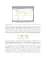
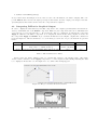
Upon starting Moses the desktop shown in figure 2 contains just a single window in which all elements in
the Basic repository are shown. The window is set up in two panes, tools on the left and all Moses objects
contained in the repository on the right. Initially only a folder containing configuration files config, tool
configurations Tools and a library Lib is contained in this repository . The library contains Components
and Formalisms with the Formalisms folder containing the 3 predefined component formalisms. It can also
be seen that the elements in the repository are hierarchically structured. This enables the user to separate
repository elements.
The Moses desktop also contains menu items that are useful in any context within the Moses environment.
Perhaps initially the most useful item is found under the Help menu. Here the online help system can be
accessed. This help is in HTML format and can be viewed either using the in-built help viewer or in any
external HTML web browser. Also of importance is the Exit menu entry found in the File menu. Currently
Moses does not check if everything has been stored in the repository. As a result the user must
take care to exit Moses only when all models have been checked into the repository.
In this tutorial you will create a number of models that help illustrate features of the Moses environment.
Upon completing this tutorial you will be able to independently model and simulate complex systems using
the predefined formalisms.
In Section 2, the tokenring network protocol is described, such that you will be able to understand how
to create your own model of a tokenring network interface card (in Section 3) and finally model a complete
tokenring network (in Section 4). In Section 5, you will learn more about the graph editor and its tools.
Figure 2: The Moses Tool started using the Demo repository
4
2
The Concept of IEEE 802.5 Token Ring
IEEE 802.5 Token Ring standard is based on the IBM Token Ring network. Token Ring has been used
mainly in large corporations in the 80’s and early 90’s, and was considered in the past to be the only way to
handle data communications in large networks (1000+ nodes).
Token Ring equipment is more expensive than Ethernet, and is one of the reasons that Ethernet is
more popular. The other reason is that Token Ring is a much more complex bus arbitration method than
CSMA/CD, and few network personnel understand the full capabilities of Token Ring.
2.1
IEEE 802.5 Bus Arbitration
Token Ring is a token-passing bus arbitration. A token is circulated on the ring. If a node on the ring needs
to access the ring (transfer information), it claims the token.
The token is a special packet that is circulated around the ring. It is read from one node, then passed to
the next node, until it arrives at a node that needs to access the ring (transfer information/data). When a
node receives the token, the node is allowed to send out its information packet.
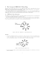
Figure 3: The basic configuration of a Token Ring network.
Example:
1. A token is circulating in the ring. Node B needs to send some data to Node G. Node B waits for the
token to arrive (there is only one token allowed on the ring). When it receives the token, it can then
send out its information packet. Node G is the destination address in this example.
Figure 4: Token and data leaving Node B.
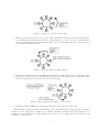
2. Node C receives the packet, reads the destination address, and passes it on to the next node. Node D,
E & F do likewise.
5
Figure 5: Passing on of the Token and data.
3. When the packet arrives at node G, node G reads the destination address and it reads the information.
Node G marks the information packet as read, and then passes it on. Note: the Source and Destination
addresses remain unchanged after passing through Node G. Node B is still the Source address and Node
G is still the Destination address.
Figure 6: Node G sending the marked Token.
4. The packet continues around the ring until it reaches the source address Node B. Node B checks to make
sure that the packet has been read (this indicates that Node G is actually present). The information
packet is erased and Node B releases the token onto the ring.
Figure 7: Token replaced and returned to the network.
5. Information marked READ is passed through the ring back to the Source (Node B).
The information packet is called the ”Token Frame.” The token itself is just called the ”Token” (sometimes
referred to as the ”Free Token”). This can be confusing. Remember, when we talk about a frame, we are
talking about data/information. When talking about a token, we are talking about bus arbitration and
permission to use the bus.
6
3
Building a Simple Network Interface
In this section you will build a model of a basic Token Ring interface using Moses. It will contain the
functions to accept an incoming Token, evaluate the Token, load and unload the bus with data, change
information contained in the Token and release the Token to the ring. Additionally, you will build a testing
environment, which you will use to check the proper functionality of your Token Ring interface.
3.1
Creating a Project Folder
Create a project folder TokenRingNIC in the repository.
3.2
Creating the Core Component
Create a new Moses component in your project folder TokenRingNIC using the TimePetriNet formalism.
Save the component in the repository using the name NIC.
Your basic Token Ring interface will contain the inputs Input and DataIn and the outputs Output and
DataOut for transferring Tokens and Data. The ports Input and Output are the connectors to the ring,
the ports DataIn and DataOut are the connectors from the local computer to the network card. Data to
be sent over the network is written by the computer to the input DataIn and is sent through the port
Output. Incoming data from the network arrives over port Input and will be passed to the computer over
port DataOut.
Create 5 places, 7 transitions and the 4 ports in the Graph Editor as shown in figure 8. You can create
a transition by clicking on the transition button in the editor and then clicking on the place you would like
to insert the new transition in your model. This procedure is described in Section 5.
Figure 8: The unconnected NIC
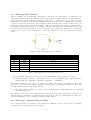
In a next step connect all the nodes in the way shown in figure 9.
Now the raw component is built and the only thing that is still to do is to add all parameters needed to
our component to fulfill correct functionality. In the following tables (see tables 3.2, 3.2, 3.2) all necessary
information is given. Make sure that you copy the given text correctly, this will minimize the probability of
errors. The numbers given in the table correspond to the numbers assigned to the nodes in figure 9.
Additionally you will have to set the attribute Parameters to ’address’. You can access this attribute
by clicking in the white space in the editor pane and open the attribute editor. You have to set this attribute
because we have to assign a value to the variable address that is used in the guard attributes.
7
Figure 9: The connected NIC
T-Nr.
1
Delay
0.01
2
0.04
3
4
0.01
0.01
5
6
7
0.02
0.02
0.02
Function
Guard
((data(0)<>0)
&&(data(1)<>address)
&&(data(2)<>address))
((data(1)=address)
&&(data(2)<>address))
data(0)=0
((data(0)<>0)
&&(data(2)=address))
Name
tokenOut=[0,0,0,currentTime()]
Table 2: The attributes for the transition nodes
Place-Nr.
1
2
3
4
5
InitialTokens
Name
RingIN
Trash
DataBuffer
TokenClass
Table 3: The attributes for the place nodes
After you have entered all necessary attributes, the component should look like the one in figure 10.
But let’s have a look at the functionality of the component. Please remember the previous chapter about
the Token Ring protocol (see chapter 2). Data or token packets arrive through the port Input to our card.
Then they are stored in a place with name RingIN. The Data/Token-packet is now ready to be processed
by the network card. The path through the network card the packet chooses depends on the data available.
The data format is given in table 5.
8
Node-Nr.
1
2
3
4
Name
Input
DataIn
Output
DataOut
Table 4: The attributes for the input/output nodes
Token Flag
Destination Address
Source Address
Sent Time
Table 5: Frame Format for Data/Token packets
As you can see in figure 10, there are four transitions that leave from place RingIN. They stand for four
different cases that may occur. According to the description of the token ring protocol, these four cases are:
1. The packet is a data packet (token flag = 1) that is neither from, nor for me.
2. The packet is a data packet with my address as destination address, but is not sent by me.
3. The packet is a token packet (token flag = 0).
4. The packet is a data packet that was initially sent by me. (Source address = my address)
In case 1 the packet has to be sent back to the ring, because we are not interested in this packet at all.
In case 2 we have to copy the data packet, send this copy to the output DataOut and send the initial packet
to the output Output, means back to the ring. If in case 3, where we receive a token packet, there is some
data waiting in place DataBuffer, we have to grab the token and send a data packet from this buffer to the
ring (Output ). Otherwise we just have to send the token back to the ring. In case 4, we are responsible
to remove the packet from the ring and send a new token packet to the ring. In the NIC component, this
is done by storing the data packet in the place Trash and creating a new token packet, that is sent to the
output Output.
These four cases in the component are modeled by the four transitions (marked 1-4 in figure 9). All of
these transitions would normally be activated, if a packet (also called token) is in place RingIN. To make
sure that only one transition may fire in time, so that the required task can be completed, we make use of
guards. A guard is a boolean expression, which has to be evaluated to true in order to enable the firing
of the transition it belongs to. In our card only one guard of the four transitions has the value true when a
packet is in place RingIN, so that only this transition can fire in the next step. In the next chapter you will
see how you can create a test environment to see if your network component works properly.
Now save the component to the repository by choosing File -> Save in the menu. You will be asked
to type in a name. Enter NIC and press Save. Now the component is stored in the repository. Choose
File -> Save and Exit to close the editors window. There should be a component NIC in the repository,
select it and press the compiler button. The component will be compiled. Close the Messages-Window by
clicking dismiss. The token ring network card is now ready to be simulated. What we need now is a testing
environment. Read the following chapter to create it.
3.3
Creating a Test Environment
To test the network card component, we need additional components, such as:
1. Source of ring packets
2. Source of data packets
3. Receiver of ring packets
4. Receiver of data packets
9
Figure 10: The NIC with all attributes set
Last but not least we need a component that connects these sources and receivers with the network card
component.
But let’s start by building a source of ring packets. Create a new Moses component in your working
directory. As formalism choose TimePetriNet. Add 1 place, 1 transition and 1 output port as shown
in figure 11. You have to set only a few attributes, you must specify a name for the output port , e. g.
srcout. Then you will have to assign a name to the edge arriving at the transition and the same name to
the edge leaving the transition. The most important parameter you will have to specify is the InitialTokensparameter. The value InitialTokens is actually a list of tokens, which are present at the beginning of a
simulation in a place. As an example look at the list [[0,0,0,0],[1,2,3,0]]. This is a list containing 2 elements.
The first one is a token [0,0,0,0] with token flag = 0. The second one is a data packet [1,2,3,0] with token
flag = 1, destination address = 2 and source address = 3. Save the component as TokenSrc and compile it.
Figure 11: A source of packets
Anologous to the source of ring packets, you will have to build a source of data packets. The only
difference between these two sources is the value of the InitialTokens-parameter at the place. A source of
data packets should not send tokens (packets with tokenflag = 0) to the network. Therefore an example of
the value InitialTokens would be [[1,2,1,0],[1,3,1,0]]. Be aware of the third part (source address) of the list
elements, which must be the same for all packets (here =1). Save the component as DataSrc and compile
it.
The receivers are even easier to build and are identical for data and ring packets. The receiver component
is also a TimePetriNet component, which consists only of a input port and a place. The only attribute
that has to be set is the name of the input port (sinkin). See figure 12. Save the component as DataSink
and compile it.
Now the only component that still has to be built is the one connecting the senders, receivers and the
network card component. Create a new Moses component in your working directory in the repository (
TokenRingNIC). As formalism choose ProcessNetwork. This new component will serve as a testbed
for the core component. Add 5 process nodes to the component as shown in figure 13. In these process
nodes Moses components (such as TimePetriNet components, ProcessNetwork or java components) can be
10
Figure 12: A sink of packets
PN-Nr.
1
2
3
4
5
InputPorts
[“Input”,”DataIn”]
[“sinkin”]
[“sinkin”]
OutputPorts
[“srcout”]
[“srcout”]
[“Output”,”DataOut”]
Constructor
new TokenSrc()
new DataSrc()
new NIC(map [“address”->1])
new DataSink()
new DataSink()
Table 6: Attributes of process nodes
instantiated. That’s what will be done here. We instantiate a TokenSrc component in process node 1, a
DataSrc component in process node 2, in process node 3 a NIC, in 4 and 5 a DataSink. To do like this,
set the attributes as given in table 6.
Figure 13: The testbed for the network card
Please be aware of using the same names for InputPorts as you have used for the names of the input
ports in the referenced components. Otherwise you will fail on simulating the components. After having set
the attributes, you can connect the process nodes as shown in figure 13. Save the component as testbed
and compile it. Now you have created all components needed to test the network interface card and you can
proceed to the next chapter.
3.4
Testing and Animating the Core Component
In this chapter you will be guided to test the network card. If you look at the directory TokenRingNIC
there should be the components NIC, TokenSrc, DataSrc, DataSink and testbed. All of these components
should have been compiled. If you didn’t compile them yet, you should do this now by selecting them and
pressing the Compiler button.
11
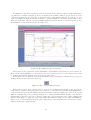
To simulate a component, you have to select it and click on the Animator button. In the first window
you just have to click the OK button. Now you should see the animator window. If you click now on the
component shown in the tree view part on the left had side of the animator window, you can choose open
animation (within the right mouse button menu) to open the simulated component. In the newly opened
window you can click on the process nodes with the right mouse button and choose toggle transparency. Now
the instantiated components are shown. (see figure 14 )
Figure 14: The animated testbed component
In the places of the components on the left hand side of the animated component you can see black dots.
These are the tokens initially set to these places. You can open these places, to see the values of the tokens
by clicking them with the right mouse button and choosing inspect.
To check the correct behaviour of the network interface card, you will have to animate it step by step by
clicking on the one step button (see figure 15).
Figure 15: The one step animation button
Every time you click on the one step button, one step of the animation is performed. Now check if the
component processes the data packets in a correct way. If, e.g., the data packet arriving at the RingIN place
of the network card is a token (token flag =0) then it should be passed by transition 3 to place 4. To test all
different cases that may occur, you will probably have to change the InitialTokens attribute of the DataSrc
and TokenSrc component. You can do this by opening the components in the editor. After changing and
saving you will have to compile the components again. Otherwise the changes do not affect the animation.
After you are convinced that the network card component processes all packets in a correct way you have
finished the first part of this tutorial.
12
4
Assembling and Simulating a Whole Network
In this chapter you will now use your network card component to build a “real” Token Ring network with four
nodes. You will then be able to simulate and evaluate this network. In the following sections all components
needed for the simulation of the network will be introduced. First you will learn how a packet counter can be
implemented within your existing network card. This counter will be used to analyse the buffer fill levels of
the NICs. In a next section all the components needed for graphical output are described. These components
will allow you to inspect buffer fill levels and packet travelling time graphically. In Section 4.3 we describe,
how you can set up data packet sources in order to generate load for your test network. Finally, in Sections
4.4, 4.5 and 4.6, you will build the network, simulate it and try to tune the network parameters, such that
the network is balanced.
4.1
Preparing a Network Node for Simulation Output
To have the possibility to inspect several parameters of the whole network, you will have to add some small
changes to your network card component. Additionally, there are two parameters that are interesting to
display:
• Queue length in each network card
• Packet delay time (i.e. the time between arrival at the DataBuffer in a network card and removal from
the ring.
To have access to these parameters you will have to add changes to the component NIC. First of all
you need a counter in the NIC, that writes the number of packets waiting in DataBuffer to a output
QueueLengthOut every time the queue length changes. In figure 16 you can see an idea of such a counter.
Add such a counter, that gives out the number of tokens waiting in DataBuffer, to your NIC component.
Figure 16: Counter for Queue Length
To have access to the packet delay time, you will have to make some changes in the path of the NIC, where
packets with source address = address are processed. (in transition 4) Instead of collecting the removed
packets in place Trash, you have to send the packets to a new output OwnPacketOut. Add a new output
named OwnPacketOut and add an edge with name outData from transition 4 to this new output. You can
delete the place named Trash. Because you are only interested in the delay time and not in other parameters
of the packet (such as token flag, destination and source address), you will have to change the value of the
tokens to the effective delay time. As you know at the fourth element of a token, the sent time is stored.
This allows you to calculate the delay time for the packet. Change the function of transition 4 to:
13
• outData=currentTime()-data(3)
Now you have made all changes needed to have access to the information you want to display. The component NIC should now have the input ports Input and DataIn, and the output ports Output, DataOut,
QueueLengthOut and OwnPacketOut. Save the component and compile it.
4.2
Integrating PtPlot for Graphical Output
In order to display the data written by the NIC component to the outputs QueueLengthOut and OwnPacketOut, you will make use of the PtPlot component. That is a java component, that can be instantiated in
a process node of a process network, too. To prepare the data to be displayed, we will use the component
Apply in addition to the PtPlot component. So, to display the data from the debug outputs, we need both
the components Apply and PtPlot. A process network with the needed inputs, outputs and constructors
is given in figure 17. All the attributes to be set in these process nodes of a process network are given in
table 7.
PN-Name
PtPlot
Apply
Constructor
new moses.basic.PtPlot(
map [“title” -> “Window title”])
new moses.basic.Apply(lambda(x)[“Label”,x] end)
InputPorts
OutputPorts
[“Data”,”Redraw”]
[“A”]
[“B”]
Table 7: The Parameters for PtPlot
Please replace the string “Window title” by a string that applies to the displayed date. The string
“Label” in the constructor of the Apply-component, too, can be replaced with a string matching the data
to be displayed. Please take a look at figure 18 to see, where these strings appear.
Figure 17: The process network used for PtPlot
Figure 18: The meaning of “Window title” and “Label”
14
4.3
Setting up Data Sources
Instead of making use of the TokenSrc and DataSrc component of the last chapter, you will have to use
a new data packets source, that randomly generates data packets and writes them to the input DataIn of
your network card. Now you will create this data packet source. To do this, create a new Moses component
named Generator using the TimePetriNet formalism. As next step, add a place, a transition and an output
to the new component. Connect the parts as shown in figure 19. In the place on the left, there will be one
initial token, which always activates the transition. The delay specified in the transition determines after
how many time ticks after activation, the transition may fire. In the function of the transition we specify
the format of the token that is written out to the output-port as specified in an earlier section. For the data
packet source to work correctly you will have to enter a few parameters to the component. Please check in
table 8.
Figure 19: The Data Packet Source component
Part
General
General
Place
Place
Transition
Transition
Output
Attribute
Parameters
Name
Name
InitialTokens
Function
Delay
Name
Value
address, rand, numberOfNodes, minDelay, maxDelay
Generator
Pool
[null]
output = [ 1, (rand’nextInt(numberOfNodes)) ,address,currentTime()]
[”interval”, minDelay, maxDelay]
Output
Table 8: The Parameters for the Data Packet Source
The following line shows how the constructor for the Generator component has to be called:
• new Generator(map [”address”-> ownAddress, ”rand” -> new java.util.Random(), ”numberOfNodes”> numberOfNodes, ”maxDelay”->maxDelay, ”minDelay”− >minDelay])
The variables ownAddress, etc. have to be replaced by values. For example a source that produces data
packets for a network card with address 2 within a network with 4 computers and transmits a packet every
5-10 time units will have the following constructor:
• new Generator(map [”address”->2, ”rand”->new java.util.Random(), ”numberOfNodes”->4, ”maxDelay”>10, ”minDelay”->5])
The variable rand is used to hold a random number generator, which generates destination addresses randomly from 0 up to the number of computers in the network. A process node containing such a packet source
component must have only one output port which is named Output.
4.4
Setting up a Network of Four Nodes
Now you have knowledge about all the components that you will have to use to create a network containing
four network card components with data collection:
15
• NIC component, network card with two additional data collection outputs
• component Generator, variable data source
• Apply & PtPlot, graphical analysis components
Create a component Network using the ProcessNetwork formalism. Design a network containing four
NICs, a display for the queue length of each network card and a display for the delay times of all packets.
The only thing that is missing now is the first token on the ring. Without a token on the ring no network
card could ever send data to the ring. So you will have to create a first token and send it somewhere to the
ring. To achieve this you can make use of the TokenSrc component of the previous chapter. You will have
to set the attribute InitialTokens of the place to [[0,0,0,0]], save the component and compile it.
After you have designed the network, save the component and compile it.
4.5
Testing and Animating the Token Ring Network
To animate the network, select the test component and click on the Animator button. If you have created
a correct network then the animator should be shown with multiple diagram windows. Otherwise an error
message will be displayed and you will have to look for the error you have made. If an error occurs, check the
spelling of the input and output ports of your components and the spelling and parameters of the components
in the constructors.
If everything is fine, enter in the simulation tool that it should stop after 20000 events. Set the simulation
speed to fast and click on the start button. If you look at the diagrams you obtained after the simulation
has stopped, you can see if the network is fast enough to process all the packets that are sent to the network.
4.6
Variation of Simulation Parameters and Interpretation
Now try to change the parameters of the network such as delays in the network interface cards and the
parameters of the data sources. To apply all changes you will have to save and recompile all changed
components. Try to find parameters in which the network is overloaded, which means that the queue lengths
of the NICs tend to infinity. Find parameters in which the network is not fully loaded, which means that all
queue lengths are more or less always 1 or 0. Finally, try to find parameters in which the network is loaded
in a way that there is always a packet sent over the ring, but the queue lengths are not tending to infinity.
16
5
The Graph Editor Commands
Like almost all tool components in Moses the Graph editor is very configurable. The Graph editor assumes
that all graphics information has been defined in the formalism GT DL description. A typical description
defines the vertices and edges of a formalism including their graphical representation. This can be considered
to define the syntax alphabet of a formalism. In addition predicates can be declared in the GT DL file that
describe the syntax rules. These predicates are executed during the editing process or explicitly via a menu
or tool bar item.
This appendix describes the components and tools of the Graph editor. More detailed information is
available in the Moses user manual which also includes information on how the editor menu and tool bar
entries can be configured. In this tutorial a brief description will be given sufficient to create the model.
Figure 20: The Graph editor tool bar for Time Petri Net components. From left to right: (Check in, Print,
Open/Close Graph Editor Pane, Open/Close Attribute Editor, Move up a model hierarchy, Move down into a
model hierarchy, Check Syntax, Cut, Copy, Paste, Selection mode, Insert Comment mode, Insert arc mode,
Insert inhibitor arc mode, Insert place mode, Insert transition mode, Insert container place mode, Insert
input connector mode, Insert output connector mode)
5.1
The Tool Bar
Associated with the T imeP etriN et formalism is a properties file that describes the editor tool bar. Figure 20
shows the tool bar. The following list names and describes each icon in sequence from left to right.
Save Save the component into the repository. This command overwrites the previously saved component;
Print Print the currently displayed model;
Open/Close additional Graph Editor Pane The second editor pane is used in situations where two
different portions of the same model are to be viewed simultaneously at perhaps different magnifications;
Open/Close Attribute Editor The component itself and each vertex and edge may have attributes.
These attributes are defined in the GT DL file and are edited in the attribute editor;
Move up a model hierarchy For formalisms that contain hierarchy such as Harel’s Statecharts this button will move the currently visible editable model to the next highest in the model hierarchy;
Move down into a model hierarchy If the currently selected vertex contains hierarchical sub-components then the current editable model can be changed to one of the sub-components. If a vertex
contains more than one sub-component then a pop–up menu allows the desired component to be
chosen;
Check Syntax This tool bar item will cause the current component to be syntax checked and if errors
are found an error window will appear. The color of the button indicates whether the current graph
contains syntax errors (red ⇒ error, green ⇒ OK);
Cut Cut the current selection from the component;
Copy Copy the current selection;
Paste Paste the previously cut or copied selection into the component. The newly inserted elements will
be selected;
Selection mode Set the editor mode so that component elements can be selected and manipulated;
17
Insert Comment mode In this mode when the mouse enters the edit pane a comment will be shown
to float within the component. The component can be inserted by clicking the mouse at the desired
position;
Insert arc mode In this mode when the mouse enters the edit pane an arc will be shown to float within
the component. The source of the arc is defined by clicking the mouse on the desired vertex while
the destination is defined by clicking a second time on the destination vertex. If between defining the
source vertex the user clicks at a position where no vertices are present a knick point will be inserted;
Insert inhibitor arc mode As above but instead of an arc an inhibitor arc will be used;
Insert place mode A place element can be inserted when the editor is in this mode;
Insert transition mode A transition element can be inserted when the editor is in this mode;
Insert container place mode A container place element can be inserted when the editor is in this mode;
Insert input connector mode An input connector element can be inserted when the editor is in this
mode;
Insert output connector mode An output connector element can be inserted when the editor is in this
mode.
5.2
The Menu Bar
The following lists describe the Graph editor menus. As T imeP etriN et is not a formalism that requires
hierarchical components the Hierarchy menu will be ignored.
Figure 21: The Graph editor Graph menu
Figure 21 shows the Graph menu. The following list describes the graph editor Graph menu entries.
Save Save the component into the repository. This command overwrites the previously saved component;
Save as Save the component into the repository under a different name;
Check Syntax This tool bar item will cause the current component to be syntax checked and if errors are
found an error window will appear;
Open/Close Graph Editor Pane The second editor pane is used in situations where two different portions of the same model are to be viewed simultaneously at perhaps different magnifications;
Open/Close Attribute Editor The component itself and each vertex and edge may have attributes.
These attributes are defined in the GT DL file and are edited in the attribute editor;
Save as GIF The component is saved as GIF file for your documantation.
18
Printer Setup... On some platforms this menu entry will cause a system dialog to appear where printer
parameters can be viewed and modified;
Print Print the currently displayed model;
Quit Close the editor discarding any changes made to the component since the last check in;
Save and Exit Close the editor after the component has been saved.
Figure 22: The Graph editor Edit menu
Figure 22 shows the Edit menu. The following list describes some of the graph editor Edit menu entries.
Undo Most editor operations can be undone by selecting this menu entry;
Redo Previously undone operations may be redone by selecting this menu entry;
Cut Cut the current selection from the component;
Copy Copy the current selection;
Paste Pastes the previously cut or copied selection into the component. The newly inserted elements will
be selected;
Select All Selects all vertices and edges in the current component;
Select None Ensures that no component elements are selected;
Layout Graph Gives a shot at arranging your graph;
Flip Contains a sub menu with menu items to flips the current selection about the vertical and horizontal
axes;
Rotate Contains a sub menu with menu items to rotate the current selection;
Align Contains a sub menu with menu items to reposition a number of elements with respect to the first
selected element.
Figure 23 shows the Insert menu. The following list describes some of the graph editor Insert menu
entries.
Comment In this mode when the mouse enters the edit pane a comment will be shown to float within the
component. The component can be inserted by clicking the mouse at the desired position;
Arc In this mode when the mouse enters the edit pane an arc will be shown to float within the component.
The source of the arc is defined by clicking the mouse on the desired vertex while the destination is
defined by clicking a second time on the destination vertex. If between defining the source vertex the
user clicks at a position where no vertices are present a knick point will be inserted;
19
Figure 23: The Graph editor Insert menu
Inhibitor Arc As above but instead of an arc an inhibitor arc will be used;
Place A place element can be inserted when the editor is in this mode;
Transition A transition element can be inserted when the editor is in this mode;
Container Place A container place element can be inserted when the editor is in this mode;
Input Connector An input connector element can be inserted when the editor is in this mode;
Output Connector An output connector element can be inserted when the editor is in this mode.
20
6
Conclusion
The goal of this tutorial was to help you in modeling a system using the Moses tool. You were shown how
to model different parts of the system using different formalisms and how to combine them into a consistent
model. Furthermore, you have learned to simulate and evaluate a model.
The skills you have acquired will hopefully motivate you into modeling more realistic systems. Moses also
comes with a repository containing a number of demonstration models. As a next step it would be useful
to study these examples as they all highlight particular aspects of Moses that may not have been touched
upon by the tutorial. Finally the Moses reference manual contains information about how to configure and
extend Moses.
We hope you have enjoyed the tutorial and that it has left you motivated to continue using Moses.
Jan Beutel and Simon Künzli, November 2003
21