1
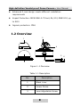
High-definition Vandal-proof Dome Camera User Manual UD.6L0201D0109A01 High-definition Vandal-proof Dome Camera· User Manual Thank you for purchasing our product. If there are any questions, or requests, please do not hesitate to contact the dealer. This manual applies to Model Model DS-2CC5181P(N)-VPIR(H) DS-2CC5191P(N)-VPIR(H) DS-2CC5195P(N)-VPIR(H) DS-2CC5197P(N)-VPIR(H) DS-2CC51A1P(N)-VPIR(H) DS-2CC51A5P(N)-VPIR(H) DS-2CC51A7P(N)-VPIR(H) This manual may contain several technical incorrect places or printing errors, and the content is subject to change without notice. The updates will be added to the new version of this manual. We will readily improve or update the products or procedures described in the manual. DISCLAIMER STATEMENT “Underwriters Laboratories Inc. (“UL”) has not tested the performance or reliability of the security or signaling aspects of this product. UL has only tested for fire, shock or casualty hazards as outlined in UL’s Standard(s) for Safety, UL60950-1. UL Certification does not cover the performance or reliability of the security or signaling aspects of this product. UL MAKES NO REPRESENTATIONS, WARRANTIES OR CERTIFICATIONS WHATSOEVER REGARDING THE PERFORMANCE OR RELIABILITY OF ANY SECURITY OR SIGNALING RELATED FUNCTIONS OF THIS PRODUCT.” 1 High-definition Vandal-proof Dome Camera· User Manual Regulatory Information FCC Information FCC compliance: This equipment has been tested and found to comply with the limits for a digital device, pursuant to part 15 of the FCC Rules. These limits are designed to provide reasonable protection against harmful interference when the equipment is operated in a commercial environment. This equipment generates, uses, and can radiate radio frequency energy and, if not installed and used in accordance with the instruction manual, may cause harmful interference to radio communications. Operation of this equipment in a residential area is likely to cause harmful interference in which case the user will be required to correct the interference at his own expense. FCC Conditions This device complies w ith part 15 of the FCC Rules. Operation is subject to the following two conditions: 1. This device may not cause harmful interference. 2. This device must accept any interference received, including interference that may cause undesired operation EU Conformity Statement This product and - if applicable - the supplied accessories too are marked with "CE" and comply therefore with the applicable harmonized European standards listed under the Low Voltage Directive 2006/95/EC, the EMC Directive 2004/108/EC. 0100001021227 2 High-definition Vandal-proof Dome Camera· User Manual 2002/96/EC (WEEE directive): Products marked with this symbol cannot be disposed of as unsorted municipal waste in the European Union. For proper recycling, return this product to your local supplier upon the purchase of equivalent new equipment, or dispose of it at designated collection points. For more information see: www.recyclethis.info. 2006/66/EC (battery directive): This product contains a battery that cannot be disposed of as unsorted municipal waste in the European Union. See the product documentation for specific battery information. The battery is marked w ith this symbol, which may include lettering to indicate cadmium (Cd), lead (Pb), or mercury (Hg). For proper recycling, return the battery to your supplier or to a designated collection point. For more information see: www.recyclethis.info. 3 High-definition Vandal-proof Dome Camera· User Manual Table of Contents 1 Introduction ........................................................................6 1.1 Product Features ...................................................... 6 1.2 Overview ................................................................. 8 2 Installation........................................................................10 2.1 Ceiling Mounting .................................................... 10 2.2 In-ceiling Mounting ................................................ 14 2.3 In-ceiling Mounting w ith gang box .......................... 17 2.4 Indoor Wall Mounting ............................................. 19 2.5 Image and Focus Adjusting .................................... 22 2.6 Wiring .................................................................... 24 3 Menu Description ..............................................................25 3.1 Menu Description (A).............................................. 25 3.1.1 Menu Overview ............................................. 25 3.1.2 Lens Settings ................................................ 26 3.1.3 Shutter/AGC Setting ..................................... 28 3.1.4 White Balance Setting ................................... 30 3.1.5 Backlight Compesation Setting ...................... 33 3.1.6 Picture Adjust Setting.................................... 33 3.1.7 ATR Setting ................................................... 34 3.1.8 Motion Detection Setting ............................... 35 3.1.9 Privacy Mask Setting ..................................... 37 3.1.10 Day/Night Setting ....................................... 38 3.1.11 NR Setting .................................................. 41 3.1.12 Camera ID Setting ...................................... 41 3.1.13 SYNC Setting .............................................. 43 3.1.14 Language Setting ........................................ 44 3.1.15 Camera Reset Setting.................................. 44 4 High-definition Vandal-proof Dome Camera· User Manual 3.1.16 Defective Pixel Correct Settings ................... 44 3.1.17 Save All/Exit ............................................... 45 3.2 Menu Description (B).............................................. 46 3.2.1 Scene ........................................................... 47 3.2.2 Exposure....................................................... 47 3.2.3 Funtion ......................................................... 55 3.2.4 System ......................................................... 63 3.2.5 Language ...................................................... 65 3.2.6 Exit ............................................................... 66 5 High-definition Vandal-proof Dome Camera· User Manual 1 Introduction 1.1 Product Features This series of camera adopts high performance sensor and advanced circuit board design technology. It features high resolution, low distortion, and low noise, etc. It is suitable for the surveillance system and image process system. The main features of DS-2CC5181P (N)-VPIR (H), DS-2CC5191P (N)-VPIR (H), and DS-2CC51A1P (N)-VPIR (H) are as fo llows: High performance SONY CCD and high resolution bring high-quality image Low illumination, 0.001 Lux @ (F1.2, AGC ON), 0 Lux w ith IR Support ICR filter auto switch OSD menu, parameters are configurable. Support auto white balance with high color rendition High Signal No ise Ratio (SNR), which brings clear and high-quality image SMART IR Auto iris Up to 8 configurable privacy masks to ensure your privacy Advanced 3-axis design meets different installation requirements 6 High-definition Vandal-proof Dome Camera· User Manual Impact Protection: IEC60068-2-75 test, Eh, 50J; EN50102, up to IK10 Ingress protection: IP66 The main features of DS-2CC5195P (N)-VPIR (H), DS-2CC5197P (N)-VPIR (H), DS-2CC51A5P (N)-VPIR (H), and DS-2CC51A7P (N)-VPIR (H) are as follows: High performance SONY CCD and high resolution bring high-quality image Low illumination, 0.001 Lux @ (F1.2, AGC ON), 0.0001 Lux @ (F1.2, AGC ON, sensitivity × 512), 0 Lux with IR Support ICR filter auto switch OSD menu, parameters are configurable Wide Dynamic Range (supported by DS-2CC5197P (N)-VPIR(H) and DS-2CC51A7P(N)-VPIR(H)) for backlighting surveillance Back Light Compensation (BLC) with programmable BLC area Support auto white balance with high color rendition High Signal No ise Ratio (SNR) brings clear and high-quality image SMART IR Electronic image stabilization (EIS) function to get steady and clear image Eclipse Auto iris Privacy mask with 8 optional co lors and 12 configurable areas 7 High-definition Vandal-proof Dome Camera· User Manual Advanced 3-axis design meets different installation requirements Impact Protection: IEC60068-2-75 test, Eh, 50J; EN50102, up to IK10 Ingress protection: IP66 1.2 Overview 3 1 4 5 2 Figure 1-1 Overview Table 1-1 Description No. Description 1 Black Liner 2 Lower Dome 3 Lens Adjustable Screw 8 6 High-definition Vandal-proof Dome Camera· User Manual No. Description 4 Tilting Screw 5 Power Cable 6 Video Cable 9 High-definition Vandal-proof Dome Camera· User Manual 2 Installation Before you start: Please make sure that the device in the package is in good condition and all the assembly parts are included. Make sure that all the related equipment is power-off during the installation. Check the specification of the products fo r the installation environment. Check whether the power supply is matched w ith your AC outlet to avoid damage. If the product does not function properly, please contact your dealer or the nearest service center. Do not disassemble the camera for repair or maintenance by yourself. Please make sure the wall is strong enough to withstand three times the weight of the camera and the mounting. 2.1 Ceiling Mounting Steps: 1. Attach the drill template (supplied) to the place where you want to fix the camera. 2. Drill the screw hole and the cable hole in the ceiling according to the drill template. 10 High-definition Vandal-proof Dome Camera· User Manual Wall Drill Template Figure 2-1 Drill Template 3. Loosen the three screws on the edge of the low er dome with the supplied screwdriver. 4. Remove the lower dome and the black liner. Screws Figure 2-2 Remove the Lower Dome 11 High-definition Vandal-proof Dome Camera· User Manual 5. Loosen the three set screws as shown in Figure 2-3 with the supplied screwdriver. 6. Remove the camera from the back box. Back Box Set Screws Figure 2-3 Remove the Camera 7. Attach the back box to the ceiling by aligning the holes of the back box with the holes on the drill template. 8. Secure the back box with the supplied screws. 12 High-definition Vandal-proof Dome Camera· User Manual Cable Ho le Figure 2-4 Secure the Back box 9. Route the cables through the cable hole. 10. Align the camera with the back box. 11. Tighten the set screws to secure the camera with the back box. 12. Connect the video output connector to the monitor. Connect the power connector to the power supply. 13. Adjust the image and focus. Please refer to the section 2.5 for more details. 14. Fit the black liner back to the camera. 15. Tighten the screws to secure the lower dome with the back box. 13 High-definition Vandal-proof Dome Camera· User Manual Figure 2-5 Secure Lower Dome 2.2 In-ceiling Mounting Steps: 1. Attach the drill template (supplied) to the place where you want to fix the camera. 2. Drill the screws ho le and the cable hole in the ceiling according to the drill template. 14 High-definition Vandal-proof Dome Camera· User Manual Ceiling Drill Template Figure 2-6 The Drill Template 3. Fold the toggle to get the toggle bo lt go through the screw holes of the in-ceiling mount. 4. Keep screwing the bolt till the toggle unfolds and props on the ceiling. Bolt Toggle In-ceiling Mount Figure 2-7 The In-ceiling Mount 15 High-definition Vandal-proof Dome Camera· User Manual 5. Route the cables through the hole in the center of the in-ceiling mount. 6. Align the camera with the in-ceiling mount. 7. Tighten the set screws to secure the camera with the in-ceiling mount. 8. Connect the video output connector to the monitor. Connect the power connector to the power supply. 9. Adjust the image and focus. Please refer to the section 2.5 for more detailed information. Figure 2-8 Secure the Camera 10. Fit the black liner back to the camera. 11. Align the lower dome with the in-ceiling mount. 12. Tighten the screws to secure the lower dome with the in-ceiling mount. 16 High-definition Vandal-proof Dome Camera· User Manual Figure 2-9 Secure the Lower Dome 2.3 In-ceiling Mounting with gang box Steps: 1. Secure the In-ceiling mount (supplied) to the gang box with two screws. Ceiling Gang Box In-ceiling Mount Figure 2-10 In-ceiling Mount 17 High-definition Vandal-proof Dome Camera· User Manual 2. Route the cables through the hole in the center of the in-ceiling mount. 3. Align the camera with the gang box. 4. Tighten the screws to secure the camera with the gang box. 5. Connect the video output connector to the monitor. Connect the power connector to the power supply. 6. Adjust the image and focus. Please refer to the section 2.5 for more details. Gang Box Ceiling Camera Figure 2-11 Secure the Camera 7. Fit the black liner back to the camera. 8. Align the lower dome with the in-ceiling mount. 9. Tighten the screws to secure the lower dome with the in-ceiling mount. 18 High-definition Vandal-proof Dome Camera· User Manual Figure 2-12 Secure the Lower Dome 2.4 Indoor Wall Mounting Steps: 1. Disassemble the lower dome, black liner and the camera as you do in chapter 2.1. 2. Align the number 2 holes of the back box with the number 1 holes of the wall mount. 3. Secure the back box to the wall mount with four screws. 19 High-definition Vandal-proof Dome Camera· User Manual Figure 2-13 Secure the Back Box 4. Route the cables through the ho le in the center of the wall mount. 5. Align the camera with the back box. 6. Tighten the set screws to secure the camera with the back box. 7. Connect the video output connector to the monitor. Connect the power connector to the power supply. 8. Adjust the image and focus. Please refer to the section 2.5 for more detailed information. 20 High-definition Vandal-proof Dome Camera· User Manual Figure 2-14 Secure the Camera 9. Fit the black liner back to the camera. 10. Align the lower dome with the camera. 11. Tighten the screws to secure the lower dome with the camera. Figure 2-15 Secure the Lower Dome 21 High-definition Vandal-proof Dome Camera· User Manual 2.5 Image and Focus Adjusting Steps: 1. Three-axis adjustment. 1). View the camera image using the monitor. 2). Rotate the panning table to adjust the panning position of the camera. 3). Loosen the tilting lock screw. 4). Rotate the tilting table to adjust the tilting position of the camera. 5). Tighten the tilting lock screw. 6). Rotate the lens to adjust the azimuth angle of the image. Pan Rotation Tilt Tilting Lock Screw Figure 2-16 Three-axis Adjustment 22 High-definition Vandal-proof Dome Camera· User Manual 2. Zoom and focus adjustment. 1). View the camera image using the monitor. 2). Loosen the zoom lock screw and move the screw between T (Tele) and W (Wide) to obtain the appropriate angle of view. 3). Tighten the zoom lock screw. 4). Loosen the focus lock screw and move the screw between F (Far) and N (Near) to obtain the optimum focus. 5). Tighten the focus lock screw. Zoom Lock Screw Tilting Lock Screw Focus Lock Screw Aux Video Menu Output Button Connector Figure 2-17 Lens Adjustment 23 High-definition Vandal-proof Dome Camera· User Manual 2.6 Wiring Figure 2-18 The Power/Video Cable (Two-pins Power Interface) Notes: Please make sure that the power adapter can match with the camera. The standard power supply of the camera is 12V DC or 24V AC (Please refer to technical specifications for more details). 24 High-definition Vandal-proof Dome Camera· User Manual 3 Menu Description 3.1 Menu Description (A) Note: The menu described in this chapter is applicable to DS-2CC5181P (N)-VPIR (H), DS-2CC5191P (N)-VPIR (H), and DS-2CC51A1P (N)-VPIR (H). 3.1.1 Menu Overview This series of camera supports OSD menu operation, and the menu is listed below: LENS AUTO, MANUAL SHUTTER/ SHUT+AUTO IRIS, AUTO IRIS, SHUT+AGC,SHUT AGC Main Menu WHITE BAL ATW, PUSH, PUSH LOCK, USER1, USER2, ANTI CR, MANUAL BACKLIGHT BLC,HLC PICT ADJUST MIRROR, BRIGHTNESS, CONTRAST, SHARPNESS, HUE, GAIN ATR LUMINANCE, CONTRAST MOTION DET DETECT SENSE, BLOCK DISP, MONITOR AREA, AREA SEL 25 High-definition Vandal-proof Dome Camera· User Manual PRIVACY AREA SEL, COLOR, TRANSP, MOSAIC DAY/NIGHT AUTO, COLOR, B/W, EXT1/EXT2 NR Y LEVEL CAMERA ID SYNC INT , LINELOCK LANGUAGE English/Chinese/Japanese/ French/Russian/ Portuguese/ Spanish/ German CAMERA RESET DPC EXIT/SAVE ALL Note: This series of camera adopts joystick control. You can select the menu item by setting the joystick, which is beside the lens, to up/down/left/right. 3.1.2 Lens Settings Move the cursor to LENS, and set the menu button left/right to select MANUAL or AUTO. Selecting MANUAL mode, the iris is set at the maximum value, and it is not configurable. 26 High-definition Vandal-proof Dome Camera· User Manual Selecting AUTO mode, press the menu button to enter the AUTO IRIS submenu. AUTO IRIS TYPE MODE SPEED DC AUTO ---|-----080 RETURN Figure 3-1 AUTO IRIS AUTO IRIS can automatically adjust the iris according to the changing light conditions. TYPE: It supports Direct Current Driven (DC). There is a drive circuit in the camera which can directly output DC control voltage to control electronic motor. MODE: AUTO, OPEN, and CLOSE are selectable for iris mode. AUTO: The iris adjusts automatically according to the changing light environment; OPEN: The iris is fully open; CLOSE: The iris is totally closed. SPEED: Adjust the iris speed. The higher the value is, the faster the speed of the auto iris is. The value ranges from 0 to 255. Note: It is recommended that you adjust the iris speed only when the iris vibrates. 27 High-definition Vandal-proof Dome Camera· User Manual 3.1.3 Shutter/AGC Setting SHUTTER/AGC allows you to adjust the image brightness in different light conditions. MANUAL or AUTO mode is selectable for the shutter and AGC. AUTO Mode: HIGH LUMINANCE Move the cursor to Mode in HIGH LUMINANCE, and select SHUT+AUTO IRIS or AUTO IRIS. SHUT+AUTO IRIS means adjust the image brightness via shutter and iris. AUTO IRIS means adjust the image brightness via iris. Move the cursor to BRIGHTNESS in HIGH LUMINANCE, and select the value to adjust the brightness. Note: High luminance means the environmental illumination is quite high, and the image brightness is controlled by the shutter and the iris. If you set the lens as Manual in the Lens Settings interface, only Shutter is available for Mode, which means the image brightness is controlled via shutter. The value ranges from 0 to 255. LOW LUMINANCE Move the cursor to Mode in LOW LUMINANCE. Only AGC is available, which means the image brightness is adjusted by AGC. Move the cursor to Brightness in LOW LUMINANCE, and adjust the AGC value to control the image brightness. ×1.00, ×0.75, × 0.50 and ×0.25 are selectable 28 High-definition Vandal-proof Dome Camera· User Manual Note: Low Luminance means the environmental illumination is low, and you can use the AGC to brighten the image. AUTO SETUP HIGH LUMINANCE MODE SHUT+AUTO IRIS/AUTO IRIS BRIGHTNESS ----|---- 080 LOW LUMINANCE MODE BRIGHTNESS AGC ×0.50 RETURN Figure 3-2 AUTO SETUP Manual Mode: Move the cursor to Mode in Manual, SHUT+AGC is selectable. You can adjust the image brightness by shutter and AGC. MANUAL SETUP MODE SHUTTER AGC SHUT+AGC 1/50 6.00 RETURN Figure 3-3 MANUAL SETUP 29 High-definition Vandal-proof Dome Camera· User Manual Shutter: 1/50, 1/120, 1/250, 1/500, 1/1k, 1/2k, 1/4k, and 1/10k are selectable for PAL standard. 1/60, 1/100, 1/250, 1/500, 1/1k, 1/4k, and 1/10k are selectable for NTSC standard. AGC: 6.00, 12.00, 18.00, 24.00, 30.00, 36.00, 42.00, and 44.80 are selectable for the AGC value. 3.1.4 White Balance Setting Move the cursor to the White Balance, and select ATW, PUSH, PUSH LOCK, USER1, USER2, ANTI CR and MANUAL by setting the menu button to left/right. ATW(Auto Tracking White Balance) In ATW mode, white balance is continuously being adjusted in real-time according to the color temperature of the scene illumination. SPEED The speed can be set from 0 to 255. DELAY CNT It is the response time when the color temperature changes. ATW FRAME It is used to adjust the image size of the ATW image. ENVIRONMENT INDOOR and OUTDOOR are selectable. 30 High-definition Vandal-proof Dome Camera· User Manual ATW SPEED DELAY CNT ATW FRAME ENVIRONMENT ------|--239 --|------016 ×1.00 INDOOR RETURN Figure 3-4 ATW USER 1/USER2 USER 1 is the indoor mode and it is suitable for the indoor environment. B-Gain and R-Gain are adjustable. USER 2 is suitable for the fluorescent light environment. B-Gain and R-Gain are adjustable. USER 1 WB B-GAIN R-GAIN ---|-----030 ---|-----033 RETURN Figure 3-5 USER 1 WB 31 High-definition Vandal-proof Dome Camera· User Manual MANUAL Selecting MANUAL and pressing the menu button to enter the MANUAL WB submenu. Customize the LEVEL value which is 0 to 255 selectable on your demand. MANUAL WB LEVEL ----|----064 RETURN Figure 3-6 MANUAL WB PUSH In the PUSH mode, the viewed image retains color balance automatically. The color in the image balances according to the color temperature. PUSH LOCK In the PUSH LOCK mode, you can select a scene, and manually adjust the white balance, and then lock the color temperature. It is suitable for the environment which the color temperature slightly changes. ANTI CR (Anti Color Rolling) In ANTI CR mode, the system suppresses the color rolling under the fluorescent light environment. 32 High-definition Vandal-proof Dome Camera· User Manual 3.1.5 Backlight Compesation Setting Move the cursor to the BLC and select OFF, BLC or HLC by setting the menu button to left/right. BLC (Backlight Compensation) If there’s a strong backlight, the object in front of the backlight appears silhouetted or dark. BLC can correct the exposure of the subject. The BLC area is not configurable . HLC(Highlight Compensation) HLC masks the strong light sources that usually flare across a scene. This makes it possible to see the detail of the image that would normally be hidden. 3.1.6 Picture Adjust Setting Move the cursor to PICT ADJUST. Press the confirm button to enter the PICT ADJUST submenu. MIRROR, BRIGHTNESS, CONTRAST, SHARPNESS, HUE, and GAIN are adjustable. MIRROR If you turn the MIRROR function on, the image flips horizontally. It looks like the image in the mirror. BRIGHTNESS The image brightness is adjustable from 0 to 255. CONTRAST This feature enhances the difference in color and light between parts of an image. The value ranges from 0 to 255. 33 High-definition Vandal-proof Dome Camera· User Manual SHARPNESS SHARPNESS describes the clarity of the details in the image. The value ranges from 0 to 255. HUE Adjust this feature to change the color of the image. The value ranges from 0 to 255. GAIN Adjust this feature to change the saturation of the color. The value ranges from 0 to 255. PICT ADJUST MIRROR BRIGHTNESS CONTRAST SHARPNESS HUE GAIN OFF |-------- 000 ----|---- 128 ----|---- 128 ----|---- 128 ----|---- 128 RETURN Figure 3-7 PICT ADJUST 3.1.7 ATR Setting ATR is the digital dynamic range function which can adjust the brightness and contrast level of the image, and balance the brightness level of the whole image. Move the cursor to ATR. Set the button left/right to select ON or OFF. After you set it to ON, you can press the menu button to enter the ATR submenu. 34 High-definition Vandal-proof Dome Camera· User Manual LUMINANCE MID, HIGH, and LOW are selectable, standing for middle, high and low luminance respectively. CONTRAST MID, HIGH, LOW, MIDLOW and MIDHIGH are selectable. ATR LUMINANCE CONTRAST LOW LOW RETURN Figure 3-8 ATR 3.1.8 Motion Detection Setting There are two kinds of MOTION DET panes: BLOCK DISP and MONITOR AREA. Two panes can take effect simultaneously. BLOCK DISP Steps: 1. Move the cursor to MOTION DET, and select ON and press the menu button to enter the submenu. 2. Position the cursor on DETECT SENSE, and set the menu button left/right to adjust the sensitivity level. 0 to 255 are selectable. 35 High-definition Vandal-proof Dome Camera· User Manual 3. Position the cursor on BLOCK DISP, and set the menu button left/right to select ENABLE. 4. Press the menu button to enter the setup interface of the detection panes. 5. Select ON to enable BLOCK DISP. 6. Move the cursor to MONITOR AREA and select ON. 7. Return to the MAIN MENU and click SAVE ALL. 8. You can find the BLOCK DISP take effect after you exit the main menu. MONITOR AREA Steps: 1. Move the cursor to MOTION DET, select ON and press the menu button to enter the submenu. 2. Position the cursor on DETECT SENSE, and set the menu button left/right to adjust the sensitivity level. 3. Position the cursor on MONITOR AREA. Select OFF to disable area motion detection. Select ON to enable area motion detection. 4. Position the cursor on AREA SEL to select one area. There are four areas available. 5. Set the values of TOP, BOTTOM, LEFT and RIGHT. The size and position of the area is defined by these values. And after you set all this value, you can see a frame on the image. 6. Return to the MAIN MENU and click SAVE ALL. 7. You can find the MONITOR AREA frame take effect after you exit the main menu. 36 High-definition Vandal-proof Dome Camera· User Manual Note: The MONITOR AREA frame takes effect only when the BLOCK DISP panes are included in the MONITOR AREA frame. MOTION DET DETECT SENSE BLOCK DISP MONITOR AREA AREA SEL TOP BUTTOM LEFT RIGHT ----|---- 111 OFF ON 1/4 ----|---- 128 ----|---- 128 ----|---- 128 ----|---- 128 RETURN Figure 3-9 MOTION DET 3.1.9 Privacy Mask Setting This feature allows you to cover certain areas which you don’t want to be viewed or recorded. Up to 8 privacy areas are configurable. Steps: 1. Move the cursor to PRIVACY, and press menu button to enter the PRIVACY submenu. 2. Select one privacy area in AREA SEL. 3. Set the values of TOP, BOTTOM, LEFT and RIGHT. The size and the position of the area can be defined by these values. 4. Select the color and the transparency values for the privacy area. Turn the MOSAIC on if you want to mosaic the privacy areas. 5. Repeat the steps 1 to step 4 to configure other privacy areas. 37 High-definition Vandal-proof Dome Camera· User Manual AREA SEL There are 8 areas available. COLOR There are 8 colors available. TRANSP The available values are 1.00, 0.75, 0.50, and 0.00. PRIVACY AREA SEL TOP BUTTOM LEFT RIGHT COLOR TRANSP MOSAIC 1/8 ----|---- 128 ----|---- 128 ----|---- 128 ----|---- 128 1 0.00 OFF RETURN Figure 3-10 PRIVACY Note: When the motion detection is on, up to 4 privacy areas are configurable. 3.1.10 Day/Night Setting Move the cursor to DAY/NIGHT, and select AUTO, COLOR, EXT 1/EXT 2 or B/W by setting the menu button to left/right. COLOR mode is used for normal lighting conditions. B/W mode can increase the sensitivity in low light conditions. 38 High-definition Vandal-proof Dome Camera· User Manual AUTO Mode Setting In AUTO mode, the day mode and the night mode can sw itch automatically. Steps: 1. After moving the cursor to DAY/NIGHT, set the menu button left/right to select AUTO. 2. Press menu button to enter the submenu. BURST Burst is an analog video, composite video signal generated by a video-signal generator used to keep the chrominance subcarrier synchronized in a color television signal. Select ON or OFF to enable or disable the color burst function. DELAYCNT The value ranges from 0 to 255. This value is the delay time before the day/night mode switches. DAYNIGHT The value ranges from 0 to 255. The day mode switches to the night mode when the light condition reaches to the value you select. NIGHTDAY The value ranges from 0 to 255. The night mode switches to the day mode when the light condition reaches to the value you select. 39 High-definition Vandal-proof Dome Camera· User Manual DAY/NIGHT BURST DELAY CNT DAY→NIGHT NIGHT→DAY OFF |--------000 ---|-----003 ---|-----005 RETURN Figure 3-11 DAY/NIGHT B/W Mode Setting BURST: In the B/W submenu, select ON or OFF to enable or disable the color burst function. IR OPTIMIZER: The camera will calculate the image brightness by the DSP, and suppress the IR brightness if the image is overexposed caused by the IR LED. B/W BURST OFF IR OPTIMIZER OFF MODE AUTO LEVEL |--------000 RETURN Figure 3-12 B/W 40 High-definition Vandal-proof Dome Camera· User Manual Note: There is no external triggered output for this series of camera, if you select EXT 1/EXT 2, the day mode switches to the night mode automatically at the same time the IR LED turns on. 3.1.11 NR Setting Noise Reduction is used to reduce the noise in the video signal. Move the cursor to NR, and press confirm to enter the NR submenu. Y LEVEL NR mainly reduces the noise of the Y-signal. The value ranges from 0 to 15. NR Y LEVEL ---|-----004 RETURN Figure 3-13 NR 3.1.12 Camera ID Setting On Camera ID submenu, you can customize the camera ID and the camera ID position on the monitor screen. This series of camera supports up to 52 characters. 41 High-definition Vandal-proof Dome Camera· User Manual Select OFF to disable the Camera ID. Select ON to enable the Camera ID. Customizing the camera ID Steps: 1. Set it to ON, and press the menu button to enter the submenu. 2. Set the menu button up/down/left/right to position the cursor on the character you want. 3. Press menu button to confirm your selection. The selected character displays on the screen. 4. Repeat the steps 1 ~step 3 to select other characters. Modifying the camera ID Steps: 1. Position the cursor on one of the arrows. 2. Press the menu button to position the cursor on the character that needs to be modified. 3. Select one of the other characters to replace it. Clearing the camera ID Steps: 1. Position the cursor on CLR. 2. Press the menu button to clear the characters. Positioning the camera ID Steps: 1. Move the cursor to POS, and press the menu button to enter the position setting interface. 42 High-definition Vandal-proof Dome Camera· User Manual 2. Set the menu button up/down/left/right to position the camera ID. 3. Press the button to save the position and exit. CAMERA ID ABCDEFGHIJKLMNOPQRSTUV WXYZ0123456789-!”#$%&’ ()_` , ¥:;<= >?@\^*.x+/ ← → ↑ ↓ CLR POS RETURN Figure 3-14 CAMERA ID 3.1.13 SYNC Setting Both internal and line lock synchronization are available. Note: Only the camera which supports AC 24 V power has line lock synchronization. If 12V DC power supply is applied, SYNC mode is internal synchronization and it is not adjustable. If 24V AC power supply is applied, you can select either internal or line lock synchronization. Note: Internal synchronization is the default SYNC method. Set the menu button to right for about 2 seconds, you can switch the SYNC mode to line-lock from the SYNC settings . Perform the same 43 High-definition Vandal-proof Dome Camera· User Manual operation to switch it to internal synchronization from the line-lock. 3.1.14 Language Setting This series of camera supports multi-language. English (default), Chinese, Japanese, French, Russian, Portuguese, Spanish, and German are selectable. Steps: 1. Move the cursor to LANGUAGE. 2. Set the menu button left/right to select the language you need. 3.1.15 Camera Reset Setting Move the cursor to CAMERA RESET, and press the menu button to reset all camera settings to the default. 3.1.16 Defective Pixel Correct Settings Charge Coupled Device (CCD) will appear blemish after a long-time usage. This series of camera supports auto-repair function to solve the defective pixels. Note: The defective pixel correct function is not displayed on the main menu; you can enable the function by the steps below. Steps: 1. Exit the OSD menu to the live view screen. 2. Switch and hold the menu button to the left for 2 seconds until you see the message of “COVER-UP LENS/CLOSE IRIS”. 44 High-definition Vandal-proof Dome Camera· User Manual 3. Cover the lens or close the iris to prevent the light from entering the lens. 4. Press the menu button to confirm. You w ill be able to see the bright dot detects on the grainy screen. 5. After the process, the bright dot defects will disappear and you can see “SUCCESS” on the screen. 6. Press the menu button to exit. Note: An ERROR may occur because that the lens was not fully covered. Please repeat above steps to try again. 3.1.17 Save All/Exit Move the cursor to the Exit, and press the menu button to exit the settings without saving. Move the cursor to SAVE ALL, and press menu button to save the settings and exit 45 High-definition Vandal-proof Dome Camera· User Manual 3.2 Menu Description (B) Note: The menu described in this chapter is applicable to DS-2CC5195P (N)-VPIR (H), DS-2CC5197P (N)-VPIR (H), DS-2CC51A5P (N)-VPIR (H) and DS-2CC51A7P (N)-VPIR (H). Figure 3-15 Main Menu Overview Note: This series of camera adopts joystick control. You can select the menu item by setting the joystick, which is beside the lens, to up/down/left/right. 46 High-definition Vandal-proof Dome Camera· User Manual 3.2.1 Scene There are 6 scenes selectable: INDOOR STD, INDOOR BACKLIGHT, OUTDOOR, LOW LUMINANCE, IRSTD and CUSTOMIZE. You can select one of the scenes according to the actual installation environment. Under CUSTOMIZE mode, the scene parameters can be configured manually to get the best image quality when the monitoring conditions are complicated. 3.2.2 Exposure LENS Settings Purpose: From this menu, you can set the lens mode to adjust the image brightness. Steps: 1. Move the cursor to LENS, and press the menu button to enter the LENS SETUP menu. 2. Position the cursor on LENS in the LENS SETUP menu. ELC, ALC, and ELC+ALC are selectable. ELC If you choose ELC, the camera adjusts the electronic shutter value automatically according to the VALUE setting. The iris is opened to the maximum size. The shutter value in the SHUTTER SETUP menu is AUTO. ALC 47 High-definition Vandal-proof Dome Camera· User Manual If you choose ALC, the camera adjusts the iris automatically according to the value setting. The electronic shutter value is a fixed value. The shutter value in the SHUTTER SETUP menu is adjustable. ELC+ALC If you choose ELC+ALC, according to the VALUE setting, the camera automatically adjusts the electronic shutter and the iris too. The electronic shutter value will be in the range from1/50s to the value you set in the SHUTTER SETUP menu. 3. Position the cursor on VALUE. Set the menu button left/right to choose a value. The value ranges from 0 to 15. 4. Move the cursor to RETURN, and press the menu button to return to the previous menu. LENS SETUP LENS VALUE CONTRAST ELC ▽ ---|----- 008 ---|----- 001 RETURN Figure 3-16 LENS SETUP BLC/WDR SETUP (Backlight Compensation/Wide Dynamic Range) 48 High-definition Vandal-proof Dome Camera· User Manual Note: DS-2CC5195P (N)-VPIR (H) and DS-2CC51A5P (N)-VPIR (H) don’t support WDR. BACKLIGHT COMPENSATION Purpose: If there's a strong backlight, the object in front of the backlight appears silhouetted or dark. BLC can correct the exposure of the subject. Steps: 1. Move the cursor to BLC/WDR, and press the menu button to enter the BLC/WDR menu. 2. Position the cursor on the BLC, and press the menu button to enter the BLC settings menu. 3. You can set the AREA and the brightness VALUE of BLC in this menu. The AREA can be set to UP, DOWN, LEFT, RIGHT, CENTER, CUSTOMIZE. When you select CUSTOMIZE, the SIZE and POSITION menu items will display under the AREA item. You can adjust the size and position of the BLC area under customize mode. The VALUE ranges from 0 to 15. The larger the value is, the brighter the object is in front of the backlight. 4. Move the cursor to RETURN, and press the menu button to return to the previous menu. 49 High-definition Vandal-proof Dome Camera· User Manual BLC/WDR SETUP MODE BLC▽ AREA CUSTOMIZE ▽ SIZE ENTER POSITION ENTER VALUE ---|----- 007 RETURN Figure 3-17 BLC SETUP WIDE DYNAMIC RANGE Purpose: The Wide Dynamic Range function combines a long time exposed image and a short time exposed image to get an image for both bright and dark areas to be visible. Steps: 1. Move the cursor to BLC/WDR, and press the menu button to enter the BLC/WDR menu. 2. Position the cursor on the WDR, and press the menu button to enter the WDR settings menu. 3. You can set the VALUE, CONTRAST and WD ADJUST in this menu. The VALUE ranges from 0 to 15. The larger the value is, the longer the exposure time is. The dark areas will be brighter in the image. 50 High-definition Vandal-proof Dome Camera· User Manual You can adjust the CONTRAST value after the setting of WDR VALUE. If the effect of WDR is not obvious in the dark scene, you can turn on the WD ADJUST to enhance the WDR. But the noise in the image w ill be amplified too. Do not turn this function on in the normal scene. 4. Move the cursor to RETURN, and press the menu button to return to the previous menu. BLC/WDR SETUP MODE VALUE CONTRAST WD ADJUST H-COLOR ADJ WDR ▽ --|-----004 ---|---006 ON ▽ OFF ▽ RETURN Figure 3-18 WDR SETUP DAY/NIGHT Move the cursor to DAY/NIGHT and press menu button to enter the DAY/NIGHT edit mode. DAY, NIGHT, and AUTO mode are selectable. AUTO mode: Steps: 1. Select AUTO and press menu button to confirm, and the day/night menu items will be displayed on the screen. 51 High-definition Vandal-proof Dome Camera· User Manual DAY/NIGHT SETUP MODE D→N LEVEL D→N DELAY N→D LEVEL N→D DELAY IR SWITCH AUTO ▽ (L)--|--(H) 3S ▽ (L)--|--(H) 3S ▽ ON ▽ RETURN Figure 3-19 Day/Night 2. Move the cursor to D→N LEVEL, and press left/right to select the value from Low to High; 3. Move the cursor to D→N Delay, and press up/down to select the switch time.1S, 3S, 5S, 10S, 20S, 25S and 30S are selectable. 4. Move the cursor to N→D LEVEL, and press left/right to select the value from Low to High; 5. Move the cursor to N→D Delay and press up / down to select the switch time.1S,3S, 5S, 10S, 20S, 25S and 30S are selectable; 6. Move the cursor to RETURN and press confirm button to return to the previous menu. Notes: 1). When the IR Switch is on, t he camera goes to the protection mode if the Day mode switches to Night mode 5 times continuously in 10 minutes. The protection mode will last for one hour. One hour later, the camera will detect 52 High-definition Vandal-proof Dome Camera· User Manual the surrounding’s light, and switch to the day mode if the brightness reaches to the N→D LEVEL value. 2). AUTO mode means the camera switches between Day and Night modes automatically. And when the light condition reaches to the D→N (N→D) LEVEL you have set, the day and night mode will sw itch automatically. And D→N (N→D) Delay means the time from the day (night) mode to night (day) mode when the light condition is up to the sw itching threshold. SHUTTER Steps: 1. Move the cursor to SHUTTER, and press menu button to select the values. OFF, 1/120, 1/175, 1/250, 1/500, 1/750, 1/1K, 1/2K, 1/4K, 1/10K, and 1/100K are selectable. Note: The SHUTTER mode is AUTO and not adjustable when the LENS mode is ELC or the WDR is enabled. 2. Move the cursor to SLOW SHUTTER, and press menu button to select the value: OFF, ×2, ×4, ×6, ×8, ×12, ×16, ×24, ×32, ×48, ×64, ×128, ×160, ×256, ×512. Note: The options for slow shutter accumulate the light by frame unit to lengthen the exposure time. 3. Move the cursor to MOTION, and press confirm to select the value: SLOWER, SLOW, STD, FAST, FASTER. 53 High-definition Vandal-proof Dome Camera· User Manual AGC There are 4 modes selectable fo r auto gain control: OFF, HIGH, MID or LOW. FLICKERLESS This function can avoid the image flicker. Move the cursor to FLICKERLESS, and press confirm to set it ON or OFF. This function is used for PAL standard camera under 60Hz light source, and NTSC standard camera under 50Hz. Digital WDR Setting Note: DS-2CC5197P (N)-VPIR (H) and DS-2CC51A7P (N)-VPIR (H) don’t support Digital WDR function. Steps: 1. Move the cursor to Digital WDR , and press menu button to enable this function. If the Digital WDR is enabled, the parameters below can be configured: DIGITAL WDR SETUP MODE VALUE CONTRAST ON ▽ ---|--- 004 ---|--- 005 RETURN Figure 3-20 Digital WDR 54 High-definition Vandal-proof Dome Camera· User Manual 2. Move the cursor to VALUE which is used to set the image brightness from 0 to 15. 3. Move the cursor to CONTRAST which is used to set the image contrast from 0 to 15. 4. Move the cursor to RETURN, and press menu button to return to the previous menu. Note: The Digital WDR is disabled when the BLC is ON. SMART IR Settings Move the cursor to SMART IR, and press confirm to enter the SMART IR SETUP menu. The SMART IR value can be adjusted from 0 to 7. It is disabled when the value is 0. 3.2.3 Funtion SYNC Support internal and line lock synchronization. When 12V DC is applied, it supports internal synchronization and it is not adjustable. When using 24V AC, you can select either internal or line lock synchronization. WHITE BALANCE Move the cursor to WHITE BALANCE, and then press menu button to select the item from ATW1, ATW2, Auto or Manual. 55 High-definition Vandal-proof Dome Camera· User Manual ATW1: The camera adjusts the color temperature automatically according to the actual environment color temperature; the temperature range is approximate from 2500K to 9500K. ATW2: The temperature range is approximate from 2500K to 15000K. ATC: Adjust the color temperature under the steady color temperature environment. After selecting ATC, the white balance will take effect on the current scene image. Manual: Adjust red and blue values to configure the white balance. Manual WB setting is shown below: Steps: 1. Select MANUAL and the menu w ill be displayed on the screen: WHITE BALANCE MODE TEMP Manual ▽ ◄ ► RETURN Figure 3-21 Manual WB 2. Move the cursor to TEMP, and set the menu button to left/right to adjust the temperature value. 3. After the settings, move the cursor to RETURN and press menu button to return to the previous menu. 56 High-definition Vandal-proof Dome Camera· User Manual DIGITAL NOISE REDUCTION You can set the digital no ise reduction to ON or OFF. The value can be adjusted from 0 to 7 when the DNR is on. SHARPNESS Move the cursor to VALUE, and set the menu button to left/right to select the sharpness value from 0 to 15. GAIN This feature is used to adjust the brightness from 0 to 7 by setting the menu button to left/right . C GAIN This feature is used to adjust color saturation from 0 to 7 by setting the menu button to left/right . DEFINITION Move the cursor to DEFINITION and press confirm. Set the menu button to left/right to adjust the value from 0 to 7. ANTI-SHAKE This feature is suitable for slight shaken scenes. Move the cursor to ANTI-SHAKE, and press menu button to select ON or OFF. Note: The MOTION DET is disabled when the ANTI-SHAKE mode is ON. 57 High-definition Vandal-proof Dome Camera· User Manual MOTION DET Move the cursor to MOTION DET, and press menu button to enter the submenu. Move the cursor to MODE, and press menu button to select motion detection mode: OFF, ON. MOTION DET SETUP MODE ON ▽ TYPE 1 ▽ AREA SET 1 ▽ SENSITIVITY - - |- - 004 RETURN Figure 3-22 Motion Detection TYPE1, TYPE2, and TYPE3 are selectable for motion detection type. TYPE1: 1. Move the cursor to TYPE and select TYPE 1. 2. Move the cursor to AREA SET, and press confirm to select the area (up to four areas are selectable). 1). Move the cursor to AREA SET and press confirm. Move the cursor to AREA SEL to select one area. 2). Move the cursor to MODE and press confirm to enable or disable the areas. 3). Move the cursor to TOP, BOTTOM, LEFT, RIGHT to adjust the area size and position. 4). Move the cursor to RETURN, and press confirm to exit. 58 High-definition Vandal-proof Dome Camera· User Manual 3. Move the cursor to SENSITIVITY, and press left/right to select sensitivity value from 0 to 7. 4. After the settings, move the cursor to RETURN and press confirm button to return to the previous menu. TYPE 2: 1. Move the cursor to TYPE and select TYPE 2. The area setting is not available now. 2. Move the cursor to SENSITIVITY, and press left/right to select sensitivity value from 0 to 7. 3. After settings, move the cursor to RETURN and press confirm to return to the previous menu. TYPE 3: 1. Move the cursor to TYPE and select TYPE 3. 2. Press up/down to select AREA SET and press menu button to set the motion detection areas. 3. Hold menu button to exit the area setting page. Notes: Type 1: 4 adjustable windows; Type 2: Full screen; Type 3: There are12 × 8 windows by default. Pressing menu button to cancel a window, and press menu button twice to select a window. 59 High-definition Vandal-proof Dome Camera· User Manual PRIVACY MASK Move the cursor to PRIVACY MASK, and press menu button to set it ON. The menu will appear on the screen: PRIVACY MASK SETUP MODE AREA SEL ON/OFF POSITION COLOR MOSAIC RETURN ON 1 OFF - ▽ ▽ ▽ ▽ Figure 3-23 Privacy Mask Move the cursor to AREA SEL and press menu button to select the privacy mask area. There are 12 zones in total. Move the cursor to ON / OFF, and press confirm to select ON. Then define the size and position of the privacy mask area according to the step 1 to step 4: Steps: 1. Move the cursor to POSITION and press confirm to define the size and position of mask area. Then press confirm to exit. 2. Move the cursor to COLOR, 8 colors are selectable. 3. Move the cursor to MOSAIC, and press confirm button to select ON or OFF. MOSAIC means that the privacy mask will be mosaic. 4. Repeat the above operation to define other mask areas. 5. Move the cursor to RETURN and press menu button to return to the previous menu. 60 High-definition Vandal-proof Dome Camera· User Manual DIGITAL ZOOM The DIGITAL ZOOM RATIO can be set to OFF, x2, x4, x8 and x16. Steps: 1. Move the cursor to DIGITAL ZOOM, and press the menu button to enter the submenu of DIGITAL ZOOM RATIO. 2. Position the cursor on the zoom value you want and press the menu button to enter the submenu. 3. Move the cursor on the POSITION, press the menu button. Then you can set the menu button left/right/up/down to adjust the position of the image. DIGITAL ZOOM RATIO OFF X2 X4 X8 X 16 DIGITAL ZOOM RATIO POSITION X2 ENTER RETURN Figure 3-24 Digital Zoom Note: The Digital Zoom function will be disabled if the ANTI-SHAKE is on. MIRROR OFF, H-FLIP, V-FLIP or CENTER is selectable. 61 High-definition Vandal-proof Dome Camera· User Manual PIXEL CORRECT Charge Coupled Device (CCD) will appear blemish after a long-time usage. This series of camera supports defective pixel correct function to solve this problem. Move the cursor to PIXEL CORRECT, and press menu button to confirm. The PIXEL CORRECTING w ill be displayed on the screen and the screen will go blank to correct the pixel. After the pixel gets corrected, the menu will return to the FUNC page. Note: This function will be more active in the absolutely dark environment. Make sure that the iris is closed before using this function. HLC Move the cursor to HLC, and press menu button to enable or disable this function. If HLC is enabled, the corresponding parameters can be configured in HLC menu as shown below: HLC HLC VALUE ON ---|--- ▽ 004 RETURN Figure 3-25 HLC 62 High-definition Vandal-proof Dome Camera· User Manual Move the cursor to VALUE which can be set from 0 to 7. The larger the value is, the lower the restrained brightness thresho ld is. IRIS ADJUST You can adjust the iris speed via the damping to avoid the iris vibration. AUTO and MANUAL are selectable. AUTO mode: Select the AUTO mode and aim the camera at the high light scene. The camera adjusts the speed automatically. MANUAL mode: Select the MANUAL mode. Adjust the damping value to adjust the iris speed. The value ranges from 0 to 15. The larger the value is, the slower the iris speed is. IRIS ADJUST MODE DAMP MANUAL ---|--- ▽ 004 RETURN Figure 3-26 IRIS ADJUSTING 3.2.4 System CAMERA ID Move the cursor to Camera ID, and press menu button to enable or disable this setting. OFF: The camera ID w ill not be displayed after the exit. 63 High-definition Vandal-proof Dome Camera· User Manual ON: The camera ID w ill be displayed after the exit. Set the camera ID On, and press confirm button to enter Camera ID menu. Camera ID Camera ID ON ▽ -------------ABCDEFGHIJKLMNOPQRSTUV WXYZ0123456789-!”#$%&’ ()_`,:;<=>?@\^*.x+/ CLR POS ← → RETURN Figure 3-27 Camera ID Steps: 1. Move the cursor to the characters, numbers, and symbols. 2. Press menu button to select one. The selected character will be displayed on the dotted line. 3. Move the cursor to ← →. 4. Press menu button to move to the character that needs to be modified, and select another character to replace it. 5. Move the cursor to CLR to clear all the characters on the dotted line. 6. Move the cursor to POS to edit the camera ID position 1). Move the cursor to POS 2). Press menu button to enter the CAM ID position setting interface. 64 High-definition Vandal-proof Dome Camera· User Manual 3). Press up/down/left/right to change the position of camera ID. 4). Press menu button to exit the CAM ID position setting interface, and return to the CAM ID menu. 7. Move the cursor to RETURN and press menu button to return to the previous menu. SYSTEM INFO Move the cursor to SYSTEM INFO and press menu button to check the hardware, software and DSP version. The system information is used for device maintenance or repair. SYSTEM INFO HARDWARE SOFTWARE DSP RETURN REV1.00 REV1.00.00 REV1.00.00 Figure 3-28 System Information CAMERA RESET Move the cursor to CAMERA RESET, and press menu button to reset the camera parameters to the factory default settings. 3.2.5 Language Steps: 65 High-definition Vandal-proof Dome Camera· User Manual 1. Move the cursor to LANGUAGE, and press menu button to enter the submenu 2. Select a language and press the menu button to confirm. 3. Move the cursor to RETURN and press menu button to return to the previous menu. 3.2.6 Exit Move the cursor to EXIT, and press confirm to enter the menu. Press up/down to select SAVE ALL, CANCEL and RETURN. CANCEL: Press menu button to cancel the settings and exit the menu. SAVE ALL: Press menu button to save the settings and exit the menu. RETURN: Press menu button to return to the previous menu. 66 High-definition Vandal-proof Dome Camera· User Manual 67