1
TR-5,7xU
User’s Manual
Thank you for purchasing our product.
Carefully read this instruction manual
before using this unit.
© Copyright 2002-2007 T&D Corporation. All rights reserved.
2007.09 16004264190
Notices about this User's Manual
In order to properly use this product, please carefully read this manual
before using.T&D Corporation accepts no responsibility for any
malfunction of and/or trouble with this product or with your computer that
is caused by the improper handling of this product and will deem such
trouble or malfunction as falling outside the conditions for free repair
outlined in the attached warranty.
- All rights of this User's Manual belong to T&D Corporation. It is prohibited to use,
duplicate and/or arrange a part or whole of this User's Manual without the permission
of T&D Corporation.
- Microsoft® and Windows® and Excel® are registered trademarks of Microsoft
Corporation USA and are binding in the USA and all other countries. Company names
and product names are trademarks or registered trademarks of each company.
- Lotus® is a registered trademark of the Lotus Development Corporation.
- Specifications, design and other contents outlined in this manual are subject to change
without notice.
- On screen messages in this manual may vary slightly from the actual messages.
- Please notify the shop where you purchased this product or T&D Corporation of any
mistakes, errors or unclear explanations in this manual. T&D Corporation accepts no
responsibility for any damage or loss of income caused by the use of our product.
- This product has been designed for private or industrial use only. It is not for use in
situations where strict safety precautions are necessary such as in connection with
medical equipment, whether directly or indirectly.
- We are not responsible for any malfunction or trouble caused by the use of our product
or by any problem caused by the use of measurement results of our unit. Please be
fully aware of this before using our product.
- Some of our products, which come under the category of strategic goods in foreign
trade law, need the permission of the Japanese government to be exported outside of
Japan.
- The Warranty that comes with this Manual can not under any cicumstance be reissued,
so please keep it in a safe place.
- The Manual itself can be downloaded from our Home Page: http://www.tandd.com
i
Introduction
Software User Agreement
Escape Clauses
- Although T&D Corporation has made operational tests on our software T&D Recorder
for Windows® , we cannot guarantee that all operations will work properly under all
conditions. - T&D Corporation shall not accept any responsibility for any damage, whether direct or
indirect, that results from the usage of T&D Recorder for Windows.
- Specifications of T&D Recorder for Windows® may be subject to change and service
may be terminated without advance notice to the user. In such a case, T&D
Corporation shall not be responsible for any damages, whether direct or indirect, from
the inability to use T&D Recorder for Windows®.
- T&D Corporation has no obligation to correct any defects found in T&D Recorder for
Windows®.
Copyright
- The Copyright for T&D Recorder for Windows®, including the program and relevant
documents, belongs solely to T&D Corporation.
- The reprinting or redistribution for commercial purposes whether in part or in whole, in
magazines or as a part of any product is strictly forbidden without the expressed
consent of T&D Corporation. Any inquires concerning commercial redistribution should
be directed to the Sales Department of T&D Corporation.
- Please do not attempt to make any changes or modifications to T&D Recorder for
Windows®.
Introduction
ii
Table of Contents
Introduction
Notices about this User's Manual -------------------- i
Software User Agreement -------------------- ii
Table of Contents ------------------------------ iii
What is T&D Recorder for Windows? -----1
Getting Started: Basic Operations ----------3
Getting Ready
Installing the Software -------------------------5
Using the Software -----------------------------6
How to Open --------------------------------------------- 6
A Launcher Program ----------------------------------- 6
HELP ------------------------------------------------------- 7
Date Display Format Settings ------------------------ 8
Quick Start (TR-7U / TR-50U)
Quitting Quick Start / How to Restart Again ------ 9
Connecting a Data Collection Device to the Computer
Connecting with a USB Cable --------------------- 11
Connecting with an RS-232C Serial Cable to the Computer-- 12
Connecting the Data Logger to the Computer
When using a Data Logger with Optical Communication--- 13
When using TR-71U/72U/73U --------------------- 14
Communication Port Settings
Select Serial Port -------------------------------------- 15
Basic Functions
TR-71U/72U/73U:Basic Functions
Display Names and Functions --------------------- 18
Starting Recording ---------------------------- 19
Downloading Recorded Data -------------- 21
Detailed Settings -------------------------------------- 22
Other Functions
Open Temp/Humidity Graph ------------------------ 23
File Names and Folders ----------------------------- 23
Large Icon/Small Icon -------------------------------- 24
Monitor Current Readings--------------------------- 25
Search for TR-71U/TR-72U/TR-73U ------------- 26
Device Name Settings ------------------------------- 26
LCD Display Settings --------------------------------- 27
Adjustment Settings ---------------------------------- 29
Software Settings ------------------------------------- 31
TR-51A/52: Basic Functions
Set the Recording Conditions ------------- 32
Downloading Recorded Data -------------- 35
Detailed Settings -------------------------------------- 36
TR-51S/52S:Basic Functions
Set the Recording Conditions ------------- 37
Using Auto Detect ------------------------------------- 16
Making Warning Settings ---------------------------- 39
Select Serial Port -------------------------------------- 16
Downloading Recorded Data -------------- 40
Other Functions
Checking for Warning Occurrences: ------------- 41
from the [Warning Times] Button ------------------ 41
Removing a Warning Mark from the Data Logger Display --- 42
Software Settings ------------------------------------- 43
Adjustment Settings ---------------------------------- 44
Graph
Temperature / Humidity Graph
Display Names and Functions --------------------- 45
When opening data recorded in TR-73U units into a graph --- 47
Zooming In and Out on the Graph ---------------- 48
Data List Display -------------------------------------- 49
Graph Maintenance
Changing graph display colors --------------------- 50
Selected Channels ON/OFF------------------------ 50
Set High, Low, Average Calculation Range ---- 51
Edit Recording Conditions -------------------------- 52
Re-order Channel Data ------------------------------ 53
Erase Selected Channel Data --------------------- 54
Shift Unit ( ℃ / ゜
F ) ------------------------------------ 54
Change Graph Colors ------------------------------- 55
Copy Display to Clipboard -------------------------- 55
Operating the Graph ---------------------------------- 56
[Graph] Menu ------------------------------------------- 56
Vertical Axis Settings (AUTO in Default Settings)---- 57
Saving Recorded Data ---------------------- 58
Creating Text File ----------------------------- 59
Opening Saved Files ------------------------- 60
Other
Reinstalling the Software ------------------- 61
Troubleshooting ------------------------------- 62
Specifications ---------------------------------- 65
What is T&D Recorder for Windows®?
An Overview
T&D Recorder for Windows is a software program that enables you to
easily make recording settings for our data loggers, download recorded
data from the loggers, and then process that data into graphs, tables and
/or save that data to files or print. Upon opening T&D Recorder for
Windows, a launcher program will appear with several icons lined up. By
clicking on an icon, a settings/communication display for the selected
type of device or a graph display will appear.
In order to use the software, the following operational environment
is necessary.
OS: Microsoft Windows® 98SE / Me (English)
Microsoft Windows® 2000 / XP (English)
PC/CPU: PC/CPU: IBM Compatible equipped with more than Pentium
90MHz or NEC 98 Series
USB Port / Serial Port (RS-232C D-sub 9pin)
Software: Microsoft Internet Explore 5.01or higher
RAM: More than 32MB
Operating Environment: A Stable Windows Operating Environment
1
Introduction
Basic Functions
Recording Settings
Settings can be made for recording conditions such as channel name, recording
interval, and recording mode. By making a recording start (date and time) setting in the
main unit(s), the unit(s) will begin recording at that time on that date.
Graph Display / Printing
- Simultaneous Display of 8 Ch. of Data
It is possible to display up to 8 channels of downloaded data in 1 graph.
- Zoom-in on Data by Mouse
By simple mouse operations, you can easily zoom in and out on data as well as change the display.
- View the High, Low, and Average Calculations for any Specified Period
Make settings to specify the calculation range you desire and view the high, low and average value for that range in each channel displayed in the graph.
Graph Printing
It is possible to print in full-color the graph as you see it on display.
Data List Display / Printing
You can view the data displayed in the graph window as a list and then choose to print.
View in Easy to Distinguish Colors
In the data list, the highest value will appear in red, the lowest in blue, and the average in pink.
Printing the Data List
It is possible to print the entire list as displayed or to select pages for printing.
Creating Text File
It is possible to convert the data for a specified range (time period) to common text file
format (CSV type format), so that it can be exported to spreadsheet software such as
Excel or Lotus.
Possible to use with a mixture of device types ( TR-5S, TR-5 and TR-7xU)
It is possible to process recorded data from a mixture of device types.
This manual has been written using ℃ as the standard unit of temperature. User's in the
United States and elsewhere who would like to change the unit to Fahrenheit, can easily do
so by making changes in the "Shift Unit" under "Editing the Graph".
Introduction
2
Getting Started: Basic Operations
TR-7xU / TR-5S Series
Connecting the Unit to your Computer
Connect the USB cable and set up so that the data logger and your computer can
commmuincate.
Installing the USB Device Driver
By installing the USB device driver, your computer will be able to recognize a TR-7xU /
TR-5S unit when it is connected. For more details about how to install the driver, see the
Data Loggers Hardware Manual.
Installing the Accompanying Software
After installing T&D Recorder for Windows, each time Windows is opened the [TR-71U/
72U/73U/50U Quick Start] will automatically be activated. If you do not wish to use TR-71U/
TR-72U/TR-73U/TR-50U either close or delete the Quick Start program. (see page 9)
Making Recording Start Settings
Before making Recording Start settings, make sure that your computer's date and time are
correct. If your computer's date and time are incorrect it will have adverse effects on the
starting time for recording.
Downloading Recorded Data
By making settings in [Detailed Settings] before downloading, you can specify whether or
not you wish to display a graph upon downloading, as well as, specify file names for saving
files.
3
Introduction
TR-5 Series
Installing the Accompanying Software
If Quick Start is enabled, by placing a TR-5 Series Logger on top of a TR-50U to make
recording settings or download data, the software will automatically be opened.
If Quick Start has been disabled, please open TR-5S from the launcher menu and carry
out the desired settings and/or communication.
Connect the Main Unit to the Computer
Place the data logger in a position to enable communication with your computer.
Communication Port Settings
Making Recording Start Settings
Before making Recording Start settings, make sure that your computer's date and
time settings are correct. If the date and time settings are incorrect, it will have an
effect on the recording start time.
Download Recorded Data
By making detailed settings before downloading data, it is possible upon the downloading
of data to automatically open the Graph or assign file names for saving.
NOTE:
- Before downloading data, make sure that your computer's date and time settings are correct. If
the date and time settings are incorrect, it will have an effect on the downloading date and time.
Introduction
4
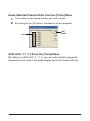
Installing the Software
Is Windows® operating properly?
If Windows is not operating properly, T&D Recorder for Windows may not be installed
correctly or it may not operate properly.
Please quit all other applications.
If other programs are open, please close and quit all of them, making sure to quit all
Quick Start programs such as a virus checker.
1.
2.
Open Windows.
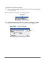
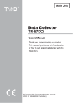
Place the accompanying CD-ROM into your CD-ROM drive. In a few
seconds, the [Install Program] window will appear.
If that window does not automatically open, please open it by double clicking the
CD-ROM icon in [My Computer] on your desktop.
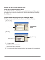
[Install T&D Recorder
for Windows
(TR-5,7xU)]
[Execute]
Button
3.
Select [Install T&D Recorder for Windows] and click the [Execute]
button to start the installation.
4.
To continue installation, follow the directions as they appear.
After installation has been completed the program [T&D Recorder for Windows ]
should appear in the [Start] Menu will be registered in the [Start] Menu's [Start up]
Program.
5
Getting Ready
Using the Software
How to Open
To open, in the Windows Start Menu, under Programs, click [T&D
Recorder for Windows®].
A Launcher Program
Upon opening [T&D Recorder for Windows], a launcher program will
appear with several icons lined up. By clicking on an icon, a graph
display or a settings /communication display for the selected type of
device will appear.
Menu Bar
Icons
Menu Bar
The menus along the bar contain various helpful commands. From each menu, you can
select commands to view or make settings for each of the device types.
Icons
By clicking TR-71U/72U, TR-73U, TR-51A/52, TR-51S/52S and Graph icon, you can
open the Settings and Communication Display. You can also open the Settings and
Communication Display from the [Start] Menu in the Menu Bar.
Getting Ready
6
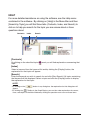
HELP
For more detailed assistance on using the software, see the Help menu
contained in the software. By clicking on [Help] in the Menu Bar and then
[Search by Topic] you will find three tabs (Contents, Index, and Search) to
click on to help you search for the topic you are unsure about or have
questions about.
Contents
Index
Search
[Contents]
By clicking on the classified topic
topic.
mark you will find explanations concerning that
[Index]
Select a keyword from the keyword list and by clicking the [Display] button, the
explanation for that topic will appear.
[Search]
Enter the keyword you wish to search for and click [Start Search]. All topics containing
that keyword will be displayed. Select a topic and click the [Display] button to display
the explanation for that topic.
NOTE:
- By clicking on the [
appear.
] button in any dialog box, the explanation for that dialog box will
- By clicking the [
] Toolbar in the Graph Display, you can then view explanations for menus,
icons, and objects in the Main Window by clicking the question mark arrow on those items.
7
Getting Ready
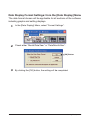
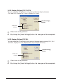
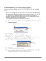
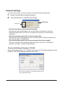
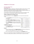
Date Display Format Settings: from the [Date Display] Menu
The date format chosen will be applicable for all sections of the software
including graphs and setting displays.
1.
In the [Date Display] Menu, select "Format Settings".
2.
Check either "Month/Date/Year" or "Date/Month/Year".
[OK] Button
3.
By clicking the [OK] button, the setting will be completed.
Getting Ready
8
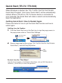
Quick Start (TR-7U / TR-50U)
When Windows is started, the "TR-71U/TR-72U/TR-73U/TR-50U
Quick Start Program" (from here "Quick Start") will be automatically
started. When a TR-50U or TR-7U Series device is connected to
your computer, the Quick Start will make a search and automatically
open the application.
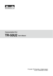
Quitting Quick Start / How to Restart Again
Please see below for how to quit the Quick Start function and how to
restart again.
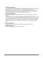
Quitting from the Taskbar
Click the Quick Start icon in the Task tray to view the popup menu; in
the popup menu click on "Quick Start Settings"
1.
Click the Quick
Start icon
2.
Place a check next to [Do not use "TR-71U/TR-72U/TR-73U/TR-50U
Quick Start"] and click the [OK] button.
Check here
[OK]
Button
Re-start from the "Start Menu".
From the list of programs in the Window's Start Menu, click on [T&D Recorder for
Windows] – [Quick Start] to restart the application.
9
Getting Ready
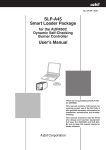
Quit / Start from each application
Click on one of the icons (TR-51S/52S, TR-71U/72U,or TR-73U) in the
Launcher Window.
1.
2.
Click [Software Settings] in the [Settings] Menu.
[Settings] Menu
3.
Remove the check mark from next to [Uppon Connecting a Thermo
Recorder, open the software program.] and click the [OK] button.
With no checkmark: Quick Start will be disabled
With a checkmark: Quick Start will be enabled
[OK]
Button
Getting Ready
10
Connecting a Data Collection Device to the Computer
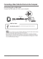
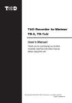
Connecting with a USB Cable
Connect the USB cable (US-15C) to your computer.
USB Port
USB Cable
USB
mini-B Plug
USB-A
Plug
TR-50U
USB Port Mark
The USB cable is a USB-A Plug ⇔ USB mini-B plug type. Please connect to a
place with this kind of mark.
NOTE:
- Before using, it is necessary to have installed the USB device driver.For details about the driver
installation, see the User's Manual that came with the product.
- Make sure that the USB cable is inserted fully, so as not to cause an improper connection.
- Make all necessary Communication Port Settings in the Settings / Communication window for
the Data Logger you are using. For details, see "Communication Port Settings" p.15-. (TR-5S
has no communication port settings).
11
Getting Ready
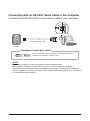
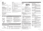
Connecting with an RS-232C Serial Cable to the Computer
Connect the serial (RS-232C) communication cable to your computer.
D-Sub 9 pin female
RS-232C Serial Cable
TR-50C
Examples of serial port marks
The communication cable connector is a D-Sub 9 pin female.
Connect to a place with a mark as such.
NOTE:
- Make sure to connect it to the correct place to ensure communication.
- Make sure that the cable is inserted fully, so as not to cause an improper connection.
- Make all necessary Communication Port Settings in the Settings / Communication window for
the Data Logger you are using. For details, see "Communication Port Settings" p.15. (TR-5S has
no communication port settings) .
Getting Ready
12
Connecting the Data Logger to the Computer
Connect the Data Logger to the computer using the appropriate
method for that type of Data Logger.
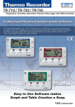
When using a Data Logger with Optical Communication
Compatible Loggers: TR-51S/52S、TR-51A/52/51
1.
Connect the Communication Port to your computer using the provided
communication cable.
Communication Cable
Communication Port
2.
Place the Data Logger on top of the Data collection device as shown in
the figure, making sure that the optical communication spots are
aligned properly.
Place the Data Logger face down
Communication cable that was
connected to your computer
(See pp.11-12)
13
Getting Ready
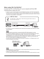
When using TR-71U/72U/73U*1
Connect the TR-71U/72U/73U unit to your computer with the USB
Communication Cable (US-15C).
*1: If necessary, serial communication can be established by using our TR-73U communication
protocol (contact your local dealer) to write a software program. In this case, it will necessary
to connect to your computer using our optional serial communication cable (TR-07C). Please
contact your local provider for more details.
USB Port Mark
The USB cable is a USB-A Plug ⇔ USB mini-B plug type. Please connect to a
place with this kind of mark.
USB mini-B plug
To the data logger
USB A-plug
To your computer
*It is necessary to install a USB device driver. Please see the Hardware User's Manual for details
about installation.
NOTE:
- To ensure proper communication, make sure that the USB cable connection is secure.
- This software is designed to operate TR-71U/72U/73U units with USB connections and cannot
operate the units via serial communication cables. If you wish to use serial cables to
communicate with TR-71U/72U units, please install [Thermo Recorder for Windows 4.11 (E) from
the CD-ROM menu and treat the units as TR-71S/72S units." Note that communication with
TR-73U via serial cable is not supported by the software.
- For more details about the use of [Thermo Recorder for Windows 4.11 (E)] please refer to the
PDF file contained in the CD-ROM.
USB cable already
connected to computer.
NOTE:
- To communicate with a TR-71U/72U unit via serial communication cable, please use our optional
serial communication cable TR-07C.
- If the place of connection is incorrect, communication will not occur.
- To ensure proper communication, make sure that the communication cable connection is secure.
Getting Ready
14
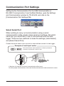
Communication Port Settings
Setting Up the Communication Port for USB Communication or
RS-232C Communication. From the Main Window, open the Settings
and Communication window for TR-51A/52, and click on the
[Communication Port Settings] Tab.
Click
Select Serial Port
When wishing to carry out communication using a serial
communication cable, please make serial port settings. Set which
serial port you would like to use to communicate with the data
logger. There are two methods to make the settings: [Auto-Detect]
and [Select Serial Port].
Connect the serial cable to port you wish to use and then connect it to the logger.
Examples of serial port marks
The communication cable connector is a D-Sub 9 pin female.
Connect to a place with a mark as such.
- If the place of connection is incorrect, communication will not occur.
- To ensure proper communication, make sure that the communication cable connection is secure.
15
Getting Ready
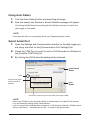
Using Auto Detect
1.
2.
Click the [Auto Detect] button and searching will begin.
After the search has finished, a Search Results message will appear.
By clicking the [Set] button the setting will be finalized as the port to which the
data logger is connected.
NOTE:
- If Auto detection does not work properly, please see [Troubleshooting] for advice.
Select Serial Port
1.
Open the Settings and Communication window for the data logger you
are using, and click on the [Communication Port Settings] Tab.
2.
Check the COM Port you wish to use for T&D Recorder for Windows in
the [Possible COM Ports] list.
3.
By clicking the [OK] button the setting will be finalized.
[Auto Detect]
Button
check
Com Ports for which
communication is
possible
[Set]
Button
Check here, when using Communication Port above COM9
NOTE:
- When using TR-50U to make recording settings or download data, first open TR-5S and then
carry out the desired settings and/or communication.
- If you are using a Data Collecting Device which has a USB interface (other than TR-50U), please
place a check next to “Communicate via USB” as shown in the above screen.
Getting Ready
16
17
Getting Ready
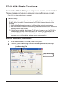
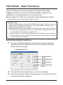
TR-71U/72U/73U:Basic Functions
Display Names and Functions
Menu Bar
Toolbar
Device List
Settings
Area
Device Properties
[Menu Bar]
The menus along the bar contain various helpful commands. From each menu, you can
select commands to view or make settings for each of the device types.
[Toolbar]
The commands that are used most frequently have been arranged as buttons.
[Device List]
TR-71U/72U/73U units connected to the computer by USB cable will be displayed as
icons here. In order to make recording settings or download recorded data, it is
necessary to first select a device from the device list. The type of icon used in the
display can be changed in the [View] Menu.
[Device Properties]
Information about the device selected in the device list will be displayed here. If more
than one data logger has been selected no information will be displayed.
[Settings Area]
By clicking on the [Download Recorded Data] tab or the [Start Recording] tab, you can
open the settings display for that function.
Basic Function - TR-71U/72U/73U
18
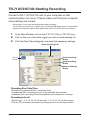
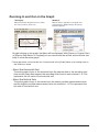
TR-71U/72U/73U: Starting Recording
Connect a TR-71U/72U/73U unit to your computer so that
communication can occur. Please make sure that your computer
clock settings are correct.
-
Please see p.14 for more information about how to connect.
The first time you connect it is necessary to install the USB device driver. For information
about how to install the device driver please see the TR-71U/72U/73U User's Manual.
1.
2.
3.
In the Main Window, click on the [TR-71U/72U] or [TR-73U] icon.
Click on the icon of the data logger you wish to make settings for.
Click the [Start Recording] tab, and make the necessary settings.
[Start Recording] Tab
Click on
the icon
[Start Recording]
Button
[Stop Recording]
Button
[Receive Settings]
Button
Recording Start Date/Time
(Selections: Programmed Start / Immediate Start)
Programmed Start: recording will start on the specified date and time.
Immediate Start: recording will start immediately upon completion of settings.
Recording interval
(Select from:1, 2, 5, 10, 15, 20, 30 seconds1, 2, 5, 10, 15, 20, 30, 60 minutes)
Click on [ ▼ ] and select the desired recording interval from the drop-downlist.
19
Basic Function - TR-71U/72U/73U
Recording Mode
Selections: One-time/Endless
- One-time:
When the possible number of recorded data readings(8000 readings per channel) is
reached, recording stops.
- Endless :
When the possible number of recorded data readings is reached, the oldest data is
overwritten and recording continues.
Device Name/Channel Name
Make settings for each data logger concerning the device names and channel names.
Device Name: Up to 16 characters
Channel Name: Up to 8 characters
4.
After having completed the recording conditions settings, transmit the
settings to the data logger by clicking the [Start Recording] button.
5.
After the transmission has been completed, a message will appear;
click the [OK] button to activate the settings.
[Stop Recording] Button
Clicking this button will stop a recording session already in progress.
[Receive Settings] Button
Clicking this will allow you to view recording condition settings and recording status
information from the data logger.
Basic Function - TR-71U/72U/73U
20
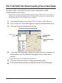
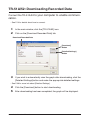
TR-71U/72U/73U: Downloading Recorded Data
Connect a TR-71U/72U/73U unit to your computer so that
communication can occur.
-
Please see p.14 for more information about how to connect. The first time you connect it is
necessary to install the USB device driver. For information about how to install the device
driver please see the TR-71U/72U/73U User's Manual.
1.
2.
3.
In the Main Window, click on the [TR-71U/72U] or [TR-73U] icon.
Click on the icon of the data logger you wish to download data from.
Click the [Download Recorded Data] tab.
[Download Recorded Data] Tab
Select a data
logger
[Download]
button
[Detailed Settings]
Button
4.
-
For more information about Detailed Settings see p.22.
5.
6.
21
If you wish to automatically display the graph upon the completion of
downloading, click the [Detailed Settings] button to make such a
setting.
Click the [Download] button to begin downloading data.
After downloading has been completed a graph will be displayed.
Basic Function - TR-71U/72U/73U
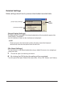
Detailed Settings
Make settings about how to process downloaded recorded data.
[OK]
Button
[Graph Display Settings]
[File Name Settings]
[Graph Display Settings]
By checking here, the graph for the downloaded data will automatically appear after
downloading is completed.
Up to 8 channels of data can be simultaneously displayed.
NOTE:
- If there are more than 8 channels of data, that data cannot be displayed
automatically and must be opened from the data file.
[File Name Settings]
You can choose to save downloaded data using a default file name or by assigning a
name each time.
1. Choose the type of processing you desire.
2.
By clicking the [OK] button the setting will be completed.
- You can specify the type of default file name under [File]– [File Names and Folders].
Basic Function - TR-71U/72U/73U
22
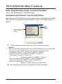
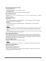
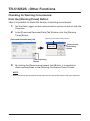
TR-71U/72U/73U: Other Functions
Open Temp/Humidity Graph: from the [File] Menu
Opens the Temperature / Humidity Graph.
File Names and Folders: from the [File] Menu
Specify how you wish the files to be named upon downloading recorded
data. Also you can select in which folder to use to save data for each
device.
Check one from the
[Default File Name
Settings]
1.
[OK]
Button
Check which type of file name you wish to use to save data.
Example:
Device Name:Refrigerator/Serial No.:00001234/Date and Time:2003/05/
12(yyyy,mm,dd)at 14:30:15/with Data Format Extension:TRX
- Device Name+Date/Time : Refrigerator_20030512_143015.trx
- Internal ID +Date/Time : 00001234_20030512_143015.trx
- Device Name+ Internal ID +Date/Time :
Refrigerator_00001234_20030512_143015.trx
- Date / Time+Device Name : 20030512_143015_Refrigerator. trx
- Date / Time+Internal ID : 20030512_143015_00001234.trx
- Date/ Time+Device Name + Internal ID :
20030512_143015_Refrigerator_00001234.trx
2.
23
By clicking the [OK] button, the settings will be completed.
Basic Function - TR-71U/72U/73U
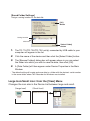
[Saved Folder Settings]
Assign a saving location for the data file.
[OK]
Button
Saving Location
Click here
[Select Folder]
Button
1.
The TR-71U/TR-72U/TR-73U unit(s) connected by USB cable to your
computer will appear in the list.
2.
3.
Click the name of the device and then click the [Select Folder] button.
4.
A [Data Folder] will then appear under Device Properties in the Main
Window.
The [Browse Folders] dialog box will appear where in you can select
the folder into which you wish to save the data, then click [OK].
- The default setting will create and save data to a folder with the device's serial number
in the same folder where T&D Recorder for Windows was installed.
Large Icon/Small Icon: from the [View] Menu
Changes the icon size in the Device List between large and small.
《Large Icon》
《Small Icon》
Basic Function - TR-71U/72U/73U
24
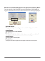
Monitor Current Readings:from the [Communication] Menu
You can monitor at set intervals the current readings of data logger or
loggers selected from the device list and have those readings displayed.
《Settings Display》
[Settings] button:
This opens a window where settings can be made for the display colors and the
monitoring interval for current readings.
[Close] button :
Quit the Monitoring of Current Readings.
[Reset] button :
Click to reset the display for highest and lowest measurements; the new display will
show highest and lowest measurements from the time of resetting.
[Graph] button :
Click this to hide or view the graph.
[Clear] button :
Clicking this will clear the graph and a new graph will be drawn from that point.
25
Basic Function - TR-71U/72U/73U
Search for TR-71U/TR-72U/TR-73U:
from the [Communication] Menu
If a TR-71U, TR-72U or TR-73U is connected, but does not show up in
the Device List, click this to search for Thermo Recorders by scanning
the USB ports.
Device Name Settings:from the [Settings] Menu
Settings can be made for Device Names and Channel Names.
[TR-71U/72U]
Enter a name
[Send Settings]
Button
[TR-73U]
Enter a name
1.
[Send Settings]
Button
Enter a name.
- Device Name: up to 16 characters
- Channel Name: up to 8 characters.
2.
By clicking the [Send Settings] button, the changes will be completed.
Basic Function - TR-71U/72U/73U
26
LCD Display Settings:from the [Settings] Menu
Settings can be made for the Thermo Recorder's LCD display, such as,
changing the temperature unit and turning the display on or off.
[TR-71U/72U]
Check one
of these
[Send Settings]
Button
[TR-73U]
Check one
of these
1.
2.
27
[Send Settings]
Button
Check either Celsius or Fahrenheit.
By clicking the [Send Settings] button, the changes will be completed.
Basic Function - TR-71U/72U/73U
[LCD Display Pattern] TR-71U/72U
You can select the LCD display from 3 patterns: Alternate display between
Ch.1 and Ch.2, Display Ch. 1 only, or Display Ch. 2 only.
[Send Settings]
Button
Check one
of these
1.
2.
Check one of the patterns.
By clicking the [Send Settings] button, the changes will be completed.
[LCD Display Pattern] TR-73U
You can select the LCD display from 4 patterns: Alternate display among Ch.1, Ch.2
and Ch.3, Display Ch.1 only, Display Ch.2 only or Display Ch.3 only.
[Send Settings]
Button
Check one
of these
1.
2.
Check one of the patterns.
By clicking the [Send Settings] button, the changes will be completed.
Basic Function - TR-71U/72U/73U
28
Adjustment Settings:from the [Settings] Menu
By setting adjustment values beforehand, you can record and display
the post- adjusted measurement values. You can choose from two
adjustment methods: 1-point and 2-point. Adjustment will be carried out
using an adjustment equation of Y = aX + b; where X is the preadjusted measurement value and Y is the post-adjusted value.
Rough Guidelines for Adjustment
1 point Adjustment: Use when measuring in a range of ± 20℃ .
2 point Adjustment: Use when measuring in a wide range.
NOTE:
- When adjusting at 2 points, make sure the difference in points is at least 10℃ .
- When measuring in a wide range and adjusting at 2 points, make sure that the adjustment
values reflect the range you are measuring.
- We cannot guarantee that after carrying out adjustment the measuring accuracy will improve for
all measuring ranges.
1.
Check the channel you wish to adjust.
Check here
Check one, and enter
the value
[Send Settings]
Button
[Save File] Button
[Read File] Button
[History] Column
2.
Place a checkmark next to either [1 Point Adjustment] or [2 Point
Adjustment] and enter the [Before] and [After] values.
3.
By clicking the [Send Settings] button, the adjustment settings will be
completed.
- The data logger can store up to 4 adjustment values, the adjustment history will display
up to 4 channels at one time.
29
Basic Function - TR-71U/72U/73U
[1 Point Adjustment]
This adjustment method changes only the offset (b) where the slope (a) is considered 1.
For example, TR-71U is measuring 10℃ , but the standard says the actual
measurement should be 10.2℃ . Enter 10 in the Before Adjustment box and 10.2 in
the After Adjustment box. The conversion equation will be Y = X + 0.2 and for all
measurements an adjustment to the offset of +0.2 will be made.
[2 Point Adjustment]
The adjustment equation will be calculated from two points: the slope (a) and the
offset(b).
For example, the TR-71U reads 0℃ when the standard thermometer reads 0.4℃ , and
TR-71U reads 10℃ when the standard says the true measurement is 10.2℃ . In this
case the slope(a)is 10.2-0.4/10-0 = 0.98. The offset is 0.4, so the conversion equation
becomes Y = 0.98X + 0.4. The range of the slope is 0<a< = 2. Entries are valid to
one decimal point, but after calculation up to four digits are valid for the slope and
offset.
[Save File] Button
Assign a name to the adjustment setting values and save them to a file.
[Read File] Button
Read adjustment setting values from a saved file.
Basic Function - TR-71U/72U/73U
30
Software Settings:from the [Settings] Menu
General software settings for TR-71U/TR-72U/TR-73U can be made
here.
[Upon connecting a Thermo Recorder, open the Software Program]
This setting opens the software program upon the connection of a TR-71U/TR-72U/
TR-73U unit via USB cable. If the setting is ON, the Quick Start Program will
periodically communicate with the device driver and upon the detection of a USB
connection will open the main software program.
- For more details about [Quick Start] and how to quit it, see P. 9.
1.
Place a check next to [Upon connecting a Thermo Recorder, open the
Software Program].
With no checkmark: Quick Start will be disabled
With a checkmark: Quick Start will be enabled
[OK]
Button
2.
Click [OK] to complete the setting.
[Temp. Unit to be displayed in Software Program]
Select whether to use Celsius or Fahrenheit as the displayed unit of temperature when
monitoring current readings and using the adjustment function.
1.
Check either unit of temperature (Celsius or Fahrenheit).
[OK]
Button
Check here
2.
3.
31
Click [OK] to complete the setting.
After completing settings, please close the TR-71U/72U or TR-73U
program and reopen it to make settings effective.
Basic Function - TR-71U/72U/73U
TR-51A/52: Basic Functions
Connect the TR-51A/52 to your computer to enable communication.
Please make sure that your computer clock settings are correct.
- See P.13 for details about how to connect.
Before Using…
This section explains operations for when using with either Communication Port
TR-50C. When using with Communication Port TR-50U, please take note of the
following:
① Although the Settings window layout is different, the contents are the same.
② The communication speed for downloading and other communications will be the
same as with our older models.
③ If Quick Start is enabled, by placing a TR-5 Series Logger on top of a TR-50U to
make recording settings or download data, the software will automatically be
opened. If Quick Start has been disabled, please open TR-5S from the launcher
menu and carry out the desired settings and/or communication.
Set the Recording Conditions
1.
2.
In the Main Window, click the [TR-51A/52] icon.
Click the [Start Recording] Tab and make any necessary settings.
[Start Recording] Tab
[Start Recording]
button
Basic Function - TR-51A/52
32
Type
(Select:TR-51A / TR-52)
Select depending on the device you wish to make settings for.
Channel Name
Channel names can be entered with up to 8 letters.
Recording Start Date / Time
Select: Programmed Start / Immediate Start
- Programmed Star
Recording will begin on the day and time entered.
- Immediate Start
Recording will begin as soon as settings are completed.
Recording Interval
Select from:1, 2, 5, 10, 15, 20, 30 seconds / 1, 2, 5, 10, 15, 20, 30, 60 minutes.
By clicking [ ▼ ] you can select from the recording interval list.
- TR-51A cannot be set using seconds.
Recording Mode
Select from: One-time / Endless
- One-time:
When the number of readings has reached 16,000, the unit display will read FULL
and recording will automatically stop.
-Endless:
When the number of readings reaches 16,000, the next one will overwrite the oldest
or first reading.
Unit of Temperature
Select from: Celsius [℃ ] or Fahrenheit [゜
F ].
F ].
Change the display of temperature on the data logger between [℃ ] and [ ゜
33
3.
After making all the desired settings, click the [Start Recording] button
to transmit them.
4.
After transmission has been completed the communication result will
appear. By clicking [OK], the set-up process will be finished. By clicking
[OK], you can close the window.
Basic Function - TR-51A/52
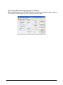
*Recording Start Settings Display for TR-50U
When making settings via a TR-50U, the layout for the Settings display will be as below:
The contents of the settings and the procedure are the same.
Basic Function - TR-51A/52
34
TR-51A/52: Downloading Recorded Data
Connect the TR-51A/52 to your computer to enable communi-
cation.
- See P.13 for details about how to connect.
1.
2.
In the main window, click the [TR-51A/52] icon.
Click on the [Download Recorded Data] tab.
Download Recorded Data
[Download]
Button
[Detailed Settings]
Button
3.
If you wish to automatically view the graph after downloading, click the
[Detailed Settings] button and make the appropriate detailed settings.
- See P.36 for more info about [Detailed Settings].
4.
5.
35
Click the [Download] button to start downloading.
After downloading has been completed, the graph will be displayed.
Basic Function - TR-51A/52
Detailed Settings
You can make settings for the processing of the downloaded recorded data.
1.
2.
Select the desired processing method.
Click [OK] button to complete the setting.
[OK] Button
Check one
[After downloading, automatically show graph]
After data has been downloaded it will automatically be displayed in the Temp /
Humidity graph Window. The File is not saved and if necessary should be done
separately.
[After downloading, specify file in which to save data]
After data has been downloaded, the [Save File] dialog box will appear wherein you
can save the data to a specified file.
[After downloading, specify file name and automatically show graph]
The data is saved to the specified file and the graph for that file is automatically
opened in the Temp / Humidity Graph Window.
*Download Settings Display for TR-50U
When downloading data via a TR-50U, the layout for the Settings display will be
as below: The downloading procedure is the same
When using a TR-50U, it is possible to specify which
data to download by time.
Basic Function - TR-51A/52
36
TR-51S/52S:Basic Functions
Here all settings and communication for TR-51S/52S (Data
Loggers) can be carried out. Connect the Data Logger to the
Computer so communication can be carried out.
Please make sure that your computer clock settings are correct.
- For details about connecting the data logger, see p. 13.
Before Using…
In order to make optimum use of the TR-51S/52S Data Logger's features, we strongly
suggest using in conjunction with TR-50U. This section explains operations when
using with Communication Port TR-50U.
When using with either Communication Port TR-50C, please take note if the following:
① TR-51S will be recognized as TR-51A and TR-52S will be recognized as TR-52;
for more details about operations see from p.32.
② Some functions, such as "Warning Settings" and "Adjustment", cannot be used.
③ The communication speed for downloading and other communications will be the
same as with our older models.
Set the Recording Conditions
1.
Click the [Start Recording] tab, and make the necessary recording
condition settings. For details about the various items and buttons,
please see the next page.
[Recording Start] Tab
[Recording Start]
Button
[Detailed Settings]
Button
[Recording Start]
Button
[Warning Settings]
Button
2.
3.
37
Click the [Start Recording] button to transmit the settings.
After the transmission result message appears; click the [OK] button to
complete the setting procedure.
Basic Function - TR-51S/52S
[Recording Start Date / Time]
- Programmed Start
Recording will begin on the set date and time.
- Immediate Start
Recording will begin once settings have been completed
[Recording Interval]
Selections: 1, 2, 5, 10, 15, 20, 30 seconds or 1, 2, 5, 10, 15, 20, 30 minutes. (Default
setting is 10 min.)
[Recording Mode ]
- One-time
Upon reaching capacity of 16000 readings、"FULL"will appear on the LCD display
and recording will automatically stop.
- Endless
Upon reaching capacity of 16000 readings、the oldest data is overwritten and
recording continues.
NOTE:
- The start date and time for a programmed recording start is based upon your computer system
clock. If your computer clock is not set correctly, a programmed recording start may not start
properly.
- The estimated finish date and time of recording in one time mode will be automatically calculated
from the set recording interval and starting time.
[Recording Start] Button
After making the necessary recording condition settings, click the [Recording Start]
button and the settings will be transmitted to the Data Logger. If you have selected a
programmed recording start, the unit will be put into recording wait status. If you have
selected immediate start, recording will begin.
[Get Settings] Button
Reads the settings from the connected Logger.
NOTE:
- When using Communication Port TR-50C, it is not possible to use the "Get Settings" function.
[Stop Recording] Button
Recording will stop.
[Warning Settings] Button
Opens the "Warning Settings" window wherein settings for "Upper and Lower Limits"
and "Judgment Time" can be made.
Basic Function - TR-51S/52S
38
Making Warning Settings: from the [Warning Settings] button
Under the [Start Recording] tab, click on the "Warning Settings" button
to open the "Warning Settings" window.
1.
2.
Place a check next to [Set Limits].
Settings can be made for the Upper and Lower Limits as well as the
Judgment Time.
-
The Upper-Lower Limits must be set in a range from ― 60℃ to 155℃
-
The judgment time can be set from the following selections: 10, 15, 20, 30 seconds or 1, 2, 5,
10, 15, 20, 30, 60 minutes.
By placing a checkmark, the settings for that item will become active.
Judgment Time
[OK]
Button
3.
4.
[Cancel]
Button
By clicking the [OK] button, a confirmation message will appear.
By clicking the [OK] button, you will be returned to the [Start
Recording] Tab window
- Judgment Time
A warning occurs when either the set upper or lower limit has been exceeded or when
the judgment time has been exceeded. Upon a warning, the warning LED on the
TR-51S/52S will flash and a warning mark will appear in the display.
- Starting the Warning Monitoring Function…
If these settings are made in an environment where one of the limits is being
exceeded and recording is started, the monitoring function will enter "wait" mode.
Once the current measurement falls within the set limits, the monitoring function will
begin to operate.
39
Basic Function - TR-51S/52S
TR-51S/52S:Downloading Recorded Data
1.
Set the Data Logger so that communication can be carried out with the
Computer.
2.
3.
Open the [Download Recorded Data] Tab Display.
With [Detailed Settings], it is possible to make settings for what type of
processing you wish to occur after downloading.
[Download Recorded Data] Tab
Place a check here if
you wish to specify
data by time.
[Download]
Button
[Detailed Settings]
Button
4.
If you wish to download all of the data, simply click the [Download]
button.
5.
If you wish to specify data by time for downloading, choose the time
range and click the [Download] button.
[Detailed Settings] Button
This opens the window in which settings for the processing of data after it has been
downloaded can be made Select from the four processing methods.
[OK] Button
[Destination Folder
Settings] Button
Selecting the Data Processing Method
[A Graph will automatically be shown]
[Assign a File Name for the saved data]
[Assign a File Name for the saved data and automatically show graph]
[Automatically save file]*
* Click the [Destination Folder Settings] button to specify the file saving location. A file with the
name [download date and time_channel name.trx] will be saved in the specified folder.
Basic Function - TR-51S/52S
40
TR-51S/52S : Other Functions
Checking for Warning Occurrences:
from the [Warning Times] Button
Here it is possible to check the time(s) of warning occurrences.
1.
Set the Data Logger so that communication can be carried out with the
Computer.
2.
In the [Download Recorded Data] Tab Window, click the [Warning
Times] Button.
[Download Recorded Data] Tab
[Warning Occurrence Time] Column
[Receive most
recent time]
Button
[Warning Times]
Button
3.
By clicking the [Receive most recent time] Button, it is possible to
check warning times in the [Warning Occurrence Time] Column.
NOTE:
- Even if more than one warning occurred, only the first one will be shown in the most recent list.
41
Basic Function - TR-51S/52S
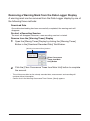
Removing a Warning Mark from the Data Logger Display
A warning mark can be removed from the Data Logger display by one of
the following three methods:
Download Data
Once data downloading has been successfully completed, the warning mark will
disappear.
Re-start a Recording Session
The mark will disappear whenever a new recording session is started.
Remove from the [Warning Times] Display
1. Open the [Warnig Times] Display by clicking the [Warning Times]
Button in the [Download Recorded Data] Tab Window.
[Warning Occurrence Time] Column
[Clear Occurrence
Times from Main
Unit] Button
2.
Click the [Clear Occurrence Times from Main Unit] button to complete
the removal.
-
This will have no effect on the already recorded data; measurement and recording will
continue without interruption.
-
Confirm that in the Warning Occurrence Time Column, [None] appears.
Basic Function - TR-51S/52S
42
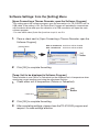
Software Settings: from the [Setting] Menu
[Upon Connecting a Thermo Recorder, open the Software Program]
This setting opens the software program upon the connection of a TR-51S/52S unit via
USB cable. If the setting is ON, the Quick Start Program will periodically communicate
with the device driver and upon the detection of a USB connection will open the main
software program.
- For more details about [Quick Start] and how to quit it, see P. 9.
1.
Place a check next to [Upon Connecting a Thermo Recorder, open the
Software Program].
[Setting] Menu
With no checkmark: Quick Start will be disabled
With a checkmark: Quick Start will be enabled
[OK]
Button
2.
Click [OK] to complete the setting.
[Temp. Unit to be displayed in Software Program]
Select whether to use Celsius or Fahrenheit as the displayed unit of temperature when
monitoring current readings and using the adjustment function.
1.
Check either unit of temperature (Celsius or Fahrenheit).
[OK]
Button
Check here
2.
3.
43
Click [OK] to complete the setting.
After completing settings, please close the TR-51S/52S program and
reopen it to make settings effective
Basic Function - TR-51S/52S
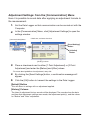
Adjustment Settings: from the [Communication] Menu
Here it is possible to record data after applying an adjustment formula to
the measurement.
1.
Set the Data Logger so that communication can be carried out with the
Computer.
2.
In the [Communication] Menu, click [Adjustment Settings] to open the
settings window.
[Communication] Menu
Check one, and enter the value
[Send Settings]
Button
[Initialize]
Button
[History] Column
3.
Place a checkmark next to either [1 Point Adjustment] or [2 Point
Adjustment] and enter the [Before] and [After] values.
-For more about guidelines for adjustment, see p. 30.
4.
By clicking the [Send Settings] button, a confirmation message will
appear.
5.
Click the [OK] button to transmit the settings to the Data Logger.
[Default] Button
This will return to settings with no adjustment applied.
[History] Column
The latest 4 adjustment history records will be displayed. The records show the date
and time that adjustment settings were made, the adjustment point(s), and the values
for "Before" and "After" adjustment.
Basic Function - TR-51S/52S
44
Temperature / Humidity Graph
Open the Graph display by clicking the icon [Temp/Humid Graph] in the
Main Window.
Click
-
Open by selecting [Open Temp/Humidity Graph] in the [File] Menu of the TR-71U/72U/
73U, TR-51A/52, TR-51S/52S Settings and Communication Window.
-
If you have checked [After downloading, automatically display graph] in the detailed settings,
the graph program will automatically open.
NOTE:
- When viewing a Graph, small differences in time may occur. For details see "Troubleshooting"
on p.64.
45
Temperature/Humidity Graph
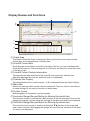
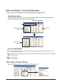
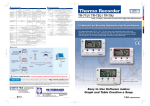
Display Names and Functions
①
⑦
⑤
⑥
⑧
②
③
④
① Graph Area
The area in which the Graph is displayed The horizontal axis shows time and the
vertical axis shows temperature / humidity data.
② A and B Cursor Bars
By clicking the arrow buttons at the left and right of the bar, you can simultaneously
move the A/B cursors. Click and drag the A or B button on the bar to move the cursor
to the left or right.
③ A and B Cursor Position Information
The approximate date and time for the A and B cursor positions and the time
difference between the A cursor and the B cursor is displayed.
④ Channel Info Display
The detailed data info for each channel 1 to 8 is displayed below the Graph Display.
⑤ Menu Bar
Menus are lined up which contain various commands. They are used to view data or
to make settings for the various functions in each menu.
⑥ Toolbar (Icons)
Buttons appear for frequently used commands.
⑦ Horizontal Gauge Bar and Button for Moving Horizontal Axis
▲
▼
The time axis moves by clicking the [
] buttons at the left and right of the bar. By
dragging the gauge you can move left and right to the data you want to be displayed.
⑧ Horizontal Gauge Bar and Button for Moving Horizontal Axis
The vertical axis moves up or down by clicking the[ ▼▲ ]buttons at the upper and
lower sides of the bar. By dragging the gauge you can move up and down to the data
you want to be displayed.
Temperature/Humidity Graph
46
Channel Info Display Items
ch
Drag the channel name / number you wish to move to the newly desired channel
name / number position and drop it.
Name
Channel Data Name
Interval
Recording Interval
Sample
Number of data
Max.
Highest Reading
CursorA
Cursor A position data
Min.
Lowest Reading
CursorB
Cursor B position data
Avg.
Average Value
A<->B
Calculated Temp / Humidity
Difference between Cursor A and B
Unit
Unit of measurement
When opening data recorded in TR-73U units into a graph
When opening a file containing barometric pressure data ("thp" format
file), the window is different from the standard, with the scale for
barometric pressure appearing on the right side.
*For details, see Temperature/Humidity Graph [Help]-[Keyword]-[About Barometric Pressure].
Scale for Barometric Pressure
47
Temperature/Humidity Graph
Zooming In and Out on the Graph
〔Enlarged〕
With the left button drag the mouse to outline
the area you want to zoom in on.
〔Reduce〕
With the mouse, right click on the graph and
select [Return to Original Size] in the pop-up
Menu that appears.
By right clicking on the graph, the Menu will be displayed. With [Return to Original Size]
or [Step-by Step Return to Original] you can return both the vertical and horizontal axis
back to show the entire graph.
* These operations can be carried out via commands in the [Graph] Menu or by clicking icons in
the Toolbar as above.
- About the Horizontal Axis
The entire graph shows in the horizontal axis the nearest data to the recording start
time and the latest data nearest the recording finish time for each channel 1- 8. This
represents the full scale of the horizontal axis.
- About the Vertical Axis
The entire graph shows in the vertical axis the lowest possible measurement value
and the highest possible measurement value for channels 1- 8. This represents the
full scale of the vertical axis.
Temperature/Humidity Graph
48
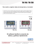
Data List Display : from the [View] Menu
This is a list of the data that was displayed in graph form.
[Date/Time] Button:
By clicking this button, you can shift the display between the recorded date and the
amount of elapsed time since recording started.
[Date/Time] Button
①
Recorded Date
Display
scroll Bar
Elapsed Time
Display
Color Coded Display
Green: Dates and times for data which fall within the calculation range for determining high, low and
average measurements.
Black: Dates and times outside the calculation range for determining high, low and average measurements
RED: Highest Value BLUE : Lowest Value
PINK : Average Value
Menu Display Using the Mouse
By right clicking on the list, the Menu will be displayed.
49
Temperature/Humidity Graph
Graph Maintenance
Changing graph display colors: from the [View] Menu
You can change the letters used in the data list display for each channel
between monochrome and channel color.
[View] Menu
The letter colors
will be changed.
Selected Channels ON/OFF: from the [View] Menu
1.
By moving the mouse to [Selected Channels ON/OFF], the channel
numbers are displayed.
2.
Click the channel number you wish to view or hide.
Check
- The same operation can be done by clicking on the channel number icons in the
Toolbar.
Temperature/Humidity Graph
50
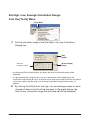
Set High, Low, Average Calculation Range:
from the [Tools] Menu
[Tool] Menu
1.
Set the calculation range in the [Set High, Low, Avg. Calculation
Range] box.
[OK]
Button
Enter the
numerical values.
[Entire Graph]
button
- By clicking the [Entire Graph] button, the dates and times for the entire graph will be
displayed.
- If in the graph display, you place the A cursor at the position for the beginning of the
calculation range and the B cursor at the end of the range, those dates and times will appear
as the new range in the [Set High, Low, Average Calculation Range] Display when it is
opened.
2.
51
By clicking the [OK] button, the high, low, and average values for each
channel of data in the list will be changed. In the graph display, the
data for the calculation range that you have set will be displayed.
Temperature/Humidity Graph
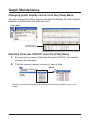
Edit Recording Conditions: from the [Tools] Menu
1.
By clicking the [Ch.] button of the channel you wish to edit, the [Name]
and [Started Date/Time] in the "Edit Items" display will show info for
that channel number.
[OK]
Button
Channel Number
The selected
channel number
[Restore]
Button
Edit Items
- Name: Up to 32 letters can be entered.
- Starting Date/Time: The month, day, year, hour, minute and second can be changed.
2.
By clicking the [OK] button after changing, the setting will be
completed.
-
If you wish to continue to change other channels, repeat the process as in 1.
-
The [Restore] button is only effective while making changes. After clicking the [OK] button the
settings cannot be restored to the original settings.
Temperature/Humidity Graph
52
Re-order Channel Data: from the [Tools] Menu
You can re-order the data during graph display. There are two methods
to use when re-ordering channels:[Re-order by Dragging a Channel
Number] and [Specify the Channel Numbers to be Moved].
EX:Re-order by Dragging a Channel Number
[OK]
Button
[ If you wish to move Ch.3 to Ch.7]
Drag the channel number you wish to
move (Ch 3) to the newly desired channel
number position (Ch 7) and drop it.
[Restore]
button
[Re-order]
Button
[Specify the Channel Numbers to be Moved]
Set as such: "From" → Ch.3 (original position),
"To" → Ch.7 (desired position); then click the
[Re-order] button. Click the [OK] button to
complete the settings. position (Ch 7) and drop
it.
[OK] Button
After make the necessary settings, by clicking the [OK] button, the channels will be
re-ordered and the graph will be re-drawn.
[Restore] Button
This command will become invalid after the settings procedure has been completed
and the [OK] button has been clicked. If you wish to restore channels, please re-order
channels again by following the above procedures.
53
Temperature/Humidity Graph
Erase Selected Channel Data:from the [Tools] Menu
1.
2.
Put a check on the channel number you wish to erase.
By clicking on the [OK] button, the deletion will be completed.
[OK]
button
Check
Shift Unit ( ℃ / ゜
F ):From the [Tools] Menu
By clicking on [Shift Unit( ℃ / ゜
F )], you can automatically change the
temperature unit scale in the graph display and in the channel info list.
Temperature/Humidity Graph
54
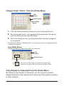
Change Graph Colors: from the [Tools] Menu
[OK]
Button
[Default] Button
[Line Width]
Button
《Color Sample》
1.
Click the channel number of which you wish to change the color.
2.
By clicking each button, color samples will be displayed. Choose the
color you want and click the [OK] button.
3.
After confirming the color, by clicking the [OK] button the change will
be completed.
* By clicking the [Return to Default] button, you will return to the color settings when the
software was opened.
[Line Width] Button
Change the width of the data lines and/or the scale lines.
[OK]
Button
[Default] button
・Every time you click on ▲ , the numerical value gets larger.
・Every time you click on ▼ , the numerical value gets smaller.
Copy Display to Clipboard:From the [Tools] Menu
By clicking [Copy Display to Clipboard], you can copy the currently
displayed window to the clipboard and make use of the graph by pasting
to other software.
55
Temperature/Humidity Graph
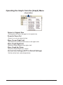
Operating the Graph: from the [Graph] Menu
[Graph] Menu
Return to Original Size
Clicking here will return the graph to its original size.
Zoom In / Zoom Out
Zooms in or out one step at a time
Move Cursor Right / Left
Simultaneously move the AB Cursors to the right or left.
Move Graph Right/Left
Move the Graph Display to the right or left.
Move Graph Up / Down
Move the Graph Display up or down.
Vertical Axis Settings (AUTO in Default Settings)
Set the vertical axis scale (temperature)
Temperature/Humidity Graph
56
Vertical Axis Settings (AUTO in Default Settings) :
from the [Graph] Menu
1.
Check either [Auto] or [Manual].
AUTO:
The vertical axis will automatically be changed according to the values of the data.
MANUAL:
You can set the upper and lower values of the vertical axis scale.
[TR-5, TR-5S, TR-71U/72U]
[OK]
button
Enter the range of the
vertical axis scale.
[TR-73U]
[OK]
button
Enter the range of the
vertical axis scale.
2.
57
Click [OK] to complete the settings.
Temperature/Humidity Graph
Saving Recorded Data
If you have checked [After downloading, automatically show graph.],
make sure to save data after displaying the graph or editing any
data.
3 Ways to Save Files : from the [File] Menu
[Overwrite All Data]
Will save any changes to file without changing File Name and Saving Location. The
same operation can be carried out from [Save] in the Toolbar.
[Save All Data as...]
Save with a new File Name.
[Save Display Data as]
Save only that data in the current display. This is handy when you wish to save only the
desired data.
EX: [Save All Data as...]
1. Click [Save All Data as...] in the [File] Menu.
2.
Specify the [Location] and enter a [File Name].
Specify Location
Enter a File Name
3.
[Save]
Button
Click [Save] to complete the saving process.
Temperature/Humidity Graph
58
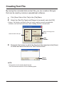
Creating Text File
By saving the recorded data as text file, you can create a file type
that can be read by common spreadsheet software.
1.
2.
Click [Save Data in Text File] in the [File] Menu.
Select the [Text File Type] and [Range to be saved], and click [OK].
- Comma, Tab, Space, and Semi-colon are codes used by common spreadsheet
software, such as Excel and Lotus, when reading Text File to divide cells.
Select the Text File Type
Select the Range to be
Saved
[OK]
Button
3.
Designate the location to which the file should be saved and click [Save]
to create and save the data as a Text File document.
[Save]
Button
NOTE:
- The extension for the created file will be [.txt].
- Text File cannot be read into T&D for Windows graphs.
59
Temperature/Humidity Graph
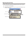
Opening Saved Files
To open a previously saved file, designate the file name to open it.
1.
2.
Click [Open] in the [File] Menu.
Select the name of the data you wish to open and click [Open] to view
the data in graph form.
Select a file
Selected File Name
[Open]
button
Selected File Info
Temperature/Humidity Graph
60
Reinstalling the Software
Before reinstalling or updating the software, make sure to carry out
the uninstall program first. Before you begin the uninstall program,
first make sure to quit all T&D Recorder for Windows programs.
1.
2.
In the Windows Control Panel, click on [Add/Remove Programs].
3.
The [Install Shield Wizard] will appear. Check [Remove], and click [Next].
From the list of currently installed programs, select [T&D Recorder for
Windows] and click the [Change / Remove] button.
Check [Remove]
[Next] Button
4.
5.
Follow the directions to Uninstall.
To reinstall, follow the directions to [Install].
- Even after uninstalling, saved data files will still remain in the folders and locations they
were saved in.
Also, saved Remote Unit registration info may still remain. If you wish to delete all of
these data and registration files, make sure to delete all of the relevant folders after
uninstalling but before reinstalling.
61
Other
Troubleshooting
Q : The computer won't communicate via the Serial Port. What should
I do?
A : Try two or three times to find the port connection by using the
Auto-detect function.
A : Check to make sure that the power of the main unit is ON.
A : Check to make sure that the connection is proper. Communication
will take place only through the serial port (RS-232C) and will not
work through the printer port or any other port.
A : Check to make sure that you can control the Thermo Recorder via
the software.
A : If you have access to another computer, try seeing if communication
works with the other computer.
A : If you have a computer with energy saving function settings, make
sure that the serial port has not been turned off. Especially on NEC
brand PC98 notebook computers the default setting maybe such.
A : Check to make sure that the serial port has not been rendered
unusable by the BIOS setting.
A : Make sure that the serial port setting has not been made to render
the port unusable. With some computers, especially all-in-one
computers the serial port serves as the modem jack.
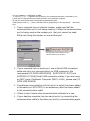
How to check
1.
View in the Device Manager Window.
For Windows XP or 2000
1.On the Desktop, right click on [My Computer] and click on [Properties].
2.In the System Properties Window, click on the [Hardware] Tab, then click on the
[Device Manager] button to view the Device Manager Window.
For Windows 98SE or ME
1.Open the [Control Panel] and double click on [System] to display the [System
Properties].
2.Click the [Device Manager] Tab to view the Device Manager Window.
2. In the [Device Manager], click on [Port (COM&LPT)] and check to
see if under that appears [Com Port (COM1)] or [Com Port (COM2)].
Other
62
- If a port appears, it should be usable.
- If a mark [ ! ] or [ × ] appears next to the port, this communication port is unusable. If you
cannot use a communication port please contact your computer company.
- To find out more details about an unusable communication port:
Select the port with a [ ! ] mark, and then click on [Properties] to view the details about that
port.
A : If your computer has an internal modem, make sure that the
communication port is not being used by it. When the communication
port is being used as the modem port, that port cannot be used.
Either quit using the modem or use another port.
An example of the modem using a
communication port (COM 1).
A : If your computer has no serial port, use a Serial-USB conversion
cable and carry out communication via USB connection. We
recommend [I.O DATA USB-RSAQ3] , [ELECOM UC-SGT] and
[IOGEAR UC-232A] Serial-USB conversion cables. If you are using
an NEC Lavie J Notebook Computer (NEC LJ-500), please use [I.O
DATA USB-RSAQ3].
A : Sometimes communication will not work if a switch has been added
to the serial port (RS-232C) or an extension cable has been added
to the communication cable.
A : Check to see if some other communication software is in use.
A : If your desktop computer has two serial ports, try connecting the
communication cable to the other port and try communicating again.
63
Other
Q : I can't get the communication cable connected to the computer.
What should I do?
A : Please connect the communication cable provided with the Thermo
Recorder into the serial port of your computer (D-SUB 9 pin male
connector). If for some reason you cannot connect directly, please
use an appropriate adapter (gender changer plug) as explained
below.
・ If the connector on your computer is a D-SUB 9 pin male then there is no need for an
adapter.
・ If the connector on your computer is a D-SUB 25 pin female then use an adapter (D-SUB 25
pin male to a D-SUB 9 pin male).
・ If the connector on your computer is a Half pitch 14 pin female then use the adapter (Half
pitch 14 pin male to a D-SUB 9 pin male) or a combination (Half pitch 14 pin male to D-SUB
25 pin male) and (D-SUB 25 pin female to a D-SUB 9 pin male).
Q: The date and the time of the recorded data are different from the
actual date and time of recording. Why?
A : The Thermo Recorder has no internal clock. When you set up a
programmed recording start or when you download data, the date
and time that are shown are taken form your computer's clock. If
your computer's clock is not correct, it will affect the recorded data.
A : When recording mode has been set to “Endless” and Recording
Start was carried out via PC, the time for recorded data is calculated
from the recording start date and time and will appear correctly in
the Graph as long as recording capacity has not reached its limit.
However, once data capacity has become full and the oldest data is
overwritten, the date and time for downloaded data in the Graph will
be calculated using the PC's clock for the latest recorded data and
subtracting backward. Hence the time for the displayed data will be
different from the actual time the data was recorded.
Other
64
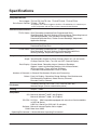
Specifications
Compatible Devices
Data Logger: TR-71U/TR-72U/TR-73U, TR-51S/TR-52S, TR-51A/TR-52
Data Comm. Devices TR-50U / TR-50C
*To properly use a Data Logger in the TR-5 / TR-5S Series, it is necessary to
use in conjunction with one of our Data Communication Devices.
CommunicationFunctions
TR-7U Series: Start Recording (Immediate Start/Programmed Start) ,
Stop Recording, Get Unit Settings (Channel Names, Recording Interval
and Recording Mode. also possible to make settings) ,
Download Recorded Data, Gather Current Readings, Adjustment,
Application Settings
TR-5 Series: Start Recording (Immediate Start / Programmed Start) ,
Download Recorded Data
TR-5S Series: Start Recording (Immediate Start / Programmed Start),
Stop Recording, Get Unit Settings, Download Recorded Data,
Warning Settings, Adjustment, Application Settings
Temp/Humidity Graph
Graph: Temp/Humidity Graphs for Each Channel (Zoom out / sin and scroll),
Change Channel Colors, Turn ON and OFF Channel Display
Data Display: Channel Name, Recording Interval, Number of Readings,
Highest / Lowest and Average Reading, Unit of Measurement,
AB Cursor Dates / Times and Data Readings,
Calculated Difference between Cursor A and B
Number of Channels: 8 Channel Simultaneous Display and Processing
Others: Data List Display, Calculation Range Settings, Data Maintenance,
Edit Recording Conditions, Delete Data by Channel,
Re-order Data by Channel
File Output
TR-Series Common Data Files (*.trx) / Text File (CSV, etc) ,
Selected Range: (File for selected time period)
Printing
Graphs / Tables
Compatible
OS: Microsoft Windows® 98SE / Me (English)
Microsoft Windows® 2000 / XP (English)
PC/CPU: PC/CPU: IBM Compatible equipped with more than Pentium 90MHz
or NEC 98 Series
USB Port / Serial Port (RS-232C D-sub 9pin)
Software: Microsoft Internet Explore 5.01or higher
RAM: More than 32MB
Operating Environment: A Stable Windows Operating Environment
65
Other
For product information or questions contact us at:
5652-169 Sasaga, Matsumoto, Nagano JAPAN 399-0033
Tel :+81-263-27-2131 Fax:+81-263-26-4281
E-mail:[email protected]
Office Hours: Monday to Friday 9:00-12:00 / 13:00-17:00(GMT +9:00 Tokyo Time)
[Home Page]
http://www.tandd.com/
We have opened an English Homepage called "T&D Online" for your
convenience. Here you can find information about our company, news,
products, upcoming events, software and user's Manual downloads, as well
as, other support. Please stop by and see what we have to offer.
T&D Recorder for Windows (TR-5,7xU)
User's Manual
Published by T&D CORPORATION
© Copyright 2002-2007 T&D Corporation. All rights reserved.
This is printed on recycled paper.