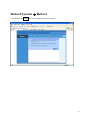
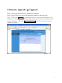
1
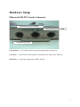
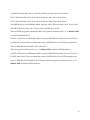
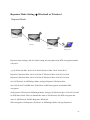
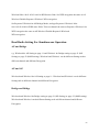
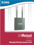
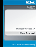
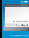
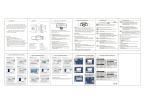
IEEE802.11a/g Dual Radio Mesh Wireless Outdoor Bridge User Manual Ver 1.1 WLO-2401AG Federal Communication Commission Interference Statement This equipment has been tested and found to comply with the limits for a Class B digital device, pursuant to Part 15 of the FCC Rules. These limits are designed to provide reasonable protection against harmful interference in a residential installation. This equipment generates, uses and can radiate radio frequency energy and, if not installed and used in accordance with the instructions, may cause harmful interference to radio communications. However, there is no guarantee that interference will not occur in a particular installation. If this equipment does cause harmful interference to radio or television reception, which can be determined by turning the equipment off and on, the user is encouraged to try to correct the interference by one of the following measures: - Reorient or relocate the receiving antenna. - Increase the separation between the equipment and receiver. - Connect the equipment into an outlet on a circuit different from that to which the receiver is connected. - Consult the dealer or an experienced radio/TV technician for help. This device complies with Part 15 of the FCC Rules. Operation is subject to the following two conditions: (1) This device may not cause harmful interference, and (2) this device must accept any interference received, including interference that may cause undesired operation. FCC Caution: Any changes or modifications not expressly approved by the party responsible for compliance could void the user's authority to operate this equipment. 2 IMPORTANT NOTE: FCC Radiation Exposure Statement: This equipment complies with FCC radiation exposure limits set forth for an uncontrolled environment. This equipment should be installed and operated with minimum distance 20cm between the radiator & your body. This transmitter must not be co-located or operating in conjunction with any other antenna or transmitter. 3 Table of Contents Table of Contents .......................................................................................................... 4 Package Contents .......................................................................................................... 6 Hardware Setup ............................................................................................................. 7 Ethernet & RS-232 Console Connector: ............................................................... 7 PSE BOX : for Power Over Ethernet (POE)......................................................... 8 Minimum System Requirements................................................................................... 9 Introduction ................................................................................................................... 9 Features and Benefits .......................................................................................... 13 Specification………………………………………………………………………….15 Four Operational Modes.............................................................................................. 17 AP Mode.............................................................................................................. 17 Repeater Mode .................................................................................................... 18 Point to Point Mode............................................................................................. 19 Point to Multi Point Mode................................................................................... 20 Using the Configuration Menu.................................................................................... 21 Device IP Setting Æ Ethernet ............................................................................. 24 Set Spanning Tree Protocol………………………………………………...27 AP Setting --> Wireless0 or Wireless1................................................................ 31 Encryption ........................................................................................................... 32 Set Encryption to Open System .................................................................. 48 Set Encryption to Shared Key ..................................................................... 49 Set Encryption to WPA-PSK..................................................................... 552 Set Encryption to WPA-Enterprise(802.1x) ................................................ 56 4 Point to Point Mode Setting Æ Wireless0 or Wireless1 ..................................... 59 Point to Multi Point Mode Setting Æ Wireless0 or Wireless1............................ 60 Repeater Mode Setting Æ Wireless0 or Wireless1 ........................................... 663 Dual Radio Setting For Simultaneous Operation................................................ 63 AP and Bridge ............................................................................................. 63 AP and AP ................................................................................................... 63 Bridge and Bridge ....................................................................................... 63 DHCP Server Setting Æ DHCP .................................................................................. 64 WAN Setting Æ WAN............................................................................................... 71 Firewall Setting Æ Firewall ........................................................................................ 76 Virtual Server setting Æ Virtual Server ...................................................................... 79 Static RouterÆStatic Router Configuration………………………………………….81 AdminÆAdmin Configuration……………………………………………………….87 Profiles………………………………………………………………………………..91 Status Æ Network Status........................................................................................... ..92 Connection Status…………………………………………………………………….93 Save & Check System Æ Save & Check……………………………………………..94 Reboot System Æ Reboot…………………………………………………………….95 Firmware upgrade Æ Upgrade.................................................................................... 96 Trouble Shooting……………………………………………………………………..97 Technical Specifications……………………………………………………………..101 5 Package Contents The standard package of the system includes: z Wireless-ABG Outdoor AP/Bridge x 1 z PSE BOX x 1 z Arrester x 2 z RF Cable x 2 z Ethernet cable x 2 z Console cable x 1 z AC Power cable x1 z Accessories package x1 z CD-ROM x 1 Note: Using a power supply with a different voltage than the one included with the Outdoor Bridge will cause damage and void the warranty for this product. 6 Hardware Setup Ethernet & RS-232 Console Connector: Ethernet RJ-45 Connector (LAN) Ethernet RJ-45 Connector (WAN) Console Port Connector Console Port --- It is used for initial setup and configuration of the device LAN Port --- It is used for connecting the enclosed PSE for Power Over Ethernet WAN Port --- It used for connecting to ADSL for ISP 7 PSE BOX : for Power Over Ethernet (POE) PSE BOX AC Power cable Power Over Ethernet : RJ-45 cable connecter PSE BOX (POWER &DATA OUT port) and Wireless-G Outdoor AP/Bridge WAN or LAN Ethernet Port Power LED Link Active LED 8 Minimum System Requirements Computers with Windows, Macintosh, or Linux-based operating systems with an installed Ethernet Adapter Internet Explorer version 6.0 or Netscape Navigator version 7.0 and above Introduction The Outdoor Bridge covers a large operating distance, providing an 802.11a/b/g outdoor WLAN which enables users to access the Internet or an organization’s network. At up to five times the speed of previous wireless devices, you can work faster and more efficiently, increasing productivity. With the Outdoor Bridge, bandwidth-intensive applications like graphics or multimedia will benefit significantly because large files are able to move across the network quickly. The Outdoor Bridge features a die-cast watertight housing and a built-in lightning protector to protect the access point from harsh environmental conditions, including extreme variance in temperature. It also includes Power over Ethernet (POE) and a unique outdoor remote-mounted design for easy installation. With two mounting kits, you have the option of either pole or wall mounting. The Outdoor Bridge is suitable for manufacturing plants, industrial sites, military bases, universities, hotels, airports and golf courses. The Outdoor Bridge has Dual Radio functionality for simultaneous AP and Bridge operations for backhaul applications. 9 Configurable in four different modes (access point, bridge, multi-point bridge, and wireless client), the Outdoor Bridge offers 128-bit encryption, WPA and 802.1X authentication when used with a RADIUS server, MAC address access control, and additional security features. Wireless Outdoor AP/Bridge are based on industry standards to provide easy-to-use and compatible high-speed wireless connectivity within your home, business or public access wireless networks. Wireless Outdoor AP/Bridge wireless products will allow you to access the data you want, when and where you want it. You will be able to enjoy the freedom that wireless networking brings.A Wireless Local Area Network (WLAN) is a computer network that transmits and receives data with radio signals instead of wires. WLANs are used increasingly in both home and office environments, and public areas such as airports, coffee shops and universities. Innovative ways to utilize WLAN technology are helping people to work and communicate more efficiently. Increased mobility and the absence of cabling and other fixed infrastructure have proven to be beneficial for many users. Wireless users can use the same applications they use on a wired network. Wireless adapter cards used on laptop and desktop systems support the same protocols as Ethernet adapter cards. People use WLAN technology for many different purposes: Mobility - Productivity increases when people have access to data in any location within the operating range of the WLAN. Management decisions based on real-time information can significantly improve worker efficiency. Low Implementation Costs - WLANs are easy to set up, manage, change and relocate. Networks that frequently change can benefit from WLANs ease of implementation. WLANs can operate in locations where installation of wiring may be impractical. Installation and Network Expansion - Installing a WLAN system can be fast and easy and can eliminate the need to pull cable through walls and ceilings. Wireless technology allows the network to go where wires cannot go - even outside the home or office. Inexpensive Solution - Wireless network devices are as competitively priced as conventional 10 Ethernet network devices. We can save money by providing multi-functionality, configurable in one of three different modes. Scalability - WLANs can be configured in a variety of ways to meet the needs of specific applications and installations. Configurations are easily changed and range from Peer-to-Peer networks suitable for a small number of users to larger Infrastructure networks to accommodate hundreds or thousands of users, depending on the number of wireless devices deployed. The Wireless Outdoor AP/Bridge Wireless Access Point utilizes the 802.11a, 802.11b and the 802.11g standards.The IEEE 802.11g standard is an extension of the 802.11b standard. It increases the maximum wireless signal rate of up to 54Mbps within the 2.4GHz band, utilizing OFDM technology.This means that in most environments, within the specified range of this device, you will be able to transfer large files quickly or even watch a movie in MPEG format over your network without noticeable delays. This technology works by transmitting high-speed digital data over a radio wave utilizing OFDM (Orthogonal Frequency Division Multiplexing) technology. OFDM works by splitting the radio signal into multiple smaller sub-signals that are then transmitted simultaneously at different frequencies to the receiver. OFDM reduces the amount of crosstalk (interference) in signal transmissions. The Wireless Outdoor AP/Bridge will automatically sense the best possible connection speed to ensure the greatest speed and range possible.The Wireless Outdoor AP/Bridge offers the most advanced network security features available today, including WPA and WPA2. In addition to its compatibility with 802.11g and 802.11a devices, the Wireless Outdoor AP/Bridge is compatible with 802.11b devices. This means that if you have an existing 802.11b network, or a network with a mixture of 802.11g, 802.11a and 802.11b, the devices in that network will be compatible with the Wireless Outdoor AP/Bridge. WPA-EAP is ideal for businesses that have existing security infrastructures in place. Management and security implementation can now be centralized on a server participating on 11 the network. Utilizing 802.1x with a RADIUS (Remote Authentication Dial-in User Service) server, a network adminstrator can define a list of authorized users who can access the wireless LAN. When attempting to access a wireless LAN with either WPA-EAP configured, the new client will be challenged with a username and password. If the new client is authorized by the administration, and enters the correct username and password, then access is granted. In a scenario where an employee leaves the company, the network administrator can remove the employee from the authorized list and not have to worry about the network being compromised by a former employee. 802.1x: Authentication which is a first line of defense against intrusion. In the authentication process, the Authentication Server verifies the identity of the client attempting to connect to the network. Unfamiliar clients would be denied access. EAP (Extensible Authentication Protocol) is available through the Windows XP Operating System. You will need to use the same type of EAP protocol on all the devices in your network when using the 802.1x feature. 12 Features and Benefits Features the benefit of Robust Outdoor Housing - Designed for harsh outdoor environments, with die-cast, watertight housing, built-in heater and temperature sensor High Performance Dual Radio usage for simultaneous operations of AP and Bridge for backhaul applications. The dual radio can be configures for AP and Bridge ; AP and AP ; Bridge and Bridge for various applications Features the benefits of repeating up to 10 MAC ID for each radio, therefore ability to repeat up to 20 MAC ID with dual radio functionality for great coverage and benefits 4 Different Operation modes with WDS (Wireless Distribution System) – Capable of operating in one of four different operation modes to meet your wireless networking requirements: access point (AP), Point-to-Point (PtP) bridge,Point-to-multipoint (PtMP) bridge, Repeater. Embedded DHCP Server automatically assigns IP addresses to wireless clients. Connect networks in different buildings when used in conjunction with high-gain outdoor antennas. Easy Installation with PoE. Compatible with IEEE802.11g standards to provide a wireless data rate of up to 54Mbps.* Backward compatible with the 802.11b standard to provide a wireless data rate of up to 11Mbps with 802.11b devices - that means you can migrate your system to the 802.11g standard on your own schedule without sacrificing connectivity. Better security with WPA and 802.1X- The Outdoor Bridge can securely connect to wireless clients on the network using WPA (Wi-Fi Protected Access) providing a much higher level of security for your data and communications than has previously been available. In conjunction with a RADIUS server, 802.1X authentication verifies the identity of would-be clients. 13 Communicate between IEEE802.11b and IEEE802.11g bands - Optional configuration allows communication between bands. Two mounting kits - Gives you the flexibility of either wall or pole outdoor mounting. 14 Specification Wireless Feature 7 Operation Modes : Wireless WAN ,Access Point, Repeater(WDS) ,Bridge, Client Bridge,Point-To-Point, Point-To-Multi-Point 802.11a and 802.11g wireless LANs can be used simultaneously High Speed data rate up to 54Mbps/108Mbps in “Turbo “ mode in 11g and 11a Hide SSID Boradcast (Site Survey Prevention) Denial Wireless 802.11abg “ANY” Station Handover users to other AP Multi country Roaming (802.11d) Bridging Feature 3 Way bridging for 802.3 and 802.a/g Scalable WDS (Wireless Distribution System) up to 10 Link Spanning Tree Back Up Wireless Security Feature Authentication 802.11i compliant WPA/PSK, WPA/Enterprise(802.1x) 802.1x supported Port Based network access(EAP-MD5/TLS) with Radius client (user authentication and accounting) EAP-PEAP and EAP-TLS , EAP-TTLS support 64/128- bit WEP encryption Protocol Filter MAC Access Control List PPPoE Authentication PAP/CHAP Encryption AES-CCMP encryption (WPA2) TKIP encryption enhancements : key hashing(per packet keying) , message integrity check(MIC) and broadcast key rotation via WPA TKIP Support for static and dynamic IEEE802.11 WEP keys of 64/128 bits VPN-Pass Through Zone Privacy for client to client blocking (User Isolation) Blocks client to client discovery within a specified VLAN for public Hotspots Management Change IP setting Change Password setting Firmware update 15 Load Default setting Remote Link Test a) Display WAN information b) Display Connect statics SNMP Traps to a list of IP number Adminstrative Access : Web browser (HTTP) Support SNMP v2c & v3 Support MIB II Support HTTP/WEB Support TFTP Monitoring and Diagonstics Remote Link Test Display WAN information Display Connect statistics SNMP Traps to a list of IP number Protocol IPV4 NetBIOS DHCP Client/Server IPX UDP ICMP RIP1 , RIP 2 PPPoE (Cleint) NAT/NAPT Built-in NAT firewall Virtual Server(NAT inbound server) Static Routing Internet Connection Detection 16 Four Operational Modes AP Mode AP Mode Wireless Eth WAN Port Internet Cable/ADSL Modem 17 Repeater Mode Repeater Mode Access Point Repeater1 Repeater2 Wireless Client 18 Point to Point Mode Point to Point (P2P : Wireless Bridge) Mode Wired Network Wired Network ADSL/Cable Modem LAN1 L2 Switch P2P-1 P2P-2 19 Point to Multi Point Mode PMP (Wireless Bridge) Mode Wired Network Wired Network ADSL/Cable Modem P2P-1 LAN1 Wired Network PMP P2P-2 20 Using the Configuration Menu To configure the Outdoor Bridge, use a computer which is connected to the Outdoor Bridge with an Ethernet cable (see the Network Layout diagram). First, disable the Access the Internet using a proxy server function. To disable this function, go to Control Panel > Internet Options > Connections > LAN Settings and uncheck the enable box. Start your web browser program (Internet Explorer, Netscape Navigator) . Type the IP address and http port of the Outdoor Bridge in the address field (http://192.168.2.254) and press Enter. Make sure that the IP addresses of the Outdoor Bridge and your computer are in the same subnet. After the connection is established, you will see the user identification window as shown. Note: If you have changed the default IP address assigned to the Outdoor Bridge, make sure to enter the correct IP address. 21 If you want to change setting, you will see the user identification window as shown. Type admin in the User Name field Type default the Password field blank Click OK 22 Note: If you have changed the password, make sure to enter the correct password. 23 Device IP Setting Æ Ethernet LAN is short for Local Area Network. This is considered your internal network. These are the IP settings of the LAN interface for the Outdoor Bridge. These settings may be referred to as private settings. You may change the LAN IP address if needed. IP address: The default IP address is 192.168.2.254. Assign a static IP address that is within the IP address range of your network. 24 IP Netmask: Enter the subnet mask. All devices in the network must share the same subnet mask.. 25 IP Gateway: Enter the IP address of the gateway in your network. (Note: If you change any item, click “submit” to store the value. Or click “clear” to restore previous value. To make settings working click Submit-> Reboot-> Reboot.) 26 Enable Spanning Tree Protocol: You can enable/disable the 802.1d STP (Spanning Tree Protocol) function on the bridge of WLAN and Ethernet (i.e. the LAN interface). Enable this function can detect loops in your LAN environment and then protect the LAN from being saturated with infinite loop traffic. 27 MAC Table Ageing Time: Determines the amount of time the root bridge stores protocol information received on an interface. 28 Hello Time: Determines how often the root bridge broadcasts hello messages to other bridge. 29 Forward Delay: Determines how long each of the listening and learning states last before the interface begins forwarding.(Maxmum:300 seconds) 30 AP Setting --> Wireless0 or Wireless1 Wireless Mode: Bridge/AP Bridge/WDS Routing/AP Routing/WDS or Disable Wireless. Select Bridge/AP if you want to set wireless in AP mode. 31 Encryption Mode: Disable/WEP/WPA-PSK/WPA-Enterpris if you want to set security in your network 32 Enable WMM(Wi-Fi Multimedia)extension WMM provides advanced quality of service (QoS) features for Wi-Fi networks to improve the end-user experience by prioritizing audio, video and voice traffic and optimizing the way shared network resources are allocated among competing applications. 33 ESSID: Service Set Identifier (SSID) is the name designated for a specific wireless local area network (WLAN). The SSID’s factory default setting is DDA. The SSID can be easily changed to connect to an existing wireless network or to establish a new wireless network. 34 Hidden SSID: Enable or Disable SSID broadcast. Pull down select “y” Disable SSID broadcast or “n” Enable SSID broadcast. Disable this feature broadcasts the SSID across the network. 35 Client Isolation: Pull down “y” isolation or “n” none isolation 36 Band Mode: You can select 802.11a for 5.180-5.825GHz Band, 802.11b/g for 2.4Ghz Band 37 Enable Pure G: Pull down “√” to enable pure G 38 Enable Super AG: Pull down “√” to enable super AG 39 Transmit Rate Control: The value are Auto, 1Mbps, 2Mbps, 5.5Mbps, 6Mbps, 9Mbps,11Mbps, 12Mbps, 18Mbps, 24Mbps, 36Mbps, 48Mbps, 54Mbps. 40 Country: You can select US for channel 1~11, ETSI for channel 1~13, Japan for channel 1~14. 41 Channel: You can select blow (US: Channel 1 ~ 11, ETSI: Channel 1 ~13, Japan: Channel 1 ~ 14 ) (Note: Channel 14 only 802.11b mode). All devices on the network must share the same channel. (Note: The wireless adapters will automatically scan and match the wireless setting.) 42 Output Power: You can select 1~100 to control the output power level 43 Slot time: Slot time is a concept in computer networking. It is the time it takes for an electronic pulse Physical Layer to travel the length of the maximum theoretical distance between two nodes. 44 Encryption The Outdoor Bridge has the newest, strongest and most advanced security features available today. When used with other 802.11 WPA (Wi-Fi Protected Access) compatible products in a network with a RADIUS server, the security features include: WPA & 802.1x represent the first line of defense against network intrusion. In the authentication process the RADIUS server verifies the identity of the client attempting to connect to the network. Unfamiliar clients will be denied access. EAP(Extensible Authentication Protocol) is available through the Windows XP Operating System. You will need to use the same type of EAP protocol on all the devices in your network when using the 802.1x feature. WPA (Wi-Fi Protected Access) authorizes and identifies users based on a secret key that changes automatically at regular intervals. WPA uses TKIP (Temporal Key Integrity Protocol) to change the temporal key every 10,000 packets (a packet is a kind of message transmitted over a network.) This ensures much greater security than the standard WEP security. (By contrast, the previous WEP encryption implementations required the keys to be changed manually.) WPA-PSK allows home users that will not incorporate a RADIUS server in their network, access to WPA security. Utilizing the Pre-Shared Key mode of WPA, the Outdoor Bridge will obtain a new security key every time it connects to the 802.11 network. You only need to input your encryption information once in the configuration menu. No longer will you have to manually input a new WEP key frequently to ensure security. With the Outdoor Bridge and WPA-PSK, you will automatically receive a new key every time you connect, vastly 45 increasing the safety of your communication. 46 47 Set Encryption to Open System WEP mode: Select 64, 128 bits. WEP auth method: Select Open System to communicate the key across the network. Passphrase: 64 bit support WEP password 10 bit HEX(Hexadecimal digits consist or the numbers 0-9 and the letters A-F) code. 128 bit support WEP password 26 bit HEX code.( Note :Currently version does not support ASCII code.) WEP Key1 : Enter up encryption keys here. WEP Key2 : Enter up encryption keys here. WEP Key3 : Enter up encryption keys here. WEP Key4 : Enter up encryption keys here. 48 49 Set Encryption to Shared Key WEP mode: Select 64, 128 bits WEP auth method: Select Shared Key to communicate the key across the network.. 50 Passphrase: 64 bit support WEP password 10 bit HEX(Hexadecimal digits consist or the numbers 0-9 and the letters A-F) code. 128 bit support WEP password 26 bit HEX code.( Note :Currently version does not support ASCII code.) WEP Key1 : Enter up encryption keys here. WEP Key2 : Enter up encryption keys here. WEP Key3 : Enter up encryption keys here. WEP Key4 : Enter up encryption keys here. 51 Set Encryption to WPA-PSK WPA Mode: When you select WPA-PSK, you must select AES or TKIP from the pull-down menu. 52 Group rekey interval: Select the interval during which the group key will be valid. 53 Master rekey interval: Select the interval during which the master key will be valid. 54 ASCII: Enter a passphrase. The passphrase is a password between 8 and 63 characters long. The password can include symbols (!?*&_) and spaces. Make sure you enter this key exactly the same on all other wireless clients. 55 Hex: Enter a passphrase. The passphrase is a password only 64 Hex characters 56 Set Encryption to WPA-Enterprise (802.1x) Authentication Server: Enter the IP address of the RADIUS server. 57 Port: The port number your RADIUS server uses for authentication. The default setting is 1812 58 Shared Key: This is used by your RADIUS server in the Shared Secret field in RADIUS protocol messages. The shared secret configured in the Wireless Outdoor AP/Bridge must match the shared secret configured in the RADIUS server. The shared secret can contain up to 64 alphanumeric characters. (Note: If you change any item, click “submit” to store the value. Or click “clear” to restore previous value. To make settings working click Submit-> Reset-> Restart.) 59 Point to Point Mode Setting Æ Wireless0 or Wireless1 Point to Point (P2P : Wireless Bridge) Mode Wired Network Wired Network LAN2 LAN1 L2 Switch L2 Switch P2P-1 P2P-2 PtP mode setting is like AP mode setting, but encryption only WEP encryption method can select. When wireless0 or wireless1 in PtP mode will also do AP function, suggest disable SSID broadcast(Pull down select “y” in hidden SSID to disable SSID broadcast) and set WEP encryption. e.g. P2P-1 Wireless0 Mac: 00.01.02.03.04.05 Wireless1 Mac: 00.01.02.03.04.06 P2P-2 Wireless0 Mac: 00.01.02.03.04.07 Wireless1 Mac: 00.01.02.03.04.08 Set P2P-1 Wireless 1 in AP/Bridege Mode, and type P2P-2 Wireless1 Mac: 00.01.02.03.04.08 in WDS macs fields. Then set WEP encryption, and disable WPA encryption. Pull down select “y” in hidden SSID to disable SSID broadcast. 60 Set P2P-2 Wireless1 in AP/Bridege Mode, and type P2P-1 Wireless1 Mac: 00.01.02.03.04.06 in WDS macs fields. Then set channel the same as P2P-1 Wireless1.Set WEP encryption the same as P2P-1 Wireless1.Dsiable P2P-2 Wireless1 WPA encryption. Pull down select “y” in hidden SSID to disable SSID broadcast. Point to Multi Point Mode Setting Æ Wireless0 or Wireless1 PMP ( Wireless Bridge) Mode Wired Network LAN2 L2 Switch Wired Network P2P-1 LAN1 Wired Network PMP LAN3 P2P-2 L2 Switch PtMP mode setting is like AP mode setting, but encryption only WEP encryption method can select. When wireless0 or wireless1 in PtMP mode will also do AP function, suggest disable SSID broadcast(Pull down select “y” in hidden SSID to disable SSID broadcast) and set WEP encryption. 61 e.g PMP Wireless0 Mac: 00.01.02.03.04.05 Wireless1 Mac: 00.01.02.03.04.06 P2P-1 Wireless0 Mac: 00.01.02.03.04.07 Wireless1 Mac: 00.01.02.03.04.08 P2P-2 Wireless0 Mac: 00.01.02.03.04.09 Wireless1 Mac: 00.01.02.03.04.0A Set PMP Wireless1 in AP/Bridege Mode, and type P2P-1 Wireless1 Mac: 00.01.02.03.04.08 and P2P-2 Wireless1 Mac: 00.01.02.03.04.0A in WDS macs fields. Then set WEP encryption, and disable WPA encryption. Pull down select “y” in hidden SSID to disable SSID broadcast. Set P2P-1 Wireless1 in AP/Bridege Mode, and type PMP Wireless1 Mac: 00.01.02.03.04.06 in WDS macs fields. Then set channel the same as PMP Wireless1.Set WEP encryption the same as PMP Wireless1.Dsiable P2P-1 Wireless1 WPA encryption. Pull down select “y” in hidden SSID to disable SSID broadcast. Set P2P-2 Wireless1 in AP/Bridege Mode, and type PMP Wireless1 Mac: 00.01.02.03.04.06 in WDS macs fields. Then set channel the same as PMP Wireless1.Set WEP encryption the same as PMP Wireless1.Dsiable P2P-2 Wireless1 WPA encryption. Pull down select “y” in hidden SSID to disable SSID broadcast. 62 Repeater Mode Setting Æ Wireless0 or Wireless1 Repeater Mode Access Point Repeater1 Repeater2 Wireless Client Repeater mode setting is like AP mode setting, but encryption only WEP encryption method can select. e.g AP Wireless0 Mac: 00.01.02.03.04.05 Wireless1 Mac: 00.01.02.03.04.06 Repeater1 Wireless0 Mac: 00.01.02.03.04.07 Wireless1 Mac: 00.01.02.03.04.08 Repeater2 Wireless0 Mac: 00.01.02.03.04.09 Wireless1 Mac: 00.01.02.03.04.0A Set AP Wireless1 in AP/Bridege Mode, and type Repeater1 Wireless0 Mac: 00.01.02.03.04.07 in WDS macs fields.Then set WEP encryption, and disable WPA encryption. Set Repeater1 Wireless0 in AP/Bridege Mode, and type AP Wireless1 Mac: 00.01.02.03.04.06 in WDS macs fields. Then set channel the same as AP Wireless1.Set WEP encryption the same as AP Wireless1.Dsiable Repeater1 Wireless0 WPA encryption. Set Repeater1 Wireless1 in AP/Bridege Mode, and type Repeater2 63 Wireless0 Mac: 00.01.02.03.04.09 in WDS macs fields. Set WEP encryption the same as AP Wireless1.Dsiable Repeater1 Wireless1 WPA encryption. Set Repeater2 Wireless0 in AP/Bridege Mode, and type Repeater1 Wireless1 Mac: 00.01.02.03.04.08 in WDS macs fields. Then set channel the same as Repeater1 Wireless1.Set WEP encryption the same as AP Wireless1.Dsiable Repeater2 Wireless0 WPA encryption. Dual Radio Setting For Simultaneous Operation AP and Bridge e.g. Wireless0 do AP Setting as page 11 and Wireless1 do Bridge setting as page 21 (PtP Setting) or page 22 (PtMP setting). Wireless0 and Wireless1 can do different Setting such as different channel and different Encryption AP and AP Wireless0 and Wireless1 do AP Setting as page 11. Wireless0 and Wireless1 can do different Setting such as different channel and different Encryption. Bridge and Bridge Wireless0 and Wireless1 do Bridge setting as page 21 (PtP Setting) or page 22 (PtMP setting). Wireless0 and Wireless1 can do different Setting such as different channel and different Encryption 64 DHCP Server Setting Æ DHCP DHCP Server Control: Dynamic Host Configuration Protocol assigns dynamic IP addresses to devices on the network. This protocol simplifies network management and allows new wireless devices to receive IP addresses automatically without the need to manually assign new IP addresses. Subnet : Select Subnet on device IP(Such as 192.168.2.254) to allow the Outdoor Bridge to function as a DHCP server. 65 Start IP: Input the first IP address available for assignment in your network. 66 End IP: Input the end IP address available for assignment in your network. 67 Router: Input device IP 68 DNS: Input your ISP DNS. 69 WINS: Input wins server IP 70 DHCP Clients list: Show the client IP and client MAC setting. (e.g. If your device ip is 192.168.2.254, then start ip is 10 and end ip is 100. System will asign ip from 192.168.2.10 to 192.168.2.100 to client.) (Note: If you change any item, click “submit” to store the value. Or click “clear” to restore previous value. To make settings working click Submit-> Reset-> Restart.) 71 WAN Setting Æ WAN To select the connection type for WAN port you can choose any of the following Mode: For static IP,: please click Static IP and type IP address, IP netmask, IP gateway 72 For dynamic IP: Please click the Dynamic IP and type Hostname 73 For PPPoE: For xDSL and using PPPoE to connect to Internet, please click PPPoE and type username and password. 74 • For LAN Backup: The two LAN ports provide failover support a backup operation that automatically 75 • For Disable WAN Port: Please click Disable. (Note: If you change any item, click “submit” to store the value. Or click “clear” to restore previous value. To make settings working click Submit-> Reset-> Restart.) 76 Firewall setting Æ Firewall IP Rules: Once a choice is made, the choice applies to all filtering rules. To define/add an IP filtering rule, enter the following information Source: Address/Mask: you must define Single IP and subnet mask of source IP addresses. Port: you must define one port numbers. 77 Destination: Address/Mask: you must define single IP and submask of destination IP addresses. Port: you must define one port numbers. 78 MAC Rules: fields you can control 20 MACs which can pass connect to system or deny from system. (Note: If you change any item, click “submit” to store the value. Or click “clear” to restore previous value. To make settings working click Submit-> Reset-> Restart.) 79 Virtual Server setting Æ Virtual Server A Virtual Server is a server built on a single or a cluster of real servers. A server is a term commonly used to describe the default Virtual Server - the router will redirect all traffic from the Internet without a valid port address mapping to this device. An HTTP server with a private IP address on the LAN allows access from the Internet by mapping a special port to the HTTP server. In this case, the HTTP service will be mapped to a special port of the Router. You can add a virtual server mapping by (1) decription of the service name (such as HTTP, FTP,TELNET, SMTP, POP3, CUSTOM), (2) enter the public port number to be used (either a single port number), (3)enter the Local IP address(Private) of the server on your LAN, (4)enter its local port number to map(5) choose tcp protocol or udp protocol You can define 10 groups Virtual Server here. e.g. If you build a Server at local PC(client) and Wireless-G Outdoor AP/Bridge is connect to internet have a real IP. Check Enable the rule in Virtual Server and type Description, then key-in local PC’s IP in Local IP fields and port(use by the Server) in Local Port and select protocol (use by the Server). After finish those setting click Submit-> Reset-> Restart restart system to make settings work. The Server build at local PC will work in internet. 80 81 Static RouterÆStatic Router Configuration Routing Table: The Routing Table shows a list of destinations that the IP software maintains on each host and router. The destination network IP address, subnet mask, gateway address, and the corresponding interface are displayed. Enable: If you want to enable routing protocol, pull down “√” to enable routing protocol. 82 Dest Net: Enter the IP address of the destination network in the Dest Net field. 83 Mask: Enter the subnet in the Subnet Mask field. 84 Gateway: Enter the IP address of the specific router in the Gateway IP Address field. 85 Device: Select Ethernet、Wireless0、Wireless1 orWAN, where is the specific router is, from the Interface menu. 86 OSPF can be enabled to consolidate multiple routes into one single advertisement and hence reduce the routing database make routing simpler and faster. When this function is enabled, it will only be effective when the Wireless Outdoor AP/Bridge is an area border rouer, that is,at least two OSPF enabled interface are configured with different Router IDs. For each summarization entry, you have to enter the Router ID such that routes from the Area falling into the specified subnet (IP address/Netmask) will be summarized into a single route to the specified subnet and it is the single route instead of the individual route to be injected into other Areas. When OSPF is selected. You can select the interface (Ethernet、Wireless0、Wireless1 orWAN) to run OSPF.For each interface where OSPF is enabled, you have to configure the Area that the interface belongs to by specifying the RouterID, and the priority of the Wireless Outdoor AP/Bridge on the segment the interface belongs to. Also, for the segment that an OSPF enabled interface, you have to configure the Hello interval and Dead interval on the segment,the Cost for transmitting a packet on the segment. 87 AdminÆAdmin Configuration Set New Admin Password: The default factory password is “default”. If want to change the password,enter the new password. 88 Type New Password Again: Followed by the new password twice. The entered characters will appear as asterisks. 89 SNMP: Choose v2c or v3 version 90 Enable SNMP Trap: A trap manager is a remote SNMP management station where special SNMP trap messages are generated (by the Access Point) and sent to in the network. 91 Profiles Load Setting From PC: In this page, you can save your current configuration, restore a previously saved configuration, or restore all of the settings in the router to the factory (default) settings. 92 Status Æ Network Status When WAN setting is Static IP click Status/Network Status will show current IP status. You can click renew or release to renew or release IP at Dynamic IP setting, and click disconnect or connect to disconnect or connect your ISP at PPPoE setting. 93 Save & Check System Æ Save & Check Click Save & Check Æ It will store settings and check system. 94 Reboot System Æ Reboot Click Reboot Æ Restart will store settings and restart system. 95 Firmware upgrade Æ Upgrade Step 1 : Set your PC IP (192.168.2.X), and close PC’s firewall. Step 2 : Open a TFTP server on your PC and put the firmware in the same direct. Step 3 : Click on the Upgrade tab and then the main screen enter the PC IP address in the “tftp server :”field section 192.168.2.X , and the second option “file name” please key in the firmware file name. Then click Download and reset. It may take a up to 2 min for the upgrade to complete. 96 Trouble Shooting 1.This Chapter provides solutions to problems that can occur during the installation and operation of the Wireless Outdoor AP/Bridge Wireless Access Point. We cover various aspects of the network setup, including the network adapters. Please read the following if you are having problems. Note: It is recommended that you use an Ethernet connection to configure the Wireless Outdoor AP/Bridge Wireless Access Point. The computer used to configure the Wireless Outdoor AP/Bridge cannot access the Configuration menu. Check that the Ethernet LED on the Wireless Outdoor AP/Bridge is ON. If the LED is not ON, check that the cable for the Ethernet connection is securely inserted. Check that the Ethernet Adapter is working properly. Please see item 3 (Check that the drivers for the network adapters are installed properly) in this Troubleshooting section to check that the drivers are loaded properly. Check that the IP address is in the same range and subnet as the Wireless Outdoor AP/Bridge. Please see Checking the IP Address in Windows XP in the Networking Basics section of this manual. Note: The IP address of the Wireless Outdoor AP/Bridge is 192.168.2.254. All the computers on the network must have a unique IP address in the same range, e.g., 192.168.2.x. Any computers that have identical IP addresses will not be visible on the network. They must all have the same subnet mask, e.g., 255.255.255.0. Do a Ping test to make sure that the Wireless Outdoor AP/Bridge is responding. Go to Start>Run>Type Command>Type ping 192.168.2.254. A successful ping will show four replies. Note: If you have changed the default IP address, make sure to ping the correct IP address assigned to the Wireless Outdoor AP/Bridge. 97 2. The wireless client cannot access the Internet in the Infrastructure mode. Make sure the wireless client is associated and joined with the correct access point,and please make sure you have selected the correct available network, as shown in the illustrations below. Check that the IP address assigned to the wireless adapter is within the same IP address range as the access point and gateway. Since the Wireless Outdoor AP/Bridge has an IP address of 192.168.2.254, wireless adapters must have an IP address in the same range, e.g., 192.168.2.x. Each device must have a unique IP address; no two devices may have the same IP address. The subnet mask must be the same for all the computers on the network.) To check the IP address assigned to the wireless adapter, double-click on the Local Area Connection icon in the taskbar > select the Support tab and the IP address will be displayed. Please refer to Checking the IP Address in the Networking Basics section of this manual.) If it is necessary to assign a Static IP Address to the wireless adapter, please refer to the appropriate section in Networking Basics. If you are entering a DNS Server address you must also enter the Default Gateway Address. (Remember that if you have a DHCP-capable router, you will not need to 98 assign a static IP address. See Networking Basics: Assigning a Static IP Address.) 3. What variables may cause my wireless products to lose reception? Wireless outdoor products let you access your network from virtually anywhere you want. However, the positioning of the products within your environment will affect the wireless range. Please refer to Installation Considerations in the Wireless Basics section of this manual for further information about the most advantageous placement of your wireless products. 4. Why does my wireless connection keep dropping? Antenna Orientation- Try different antenna orientations for the Wireless Outdoor AP/Bridge. Try to keep the antenna at least 6 inches away from the wall or other objects. If you are using 2.4GHz cordless phones, other home security systems, ceiling fans, and lights, your wireless connection will degrade dramatically or drop altogether. Try changing the channel on your router, access point and wireless adapter to a different channel to avoid interference.Keep your product away (at least 3-6 feet) from electrical devices that generate RF noise, like microwaves, monitors, electric motors, etc. 5. Why can’t I get a wireless connection? If you have enabled encryption on the Wireless Outdoor AP/Bridge, you must also enable encryption on all wireless clients in order to establish a wireless connection. Make sure that the SSID on the router and the wireless client are exactly the same. If they are not, wireless connection will not be established. Move the Wireless Outdoor AP/Bridge and the wireless client into the same room and then test the wireless connection. Disable all security settings. Turn off your Wireless Outdoor AP/Bridge and the client. Turn the Wireless Outdoor AP/Bridge back on again, and then turn on the client. Make sure that all devices are set to Infrastructure mode. 99 Check that the LED indicators are indicating normal activity. If not, check that the AC power and Ethernet cables are firmly connected. Check that the IP address, subnet mask, gateway and DNS settings are correctly entered for the network. If you are using 2.4GHz cordless phones, other home security systems, ceiling fans, and lights, your wireless connection will degrade dramatically or drop altogether. Try changing the channel on your Wireless Outdoor AP/Bridge, and on all the devices in your network to avoid interference. Keep your product away (at least 3-6 feet) from electrical devices that generate RF noise, like microwaves, monitors, electric motors, etc. 100 Technical Specifications Standards • IEEE 802.11a • IEEE 802.11b • IEEE 802.11g • IEEE 802.3 • IEEE 802.3u • IEEE 802.3x Device Management • Web-Based – Internet Explorer v6 or later; Netscape Navigator v7 or later; or other Java-enabled browsers. • SNMP v.2c • SNMP v.3 Data Rate For 802.11a/g :• 54, 48, 36, 24, 18, 12, 9 and 6Mbps For 802.11b: • 11, 5.5, 2, and 1Mbps Security • WPA • WPA2 • 64/128bit WEP • SSID Broadcast Disable Wireless Frequency Range • 2.4GHz to 2.4835GHz • 5.180GHz to 5.825GHz Wireless Operating Range *802.11a/g Indoors: • 98ft (30m) @ 54Mbps • 112ft (34m) @ 48Mbps • 128ft (39m) @ 36Mbps • 154ft (47m) @ 24Mbps • 184ft (56m) @ 18Mbps • 217ft (66m) @ 12Mbps • 259ft (79m) @ 9Mbps • 325ft (99m) @ 6Mbps 101 Outdoors: • 367ft (112m) @ 54Mbps • 820ft (250m) @ 18Mbps • 1640ft (500m) @ 6Mbps Operating Voltage • 48VDC +/- 10% for PoE Radio and Modulation Type For 802.11b:DSSS: • DBPSK @ 1Mbps • DQPSK @ 2Mbps • CCK @ 5.5 and 11Mbps For 802.11a/g: OFDM: • BPSK @ 6 and 9Mbps • QPSK @ 12 and 18Mbps • 16QAM @ 24 and 36Mbps • 64QAM @ 48, 54 Mbps DSSS: • DBPSK @ 1Mbps • DQPSK @ 2Mbps • CCK @ 5.5 and 11Mbps Transmit Output Power For 802.11a: • 100mW (20dBm) • 50mW (17dBm) • 30mW (15dBm) • 20mW (13dBm) • 10mW (10dBm) • 5mW (7dBm) • 1mW (0dBm) For 802.11b: • 200mW (23dBm) • 63mW (18dBm) • 30mW (15dBm) • 20mW (13dBm) • 10mW (10dBm) • 5mW (7dBm) 102 • 1mW (0dBm) For 802.11g: • 200mW (23dBm) • 63mW (18dBm) • 30mW (15dBm) • 20mW (13dBm) • 10mW (10dBm) • 5mW (7dBm) • 1mW (0dBm) Receiver Sensitivity For 802.11a: • 6Mbps: -85dBm • 9Mbps: -84dBm • 12Mbps: -82dBm • 18Mbps: -80dBm • 24Mbps: -77dBm • 36Mbps: -73dBm • 48Mbps: -69dBm • 54Mbps: -68dBm For 802.11b: • 1Mbps: -94dBm • 2Mbps: -91dBm • 5.5Mbps: -89dBm • 11Mbps: -85dBm For 802.11g: • 1Mbps: -95dBm • 2Mbps: -91dBm • 5.5Mbps: -89dBm • 6Mbps: -90dBm • 9Mbps: -84dBm • 11Mbps: -88dBm • 12Mbps: -82dBm • 18Mbps: -80dBm • 24Mbps: -77dBm • 36Mbps: -73dBm • 48Mbps: -72dBm • 54Mbps: -72dBm 103 LEDs • Power • Active Temperature • Operating: -40ºF to 140ºF (-40ºC to 60ºC) • Storing: -40ºF to 149ºF (-40ºC to 65ºC)Humidity • Operating: 10%~90% (non-condensing) • Storing: 5%~95% (non-condensing)Certifications Warranty• 1 Year 104