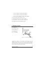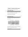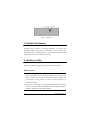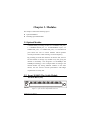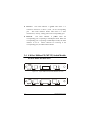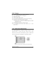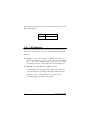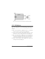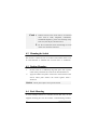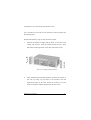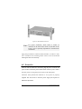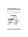
1
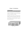
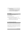
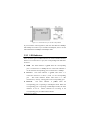
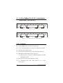
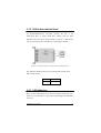
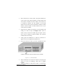
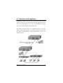
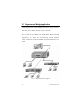
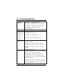
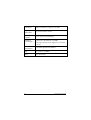
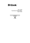
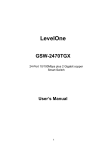
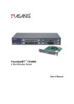
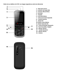
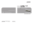
Table of Content CHAPTER 1. INTRODUCTION ...................................................1 1-1 About the Switch.................................................................1 1-2 Feature ...............................................................................2 1-3 Package Contents...............................................................3 CHAPTER 2. HARDWARE DESCRIPTION...............................5 2-1 Physical Description ..........................................................5 2-2 Front & Rear Panel............................................................5 2-3 Module LED Indicators......................................................6 2-4 Dual Power LEDs ..............................................................6 CHAPTER 3. MODULES...............................................................7 3-1 Optional Modules...............................................................7 3-2 8-port 10/100 N-Way Switch Module ..............................7 3-2-1 Features: ......................................................................8 3-2-2 DIP-Switch with Link Mode.........................................8 3-2-3 LED Indicators ............................................................9 3-3 2/4-Port 100Base-FX( SC/ST ) Switch Module .............10 3-3-1 Features: ....................................................................10 3-3-2 DIP-Switch with Link Mode....................................... 11 3-3-3 LED Indicators .......................................................... 11 3-4 4/ 8-Port 100Base-FX (MT/VF) Switch Module ...........12 3-4-1 Features .....................................................................13 3-4-2 DIP-Switch with Link Mode.......................................13 3-4-3 LED Indicators ..........................................................14 3-5 Gigabit 1000Base-SX/LX Switch Modules ....................15 3-5-1 Features .....................................................................15 3-5-2 DIP Switch with Link Mode .......................................15 3-5-3 LED Indicators ..........................................................16 3-6 Gigabit 10/100/1000Base-T Switch Module .................17 3-6-1 Features .....................................................................17 3-6-2 LED Indicators ..........................................................18 3-6-3 Installing Optional Modules ......................................18 CHAPTER 4. INSTALLATION ...................................................21 4-1 Pre-Installation Requirements.......................................21 4-2 Mounting the Switch......................................................22 4-3 Desktop Mounting .........................................................22 4-4 Rack Mounting ..............................................................22 4-5 Power On ......................................................................24 CHAPTER 5. PLANNING YOUR NETWORK .........................25 5-1 Modularized Switch Application ...................................26 5-2 Backbone Switch Application........................................27 5-3 Departmental Bridge Application .................................28 5-4 Technical Specifications ................................................29 Trademarks Copyright PLANET Technology Corp. 2001. Contents subject to revision without prior notice. PLANET is a registered trademark of PLANET Technology Corp. All other trademarks belong to their respective owners. FCC Warning This equipment has been tested and found to comply with the limits for a Class A digital device, pursuant to Part 15 of the FCC Rules. These limits are designed to provide reasonable protection against harmful interference when the equipment is operated in a commercial environment. This equipment generates, uses, and can radiate radio frequency energy and, if not installed and used in accordance with the Instruction manual, may cause harmful interference to radio communications. Operation of this equipment in a residential area is likely to cause harmful interference in which case the user will be required to correct the interference at his own expense. Reversion PLANET Gigabit Chassis Switch User's Manual FOR MODELS: FGSW-008 Part No.: EMFGSW08V1 Chapter 1. Introduction 1-1 About the Switch Congratulations on purchasing the Chassis Switch FGSW-008. The Switch is a combination of 8 slot host cabinet which can optional a lot of kinds of media modules to fit your networking needs. A maximum 64X 10/100 Base-TX switched ports can be achieved using 8X 8 port 10/100Base-TX switch module. By providing 8 G-Link bus interfaces in the base unit, the user has the freedom to arrange any module in any slot giving the ultimate in flexibility. Switch features store-and-forward switching scheme. Every module has its own 12K-entry MAC address to store source address. The backplane of the Switch can reach up to 19.2Gbps as to improving network performance. Figure 1-1. The Switch This chapter gives an overview of the Switch and it covers the following items: n About the switch n Features n Package contents 1-2 Feature The 8-expansion slots can flexible configure your network. It can be 64 ports 10/100Base-TX switch, 32 ports 100Base-FX(SC/ST) switch, 64 ports 100Base-FX(MT-RJ/VF-45) switch or 8 ports Gigabit Switch. Redundant Hot-Swap power supply support. Install our Gigabit Module and say goodbye to data bottlenecks. The Gigabit Module catapults your 10 and 100Mbps signals to a full 1000Mbps for unparalleled uplink data capacity. The Switch has following features: n Conforms to the IEEE 802.3, 802.3u, 802.3z & 802.3x, 802.3ab standards n 8 expansion slots n Support different optional modules include: 8-port 10/100Base-TX N-way Switch Module 2-port 100Base-FX Fiber Module ( ST/SC/MT-RJ/VF-45 ) 4-port 100Base-FX Fiber Module ( ST/SC/MT-RJ/VF-45 ) 8- port 100Base-FX Fiber Module ( MT-RJ/VF-45 ) 2 Gigabit Chassis Switch one-port 1000Base-SX Gigabit Fiber Module one-port 1000Base-LX Gigabit Fiber Module one-port 10/100/1000Base-T Gigabit copper Module n Store-and-Forward technology is used n Redundant Hot Swap Power Supply support n Plug-and-Play, self-learns network configuration n Supports both half and full-duplex modes 1-3 Package Contents n The Switch n One Power Cord n Rack-Mount Kit n 4 Rubber Feet n User’s Manual Figure1-2. The Package contents of Switch Compare the contents of your FGSW switch package with the standard checklist above. If any item is missing or appears damaged, please keep the carton and original packaging materials if possible in case you need to return the switch for repair. FGSW-008 User's Manual 3 This page is intentionally left blank 4 Gigabit Chassis Switch Chapter 2. Hardware Description This chapter mainly describes the hardware of the Switch: 2-1 Physical Description The Switch is a modular unit, and its chassis contains 8 expansions. The LEDs are located on the front panel of the Switch to allow you to monitor the operation and performance at a glance. The Physical Dimensions of the Switch are: 440mmX 266mmX 133mm (3U height) 2-2 Front & Rear Panel The front panel of Switch displayed in Figure 2-1 is shown with 8-port 10/100Base-TX Modules, 100Base-FX Modules and Fiber Gigabit Modules. Figure 2-1. Front Panel The 3-pronged power plug and On/off switched are located at the Rear Panel of the Switch displayed in Figure 2-2. The Switch will work with AC in the range 100-240VAC, 50-60Hz. FGSW-008 User's Manual 5 Figure 2-2. Rear Panel 2-3 Module LED Indicators All LED status indicators are located on the FRONT panel of the switches. They provide a real-time indication of system and operational status. The ports for connections to other devices and networks are also on the front panels. The following sections provide descriptions of the LED indicators and ports. 2-4 Dual Power LEDs There are four LEDs located on the front panel of the Switch. The LEDs are to indicate dual power supply status (Good or Fail ). Power Notice: 1. The device is a power-required device, it means, it will not work till it is powered. If your networks should active all the time, please consider use an UPS (Uninterrupted Power Supply) for your device. It will prevent you from network data loss or network downtime. 2. In some area, installing a surge suppression device may also help to protect your hub from being damaged by unregulated surge or current to the Switch or the power adapter. 6 Gigabit Chassis Switch Chapter 3. Modules This chapter contains the following topics: n Optional Modules n Installing Optional Modules 3-1 Optional Modules A module family consisting of either 8 x 10/100Base-TX ports; 1 x 1000Base-SX/LX port, 1 x 10/100/1000Base-T port, 2 x 100Base-FX ports; 4 x 100Base-FX ports, 8 x 100 Base-FX ports allows the user to choose modules which optimize network performance while reducing cost and complexity. By providing 8 G-Link bus interfaces in the base unit, the user has the freedom to arrange any module in any slot giving the ultimate in flexibility. The integration of 10/100Mbps and 1000Mbps technology is now a simple matter of slotting in the desired module. By mixing different modules in the same cabinet, the user ensures network performance and budget requirements are easily met. 3-2 8-port 10/100 N-Way Switch Module FGSW-8TP(V.x) Figure 3-1. 8-port 10/100 N-Way Module Front View FGSW-008 User's Manual 7 Note: Please make sure the version of the module before slide-in it to the slot. Use of module FGSW-8TP could cause LED indication abnormal in FGSW-008. The accepted one is version 2 or above. The version number can be found besides the serial number with format: FGSW-8TP (V.x). 3-2-1 Features: n 8X10/100Mbps N-Way auto-negotiation switch ports n Up to 2.4Gbps Backplane forwarding rate n 2MB memory buffer n 12K-entry MAC Address Table n Store-and-forward technology for abnormal packet filtering n Half-duplex and full-duplex modes supported n DIP-switches to set the first 4 ports for Auto-negotiation, 100M Full-duplex, or 10M Full-duplex modes n LED-indicators for 100M, LK/ACT, FD/COL status 3-2-2 DIP-Switch with Link Mode The 8-port 10/100-TX switch module provides DIP-switches from 1 st to 4th to adjust link mode with other network devices. There are three types of link mode can be chosen, which include Auto-negotiation, 100Mbps/Full-duplex and 10Mbps/Full-duplex. The last 4 ports was not designed DIP-switches to do any link mode setting, but these ports support auto-negotiation protocol only. 8 Gigabit Chassis Switch Figure 3-2 DIP-Switch for 8-port 10/100 N-Way Module If you set DIP to Auto-negotiation, then the other DIP for 100Mbps and 10Mbps is invalid. If you set DIP to Full-duplex, then to set the other DIP between 100Mbps and 10Mbps mode. 3-2-3 LED Indicators There are three types of LED indicators for each of the RJ-45 Ports. If there is no connection to a port, the corresponding LED indicators are not lit. n 100M The LED indicator is green when the corresponding port is connected to a 100Mbps devices. This LED indicator is not lit when the corresponding port is connected to a 10Mbps. n LK/ACT The LED indicator is green when there is a connection secured to a device ( Link ) to the corresponding port . This LED indicator blinks when there is a data transmission ( Activity ) taking place at the corresponding port. n FD/COL The LED indicator is yellow when the corresponding port is operating in Full-duplex mode. When the corresponding port is operating in Half-duplex mode, the LED indicator is not lit. When collisions are occurring at the corresponding port, the LED indicator blinks. FGSW-008 User's Manual 9 3-3 2/4-Port 100Base-FX( SC/ST ) Switch Module FGSW-4SC / FGSW-4ST Figure 3-3. 4 port 100Base-FX ( SC ) Module Front View Figure 3-4. 4 port 100Base-FX ( ST ) Module Front View 3-3-1 Features: n 2/4 X 100Mbps fiber ports (SC/ST connectors) n Up to 2.4Gbps Backplane forwarding rate 2MB memory buffer n 12K-entry MAC Address Table n Store-and-forward technology for abnormal packet filtering n Half-duplex and full-duplex modes supported n DIP-switches to set between 100M Full-duplex and 100M Half-duplex modes n LED-indicators for LK/ACT, FD/COL statuses n For establishing fiber links cable distance up to 2 Km (multi-mode) 10 Gigabit Chassis Switch 3-3-2 DIP-Switch with Link Mode An ST/SC/MT-RJ/VF-45 connector provides the link to the multi-mode fiber or single mode fiber cabling, and two LED indicators show the status of the Module at a glance. A DIP-switch sets the operating mode to half-duplex or full-duplex ( default ). ON OFF Figure 3-5. DIP-switch location and setting mode of FGSW-4ST/4SC The following Table lists the port's operating modes based on the DIP- switch position. ON Half-Duplex OFF Full-Duplex 3-3-3 LED Indicators There are two LED indicators for each of the Fiber connection ports. If there is no connection to a port, the corresponding LED indicators are not lit. FGSW-008 User's Manual 11 n LK/ACT The LED indicator is green when there is a connection secured to a device ( Link ) to the corresponding port . This LED indicator blinks when there is a data transmission ( Activity ) taking place at the corresponding port. n FD/COL The LED indicator is yellow when the corresponding port is operating in Full-duplex mode. When the corresponding port is operating in Half-duplex mode, the LED indicator is not lit. When collisions are occurring at the corresponding port, the LED indicator blinks. 3-4 4/ 8-Port 100Base-FX (MT/VF) Switch Module FGSW-4MT/FGSW-4VF Figure 3-6. 4-port 100Base-FX (VF-MT) Module Front View Figure 3-7. 4-port 100Base-FX (VF-45) Module Front View 12 Gigabit Chassis Switch 3-4-1 Features n n n n n n n n 2/4/8 X 100Mbps fiber ports ( MT-RJ connectors ) Up to 2.4Gbps Backplane forwarding rate 2MB memory buffer 12K-entry MAC Address Table Store-and-forward technology for abnormal packet filtering Half-duplex and full-duplex modes supported n DIP-switches to set between 100M Full-duplex and 100M Half-duplex modes LED-indicators for LK/ACT, FD/COL statuses For establishing fiber links cable distance up to 2 Km (multi-mode) 3-4-2 DIP-Switch with Link Mode An ST/SC/MT-RJ/VF-45 connector provides the link to the multi-mode fiber or single mode fiber cabling, and two LED indicators show the status of the Module at a glance. A DIP-switch sets the operating mode to half-duplex or full-duplex ( default ). Figure 3-8. DIP-switch location and setting mode of FGSW-4MT/4VF FGSW-008 User's Manual 13 The following Table lists the port's operating modes based on the DIP- switch position. ON Half-Duplex OFF Full-Duplex 3-4-3 LED Indicators There are two LED indicators for each of the Fiber connection ports. If there is no connection to a port, the corresponding LED indicators are not lit. n LK/ACT The LED indicator is green when there is a connection secured to a device ( Link ) to the corresponding port . This LED indicator blinks when there is a data transmission ( Activity ) taking place at the corresponding port. n FD/COL The LED indicator is yellow when the corresponding port is operating in Full-duplex mode. When the corresponding port is operating in Half-duplex mode, the LED indicator is not lit. When collisions are occurring at the corresponding port, the LED indicator blinks. 14 Gigabit Chassis Switch 3-5 Gigabit 1000Base-SX/LX Switch Modules FGSW-1SX/FGSW-1LX Figure 3-9 . Gigabit 1000Base-SX/LX Module Front View 3-5-1 Features n 1 X 1000Mbps fiber port ( SX/LX connectors ) n Up to 2.4Gbps Backplane forwarding rate n 2MB memory buffer n Dynamic address learning with 12K-entry n Store-and-forward technology for abnormal packet filtering n Half-duplex and full-duplex modes supported n DIP-switches to set 1000M N-way, 1000M Full Duplex or Half Duplex modes n LED-indicators for LK, ACT, FD, COL statuses n For establishing fiber links cable distance up to 500 m (multimode), 10Km ( LX single mode). 3-5-2 DIP Switch with Link Mode If you set DIP switch to Enable N-way, then the other DIP for Half-Duplex and Full Duplex is invalid. If you set DIP switch to Disable N-way, then to set the other DIP between Half-Duplex and Full-Duplex. FGSW-008 User's Manual 15 Figure 3-10. DIP-switch location and setting mode of Gigabit Fiber Module 3-5-3 LED Indicators The are four LED indicators for one Gigabit Fiber connection port. If there is no connection to a port, the corresponding LED indicators are not lit. n LK The LED indicator is green when there is a connection securely to a device ( Link ) to the corresponding port. n ACT This LED indicator blinks green when there is a data transmission ( Activity ) taking place at the corresponding port. n FD The LED indicator is yellow when the corresponding port is operating in Full-duplex mode. When the corresponding port is operating in Half-duplex mode, the LED indicator is not lit. n COL The LED indicator blinks yellow when collisions are occurring at the corresponding port 16 Gigabit Chassis Switch 3-6 Gigabit 10/100/1000Base-T Switch Module FGSW-1GT Figure 3-11. Gigabit 1000Base-T Switch Module Front View 3-6-1 Features n Compliant Gigabit Media Independent Interface (GMII) n 1 X 10/100/1000Mbps N-Way auto-negotiation switch port n Automatic MDI crossover function n Up to 2.4Gbps Backplane forwarding rate n 2MB memory buffer sharing n 12K-entry Mac Address Table n Store-and-forward technology for abnormal packet filtering n Half-duplex and full-duplex modes supported n LED-indicators for 1000M Link, 100M Link, Activity, and Full-duplex statuses FGSW-008 User's Manual 17 3-6-2 LED Indicators The are 4 LED indicators for one RJ-45 connection port. If there is no connection to a port, the corresponding LED indicators are not lit. n LK1000 The LED indicator is green when the Port is linking with 1000Mbps mode. When the port is operating in 10Mbps mode or not connected, the LED indicator is not lit. n ACT This LED indicator blinks green when the port is transmitting or receiving packets. When the device is not attached, the LED indicator is not lit. n LK100 The LED indicator is green when the Port is linking with 100Mbps mode. When the port is operating in 10Mbps mode or not connected, the LED indicator is not lit. n FD The LED indicator is yellow when the port is operating in Full-duplex mode. When the port is operating in Half-duplex mode, the LED indicator is not lit. 3-6-3 Installing Optional Modules You can purchase optional 8 modules separately to meet the needs of your network. The process of installing optional modules is the same. Follow these steps to install the optional module: 1. Power the Switch off before installing the optional module. 18 Gigabit Chassis Switch 2. Place the Switch on a flat surface. Grasp the thumbscrew on the sides of the optional module or blank bracket and turn counter- clockwise to unscrew them. You can also use a screwdriver. Remove the old module or the blank bracket and set aside. Do not discard the module or blank bracket. Put the module or blank bracket back in if you remove the new module. 3. Install the new module by inserting it into the guides and sliding it in until it stops ( See Figure 3-12 ). Press it firmly until you feel the module snap into place. Never force, twist or bend the optional module. The optional module slides in smoothly. 4. Gently push the thumbscrews in and turn clockwise to tighten. Do not over tighten the thumbscrews. 5. Power the Switch on after you have installed the new module. The Switch will auto detect the new module. Figure 3-12. Insert the modules 6. Take off the dust cover from the transceiver and plug the cable in, if you are installing a fiber optic or gigabit 7. module. Check the LEDs to verify that if there is a link and a FGSW-008 User's Manual 19 proper connection at the port. This page is intentionally left blank 20 Gigabit Chassis Switch Chapter 4. Installation This chapter provides the installation procedure of the Switch, and it contains the following items: n Pre-installation requirements n Mounting the switch 4-1 Pre-Installation Requirements Before you start hardware installation, make sure your installation environment has below items: n PCs with 10/100Mbps Ethernet cards: Your PC must have a standard Ethernet interface to connect to the switch. n A power outlet: 100 to 240V AC at 50 to 60 Hz. Make sure that the switch power is accessible and cables can be connected easily. n A dry cool place: Keep the switch away from moisture. Avoid direct sunlight, heat source, and high amount of electromagnetic interference around. n Mounting tools: If you intend to mount the switch on a rack, make sure you have all the tools, mounting brackets, screws, bolts and nuts. FGSW-008 User's Manual 21 Cauti on: n Cabling must be away from sources of electrical noise such as radio, computers, transmitters, broadband amplifiers, power lines and keep away from TVs, hair dryers, and microwave. n Air flow around the switch and through its vents on the rear cannot be restricted. 4-2 Mounting the Switch The Switch is suitable for use in an office environment where it can be rack-mounted in standard EIA 19-inch racks or standalone. 4-3 Desktop Mounting 1. Set the switch on a sufficiently large flat space with a power outlet nearby, and about the center of all networked devices. 2. Apply the rubber foot pads to each corner on the bottom of the switch. These pads cushion the switch against shock / vibrations. Caution Do not place objects on top of the switch. 4-4 Rack Mounting To stack multiple switches in a standard 19-inch EIA rack, use the supplied mounting kit. This kit contains 2 side-mounting brackets, 22 Gigabit Chassis Switch 10 bracket screws, and 4 larger rack-mount screws. Use a screwdriver to turn the screws on them to secure the racks into the stacking holes. Perform the following steps to rack mount the switch: 1. Position one bracket to align with the holes on one side of the switch and secure it with the smaller bracket screws. Then attach the remaining bracket to the other side of the switch. Figure 4-1: Attaching Mounting Brackets 2. After attached both mounting brackets, position the switch in the rack by lining up the holes in the brackets with the appropriate holes on the rack. Secure the switch to the rack with a screwdriver and the supplied rack-mount screws. FGSW-008 User's Manual 23 Figure 4-2: Rack Mount the Switch Note: For proper ventilation, allow about 6 inches of clearance on the front and 6 inches on the back of the Switch. This is especially important for enclosed rack installations. Apply the procedures to stack more RFS switches. To remove a rack, use a screwdriver for loosening all the screws on the rack and the stacking brackets from the body. 4-5 Power On After all network cables are connected, plug the power cord into the power socket on the back panel and the other end into a power outlet. Turn the power on using the power switch on the back panel. Check the front panel Power indicator to see if power is properly supplied. The switch uses a universal power supply that requires no additional adjustment. 24 Gigabit Chassis Switch Chapter 5. Planning Your Network This chapter provides you a few sample network topologies in which the Switch is implemented: n Modularized Switch Application n Backbone Switch Application n Departmental Bridge Application Using a switch, such as a Switch, can expand network topology and enhance network performance. Each port on a switch connects to a separate network with its own collision domain. Separating networks with this Switch allows you to expand 10Base-TX or 100Base-TX networks. The Switch also filters incoming traffic. On standard hubs and repeaters, any data received on a port is forwarded to all of the other ports. On switches, data received on one port is forwarded only to the port of the destination device, and if the traffic is local, the data is not forward at all. Also, switch can forward multiple data transaction at once. To expand your network topology or enhance network performance, you can use the Switch as collapsed backbone or to increase file server performance, to be segment large network, or to interconnect Gigabit network. FGSW-008 User's Manual 25 5-1 Modularized Switch Application In general, the Switch is designed to be a modularized switch. The Switch can contain different kinds of connecting ports including RJ-45, SC/ST /MT-RJ /VF-45 fiber port, SX/LX Gigabit fiber port. These ports enable the flexibility of your network configuration. You can use the switch to connect PCs, workstations, and servers to each other by connecting these devices directly to the switch. Figure 5-1. Modularized Switch Application 26 Gigabit Chassis Switch 5-2 Backbone Switch Application Traditionally, bridges and routers have been used to link local area network (LAN) into one interconnected network. But these devices involve long traffic delays. One or more of your 100Mbps or gigabit ports can be used as a high-speed backbone link. The Switch is ideally suited as a workgroup switch in a network. With a Gigabit Fiber Module, for example, installed in the Switch, the entire switched topology could be connected to server as a backbone switch. Figure 5-2. Backbone Switch Application FGSW-008 User's Manual 27 5-3 Departmental Bridge Application Connecting the server to the 100Mbps port allows a large of users to access the server without causing network congestion. That is, with its large address table (12K MAC address) and high performance, it is ideal for interconnecting network segments -simply connect the network hubs that from those segments to the Switch. Figure 5-3. Departmental Switch Application 28 Gigabit Chassis Switch 5-4 Technical Specifications Standards Compliance n IEEE 802.3 10BASE-T Ethernet, n IEEE 802.3u 100BASE-TX/FX Fast Ethernet, n IEEE 802.3z 1000BASE-X Gigabit Ethernet n ANSI/IEEE standard 802.3 N-Way auto-negotiation Protocol CSMA/CD Max Forwarding n 14,880 pps to Ethernet port, Rate and Max Filtering Rate n 148,800 pps to Fast Ethernet port (for 64-byte packets) n 1,488,000 pps to Gigabit Ethernet port LED-Indicators n Per Module: 8 port N-Way: 100M, LK/ACT, FD/COL (3 LEDs) n 100M Fiber: LK/ACT, FD/COL (2 LEDs) n Gigabit Fiber: LK, ACT, FD, COL (4 LEDs) n Gigabit UTP: 1000 LK, 100 LK, ACT, FD (4 LEDs) n Per Unit: Dual Power Network Cables n 10Base-T: 2-pair UTP Cat. 3, 4, 5 cable (100m), EIA/TIA-568 100-hm STP (100m) n 100Base-TX: 2-pair UTP Cat. 5 cable (100m),EIA/TIA-568 100-ohm STP (100m) n 100Base-FX: 50, 62.5/125 micron multi-mode fiber-optics (2Km) n 1000Base-FX: 50, 62.5/125 micron multi-mode fiber-optics(500m) 10/125 micron single-mode fiber-optics (10Km) FGSW-008 User's Manual 29 Dimensions 440mm x 266mm x 133mm (L x W x H) Operating Temperature 0ºC to 45ºC (32ºF to 113ºF) Operating Humidity 10% to 90% (Non-condensing) Redundant Power Supply n Input rate: 100~240VAC, 50~60Hz n Internal universal power supply: DC 3.3V/25A, 5V/4A Power Consumption 62~86 Watt depended on modules EMI FCC Class A, CE Mark Safety CUL, TUV, CNS 30 Gigabit Chassis Switch