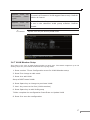
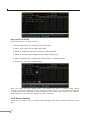
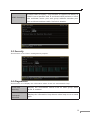
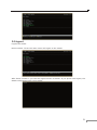
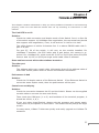
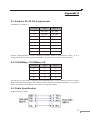
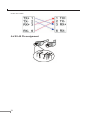
1
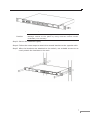
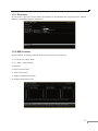
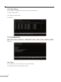
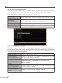
Trademarks Copyright © PLANET Technology Corp. 2004. Contents subject to revision without prior notice. PLANET is a registered trademark of PLANET Technology Corp. All other trademarks belong to their respective owners. Disclaimer PLANET Technology does not warrant that the hardware will work properly in all environments and applications, and makes no warranty and representation, either implied or ex-pressed, with respect to the quality, performance, merchantability, or fitness for a particular purpose. PLANET has made every effort to ensure that this User’s Manual is accurate; PLANET disclaims liability for any in-accuracies or omissions that may have occurred. Information in this User’s Manual is subject to change without notice and does not represent a commitment on the part of PLANET. PLANET assumes no responsibility for any inac-curacies that may be contained in this User’s Manual. PLANET makes no commitment to update or keep current the information in this User’s Manual, and reserves the right to make improvements to this User’s Manual and/or to the products described in this User’s Manual, at any time without notice. If you find information in this manual that is incorrect, mis-leading, or incomplete, we would appreciate your comments and suggestions. FCC Warning This equipment has been tested and found to comply with the limits for a Class A digital device, pursuant to Part 15 of the FCC Rules. These limits are designed to provide reasonable protection against harmful interference when the equipment is operated in a commercial environment. This equipment generates, uses, and can radiate radio frequency energy and, if not installed and used in accordance with the Instruc-tion manual, may cause harmful interference to radio communications. Operation of this equipment in a residential area is likely to cause harmful interference in which case the user will be required to correct the interference at his own expense. CE Mark Warning This is a Class A product. In a domestic environment, this product may cause radio interference, in which case the user may be required to take adequate measures. Revision PLANET 24 ports 10/100Mbps + 2 Gigabit-slot Ethernet Smart Switch User’s Manual FOR MODELS: FGSW-2402RS Part No.: 2010-000028-000 Table of Contents Chapter 1 TINTRODUCTION 1 1.1 Package Contents 1 1.2 About this Switch 1 1.3 Product Features 2 1.4 Product Specifications 2 Chaper 2 HARDWARE INSTALLATION 5 2.1 Font Panel 5 2.2 Rear Panel 6 2.3 Hardware installation 6 Chapter 3 CONFIGURATION 3.1 Connect to PC’s RS-232 serial port 9 9 3.2 Main Menu 10 3.3 Status 10 3.4 Configuration 12 3.5 Security 19 3.6 Diagnostics 19 3.7 Password 20 3.8 Reboot switch 20 3.9 logout 21 Chapter 4 TROUBLESHOOTING 23 APPENDIX A 25 A.1 Switch‘s RJ-45 Pin Assignments 25 A.2 10/100Mbps, 10/100Base-TX 25 A.3 Cable Specification 25 A.4 RJ-45 Pin assignment 26 Chapter 1 TINTRODUCTION 1.1 Package Contents Check the contents of your package for following parts: • FGSW-2402RS Gigabit Ethernet Smart Switch • Power Cord • RS-232 cable • User’s Manual • Rock-mounting blackest NOTE: if any of these pieces are missing or damage please con-tact your dialer immediately. 1.2 About this Switch FGSW-2402RS is a latest 10/100Mbps + 2 GbE-slot smart switch from PLANET. This switch provides 24 10/100Mbps ports and 2 Gigabit expansion slots for optional modules. FGSW-2402RS is a high performance switch that provides users with high-speed network connections with a store-and-forward architecture that is able to eliminate faulty packets. The FGSW-2402RS is equipped with a console interface and is able to manage basic switch functions such as bandwidth control, port status configuration, QOS, port trunking and VLAN parameters. The FGSW-2402RS supports auto learning and storage up to 8K of MAC addresses, as well as a non-blocking 8.8Gbps back plane for packet transmission. Also this switch supports two different types of VLAN, which are port-based VLAN and 802.1Q VLAN. The switch is suitable for the following application: Workgroup switch FGSW-2402RS has 24 10/100mbps ports and 2-slot available for a 10/100Mbps Ethernet ports optional 1000SX/1000LX/1000GT module. This switch provides a high performance solution for a variety of user applications Department Switch With its 8.8 Gigabits per second, non-blocking switch fabric, the FGSW-2402RS can easily provide a local, high bandwidth network for your departmental backbone. Choice for Gigabit optic module also can be deployed to extend the network distance 1 1.3 Product Features • 24 (10/100Mbps), 2-slot (10/100/1000Mbps) Gigabit Smart Switch • Provide 8.8Gbps switch fabric, non-blocking switch architec-ture • 8K MAC address, auto-aging • 2.5Mbit as packet buffer • Store-and-forward architecture, broadcast control • 24 TP ports 10/100Mbps Auto-Negotiation • 2 expansion slots, work with MII-SX/LX, GT and FX modules • Smart function support, Port Trunk, Port status configure, VLAN • 19-inch rack mount size • Comply with IEEE802.3, IEEE802.3u 10/100Base-TX, IEEE802.3ab, IEEE802.3z 1000Base-T, 1000Base-SX/LX Standard • Console interface for switch basic management and setup • Auto-MDI/MDI-X detection on each RJ-45 port 1.4 Product Specifications Model FGSW-2402RS 24-port 10/100Mbps + 2 Gigabit-slot Ethernet Smart Switch Hardware Specification 24 10/100Base-TX RJ-45 Auto-MDI ports Ports 2 open slots 1 RS-232 Operating Temp: 5 ~ 50°C (32 ~ 122°F) Environment Storage Temp: -40 ~ 70°C (-22 ~ 158°F) Humidity 0 ~ 90% non-condensing Dimensions 440 x 200 x 44 mm (W x D x H); 1U height Power supply 100 ~ 240V AC (± 10%), 50/60Hz (± 3%) auto-sensing Power Consumption 30 watts / 100BTU maximum Switch Specification Switch architecture Switch Fabric 2 Store-and-forward 8.8Gbps MAC Address table Memory Auto-MDI/ MDI-X 8K entries, auto learning/ageing 2.5Mbits for packet buffer Support on all RJ-45 ports Flow Control Back pressure for half duplex, IEEE 802.3x for full duplex Rate Control Per port TX/RX at 128K, 256K, 512K, 1M, 2M, 4M, 8M Port Trunk 8 Trunk with up to 4port per trunk Standard / Emission IEEE802.3 10BASE-T IEEE802.3u 100BASE-TX/100BASE-FX Network IEEE802.3z, ab Gigabit Ethernet 1000Base-SX/LX, 1000Base-T Standards IEEE802.3x Flow Control IEEE802.1p Class of service IEEE802.1Q VLAN Tagging Emission FCC, CE Class A 3 4 Chapter 2 HARDWARE INSTALLATION This section is describes the hardware features and installation of the 24-port 10/100Mbps + 2 Gigabit-slot Ethernet Smart Switch. – FGSW-2602RS FGSW-2402RS has provide two different module slots for expansion: • MII-SX - 1000Base-SX Gigabit Ethernet Module (SC, MM) • MII-LX - 1000Base-LX Gigabit Ethernet Module (SC, SM/MM) • MII-GT - 10/100/1000Mbps Ethernet Module (RJ-45 copper) • MII-ST – 100Base-FX Fast Ethernet Module (ST, MM) • MII-SC - 100Base-FX Fast Ethernet Module (SC, MM) 2.1 Font Panel The font panel of the FGSW-2402RS Ethernet Smart Switch consist RS-232 console port, LED indicators, 24 10/100BaseTX RJ45 ports and two expansion slot. For the open slot, please refer to the MII module’s installation guide for the hardware installation. The front panel of the switch is as blow. Figure 2-1 The Font Panel of FGSW-2402RS LED Indication of the Switch LED Power Statu Descript Green Power On Off Power is not connected This indicator light green when the port is connected to LNK/ACT Green an Ethernet or Fast Ethernet station, if the indicator is blinking green, it will be transmitting or receiving data on the network. This LED indicator light orange when a Fast Ethernet 100 Orange station is connected. It remains OFF, if an Ethernet station is connected. 5 2.2 Rear Panel The Rear Panel of the Switch is indicates an AC 3 pronged power socket and I/O power switch. This switch will work with AC in the range 100-240V AC, 50-60Hz Figure 2-2 Rear Panel of FGSW-2402RS Power Receptacle For the compatibility with electric service in most of areas, FGSW-2402RS’s power supply can automatically adjust line power in the range 100-240V AC, 50-60Hz. NOTE: The Switch is a power-required device, it means, the Switch will not work until it is powered. If your networked PCs will need to transmit data all the time, please consider vuse an UPS (Uninterrupted Power Supply) for your Switch. It will prevent you from network data loss. In some area, installing a surge suppression device may also help to protect your Switch from being damaged by unregulated surge or current to the Switch or the power adapter 2.3 Hardware installation FGSW-2402RS Ethernet Smart Switch can be placed on desktop or mounted on rock. If this Switch is used as standalone standard, the user can immediately use most of the features simply by attaching the cables and turning the power on Desktop installation To install an FGSW-2402RS on a desktop or shelf, simply complete the following steps: Step1: Attach the rubber feet to the recessed areas on the bottom of the switch. Step2: Place the FGSW-2402RS on a desktop or shelf near an AC power source. Step3: Keep enough ventilation space between the switch and the surrounding objects NOTE: Do not obstruct any vents at the sides of the case and keep water off. Rock-mount installation To install the switch in a 19-inch standard rack, follow the instructions described below. Step1: Place your FGSW-2402RS on a hard flat surface, with the front panel positioned towards your front side. Step2: Attach a rack-mount bracket to each side of the switch with supplied screws attached to the package. Figure 2-3 shows how to attach brackets to one side of the switch. 6 Figure 2-3 Attaching the brackets to the FGSW-2402RS Caution: You must use the screws supplied with the mounting brackets. Damage caused to the parts by using incorrect screws would invalidate your warranty. Step3: Secure the brackets tightly. Step4: Follow the same steps to attach the second bracket to the opposite side. Step5: After the brackets are attached to the switch, use suitable screws to securely attach the brackets to the rack 7 8 Chapter 3 CONFIGURATION The FGSW-2402RS is a Smart Ethernet Switch that can be controlled by the RS-232 console interface. This chapter describer how to configure the Switch through the RS-232 smart interface. 3.1 Connect to PC’s RS-232 serial port When you are ready to configure the smart functions of the Switch, make sure you had connected the supplied RS-232 serial cable to the RS-232 port at the front panel of your FGSW-2402RS Switch and your PC. Hyper Terminal In Windows 98/2000/XP, launch “HyperTerminal”, create a new connection, and adjust settings as below: • Baud per second: 19200 • Data bits: 8 • Parity: None • Stop bits: 1 • Flow Control: None 9 3.2 Main Menu Login is required to access the command console after the self-test completes successfully. The factory default Username is “admin” without password Control key describe: I / M / J / L: Up / down / left / right 1 / 2: Page up / Page down S: Save the configuration F: Refresh Space: Toggle selected item to change the value. 0: Exit current action After type in username and press enter twice then you can see the screen as below: To enter any of sub-menus, simply type the number on the main menu. 3.3 Status In this menu it shows the basic information of the Switch including, Switch overview, MIB counter and port status. 10 3.3.1 Overview In this menu, there are some basic information of the Switch like, System name, Switch MAC ID, Chip Mode ID and Vender ID 3.3.2 MIB Counter In this option, it shows transmit and receive counter of each port. 1 / 2: Page up / Page down P / X: Start / Stop Polling F: Refresh 0: Exit current action C: clear all counter T: Toggle Drop/CRC/Collision B: Toggle Byte/Packet unit 11 3.3.3 Port Status In this option, it displays the real-time status of each port. 0: Exit current action 1/2: Page up/ Page down F: Refresh 3.4 Configuration There are 8 main functions in Configuration menu, which is Port, Trunking, Global, QOS, Priority Tag Insert/Remove, VLAN Global control, VLAN member Setup and Device features. 3.4.1 Port In this function, user can set up every port’s status Use I/M/J/L key to move between items 12 Enabled The port can be set enable or disable mode. If the port status is in disable then this port will not receive or transmit any packet. Default: enable. Speed Set the port link speed and duplex mode base on auto-nego- advertisement tiation. Default 100M Full. Flow Control Enable or disable flow control. Default: Enable Rx Bandwidth Per port packet transmission control (128K, 256K, 512K, 1M, 2M, 4M, 8M). Default: non-control. Tx Bandwidth Per port packet transmission control (128K, 256K, 512K, 1M, 2M, 4M, 8M). Default: non-control. After the port setting, please press “S” to save the configuration. Then press “R” to restart the Auto-Negotiation to make the setting activated right away. Be noted, the Switch support auto-negotiation, for a device do not support auto-negotiation, please remain in 100M Full, the Switch will auto-detect the optimal speed, i.e. 100Mbps Half-duplex or 10Mbps Half-duplex. 3.4.2 Trunking In this function, user is able to enable or disable Trunking at each group. (8 trunks group base on ports) 13 Be noted, the Switch at the other end should also turn on the port-based trunk with the same port number to get the optimal usage of the trunk-bandwidth. 3.4.3 Global In this function, user is able to enable/disable the global setting of the Switch’s ports. Options includes, Half-duplex back Pressure flow, Broadcast Storm Filtering Control and Loop Detect Enable or disable half duplex backpressure flow. To disHalf duplex back pressure flow able will turn off the half-duplex back pressure control and drop the packets without sending out any collision from the switch port. Default: Enable Enable or disable broadcast storm filtering. Enable will turn Broadcast storm on the capability to drop broadcast packets after a continu- filtering control ous 64 broadcast packets. Default: Disable. Enable or disable loop detect function. To turn on will loop Loop Detect detect the connection status. This feature is used for diagnose purpose. Default: Disable. 14 3.4.4 QOS In this function, user is able to enable TOS/Diff Serv Priority, 802.1p priority; adapted flow control, Priority weight ration (high: low) and Force set high-priority port. TOS/Diff Serv priority Enable or disable TOS priority. Check the packets’ IP TOS priority tag and base on the priority to forward the packets. Default: Disable Enable or disable 802.1p priority. Check the packet’s 802.1p 802.1p priority priority and base on the priority to forward the packets. Default: Disable. Adapted flow control Enable or disable priority of flow control. Check the priority and turn off the flow-control when high priority packets received. Default: Disable. Priority weight Use M key to move down to Priority weight ration then use ration (high: Space key to select the ration priority. Available weights, 1: low) 0; 4:1, 8:1, 16:1. Default: 16:1. Force set highpriority port Use M key to move down the cursor and select the ports, by Space toggle, that you would like to set base on the QoS options above. Be noted, the switch support dual priority per port, the QoS setting will base on the menu above to arrange each port’s high/low priority. 15 3.4.5 Priority tag Insert/Remove In this menu, user is able to insert or remove Priority tag each port. The option includes: Insert Tag (high priority only), Insert Tag (all frame), Remove Tag and Don’t Touch. Please also refer to VLAN section 3.4.6 and 3.4.7 for more. Insert Tag (high priority only): Insert Tag (all frame): Insert priority tag into the untagged high-priority frame Insert priority tag into the all untagged frame Remove Tag: Remove the VLAN tag from all tagged frame Don’t touch: The default setting, which means no modify 3.4.6 VLAN Global Control This menu is allow user to enable VLAN’s global capabilities including, VLAN function, Unicast packet Inter-VLAN Leaky, ARP broadcast packet Inter-VLAN Leaky, IP Multicast packet Inter-VLAN Leaky, 802.1Q VLAN tag aware, Ingress Rule for Acceptable frame type and Ingress Rule for Ingress Filtering. VLAN function Enable VLAN, Default disable Unicast packet Enable the packet to be forward to a destination port at Inter-VLAN Leaky different VLAN. Default: disable ARP broadcast packet Inter-VLAN Leaky Enable ARP frame to broadcast to all switch port Default: disable IP Multicast packet Enable multicast to be flood to all the multicast group Inter-VLAN Leaky member. Default: disable 802.1Q VLAN tag aware 16 Enable 802.1Q VLAN tag. Default: disable Ingress Rule Acceptable for frame types Ingress Rule Ingress filtering Notice: for To permit all frames or VLAN-tagged frames only. Default: Admin all frames Enable filter the frame received from a port which port is not in the classified VLAN group member. Default: disable Ingress rule only for 802.1Q VLAN mode 3.4.7 VLAN Member Setup This menu is for user to add VLAN member to each port. The Switch supports up to 32 VLAN groups for port-based VLAN and 802.1q tag VLAN. 1. Press number 7 from Configuration menu for VLAN Member setup 2. Press E to change to edit mode 3. Press A to add VLAN Setup a PORT based VLAN: 4. Press Space key to change to port-base VLAN 5. Use L key move to the Port (VLAN member) 6. Press Space key to add VLAN group 7 After complete the configuration Press Enter to Update VLAN 8. Press S to save the configuration 17 Setup a 802.1Q VLAN: Follow from Step 1 to Step 3 above 4. Press Space key to change to 802.1Q mode 5. Use L key move to the right hand side 6. Move to VLAN ID then Press Enter to add VLAN ID 7. Move to the Port Press Space key to add VLAN group 8. After complete the configuration Press Enter to Update VLAN 9. Press S to save the configuration After the setup of port’s VLAN above, the Switch will base on global VLAN setting (section 3.4.6) and VLAN tag priority insertion (section 3.4.5) and the VLAN setting here to filter/forward the packets to each switching port. Please also consult your network administrator for the detailed VLAN plan of the network. 3.4.8 Device Feature This function is allow user to enable IGMP Snooping and display the IP multicast router port 18 Enable IGMP Snooping. This function is support the ability of IGMP Snooping IGMP Control packets and IP multicast data packets to learn the multicast router port and group address member port into multicast address table. Default is disable. 3.5 Security This function is for Future management purpose. 3.6 Diagnostics This function is to display the information about Trunk link and Network loop Trunk link Display the information about trunk at each group when warning trunk is enabled. Network loop fault port detected Display the information loop detect when loop occur on each port. 19 3.7 Password This function is allow user to modify username and password. The factory default Username is “admin” without password Press number 5 from the main menu to select password Press 1 to modify the username Press 2 to modify the password 3.8 Reboot switch In this function, it provides two different reboot functions which is to reset the switch to Default and restart switch Press number 6 from main menu to select reboots Press D to reset the switch to default setting and reboot. Press R to restart switch right away. 20 3.9 logout Logout the switch Press number 7 from the main menu will logout to the switch. After Press number 7 you can see logout screen as below. If you press enter again, the Switch will prompt login screen again. 21 22 Chapter 4 TROUBLESHOOTING This chapter contains information to help you solve problems. If Switch is not functioning properly, make sure the Ethernet Switch was set up according to instructions in this manual. The Link LED is not lit Solution: Check the cable connection and duplex mode of the Switch. Port 1 to Port 24 of the switch support 10/100Mbps auto-negotiation, the connected end should also support auto-negotiation, if not, it will work at 10 Half or 100 Half. The cable distance is within 100meters Cat. 3 or above EIA568 cable with 2pair or 4-pair. For port 25, 26 of the switch, it will vary on the module installed. For 1000Base-T interface, Cat.5/5e cable with 4-pair below 100 meters is required. For 1000Base-SX, multi-mode 62.5/125 or 50/125μm below 220/550 meters. And 10/125 or 9/125μm single mode cable 10km is allowed. Some stations cannot talk to other stations located on The other port Solution: The address table may contain older information than of the address table of that node. Please power down to refresh the address information. Performance is bad Solution: Check the full duplex status of the Ethernet Switch. If the Ethernet Switch is not at the same duplex mode, then the performance will be poor. Console can not display Solution: Check the connection between the PC and the Switch. Please use the supplied console cable to connect the two ends firmly. Then check the COM port (1 or 2) and baudrate of the terminal program, it should be 19200, n, 8, 1. If you are using HyperTeminal, please exit the program and restart again. Then power off, and power on the Switch. The Switch should prompt the login screen. In many cases, 10Base-T LANs can quickly and easily upgrade to 100Base-TX networks. 23 24 Appendix A A.1 Switch‘s RJ-45 Pin Assignments 1000Mbps, 1000Base T Contact MDI MDI-X 1 BI_DA+ BI_DB+ 2 BI_DA- BI_DB- 3 BI_DB+ BI_DA+ 4 BI_DC+ BI_DD+ 5 BI_DC- BI_DD- 6 BI_DB- BI_DA- 7 BI_DD+ BI_DC+ 8 BI_DD- BI_DC- Implicit implementation of the crossover function within a twisted-pair cable, or at a wiring panel, while not expressly forbidden, is beyond the scope of this standard. A.2 10/100Mbps, 10/100Base-TX Contact MDI MDI-X 1 1 3 2 2 6 3 3 1 6 6 2 The TP ports of the Switch supports Auto-MDI detection, if the connected device is MDIdevice like Ethernet Adapter, the Switch all auto adjust the contact to MDI-X. In contrast, if the connected end is MDI-X, the Switch will adjust to MDI. A.3 Cable Specification Straight through cable 25 Cross over cable A.4 RJ-45 Pin assignment 26