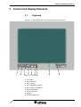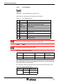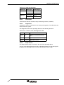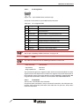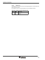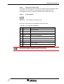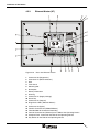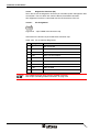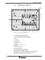
1
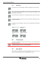
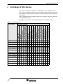
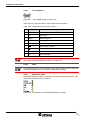
User Manual
TesiP@n TP121
Part Number:
80860.576
Version:
3
Date:
15.10.2004
Valid for:
TP121x/0xxxx032
Version
1
2
3
Date
27.08.2002
22.01.2004
15.10.2004
Modifications
First Edition
Ordering data added, text revisions.
Restriction of validity range.
This manual, including all illustrations contained herein, is copyright protected. Use of this manual by any third
party in departure from the copyright provision is forbidden. No part of this manual may be reproduced, translated or electronically or photographically archived or altered without the express written consent from Sütron
electronic GmbH. Violations shall be cause for damage liability.
Sütron electronic reserves the right to make any changes that contribute to technical improvement.
Overall Table of Contents
1
Important Notes ....................................................................................................... 1-1
1.1
2
1.1.1
General Symbols ................................................................................. 1-1
1.1.2
Specific Symbols ................................................................................. 1-1
1.2
Safety Notes ............................................................................................. 1-2
1.3
Intended Use............................................................................................. 1-2
1.4
Target Group............................................................................................. 1-2
Installation and Commissioning ............................................................................... 2-1
2.1
Unpacking the Device ............................................................................... 2-1
2.2
Mounting the Device ................................................................................. 2-1
2.2.1
Front Panel Dimensions ...................................................................... 2-2
2.2.2
Mounting Cutout .................................................................................. 2-3
2.2.3
Side View, Mounting Depth ................................................................. 2-4
2.2.3.1
Standard Device .........................................................................................................2-4
2.2.3.2
Field Bus Device.........................................................................................................2-5
2.3
2.3.1
3
Connecting the device .............................................................................. 2-6
Supply Voltage 24 V ............................................................................ 2-6
2.4
Switching the Device on............................................................................ 2-8
2.5
Identification.............................................................................................. 2-8
Control and Display Elements ................................................................................. 3-1
3.1
3.1.1
4
Symbols .................................................................................................... 1-1
Keyboard................................................................................................... 3-1
Help Keys ............................................................................................ 3-2
3.2
Touch screen ............................................................................................ 3-2
3.3
Key „Reset“ ............................................................................................... 3-2
3.4
Display ...................................................................................................... 3-3
3.5
Key Switch (Option) .................................................................................. 3-3
Interfaces of the Device ........................................................................................... 4-1
4.1
4.1.1
4.2
4.2.1
4.3
Digital Outputs (X2)................................................................................... 4-2
Pin Assignment .................................................................................... 4-2
Digital Inputs (X3) ..................................................................................... 4-3
Pin Assignment .................................................................................... 4-3
Standard Interfaces (X4, X5) .................................................................... 4-4
4.3.1
RS232c (X4-COM1)............................................................................. 4-5
4.3.1.1
Pin Assignment...........................................................................................................4-5
4.3.2
TTY / 20 mA current loop (X4-COM2) ................................................. 4-6
4.3.2.1
Pin Assignment...........................................................................................................4-6
4.3.2.2
Termination.................................................................................................................4-6
i
Overall Table of Contents
4.3.3
RS485 (X4-COM2)............................................................................... 4-7
4.3.3.1
Pin Assignment........................................................................................................... 4-7
4.3.3.2
Termination................................................................................................................. 4-8
4.3.4
RS232c (X4-COM2) ............................................................................. 4-9
4.3.4.1
Pin Assignment........................................................................................................... 4-9
4.3.4.2
Termination................................................................................................................. 4-9
4.3.5
Ethernet (X5)...................................................................................... 4-10
4.3.5.1
Pin Assignment......................................................................................................... 4-10
4.3.5.2
Cable ........................................................................................................................ 4-10
4.3.5.3
Diagnostics ............................................................................................................... 4-11
4.4
4.4.1
CANopen Slave (X6).......................................................................... 4-12
4.4.1.1
Pin Assignment......................................................................................................... 4-13
4.4.1.2
Cable ........................................................................................................................ 4-13
4.4.1.3
Termination............................................................................................................... 4-14
4.4.1.4
Diagnostics ............................................................................................................... 4-14
4.4.1.5
Slope Control............................................................................................................ 4-14
4.4.2
DeviceNet Slave (X6)......................................................................... 4-15
4.4.2.1
Pin Assignment......................................................................................................... 4-16
4.4.2.2
Cable ........................................................................................................................ 4-16
4.4.2.3
Termination............................................................................................................... 4-17
4.4.2.4
Diagnostics ............................................................................................................... 4-17
4.4.2.5
Slope Control............................................................................................................ 4-17
4.4.3
MPI Slave (X6) ................................................................................... 4-18
4.4.3.1
Pin Assignment......................................................................................................... 4-19
4.4.3.2
Cable ........................................................................................................................ 4-19
4.4.3.3
Termination............................................................................................................... 4-19
4.4.3.4
Diagnostics ............................................................................................................... 4-20
4.4.4
PROFIBUS-DP Slave (X6)................................................................. 4-21
4.4.4.1
Pin Assignment......................................................................................................... 4-22
4.4.4.2
Cable ........................................................................................................................ 4-22
4.4.4.3
Termination............................................................................................................... 4-23
4.4.4.4
Diagnostics ............................................................................................................... 4-23
4.5
4.5.1
Field Bus Master Interfaces .................................................................... 4-24
CANopen master (X7)........................................................................ 4-24
4.5.1.1
Pin Assignment......................................................................................................... 4-25
4.5.1.2
Cable ........................................................................................................................ 4-25
4.5.1.3
Termination............................................................................................................... 4-26
4.5.1.4
Diagnostics LEDs ..................................................................................................... 4-26
4.5.1.5
Diagnostics Interface (X6) ........................................................................................ 4-26
4.5.1.5.1
4.5.2
Pin Assignment .................................................................................................. 4-26
DeviceNet Master (X7)....................................................................... 4-28
4.5.2.1
Pin Assignment......................................................................................................... 4-29
4.5.2.2
Cable ........................................................................................................................ 4-29
4.5.2.3
Termination............................................................................................................... 4-30
4.5.2.4
Diagnostics LEDs ..................................................................................................... 4-30
4.5.2.5
Diagnostics Interface (X6) ........................................................................................ 4-31
4.5.2.5.1
4.5.3
ii
Field Bus Slave Interfaces ...................................................................... 4-12
Pin Assignment .................................................................................................. 4-31
Ethernet Master (X7).......................................................................... 4-32
4.5.3.1
Pin Assignment......................................................................................................... 4-33
4.5.3.2
Cable ........................................................................................................................ 4-33
4.5.3.3
Diagnostics LEDs ..................................................................................................... 4-33
Overall Table of Contents
4.5.3.4
4.5.3.4.1
Pin Assignment ..................................................................................................4-34
4.5.4
INTERBUS Master (REMOTE) .......................................................... 4-35
4.5.4.1
Pin Assignment.........................................................................................................4-36
4.5.4.2
Cable ........................................................................................................................4-36
4.5.4.3
Diagnostics LEDs .....................................................................................................4-36
4.5.4.4
INTERBUS programming interface (PRG) ...............................................................4-37
4.5.4.4.1
Pin Assignment ..................................................................................................4-38
4.5.5
PROFIBUS-DP Master (X7) .............................................................. 4-39
4.5.5.1
Pin Assignment.........................................................................................................4-40
4.5.5.2
Cable ........................................................................................................................4-40
4.5.5.3
Termination...............................................................................................................4-41
4.5.5.4
Diagnostics LEDs .....................................................................................................4-41
4.5.5.5
Diagnostics Interface (X6) ........................................................................................4-41
4.5.5.5.1
4.6
Pin Assignment ..................................................................................................4-41
Memory Card .......................................................................................... 4-43
4.6.1
Inserting the Memory Card ................................................................ 4-43
4.6.2
Ejecting the Memory Card ................................................................. 4-43
4.7
5
Diagnostics Interface (X6) ........................................................................................4-34
Shielding D-SUB Connectors.................................................................. 4-44
Maintenance and Servicing ..................................................................................... 5-1
5.1
Front Panel ............................................................................................... 5-1
5.2
Fuse .......................................................................................................... 5-1
5.3
Battery (option) ......................................................................................... 5-1
5.3.1
Changing the Battery ........................................................................... 5-2
5.3.2
Battery Disposal................................................................................... 5-3
6
Technical Data......................................................................................................... 6-1
7
Ordering Data .......................................................................................................... 7-1
A
Index ........................................................................................................................A-1
iii
Overall Table of Contents
iv
Important Notes
1
Important Notes
1.1
Symbols
The symbols in this manual are used to draw your attention on notes and dangers.
1.1.1
General Symbols
Danger
This symbol is used to refer to instructions which, if ignored or not carefully followed
could result in personal injury.
Note
This symbol indicates application tips or supplementary notes.
Reference to source of information
This symbol refers to detailed sources of information on the current topic.
1.1.2
Specific Symbols
The following symbols indicate specific dangers which could result in damage to
equipment or personal injury or even up to the death of the operator.
Danger - Electric Shock
Danger - Corrosive
Danger - Toxic
Danger - Explosive
Danger - Fire
Danger - Infrared Light
Danger - Electrostatic Charge
1-1
Important Notes
1.2
Safety Notes
–
Read this manual carefully before using the operating device. Keep this manual
in a place where it is always accessible to all users.
–
Proper transportation, handling and storage, placement and installation of this
product are prerequisites for its subsequent flawless and safe operation.
–
This user manual contains the most important information for the safe operation
of the device.
–
The user manual, in particular the safety notes, must be observed by all personnel working with the device.
–
Observe the accident prevention rules and regulations that apply to the operating
site.
–
Installation and operation must only be carried out by qualified and trained personnel.
1.3
Intended Use
–
The device is designed for use in the industry.
–
The device is state-of-the art and has been built to the latest standard safety requirements. However, dangerous situations or damage to the machine itself or
other property can arise from the use of this device.
–
The device fulfills the requirements of the EMC directives and harmonized European standards. Any modifications to the system can influence the EMC behavior.
This is a class A device. This device may cause radio interference in residential areas. In this case, the user may be required to introduce appropriate countermeasures, and to bear the cost of same.
1.4
Target Group
All configuration, programming, installation, commissioning, operating and maintenance work in connection with the automation system must be performed by trained
personnel only (e.g. qualified electricians, electrical engineers, etc.).
The configuration and programming personnel must be familiar with the safety concepts of automation technology.
The operating personnel must have been trained in handling the controller and be
familiar with the operating instructions.
The installation, commissioning and maintenance personnel must have an education
which entitles them to work on automation systems.
1-2
Installation and Commissioning
2
Installation and Commissioning
2.1
Unpacking the Device
Unpack all parts carefully and check the contents for any visible damage in transit.
Also check whether the shipment matches the specifications on your delivery note.
If you notice damages in transit or discrepancies, please contact our sales department immediately.
2.2
Mounting the Device
When installing the operating device, keep a minimum clearance of 30 mm (1.181")
around the operating device to ensure adequate air circulation.
When the operating device is installed horizontally, please note that additional sources of heat beneath the operating device may result in heat accumulation.
Make sure to allow sufficient heat dissipation!
Comply with the allowable temperature range listed in the technical data for the use
of the operating device!
To maintain the specified degree of protection, make sure the seal is evenly seated
on the installation surface and the hexagon nuts are tightened uniformly.
Ensure that the maximum torque of 1.2 Nm is not exceeded.
The operating device can be easily and quickly mounted from the rear of the operating device. This is particularly recommended for mounting in switchboards with a
plate thickness of approx. 1 mm to 8 mm (0.039" to 0.315").
1. Insert the operating device from the front through the mounting cutout.
2. Fasten the operating device using hexagon nuts.
2-1
Installation and Commissioning
2-2
2.2.1
Front Panel Dimensions
Figure 2-1
Front panel dimensions
Installation and Commissioning
2.2.2
Mounting Cutout
Figure 2-2
Mounting cutout
A Mounting Cutout
B Front Panel
2-3
Installation and Commissioning
2-4
2.2.3
Side View, Mounting Depth
2.2.3.1
Standard Device
Figure 2-3
Side view and mounting depth for the standard device
1
Front Panel
2
Circumferential Seal
3
Press-in Threaded Bolt M4 x 18 mm (0.709")
4
Mounting Surface Thickness 1 mm to 8 mm (0.039" to 0.315")
5
Spring Lock Washer B4 DIN 127 Form B (not supplied)
6
Nut M4 DIN 934 (not supplied)
Installation and Commissioning
2.2.3.2
Field Bus Device
Figure 2-4
Side view and mounting depth for the field bus device
1
Front Panel
2
Circumferential Seal
3
Press-in Threaded Bolt M4 x 18 mm (0.709")
4
Mounting Surface Thickness 1 mm to 8 mm (0.039" to 0.315")
5
Spring Lock Washer B4 DIN 127 Form B (not supplied)
6
Nut M4 DIN 934 (not supplied)
2-5
Installation and Commissioning
2.3
Connecting the device
2.3.1
Supply Voltage 24 V
The supply voltage is connected via the connector X1.
The unit is equipped with a reverse voltage protection. If the polarity is not correct,
the unit does not operate.
This unit conforms to the safety class I. For safe operation it is necessary to use
safety extra-low voltage (SELV) in accordance with DIN EN 61131 for the supply voltage.
Connector in the operating device: 3-pin connector Phoenix Contact COMBICON
MSTBV 2,5/3-GF.
Table 2-1
Pin
Pin assignment supply voltage
Designation
1
Function
Low-noise earth
2
0V
Supply voltage 0 V
3
24 VDC
Supply voltage 24 VDC
The suitable female connector Phoenix Contact COMBICON MSTB 2,5/3-STF is
supplied.
Cables with finely stranded conductors with a minimum cross-section of 0.75 mm²
(18 AWG) and a maximum cross-section of 2.5 mm² (14 AWG) must be used for the
supply voltage.
Hazardous voltages can exist inside electrical installations that can pose a danger to
humans. Coming in contact with live parts may result in electric shock!
Use the following procedure to connect the operating device to the supply voltage:
1. Strip approx. 30 mm (1.181") off the outer cable sheath and approx. 5 mm
(0.197") off the wires.
Figure 2-5
2-6
Preparing the cable
Installation and Commissioning
2. Fit the wires with wire end ferrules and connect the wires to the connector.
Figure 2-6
Connecting the female connector strip
If shielded connecting cables are used in the supply voltage area, the shield should
be connected to pin 1.
3. Plug the female connector strip onto connector X1.
Figure 2-7
Female connector strip is plugged on
4. Secure the female connector strip in place with a screw-type locking to prevent
it from slipping out.
A separate conductor must always be provided for the protective grounding at the
threaded bolt. The conductor must have a minimum cross-section of 1.5 mm²
(16 AWG) and must be kept as short as possible. Complying with this will increase
operating safety
2-7
Installation and Commissioning
2.4
Switching the Device on
After you applied the supply voltage, the operating device starts the boot loader from
the internal flash memory. The status LEDs flash in short distances. The further behavior depends on the device variant (web panel, graphics panel, control panel or
open platform).
2.5
Identification
You can identify the operating device by the nameplate on the rear.
Figure 2-8
2-8
Nameplate (Example)
1
Order Number
2
BootLoader Version (Version on Delivery)
3
MAC Address
4
Voltage and Current
5
Serial Number
Control and Display Elements
3
Control and Display Elements
3.1
Keyboard
The keys are positioned under an environmental-proof polyester foil.
Figure 3-1
Front view
1
Key „ABC“
2
Key „New Task“
3
Key „Hot Key“
4
Key „Right Mouse Button“
5
Key „Contrast / Brightness“
6
Status LED Mode
7
Status LED Info
8
Display
9
Device Designation
3-1
Control and Display Elements
3.1.1
Help Keys
Use this key to show a soft keyboard. To hide the keyboard, press the key again.
Use this key to open the Task Manager in order to change to another task or use this
key to close the Task Manager. When you press this key again, the dialog for changing to another task is closed.
Use this key to open the Service tool. To exit the Service tool, press the key again.
Use this key to open the context menu, which can usually be reached by pressing
the right mouse button.
To define the contrast / brightness setting, use the key combinations shown below
as follows:
To increase the contrast:
To increase the
brightness:
To reduce the contrast:
To reduce the brightness:
3.2
Touch screen
The device is equipped with a resistive 4 wire touch screen. You operate the device
using this touch screen.
To protect the touch screen you can use special protection foils. You receive a corresponding protection foil directly from Sütron electronic.
3.3
Key „Reset“
The Reset key is located on the rear of the operating device. You can use this key to
perform a restart. During this process, the digital outputs are reset.
3-2
Control and Display Elements
3.4
Display
Danger - Toxic!
If the display is damaged, avoid touching, swallowing or breathing in the liquids or
gases which may leak out!
Danger - Corrosive!
If the display is damaged, avoid touching, swallowing or breathing in the liquids or
gases which may leak out!
The operating device is equipped with a TFT display.
3.5
Key Switch (Option)
A key switch is located on the side of the device. You can use the software of the
operating device to specify the function of the key switch.
For further information on this topic, see the device-specific software manual.
3-3
Control and Display Elements
3-4
Interfaces of the Device
4
Interfaces of the Device
The device can either be supplied as a standard device or as a field bus device.
The universal interface X4 combines several interface standards into one connector.
The connector is divided into two channels. Channel COM1 is operated separately
from COM2.
For the COM2 channel, the protocol-specific use only allows one of the three interface standards to be used.
Depending on the device variant, several interfaces are available to you:
Table 4-1
Device Variants
Inputs (X3)
RS232c (X4-COM1)
RS232c, RS485 (X4-COM2)
TTY / 20mA (X4-COM2)
Ethernet (X5)
Diagnostics (X6)
CANopen Slave (X6)
PROFIBUS-DP Slave (X6)
MPI Slave (X6)
DeviceNet Slave (X6)
INTERBUS Master (REMOTE)
CANopen Master (X7)
DeviceNet Master (X7)
Ethernet Master (X7)
PROFIBUS-DP Master (X7)
Available interfaces
Outputs (X2)
Order number
TPxxxx-xx/xx00xx
X
X
X
X
X
X
-
-
-
-
-
-
-
-
-
-
TPxxxx-xx/xx01xx
-
-
X
-
-
X
-
-
-
-
-
-
-
-
-
-
TPxxxx-xx/xx02xx
X
X
X
-
-
X
-
-
-
-
-
-
-
-
-
-
TPxxxx-xx/xx03xx
-
-
X
X
-
X
-
-
-
-
-
-
-
-
-
-
TPxxxx-xx/0012xx
X
X
X
-
-
X
-
X
-
-
-
-
-
-
-
-
TPxxxx-xx/0013xx
X
X
X
-
-
X
-
-
X
-
-
-
-
-
-
-
TPxxxx-xx/0017xx
X
X
X
-
-
X
-
-
-
X
-
-
-
-
-
-
TPxxxx-xx/0018xx
X
X
X
-
-
X
-
-
-
-
X
-
-
-
-
-
TPxxxx-xx/0050xx
X
X
X
-
-
X
-
-
-
-
-
X
-
-
-
-
TPxxxx-xx/0051xx
X
X
X
-
-
X
X
-
-
-
-
-
X
-
-
-
TPxxxx-xx/0053xx
X
X
X
-
-
X
X
-
-
-
-
-
-
X
-
-
TPxxxx-xx/0054xx
X
X
X
-
-
X
X
-
-
-
-
-
-
-
X
-
TPxxxx-xx/0055xx
X
X
X
-
-
X
X
-
-
-
-
-
-
-
-
X
4-1
Interfaces of the Device
4.1
Digital Outputs (X2)
All outputs are protected against polarity reversal. In case of wrong polarity, the relevant outputs are not operated.
The supply voltage for the outputs must be supplied at the plug-in connector. This
supply voltage will then also be available for the digital inputs.
The outputs are controlled from within the controller program.
4.1.1
Pin Assignment
Figure 4-1
6 pin MINI-COMBICON connector
Connector in the operating device: 6 pin plug-in connector Phoenix Contact MINICOMBICON connector MCV 1,5/6-G-3,5.
Table 4-2
4-2
Pin assignment of the digital outputs
Pin
Designation
Function
1
+24 V
Supply Voltage 24 V DC for Outputs A0.0 to
A0.3
2
0V
Reference Potential 0 V
3
A0.0
Output A0.0
4
A0.1
Output A0.1
5
A0.2
Output A0.2
6
A0.3
Output A0.3
Interfaces of the Device
4.2
Digital Inputs (X3)
All inputs are non-floating and are galvanically isolated by optocouplers.
The supply voltage is provided to the digital inputs at the connector once you applied
the supply voltage to the digital outputs. A fuse protection should be provided externally.
4.2.1
Pin Assignment
Figure 4-2
12 pin MINI-COMBICON connector
Connector in the operating device: 12 pin plug-in connector Phoenix Contact MINICOMBICON connector MCV 1,5/12-G-3,5.
Table 4-3
Pin assignment of the digital inputs
Pin
Designation
Function
1
+24 V
Supply voltage +24 V DC
2
E0.0
Input E0.0
3
-
Supply Voltage 0 V, for Transducer E0.0
4
+24 V
Supply Voltage +24 V DC
5
E0.1
Input E0.1
6
-
Supply Voltage 0 V, for Transducer E0.1
7
+24 V
Supply Voltage +24 V DC
8
E0.2
Input E0.2
9
-
Supply Voltage 0 V, for Transducer E0.2
10
+24 V
Supply Voltage +24 V DC
11
E0.3
Input E0.3
12
-
Supply Voltage 0 V, for Transducer E0.3
4-3
Interfaces of the Device
4.3
Standard Interfaces (X4, X5)
The figure shows an operating device equipped with a maximum of features. The
availability of some of the illustrated features vary with the device variant.
Figure 4-3
Rear view TTY / RS232c / RS485
1
Seal
2
Front Panel
3
Mounting Bolt
4
Nameplate
5
Battery Information
6
Warning
7
Connector X1 (Supply Voltage)
8
Assignment Connector X1
9
Reset Key
10 Connector X2 (Outputs)
11 Connector X3 (Inputs)
12 Female Connector X4 (RS485/RS232c)
13 Termination Switch (X4-COM2 RS485)
14 Threaded Bolt for Protective Grounding
15 Female Connector X5 (Ethernet) on the Side of the Operating Device
16 Compact Flash, Inserted on the Side of the Operating Device
17 Key Switch on the Side of the Operating Device
4-4
Interfaces of the Device
4.3.1
RS232c (X4-COM1)
As this interface is not galvanically isolated, it should only be used for debugging,
monitoring or a logging printer.
4.3.1.1
Pin Assignment
Figure 4-4
25 pin D-SUB female connector strip
Connector in the operating device: 25 pin D-SUB female connector strip.
Table 4-4
Pin
Pin assignment RS232c
Designation
1
Function
Low-Noise Ground
2
TD
Transmitted Data
3
RD
Received Data
4
RTS
Request to Send
5
CTS
Clear to Send
7
SGND
Signal Ground
20
DTR
Data Transfer Request
The D-SUB connector strips must be shielded sufficiently.
See chapter “Shielding D-SUB Connectors“ on page 4-44.
4-5
Interfaces of the Device
4.3.2
TTY / 20 mA current loop (X4-COM2)
Depending on the wiring, it is possible to connect the interface either as an active or
passive current loop. The transmit line and the receive line are each provided with a
separate 20 mA power source. The compliance voltage is approx. 24 VDC.
The 20 mA power should be supplied by the transmitter unit. This decreases
crosstalk on the signal lines considerably.
In idle state (signal logic 1), a 20 mA current loop can be measured in the cable.
Signal Logic 1
Current Flow 20 mA
Signal Logic 0
Current Flow Interrupted
4.3.2.1
Pin Assignment
Figure 4-5
25 pin D-SUB female connector strip
Connector in the terminal: 25 pin D-SUB female connector strip.
Table 4-5
Pin assignment TTY / 20 mA, passive
Pin
Designation
Function
10
T+
Transmitted Data, Positive Polarity
13
R+
Received Data, Positive Polarity
14
R-
Received Data, Negative Polarity
19
T-
Transmitted Data, Negative Polarity
Table 4-6
Pin assignment TTY / 20 mA, active
Pin
Designation
Function
10
T+
Transmitted Data, Positive Polarity
12
S1+
Power Source 1, Positive Polarity
13
R+
Received Data, Positive Polarity
14
R-
Received Data, Negative Polarity
16
S2+
Power Source 2, Positive Polarity
19
T-
Transmitted Data, Negative Polarity
21
S1-
Current Sink 1, Negative Polarity
24
S2-
Current Sink 2, Negative Polarity
The D-SUB connector strips must be shielded sufficiently.
See chapter “Shielding D-SUB Connectors“ on page 4-44.
4.3.2.2
Termination
When channel COM2 is operated as a current loop, the termination for the RS485
must be switched OFF.
4-6
Interfaces of the Device
4.3.3
RS485 (X4-COM2)
The interface is suitable for point-to-point and for multi-point connections.
The wires belonging together are marked with „A“ and „B“. Some descriptions refer
to the pins with „+“ and „-“ , where A = + and B = -.
Signal Logic 1
UA - UB <= -0.3 V i.e. (UA < UB)
Signal Logic 0
UA - UB >= +0.3 V i.e. (UA > UB)
4.3.3.1
Pin Assignment
Figure 4-6
25 pin D-SUB female connector strip
Connector in the operating device: 25 pin D-SUB female connector strip.
Table 4-7
Pin assignment RS485
Pin
Designation
Function
8
T(A)
Transmitted Data (-)
9
T(B)
Transmitted Data (+)
11
SGND
Signal Ground
22
R(A)
Received Data (-)
23
R(B)
Received Data (+)
The D-SUB connector strips must be shielded sufficiently.
See chapter “Shielding D-SUB Connectors“ on page 4-44.
4-7
Interfaces of the Device
4.3.3.2
Termination
For point-to-point connections, always activate the termination. For multi-point connections, only activate the termination at the cable end.
Figure 4-7
Table 4-8
Block diagram termination RS485
Resistance values termination RS485
Designation
Value
R1, R3
510 Ohm
R2
150 Ohm
R4
120 Ohm
The switch positions for ON or OFF are printed onto the termination switch. Only the
specified switch positions are allowed.
Table 4-9
S1
Termination switch
S2
Transmitter
S4
Function
Receiver
I
I
I
I
Termination is ON
–
–
–
–
Termination is OFF
Legend for table:
I = Switch ON
- = Switch OFF
4-8
S3
Interfaces of the Device
4.3.4
RS232c (X4-COM2)
The interface can be used for any type of application.
4.3.4.1
Pin Assignment
Figure 4-8
25 pin D-SUB female connector strip
Connector in the operating device: 25 pin D-SUB female connector strip.
Table 4-10
Pin assignment RS232c
Pin
Designation
Function
6
TD
Transmitted Data
15
CTS
Clear to Send
17
RTS
Request to Send
18
RD
Received Data
25
SGND
Signal Ground
The D-SUB connector strips must be shielded sufficiently.
See chapter “Shielding D-SUB Connectors“ on page 4-44.
4.3.4.2
Termination
When channel COM2 is operated as a RS232, the termination for the RS485 must
be switched OFF.
4-9
Interfaces of the Device
4.3.5
Ethernet (X5)
A 10/100 Base-T Ethernet interface is located on the side of the operating device.
4.3.5.1
Pin Assignment
Connector in the operating device: RJ45 female connector.
Table 4-11
Assignment of the Ethernet interface
Pin
Designation
Function
1
Tx+
Transmitted Data, Positive Polarity
2
Tx-
Transmitted Data, Negative Polarity
3
Rx+
Received Data, Positive Polarity
4
n.c.
Not Connected
5
n.c.
Not Connected
6
Rx-
Received Data, Negative Polarity
7
n.c.
Not Connected
8
n.c.
Not Connected
4.3.5.2
Cable
A twisted-pair cable must be used. The maximum cable length is 100 m.
See the IEEE 802.3 standard for further information.
4-10
Interfaces of the Device
4.3.5.3
Diagnostics
Ethernet diagnostics LEDs are located at the side of the operating device.
Figure 4-9
Arrangement of the Ethernet diagnostics LEDs
Table 4-12
Ethernet diagnostics LEDs
No.
Color
State
Designation
Function
1
Green
On
XMT
Receiving Ethernet data telegram
2
Yellow
On
RCV
Sending Ethernet data telegram
3
Green
On
LNK 10
Operation in mode 10 MBit/s
and proper connection with
10BASE-T hub
4
Green
On
LNK 100
Operation in mode 100 MBit/s
and proper connection with
100BASE-T hub
4-11
Interfaces of the Device
4.4
Field Bus Slave Interfaces
4.4.1
CANopen Slave (X6)
Figure 4-10
Rear view CANopen slave
1
Slope Control Switch (CANopen)
2
Connector X6 (CANopen)
3
Seal
4
Front Panel
5
Mounting Bolt
6
Nameplate
7
Battery Information
8
Warning
9
Connector X1 (Supply Voltage)
10 Reset Key
11 Connector X2 (Outputs)
12 Connector X3 (Inputs)
13 Female Connector X4 (RS485/RS232c)
14 Diagnostics LED (CANopen)
15 Threaded Bolt for Protective Grounding
16 Female Connector X5 (Ethernet) on the Side of the Operating Device
17 Compact Flash, Inserted on the Side of the Operating Device
18 Key Switch on the Side of the Operating Device
4-12
Interfaces of the Device
4.4.1.1
Pin Assignment
Figure 4-11
9 pin D-SUB female connector strip
Connector in the terminal: 9 pin D-SUB female connector
Table 4-13
Pin assignment CAN
Pin
Designation
Function
1
nc
Not Connected
2
CAN_L
CAN_L Bus Line (Dominant LOW)
3
CAN_GND
CAN Ground
4
nc
Not Connected
5
nc
Not Connected
6
CAN_GND
CAN Ground
7
CAN_H
CAN_H Bus Line (Dominant HIGH)
8
nc
Not Connected
9
nc
Not Connected
The D-SUB connector strips must be shielded sufficiently.
See chapter “Shielding D-SUB Connectors“ on page 4-44.
4.4.1.2
Cable
A shielded twisted-pair cable (cable type LiYCY-TP) complying with ISO 11898 must
be used.
The cable must have the following characteristics:
Table 4-14
Cable characteristics CAN
Parameters
Value
Impedance
Min.: 108 Ohm
Nom.: 120 Ohm
Max.: 132 Ohm
Specific resistance
70 mOhm/m
Specific line delay
5 ns/m
The maximum cable length depends on the baud rate used.
Table 4-15
Baud rate CAN
Baud rate
Cable length
20 kBit/s
1000 m
125 kBit/s
500 m
4-13
Interfaces of the Device
Table 4-15
Baud rate CAN
Baud rate
Cable length
250 kBit/s
250 m
500 kBit/s
100 m
1000 kBit/s
25 m
4.4.1.3
Termination
Terminate the CAN bus at both ends by terminating resistors (120 Ohm).
4.4.1.4
Diagnostics
A diagnostics LED is located on the rear of the operating device. The LED shows the
states of the bus system.
The diagnostics LED on the operating device has the following functions:
Table 4-16
Functions of the CAN diagnostics LED
Color
State
Function
Green
Off
Terminal Disconnected from Bus
Green
On
Communication Active
Green
Flashing
Sporadic Bus Error
4.4.1.5
Slope Control
The Slope Control switch is located on the rear of the operating device.
You can use the Slope Control switch to set the edge steepness of the CAN signals.
By default, the operating devices are used with the switch set to „High“.
4-14
Interfaces of the Device
4.4.2
Figure 4-12
DeviceNet Slave (X6)
Rear view DeviceNet slave
1
Slope Control Switch (DeviceNet)
2
Connector X6 (DeviceNet)
3
Seal
4
Front Panel
5
Mounting Bolt
6
Nameplate
7
Battery Information
8
Warning
9
Connector X1 (Supply Voltage)
10 Reset Key
11 Connector X2 (Outputs)
12 Connector X3 (Inputs)
13 Female Connector X4 (RS485/RS232c)
14 Diagnostics LED (DeviceNet)
15 Threaded Bolt for Protective Grounding
16 Female Connector X5 (Ethernet) on the Side of the Operating Device
17 Compact Flash, Inserted on the Side of the Operating Device
18 Key Switch on the Side of the Operating Device
4-15
Interfaces of the Device
4.4.2.1
Pin Assignment
Figure 4-13
9 pin D-SUB female connector strip
Connector in the terminal: 9 pin D-SUB female connector
Table 4-17
Pin Assignment CAN
Pin
Designation
Function
1
nc
Not Connected
2
CAN_L
CAN_L Bus Line (Dominant LOW)
3
CAN_GND
CAN Ground
4
nc
Not Connected
5
nc
Not Connected
6
CAN_GND
CAN Ground
7
CAN_H
CAN_H Bus Line (Dominant HIGH)
8
nc
Not Connected
9
nc
Not Connected
The D-SUB connector strips must be shielded sufficiently.
See chapter “Shielding D-SUB Connectors“ on page 4-44.
4.4.2.2
Cable
A DeviceNet-certified cable must be used.
Table 4-18
Data line DeviceNet
Cable type
Loop resistance
Surge impedance
Capacitance per
unit length
2 x 1.1 mm
< 22.6 Ohm/km
120 Ohm
< 39.4 pf/m
2 x 0.6 mm
< 91.8 Ohm/km
120 Ohm
< 39.4 pf/m
The maximum length allowed for spur lines connected to the bus cable is 6 meters.
The overall length of the bus cable including all spur lines is not to exceed the maximum length listed in the table below.
The maximum cable length depends on the baud rate and the cable type used.
Table 4-19
4-16
Baud rate DeviceNet
Baud rate
Cable type
Cable length
125 kBit/s
2 x 1.1 mm
500 m
2 x 0.6 mm
100 m
Interfaces of the Device
Table 4-19
Baud rate DeviceNet
Baud rate
Cable type
Cable length
250 kBit/s
2 x 1.1 mm
250 m
2 x 0.6 mm
100 m
2 x 1.1 mm
100 m
2 x 0.6 mm
100 m
500 kBit/s
4.4.2.3
Termination
Terminate the CAN bus at both ends by terminating resistors (120 Ohm).
4.4.2.4
Diagnostics
A diagnostics LED is located on the rear of the operating device. The LED shows the
states of the bus system.
The diagnostics LED on the operating device has the following functions:
Table 4-20
Functions of the CAN diagnostics LED
Color
State
Function
Green
Off
Terminal is Disconnected from
Bus
Green
On
Communication Active
Green
Flashing
Sporadic Bus Error
4.4.2.5
Slope Control
The Slope Control switch is located on the rear of the operating device.
You can use the Slope Control switch to set the edge steepness of the CAN signals.
By default, the operating devices are used with the switch set to „High“.
4-17
Interfaces of the Device
4.4.3
Figure 4-14
MPI Slave (X6)
Rear view MPI slave
1
Connector X6 (MPI)
2
Seal
3
Front Panel
4
Mounting Bolt
5
Nameplate
6
Battery Information
7
Warning
8
Connector X1 (Supply Voltage)
9
Reset Key
10 Connector X2 (Outputs)
11 Connector X3 (Inputs)
12 Female Connector X4 (RS485/RS232c)
13 Diagnostics LED (MPI)
14 Threaded Bolt for Protective Grounding
15 Female Connector X5 (Ethernet) on the Side of the Operating Device
16 Compact Flash, Inserted on the Side of the Operating Device
17 Key Switch on the Side of the Operating Device
4-18
Interfaces of the Device
4.4.3.1
Pin Assignment
Figure 4-15
9 pin D-SUB female connector strip
Connector in the terminal: 9 pin D-SUB female connector
Table 4-21
Pin assignment MPI
Pin
Designation
Function
1
nc
Not Connected
2
nc
Not Connected
3
RxD/TxD-P
Received Data / Transmitted Data Plus
4
CNTR-P
Repeater Control Signal Plus
5
DGND
Data Transmission Potential
6
VP
Supply Voltage of Terminators Plus
7
nc
Not Connected
8
RxD/TxD-N
Received Data / Transmitted Data Minus
9
CNTR-N
Repeater Control Signal Minus
The D-SUB connector strips must be shielded sufficiently.
See chapter “Shielding D-SUB Connectors“ on page 4-44.
4.4.3.2
Cable
Any cable that conforms with the following parameters can be used:
Loop resistance
110 Ohm/km
Capacitance
30 nF/km
Surge impedance
150 Ohm
The maximum length of one segment is 50 m which cannot be exceeded. This 50 m
applies from the first node to the last node in the segment. For further information on
the installation, please refer to the Siemens manual "SIMATIC S7-400 and M7-400
Programmable Controllers Hardware and Installation, 6ES7498-8AA03-8BA0".
4.4.3.3
Termination
The bus line is terminated at the connector.
For point-to-point connections, always activate the termination. For multi-point connections, only activate the termination at the cable end. For spur lines, always deactivate the termination.
4-19
Interfaces of the Device
4.4.3.4
Diagnostics
A diagnostics LED is located on the rear of the operating device. The LED shows the
states of the bus system.
The diagnostics LED on the operating device has the following functions:
Table 4-22
4-20
Function of the MPI diagnostics LED
Color
State
Function
Green
Flashing
Operating Device has the
Token
Interfaces of the Device
4.4.4
Figure 4-16
PROFIBUS-DP Slave (X6)
Rear view PROFIBUS-DP slave
1
Connector X6 (PROFIBUS-DP)
2
Seal
3
Front Panel
4
Mounting Bolt
5
Nameplate
6
Battery Information
7
Warning
8
Connector X1 (Supply Voltage)
9
Reset Key
10 Connector X2 (Outputs)
11 Connector X3 (Inputs)
12 Female Connector X4 (RS485/RS232c)
13 Diagnostics LED (PROFIBUS-DP)
14 Threaded Bolt for Protective Grounding
15 Female Connector X5 (Ethernet) on the Side of the Operating Device
16 Compact Flash, Inserted on the Side of the Operating Device
17 Key Switch on the Side of the Operating Device
4-21
Interfaces of the Device
4.4.4.1
Pin Assignment
Figure 4-17
9 pin D-SUB female connector strip
Connector in the operating device: 9 pin D-SUB female connector.
Table 4-23
Pin assignment PROFIBUS-DP
Pin
Designation
Function
1
nc
Not Connected
2
nc
Not Connected
3
RxD/TxD-P
Received Data / Transmitted Data Plus
4
CNTR-P
Repeater Control Signal Plus
5
DGND
Data Transmission Potential
6
VP
Supply Voltage of Terminators Plus
7
nc
Not Connected
8
RxD/TxD-N
Received Data / Transmitted Data Minus
9
CNTR-N
Repeater Control Signal Minus
The D-SUB connector strips must be shielded sufficiently.
See chapter “Shielding D-SUB Connectors“ on page 4-44.
4.4.4.2
Cable
Any PROFIBUS-DP-approved cables specified in the EN 50170 as cable type A can
be used.
Impedance
136 to 165 Ohm
Capacitance
< 30 pf/m
Loop resistance
110 Ohm/km
Wire gauge
0.64 mm
The maximum cable length depends on the baud rate (DIN EN 19245 Part 3).
Table 4-24
4-22
Baud rate PROFIBUS-DP
Baud rate
Cable length
187.5 kBit/s
1000 m
500 kBit/s
400 m
1500 kBit/s
200 m
3000 to 12000 kBit/s
100 m
Interfaces of the Device
4.4.4.3
Termination
Terminate the PROFIBUS at both ends by terminating resistors. If you are using special PROFIBUS connectors, these resistors are usually integrated into the connector
and can be connected.
4.4.4.4
Diagnostics
A diagnostics LED is located on the rear of the operating device. The LED shows the
states of the bus system.
The diagnostics LED on the operating device has the following functions:
Table 4-25
Function of the PROFIBUS-DP diagnostics LED
Color
State
Function
Green
On
Communication Active
4-23
Interfaces of the Device
4.5
Field Bus Master Interfaces
4.5.1
CANopen master (X7)
Figure 4-18
Rear view CANopen master
1
Connector X6 (Diagnostics)
2
Connector X7 (CANopen)
3
Seal
4
Front Panel
5
Mounting Bolt
6
Nameplate
7
Battery Information
8
Warning
9
Connector X1 (Supply Voltage)
10 Reset Key
11 Connector X2 (Outputs)
12 Diagnostics LEDs (CANopen)
13 Connector X3 (Inputs)
14 Female Connector X4 (RS485/RS232c)
15 Threaded Bolt for Protective Grounding
16 Female Connector X5 (Ethernet) on the Side of the Operating Device
17 Compact Flash, Inserted on the Side of the Operating Device
18 Key Switch on the Side of the Operating Device
4-24
Interfaces of the Device
4.5.1.1
Pin Assignment
Figure 4-19
9 pin D-SUB male connector strip
Connector in the terminal: 9 pin D-SUB male connector strip.
Table 4-26
Pin assignment CAN
Pin
Designation
Function
1
nc
Not Connected
2
CAN_L
CAN_L Bus Line (Dominant LOW)
3
CAN_GND
CAN Ground
4
nc
Not Connected
5
nc
Not Connected
6
nc
Not Connected
7
CAN_H
CAN_H Bus Line (Dominant HIGH)
8
nc
Not Connected
9
nc
Not Connected
The D-SUB connector strips must be shielded sufficiently.
See chapter “Shielding D-SUB Connectors“ on page 4-44.
4.5.1.2
Cable
A shielded twisted-pair cable (cable type LiYCY-TP) complying with ISO 11898 must
be used.
The cable must have the following characteristics:
Table 4-27
Cable characteristics CAN
Parameters
Value
Impedance
Min.: 108 Ohm
Nom.: 120 Ohm
Max.: 132 Ohm
Specific resistance
70 mOhm/m
Specific line delay
5 ns/m
The maximum cable length depends on the baud rate used.
Table 4-28
Baud rate CAN
Baud rate
Cable length
20 kBit/s
1000 m
125 kBit/s
500 m
4-25
Interfaces of the Device
Table 4-28
Baud rate CAN
Baud rate
Cable length
250 kBit/s
250 m
500 kBit/s
100 m
1000 kBit/s
25 m
4.5.1.3
Termination
Terminate the CAN bus at both ends by terminating resistors (120 Ohm).
4.5.1.4
Diagnostics LEDs
Diagnostics LEDs are located at the rear of the operating device. The LEDs show the
states of the bus system.
Table 4-29
Functions of the CAN diagnostics LEDs
Designation
Color
State
Function
SYS
Green
On
Communication in progress
Green
Flashes
cyclically
Communication stopped
Green
Flashes
irregularly
Configuration is missing or contains errors
Yellow
Flashes
cyclically
Bootstrap loader active
Yellow
Flashes
irregularly
Hardware error / system error
Red
On
CAN error
Yellow
On
Transmission on CAN bus in progress
COM
4.5.1.5
Diagnostics Interface (X6)
To be able to use the diagnostics interface you need the System Configurator Software SyCon. You can obtain this software directly from Sütron electronic.
The diagnostics interface is connected with the serial interface of the PC.
4.5.1.5.1
Figure 4-20
Pin Assignment
9 pin D-SUB male connector strip
Connector in the terminal: 9 pin D-SUB male connector strip.
Table 4-30
4-26
Pin assignment Diagnostics
Pin
Designation
Function
1
nc
Not Connected
2
RXD
Received Data
3
TXD
Transmitted Data
Interfaces of the Device
Table 4-30
Pin assignment Diagnostics
Pin
Designation
Function
4
DTR
Data Transfer Request
5
GND
Ground
6
nc
Not Connected
7
RTS
Request to Send
8
CTS
Clear to Send
9
nc
Not Connected
The D-SUB connector strips must be shielded sufficiently.
See chapter “Shielding D-SUB Connectors“ on page 4-44.
4-27
Interfaces of the Device
4.5.2
Figure 4-21
DeviceNet Master (X7)
Rear view DeviceNet master
1
Connector X6 (Diagnostics)
2
Connector X7 (DeviceNet)
3
Seal
4
Front Panel
5
Mounting Bolt
6
Nameplate
7
Battery Information
8
Warning
9
Connector X1 (Supply Voltage)
10 Reset Key
11 Connector X2 (Outputs)
12 Diagnostics LEDs (DeviceNet)
13 Connector X3 (Inputs)
14 Female Connector X4 (RS485/RS232c)
15 Threaded Bolt for Protective Grounding
16 Female Connector X5 (Ethernet) on the Side of the Operating Device
17 Compact Flash, Inserted on the Side of the Operating Device
18 Key Switch on the Side of the Operating Device
4-28
Interfaces of the Device
4.5.2.1
Pin Assignment
Figure 4-22
5 pin connector COMBICON MSTBV 2,5/5-GF
Connector in the terminal: 5 pin connector Phoenix Contact COMBICON MSTBV
2,5/5-GF.
Table 4-31
Pin assignment CAN
Pin
Designation
Function
1
V-
0V
2
CAN_L
CAN_L Bus Line (Dominant LOW)
3
Drain
Shield
4
CAN_H
CAN_H Bus Line (Dominant HIGH)
5
V+
+ 24 V
4.5.2.2
Cable
A DeviceNet-certified cable must be used.
Table 4-32
Power supply cable DeviceNet
Cable type
Loop resistance
2 x 1.4 mm
< 11.8 Ohm/km
2 x 0.7 mm
< 57.4 Ohm/km
Table 4-33
Data line DeviceNet
Cable type
Loop resistance
Surge impedance
Capacitance per
unit length
2 x 1.1 mm
< 22.6 Ohm/km
120 Ohm
< 39.4 pf/m
2 x 0.6 mm
< 91.8 Ohm/km
120 Ohm
< 39.4 pf/m
The maximum length allowed for spur lines connected to the bus cable is 6 meters.
The overall length of the bus cable including all spur lines is not to exceed the maximum length listed in the table below.
The maximum cable length depends on the baud rate and the cable type used.
Table 4-34
Baud rate DeviceNet
Baud rate
Cable type
Cable length
125 kBit/s
2 x 1.1 mm
500 m
2 x 0.6 mm
100 m
4-29
Interfaces of the Device
Table 4-34
Baud rate DeviceNet
Baud rate
Cable type
Cable length
250 kBit/s
2 x 1.1 mm
250 m
2 x 0.6 mm
100 m
2 x 1.1 mm
100 m
2 x 0.6 mm
100 m
500 kBit/s
4.5.2.3
Termination
Terminate the CAN bus at both ends by terminating resistors (120 Ohm).
4.5.2.4
Diagnostics LEDs
Diagnostics LEDs are located at the rear of the operating device. The LEDs show the
states of the bus system.
The diagnostics LED on the operating device has the following functions:
Table 4-35
Designation
Color
State
Function
SYS
Green
On
Communication in progress
Green
Flashes
cyclically
Communication stopped
Green
Flashes
irregularly
Configuration is missing or contains errors
Yellow
Flashes
cyclically
Bootstrap loader active
Yellow
Flashes
irregularly
Hardware error / system error
Green
On
Connected to the bus, communication
established
Green
Flashing
Connected to the bus, no communication
/ configuration missing.
Green
Off
No operating voltage, not connected to
the bus / MAC-ID test not passed
Red
On
Duplicate MAC-ID found, bus Off detected
Red
Flashing
Time-out error (one or more connections
timed-out)
Red
Off
No operating voltage
MNS
4-30
Functions of the DeviceNet diagnostics LEDs
Interfaces of the Device
4.5.2.5
Diagnostics Interface (X6)
To be able to use the diagnostics interface you need the System Configurator Software SyCon. You can obtain this software directly from Sütron electronic.
The diagnostics interface is connected with the serial interface of the PC.
4.5.2.5.1
Figure 4-23
Pin Assignment
9 pin D-SUB male connector strip
Connector in the terminal: 9 pin D-SUB male connector strip.
Table 4-36
Pin assignment Diagnostics
Pin
Designation
Function
1
nc
Not Connected
2
RXD
Received Data
3
TXD
Transmitted Data
4
DTR
Data Transfer Request
5
GND
Ground
6
nc
Not Connected
7
RTS
Request to Send
8
CTS
Clear to Send
9
nc
Not Connected
The D-SUB connector strips must be shielded sufficiently.
See chapter “Shielding D-SUB Connectors“ on page 4-44.
4-31
Interfaces of the Device
4.5.3
Figure 4-24
Ethernet Master (X7)
Rear view Ethernet master
1
Connector X6 (Diagnostics)
2
Connector X7 (Ethernet Master)
3
Seal
4
Front Panel
5
Mounting Bolt
6
Nameplate
7
Battery Information
8
Warning
9
Connector X1 (Supply Voltage)
10 Reset Key
11 Connector X2 (Outputs)
12 Diagnostics LEDs (Ethernet Master)
13 Connector X3 (Inputs)
14 Female Connector X4 (RS485/RS232c)
15 Threaded Bolt for Protective Grounding
16 Female Connector X5 (Ethernet) on the Side of the Operating Device
17 Compact Flash, Inserted on the Side of the Operating Device
18 Key Switch on the Side of the Operating Device
4-32
Interfaces of the Device
4.5.3.1
Pin Assignment
Connector in the operating device: RJ45 female connector.
Table 4-37
Assignment of the Ethernet interface
Pin
Designation
Function
1
Tx+
Transmitted Data, Positive Polarity
2
Tx-
Transmitted Data, Negative Polarity
3
Rx+
Received Data, Positive Polarity
4
n.c.
Not Connected
5
n.c.
Not Connected
6
Rx-
Received Data, Negative Polarity
7
n.c.
Not Connected
8
n.c.
Not Connected
4.5.3.2
Cable
A twisted-pair cable must be used. The maximum cable length is 100 m.
See the IEEE 802.3 standard for further information.
4.5.3.3
Diagnostics LEDs
Diagnostics LEDs are located at the rear of the operating device. The LEDs show the
states of the bus system.
Table 4-38
Functions of the Ethernet diagnostics LEDs
Designation
Color
State
Function
SYS
Green
On
Communication in progress or ready for
communication
Green
Flashes
cyclically
Communication stopped
Green
Flashes
irregularly
Configuration is missing or contains errors
Yellow
Flashes
cyclically
Bootstrap loader active
Yellow
Flashes
irregularly
Hardware error / system error
COM
Red
On
Communication error
LNK
Yellow
On
Connection with hub or switch
Yellow
Flashes
cyclically
Transmission on network in progress
4-33
Interfaces of the Device
4.5.3.4
Diagnostics Interface (X6)
To be able to use the diagnostics interface you need the System Configurator Software SyCon. You can obtain this software directly from Sütron electronic.
The diagnostics interface is connected with the serial interface of the PC.
4.5.3.4.1
Figure 4-25
Pin Assignment
9 pin D-SUB male connector strip
Connector in the terminal: 9 pin D-SUB male connector strip.
Table 4-39
Pin assignment Diagnostics
Pin
Designation
Function
1
nc
Not Connected
2
RXD
Received Data
3
TXD
Transmitted Data
4
DTR
Data Transfer Request
5
GND
Ground
6
nc
Not Connected
7
RTS
Request to Send
8
CTS
Clear to Send
9
nc
Not Connected
The D-SUB connector strips must be shielded sufficiently.
See chapter “Shielding D-SUB Connectors“ on page 4-44.
4-34
Interfaces of the Device
4.5.4
Figure 4-26
INTERBUS Master (REMOTE)
Rear view INTERBUS master
1
Diagnostics LEDs (INTERBUS Master)
2
Connector programming interface (PRG)
3
Female connector field bus interface (REMOTE)
4
Seal
5
Front Panel
6
Mounting Bolt
7
Nameplate
8
Battery Information
9
Warning
10 Connector X1 (Supply Voltage)
11 Reset Key
12 Connector X2 (Outputs)
13 Connector X3 (Inputs)
14 Female Connector X4 (RS485/RS232c)
15 Threaded Bolt for Protective Grounding
16 Female Connector X5 (Ethernet) on the Side of the Operating Device
17 Compact Flash, Inserted on the Side of the Operating Device
18 Key Switch on the Side of the Operating Device
4-35
Interfaces of the Device
4.5.4.1
Pin Assignment
Figure 4-27
9 pin D-SUB female connector strip
Connector in the operating device: 9 pin D-SUB female connector
Table 4-40
Assignment of the field bus interface
Pin
Designation
Function
1
DO
Data Output
2
DI
Data Input
3
GNDi
External ground
4
GND
Internal ground
5
Vcci
Power supply +5 V DC, external
6
DO
Data Output, Inverted
7
DI
Data Input, Inverted
8
Vcc
Power supply +5 V DC, internal
9
n.c.
Not Connected
The D-SUB connector strips must be shielded sufficiently.
See chapter “Shielding D-SUB Connectors“ on page 4-44.
4.5.4.2
Cable
A shielded twisted-pair cable (cable type LiYCY-TP) must be used. The maximum
cable length depends on its use within the INTERBUS topology.
4.5.4.3
Diagnostics LEDs
INTERBUS diagnostics LEDs are located at the rear of the operating device. The
LEDs show the states of the bus system.
Figure 4-28
4-36
Arrangement of the INTERBUS diagnostics LEDs
Interfaces of the Device
The diagnostics LEDs on the operating device have the following functions:
Table 4-41
INTERBUS diagnostics LEDs
Designation
Color
State
Function
FCRUN
Green
Off
The IEC-61131 runtime system is
not ready for operation.
Flashing
The IEC-61131 runtime system
has successfully been initialized.
On
The IEC-61131 runtime system
has successfully been initialized
and a program is running.
Flashing
The master is in the READY or
ACTIVE state.
On
The master is in the RUN state.
On
One of these errors has occurred:
READY/RUN
FAIL
Green
Red
–
INTERBUS not connected
–
Bus error in the connected
INTERBUS
–
User error
–
Controller error
BSA
Yellow
On
Bus segments in the connected
INTERBUS are turned off.
PF
Yellow
On
Peripheral fault (fault in one of the
connected INTERBUS participants).
SYSFAIL
Yellow
On
A runtime error has occurred in
the program of the IEC-61131
runtime system. The program is
in the Stop state.
4.5.4.4
INTERBUS programming interface (PRG)
The programming interface can be used for the following tasks:
–
Loading controller programs from the controller section into the operating device
with PC WORX
–
INTERBUS diagnostics with PC WORX
–
Updating the firmware for the controller section of the operating device
For this purpose, the INTERBUS programming cable is connected with the serial interface of the PC and the PRG interface of the operating device.
4-37
Interfaces of the Device
4.5.4.4.1
Figure 4-29
Pin Assignment
9 pin D-SUB male connector strip
Connector in the operating device: 9 pin D-SUB male connector strip.
Table 4-42
Assignment of the programming interface
Pin
Designation
Function
1
n.c.
Not Connected
2
TxD
Transmitted Data
3
RxD
Received Data
4
n.c.
Not Connected
5
GND
Ground
6
n.c.
Not Connected
7
RTS
Request to Send
8
CTS
Clear to send
9
n.c.
Not Connected
The D-SUB connector strips must be shielded sufficiently.
See chapter “Shielding D-SUB Connectors“ on page 4-44.
4-38
Interfaces of the Device
4.5.5
Figure 4-30
PROFIBUS-DP Master (X7)
Rear view PROFIBUS-DP master
1
Connector X6 (Diagnostics)
2
Connector X7 (PROFIBUS-DP)
3
Seal
4
Front Panel
5
Mounting Bolt
6
Nameplate
7
Battery Information
8
Warning
9
Connector X1 (Supply Voltage)
10 Reset Key
11 Connector X2 (Outputs)
12 Diagnostics LEDs (PROFIBUS-DP)
13 Connector X3 (Inputs)
14 Female Connector X4 (RS485/RS232c)
15 Threaded Bolt for Protective Grounding
16 Female Connector X5 (Ethernet) on the Side of the Operating Device
17 Compact Flash, Inserted on the Side of the Operating Device
18 Key Switch on the Side of the Operating Device
4-39
Interfaces of the Device
4.5.5.1
Pin Assignment
Figure 4-31
9 pin D-SUB female connector strip
Connector in the terminal: 9 pin D-SUB female connector
Table 4-43
Pin assignment PROFIBUS-DP
Pin
Designation
Function
1
nc
Not Connected
2
nc
Not Connected
3
RxD/TxD-P
Received / Transmitted Data Plus (Terminal B at
the PROFIBUS Connector)
4
nc
Not Connected
5
DGND
Data Reference Potential
6
VP
Supply Voltage Plus
7
nc
Not Connected
8
RxD/TxD-N
Received / Transmitted Data Minus (Terminal A
at the PROFIBUS Connector)
9
nc
Not Connected
The D-SUB connector strips must be shielded sufficiently.
See chapter “Shielding D-SUB Connectors“ on page 4-44.
4.5.5.2
Cable
Any PROFIBUS-DP-approved cables specified in the EN 50170 as cable type A can
be used.
Impedance
136 to 165 Ohm
Capacitance
< 30 pf/m
Loop resistance
110 Ohm/km
Wire gauge
0.64 mm
The maximum cable length depends on the baud rate (DIN EN 19245 Part 3).
Table 4-44
4-40
Baud rate PROFIBUS-DP
Baud rate
Cable length
187.5 kBit/s
1000 m
500 kBit/s
400 m
1500 kBit/s
200 m
3000 to 12000 kBit/s
100 m
Interfaces of the Device
4.5.5.3
Termination
Terminate the PROFIBUS at both ends by terminating resistors. If you are using special PROFIBUS connectors, these resistors are usually integrated into the connector
and can be connected.
4.5.5.4
Diagnostics LEDs
Diagnostics LEDs are located at the rear of the operating device. The LEDs show the
states of the bus system.
Table 4-45
Functions of the PROFIBUS diagnostics LEDs
Designation
Color
State
Function
SYS
Green
On
Communication in progress
Green
Flashes
cyclically
Communication stopped
Green
Flashes
irregularly
Configuration is missing or contains errors
Yellow
Flashes
cyclically
Bootstrap loader active
Yellow
Flashes
irregularly
Hardware error / system error
Red
On
PROFIBUS error
Yellow
On
Transmission on PROFIBUS in progress
COM
4.5.5.5
Diagnostics Interface (X6)
To be able to use the diagnostics interface you need the System Configurator Software SyCon. You can obtain this software directly from Sütron electronic.
The diagnostics interface is connected with the serial interface of the PC.
4.5.5.5.1
Figure 4-32
Pin Assignment
9 pin D-SUB male connector strip
Connector in the terminal: 9 pin D-SUB male connector strip.
Table 4-46
Pin assignment Diagnostics
Pin
Designation
Function
1
nc
Not Connected
2
RXD
Received Data
3
TXD
Transmitted Data
4
DTR
Data Transfer Request
5
GND
Ground
6
nc
Not Connected
4-41
Interfaces of the Device
Table 4-46
Pin assignment Diagnostics
Pin
Designation
Function
7
RTS
Request to Send
8
CTS
Clear to Send
9
nc
Not Connected
The D-SUB connector strips must be shielded sufficiently.
See chapter “Shielding D-SUB Connectors“ on page 4-44.
4-42
Interfaces of the Device
4.6
Memory Card
You can insert a CompactFlash card on the side of your operating device. The CompactFlash card allows you to exchange projects between the PC and the operating
device.
You can recognize the rear side of a CompactFlash card by the notches on each side
of the card.
Figure 4-33
4.6.1
Rear view of the memory card
Inserting the Memory Card
When you insert the card from the rear side of the operating device, make sure the
front side of the card is visible. Insert the card until it snaps into place.
Figure 4-34
4.6.2
Inserting the memory card
Ejecting the Memory Card
To remove the card, press the ejection button on the operating device.
Figure 4-35
Ejecting the memory card
4-43
Interfaces of the Device
4.7
Shielding D-SUB Connectors
You must shield D-SUB connectors as follows:
Figure 4-36
Shielding D-SUB connectors
1
D-SUB connector
2
Shield
3
Cable clip
4
Cable
The shield must be folded back into a flat position over the cable sheath.
When fastening the cable with the cable clip, as much of the shielding as possible
must be in contact with the housing and sufficient strain relieve must be ensured.
4-44
Maintenance and Servicing
5
Maintenance and Servicing
5.1
Front Panel
You should use a damp cloth only to remove any dirt from the panel.
5.2
Fuse
The semiconductor fuse cannot be replaced!
A semiconductor fuse is used to protect the device. Once the fuse has been tripped,
the device must be disconnected from the supply voltage to allow the semiconductor
fuse to regenerate. At an ambient temperature of 20 °C (68 °F), the regeneration
takes approximately 20 seconds. The higher the ambient temperature, the longer the
regeneration takes.
5.3
Battery (option)
The built-in battery supplies the real-time clock. The minimum battery life is 5 years,
even under unfavorable operating conditions.
We recommend to change the battery approximately every 4 years as part of the regular maintenance work. A prepared battery including connector can be obtained directly from Sütron electronic.
Carry out the following to check the battery status:
1. Press the Servicetool button on your operating device.
2. Open Systeminfo by double-clicking (double-tapping) the appropriate icon.
3. Select the Battery tab.
You can display the following statuses:
Battery OK
Battery is ready for operation
No battery found
Battery is empty or there is no
battery at all
5-1
Maintenance and Servicing
5.3.1
Changing the Battery
Batteries must only be changed by authorized and trained experts!
For changing the battery you may only use replacement batteries of
Sütron electronic.
Electrostatic discharge can damage electronic components! Observe the ESD protective measures!
Do not throw lithium batteries into fire, do not heat to 100 °C or higher and do not
recharge. Danger - Explosive!
Do not open lithium batteries. Danger - Toxic!
To ensure that the time is preserved, it is possible to change the battery under operating voltage. Observe the safety notes!
1. Remove the threaded bolts of the interfaces (see figure).
2. Remove the screws (see figure) on the rear panel of the device and lift off the
enclosure.
3. Remove the cable fastener securing the battery.
4. Disconnect the connector from the battery and remove the dead battery.
5. Plug in the cable for the new battery.
6. Use a cable fastener to attach the new battery to the enclosure.
7. Place the rear panel back onto the device.
8. Carefully tighten the screws of the rear panel and then the threaded bolts of the
interfaces.
Figure 5-1
5-2
Screws on the standard device (left) / field bus device (right)
Maintenance and Servicing
5.3.2
Battery Disposal
To prevent short circuitry in the collection boxes, insulate the poles of each battery
with insulation tape or put each single battery into a plastic bag.
You must always return old batteries to a dealer or to a returns depot set up for this
purpose by the public waste disposal body or a licensed battery dealer for recycling.
Only dispose of dead batteries in public or commercial collection boxes. The battery
is drained when the message „Change battery“ appears on the display of the device.
5-3
Maintenance and Servicing
5-4
Technical Data
6
Technical Data
Keyboard
Type
Membrane Keyboard
Number of Keys
5 Help Keys
Key Area (Embossment)
12 mm x 12 mm (0.473" x 0.473")
Actuator Travel
0.6 mm (0.024")
Activation Power
3N
Switching Cycles
Approx. 3 Million under the following conditions:
Keystroke Element: Testing Ram (DIN 42115)
Keystroke Load: 10 N
Keystroke Frequency: 1 Hz
Display Elements
2 Status LEDs
Touch Screen
Type
Analog Resistive, 4 Wire Technology
Activation Force
15 g (Standard)
With R0.8 Polyoxymethy (POM) Pen or R8 HS60 Silicon Rubber
Durability
No Damages or Malfunctions after 3 Million Keystrokes as the
following:
Keystroke Element: R8, HS40 Silicon Rubber
Keystroke Load: 150 g
Keystroke Frequency: 3 Hz
Display
Type
TFT (Color)
Resolution
800 x 600 Pixels
Colors
65535
Reading Angle
90°
LCD Lifetime
100.000 h
Half-Life Backlighting
50.000 h
Display Area (H x W)
187 mm x 248 mm (7.362" x 9.764")
Keylock Switch
Type
Miniature Keylock Switch 448
Activation Power
> 2.5 N ± 0.5 Ncm
Mechanical Lifetime
> 5000 Actuations
6-1
Technical Data
Electrical Data
Supply Voltage
24 V DC (SELV in Accordance with DIN EN 61131)
Residual Ripple
10 % Maximum
Minimum Voltage
19.2 V
Maximum Voltage
30.2 V
Power Consumption
0.8 A
Connected Load
19 W
Fuse
Semiconductor Fuse, Self-resetting
Protection Against Polarity Reversal
Integrated
Digital Outputs (X2)
4 Outputs
High-Side, Short-Circuit Proof, Protected Against Polarity Reversal
Supply Voltage 24 V DC
Must be provided.
Output Current
0.5 A (all outputs active at the same time) or 1.5 A (two outputs
of one group connected in parallel and triggered)
Switching Voltage
20 V DC to 30 V DC, typically 24 V DC
Maximum Low Level
<0.5 VDC
Minimum High Level
> Supply Voltage - 0.5 V DC
Digital Inputs (X3)
4 Inputs
Supply Voltage
Is provided for every input (Only if the supply voltage is applied
to the digital outputs)
Input Frequency
100 Hz
Input Current
10 mA
Low Level
- 3 V to + 5 V
High Level
11 V to 32 V
The input levels largely follow the standards set out in IEC 65 A type 2.
6-2
Technical Data
Standard Interfaces (X4)
Variable Baud Rates and Data Formats
X4 COM2 TTY / 20mA (Option)
In Accordance With CL 2 and DIN 66 348 T1
Transmission Length: 0 - 1000 m, Twisted Pair Wire, Shielded,
Galvanically Isolated
X4 COM2 RS485
In Accordance With DIN 66259-4
Transmission Length: 0 - 1200 m, Twisted Pair Wire, Shielded,
Galvanically Isolated
X4 COM1 RS232c / X3 COM2 RS232c
In Accordance With DIN 66259 T1, CCITT V.28
Transmission Length: 0 - 15 m, conductors layered in strands,
shielded
X4 COM1: Galvanically Not Isolated
X4 COM2: Galvanically Isolated
Ethernet (X5)
10/100 Base-T
Field Bus Slave Interfaces
Variable Baud Rates and Data Formats
X6 CAN
In Accordance With ISO 11898
Galvanically Isolated
X6 DeviceNet
In Accordance With ISO 11898
Galvanically Isolated
X6 MPI
Galvanically Isolated
X6 PROFIBUS-DP
Galvanically Isolated
Field Bus Master Interfaces
Variable Baud Rates and Data Formats
X7 CAN
X6 Diagnostics
X7 DeviceNet
X6 Diagnostics
In Accordance With ISO 11898
Galvanically Isolated
Non-Floating
In Accordance With ISO 11898
Galvanically Isolated
Non-Floating
6-3
Technical Data
Field Bus Master Interfaces
REMOTE INTERBUS
PRG Programming Interface
Galvanically Isolated
Galvanically Not Isolated
X7 PROFIBUS
In Accordance With EN 50170
Galvanically Isolated
Non-Floating
X6 Diagnostics
X7 Ethernet
X6 Diagnostics
10/100 Base-T
Galvanically Isolated
Non-Floating
Central Processing Unit
Central Processing Unit
Intel StrongARM SA1110 (RISC)
Clock Frequency
206 MHz
Memory
Flash (internal)
16 MByte (Option: 32 MByte)
SDRAM
64 MByte
NVRAM
64 KByte (Option: 128 KByte)
CompactFlash Interface
Connection System
D-SUB Female and Male Connector Strip, 9 Pin and 25 Pin
Female and male connector strips Phoenix COMBICON, 3 pin and 5 pin Phoenix MINI COMBICON, 6 pin
and 12 pin
RJ45 Female Connector
Environmental Conditions
Operation
0 °C to 40 °C (32 °F to 104 °F)
Storage, Transportation
- 25 °C to + 60 °C (- 4 °F to + 140 °F)
Relative Humidity for Operation and Storage
10% to 95%, No Condensation
Application Area
Degree of Pollution 1, Overvoltage Category II
6-4
Technical Data
Standards and Guidelines
Interference Immunity
EN 61000-4-2
EN 61000-4-3
EN 61000-4-4
EN 61000-4-5
EN 61000-4-6
EN 61000-6-2
Emitted Interference
EN 50011 Limit Class Value A
Equipment Requirements
EN 61131
Storage and Transportation
EN 61131 Part 2
Power Supply
EN 61131 Part 2
Electromagnetic Compatibility
89/336/EEC (Including all Applicable Amendments)
Degree of Protection
EN 60529
Impact Load, Shocks
EN 60068 Part 2-27
Sinusoidal Vibrations
EN 60068 Part 2-6
Corrosion Protection
IEC 60068
This is a class A device. This device may cause radio interference in residential areas. In this case, the user may be required to introduce appropriate countermeasures, and to bear the cost of same.
Enclosure and Front Panel
Enclosure
Steel Sheet, Galvanized
Front Panel
Aluminum, Varnished
270 mm x 340 mm x 5 mm (H x W x D) - (10.63" x 13.386" x
0.197")
Front Panel Cover
Polyester Foil
Seal
Circumferential Rubber Seal on the Rear
Mounting Cutout
243.5 mm x 315 mm (H x W) - (9.587" x 12.402")
Mounting Depth
Standard Device: Approx. 59 mm (2.323") - (Without Connector Attached)
Field Bus Device: Approx. 64 mm (2.52") - (Without Connector
Attached)
Degree of Protection
At the Front: IP65
At the Back: IP20
Total Weight
Approx. 2700 g
6-5
Technical Data
6-6
Ordering Data
7
Ordering Data
Table 7-1
Accessories
Description
Article No.
CompactFlash Card 16 MB
81152.000
CompactFlash Card 32 MB
81152.032
CompactFlash Adapter for Laptop
81166.000
CompactFlash Adapter for PC
81167.000
Protection Foil for Touch Screen 5.7’’
27288.000
Protection Foil for Touch Screen 10.4’’
27289.000
Protection Foil for Touch Screen 12.1’’
27290.000
Protection Foil for Touch Screen 15.1’’
27291.000
Battery, Prepared with Cable, Connector and Cable Fastener (Type CR2450)
66757.000
7-1
Ordering Data
7-2
A Index
A
Ethernet master ...................................... 4-32
INTERBUS master.................................. 4-35
MPI slave (X6) ........................................ 4-18
PROFIBUS master.................................. 4-39
PROFIBUS slave .................................... 4-21
RS232c ............................................ 4-5, 4-9
RS485 ....................................................... 4-7
TTY / 20 mA.............................................. 4-6
Accessories....................................................... 7-1
B
Battery............................................................... 5-1
Battery disposal ................................................ 5-3
BootLoader ....................................................... 2-8
C
Cable
CAN ............................................. 4-13, 4-25
DeviceNet .................................... 4-16, 4-29
Ethernet ....................................... 4-10, 4-33
INTERBUS.............................................. 4-36
MPI ......................................................... 4-19
PROFIBUS-DP ............................ 4-22, 4-40
Changing the battery......................................... 5-2
Connecting........................................................ 2-6
D
Device variants ................................................. 4-1
Diagnostics
CAN ........................................................ 4-14
CAN master ............................................ 4-26
DeviceNet ............................................... 4-17
DeviceNet master ........................ 4-30, 4-31
Ethernet .................................................. 4-11
Ethernet master ........................... 4-33, 4-34
INTERBUS.............................................. 4-36
MPI ......................................................... 4-20
PROFIBUS ............................................. 4-23
PROFIBUS master ................................. 4-41
Dimensions
Cutout ....................................................... 2-3
Front panel................................................ 2-2
Mounting depth for standard device ......... 2-4
Mounting depth for the field bus device .... 2-5
Display .............................................................. 3-3
F
Fuse .................................................................. 5-1
H
Help keys .......................................................... 3-2
I
Identification...................................................... 2-8
Intended use ..................................................... 1-2
Interface
CANopen master .................................... 4-24
CANopen slave ....................................... 4-12
DeviceNet master ................................... 4-28
DeviceNet slave...................................... 4-15
Digital inputs ............................................. 4-3
Digital outputs ........................................... 4-2
Ethernet (X5) .......................................... 4-10
K
Key
Contrast / brightness................................. 3-2
Hot key...................................................... 3-2
New task ................................................... 3-2
Right mouse button................................... 3-2
Keyboard........................................................... 3-1
M
Memory card ................................................... 4-43
Mounting ........................................................... 2-1
N
Nameplate......................................................... 2-8
O
Ordering data .................................................... 7-1
P
Pin assignment
CAN ........................................................ 4-13
CAN master ............................................ 4-25
DeviceNet ............................................... 4-16
DeviceNet master ................................... 4-29
Diagnostics ............ 4-26, 4-31, 4-34, 4-41
Digital inputs ............................................. 4-3
Digital outputs ........................................... 4-2
Ethernet master ........................... 4-10, 4-33
INTERBUS master.................................. 4-36
MPI.......................................................... 4-19
PROFIBUS master.................................. 4-40
PROFIBUS-DP (X2)................................ 4-22
Programming interface (PRG) ................ 4-38
RS232c ..................................................... 4-9
RS232c (X3-SER2)................................... 4-5
RS485 (X3-SER1)..................................... 4-7
TTY / 20 mA (X3-SER1) ........................... 4-6
R
Rear view
CANopen master .................................... 4-24
CANopen slave ....................................... 4-12
DeviceNet master ................................... 4-28
DeviceNet slave ...................................... 4-15
Ethernet master ...................................... 4-32
INTERBUS master.................................. 4-35
MPI slave ................................................ 4-18
A-1
PROFIBUS master.................................. 4-39
PROFIBUS slave .................................... 4-21
TTY / RS232c / RS485 ............................. 4-4
Reset key .......................................................... 3-2
S
Safety notes ...................................................... 1-2
Standards.......................................................... 6-5
Supply voltage 24 V .......................................... 2-6
Switching on...................................................... 2-8
Symbols
General ..................................................... 1-1
Specific ..................................................... 1-1
T
Target group...................................................... 1-2
Technical Data .................................................. 6-1
Termination
CAN ............................................. 4-14, 4-26
DeviceNet .................................... 4-17, 4-30
MPI.......................................................... 4-19
PROFIBUS................................... 4-23, 4-41
RS485 ....................................................... 4-8
TTY / 20 mA..................................... 4-6, 4-9
Touch screen .................................................... 3-2
U
Unpacking ......................................................... 2-1
A-2
Sütron electronic GmbH
Kurze Straße 29
D-70794 Filderstadt
Phone: 0049 711 / 77098-0
Fax:
0049 711 / 77098-60
E-mail: [email protected]
Internet: www.suetron.com