
1
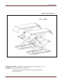
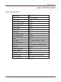
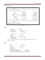
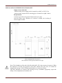
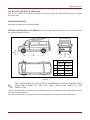
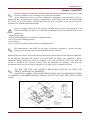
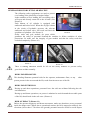
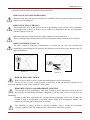
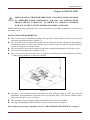
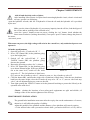
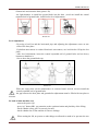
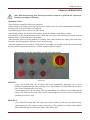
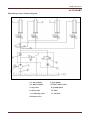
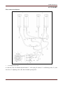
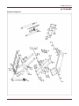
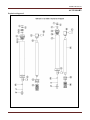
USER‟S MANUAL UNICO USER‟S MANUAL Operation Manual & Instruction SCISSOR LIFT (MODEL: GC-3.0SL) 1 USER‟S MANUAL SMALL SCISSOR LIFT GC-3.0SL MANUFACTURER: Guangzhou Gaochang Hydraulic Technology Co. Ltd. ADDRESS: Huangqishan Road, Yonghe Zone, Guangzhou Economic & Technologic Development District, 511356 P.R.China 2 USER‟S MANUAL CONTENTS Packing, transport and storage……………………………………………………………….4 Introduction……………………………………………………………………………………6 Chapter 1 Description of the machine……………………………………………………..…7 Chapter 2 Specifications………………………………………………………………………8 Chapter 3 Safeties………………………………………………………………………….…12 Chapter 4 Installation……………………………………………………………………...…17 Chapter 5 Adjustments…………………………………………………………………….....20 Chapter 6 Operations………………………………………………………………………....23 Chapter 7 Maintenance and care……………………………………………….……….…...25 Chapter 8 Failures and resolutions………………………………...……………………...…26 Chapter 9 Accessory …………………………………………………………………….……27 3 USER‟S MANUAL PACKING, TRANSPORT AND STORAGE PACKING, TRANSPORT AND STORAGE ALL PACKING, LIFTING, HANDLING, TRANSPORT AND UNPACKING OPERATIONS ARE TO BE PERFORMED EXCLUSIVELY BY EXPERT PERSONNEL PACKING (Picture 1) Standard equipment oil line and accessory (1# CTN), main and sub beam (2# CTN), control box (3# CTN), front board (4# CTN),cover board (5#) total is 5 pieces. Packing List N0: Name 1 Oil and accessory 2 3 4 5 Lift beam Control box Sliding board Back stop board Accessory name M16 ground bolt φ6×φ4×1000mm air pipe φ6×φ4×2200mm air pipe φ6×φ4×5400mm air pipe φ8×φ5×3000mm air pipe Three-way air pipe fitting 1.5mm2 multicore wire 5m φ14 combined cushions Tie-strip φ6 knee-way air pipe fitting High pressure pipe 860mm High pressure pipe 5400mm M8 ground bolt Maintenance and use manual Exchange fitting Rubber cushion 80×120×180 Both main beam and sub beam Sliding board Pin 720mm 750mm 1000mm 635mm 250mm directly knee Quantity 12sets 1set 1set 1set 1set 2ps 1set 4ps 15ps 1ps 6ps 3ps 32sets 1ps 1ps 4ps 2ps 1ps 4ps 4sets 1ps 2ps 2ps 2ps 1ps Table 1 4 USER‟S MANUAL PACKING, TRANSPORT AND STORAGE Packing dimension picture Picture 1 Transport (Picture 2) Packing can be lifted or moved by lift trucks, cranes or bridge cranes. In case of slinging, a second person must always take care of the load, in order to avoid dangerous oscillations. During loading and unloading operation, goods must be handled by vehicles or ships. At the arrival of the goods, verify that all items specified in the delivery notes are included. In case of missing parts possible defects or damage due to transport operations. If finding missing parts, possible defects or damage due to transport, one should examine damaged cartons according to <<Packing List.>> to verify the condition of damaged goods and missing parts, also the person in charge or the carrier must be immediately informed. The machine is heavy goods! Don‟t take manpower load and unload and transporting way into consideration, the safety of working is important. Furthermore, during loading and unloading operation goods must be handled as shown in the picture. (Picture 2) Picture 2 Storage: -The machine equipment should be stocked in the warehouse, if stocked outside should do the disposal well of waterproof. -Use box truck in the process of transport, use container storage when shipping. -The control box should be placed perpendicularly during the transport; and prevent other goods from extrusion. -The temperature for machine storage: -25ºC-- 55ºC 5 USER‟S MANUAL INSTRUCTION This manual has been prepared for workshop personnel expert in the use of the lift operator and technicians responsible for routine maintenance fitter. Workers should read the <<Maintenance & Use Manual>> carefully before carrying out any operation with the lift. This manual contains important information regarding: - The personal safety of operators and maintenance workers. - Lift safety, - The safety of lifted vehicles CONSERVING THE MANUAL This manual is an integral part of the lift. The manual must be kept in the vicinity of the lift, so that the operator and maintenance staff must be able to locate and consult the manual quickly and at any time. Attentively reading Chapter 3, which contains important information and safety warning, is particularly recommended. The lift is designed and manufactured according to European Standard The lifting, transport, unpacking, assembly, installation, starting up, initial adjustment and testing, extraordinary maintenance, repair, overhauls, transport and dismantling of the lift must be performed by specialized personnel from the licensed dealer authorized by the manufacturer. The manufacturer declines all responsibility for injury to persons or damage to vehicles or objects when any of the above mentioned operations has been performed by unauthorized personnel or when the rack has been subject to improper use. This manual indicates: the operative and safety aspects that may prove useful to the operator and maintenance worker. For better understanding the structure and operation of the lift and for best use of the same, workers must read the <<Maintenance & Use Manual>> carefully before carrying out it. In order to understand the terminology used in this manual, the maintenance and repair activities, the ability to interpret correctly the drawings and descriptions contained in the manual and be the country in which the machine has been installed. The same applies to the maintenance and the maintenance fitter must also possess specific and specialized knowledge both in mechanical and engineering field. OPERATOR: person authorized to use the lift MAINTENANCE FITTER: person authorized for routine maintenance of the lift. Manufacturer owns the right to make little change for the manual owing to the improvement of technology. 6 USER‟S MANUAL Chapter 1 DESCRIPTION OF THE MACHINE Machine Application: Small platform profile scissor lift can lift each kind of vehicle whose weight is less than 3000kg, suitable for use in vehicle tests, maintenance and caring for automobiles, which is particularly suitable for use in the basement or on the floor, without construction and hole. Structure Features: -use hidden and thin scissor structure, dispense with construction and ground hole, the occupation is small -independent control box, low-voltage controlling, good security -hydraulic cubage and in-phase cylinder, the synchronization of platform -own the double safety equipment of hydraulic lock and mechanical pawl, on the safe side -Own protection of safety valve and burst-proof equipment for hydraulic failure and over loading. So when the oil pipe bursts, the machine will not fall quickly. -use high quality hydraulic or electric element parts made in Italy, Germany, Japan and so on. -Own manual lowering operation when the power is cut. Equipment: -machine basement (The position and space of equipment installation) -machine frame (The main structure of lift and insurance institution) -Control box (Machine-controlled part) Basic structure The machine basement is made of cement and concrete Frame Make of steel connecting rod, main lifting platform, sliding board, pneumatic double tooth ,hydraulic oil tank. Control box Under the control box is hydraulic oil tank and hydraulic pump, valve and other control system. On the control box is electrical system. Scissor lift is designed and built to lift all kinds of vehicles, all other use are unauthorized. In particular, the lift is not suitable for washing spray work. And not lift the vehicle whose weight exceeds the maximum weight. 7 USER‟S MANUAL Chapter 2 SPECIFICATIONS Main technical parameter Machine type 3.0T Drive Electrical hydraulic Max lift weight 3000kg 电动液压 Main machine lift height 1830mm 3000kg Platform initial height 105mm Platform length 105mm 1450mm Platform width 1450mm 635mm Lifting time ≤50s Descent time ≤60s Whole machine length 2040mm Whole machine width 1990 mm Weight 850kg Power supply AC 400Vor230V±5% Whole machine power 2.2kw Hydraulic oil 50Hz to wearable hydraulic oil 2.2kw 12L corresponds Air pressure 6-8kg/cm2 Working temperature 2 5-40℃ 6-8kg/cm Working humidity 30-95% 5-40℃ Noisy level < 76db 30-95% Installation height < 76db height above sea level≤1000M Storage temperature 海拨≤1000M -25℃~55℃ 50Hz AC 400V 或 230V±5% Table 2 -25℃~55℃ 8 USER‟S MANUAL Lift dimension picture: Picture 3 Motor Type……………………Y90L Max power…………… 2.2kw Max voltage……………AC 400 or 230V ±5% Max electricity…………… 400V:5A ………………230V:10A Max Frequency……………50Hz Poles…………………… 4 Speed…………………1450rpm/min Building shape…………………… B14 Insulation class…………………………F When connecting the motor refer to the enclosed diagrams, and the motor direction is clockwise. Pump Type……………………………P4.3 Model…………………………gear pump Max flux…………………4.3cc/r Joint type………………………joint Overfull valve Continuous working pressure………………210bar Intermittent working pressure…………150~300bar Inject 20 litters of wearable hydraulic oil into the oil tank. 9 USER‟S MANUAL INSTALLATION SCHEME FOR SCISSOR LIFT Supply at the same time -connect to the power supply jack of control box (400V or 230V 15A) -connect to the compressed air-entering pipe of control box (ф 8×6mm) Requirements: Concrete type 425#, the period of desiccation is 15 days clean the basic layer, thickness of concrete≥150mm, the leveling of whole length≤10mm Picture 4(Equipment basic picture) The control box can be placed on the left or right Note: The foundation of the end of the lift platformP1, P2 is the structure of concrete. When the thickness of inside level ground is less than 150mm, the end of P1, P2 should be irrigated the acreage: 2500×2500mm and thickness of concrete≥150mm The basic thickness of concrete and leveling are keys, shouldn‟t egregiously expect the ability of level adjustment of machine-self. 10 USER‟S MANUAL TYPES OF VECHLES SUITABLE FOR: This lift are suitable for virtually all vehicles with total weight and with dimensions not exceeding the below data. MAXIMUM WEIGHT Maximum weight not exceed than 3000Kg THE MAX DIMENSION OF VEHICLE: The following diagrams illustrate criteria used to define the operating limits of the lift. 3.0 T Min. (mm) Max. (mm) A 1900 4000 B 100 C D 1900 900 Picture 5 THE LOWER PARTS OF THE VECHILE UNDERBODY COULD INTERFERE WITH STRUCTURAL PARTS OF THE LIFT, TAKE PARTICULAR PARTS OF THE SPORTS-CAR. The lift will also handle customized or non-standard vehicles provided they are within the maximum specified carrying capacity. Also the personnel safety zone must be defined in relation to vehicle with unusual dimensions. 11 USER‟S MANUAL Chapter 3 SAFETIES Read this chapter carefully and completely since important information for the safety of the operator or others in case of improper use of the lift is included. In the following text there are clear explanations regarding certain situations of risk or danger that may arise during the operation or maintenance of the lift, the safety device installed and the correct use of such systems, residual risks and operative procedures to use (general specific precautions to eliminate potential hazards). Lifts are designed and built to lift vehicles and hold them in the elevated position in an enclosed workshop. All other uses of the lifts are unauthorized. In particular, the lifts are not suitable for: -washing spray work; -creating raised platforms for personnel or lifting personnel; -use as a press for crushing purposes; -use as elevator; -use as a lift jack for lifting vehicle bodies or changing wheels. The manufacturer is not liable for any injury to persons or damage to vehicles and other property caused by the incorrect and unauthorized use of the lifts. During lifting and descent, the operator must remain in the control station as the diagrams illustrated. As the diagrams illustrated: the presence of persons inside the danger zone indicated is strictly prohibited. During operations persons are admitted to the area beneath the vehicle only when the vehicle is already in the elevated position, when the platforms are stationary, and when the mechanical safety devices are firmly engaged (eg : the safety gear is completely locked). DO NOT USE THE LIFT WITHOUT PROTECION DEVICES OR WITH THE PROTECTION DEVICES INHIBITED. FAILURE TO COMPLY WITH THESE REGULATION CAN CAUSE SERIOUS INJURY TO PERSONS, AND IRREPEARABLE DAMAGE TO THE LIFT AND THE VEHICLE BEIN LIFED. Picture 6 12 USER‟S MANUAL GENERAL PRECAUTIONS The operator and the maintenance fitter are required to observe the prescriptions of safety regulation in force in the country of installation of the lift. Furthermore, the operator and maintenance fitter must: -always work in the stations specified and illustrated in this manual; -never remove or deactivate the guards and mechanical, electrical, or other types of safety devices; -read the safety notices placed on the machine and the safety information in this manual. In the manual all safety notices are shown as follows: WARNING: indicates following operations that are unsafe and can cause minor injury to persons and damage the lift, the vehicle or other property. CAUTION: indicates possible danger that can result in serious injury to people and damage property. RISK OF ELECTRIC SHOCK: a specific safety notice placed on the lift in areas where the risk of electric shock is particularly high. RISK AND PROTECTION DEVICES We shall now examine the risks that operators or maintenance fitters may be exposed to when the vehicle is standing on the platforms in the raised position, together with the various safety and protection devices adopted by the manufacturer to reduce all such hazards to the minimum: For optimal personal safety and safety of vehicles, observe the following regulations: -do not enter the safety and safety of vehicles are being lifted. (Picture 6) -make sure the vehicle is positioned correctly. (Picture 7) -be sure to lift only approved vehicles, never exceed the specified carrying capacity, maximum height, and projection (vehicle length and width); -make sure that there is no person on the platforms during up and down movements and during standing. Picture 7 13 USER‟S MANUAL GENERAL RISKS FOR LIFTING OR DESCENT: The following safety equipments are used to protect over loading or the possibility of engine failure. In the condition of over loading, the over-falling valve will open and directly return oil to the oil tank. (See Picture 8) Each bottom of oil cylinder is equipped with antiknock and locked valve. When the oil pipe is burst in the circuit of hydraulic pressure, the relevant antiknock and locked valve will work and limit the speediness of platform. (See Picture 9) Picture 8 Safety tooth and gear module are parts which guarantee the safety of personnel beneath the machine in failure condition of other protections. So make sure the integrity of gear module and that the safety tooth has occluded completely. (Picture 10) Picture 9 Picture 10 There is nothing abnormal should be left on the safety modules to prevent safety gear from occlude normally. RISKS FOR PERSONNEL This heading illustrates potential risks for the operator, maintenance fitter, or any other person present in the area around the lift, result from incorrect use of the lift. RISKS FOR EXTRUSION During up and down operations, personnel leave the said area without following the rule and instruction. During up and down operations, no person is admitted to work beneath the movable parts of the lift, should work in the safe zone. (Picture 6) RISK OF IMPACT (Picture 11) Before the operator begins up and down movements, make sure that there are no personnel inside the danger zone. When, due to operational reasons, the lift is stopped at relatively low elevations (lower than 1.75m above the ground) personnel must be careful to avoid impact 14 USER‟S MANUAL with parts of the machine not marked with special colors. RISK OF FALLING OFF (PERSONNEL) During up and down operations, personnel are prohibited from entering the platforms and the vehicle to avoid falling off. RISK OF FALLING (VEHICLE) This hazard may arise in the case of incorrect positioning of the vehicle on the platforms, overweight of the vehicle, or in the case of vehicles of dimensions that are not compatible with the capacity of the lift. When the platform is being tested, the vehicle engine can not be turned on. There is nothing should be placed on the lift-lowering area and the movable parts of the lift. RISK OF SLIPPINE (Picture 12) The floor caused by lubricant contamination of around the lift. The area beneath and immediately surrounding the lift and also the platforms must be kept clean. Remove any oil spills immediately. Picture 11 Picture 12 RISK OF ELECTRIC SHOCK Risk of electric shock in areas of insulated and shattered electric equipments. Do not use jets of water, steam solvents or paint next to the lift, and take special care to keep such substances clear of the electrical control panel. RISKS RELATED TO IMAPPROPRIATE LIGHTING The operator and the maintenance fitter must be able to assure that all the areas of the lift are properly and uniformly illuminate compliance with the laws in force in the place of installation. During up and down operations, the operator should continually observe the lift and can operate it only in the position of operator. When lifting and lowering the vehicle, the cushion needs being put in the bottom of chassis. The handling of safety devices is strictly forbidden. Never exceed the maximum carrying capacity of the lift, make sure the vehicles to be lifted have no load. 15 USER‟S MANUAL It is therefore essential to adhere scrupulously to all regulations regarding use, maintenance and safety contained in this manual. 16 USER‟S MANUAL Chapter 4 INSTALLAION SKILLED AND AUTHORIZED PERSONNEL ONLY SHOULD BE ALLOWED TO PERFORM THESE OPERATIONS, FOLLOW ALL INSTRUCTIONS SHOWN BELOW CAREFULLY, IN ORDER TO PREVENT POSSIBLE DAMAGE TO THE CAR LIFT OR RISK OF INJURY TO PEOPLE. Skilled technicians only appointed by the same manufacturer or by authorized dealers, are allowed to install the car lift. INSTALLATION REQUIREMENTS The car lift must be installed according to the specified safety distances from walls, pole and what other equipments stated. (Picture 13) The specified safety distances from walls must be 1000 mm at least, taking into consideration the necessary space to work easily. Because space for the control site and for possible runways in case of emergency is also necessary. The room must be previously arranged for the power supply and pneumatic feed of the car lift. The room must be 4000 mm in height, at least. The car lift can be placed on any floor, as long as it is perfectly level and sufficiently resistant. (≥250kg/cm²,the thickness of concrete≥150mm) Picture 13 All parts of the machine must be uniformly lit with sufficient light to make sure that the adjustment and maintenance operations can be performed safely, and without reflected light, glare that could give rise to eye fatigue. The integrality of arrived goods should be checked before the lift is installed. Moving and installing lift should follow the process as the picture instructs. The transport and storage of machine refers to “TRANSPORT AND STORAGE” on page **. 17 USER‟S MANUAL Chapter 4 INSTALLAION Platform Installation: -Place two lift platforms on the position of the location -The bottom of oil cylinder is located in the frontage of machine (the direction of getting on the vehicle) -Use fork car or other lifting equipments to lift the platform (Picture14) and make sure that the safety equipment of machine is both turned on and locked. To avoid failure of machine safety equipment, can insert a wood in the middle part of joint-pole. Prohibit working beneath the lift when hydraulic system is not completely equipped with hydraulic oil and take the Picture 14 action of up and down operations. -When moving the lift platform, adjust the space between two platforms, make sure that the two platforms are parallel. LINE CONNECTION Connect the electrical and oil line according to <<the electric wiring diagram>> and <<oil line connection>>. Only after connecting the hydraulic system can connect the air loop, can not damage oil pipe, wire, and air pipe. In the process of connecting oil pipe and air pipe, pay particularly attention to the protection of pipe tie-in to prevent abnormal thing from entering oil loop and air loop, then damaging hydraulic system. ELECRIC CIRCUIT CONNECTION: Follow the stated line- pathway and line-number of <<the electric wiring diagram>> to connect electric circuit. Only skilled person is allowed to perform the operations. - open the control box front cover -connection of power supply: the 400V three-phase and five-line connection wires (3×2.5mm2 +2×1.5 mm2 cable wire) for power supply are connected to control box L1,L2,L3,N and entering-wire terminal. The PE ground wire is connected under the bolt marked ground firstly (Picture 15) and then connected under the bolt marked ground of two platforms. -If the lift is operated at 230V three-phase, change the connection on the transformer and motor. (Picture 16) Picture 15 Picture 16 18 USER‟S MANUAL HYDRAULIC PIPELINE CONNECTION: Follow <<oil line diagram >> to connect the hydraulic oil pipes Only skilled and authorized person is allowed to perform the operations. And pay particularly attention to the protection of vita head. -Following vita number to lead the high-pressure vita out from the “working stop valve G” and two “oil make-up stop valve H, I” of control box and then connect it to oil cylinder. (Refer to <<oil line diagram>>) -when connecting vita, pay attention to the protection of vita tie-in to prevent impurities from entering hydraulic circuit. When connecting the vita, be care of the mistake of each vita number. During the standard installation, control box is in the nearside of vehicle-entering direction. If placed on the right should adjust relevant vita. COMPRESSED AIR PIPE CONNEVTION: Follow <<air loop diagram >> to connect air loop Only skilled and authorized person is allowed to perform the operations. -Connect Φ8×6 compressed air supply pipe to the air supply jaws of pneumatic electromagnetic valve inside the control box. (Picture17) -Follow <<air loop diagram >> to lead the compressed air pipe out from pneumatic electromagnetic valve and then connect it to the uplifted-pawl air valve. (Picture 18) -Pay attention to the protection of windpipe tie-in to prevent impurities from entering compressed air circuit. -Connect compressed air pipe to the extra-installed grease separator which is in front of control box to prolong the life of pneumatic components and the reliability of action. In the process of windpipe installation, the windpipe can not be folded or tied to avoid that the air loop is not smooth or it is jammed. Before leading the compressed air supply pipe to the air supply jaws of pneumatic electromagnetic valve inside the control box, should extra install grease separator to separate compressed air, avoiding the failure of pneumatic cell action. Picture 17 Picture 18 19 USER‟S MANUAL Chapter 5 ADJUSTMENTS Add oil and check the order of phase. After installing lift as Picture 4 required and connecting hydraulic circuit, electric circuit and air loop, operate it as following: -open the hydraulic oil tank, add 18L of hydraulic oil into the oil tank, the hydraulic oil is provided by the user. Make sure the clean of hydraulic oil, prevent any impurity into the oil line, lead the digest of the oil line and no working of the solenoid valve. -press the “power” button to turn on power, clicking the “up” button, check whether the motor turns clockwise (looking downward), if not press “power” button, change the phase of the motor. -turn on air power When turn on power, the high voltage will exist in the control box, only authorized person can operate it. Oil make-up adjustment 1. Open the stop valve „G‟and valve„H‟ „I‟ 2. Press “UP” button SB1; let the platform going up to the height place. 3. Switch off the valves„H‟and „I‟, press „DOWN‟ button SB2; the platform going down to the ground. 4. Repeat the operation as above for 3~4 times. 5. Press „UP‟ button SB1, let the platform going up to about 500mm height. If the two platform Picture 19 not at the same level, switch off „the work stop valve G‟. The left platform is little lower (P1), turn on „the oil make-up valve I‟, otherwise, turn on „ the oil make-up valve H‟ 6. Click the button SB1, and then the single side of platform is lifted alone. After the two platforms both have the same height, close the oil make-up stop valve “H” or “I”, turn on “the work stop valve”, the oil adjustment process comes to the end. 7. Turn right opening the “PHOTO” button to let the photocell working to protect the lift only to be operated at the same level. Check: whether the locations of two safety-pawl equipments are agile and reliable, oil leakage of the oil line and air tightness of the air loop. GROUND BOLTS INSTALLATION: The ground bolts installation must start after the expiry date on the maintenance of concert, otherwise, it will affect the quality of solidity. -adjust the parallel of the platform and the distance of two platform as Picture 4 requires. - fix the anchor bolts with a percussion electric drill ( percussion drill bit is of 16), drill to 20 USER‟S MANUAL 120mm hole and clean the hole.(picture 20) -use light hammer to install the ground holts into the hole ( need not install the central expanded nail of ground bolts, install it after level adjustment.) Picture 20 Level adjustment: - By using a level bar and the horizontal pipe and adjusting the adjustment screws at tow sides of the base plate. -If platform unevenness is resulted from basic unevenness, use iron block to fill up the low place. -After level adjustment, insert the central expanded nail of ground bolts and use heavy hammer to hammer it. -Screw down the ground bolts cap Picture 21 When the expiry date on the maintenance of concrete hasn‟t arrived, can not install the central expanded nail of ground bolts. the gap between the base plate and ground after adjustment must be filled with iron plate or concrete. No load of main machine test: -turn on the power QS. -press “up” button SB1, pay attention to the synchronization and placidity of the lifting. -check whether safety pawl is correctly located. -check whether the oil line and the air line are leakage. When testing the lift, no person or other things are allowed to stand or be put near the two 21 USER‟S MANUAL sides and beneath the machine. If any abnormal is found, press button “SB0” to stop it timely. After clearing obstacles, do the test again. Load of machine test: -Drive the vehicle whose weight doesn‟t exceed maximum lift weight to the platform, and then the driver leave it. -Put the lift rubber cushion on the nuchal-seat. -press “up” button SB1, lift the platform and pay attention to the synchronization and placidity of the lifting. -check whether safety pawl is correctly located. -check whether the oil line and the air line are leakage. When beginning load of machine test, no person or other things are allowed to stand or be put near the two sides and beneath the machine. Test vehicle whose weight doesn‟t exceed maximum lift weight. Check whether the oil line and the air line are leakage. If any abnormal is found, press button “SB0” to stop it timely. After clearing obstacles, do the test again. 22 USER‟S MANUAL Chapter 6 OPERATIONS Only skilled and having been trained personnel is allowed to perform the operations. Check proceedings as following. Operation Notices: -clear obstacles around the lift before operation. -during lifting or lowering, no person is allowed to stand neat the two sides and beneath the machine, and no person is allowed on the two platform. -avoid lifting super heavy vehicles or other goods. -when lifting vehicle, the chassis of the vehicle should be filled up with rubber cushion. -pay attention to the synchronization of the lifting and lowering. If any abnormal is found, stop the machine timely, check and remove the trouble. -when lowering vehicle, lift the platform a bit firstly, notice that whether two safety pawls and safety teeth have been disengaged completely. If not, stop lowering. -when the equipment is not used for a long time or over night, the machine should be lowered to the lowest position on ground, and remove vehicle, and cut off power supply. Instructions on electric operation: (see the operation panel) Picture 22 LIFTING: -press “lift” button SB1, the oil pump will work immediately, hydraulic oil is sent to hydraulic cylinder through “the work stop valve”, the platform is being lifted and the safety pawl is also lifted because of air loop. -release button SB1, the oil pump will stop immediately, the platform stops lifting and the safety pawl falls on the safety gear because electromagnetic air-valve is out of electricity and then close the air loop. DESCENT: -press “DOWN” button SB2, the safety pawl will be lifted by joint air loop and lowering-electromagnetic valve opens because of electricity. The platform is lowing, release button SB2, stop lowering, the safety pawl falls on the safety gear. 23 USER‟S MANUAL EMERGENCY STOP: When the machine has abnormal or car maintenance, push “emergency stop” button “SB0” and locking, cut off all the operation circuit, other operation can not be work. NOT IN-PHASE STOP MACHINE: When two platforms are not at the same height during lifting and lowering operations, photo-electricity leveling equipment will stop working immediately. According to the following process to adjust the platform level, only after two platforms are at the same height can put them into use. Oil make-up “adjust” operation (normal service period): After completion of machine installation and adjustment in the application process, the right platform is lower than the left one because of air in the oil cylinder not being excluded completely normal looses or leakage of the hydraulic oil. When conducting oil make-up operation, the platforms must not be load. Adjustment process as „Oil make-up adjustment‟ approach„5‟and„6‟. EMERGENCY MANUAL OPERATION FOR LOWERING (POWER FAILURE): When lowering through manual operation, should observe the condition of platform at any time because there are vehicles on the platform. If there is something abnormal, screw down oil loop valve immediately. The process of manual operation: -firstly lift two safety pawls of platform and use thin iron bar to fill up it. -switch off the power button (avoid abruptly incoming electricity). Open the back cover of control box to find the electromagnetic valve A for lowering. Picture 23 -loosen manual oil loop stud at the end of lowering electromagnetic valve core, then the platform begins lowering. -after the machine has been lowered, screw down manual oil loop stud timely, the process of manual lowering comes to the end. 24 USER‟S MANUAL Chapter 7 MAINTENANCE AND CARE Skilled personnel only is allowed to perform the operations. -all bearings and hinges on this machine must be lubricated once a week by using an oiler. -the safety gear, the upper and lower sliding blocks and other movable parts must be lubricated once o month. -the hydraulic oil must be replaced one time each year. The oil level should always be kept at upper limit position. The machine should be lower to the lowest position when replace hydraulic oil, then let the old oil out, and should be filter the hydraulic oil. -Each team checks the agility and reliability of pneumatic safety equipment. 25 USER‟S MANUAL Chapter 8 FAILURE AND RESOLUTIONS Skilled personnel only is allowed to perform the operations. Failure Phenomena and Resolutions Failure Phenomena The motor does not run in lifting operation. ① In lifting operation, the motor runs, but there is no lifting movement When press “Lower” button, the machine is not lowered The machine lowers extremely slowly under normal loads. The right and left platforms are not synchronous and not in the same height. Noisy lifting and lowering. Cause and Phenomena Resolutions ① Connection of power supply wires is Check and correct wire connection not correct. If the motor operates when forcing the contactor down with an ② The AC contactor in the circuit of isolation rod, check the control circuit. If the voltage at two ends the motor does not pick up. of the contactor coil is normal, replace the contactor. Check the limit switch, wires and adjust or replace the limit The limit switch is not closed. switch. ① The motor turns reverse. Change the phases of the power supply wires. The set safe pressure of the over-flow valve may be increased by ② Lifting with light load is normal but turning the set knob right ward slightly. no lifting with heavy load. The spool of the lowering solenoid valve is stuck by dirt. Clean the spool. ③ The amount of hydraulic oil is not Add hydraulic oil. enough. ④ The “operation stop valve” is not Screw down the “Operation stop valve”. closed. ① The safety pawl are not released form First lift a little and then lowering the safety teeth. The air pressure is not enough, the safety pawl is stuck or the air ② The safety pawl is not lifted. pipe is broken off, adjust pressure, check the air pipe and replace it. ③ The solenoid air valve does not If the solenoid air valve is energized, but does not open the air work. loop, check or replace the solenoid air valve. ④ The lowering solenoid valve is Check the plug and coil of the lowering solenoid valve and check energized but does not work. the right turn tightness of its end copper nut and so on. Remove the “antiknock valve” from the oil supply hole at the ⑤The “antiknock valve” is blocked. bottom of the oil cylinder, and clean the “antiknock valve”. ①The hydraulic oil has too high Replace with hydraulic oil in accordance with the instruction viscosity or frozen, deteriorated (in book. Winter). Remove or close air supply pipe and thus lock the safety pawl of ② The “antiknock valve” for the machine without lifting of the safety pawl. Remove the preventing oil pipe burst is blocked. “antiknock valve” from the oil supply hole at the bottom of the oil cylinder, and clean the “antiknock valve”. ① The air in the oil cylinder is not vent Refer to “Ⅶ. Oil Make-up „Adjust‟ Operation”. completely. ② Oil leakage on oil pipe or at its Tighten oil pipe connections or replace oil seals and then make-up connections. oil and adjust levelness. ③ The “oil make-up stop valve” can not be closed tightly and almost Replace oil make-up stop valve, and then make-up oil and adjust. make-up oil and adjust every day. Lubricate all hinges and motion parts (including piston rod) with ①Lubrication is not enough. machine oil Adjust again the levelness of the machine, and fill or pad the ② The base or the machine is twisted. base. Table 3 26 USER‟S MANUAL ACCESSORY Hydraulic pressure elements diagram 1.3. sub cylinder 9. gear pump 2.4. main cylinder 10. flow control valve 5. stop valve 11. pump motor 6. check valve 12. filter 7. overflowing valve 13. oil tank 8. descent valve 27 USER‟S MANUAL ACCESSORY Hose connection diagram 1. 1#~9# high pressure pipe A: descent valve; B: manual descent knob; C: valve plug; D: motor; E: overflowing valve; F: joint wire box; G: adjusting valve; H,I: the oil make-up stop valve 28 USER‟S MANUAL ACCESSORY Explosion diagram 1 29 USER‟S MANUAL ACCESSORY Explosion diagram 2 30


![Installation Manual [PDF 3.1 MB]](http://vs1.manualzilla.com/store/data/006000040_1-a740b84bcdd0f591a4a671097fdfa72a-150x150.png)