1
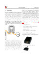
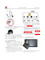
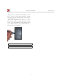
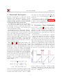
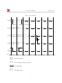
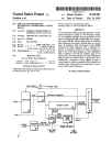
interX User Manual
Revision 0.1.4
XDIMAX Ltd
October 18, 2007
1
interX User Manual
Contents
1 Overview
1.1 Key Features . . . . . .
1.2 interX Package Content
1.3 interX Front Panel . . .
1.4 interX Bottom Side . . .
.
.
.
.
.
.
.
.
.
.
.
.
.
.
.
.
3
3
3
4
4
2 Functional Description
2.1 Precision vs. Power Consumption
2.2 RS232 Terminal . . . . . . . . . .
2.2.1 RS232 Port Settings . . .
2.2.2 ’p’ Command . . . . . . .
2.2.3 ’o’ Command . . . . . . .
2.2.4 ’c’ Command . . . . . . .
2.2.5 ’s’ Command . . . . . . .
2.2.6 ’g’ Command . . . . . . .
2.3 Low Battery State . . . . . . . .
2.4 LED Indicator . . . . . . . . . .
.
.
.
.
.
.
.
.
.
.
.
.
.
.
.
.
.
.
.
.
.
.
.
.
.
.
.
.
.
.
6
6
8
8
8
8
8
8
9
9
9
3 Electrical Characteristics
3.1 Power Supply Adapter Requirements .
10
10
.
.
.
.
.
.
.
.
.
.
.
.
.
.
.
.
2
Revision 0.1.4
interX User Manual
1
Overview
Revision 0.1.4
number of days. During all this period synchronization between units will stay unchanged. In other
words there will be no timing drift between units.
interX can be widely used in many other applications that require synchronous operations spread over
wide geographical area. Operations themselves are
not only limited to short/open shunt. interX has I/O
ports and optional peripheral devices (like analog to
digital and digital to analog converters, non volatile
memory, current monitor, Infrared transceiver) that
can be programmed to perform desired complex operation.
For better understanding of interX functionality
and abilities please read Section Functional Description
interX was originally developed as a measurement
instrument for industrial and trunk pipeline anodic
or cathodic protection systems. interX allows facilitate measurement of galvanic parameters (instant-off
polarized potentials, pipe-to-soil potential) across a
wide range of timing cycles. It is used to make synchronous disconnect and reconnect of protection electrodes (anode or cathode) or rectifiers from/to buried
underground pipeline to perform measurements. Required number of interX interrupters can be installed
over miles of pipeline without any distance or line of
sight limitations. Being programmed to the desired
on/off time intervals all units will synchronously perform the same operation cycles over predefined period
of time.
1.1
Key Features
• Under 1 millisecond unit to unit divergence
• Max switching power 60W
• Battery operated
• Easy configurable via RS232 terminal
1.2
interX Package Content
Standard interX package contains following items:
• interX device
The picture above shows how interX can be connected to pipeline anti-corrosion protection circuit.
Having a number of interX being connected the same
way to electrodes over the pipeline and one connected
to the rectifier you will get ultimate solution to make
required measurements of the anti-corrosion protection system parameters. All interX devices will disconnect electrode or rectifier from the pipeline exactly at the same time and will connect them back
again exactly at the same time. This will continue
during whole measurement period that can lasts a
• GPS Antenna with 5m coaxial cable
3
interX User Manual
Revision 0.1.4
• RS232 Cable
• Two Shunt Cables
RS232 Terminal output is used to connect interX
to PC RS232 port. Additional information
about interX RS232 terminal can be found in
Section RS232 Terminal .
For non battery driven applications interX package
will contain AC-DC power supply adapter
DC Input is used for connecting external power
supply adapter in non battery driven mode.
Power supply adapter is provided in interX package. If you are going to use your own power
supply please look at the Section Power Supply
Adapter Requirements .
• AC-DC Power Supply Adapter
LED is a small red light indicator. Information
about it can be found in Section LED Indicator
.
The exact interX package content is subject to
change. It can be extended for customized interX
version. Please contact XDIMAX or it’s representatives to get up to date information and/or request
extensions to standard package.
1.3
1.4
interX Bottom Side
interX Front Panel
Shunt Outputs are connected to latch relay. Shunt
Outputs can be closed (short connected to
each other) or open (disconnected from each
other). For pipeline trunk measurement shunt
outputs may be connected between electrode and
pipeline or electrode and ground.
Antenna Connector is used to connect GPS antenna provided in interX package. GPS antenna
has 5 meters coaxial cable. It has to be mounted
in open space to increase interX precision and
On bottom side of interX there are battery holder
reduce power consumption.
compartment and on-off push button.
4
interX User Manual
Battery holder compartment has sliding cover that
can be opened to replace interX batteries. In time
of normal operation to transportation battery holder
cover should be closed.
The on-off countersunk push button on bottom
side is used to turn on or turn off interX . Button
can not be pressed with finger but requires pointed
object. While button is pressed LED Indicator on
front panel is unconditionally on
To turn interX on press button for at least 4 seconds
To turn interX off press button for at least 2 seconds
5
Revision 0.1.4
interX User Manual
2
Functional Description
Revision 0.1.4
next PPS period CPU will get new GPS Time (increased by one second) and will take new decision.
And so on . . .
Parameters T c and T o are configurable. They can
be set via RS232 terminal (Section RS232 Terminal
). Time resolution (granularity) for T c and T o in
standard interX configuration is 1sec.
interX is an integration of powerful I/O controller
and GPS module. This internal structure of interX
defines its main functionality - “Perform I/O operations in high precision real time moments
synchronous with other interX units”.
In default interX configuration I/O operation is to
open or short-circuit shunt outputs. Shunt outputs
are internally connected to latch relay. interX CPU
provides high or low signal to relay and thus opens
or short-circuit shunt outputs.
interX timing is based on GPS outputs. GPS provides real time information - GPS Time and PulsePer-Second (PPS) signal. PPS is four microsecond
wide positive pulse synchronized with respect to UTC
(Universal Coordinated Time). The PPS timing accuracy is ±50ns when valid position fixes are being
reported. GPS Time is a number of seconds elapsed
from the January 6, 1980. Based on GPS Time and
PPS interX CPU can decide what I/O operation to
perform and when exactly
Figure 1 on page 7 illustrates functionality of the
four interX units set. Each unit is powered up at
some moment. After power up unit waits for GPS
initialization. GPS is considering fully functional after it starts to make position fixes. It means GPS
can calculate it’s position coordinates and all timing
information is at maximum precision. GPS initialization time depends on many factors. In general GPS
module has to get tracking of at least 4 satellites to
start doing position fixes. After GPS is on and “doing position fixes” interX CPU can start operations.
Decision to open or close shunt relay at every specific
moment is taken by CPU according to the following
simple formula:
2.1
Precision vs. Power Consumption
As you can see on figure 1 T d denotes possible divergence between two interX units. In non battery
driven mode or without entering power saving mode
interX T d depends on PPS precision (±50ns) and
CPU interrupt latency (120 ± 60ns) and totally can
be less then 230ns.
In battery driven mode interX can be configured
to enter power saving mode to reduce total power
consumption and increase work time before changing
or recharging battery. In power saving mode interX
CPU temporary turns off GPS module and use it’s
own clock for synchronization. After T s minutes GPS
is turned on for minimal time required to synchronize
CPU clock with PPS. Because CPU clock is not as
stable as PPS signal the more time GPS is off and
CPU clock is used the bigger divergence will grow
up. From the other side the longer GPS module is
P hase = GP S T ime mod (T o + T c)
Output =
closed
open
if P hase < T c
if P hase >= T c
powered off the less power will be consumed by unit.
Configurable parameter T s - time the GPS module
After decision is taken actual signal to shunt relay will can be powered off defines trade-off between precision
be strobed by following PPS signal. This way high and power consumption.
precision synchronization will be achieved. Within
T c,T o - Closed,Open Time (sec)
6
interX User Manual
Revision 0.1.4
Figure 1: interX timing
Unit1
....VVVVVVVVVVVVVZUZZZZZUZZZZZUZZZZZUZZZZZUZZZZZ
GPS Doing Position Fixes
Power UP
Unit2
Unit3
Unit4
...............VVVVVVVVVVZZZUZZZZZUZZZZZUZZZZZUZZZZZ
......................VVVVVVVVVZZZZZUZZZZZUZZZZZUZZZZZ
Td
Aaaa
...............VVVVVVVVVVZZZUZZZZZUZZZZZUZZZZZUZZZZZ
To
aaP
aaaaaaP
SHUNTUZZZZZUZZZZZUZZZZZUZZZZZUZZZZZUZZZZZUZZZZZ
bBBBBBBBBBBBBBBBBBBBBBBBBBBBBBBBBBBBBBBBBBBBBBBBBBBBBBBBBBBBBBBBBBBBBBBBB
PPS
Tc
N
N+10
N+20
N+30
-....- Unit Powered Down
-VVVV- Unit Powered Up. Waiting for GPS Init
ZZZZZZShunt Relay Open
-UUUU- Shunt Relay Closed
7
N+40
N+50
N+60
N+70
interX User Manual
2.2
RS232 Terminal
Revision 0.1.4
>p
To=0A
Tc=05
Ts=03
>
interX configuration can be done via RS232 terminal
program (like HyperTerminal or Term95). Terminal
session can be started only after interX powered up.
To enter terminal session following steps required.
In this example
T o = 0A = 10sec,
T c = 5sec,
T s = 3min
1. Open Terminal program
2. Configure RS232 port (see Section RS232 Port
Settings )
3. Connect RS232 cable from interX to PC
2.2.3 ’o’ Command
SYNOPSIS
o < T ime >
4. Turn on or restart interX
5. If everything is connected and configured right DESCRIPTION
Set T o. T ime must be hex number 00 to FF
you will see in terminal window countdown from
that
denotes 0 to 255 second value.
9 to 0 (9876543210). Press ENTER before
counter gets to zero Countdown will stop, in- EXAMPLE
Set T o to 0f=15 second
terX will enter terminal session and will show
prompt character ’>’
>o 0 f
>
987654
>
2.2.1
2.2.4 ’c’ Command
SYNOPSIS
c < T ime >
RS232 Port Settings
interX requires following RS232 port settings:
Bits per second 9600
Data bits 8
Parity ODD
Stop bits 1
Flow control None
2.2.2
DESCRIPTION
Set T c. T ime must be hex number 00 to FF
that denotes 0 to 255 second value.
EXAMPLE
Set T c to 0A=10 second
>c0A
>
’p’ Command
SYNOPSIS
p
2.2.5 ’s’ Command
SYNOPSIS
s < T ime >
DESCRIPTION
Print current To,Tc,Ts settings as hexadeci- DESCRIPTION
mal numbers. To,Tc values are in seconds, Ts in
Set T s. T ime must be hex number 00 to FF
minutes.
that denotes 0 to 255 minutes value.
EXAMPLE
EXAMPLE
Set T o to 14h=20 min.
Just type ’p’
8
interX User Manual
>o14
>
Revision 0.1.4
Two Satellites Visible
LLLLLLLLLLLLLLLLLLL
TTTTTTTTTTTTTTTTTTTTTTTTTTTTTTTTTTT
ON
0s
2.2.6
1s
ON
0s
4s
1s
1s
ON
0s
Antenna not Connected or Damaged
Solid ON
VVVVVVVVVVVVVVVVVVVVVVVVVVVVVVVVV
TTTTTTTTTTTTTTTTTTTTTTTTTTTTTTTTTTT
3s
4s
None or One Satellite Visible
LLLLLLLLLLLLLLLLLLLLLLLLLLL
TTTTTTTTTTTTTTTTTTTTTTTTTTTTTTTTTTT
ON
ON
2s
2s
ON
ON
3s
4s
2s
3s
4s
LLL
TTTTTTTTTTTTTTTTTTTTTTTTTTTTTTTTTTT
interX LED provides special on/off sequences to indicate different states of the interX CPU and GPS
module. Diagrams below show LED sequences and
their meaning
1s
ON
Low Battery State
LED Indicator
2s
ON
Constantly OFF
LLLLLLLLLLLLLLLLLLLLLLLLLLLLLLLLLLL
TTTTTTTTTTTTTTTTTTTTTTTTTTTTTTTTTTT
Low Battery State
1s
ON
GPS doing position fixes
In battery driven mode interX will monitor battery
charge capacity ( supplied voltage and current) If battery charge fails below threshold required for normal
operation interX will enter Low Battery State. In this
state only LED Indicator is functional and LED will
continuously blink to indicate Low Battery State (see
Section LED Indicator ). To return interX to normal
operation it’s batteries have to be exchanged.
0s
3s
LLLLLLLLLLL
TTTTTTTTTTTTTTTTTTTTTTTTTTTTTTTTTTT
0s
0s
2s
ON
Three Satellites Visible
DESCRIPTION
End terminal session and run application. After issuing this command interX will start normal operation and will not echo or respond terminal commands
2.4
ON
’g’ Command
SYNOPSIS
g
2.3
ON
3s
4s
9
ON
ON
1s
ON
ON
2s
ON
ON
3s
ON
4s
interX User Manual
3
Electrical Characteristics
Parameter
Rating
Battery Type
Single Battery Voltage
Input DC Voltage
Precision
Shunt Relay Parameters
Contact Resistance
Switching voltage
Symbol
Vbat
Rc
Condition
Min
Battery Driven Mode
Battery Driven Mode
Power Supply Mode
Ts=0
Ts=20
1.2
5
0.1
Closing
Opening
1A 30V DC
Power Supply Adapter Requirements
Input Voltage
Output Voltage
Output Current
Polarity
Plug Type Barrel
110-120V or 220-240V
7-12V
100mA (or more)
Plus Inside (+)
5.2x2.1mm
10
Typ
Max
Units
1.7
14
0.8
30
V
V
ms
ms
75
125
220
2
60
4
4
mΩ
V
V
A
W
ms
ms
times
AA
Relay Closed
AC
DC
Switching Current
Switching Power
Set Time
Release Time
Expected life
3.1
Revision 0.1.4
2x10⁵
9
0.2