1
OPERATING MANUAL
FAULT LOOP IMPEDANCE METER
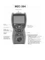
MZC-304
SONEL SA
ul. Wokulskiego 11
58-100 Świdnica
Version 1.09 27.06.2014
2
OPERATING MANUAL MZC-304 version 1.09
CONTENTS
1
SAFETY ....................................................................................................................5
2
MEASUREMENTS ..................................................................................................6
2.1
2.2
2.3
2.4
2.5
2.6
2.7
2.7.1
2.7.2
2.7.3
2.7.4
2.7.5
TURNING THE METER ON AND OFF, DISPLAY BACKLIGHT .......................................6
SELECTION OF GENERAL MEASUREMENT PARAMETERS .........................................6
REMEMBERING THE LAST MEASUREMENT RESULT ................................................7
MEASUREMENT OF ALTERNATING VOLTAGE .........................................................7
MEASUREMENT OF VOLTAGE AND FREQUENCY .....................................................8
CHECKING CORRECTNESS OF PE (PROTECTIVE EARTH) CONNECTIONS ..................8
MEASUREMENT OF FAULT LOOP PARAMETERS ......................................................9
Cable length selection....................................................................................9
Prospective short-circuit current .................................................................10
Measurement of fault loop parameters in the L-N and L-L circuits ............10
Measurement of fault loop parameters in the L-PE circuit .........................13
Measurement of short circuit loop impedance in L-PE circuit protected by a
residual current device (RCD) ......................................................................14
2.8
MEASUREMENT OF RESISTANCE TO EARTH..........................................................15
2.9
LOW-VOLTAGE RESISTANCE MEASUREMENT .......................................................16
2.9.1
Measurement of continuity of protective conductors and equipotential
bondings with 200 mA current ..................................................................17
2.9.2
Low-current measurement of resistance ......................................................18
2.9.3
Compensation of test leads resistance - autozeroing ...................................19
3
MEMORY OF MEASUREMENT RESULT DATA...........................................21
3.1
3.2
3.3
3.4
3.4.1
3.4.2
3.5
3.5.1
3.5.2
STORING THE MEASUREMENT RESULT DATA IN THE MEMORY .............................21
CHANGING THE CELL AND BANK NUMBER ...........................................................23
VIEWING MEMORY DATA.....................................................................................23
DELETING MEMORY DATA ...................................................................................24
Deleting bank data.......................................................................................24
Deleting the whole memory .........................................................................25
COMMUNICATION WITH A COMPUTER .................................................................26
Computer connection accessories ...............................................................26
Data transmission ........................................................................................26
4
TROUBLESHOOTING .........................................................................................28
5
POWER SUPPLY OF THE METER ...................................................................29
5.1
5.2
5.3
6
MONITORING OF THE POWER SUPPLY VOLTAGE ...................................................29
REPLACEMENT OF BATTERIES .............................................................................29
GENERAL RULES OF USING THE NICKEL METAL HYDRIDE (NI-MH) BATTERIES ..30
CLEANING AND MAINTENANCE....................................................................31
OPERATING MANUAL MZC-304 version 1.09
3
7
STORAGE ..............................................................................................................31
8
DISMANTLING AND DISPOSAL .......................................................................31
9
TECHNICAL SPECIFICATIONS .......................................................................32
9.1
BASIC DATA ........................................................................................................32
9.2
ADDITIONAL INFORMATION .................................................................................34
9.2.1
Additional uncertainty according to IEC 61557-3 (Z) ................................35
9.2.2
Additional uncertainty according to IEC 61557-4 (R ±200mA) ..................35
10
EQUIPMENT .........................................................................................................36
10.1
10.2
11
4
STANDARD EQUIPMENT .......................................................................................36
OPTIONAL ACCESSORIES .....................................................................................36
MANUFACTURER ...............................................................................................38
OPERATING MANUAL MZC-304 version 1.09
1
Safety
The MZC-304 meter is designed for testing the protection against electric shock in the mains systems. The meter is used to make measurements which results determine the electrical installation
safety level. Consequently, in order to ensure safe operation and correct measurement results, observe the following recommendations:
Before you proceed to operate the meter, acquaint yourself thoroughly with the present manual
and observe the safety regulations and recommendations of the manufacturer.
Any application that differs from those specified in the present manual may cause damage of the
instrument and a serious hazard to its user.
The MZC-304 meters must be operated solely by appropriately qualified personnel with relevant
certificates to perform measurements of electric installation. Operation of the instrument by unauthorized personnel may result in damage to the device and constitute a hazard to the user.
Using this manual does not exclude the need to comply with occupational health and safety regulations and with other relevant fire regulations required during the performance of a particular type
of work. Before starting the work with the device in special environments, e.g. potentially firerisk/explosive environment, it is necessary to consult it with the person responsible for health and
safety.
It is unacceptable to operate the following:
a damaged meter which is completely or partially out of order,
leads with damaged insulation,
a meter which ahs been stored to long in unsuitable conditions (for example is wet). When the
meter is transferred from cold environment to warm and humid one, do not make measurements until the meter warms up to the ambient temperature (about 30 minutes).
Remember that the
message on the display means that the power supply voltage is too low
and indicates the need to replace/ charge the batteries. The measurements performed with the
meter with insufficient supply voltage have additional measuring errors which are impossible to be
evaluated by the user and cannot be the basis to determine the correct protection of the tested installation.
Do not leave the discharged batteries in the meter as they can leak and damage the instrument.
Before starting the measurement, check if the leads are connected to correct measuring terminals.
Never use the meters with open or only partially closed battery compartment cover and use only
the power supplies specified in this manual.
Repairs may be performed solely by an authorized service outlet.
NOTE
Use only standard and optional accessories intended for a given instrument which are
listed in the “Equipment” section. Using other accessories may cause damage of the
measuring terminal and additional measuring errors.
Note:
An attempt to install drivers in 64-bit Windows 8 may result in displaying "Installation
failed" message.
Cause: Windows 8 by default blocks drivers without a digital signature.
Solution: Disable the driver signature enforcement in Windows.
OPERATING MANUAL MZC-304 version 1.09
5
Note:
Due to continuous development of the meter software, the display view for some functions
may be a bit different from the view shown in this manual.
2
Measurements
WARNING:
During the fault loop measurements, the earthed parts and parts accessible in the electrical installation being tested must not be touched.
WARNING:
During a measurement, switching of the range switch is forbidden because it may damage
the meter and pose a threat to the user.
2.1
Turning the meter on and off, display backlight
Briefly press the
button to turn on the meter. Press it for a longer time to turn it off (
is displayed). Press briefly the
keypad backlight.
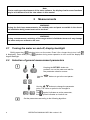
2.2
button during meter operation to turn on/off the display and
Selection of general measurement parameters
Keeping the SET/SEL button depressed, turn on the meter and wait for
the parameter selection screen.
Use the
eter.
buttons to go to the next param-
Use the
buttons to change the parameter
value. The value or symbol to be changed is
flashing.
The
symbol indicates an active parameter,
the
- symbol indicates an inactive one.
Set the parameters according to the following algorithm:
6
OPERATING MANUAL MZC-304 version 1.09
Parameter
Voltage for
Supply
Mains calculating AutoSoftware
Change PIN source se- Buzzer
voltage IK: rated/
OFF
updating
lection
measured
?
Symbol(s)
Press ENTER to validate the changes and go to the
measurement function,
or
...press ESC to go the measurement function without validating the changes.
Note:
- Before the first measurements, select the mains rated voltage Un (220/380V, 230/400V or 240/415V)
used in in the area where measurements are performed. This voltage value is used for calculating the
values of prospective short-circuit current, if this option was chosen from the main menu.
- The
symbol means that no auto-off time has been set.
- PIN settings - see section 3.5.2 Data Transmission.
- Use OR-1 receiver (section 3.5.1) to update the software. New software may be downloaded from
www.sonel.pl.
2.3
Remembering the last measurement result
Result of the latest measurement is remembered by the meter until a next measurement is started, or measurement settings are changed, or the measuring function is changed by means of the rotary switch, or the meter is switched off. When you go to the output screen of a given function with the
ESC button, you can recall this result by pressing ENTER. Similarly, you can view the latest measurement result after turning off and then turning on the meter.
2.4
Measurement of alternating voltage
The meter measures and displays alternating mains voltage in all measuring functions except
R. This voltage is measured for the frequencies within the range of 45..65 Hz. The test leads should
be connected as for a given measuring function.
OPERATING MANUAL MZC-304 version 1.09
7
2.5
Measurement of voltage and frequency
Set the rotary switch in the U,f
position.
Read the result of
measurement: the
voltage on the secondary display field, the
frequency on the
principal.
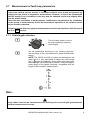
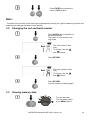
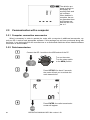
2.6
Checking correctness of PE (protective earth) connections
PE
or
When the meter is connected as in the the drawing, touch the contact electrode with your finger
and wait for about 1 second. When voltage if found on PE, the meter displays the symbol (error in the installation; PE connected to the phase
conductor) and generates a continuous audio signal. This option is available for the ZL-PE measurements.
Note:
WARNING:
When a dangerous voltage is detected on PE conductor, measurements must be immediately stopped and a fault in the installation must be removed.
- The person making a measurement must ensure that he/she is standing on a non-insulated floor during the measurement; otherwise the result of the measurement may be incorrect.
- The threshold value, which triggers the signal of exceeded allowable voltage on PE conduit, is approximately 50 V.
8
OPERATING MANUAL MZC-304 version 1.09
2.7
Measurement of fault loop parameters
If there are residual current devices in the tested network, they should be bypassed by
bridging for the period of impedance measurement. However, it should be remembered
that the tested circuit is modified in this way and the obtained results may slightly differ
from the actual results.
Each time after completion of measurements, modifications introduced to the installation
for the period of measurements should be removed and operation of the residual current
device should be checked.
The above remark does not apply to measurements of fault loop impedance with the use of
the ZL-PE RCD function
2.7.1 Cable length selection
Turn the rotary switch to one of
the loop impedance measurement ranges.
Set the parameters according to the following algorithm,
and according to the rules described in general parameters
setting.
NOTE: The WS-05 and WS-01 cables are detected by the
meter and it is then impossible to select the cable length
(the
symbol is displayed). Using cables terminated with
banana plugs, before starting to measure, select the appropriate length of the phase conductor, compatible with the
length of cable used for measurement.
Note:
Using cables from known manufacturers and selecting the correct length guarantees the
declared measurement accuracy.
OPERATING MANUAL MZC-304 version 1.09
9
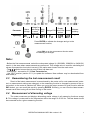
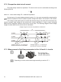
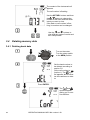
2.7.2 Prospective short-circuit current
The meter always measures impedance. The short-circuit current is calculated according to the
following formula:
Ik
Un
ZS
where: Un - mains rated voltage, ZS - measured impedance.
On the basis of Un rated voltage selected (section 2.1), the meter automatically recognizes the
measurement at phase-to-neutral or phase-to-phase voltage and takes it into account in the calculations.
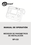
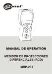
If the voltage of the tested mains is outside the tolerance range, the meter will not be able to determine a proper rated voltage for the short-circuit current calculation. In such a case, horizontal
dashes will be displayed instead a short-circuit current value. The following diagram shows voltage
ranges for which short-circuit current value is calculated.
Voltage range for which the impedance is measured
Un=220V
Un=230V
Un=240V
220
198
207
242
230
253
216 240
Voltage ranges UL-N, for which the
short-circuit current is calculated
264
418 440 U [V]
380
342
360
373
440
U [V]
415 440
U [V]
400
Voltage ranges UL.-L, for which the
short-circuit current is calculated
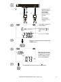
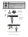
2.7.3 Measurement of fault loop parameters in the L-N and L-L circuits
Turn on the meter.
Turn the rotary switch
to the ZL-L ZL-N position.
Depending on needs, select cable length according to section 2.7.1.
10
OPERATING MANUAL MZC-304 version 1.09
a)
N L
or
b)
Connect test leads according to
the drawing
a) for measurement in the LN circuit
or
b) for measurement in the LL circuit
N L
The meter is ready for
measurement.
Phase conductor length or the
symbol.
UL-N or UL-L voltage
Make the measurement by pressing the
START button.
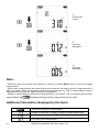
Read the main measurement result: fault loop
impedance ZS and the
mains voltage at the time of measurement.
To read additional results, press the
OPERATING MANUAL MZC-304 version 1.09
button.
11
IK
short-circuit
current
R
fault loop
resistance
XL
fault loop
reactance
Note:
- Enter the result into memory (see sections 3.1 and 3.2) or press ESCto return to go to the voltage
measurement.
- When many measurements are made at short time intervals, the meter may emit a large amount of
heat. As a result of this, the enclosure of the device may become hot. This is normal and the meter is
equipped with the protection against excessive temperature.
- Minimum interval between successive measurements is 5 seconds. This is controlled by the meter
which displays the
message informing that the measurement can be made.
Additional information displayed by the meter
The meter is ready for measurement.
Voltage on terminals L and N is outside the measurable range.
Voltage on terminals L and PE is outside the measurable range.
Error during the measurement.
12
OPERATING MANUAL MZC-304 version 1.09
Error during the measurement – voltage dip after the measurement.
Short circuit malfunction.
Conductor N is not connected.
Huge noise in the system during the measurement. The measurement result may be affected by a large, unspecified error.
The temperature inside the meter has risen above the limit. The
measurement is blocked.
The L and N conductors have been switched (voltage between
terminals PE and N).
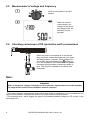
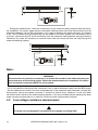
2.7.4 Measurement of fault loop parameters in the L-PE circuit
Turn on the meter.
Turn the rotary switch
to the ZL-PE position.
Depending on needs, select cable length according to section 2.7.1.
Connect the test
leads according
to one of the
drawings.
or
N PE
L
PE
a)
L
b)
0
Checking effectiveness of protection against electric shock
of the enclosure in case of: a) TN b) TT.
OPERATING MANUAL MZC-304 version 1.09
13
The meter is ready
for measurement.
Phase conductor length or the
symbol.
UL-PE voltage
Make measurement by pressing the START button.
Remaining issues connected with the measurements are the same as those described for measurements in L-N circuit or L-L circuit.
Note:
Double lead measurement is possible when a test lead other that the lead with a mains socket is selected.
Additional information displayed by the meter
Error messages and information - as for the L-N and L-L measurement.
2.7.5 Measurement of short circuit loop impedance in L-PE circuit protected
by a residual current device (RCD)
The MZC-304 enables the fault loop impedance measurements without altering the mains protected by RCD's with the rated current of at least 30mA.
Turn on the meter.
Turn the rotary switch
to the ZL-PE RCD position
Depending on needs, select the measurement parameters according
to section 2.7.1.
Connect the test leads according to one of the drawings.
14
OPERATING MANUAL MZC-304 version 1.09
Remaining issues connected with the measurements are the same as those described for measurements of the L-PE circuit.
Note:
- Maximum measurement time is about 32 seconds. The measurement can be interrupted by
pressing the ESC button.
In the electrical installations with 30 mA RCD's the sum of leakage currents of the installation and the
test current may trip the RCD. If this happens, try to reduce the leakage current in the tested mains
(for example by disconnecting loads).
Additional information displayed by the meter
Error messages and information - as for the L-N and L-L measurement.
2.8
Measurement of resistance to earth
The MPI-502 meter can be used for approximate measurements of resistance to earth. For this
purpose, the phase conductor is used as a secondary source of voltage which generates test current.
Connection diagram for the instrument for such measurement in the TN-C, TN-S and TT systems is
shown in the figure below.
OPERATING MANUAL MZC-304 version 1.09
15
N(PEN)
Rr
L
Ru
PE
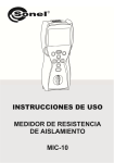
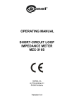
During the measurement, check the connections of the measured earth electrode with the electrical installation. For correct measurement, the tested earthing systm should be disconnected from the
electrical installation (N and PE conductors). If you want to measure the earth electrode, for instance
in the TN-C-S system and simultaneously use the phase of the same system as a secondary source
of current, disconnect the PE and N conductors from the measured earth electrode (see figure below).
Otherwise, the meter will measure an incorrect value (the test current will flow not only through the
measured earthing system).
L1
L2
L3
N
PE
Rr
Disconnect
L
PE
Ru
Note:
WARNING:
Disconnection of protective conductors is a serous life hazard for the staff performing the
measurements and also third parties. When the measurements are completed, the protective and neutral conductors MUST be reconnected.
- If it is not possible to disconnect the conductors, use an earth resistance meter from the MRU range.
- As the measurement result is the sum of impedances of the measured earth electrode, working earthing system, source and phase conductor, it contains a positive error. However, if such error does
not exceed a limit value for the tested earthing system, it can be concluded that the earthing has been
made correctly and and there is no need for a more accurate measurement methods.
2.9
Low-voltage resistance measurement
The meter can be damaged if connected to the voltage exceeding 500V.
16
OPERATING MANUAL MZC-304 version 1.09
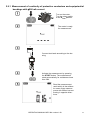
2.9.1 Measurement of continuity of protective conductors and equipotential
bondings with 200 mA current
Turn on the meter.
Turn the rotary switch
to the RCONT position.
The meter is ready
for measurement.
RX
N
L
Connect test leads according to the drawing.
Activate the measurement by pressing
the START button. The measurement
starts automatically for resistances lower
than 30
Read the measurement
result which is the arithmetic mean of two measurements with 200mA current
flowing in opposite directions.
OPERATING MANUAL MZC-304 version 1.09
17
Additional information displayed by the meter
The tested facility is live. The measurement is blocked.
Immediately disconnect the meter from the facility
(both conductors)!
Huge noise in the system during the measurement. The
measurement result may be affected by a large, unspecified error.
Measuring range is exceeded.
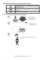
2.9.2 Low-current measurement of resistance
Turn on the meter.
Turn the rotary switch
to the Rx position.
The meter is ready
for measurement.
RX
N
18
L
Connect test leads according to the drawing.
OPERATING MANUAL MZC-304 version 1.09
Read the measurement
result.
Additional information displayed by the meter
The tested facility is live. The measurement is blocked.
Immediately disconnect the meter from the facility
(both conductors)!
Huge noise in the system during the measurement. The
measurement result may be affected by a large, unspecified error.
Measuring range is exceeded.
2.9.3 Compensation of test leads resistance - autozeroing
Turn on the meter.
Turn the rotary switch
to the RCONT or Rx position
Set the autozeroing according to the following algorithm.
Short the test leads.
N
L
Activate the autozeriong by pressing the
START button.
OPERATING MANUAL MZC-304 version 1.09
19
After completion of autozeroing, the meter automatically switches to the
"ready for measurement"
mode.
Note:
- The
message remains on the display after switching into one of the measurement functions (resistance or continuity measurement) indicating that the measurement is made with compensated least leads resistance.
- To remove the compensation, perform the above-mentioned activities but with open test leads.
When you enter the measurement screen, the
message will not be displayed.
Additional information displayed by the meter
The tested facility is live. The measurement is blocked.
Immediately disconnect the meter from the facility
(both conductors)!
20
OPERATING MANUAL MZC-304 version 1.09
3
Memory of measurement result data
MZC-304 meters are equipped with the memory that can store 10000 single measurement results. The whole memory is divided into 10 memory banks, each of them containing 99 memory cells.
Thanks to dynamic memory allocation, each of the memory cells can contain different quantity of single measurement results, depending on the needs. Optimal use of the memory can be ensured in this
way. Each measurement result can be stored in a memory cell marked with a selected number and in
a selected memory bank. Thanks to this, the user of the meter can, at his/her discretion, assign memory cell numbers to individual measurement points and the memory bank numbers to individual facilities. The user can also perform measurements in any sequence and repeat them without losing
other data.
Memory of measurement result data is not deleted when the meter is switched off. Thanks to
this, the data can be later read or sent to a computer. The number of a current memory cell or memory bank is not changed either.
Note:
- Results of measurements performed for all measuring functions can be stored in one memory cell.
- After each entry of the measurement result to the cell, its number is automatically incremented. Set
the appropriate cell number to allow entering to a single cell of successive measurement results relating to a given measuring point (facility).
- Only the results of measurements activated by pressing the START button can be stored in the
memory (except autozeroing in low-voltage resistance measurement).
- It is recommended to delete the memory after reading the data or before performing a new series of
measurements that may be stored in the same memory cells as the previous ones.
3.1
Storing the measurement result data in the memory
Press ENTER after completion of
the measurement.
The meter is in the memory storing mode.
Cell is empty.
The cell contains the
result of the same type
which is to be entered.
OPERATING MANUAL MZC-304 version 1.09
21
The cell contains the
measurement results of
the displayed types.
The cell contains the
measurement results of
all types.
Use
the
buttons to view
different types of results and their
components.
Select the bank and cell number (see section
3.2) or leave the current number. Then press
ENTER again. The following screen
appears for a moment, accompanied by three
short beeps, and then the meter returns to display the last measurement result.
An attempt to overwrite causes
the warning symbol to appear.
22
OPERATING MANUAL MZC-304 version 1.09
Press ENTER to overwrite the
result or ESC to abort.
Note:
- Complete set of results (main result and supplementary results) for a given measuring function and
measurement settings are stored in the memory.
3.2
Changing the cell and bank number
Press ENTER after completion of
the measurement.
The meter is in the memory storing mode.
The cell number is flashing.
To change, use the
and
buttons.
Press SET/SEL.
The bank number is flashing.
To change, use the
and
buttons.
Press SET/SEL.
The cell number is flashing again.
3.3
Viewing memory data
Turn on the meter.
Turn the rotary switch
to the MEM position.
OPERATING MANUAL MZC-304 version 1.09
23
The content of the last saved cell
appears.
The cell number is flashing.
Use the SET/SEL buttons and then
the
buttons to change the
number of the bank and cell which
intent you want to view.
If the bank or cell number is flashing, its number can be changed.
Use the
and
buttons to
view different types of results and
their components.
3.4
Deleting memory data
3.4.1 Deleting bank data
Turn on the meter.
Turn the rotary switch
to the MEM position.
Set the bank number to
be deleted according to
section 3.2.
St the cell number to
(before 1). The
symbol appears which indicates the readiness to delete.
Press ENTER .
The
and
symbols appear,
asking you to confirm deletion.
24
OPERATING MANUAL MZC-304 version 1.09
Press ENTER to start deleting or ESC
to abort.
The deletion progress is shown on
the display as scrolling cell numbers.
When deletion is
complete, the meter
generates three
short beeps and
sets the cell number
to 1.
3.4.2 Deleting the whole memory
Turn on the meter.
Turn the rotary switch
to the MEM position.
Set the bank number to
(before 0). The symbol
appears which indicates the readiness to delete.
Press ENTER.
The
and
symbols appear,
asking you to confirm deletion.
Press ENTER to start deleting or ESC
to abort.
OPERATING MANUAL MZC-304 version 1.09
25
The deletion progress is shown on
the display as
scrolling bank and
cell numbers.
When deletion is
complete, the meter generates three
short beeps and
sets the cell number to 1.
3.5
Communication with a computer
3.5.1 Computer connection accessories
What is necessary in order to operate the meter with a computer is additional accessories, namely an OR-1 receiver and appropriate software. If this package has not been purchased along with
the meter, it can be bought from the manufacturer or an authorized distributor where detailed software
information is also available.
3.5.2 Data transmission
Connect the OR-1 module to the USB socket of the PC.
Turn on the meter.
Turn the rotary switch
to the MEM position.
Press SET/SEL for about 2 seconds;
the meter will ask you to activate the
radio transmission.
Press ENTER, the radio transmission
screen will appear.
26
OPERATING MANUAL MZC-304 version 1.09
To transmit data, follow the instructions of the software.
Press ESC to exit the transmission mode.
Note:
Standard pin for OR-1 is the „123”. Settings in the meter according to section 2.2.
OPERATING MANUAL MZC-304 version 1.09
27
4
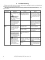
Troubleshooting
Before returning the instrument for repair, call the service, perhaps the meter is not damaged and
the problem has occurred for another reason.
The meter repairs should be carried out only in the outlets authorized by the manufacturer.
The following table describes the recommended procedure in certain situations that occur when
using the meter.
Measuring
function
All
Fault
loop
Symptom
The meter will not start
after pressing the
button.
The
symbol is displayed during the voltage measurement.
Meter turns off during
the initial test.
Measurement errors
after moving the meter
from cold environment
to warm and humid
environment.
Sucessive results obtained in the same measuring point are significantly different from
each other
The meter indicates the
values close to zero or
zero irrespective of the
location of the measurement and these values are significantly different than expected.
The symbol does not
appear, although the
voltage between the
contact electrode and
the PE conductor exceeds the detector
threshold (about 50V)
28
Cause
Discharged or incorrectly placed batteries/
rechargeable batteries
Action
Check if the batteris are
placed correctly, replace
and/or recharge the batteries. If this does not help,
sent the meter for servicing.
No acclimatization
Do not perform the measurements until the meter
reaches the ambient temperature (about 30 minutes) and dries.
Incorrect connections in Check the connections
the tested mains.
and remove defects
Mains with high noise or Perform a larger number
unstable voltage
of measurements, average the results
Incorrectly selected test
leads in the meter settings.
Contact electrode is not
functioning correctly or
the meter input circuits
are damaged
Rotary switch in a wrong
position.
Return the meter for servicing; he use of a malfunctioning meter isunacceptable
Contact electrode is active
for the measurements of
the ZL-PE fault loop parameters.
OPERATING MANUAL MZC-304 version 1.09
5
5.1
Power supply of the meter
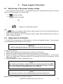
Monitoring of the power supply voltage
The charge level of the batteries or rechargeable batteries is indicated by the symbol in the right
upper corner of the display on a current basis:
Batteries charged
Batteries discharged
Replace or recharge the batteries!
Note:
The
symbol in the display means that the supply voltage is too low and indicates that the batteries must be replaced or recharged,
Measurements performed with an insufficient supply voltage feature additional errors which the
user is unable to evaluate.
5.2
Replacement of batteries
The MZC-304 is powered by four LR6 batteries or AA size rechargeable batteries. They are placed
in the compartment at the bottom of the enclosure.
WARNING:
Before replacing the batteries, disconnect the test leads from the meter.
To replace the batteries:
1. Disconnect the leads from the measuring circuit and turn off the meter;
2. Remove the screw that secures the battery cover (the bottom of the enclosure);
3. Replace all batteries. Observe the correct polarity when putting new batteries ("-" on the elastic
part of the contact plate). Reversed polarity will not damage the meter or the batteries, but the
meter will not work;
4. Place and tighten the battery compartment cover.
NOTE!
After replacing the batteries, always set the power supply type in the main MENU.
The correct charge indication depends on this setting (the discharge characteristics of disposable and rechargeable batteries are different).
NOTE!
Have the meter serviced in case of battery leakage inside the compartment.
Batteries must be recharged in an external charger.
OPERATING MANUAL MZC-304 version 1.09
29
5.3
General rules of using the Nickel Metal Hydride (Ni-MH) batteries
- If you are not going to use the instrument for a longer time, remove the rechargeable batteries and
store them separately.
- Store the rechargeable batteries in a dry, cool and well ventilated place and protect them from direct
sunlight. The long storage temperature should be below 30 degrees C. If the batteries are stored long
at high temperatures, the chemical processes may reduce their life.
- The NiMH rechargeable batteries usually withstand 500-1000 charging cycles. Such batteries
achieve full capacity after forming (2-3 discharging and charging cycles). The most important factor
which influences the battery life is the discharge level. The deeper the discharge level, the shorter the
battery life.
- The memory effect appears in the NiMH batteries in a limited scope. These batteries can be recharged without more serious consequences. It is, however, recommended to discharge them completely every few cycles.
- During the storage of the Ni-MH rechargeable batteries, they are subject to self-discharge process at
the rate of about 30% a month. Keeping the batteries at high temperatures may accelerate this process even two times. In order not to allow an excessive discharging of the batteries (after which the
forming will be needed), recharge the batteries once in a while (even unused batteries).
- Modern, fast chargers detect too low and too high temperature of the batteries and respond accordingly. If the temperature is too low, the charging process should not start as it might irrevocably damage a rechargeable battery. The battery temperature increase is a signal to stop the charging and is
typical. In addition to faster temperature increase of a battery which will not be fully charged, charging
at high ambient temperatures results, however, in a reduced life.
- Remember that with fast charging, the batteries are charged to about 80% of their capacity; better
results can be achieved by continuing the charging process: the charger then goes into the small current charging mode and after a few hours the batteries are fully charged.
- Do not charge and do not use the batteries at extreme temperatures as they reduce the life of batteries. Avoid using the battery-powered devices in very hot places. The rated operating temperature
must be observed at all times.
30
OPERATING MANUAL MZC-304 version 1.09
6
Cleaning and maintenance
NOTE!
Use only the maintenance methods presented by the manufacturer in this
manual.
Clean the meter casing and the case with a wet cloth, using generally available detergents. Do
not use any solvents and cleaning media which could scratch the casing (powder, paste, etc.).
The probes can be cleaned with water and then wiped dry. Before longer storage, it is recommended to lubricate the probes with any machine grease.
Clean the spools and leads with water and detergents, then wipe dry.
The meter electronic system is maintenance free.
7
Storage
When storing the instrument, observe the following recommendations:
disconnect all leads from the meter,
thoroughly clean the meter and all accessories,
wind long test leads onto the spools,
if you are not going to use the instrument for a longer time, remove the batteries,
during a prolonged storage recharge the batteries from time to time to prevent total discharging.
8
Dismantling and disposal
Used electric and electronic equipment should be collected selectively, i.e. not placed with other
types of waste.
Used electronic equipment shall be sent to the collection point according to the Used Electric and
Electronic Equipment Act.
Before sending the instrument to the collection point, do not dismantle any parts by yourself.
Observe local regulations on disposal of packagings and used batteries.
OPERATING MANUAL MZC-304 version 1.09
31
9
9.1
Technical specifications
Basic data
Abbreviation "m.v" used in the specification of measurement uncertainty means a standard measured value.
Voltage measurement
Range
0.0...299.9V
300...500V
Frequency range: 45...65Hz
Resolution
0,1V
1V
Measurement uncertainty
(2% m.v. + 6 digits)
(2% m.v. + 2 digits)
Resolution
0,1Hz
Measurement uncertainty
(0.1% m.v. + 1 digit)
Frequency measurement
Range
45.0...65.0Hz
Voltage range: 50 .. 500V
Measurement of fault loop impedance ZL-PE, ZL-N, ZL-L
Measurement of fault loop impedance ZS
Test range according to IEC 61557:
Test lead
1,2m
5m
10m
20m
WS-01, -05
Measurement range ZS
0.13...1999
0.17...1999
0.21...1999
0.29...1999
0.19...1999
Display range:
Display range
Resolution
Measurement uncertainty
0.00...19.99
0,01
(5% m.v. + 3 digits)
20.0...199.9
0,1
(5% m.v. + 3 digits)
200...1999
1
(5% m.v. + 3 digits)
Rated operating voltage UnL-N/ UnL-L: 220/380V, 230/400V, 240/415V
Operating voltage range: 180…270V (for ZL-PE i ZL-N) and 180…460V (for ZL-L)
Rated mains frequency fn: 50Hz, 60Hz
Operating frequency range: 45…65Hz
Maximum test current: 7.6 A for 230 (3x10ms), 13.3 A for 400V (3x10ms)
Control of correctness of PE terminal connection by means of a contact electrode (applicable to
ZL-PE)
Fault loop resistance RS and fault loop reactance XS
Display range
Resolution
0.00..19.99
0.01
20.0..199.9
0.1
Calculated and displayed for ZS<20
32
Measurement uncertainty
(5% + 5 digits) of ZS value
(5% + 5 digits) of ZS value
OPERATING MANUAL MZC-304 version 1.09
Short-circuit current IK
Test range according to IEC 61557 can be calculated on the basis of test ranges Z S and rated voltages.
Display range
Resolution
Measurement uncertainty
0.110…1.999A
0.001 A
2.00...19.99A
0.01 A
20.0...199.9A
0.1 A
Calculated on the basis of
uncertainty for fault loop
200...1999A
1A
2.00...19.99kA
0.01 kA
20.0…40.0kA
0.1 kA
Prospective fault current calculated and displayed by the meter may slightly differ from the value calculated by the user with a calculator, basing on the displayed value of the impedance,
because the meter calculates the current from unrounded value of fault loop impedance (which
is used for displaying). As the correct value, consider I k current value, displayed by the meter or
by firmware.
Measurement of fault loop impedance ZL-PE RCD (without RCD tripping)
Measurement of fault loop impedance ZS
Measuring range acc. to IEC 61557: 0,5…1999 for 1.2m leads, WS01 i WS05 and 0.51...1999 for
5m, 10m and 20m leads
Display range
Resolution
Measurement uncertainty
0.00...19.99
0,01
(6% m.v. + 10 digits)
20.0...199.9
0,1
(6% m.v. + 5 digits)
200...1999
1
(6% m.v. + 5 digits)
It will not trip RCD's of IΔn ≥ 30 mA
Rated operating voltage Un: 220V, 230V, 240V
Operating voltage range: 180…270V
Rated mains frequency fn: 50Hz, 60Hz
Operating frequency range: 45…65Hz
Control of correctness of PE terminal connection by means of a contact electrode
Fault loop resistance RS and fault loop reactance XS
Display range
Resolution
0.00..19.99
0.01
20.0..199.9
0.1
Calculated and displayed for ZS<20
Measurement uncertainty
(6% + 10 digits) of ZS value
(6% + 5 digits) of ZS value
Short-circuit current IK
Test range according to IEC 61557 can be calculated on the basis of test ranges Z S and rated voltages.
Display range
Resolution
Measurement uncertainty
0.110…1.999A
0.001 A
2.00...19.99A
0.01 A
20.0...199.9A
0.1 A
Calculated on the basis of
uncertainty for fault loop
200...1999A
1A
2.00...19.99kA
0.01 kA
20.0…24.0kA
0.1 kA
Prospective fault current calculated and displayed by the meter may slightly differ from the value calculated by the user with a calculator, basing on the displayed value of the impedance,
because the meter calculates the current from unrounded value of fault loop impedance (which
is used for displaying). As the correct value, consider I k current value, displayed by the meter or
by firmware.
OPERATING MANUAL MZC-304 version 1.09
33
Low-voltage continuity and resistance measurement
Measurement of continuity of protective conductors and equipotential bondings with 200 mA
current
Measurement range according to IEC 61557-4:
Range
Resolution
Measurement uncertainty
0.00...19.99
0.01
20.0...199.9
0.1
(2% m.v. + 3 digits)
200...400
1
Voltage at open terminals: 4…9V
Output current at R<2: min 200mA (ISC: 200...250mA)
Compensation of test leads resistance
Measurements for both current polarizations
Low-current resistance measurement
Range
Resolution
0.0...199.9
0.1
200...1999
1
Voltage at open terminals: 4…9V
Short-circuit current ISC: 8…15mA
Audio signal for measured resistance < 30 ± 50%
Compensation of test leads resistance
Measurement uncertainty
(3% m.v. + 3 digits)
Other technical specification
a)
b)
c)
d)
e)
f)
g)
h)
i)
j)
k)
l)
m)
n)
o)
p)
q)
r)
s)
t)
type of insulation ..................................................... double, EN 61010-1 and IEC 61557 compliant
measurement category ................................................... IV 300V (III 600V), EN 61010-1 compliant
degree of protection of enclosure acc. to EN 60529 ................................................................. IP67
meter power supply .............LR6 alkaline batteries or NiMH rechargeable batteries size AA (4 pcs)
dimensions .............................................................................................................. 220x98x58 mm
meter weigth .................................................................................................................... about 1 kg
storage temperature ..................................................................................................... –20...+70C
operating temperature ...................................................................................................... 0...+50C
humidity ............................................................................................................................. 20...80%
reference temperature ..................................................................................................... +23 ± 2C
reference humidity ............................................................................................................. 40...60%
altitude (above sea level) ................................................................................................... <2000 m
time to Auto-OFF ......................................................................................................... 120 seconds
number of measurements Z (for rechargeable batteries) ........ >5000 (2 measurements per minute)
display ........................................................................................................................LCD segment
memory of measurement results ................................................................ 990 cells, 10000 entries
data transmission ...................................................................... radio link, waveband ISM 433 MHz
quality standard .......................... development, design and manufacturing are ISO 9001 compliant
the device meets the requirements of the IEC 61557 standard
the product meets the EMC requirements (immunity for industrial environment) according to the
following standards ........................................................ EN 61326-1:2006 and EN 61326-2-2:2006
9.2
Additional information
Information about additional uncertainty is useful mainly when the meter is used in untypical conditions and for the measurements laboratories during calibration.
34
OPERATING MANUAL MZC-304 version 1.09
9.2.1
Additional uncertainty according to IEC 61557-3 (Z)
Influencing value
Location
Supply voltage
Temperature 0...35°C
Phase angle 0..30° at the bottom of measurement range
Frequency 99%..101%
Mains voltage 85%..110%
Harmonics
DC component
9.2.2
Designation
E1
E2
E3
Additional uncertainty
0%
0% (BAT is not displayed)
1.2m lead – 0Ω
5m lead – 0.011Ω
10m lead – 0.019Ω
20m lead – 0.035Ω
WS-01, WS-05 leads – 0.015Ω
E6.2
0,6%
E7
E8
E9
E10
0%
0%
0%
0%
Additional uncertainty according to IEC 61557-4 (R ±200mA)
Influencing value
Location
Supply voltage
Temperature 0...35°C
Designation
E1
E2
E3
Additional uncertainty
0%
0,5% (BAT is not displayed)
1,5%
OPERATING MANUAL MZC-304 version 1.09
35
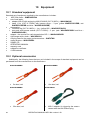
10 Equipment
10.1 Standard equipment
Standard set of equipment supplied by the manufacturer includes:
MZC-304 meter – WMPLMZC304
set of test leads:
adapter WS-05 with angle plug UNI-SCHUKO (CAT III 300V) – WAADAWS05
leads 1,2m (CAT III 1000V) with banana plugs – 3 pcs (yellow WAPRZ1X2YEBB, redWAPRZ1X2REBB and blue - WAPRZ1X2BUBB)
accessories
crocodile clip (CAT III 1000V) – 1 pc. (yellow K02 – WAKROYE20K02)
test prod with banana socket (CAT II 1000V) – 2 pcs. (rad– WASONREOGB1 and blue –
WASONBUOGB1)
adapter - the receiver for radio transmission OR-1 – WAADAUSBOR1
rigid hanger with a hook – WAPOZUCH1
carrying case for the meter and accessories – WAFUTM6
meter harness – WAPOZSZE4
SONEL CD
OPERATING MANUAL
warranty card
calibration certificate
4 LR6 batteries
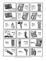
10.2 Optional accessories
Additionally, the following items that are not included in the scope of standard equipment can be
purchased from the manufacturer or the distributors:
36
WAPRZ005REBB
WAPRZ010REBB
5m lead, red
10m lead, red
WAPRZ020REBB
WAADAWS01
20m lead, red
WS-01 adapter for triggering the measurement with the UNI-Schuko plug
OPERATING MANUAL MZC-304 version 1.09
WASONYEOGB1
WAKRORE20K02
test prod with banana socket
WAADAAGT16P - five-wire version
WAADAAGT16C - four-wire version
crocodile, red
WAADAAGT32P - five-wire version
WAADAAGT32C - four-wire version
AGT-16P adapter for three-phase sockets
WAADAAGT63P - five-wire version
AGT-32P adapter for three-phase sockets
WAPROSONPE4
AGT-63P adapter for three-phase sockets
WAPROSCHEM
SONEL Electrical Measurements software for measurement reports
WAPROKALK
SONEL Schematic software for creating
drawings, electrical installation diagrams
SONEL Calculations software for measurement calculations
OPERATING MANUAL MZC-304 version 1.09
37
WAADAKEY1
LSWPLMZC304
calibration certificate
adapter – USB dongle for the software
Note
The software is supported by the following systems: Windows XP (Service
Pack 2), Windows Vista, Windows 7.
11 Manufacturer
The manufacturer of the device and provider of warranty and post-warranty service:
SONEL S.A.
ul. Wokulskiego 11
58-100 Świdnica
Poland
tel. +48 74 858 38 60
fax +48 74 858 38 09
E-mail: [email protected]
Web page: www.sonel.pl
NOTE
Service repairs must be performed solely by the manufacturer.
38
OPERATING MANUAL MZC-304 version 1.09
OPERATING MANUAL MZC-304 version 1.09
39
NOTES
40
OPERATING MANUAL MZC-304 version 1.09