1
INDEX
CE DECLARATION OF CONFORMITY FOR MACHINES.................................................................................................. 2
WARNINGS FOR THE INSTALLER.................................................................................................................................. 2
1. DESCRIPTION AND TECHNICAL SPECIFICATIONS.................................................................................................... 3
1.1 MAXIMUM USE CURVE.............................................................................................................................................. 4
2 ELECTRIC PREPARATIONS (standard system)........................................................................................................... 4
3 DIMENSIONS .......................................................................................................................................................... 4
ENGLISH
3.1 BARRIER 620................................................................................................................................................... 4
3.2 BARRIER 640 - 642.......................................................................................................................................... 4
4 INSTALLING THE AUTOMATED SYSTEM . ................................................................................................................... 4
4.1 PRELIMINARY CHECKS.............................................................................................................................................. 4
4.2 MASONRY FOR FOUNDATION PLINTH........................................................................................................................ 4
4.3 MECHANICAL INSTALLATION . .................................................................................................................................. 5
4.3.1 BARRIER 620.................................................................................................................................................... 5
4.3.2 BARRIER 640 - 642........................................................................................................................................... 6
4.4 ADJUSTING THE BALANCING SPRING........................................................................................................................ 6
5 START-UP.................................................................................................................................................................. 6
5.1 CONNECTION TO CONTROL BOARD . ...................................................................................................................... 6
5.2 ADJUSTING THE TRANSMITTED TORQUE..................................................................................................................... 6
5.3 ADJUSTING THE TRAVEL LIMIT SLOW DOWN.............................................................................................................. 6
5.4 AUTOMATED SYSTEM TEST......................................................................................................................................... 7
6 MANUAL MODE OPERATION ................................................................................................................................... 7
7 RESTORING NORMAL OPERATION MODE................................................................................................................. 7
8 MAINTENANCE ....................................................................................................................................................... 7
8.1 TOPPING UP OIL....................................................................................................................................................... 7
8.2 BLEEDING OPERATION.............................................................................................................................................. 7
9 REPAIRS.................................................................................................................................................................. 8
10 CHANGING THE RH (LH) VERSION OF THE BARRIER INTO THE LH (RH) VERSION....................................................... 8
11 AVAILABLE ACCESSORIES ..................................................................................................................................... 8
12 DETAILED TECHNICAL SPECIFICATIONS.................................................................................................................. 10
CE DECLARATION OF CONFORMITY FOR MACHINES
(DIRECTIVE 98/37/EC)
Manufacturer: FAAC S.p.A.
Address:
Via Benini, 1 - 40069 Zola Predosa BOLOGNA - ITALY
• is built to be integrated into a machine or to be assembled with other machinery to create a machine under
the provisions of Directive 98/37/EEC and subsequent amendments 91/368 EEC, 93/44 EEC and 93/68 EEC;
• conforms to the essential safety requirements of the other following EEC directives:
73/23/EEC and subsequent amendment 93/68/EEC.
89/336/EEC and subsequent amendment 92/31/EEC and 93/68/EEC
Furthermore, the manufacturer declares that the machinery must not be put into service until the machine into
which it will be integrated or of which it will become a component has been identified and its conformity to the
conditions of Directive 89/392/EEC and subsequent modifications assimilated in Italian National legislation under
Presidential Decree No. 459 of 24 July 1996 has been declared.
.
Bologna, 01 June 2007
The Managing Director
A. Bassi
WARNINGS FOR THE INSTALLER
GENERAL SAFETY OBLIGATIONS
1)
ATTENTION! To ensure the safety of people, it is important that you read
all the following instructions. Incorrect installation or incorrect use of the
product could cause serious harm to people.
14) Make sure that the earthing system is perfectly constructed, and connect
metal parts of the means of the closure to it.
15) The automated system is supplied with an intrinsic anti-crushing safety
device consisting of a torque control. Nevertheless, its tripping threshold
must be checked as specified in the Standards indicated at point 10.
2) Carefully read the instructions before beginning to install the product.
3) Do not leave packing materials (plastic, polystyrene, etc.) within reach
of children as such materials are potential sources of danger.
16) The safety devices (EN 12978 standard) protect any danger areas
against mechanical movement Risks, such as crushing, dragging, and
shearing.
4) Store these instructions for future reference.
5) This product was designed and built strictly for the use indicated in this
documentation. Any other use, not expressly indicated here, could
compromise the good condition/operation of the product and/or be
a source of danger.
17) Use of at least one indicator-light (e.g. FAACLIGHT) is recommended
for every system, as well as a warning sign adequately secured to the
frame structure, in addition to the devices mentioned at point “16”.
18) FAAC declines all liability as concerns safety and efficient operation of
the automated system, if system components not produced by FAAC
are used.
6) FAAC declines all liability caused by improper use or use other than that
for which the automated system was intended.
7) Do not install the equipment in an explosive atmosphere: the presence
of inflammable gas or fumes is a serious danger to safety.
19) For maintenance, strictly use original parts by FAAC.
20) Do not in any way modify the components of the automated
system.
8) The mechanical parts must conform to the provisions of Standards
EN 12604 and EN 12605.
21) The installer shall supply all information concerning manual operation
of the system in case of an emergency, and shall hand over to the user
the warnings handbook supplied with the product.
For non-EU countries, to obtain an adequate level of safety, the
Standards mentioned above must be observed, in addition to national
legal regulations.
22) Do not allow children or adults to stay near the product while it is
operating.
9) FAAC is not responsible for failure to observe Good Technique in
the construction of the closing elements to be motorised, or for any
deformation that may occur during use.
10) The installation must conform to Standards EN 12453 and EN 12445.
23) Keep radiocontrols or other pulse generators away from children, to
prevent the automated system from being activated involuntarily.
For non-EU countries, to obtain an adequate level of safety, the
Standards mentioned above must be observed, in addition to national
legal regulations.
24) Transit is permitted only when the automated system is idle.
25) The user must not attempt any kind of repair or direct action whatever
and contact qualified personnel only.
11) Before attempting any job on the system, cut out electrical power.
26) Maintenance: check at least every 6 months the efficiency of the
system, particularly the efficiency of the safety devices (including, where
foreseen, the operator thrust force) and of the release devices.
12) The mains power supply of the automated system must be fitted with
an all-pole switch with contact opening distance of 3mm or greater.
Use of a 6A thermal breaker with all-pole circuit break is
recommended.
27) Anything not expressly specified in these instructions is not permitted.
13) Make sure that a differential switch with threshold of 0.03 A is fitted
upstream of the system.
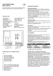
ENGLISH
Declares that: Barrier mod. 620, mod. 640, mod. 642,
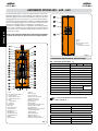
AUTOMATED SYSTEM 620 - 640 - 642
ENGLISH
The automated system consists of a white beam in aluminium,
with reflex reflectors and a steel upright. The operator is located
inside the upright, and consists of a hydraulic control unit and two
plunging pistons which, by means of a rocker, rotate the beam.
The beam stays balanced thanks to a balancing spring assembled
on one of the plunging pistons. The electronic control unit is also
housed in the upright, inside a waterproof compartment.
The system is supplied with an adjustable anti-crushing safety
device. It also includes a device stopping and locking the beam
in any position, and a handy manual release for use in case of
power cuts or faults.
The 620 - 640 - 642 automated systems were designed and built
to control vehicle access. Do not use for any other purpose.
37 Lock
38 Hatch
39 Protective grid for air intakes
40 Cooling fan
(sonly 620 rapid, 640 and 642)
Fig. 2
1. DESCRIPTION AND TECHNICAL SPECIFICATIONS
TAB. 1 Technical specifications (*) BARRIER MODEL
1 Beam
2 Travel limit mechanical stop device
3 Drive transmission unit
4 Adjustable travel limit cam RH
5 Adjustable travel limit cam LH
6 Rocker
7 LH travel limit device
8 Oil filling plug
9 Breather screw
10 Cooling fins
11 Piston bleed screw LH
12 Plunging piston LH
13 Hydraulic control unit
14 Feeder pipe LH
15 CLOSING by-pass screw
16 OPENING by-pass screw
17 Upright
18 Hole for cables LH
19 Tie rod
20 Foundation plate
21 Hole for cables RH
22 Earth connector securing screw
23 Cable routing sheath
24 Electronic control board
25 Feeder pipe RH
26 Manual release
27 Spring support position length: 460 mm
28 Protective grid for air intakes
29 Plunging piston RH
30 Spring support position length: 400 mm
31 Balancing spring support
32 Balancing spring
33 Piston bleed screw RH
34 Travel limit device RH
35 Balancing adjustment ring-nut
36 Travel limit mechanical stop device
620
640
642
Power supply (Vac / Hz)
230 {+6%/ -10%} / 50
Absorbed power (W)
220
Absorbed current (A)
1
Type of oil
FAAC HP OIL
Oil quantity (Lt)
~ 1.8
Winding heat protection (°C)
120
Anti-crushing system
standard by-pass valves
Type of slow-down
Electronic
Operating ambient temperature (°C)
-20 / +55
Hood protective treatment
Cataphoresis
Hood painting
Polyester RAL 2004
AISI 316 L
stainless steel
Protection class
IP44
Upright dimensions LxHxP (mm)
see Fig. 4 and 5
(*) For more details about the selected barrier model,
refer to chapter 12
TECHNICAL DETAILS OF 1400 rpm ELECTRIC MOTOR
Power supply (Vac{+6%/ -10%}/Hz)
230 / 50
Absorbed power (W)
200
Absorbed current (A)
1
TECHNICAL DETAILS OF 2800 rpm ELECTRIC MOTOR
Fig. 1
Power supply (Vac{+6%/ -10%}/Hz)
230 / 50
Absorbed power (W)
200
Absorbed current (A)
1
Notes:
1.1 MAXIMUM USE CURVE
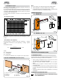
1) To lay cables, use adequate rigid and/or flexible tubes.
2) Always separate connection cables of low voltage
accessories from those operating at 230v~. To prevent any
interference whatever, use separate sheaths.
The curve makes it possible to establish maximum work time (T)
according to use frequency (F).
E.g.: Operators 620 rapid, 640, 642 R/40 and 642/70 can operate
non-stop at 100% use frequency as they are provided with a
cooling fan. Models 620 standard and 642 std/40 can operate
non-stop at 70% use frequency.
To ensure efficient operation, operate in the work range under
the curve.
3 BARRIER DIMENSIONS
3.1 BARRIER 620
Ø 85
-144
L
LP=
L
144
25
90
105,3
1080
Fig. 4
Dimensions are in mm.
3.2 BARRIERS 640 - 642
Important: The curve is obtained at a temperature of 24 °C.
Exposure to the direct sun rays can reduce use frequency down
to 20%
L
380
20
0
Ø 85
Calculation of use frequency
50
The percentage of effective work time (opening + closing)
compared to total time of cycle (opening + closing + pause
times).
Calculation formula:
Ta + Tc
X 100
Ta + Tc + Tp + Ti
Dimensions are in mm.
Fig. 5
4 INSTALLING THE AUTOMATED SYSTEM
4.1 PRELIMINARY CHECKS
To ensure safety and an efficiently operating automated system,
make sure the following conditions are observed:
2 ELECTRIC PREPARATIONS (standard system)
•
•
•
•
•
Barriers mod. 620 / 640 / 642
Photocells
Key push-button
Flashing light
390
0
where:
Ta = opening time
Tc = closing time
Tp = pause time
Ti = interval time between one complete cycle and another
b
c
d
850
100
1080
25
23
%F =
165
50
When moving, the beam must not, on any account, meet
any obstacles or overhead power cables.
The soil must permit sufficient stability for the foundation
plinth.
There must be no pipes or electrical cables in the plinth
excavation area.
if the barrier body is exposed to passing vehicles, install, if
possible, adequate means of protection against accidental
impact.
Check if an efficient earth socket is available for connecting
the upright.
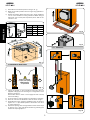
4.2 MASONRY FOR FOUNDATION PLINTH
e Radio receiver
f Magnetic loops
Fig. 3
WALL THE FOUNDATION PLATE TO ALLOW EASY ACCESS
TO THE BARRIER HATCH.
ENGLISH
Use frequency graph
1) Assemble the foundation plate as in fig.6. ref. a
2) Make a foundation plinth as shown in fig.4 ref.b (referred to
clayey soil)
3) Wall the foundation plinth as shown in fig.6, ref.b, supplying
one or more sheaths for routing electrical cables. Using a
spirit level, check if the plate is perfectly level. Wait for the
cement to set.
ENGLISH
A
DIMENSION
620
640-642
A
360
390
B
290
320
C
200
230
D
94
124
Fig. 8
m
C
D
5 mm
B
m
m
==
40
=
0
A
=
Fig. 9
4.3.1 BARRIER 620
500 mm
600 m
B
A
B
Fig. 6
4.3 MECHANICAL INSTALLATION
RH
When the barrier
is open, the spring
MUST NOT be
compressed
LH
Fig. 7
1) Fasten the upright on the foundation plate using the four
supplied nuts (fig.8) and checking the configuration of the
barrier as in figure 7.
Remember that the hatch of the upright should normally
face the building.
2) Set the operator for manual operation as described in chapter 6.
3) Remove and store the breather screws as shown in Fig.9.
4) Assemble the beam, using the supplied screws, as shown in
figures 10 or 11 (The rubber profile of the beam must face
in closing direction).
5) Adjust the opening and closing travel limit mechanical stops
as per fig.12 a. and verify beam balancing following the
instructions in paragraph 4.4.
D
C
Fig. 10
For the electrical connections, refer to the dedicated
instructions of the control board.
4.3.1 BARRIER 640 - 642
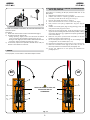
5.2 ADJUSTING THE TRANSMITTED TORQUE
To set the hydraulic system for controlling transmitted torque, turn
the two by-pass screws (Fig. 13).
The red screw controls closing movement torque.
The green screw controls opening movement torque.
To increase torque, turn the screws clockwise.
To reduce torque, turn the screws anti-clockwise.
Fig. 11
4.4 ADJUSTING THE BALANCING SPRING.
IMPORTANT: The barrier is supplied already balanced for the
exact length of the beam indicated in the order.
(The barrier is balanced when the beam stays idle in the 45°
position)
For any fine tuning of barrier balancing, proceed as follows:
1) Make sure that the operator is released: see chapter 6.
2) If the barrier tends to close, turn the spring pre-loading
ring-nut (Fig.12 ref.b) clockwise, if it tends to open, turn it
anti-clockwise.
Fig. 13
5.3 ADJUSTING THE TRAVEL LIMIT SLOW DOWN
For beams with a length of over 4 m, we advise you
not to set too brief a slow down.
1) Adjust the cams of the travel limit device as shown in Fig.14
ref. a by loosing the two Allen screws. To increase the slow
down angle, take the cam close to the relevant travel limit
device. To reduce the slow down angle, take the cam away
from the relevant travel limit device.
2) Set the slow down time of the control unit by adjusting the
dedicated parameters.
3) Relock the system (see chap.6) and run a few operational
tests to verify correct registration of the travel limit devices,
of spring balancing, and of the adjustment of transmitted
force.
Fig. 12
5 START-UP
5.1 CONNECTION TO CONTROL BOARD
IMPORTANT: Before attempting any work on the control board
(connections, maintenance, etc), always turn off power.
Fig. 14
ENGLISH
Observing the indications in fig.3, install the raceways and make
the electrical connections from the electronic appliance to the
selected accessories.
Always separate power cables from control and safety cables
(push-button receiver, photocells, etc.).
Hand over the “User manual” to the customer, as well
as the documentation required by current laws, and
illustrate the correct operation of the barrier, pointing
out the potential danger zones.
RIGHT BARRIER
6 MANUAL MODE OPERATION
OPENING
TRAVEL-LIMIT
DEVICE
If the barrier has to be moved manually due to a power cut or
fault of the automated system, operate the release device with
the supplied key.
The supplied release key can be triangular (Fig. 17 ref.a) or
customised (Fig. 17 ref.b optional).
- Insert the release key in the lock and turn it anti-clockwise
through one complete rev. as shown in Fig. 17.
- Open or close the barrier manually.
ENGLISH
CLOSING
TRAVEL-LIMIT
DEVICE
7 RESTORING NORMAL OPERATION MODE
To prevent an involuntary pulse from activating the gate during
the manoeuvre, cut power to the system before activating the
locking system.
LEFT BARRIER
triangular release key (standard):
-turn the key clockwise until it stops and remove it (Fig. 17
ref. a)
customised release key (optional):
-turn the key clockwise until the point where it can be removed.
(fig. 17 ref. b).
OPENING
TRAVEL-LIMIT
DEVICE
CLOSING
TRAVEL-LIMIT
DEVICE
Fig. 15
5.4 AUTOMATED SYSTEM TEST
After installation, apply the danger sticker on the top of the upright.
Check operating efficiency of the automated system and all
accessories connected to it.
Fig. 17
8 MAINTENANCE
Whenever doing 6-monthly maintenance, always check correct
settings of the by-pass screws, system balancing, and efficiency
of safety devices.
8.1 TOPPING UP OIL
Periodically check the quantity of oil inside the tank.
An annual check is sufficient for low to medium use frequency;
for heavier duty, check every 6 months.
The level must not drop below the notch of the control stick
(Fig.18 ref. a) .
To top-up, unscrew the filling plug (fig.18) and pour in oil up to
correct level.
Use FAAC HP OIL and no other.
Fig. 16
Procedure for converting an RH (LH) version barrier into an LH
(RH) version:
1. Release the barrier as shown in Chap.6.
2. Position the beam in opening position and remove it
from the pocket as shown in Fig. 10 or FIg.11.
3. Re-lock the barrier as shown in Chap.7.
4. Screw the bleed screw on the control unit (FIg.9).
5. Fully loosen the spring adjustment ring-nut (Fig.19
ref.d).
6. Detach the feed pipes (Fig.19 ref.c and f) from the
two pistons and plug the unions.
7. Remove the two pistons (Fig. 19 ref. b and e) from the
upper and lower fittings and reverse their position, taking
the rocker (Fig.18 ref. a). against the opening travel limit
mechanical stop.
8. Remove the pinion pocket and re-install it to set the
barrier at opening as in figure 19.
9. Fit the feed pipes as shown in Fig. 19, according to the
configuration of the barrier (RH or LH).
10. Reverse the travel limit connectors on the control unit.
11. Remove the bleed screw (Fig.9) and carry out the air
bleed operations as indicated in paragraph 8.2.
12. Check the balance of the spring as indicated in
paragraph 4.4.
a
Fig. 18
8.2 BLEEDING OPERATION
If beam movement is incorrect, air must be bled from the
hydraulic system.
Procedure:
1) Make sure that the bleed screw was eliminated (Fig.9)
2) Activate the beam electrically:
- during opening, slightly loosen and re-screw the bleed
screw of the piston with the balancing spring (Fig.1 ref. 33)
- during closure, slightly loosen and re-screw the bleed screw
of the piston without the balancing spring (Fig.1 ref.11).
3) If necessary, repeat the operation several times, until you
obtain correct beam movement.
9 REPAIRS
For any repairs, contact FAAC’s authorised Repair Centres.
LH
RH
4
4
1
1
WHEN THE BARRIER IS OPEN, THE
SPRING MUST NOT BE
COMPRESSED
5
5
2
2
3
6
6
Fig. 19
3
ENGLISH
10 CHANGING THE RH (LH) VERSION OF THE BARRIER INTO
THE LH (RH) VERSION
11 AVAILABLE ACCESSORIES
ANTI-VANDAL VALVE (Fig. 20a)
It protects the hydraulic system if the beam is forced.
AUTOMATIC EMERGENCY RELEASE (Fig. 20b)
During a power cut, the automatic emergency release allows
you to manually lift the beam without accessing the release lever
of the hydraulic control unit. A hydraulic system guarantees that
the beam is stopped in opening position.
Fig. 23
FORK SUPPORT
ENGLISH
The fork has two functions:
- it prevents the beam, when closed, from bending and splitting
if its end is stressed by extraneous forces.
- it allows the beam to rest when closed and thus prevents the
profile bending downward
Fig. 20a
Fig. 20b
SKIRT KIT
The skirt kit increases visibility of the beam.
It is available in lengths 2m and 3m.
Fig. 24
IMPORTANT: If a skirt kit is installed, the balancing spring must
be adapted if possible.
To position the fork support foundation plate, refer to fig.23
where:
P1 = barrier foundation plate
P2 = fork support foundation plate
L = beam length (in mm)
A = Distance between foundation plates
NB.: Dimensions are in mm.
620
360
A = L-240
90
Fig. 21
ARTICULATION KIT (mod. 620 only)
The articulation kit makes it possible to articulate the rigid beam
to a maximum ceiling height of 3.2 m.
71.5
IMPORTANT: If the articulated kit is installed, the balancing spring
must be adapted if possible.
L
640 - 642
A = L-450
90
84
Fig. 22
END FOOT
390
The end foot allows the beam to rest when closed and thus
prevents the profile bending downward.
IMPORTANT: If a foot is installed, the balancing spring must be
adapted if possible.
L
Fig. 25
10
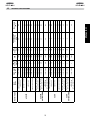
620 R
ARTICULATED
620 R
620 STD
ARTICULATED
620 STD
Barrier model
1,5
2
1,5
2
1,5
2565 / 3815
1500 / 3240
3250 / 4000
1500 / 2740
2750 / 3000
1315 / 2815
1825 / 2815
1825 / 2815
620 RECT. ARTICULATED
A(*)=815/1314 mm.
620 RECT. ARTICULATED
A(*)=1315/1814 mm.
620 RECT.
ARTICULATED
A(*)=1815/2075 mm.
620 ROUND PIVOTING.
620 ROUND
2
2
2
2
1315 / 2555
620 RECTANGULAR
STANDARD
0,75
1825 / 2815
620 RECT.
ARTICULATED
A(*)=1815/2075 mm.
0,75
1825 / 3815
0,75
1825 / 3815
620 RECT. ARTICULATED
A(*)=1315/1814 mm.
620 RECT. ARTICULATED
A(*)=815/1314 mm.
620 ROUND PIVOTING.
1
0,75
3250 / 5000
620 ROUND
1315 / 1815
1
1500 / 3240
1
0,75
2815 / 4815
0,75
1
1815 / 2805
2750 / 3000
0,75
2565 / 4815
1500 / 2740
1
1315 / 2555
620 RECTANGULAR
STANDARD
620 RECT. + SKIRT
Pump
flow-rate
(l/min)
Beam length
(mm)
Beam
profile
2800
2800
2800
1400
2800
1400
2800
1400
2800
1400
1400
1400
1400
1400
1400
1400
1400
1400
1400
1400
1400
R.P.M.
100
100
100
100
100
100
100
100
100
70
70
70
70
70
70
70
70
70
70
70
70
Use
frequency
(%)
2
2
2
3
2
3
2
3
2
80
80
80
100
80
100
80
100
80
200
200
200
150
200
150
200
150
200
150
200
150
Max. torque
(Nm)
ENGLISH
4,5
4,5
4,5
3,5
4,5
3,5
4,5
3,5
4,5
3,5
4,5
3,5
Indicative time
of opening
(sec)
12
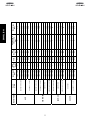
TECHNICAL SPECIFICATIONS
11
642/70
642 R/40
642 STD/40
640
Barrier model
640 RECT. + SKIRT
640 RECT.
620 ROUND PIVOTING
620 ROUND
620 RECTANGULAR
620 ROUND PIVOTING
620 ROUND
620 RECT. + SKIRT
620 RECTANGULAR
640 RECT. + SKIRT
640 RECTANGULAR
Beam
profile
2
3750 / 4240
1
1
0,75
5250 / 7000
3750 / 5740
5750 / 7000
1,5
2
4250 / 5240
1,5
2250 / 3000
2565 / 3815
1500 / 2240
1,5
1315 / 2555
2
2
2750 / 3000
1,5
0,75
1500 / 2740
1500 / 3240
1
3250 / 4000
3250 / 4000
1
0,75
1500 / 3240
1
0,75
0,75
2565 / 3815
2815 / 3815
1
1815 / 2805
0,75
1315 / 2555
1
3750 / 4740
5750 / 7000
1
6750 / 7000
1
1
5250 / 6740
1
1,5
4250 / 5240
5250 / 5740
2
3750 / 4240
4750 / 5240
Pump
flow-rate
(l/min)
Beam length
(mm)
1400
1400
1400
1400
2800
2800
1400
1400
2800
1400
2800
1400
1400
1400
1400
1400
1400
1400
1400
1400
1400
1400
1400
1400
1400
1400
2800
R.P.M.
100
100
100
100
100
100
100
100
100
100
100
70
70
70
70
70
70
70
70
100
100
100
100
100
100
100
100
Use
frequency
(%)
8
8
8
5.5
4
2
3
3
2
3
2
4.5
3.5
4,5
3.5
4,5
3.5
4.5
3.5
8
8
8
8
8
8
5.5
4
Indicative time
of opening
(sec)
470
340
340
250
210
90
110
110
90
110
90
200
150
200
150
200
150
200
150
470
340
340
340
340
340
250
210
Max. torque
(Nm)
ENGLISH