1
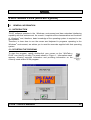
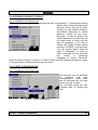
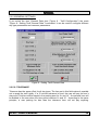
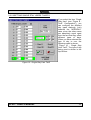
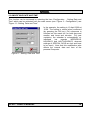
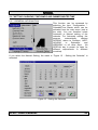
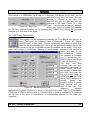
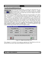
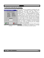
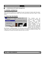
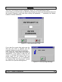
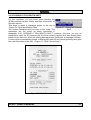
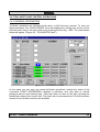
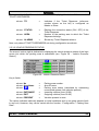
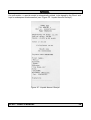
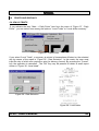
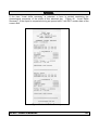
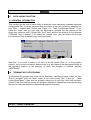
PLUS USER’S MANUAL firmware version TDPLUS1.2XX software version 6.0xx INDEX 1. 1.1 1.2 2. COMMISSIONING........................................................................................................5 MINIMUM REQUIRED HARDWARE CONFIGURATION .........................................5 INSTALLATION OF SOFTWARE .............................................................................5 SOFTWARE PLUS (WINPARK SYSTEM)...................................................................6 2.1 GENERAL INFORMATION .......................................................................................6 2.1.1 INTRODUCTION................................................................................................6 2.1.2 STARTING THE PROGRAM .............................................................................6 2.2 CONFIGURING SYSTEM PARAMETERS ...............................................................8 2.2.1 HARDWARE CONFIGURATION .......................................................................8 2.2.1.1 MODIFYING COMMUNICATION (SERIAL) PORTS......................................8 2.2.1.2 NUMBER OF CONNECTED TICKET DISPENSERS AND HOW TO MODIFY THEIR PARAMETERS ..................................................................................9 2.2.2 MODIFYING MANAGER’S PERSONAL DETAILS ..........................................10 2.2.3 MODIFYING PARKING SYSTEM DATA / AREA DATA ..................................11 2.2.4 OPENING/CLOSING OF AREAS ....................................................................13 2.2.4.1 GENERAL INFORMATION ..........................................................................13 2.2.5 TARIFF CONFIGURATION .............................................................................13 2.2.5.1 GENERAL INFORMATION ..........................................................................13 2.2.5.2 GENERAL SETTINGS .................................................................................14 2.2.5.2.1 TOLERANCE............................................................................................14 2.2.5.2.2 LOST TICKET TARIFF.............................................................................15 2.2.5.2.3 TYPES OF TARIFF CALCULATION ........................................................15 2.2.5.2.4 MAXIMUM DAILY TARIFF .......................................................................15 2.2.5.2.5 HOW THE CONTINUATION THRESHOLD IS USED..............................16 2.2.5.3 SETTING SINGLE STAY USERS’ TARIFFS ...............................................17 2.2.6 MODIFYING DATE AND TIME ........................................................................19 2.2.7 SETTING CALENDAR, TIME BANDS AND SUMMER/WINTER TIME ...........20 2.2.7.1 GENERAL INFORMATION ..........................................................................20 2.2.7.2 SETTING TIME BANDS ...............................................................................21 2.2.7.3 SETTING SUMMER/WINTER TIME ............................................................22 2.2.8 SETTING LANGUAGE AND CURRENCY.......................................................23 2.3 CONFIGURING SOFTWARE PARAMETERS........................................................24 2.3.1 GENERAL INFORMATION..............................................................................24 2.3.2 SELECTING THE PRINTER............................................................................24 2.4 ADMINISTRATOR FUNCTION ...............................................................................25 2.4.1 GENERAL INFORMATION..............................................................................25 2.4.2 PASSWORD MANAGEMENT .........................................................................25 2.4.2.1 MODIFYING THE PASSWORD ...................................................................26 2.4.2.2 ENABLING/DISABLING PASSWORD REQUEST.......................................26 2.4.3 OPERATOR SHIFT MANAGEMENT ...............................................................27 2.4.3.1 ADDING AN OPERATOR ............................................................................28 PLUS – USER’S MANUAL 2 2.4.3.2 CANCELLING AN OPERATOR ...................................................................28 2.5 DAILY OPERATIONS .............................................................................................29 2.5.1 OPENING A TOLL-BOOTH SHIFT..................................................................29 2.5.2 CLOSING A TOLL-BOOTH SHIFT ..................................................................31 2.5.3 TOLL-BOOTH AND CONTROL OPERATIONS...............................................32 2.5.3.1 GENERAL INFORMATION ..........................................................................32 2.5.3.2 VEHICLE PRESENCE STATUS ..................................................................33 2.5.3.3 SHIFT PARTIAL STATEMENTS ..................................................................34 2.5.3.4 PAYMENT FOR A STAY..............................................................................35 2.5.3.4.1 SPECIAL PAYMENTS..............................................................................37 2.5.3.5 LOST TICKET ..............................................................................................39 2.5.3.6 ISSUE OF RECEIPT ....................................................................................39 2.5.3.7 EXIT TOLL-BOOTH PANEL.........................................................................39 2.6 PRINTS AND DISPLAYS ........................................................................................40 2.6.1 DAILY PRINTS ................................................................................................40 2.7 DATA SAVING FUNCTION ....................................................................................42 2.7.1 GENERAL INFORMATION..............................................................................42 2.8 TERMINATING THE PROGRAM............................................................................42 PLUS – USER’S MANUAL 3 INTRODUCTION Explanation of numbering for the software and firmware versions A number with this format is associated with the different versions X.YZZ where: X Y ZZ = Significant implementations counter = Improving implementations counter = Counter for internal use Only variations of X and Y values entail documentation variations. PLUS – USER’S MANUAL 4 1.COMMISSIONING 1.1 MINIMUM REQUIRED HARDWARE CONFIGURATION To operate correctly, the software must be installed on a PC with the following characteristics: • Intel processor (or compatible processors) 80486 DX 100MHz or more • System RAM of at least 8 MB (16 MB recommended if the installed operating system is Windows 95) • Windows 3.11 or Windows 95 operating system is required. • at least 200 MB free space must be available on the hard disk • a PS/2 pointing device (mouse) is recommended, plus a printer and a colour monitor 1.2 INSTALLATION OF SOFTWARE Follow the instructions on the sheet enclosed with the installation diskette. PLUS – USER’S MANUAL 5 2.SOFTWARE PLUS (WinPark System) 2.1 GENERAL INFORMATION 2.1.1 INTRODUCTION “PLUS” software operates in the Windows environment and has a standard interfacing capability with that environment. As a result, it exploits all the characteristics and functions of Windows and, therefore, basic knowledge of the operating system is required to use this software. Therefore, to learn how to use the mouse and keyboard in programs operating in the Windows environment, we advise you to read the manuals supplied with that operating system. 2.1.2 STARTING THE PROGRAM To start the program, rapidly double-click your mouse on the “WinPark++ PLUS” icon (see fig. at side). The mask shown in “Figure 1 - Information mask” appears, showing copyright information and providing information on the currently used version of the program. Figure 1 - Information mask PLUS – USER’S MANUAL 6 The mask disappears automatically after a few seconds, or if you press OK or the Enter key. The mask shown in “Figure 2 - Main Mask” is then shown and is always displayed in the background of the application. Figure 2 - Main Mask The available options are located at the top of the screen (Main, Cash Screen...(F2), Configuration, Administrator, Shifts). You can access them by clicking your mouse over or by typing the underlined letter while pressing the “Alt” key. The software is now being executed, and, if properly connected via the RS422 interface, it can dialogue continuously with the connected peripheral units. PLUS – USER’S MANUAL 7 2.2 CONFIGURING SYSTEM PARAMETERS This function can be accessed through the “Configuration” item which can be activated from the main screen (see “Figure 2 - Main Mask”). From this item, you can select options to activate the wide range of actions we shall describe in detail below. Figure 3 - Configuration 2.2.1 HARDWARE CONFIGURATION Access to modify this parameter is obtained through the item: ‘Hardware & TD’ of the “Configuration menu” (“Figure 3 - Configuration”). This will activate the mask of “Figure 4 - HARDWARE & TD Configuration”. The “TD Disabled” box is not active in this mask as it has no meaning in this context. Figure 4 - HARDWARE & TD Configuration 2.2.1.1MODI FYING COMMUNICATION (SERIAL) PORTS PLUS – USER’S MANUAL 8 In this paragraph we shall examine the “RS422 card Port” and the “User Display Port” fields. In both cases, you have to use the listboxes – activated by pressing on the two arrows on the side of the above items (see fig. at side) – to select the serial port to which the selected device is connected. For the RS422 card, you can select COM1 or COM3, for the User Display, you can select COM2 or COM4. If the RS422 connection is changed, the program must be reinitialised (as announced in a message shown after the modifications are confirmed). 2.2.1.2NUMBER OF CONNECTED TICKET DISPENSERS AND HOW TO MODIFY THEIR PARAMETERS By using the list-box shown at the side, you can select the number of the Ticket Dispensers connected to the system (from 1 to 4). To do this, press the arrow at the side of the field and select the number you require. After this selection, the active Ticket Dispenser fields (see “Figure 5 - TD Parameters”) become active (or are disabled). In this example, one ticket Dispenser only was connected and, consequently, the figure shows that only “Ticket Dispenser 1” parameters are active and can be modified (the others are coloured grey and are therefore inactive). In the “Node nr.” column, you can select the effective number of the Ticket Dispenser node (see paragraph on hardware configuration of the TD card); in the “Area” column, you can select the area controlled by the Ticket Dispenser (see paragraph “2.2.3 MODIFYING PARKING Figure 5 - TD Parameters SYSTEM DATA / AREA DATA”). The fact that the two T.Ds do not have the same node number is obviously controlled (if an error message imposing modification is shown following confirmation). PLUS – USER’S MANUAL 9 2.2.2MODIFYING MANAGER’S PERSONAL DETAILS This function can be accessed through the “Company data” item of the “Configuration” menu. (“Figure 3 - Configuration”). Figure 6 – Company information The above mask is activated. Here you can input and/or modify the details of the system manager. These data are typically shown on the headings of receipts and of some statements. All fields are alphanumeric and their length is restricted to 22 characters, with the exception of the “VAT/ Tax Code “ field which is limited to 16 characters. PLUS – USER’S MANUAL 10 2.2.3 MODIFYING PARKING SYSTEM DATA / AREA DATA This function can be accessed from the “Parking System Data” item in the “Configuration” menu (“Figure 3 - Configuration”). It activates the mask of “Figure 7 - Parking System Data”. Figure 7 - Parking System Data Areas are zones into which the parking system’s total area can be logically subdivided (up to a maximum of 4). The number of present areas can be selected by inputting the number (from 1 to 4) in the “Areas present” box. Data of the selected area are shown at the bottom of the mask. You can vary the selected area by clicking on the area you require (see figure above). You can input a identification name – the one shown in the mask of “Figure 28 - TOLLBOOTH Panel” next to each TICKET DISPENSER - for the selected area in the “Area Name” field. The “Ticket Heading” field accepts various alphanumeric values and contains the “text” to be printed on the ticket issued by the Ticket Dispenser. You can input a free text of a maximum of 14 characters in this field. As regards the “sub-title”, i.e. the words at the bottom of the ticket, you can select three different types to ticket. If “Ticket Type” is set to PLUS – USER’S MANUAL 11 “Standard Sub-title”, the ticket will show the standard wording preset on the Ticket Dispenser firmware (i.e. KEEP THIS TICKET AND CHANGE IT FOR THE “EXIT TOKEN” AT THE TOLL-BOOTH “PSFAAC PLUS SYSTEM”). If “Ticket Type” is set to “No Subtitle”, no sub-title will be shown. Lastly, If “Ticket Type” is set to “With programmable Subtitle”, the fields for notes 1,2,3 and 4 will become active. In these fields, you can input free text up to a maximum of 28 characters per line, and they will be printed at the bottom of the ticket according to order. The notes are printed aligned on the left. If you confirm the “With programmable Sub-titles” choice, and leave all four notes blank, a warning message is shown when you confirm or when the area is changed. However, you may nevertheless proceed (in this case, i.e. if the notes are left blank, the end result is the same as if the “No Sub-titles” option had been selected). If you compile the notes and then decide to select an option other than “Programmable Sub-titles”, the edit fields referring to the notes are disabled, but the program nevertheless stores the written notes for possible future use. In the “Parking Capacity” field, you can input a numeric value indicating the maximum number of vehicles the area can contain. The “Entered”, “Exited” and “Present” fields indicate vehicle flow data. These values are dynamically updated at each transit and according to the data received by the Ticket Dispensers – however, you can modify these data and, in this case, they will be sent to the connected Ticket Dispensers which will be updated with the new values. The difference between the value of the “Parking capacity” field and the “Present” field sets the area’s free or full status according to whether it is greater than or equal to 0. If the car park is full, all Ticket Dispensers controlling the area are also put into “FULL” status, and therefore, will not issue any more tickets until they return to “FREE” status. PLUS – USER’S MANUAL 12 2.2.4OPENING/CLOSING OF AREAS 2.2.4.1GENERAL INFORMATION This function can be accessed by selecting the item “Configuration – Opening and Closing Areas” which can be activated from the main screen (see fig. at side). Closing an area means making it inaccessible (whatever its vehicle presence status at the time). Therefore, in case of closing, the Ticket Dispensers for that area will no longer issue a ticket until the area is reopened. If an area is closed, the CASH Screen shows the word “CLOSED” over that area. You can choose which areas (all areas if necessary) to close or open. If the area is (or all the areas are) closed, a confirming messages is shown. Obviously, when an area is closed, it remains in "closed” status until the operator decides to reopen it, using the above mentioned menu item as usual. 2.2.5 TARIFF CONFIGURATION 2.2.5.1GENERAL INFORMATION This function can be accessed by selecting the item “Configuration – Tariffs”, which can be activated from the main screen (see fig. at side). You can then select the item “General Data” or “Single stay Use”. Figure 8 - Tariff Configuration PLUS – USER’S MANUAL 13 2.2.5.2GENERAL SETTINGS If you select the item “General Data (see “Figure 8 - Tariff Configuration”) the mask “Figure 9 - Setting Tariff General Data” is activated. It can be used to configure different day type parameters and common parameters. Figure 9 - Setting Tariff General Data 2.2.5.2.1TOLERANCE Tolerance has the same effect for all day types. The time set in this field makes it possible not to apply the tariff rigidly. If a 15 minute tolerance is fixed, the user will pay an hour’s stay even if his/her vehicle stayed in the parking area for 1h and 14’ - the second hour will be debited to the user when the time period reaches 1h and 16’. According to the same principle, a user parking for less than the tolerance time, will not pay anything. PLUS – USER’S MANUAL 14 2.2.5.2.2LOST TICKET TARIFF This tariff is applied if the user is unable to produce the start of parking time ticket (see paragraph “2.5.3.5 LOST TICKET”). In this case too, there is no difference as regards type of day. 2.2.5.2.3TYPES OF TARIFF CALCULATION The tariff can be calculated in two different ways (see fig. at side). If the “day” mode is selected (from 0 to 24 hours), the day is considered as the time interval between 00:00 and 24:00 and, therefore, the max. daily tariff is effective in this interval, after which time is calculated a new. If the “24 hours from start of parking time” mode is selected, the following interval is considered as a virtual day: the interval commencing from start of parking time calculated at the time plus 24 hours added to the beginning. The maximum daily tariff is applied to this interval (if, for example, a Client begins parking at 14.30 hours of 18th March, his/her virtual day ends at 14.30 hours of 19th March). 2.2.5.2.4MAXIMUM DAILY TARIFF As we said in the previous paragraph, a different amount is used for the Maximum Daily tariff according to which of the two tariff calculation methods are chosen. In this case of “Day” calculation (from 0 to 24), the amount input in the “Maximum Daily tariff for day calculation” (according to day type) is used. Obviously, four different amounts have to be calculated for the four different day types (this is done by clicking the different types and inputting the amount in the appropriate field). In the case of “24 hour (from start of parking time)” calculation, the amount input in the “Maximum Daily tariff (one only) for 24 hour calculation” is used. In this case, there is only one amount as the operation covers two different days which may or may not be of several different types. PLUS – USER’S MANUAL 15 2.2.5.2.5HOW THE CONTINUATION THRESHOLD IS USED As the figure at the side shows, you can select the way the program operates at every band change (when the tariff is being calculated). If the “from the first threshold” mode is selected, whenever the band is changed, the program will start from the first threshold of the band. If, instead, the “with continuation threshold” mode is selected, the calculation will be effected by using the continuation threshold (if the normal threshold hours are exceeded). Let’s suppose, for example, that “Band I” (set from 00:00 to 08:00) is configured as a single 60 minute threshold and continuation threshold of 60 minutes and that “Band II” (set from 08:00 to 13:00) is configured as a single 30 minute threshold and continuation threshold of 60 minutes. In this case, if we assume that parking starts in the interval of Band I (e.g. at 06.30), the tariff calculation will apply the values set for the first 60 minutes of Band I and, therefore, will use the values of the continuation threshold of Band I (and the calculation would take us to 08.30). As we have passed into Band II, the calculation uses the value of the first threshold of Band II (for 30 minutes) if the “from first threshold” flag is set, or it uses the value of the continuation threshold if the “with continuation threshold” flag is set. PLUS – USER’S MANUAL 16 2.2.5.3SETTING SINGLE STAY USERS’ TARIFFS If you select the item “Single Stay User” (see “Figure 8 Tariff Configuration”) you can configure the different day types distinctly. Let’s examine the “WEEKDAY” case, since the other cases are absolutely equal apart from the fact that they affect different types of days. When you have selected the type of day to use, the following mask is shown: “Figure 10 - Single Stay User Tariff”. The type of day being used is shown in the top left box. Figure 10 - Single Stay User Tariff PLUS – USER’S MANUAL 17 You can directly configure up to 11 different thresholds in terms of both duration (in minutes) and tariff for the selected interval. Furthermore, the duration and amount of the “continuation tariff” must be configured – this tariff becomes active when the hours specified in the preceding thresholds have been exceeded. The fact that every threshold must be greater than set tolerance (see paragraph “2.2.5.2.1 TOLERANCE”) is controlled. The band being used can be seen in the part on the right (see fig. at side). The band can be modified by clicking on the “Band I” and “Band II” etc. boxes. As a result, the threshold values displayed on the right will vary. The time interval during which a band is active is also shown for each selected band. This interval, as well as other specific parameters of the bands, can be configured in detail (see paragraph “SETTING TIME BANDS”). If you confirm (with the OK key) the modifications become active (for all bands) whereas, in case of cancellation, the previous values are restored (for all bands as ever). PLUS – USER’S MANUAL 18 2.2.6MODIFYING DATE AND TIME This function can be accessed by selecting the item “Configuration - Setting Date and Time” which can be activated from the main screen (see “Figure 3 - Configuration”) see “Figure 11 - Setting Date and Time”. In the example, the setting is 10 April 2000 at 15:29. The setting is stored when confirmed (by pressing the OK key). Full coherence is checked on this mask too, for both days and months, and hours and minutes. For year variations, the calendar is automatically reinitialised (as regards WEEKDAYS, HOLIDAYS and HALF-HOLIDAYS, whereas settings of SPECIAL DAYS are lost and have to be reset). Note that this modification also affects the internal date and time of the personal Computer. Figure 11 - Setting Date and Time PLUS – USER’S MANUAL 19 2.2.7 SETTING CALENDAR, TIME BANDS AND SUMMER/WINTER TIME 2.2.7.1GENERAL INFORMATION This function can be accessed by selecting the item “Configuration – Calendar/Time Bands which can be activated from the main menu (see at the side). You can therefore select Automatic or Manual setting of the calendar. For Automatic setting, the program automatically assigns HOLIDAY status to Sundays, HALFHOLIDAY to Saturdays, and WEEKDAY to all other days. No SPECIAL day is preset (to cater for different requirements in different countries). If you select the Manual Setting, the mask in “Figure 12 - Setting the Calendar” is activated. Figure 12 - Setting the Calendar PLUS – USER’S MANUAL 20 When the mask appears, the current day is preset (in the case of the example, 10 April 2000 which is a WEEKDAY as it falls on a Monday. The Month to be used can be selected on the left of the mask. The day number is selected at top right. The required day type for that day can be selected in the area “Figure 13 - Day Type” . All inputted variations become Figure 13 - Day Type active only when confirmed (by pressing the OK key) whereas deletion (i.e. by pressing the “Cancel” key) affects all variations effected up to that time in this mask. 2.2.7.2SETTING TIME BANDS This function can be accessed by pressing the “Time Bands” key (see fig. at side). This done, the following mask is displayed: “Figure 14 - Bands Specific Data”. In this mask, you can set specific parameters of each time band for the selected day type. First of all, the number of bands a day (of the selected type, shown at top left) is divided into can be modified on this mask. To do this, select the number in the list-box “Number of active bands”. Whenever the number is varied, the data of the non-considered bands are enabled or disabled (e.g. if 2 bands were set, data for Band I and Band II only will be active). The Start and End columns (on the left, separated according to band) contain the hour and minutes of band Start and End. Note that the first band must begin at 00:00 and the last must end at 24:00. Moreover, if several bands are present, end of one band must coincide with the start of the next. The Figure 14 - Bands Specific Data maximum amount applicable to the band referred to is shown at the right of the mask (“Max. Tariff for band”). Coherence of Start and End times is controlled when a band is changed or by pressing the OK key. In the event of cancellation, all modifications effected on this mask are cancelled. PLUS – USER’S MANUAL 21 2.2.7.3SETTING SUMMER/WINTER TIME This function can be accessed by pressing the “Sum/Wint time” key (see fig. at side). This will display the mask of “Figure 15 - Setting Summer/Winter time” in which you can set the summer time activation date and the winter time restore date, as well as change of time when summer time is activated (typically 1 hour). When summer time is activated, this “moves forward” the time clock shown in the “Move time…” box. Therefore, in the example below, the clock is shifted forward by 1 hour at 02:00 of 31 March, i.e. the time becomes 03:00. Restoring winter time “moves back” the clock. Therefore, in the example, the clock is moved back by 1 hour at 03:01 of 25 October, i.e. the time becomes 02:00. All this is important for stays begun before Summer time was activated and finishing after such activation, and for stays begun before winter time was restored and finishing after it was restored. In fact, in the first case, the system automatically subtracts an hour’s stay as it was never used. In the second case, the system automatically adds an hour’s stay. Important: this operation is carried out only if the program is being executed at these times. If the PC is switched off or the program is not being executed, time must be changed manually. Figure 15 - Setting Summer/Winter time Data coherence is controlled in this mask too, regarding both Days/Months and the fact that WINTER time restore date follows SUMMER time activation date. PLUS – USER’S MANUAL 22 2.2.8SETTING LANGUAGE AND CURRENCY This function can be accessed by selecting the item “Configuration – Language & Currency” which can be activated from the main mask (see “Figure 3 Configuration”). This done, the following screen is displayed: “Figure 16 - Setting language and currency”. In this screen you can select one of the available languages and the currency symbol to be used in all reports indicating amounts. Note that the decimal point in the amounts is activated when selecting a language other than Italian. In the example, only the Italian language can be selected, because the other selection buttons are disabled. In general, only languages whose buttons are active (in BLACK) can be selected, depending on which language versions of the software are installed on the hard disk. Important: a language change becomes effective when Figure 16 - Setting language and the program is restarted (as indicated by a message shown when the confirming command is given). currency PLUS – USER’S MANUAL 23 2.3 CONFIGURING SOFTWARE PARAMETERS 2.3.1GENERAL INFORMATION These functions enable you to configure the way the program interacts with the printer. They can be accessed with the “Main” item of the main screen menu (see “Figure 2 - Main Mask”). 2.3.2SELECTING THE PRINTER This function can be accessed by selecting the item “ Main – Printer Selection” from the main screen (see “Figure 17 Printer Selection”). A list of printers installed in the system is shown on the right of the screen (to install other Figure 17 - Printer Selection printers, see the manual of the Windows operating system). The currently activate printer is marked with the letter v Using your mouse, locate the arrow on the printer you require and select by clicking. This configuration is saved automatically when the menu is closed. PLUS – USER’S MANUAL 24 2.4 ADMINISTRATOR FUNCTION 2.4.1GENERAL INFORMATION These functions refer to management of the system’s security and are, therefore, assigned to what is known as the “Administrator”. This manages operators authorised to open toll-booth shifts (thus defining them both as an ID and password) as well as modifying and enabling the Password Figure 18 - Administrator required to carry out some special operations. The Administrator is accessed from the “Administrator” item of the main screen menu (see “Figure 18 - Administrator”). 2.4.2PASSWORD MANAGEMENT The PASSWORD is set to active status at installation and is: FAACPLUS We should stress that the upper and lower case characters have different meanings. If the Password is active, it has to be used when special functions requiring particular attention have to be executed, such as all configuration functions. If these functions have to executed often or if this control is not required, they can be disabled with the Password itself. PLUS – USER’S MANUAL 25 2.4.2.1MODIFYING THE PASSWORD Figure 19 - Modifying the PassWord This function can be activated by selecting the item “Administrator – Change PassWord” of the main menu (see “Figure 18 - Administrator”). This done, the following screen is displayed: “Figure 19 Modifying the PassWord”. To modify the Password, input the old password and then type in the new one twice (for security purposes). Note that when you type in characters, they are shown as asterisks. Actual modification is effected when you confirm (by pressing the OK key). We must stress that if modifying, you must take a note of the modified Password. 2.4.2.2ENABLING/DISABLING PASSWORD REQUEST This function can be activated by selecting the item “Administrator – Enable/Disable PassWord” from the main screen menu (see “Figure 18 Administrator”). This done, the following mask is displayed: “Figure 20 - Enabling / Disabling Password”; this is the same screen displayed when you have to modify some special Figure 20 - Enabling / Disabling Password functions (see paragraph ”2.4.2 Request PASSWORD MANAGEMENT” ). Input the current Password here and confirm with the OK key. The Password request is then enabled if it had been disabled and, vice versa, is disabled if it had been enabled. Note that you are not allowed to make more than two mistakes (the number of attempts are indicated at top left of the mask) – at the third attempt, the system cancels the mask. PLUS – USER’S MANUAL 26 2.4.3 OPERATOR SHIFT MANAGEMENT This function can be activated with the item “Administrator – Cashier Management (see “Figure 18 Administrator”). This done, the following mask is displayed: “Figure 21 - Shift Management”. In this mask, the Administrator can input new operators with the “Add” key or cancel the displayed Operator with the “Eliminate” key, or modify the Passwords Figure 21 - Shift Management of present operators by selecting ID from the list-box on the left (CASHIER ID) and then typing the required PASSWORD in the field on the left. PLUS – USER’S MANUAL 27 2.4.3.1ADDING AN OPERATOR This function can be activated by pressing the “Add” key (see fig. at side). This done, the following mask is displayed: “Figure 22 - Inputting an ID”. In this mask, you can type in an ID number for the new operator. Note that, on confirming, the ID is checked to see if it is different from all previous IDs. If it is not, an appropriate error message is shown and the user cannot continue until a different ID is input. The Password for the new operator is preset to the value “PASSWORD”. Figure 22 - Inputting an ID 2.4.3.2CANCELLING AN OPERATOR This function can be activated by pressing the “Eliminate” key (see fig. at side). This done, a confirming message is requested. The operator shown in the mask “Figure 21 - Shift Management” at that moment is eliminated: PLUS – USER’S MANUAL 28 2.5 DAILY OPERATIONS 2.5.1OPENING A TOLL-BOOTH SHIFT A shift must be “OPENED” to enable an operator to carry out the normal toll-booth operations. To open a toll-booth shift, you can either press function key <F3> or select the item “Shifts” and then “Open shift” on the main screen ” (see “Figure 23 - Opening a Tollbooth Shift”). PLUS – USER’S MANUAL Figure 23 - Opening a Tollbooth Shift 29 This done, the following mask is displayed: “Figure 24 - Shift Identification Data” In this mask, you have to input a valid ID (by moving the cursor over the white boxes) and the correct Password (note that while writing the password, “*” (asterisks) are shown instead of normal characters. Figure 24 - Shift Identification Data If you type the correct data and press the OK key, the shift is opened and the program displays a confirming message (see “Figure 25 - Shift Opening Message”). If you press the Cancel key, the action is abandoned. If the typed in data are not correct, a message warning of the error is shown (both for not existent IDs and incorrect Passwords). For an explanation on inputting IDs and Passwords, consult the section on Operator Management. PLUS – USER’S MANUAL Figure 25 - Shift Opening Message 30 2.5.2CLOSING A TOLL-BOOTH SHIFT For this operation, you can either press function key <F10> or select the item “Shifts” and then “Close shift” on the main screen. This done, a mask is displayed similar to the one in Figure 26 - Closing a Toll-booth “Figure 24 - Shift Identification Data” . The correct Password must be input in this mask. The Shift operations are the same as those mentioned in paragraph “2.5.1 OPENING A TOLL-BOOTH SHIFT”; however, this time, you are not prompted to input the ID, because the ID of the currently opened shift has already been preset. In this case too, when the closing data have been confirmed, a message is shown. A note is then automatically printed, indicting shift data (ID and opening/closing time) plus the cash flow totals of the shift (“Figure 27 - Shift Closure Note”). Figure 27 - Shift Closure Note PLUS – USER’S MANUAL 31 2.5.3TOLL-BOOTH AND CONTROL OPERATIONS 2.5.3.1GENERAL INFORMATION Toll-booth operations are effected strictly when a shift has been opened. To carry out these operations, the “CASH SCREEN” must be displayed by clicking your mouse on the relevant menu item of the main mask or by pressing function key <F2>. The mask shown below will appear (“Figure 28 - TOLL-BOOTH Panel”). Figure 28 - TOLL-BOOTH Panel In this mask, you can carry out normal toll-booth operations, monitor the status of the connected TICKET DISPENSERS (updated in real-time), and view data on vehicle presence status of the parking area. Note that there is a box on the right, showing the identification data of the current shift. This mask can be accessed even if a shift has been closed, but all toll-boot functions are disabled. PLUS – USER’S MANUAL 32 The zone at top left of the mask is dedicated to displaying the status of the connected TICKET DISPENSERS: column: TD → Indicates if the Ticket Dispenser (reference number shown on the left) is configured as Master or Slave. column: STATUS → column: AREA → column: ALARMS → Displays the connection status (ON / OFF) of the Ticket Dispenser. Number of the parking area to which the Ticket Dispenser belongs. Shows any Ticket Dispenser alarms. Note: only data of TICKET DISPENSERS set during configuration are shown. 2.5.3.2 VEHICLE PRESENCE STATUS The area at bottom right is dedicated to displaying the vehicle presence status of the logic zones into which the parking area is subdivided (see “Figure 29 - Vehicle Presence Status”). Figure 29 - Vehicle Presence Status Key to fields: column: No column: Area Name → → Parking area number. Area ID name. column: → column: ENTRANCE column: EXIT column: PRESENT → → → Parking area status (calculated by subtracting unoccupied spaces from vehicles present) Incoming vehicles (from 00:00). Outgoing vehicles (from 00:00). Vehicles present in area. The values indicated obviously depend on initial conditions and on on-going transits (both in and out). However, they can be varied with the function: “Configuration – Parking Area Data”. PLUS – USER’S MANUAL 33 2.5.3.3SHIFT PARTIAL STATEMENTS At any time (when a shift has been opened), partial data referring to the current shift can be displayed. Just press “Part.Shift” (see fig. at side). This done, the following mask is displayed: “Figure 30 - Shift Partial Data”; this mask shows shift identification data (ID and starting date/time) and – on the left – the number of payment transactions effected subdivided per type. The total amount of cash collected is also shown. Figure 30 - Shift Partial Data Note that, when a shift has been opened, the number of payers for the current shift (see fig. at side) is always shown in the mask: “Figure 28 - TOLLBOOTH Panel” (at top left under the zone displaying current date and time). If the shift is closed, “TOTAL PAYERS” will instead be shown in the same zone i.e. payers of the current day (from 00:00 hours). PLUS – USER’S MANUAL 34 2.5.3.4PAYMENT FOR A STAY The payment for a stay is effected by pressing the “Stay Pay” key (see fig. at side) or by just pressing the <ENTER> key. This done, the following mask is displayed: “Figure 31 - Ticket Code Acquisition”. At this point, the operator must acquire – with the scanner - the barcode printed on the ticket issued to the Client on entering the parking area. If the scan fails (due to a ruined ticket or malfunctioning barcode reader), the numeric code printed on the ticket can always be input manually (in this case, the program automatically checks if the inputted code is coherent). Figure 31 - Ticket Code Acquisition After the code has been input, and the OK (or <ENTER>) key is pressed, the mask of “Figure 32 - Payment Confirmation” is displayed, showing the summary data for the stay. PLUS – USER’S MANUAL 35 Figure 32 - Payment Confirmation The mask clearly shows the salient data of the stay: start and end time, overall duration of stay (in days, hours and minutes), and amount due calculated automatically according to the tariffs set in the configuration. By pressing <ENTER> or the OK key, cash payment is confirmed and issue of the receipt is enabled. The “Cancel” key cancels the operation. PLUS – USER’S MANUAL 36 2.5.3.4.1 SPECIAL PAYMENTS This function can be activated by pressing the “Special” key (see fig. at side). This done, the following mask is displayed: “Figure 33 - Special Payments”. In this mask, the operator must select the type of payment (from the available options). In all cases, the transaction is recorded taking into account the selected type (see paragraph “2.5.3.3 SHIFT PARTIAL STATEMENTS”). Figure 33 - Special Payments If you select “Credit Card” or “Cheque” execution is quite normal. The only particular case, is “Unpaid Amount”: the typical case whereby the Client does not have enough cash to pay the amount; in this case, i.e. the Client selects this option and presses OK, the following mask is displayed: “Figure 34 Personal data Inputting”. The Client’s personal data must be input in this mask. Figure 34 - Personal data Inputting PLUS – USER’S MANUAL 37 On confirmation, a special receipt is automatically printed, to be signed by the Client and kept for subsequent reimbursement (see “Figure 35 - Unpaid Amount Receipt”). Figure 35 - Unpaid Amount Receipt PLUS – USER’S MANUAL 38 2.5.3.5LOST TICKET This function can be activated by pressing the “Lost Ticket” key (see fig. at side). This happens when the Client cannot produce the ticket (issued by the TD on entry to the parking area) certifying start of stay. On activation, the same mask is displayed as in “Figure 32 - Payment Confirmation”, while the amount input at configuration is shown (note that the stay start and end data are on zero as they cannot be calculated). If you press the OK key, a further confirmation is requested before the operation is executed. 2.5.3.6ISSUE OF RECEIPT When a payment has been made, the “Receipt” key is activated – if it is pressed, the Receipt for the payment is issued. After a receipt has been issued, the same receipt cannot be re-issued because the key is automatically disabled. Figure 36 - Receipt 2.5.3.7EXIT TOLL-BOOTH PANEL To exit the CASH Screen press the key at the side or the <Alt> key on the keyboard and the letter ‘E’. In this way you return to the main screen of “Figure 2 - Main Mask”. PLUS – USER’S MANUAL 39 2.6 PRINTS AND DISPLAYS 2.6.1DAILY PRINTS If you activate the item “Main → Daily Prints” item from the menu of “Figure 37 - Daily Prints” , you can select from among the options: “Local Totals” or “Local shifts summary”. Figure 37 - Daily Prints If you select “Local Totals”, a summary is printed of transactions effected on the selected day by means of the mask in “Figure 39 - Date Selection”. In this mask, the user must input the day of which s/he requires a print (in ddmmyy format). By pressing the “Cancel” key, the operation is cancelled. The “OK” key may be pressed to obtain a small report shown in “Figure 38 - Local totals”. Figure 39 - Date Selection Figure 38 - Local totals PLUS – USER’S MANUAL 40 If the item “Local shifts summary” is selected, a form is printed containing the chronological sequence of the shifts of the selected day “Figure 40 - Local Shifts Summary”. If the report is requested during an opened shift, it will NOT contain data of the current shift. Figure 40 - Local Shifts Summary PLUS – USER’S MANUAL 41 2.7 DATA SAVING FUNCTION 2.7.1GENERAL INFORMATION This function can be used to save (copy on diskette) some particularly important data and configuration files. It can be accessed from the menu of the main screen by selecting the item “Main – Load/Unload Tables (see “Figure 41 - Table Load/Unload Menu”). If you select the “Load” item, you can copy the following on diskette: the file referring to the single stay collection tariff (“Single Stay Tariff” item) and the file referring to the calendar (“Calendar” item). Likewise, if you select the “Unload” item, you can restore the files we just mentioned from a diskette copy made previously. Figure 41 - Table Load/Unload Menu Note that, if you wish to make a full copy of all the system files (i.e. of the program system), you just have to make a backup copy (e.g. by means of the appropriate facility of the operating system) of the directory in which the program is installed (typically <WINPARK>). 2.8 TERMINATING THE PROGRAM To terminate the program and return to the Windows operating system, select the item “End of program” from the “Main” menu of the main screen (see “Figure 41 - Table Load/Unload Menu”). Note that the program allows you to exit only if the shift has been closed. If the shift was not closed, the program displays an appropriate message warning the user to close the shift before terminating program execution. PLUS – USER’S MANUAL 42 INDEX OF ILLUSTRATIONS Figure 1 - Information mask .................................................................................................6 Figure 2 - Main Mask ...........................................................................................................7 Figure 3 - Configuration .......................................................................................................8 Figure 4 - HARDWARE & TD Configuration ........................................................................8 Figure 5 - TD Parameters ....................................................................................................9 Figure 6 – Company information........................................................................................10 Figure 7 - Parking System Data .........................................................................................11 Figure 8 - Tariff Configuration ............................................................................................13 Figure 9 - Setting Tariff General Data................................................................................14 Figure 10 - Single Stay User Tariff.....................................................................................17 Figure 11 - Setting Date and Time....................................................................................19 Figure 12 - Setting the Calendar........................................................................................20 Figure 13 - Day Type .........................................................................................................21 Figure 14 - Bands Specific Data ........................................................................................21 Figure 15 - Setting Summer/Winter time ...........................................................................22 Figure 16 - Setting language and currency ........................................................................23 Figure 17 - Printer Selection ..............................................................................................24 Figure 18 - Administrator ...................................................................................................25 Figure 19 - Modifying the PassWord..................................................................................26 Figure 20 - Enabling / Disabling Password Request ..........................................................26 Figure 21 - Shift Management ...........................................................................................27 Figure 22 - Inputting an ID .................................................................................................28 Figure 23 - Opening a Toll-booth Shift...............................................................................29 Figure 24 - Shift Identification Data....................................................................................30 Figure 25 - Shift Opening Message ...................................................................................30 Figure 26 - Closing a Toll-booth Shift ................................................................................31 Figure 27 - Shift Closure Note ...........................................................................................31 Figure 28 - TOLL-BOOTH Panel .......................................................................................32 Figure 29 - Vehicle Presence Status .................................................................................33 Figure 30 - Shift Partial Data..............................................................................................34 Figure 31 - Ticket Code Acquisition ...................................................................................35 Figure 32 - Payment Confirmation .....................................................................................36 Figure 33 - Special Payments...........................................................................................37 Figure 34 - Personal data Inputting....................................................................................37 Figure 35 - Unpaid Amount Receipt...................................................................................38 Figure 36 - Receipt ............................................................................................................39 Figure 37 - Daily Prints ......................................................................................................40 Figure 38 - Local totals ......................................................................................................40 Figure 39 - Date Selection .................................................................................................40 Figure 40 - Local Shifts Summary......................................................................................41 Figure 41 - Table Load/Unload Menu ................................................................................42 PLUS – USER’S MANUAL 43 Printed in Italy by Faac S.p.A. via Benini, 1 40069 Zola Predosa (BO) 12 November 1998