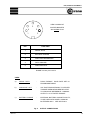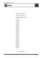
1
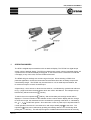
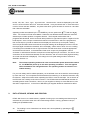
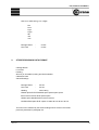
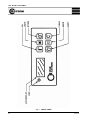
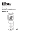
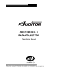
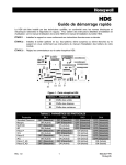
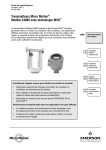
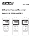
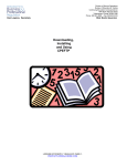
DTS, DTS-W and DTW Mk II MAN 432 : Issue 3 User Manual CRANE ELECTRONICS LTD NOTICE ALL RIGHTS RESERVED. Reproduction of any part of this manual in any form whatsoever, without the prior permission in writing from Crane Electronics Ltd is forbidden. Copyright © June 2011 by Crane Electronics Ltd The contents of this manual are subject to change without prior notice. Approved By: Date: 06 / 06 / 11 DTS, DTS-W and DTW Mk II CONTENTS Page C E Marking 3 Operating Modes 4 Data Storage, Viewing and Printing 5 Programming 6 Output Connections 8 Battery Replacement 8 SPECIFICATIONS Torque range Accuracy Serial Output Analogue Output Battery Types & Life Environmental 9 9 10 10 10 10 APPENDIX Serial Data Format Single Reading Data Formats Stored Readings Data Format 11 11 12 FIGURE SHEETS Fig 1 : Front Panel Fig 2 : Output Connections Fig 3 : Page Printout Issue 2.0 13 14 15 2 DTS, DTS-W and DTW Mk II C E MARKING Manufacturer: Crane Electronics Ltd Address: Watling Drive Sketchley Meadows Hinckley Leicestershire LE10 3EY United Kingdom Tel: +44 (0)1455 251488 Declares that this product has been assessed and complies with the requirements of the relevant CE Directives. 3 Issue 2.0 DTS, DTS-W and DTW Mk II 1. OPERATING MODES The DTS is a digital torque screwdriver with an attached display. The DTS-W is a digital torque wrench with an attached display. The DTW is a digital torque wrench with an integrated display. All 3 products have an identical display and keypad. In this manual where a reference is made that could apply to any of the units, the term DTWS will be used. The DTWS will give readings over a wide range of torques. When selecting a DTWS for a particular application, choose the lowest rated unit that will achieve the necessary torques with a small safety margin. The DTWS may be used down to 10% of rated torque and below, but for minimum torque to 15-20% of rated torque. All panel keys, which are two or three function switches, are indicated by symbols and reference to Fig. 1 page13 will show the descriptions which are used in this Manual. For example the top left hand key will be known as the ON key. To switch the unit on operate the ON key, after a short delay a three digit number will be displayed. This is an indication of the software version number and the display will then change to show zero torque, the measurement units and also the operating mode which is indicated by the Peak/Track symbol. Since auto zero occurs on power-up it is important that for / normal operation the wrench is not switched on with torque already applied to the drive. The required units of use can be selected by pressing and holding down the CLEAR key while pulsing the UNIT key. This will step through the available selections and these will normally Issue 2.0 4 DTS, DTS-W and DTW Mk II be ftlb, inlb, Nm., Ncm., kgm., kgcm and ozin. Note that ozin. cannot be displayed by the LCD and if no units are shown then ozin. has been selected. It may be noticed that on some wrenches not all of these units are available, only those units which give a full scale of more than 1 and less than 1500 are selectable. Operating modes are selected by the MODE key, the two options are Peak and Track. Two versions of Peak are available. Peak with Auto Reset and also Peak with maximum stored torque of either positive or negative direction. The first peak mode works with a programmable threshold, which can be set either positive for right-hand torques or negative for lefthand torques. Once a torque exceeds the threshold in the direction in which it is programmed, then a new torque cycle will be started and the display will increment up to the peak reading. Once torque has fallen below the threshold, that peak reading will be displayed until such time as the torque again exceeds the threshold, when the display will be reset to show the new reading. If a reading has exceeded the low or high levels the LED will show Green or Red as appropriate and the buzzer will sound. In the alternative Peak mode torque may be applied in either a clockwise or anticlockwise direction as required until the target torque is reached. The wrench and screwdriver do not discriminate between the two directions, and do not auto reset (highest reading since last manual reset is displayed). The change from one peak storage mode to another is detailed in Section 3.2. Note: The selected operating modes and units are stored after power-down and at switch on, the DTWS will power-up in the same operating conditions. This also applies when the batteries are changed because the operating modes are stored in nonvolatile memory. For your own safety and for reliable operation you are advised never to exceed the nominal ratings by more than 10%. Do not operate the DTWS without first switching on so that this instruction may be followed. Adopt a firm stance when operating the DTW in case the tool slips. Do not snatch at the DTW but use a steady continuous movement. The DTWS should be calibrated at intervals not exceeding twelve months, therefore, return it to your supplier or directly to Crane Electronics, who also offer a repair service. In the event of difficulties your supplier should be contacted for advice. 2. DATA STORAGE, VIEWING AND PRINTING DTWS Mk II has a non-volatile memory capable of storing up to 100 readings and these may be entered at any time from either of the two Peak storage modes. Having generated a torque reading two possibilities exist :- 2a. 5 The reading is to be cleared and not stored, this is accomplished by operating the CLEAR key. Issue 2.0 DTS, DTS-W and DTW Mk II 2b. The reading may be both stored and sent to the RS232 serial output port, this is accomplished by pressing the STORE key. In this way it is possible to build up stored data of valid torque cycles only, without the necessity of clearing from memory any false reading that may have occurred. Stored data may be erased or viewed by pressing the SHIFT and MODE keys simultaneously and then releasing. The display will now be blank and in this mode pressing the CLEAR key will erase all stored data. Alternatively pressing STORE key will display the oldest reading in the memory and then automatically scroll through each subsequent reading until after the final one, the display will revert to the 'Data Storage' mode. Concurrently the stored readings are sent to the RS232 output port and the data stored in memory is retained. It should be noted that if there is no stored data, entry into this mode is inhibited. If the SHIFT key is pressed and held whilst pressing the STORE key then the stored data is displayed and output in page format via the RS232 serial port to a printer. Included in this data is the Serial Number, rating and Calibration due date. Each stored reading is then displayed in turn and output to the RS232 serial port and the data stored in memory is retained. A sample printout is shown in Fig. 3 / Page 15. 3. PROGRAMMING 3.1 The set-up data can be input by entering into the sequential programme mode and different parameters may be entered in turn. To enter the programming mode operate SHIFT and UNIT keys, thereafter, operate the UNITS key to move through the various functions. The parameter to be changed is indicated by either a flashing LED or number. To exit from the programming mode operate the MODE key. 3.2 The first parameter to be adjusted is the threshold and the correct mode is indicated by the LED flashing Yellow. To select the non-auto reset Peak mode, the threshold must be set to zero. The threshold setting is changed by operating STORE key to increment positively or CLEAR key to decrement in a negative direction. Single operations of the key will increment by the minimum amount, holding the key down causes it to scan rapidly through the available settings. If the required setting is exceeded the CLEAR or STORE key should be used, as appropriate, to obtain the correct reading. To set a negative threshold, that is for left-hand torques, the CLEAR key is operated until the curved arrow symbol, indicating a negative torque, is shown. Note: Issue 2.0 right-hand torques are shown with no indication, left-hand torques with the curved arrow. 6 DTS, DTS-W and DTW Mk II 3.3 In order to set the low target level the UNITS key should be pressed once, the LED should then alternate between Green and Yellow, showing that the low target level setting is available. This is the torque level which when exceeded will cause the buzzer to sound and the Green light will indicate. As before, the low setting is incremented or decremented by operation of the STORE or CLEAR keys. If having selected a left-hand threshold it is thereafter assumed that the low and high settings are negative and it is not therefore necessary or possible to operate the key to show a left-hand symbol. 3.4 In order to set the high level press the UNITS key and the LED should then alternately flash Red/Green indicating that the high level limit setting is available. This can be set at any level up to 10% in excess of the maximum rating using the STORE or CLEAR keys. This is not an indication that the wrench or screwdriver should be regularly used at 10% above its maximum rating, but does allow the setting of an OK band that marginally exceeds the nominal rating. 3.5 Next press the UNITS key in order to set the 'auto power off time' for the wrench and this may be adjusted to 1, 2, 5 or 10 minutes using either STORE or CLEAR keys. 3.6 Press UNITS key for the next parameter to be set, which is the operating condition of the light used to illuminate the LCD display. This may be set for either OFF, that is when the shift key is operated the light does not illuminate, which is achieved by a setting of zero, or setting 5 to give a 5 second on time after the SHIFT key is released, similarly for 10 or 15 seconds., using either STORE or CLEAR keys. No lights are fitted to DTS or the 10 Nm DTW. 7 3.7 Again press UNITS key for the next parameter to be set which is the Baud rate of the serial output. This is scaled in kilobauds and the options are 0.3, 0.6, 1.2, 2.4, 4.8, or 9.6 kilobauds, use the STORE key to select required values. 3.8 Press UNITS key for the next parameter to be set which is the number of stop bits. Using either STORE or CLEAR keys set to either 1 or 2. 3.9 The final parameter is for parity. This may be set to either 'Even' indicated by 222, 'Odd' 111, or no parity indicated by 000, using STORE key. Operating the UNITS key once more will return the wrench or screwdriver to the normal operating mode. Issue 2.0 DTS, DTS-W and DTW Mk II 4. OUTPUT CONNECTIONS Each DTWS Mk II is provided with both serial and analogue outputs. Reference to Section 3 will provide an explanation of how to set up the necessary protocols for the serial outputs. The analogue output has fixed scaling which is equivalent to a nominal ±1V at rated torque. For a description of the printout of the output connector see Fig. 2 / page 14. The battery connections are brought out to the external connector. This is to allow charging of Nickel Cadmium batteries without removal from the wrench. It is important that a charger is never connected with any other type of battery including the original issue Alkaline cells. The charging current should be externally limited to a maximum of 22mA or as recommended on the cell, if lower. The positive connection should be made to pin 2 and the -ve to pin 4. 5. BATTERY REPLACEMENT The DTWS is drawing a low current all the time, even when it is not switched on, therefore, your DTWS may be supplied without any batteries fitted. To prevent damage to the DTWS always remove the batteries prior to storage. Two C cells are required and may be nickel-cadmium, zinc oxide or alkaline which is the recommended type. Ensure DTWS is switched off before removing batteries. To fit the batteries to a DTW, remove the end cap and then pivot the connector about the ribbon cable to allow access to the handle. The batteries are fitted with the positive terminal first and are slid forward as far as they will go and then the connector is swivelled back and the end cap is then replaced and tightened. To fit the batteries to a DTS, remove the battery end cap and slide the batteries in with the positive terminal protruding. Refit the end cap. The DTWS can now be switched on and it may be set up for the correct operating modes. If it is desired to switch it off, then the SHIFT and ON keys should be pressed simultaneously. Battery Disposal To be disposed of in an environmentally sound manner and in accordance with local legislation. Do not incinerate. Do not disassemble. Do not short the terminals or expose to high temperatures. Where the customer has issues disposing of the originally supplied batteries - please return to Crane Electronics. It is an offence to throw portable batteries out with domestic refuse. Issue 2.0 8 DTS, DTS-W and DTW Mk II 6. SPECIFICATIONS 6.1 Torque Range 6.2 9 Accuracy DTS-W Absolute accuracy Overload capacity Overload reading capacity ± 0.5% fsd, ± 1 digit 20 % fsd 10 % fsd DTW Absolute accuracy Overload capacity Overload reading capacity ± 0.5% fsd, ± 1 digit 20 % fsd 10 % fsd DTS Absolute accuracy Overload capacity Overload reading capacity ± 0.5% fsd, ± 1 digit 20 % fsd 10 % fsd Issue 2.0 DTS, DTS-W and DTW Mk II 6.3 Serial Output The serial output can be set to the following baud rates when in programme mode:300, 600, 1200, 2400, 4800 and 9600 With 1 or 2 stop bits and odd, even or no parity (2 stop bits not available when using parity bit). The output is RS232 compatible. 6.4 Analogue Output An analogue output is provided which is proportional to the applied torque. The analogue voltage is brought out on Pin 5 of the 5 way din connector and has a nominal span of ±1 Volt for full scale torque. The voltage is referred to Pin 3 of the same connector. (Pin 3 is sitting at 1.25 volt with respect to Pin 4 which is at zero volt). The exact scaling of the analogue output voltage is shown on the calibration certificate. The loading between Pin 5 and Pin 3 should not exceed that presented by the 5K resistor. 6.5 Battery Types and Life 2 off 'C' Cells - Nickel Cadmium or Alkaline 6.6 Estimated Usage NiCad Alkaline Continuous Stand-by 4 hrs/day, 5 day/wk. 35 hours 130 days 2 weeks 119 hours 15 months 1 month Environmental Operation to the specification above, between 5 and 40 degrees C. Operation to a reduced specification 0 to 50 degrees C. Issue 2.0 Sealing (except audible warning device and connector) IP 40 Audible warning device sealing IP 20 10 DTS, DTS-W and DTW Mk II APPENDIX 1 SERIAL DATA FORMATS The following information is provided to enable the subject units to be interfaced with software. Data sent to the RS232 Serial Output can be in the form of a single reading, by operating STORE key as readings are taken, or by operating SHIFT and MODE keys simultaneously to access stored data and then pressing STORE key to automatically step through the stored readings. Alternatively the stored readings may be transmitted in a continuous stream (page format) by holding down the SHIFT key whilst pressing STORE key. A sample printout is shown in Fig. 3. 1. SINGLE READING DATA FORMAT A single reading comprises the following elements:Space or negative sign Numeric string Space Units Carriage Return Line Feed Space or negative sign or 20 hex for R.H. torques 2d hex for L.H. torques Numeric String or or or or 11 1.234 12.34 123.4 1234. (version 2.12 or before) 1234.0 (version 2.13 or later) Issue 2.0 DTS, DTS-W and DTW Mk II Units is an ASCII string, 2 to 4 digits. Nm Ncm Kgm Kgcm ftlb inlb ozin Carriage Return Line Feed 2. - 0d hex 0a hex STORED READINGS DATA FORMAT Carriage Return Line Feed Heading Wrench (or Screwdriver) rating and Serial Number Calibration Data Stored Readings Carriage Return - 0d hex Line Feed - 0a hex Heading - ASCII string CRANE space ELECTRONICS space space space space 0d hex 0a hex 0a hex DTW space space 150Nm space #020535 0d hex 0a hex 0a hex CALIBRATION space DUE: space 07/1993 0d hex 0a hex 0a hex This will now be followed by the stored readings which will be in the format previously described in paragraph 2.2. Issue 2.0 12 DTS, DTS-W and DTW Mk II Fig. l 13 FRONT PANEL Issue 2.0 DTS, DTS-W and DTW Mk II VIEW LOOKING AT 2 4 SOLDER BUCKETS 5 ON MATING PLUG 3 1 PIN FUNCTION 1 SERIAL DATA 2 BATTERY CHARGE 3 ANALOGUE REFERENCE 4 DATA GROUND 5 ANALOGUE OUT Do NOT connect pins 3 and 4 USES: a) SERIAL DATA - RS232 FORMAT, BAUD RATE SET IN PROGRAMME MODE. b) ANALOGUE OUT - VOLTAGE PROPORTIONAL TO APPLIED TORQUE WHEN MEASURED RELATIVE TO ANALOGUE REFERENCE. NOMINAL OUTPUT 1.0V AT RATED TORQUE c) BATTERY CHARGE - EXTERNAL BATTERY CHARGE FACILITY, TO BE USED WITH NICKEL CADMIUM BATTERIES ONLY. SEE SECTION 4 Fig. 2 Issue 2.0 OUTPUT CONNECTIONS 14 DTS, DTS-W and DTW Mk II CRANE ELECTRONICS DTW 150Nm #020535 CALIBRATION DUE: 07 / 1993 067.1 Nm 071.0 Nm 065.1 Nm 071.0 Nm 071.9 Nm 073.7 Nm 083.8 Nm 083.6 Nm 077.3 Nm 071.4 Nm 068.9 Nm 078.1 Nm 075.3 Nm 075.1 Nm 079.9 Nm 067.6 Nm 074.4 Nm 079.3 Nm 073.9 Nm 074.0 Nm 074.1 Nm 075.4 Nm 073.9 Nm 077.4 Nm 077.6 Nm 076.5 Nm 080.3 Nm 069.6 Nm 077.2 Nm 067.4 Nm Fig. 3 PRINTOUT 15 Issue 2.0