1
Sigma II Indexer User’s Manual
Sigma II Indexer User’s Manual
WARNING
YASKAWA manufactures component parts that can be used in a wide variety of industrial applications.
The selection and application of YASKAWA products remains the responsibility of the equipment
designer or end user. YASKAWA accepts no responsibility for the way its products are incorporated into
the final system design.
Under no circumstances should any YASKAWA product be incorporated into any product or design as
the exclusive or sole safety control. Without exception, all controls should be designed to detect faults
dynamically and fail safely under all circumstances. All products designed to incorporate a component
part manufactured by YASKAWA must be supplied to the end user with appropriate warnings and
instructions as to that part’s safe use and operation. Any warnings provided by YASKAWA must be
promptly provided to the end user.
YASKAWA offers an express warranty only as to the quality of its products in conforming to standards
and specifications published in YASKAWA’s manual. NO OTHER WARRANTY, EXPRESS OR
IMPLIED, IS OFFERED. YASKAWA assumes no liability for any personal injury, property damage,
losses, or claims arising from misapplication of its products.
Sigma II Indexer User’s Manual
Safety Information
Safety Information
The following conventions are used to indicate precautions in this manual. Failure to
heed precautions provided in this manual can result in serious or possibly even fatal
injury or damage to the products or to related products and systems.
WARNING
•
Warning: Indicates precautions that, if not heeded, could possibly result in loss of
life or serious injury.
CAUTION
•
CAUTION: Indicates precautions that, if not heeded, could result in relatively serious or minor injury, damage to the product, or faulty operation.
©Yaskawa, 2000
All rights reserved. No part of this publication may be reproduced, stored in a retrieval system
or transmitted in any form, or by any means, mechanical, electronic, photocopying, recording,
or otherwise, without the prior permission of Yaskawa. No patent liability is assumed with
respect to the use of the information contained herein. Moreover, because Yaskawa is constantly
striving to improve its high-quality products, the information contained in this manual is subject
to change without notice. Every precaution has been taken in the preparation of this manual.
Nevertheless, Yaskawa assumes no responsibility for errors or omissions. Neither is any liability
assumed for damages resulting from the use of the information contained in this publication.
Sigma II Indexer User’s Manual
Table of Contents
Overview . . . . . . . . . . . . . . . . . . . . . . . . . . . . . . . . . . . . . . . . . . . . . . . . . . . . . . . vii
Manual Outline . . . . . . . . . . . . . . . . . . . . . . . . . . . . . . . . . . . . . . . . . . . . . . . . vii
Related Manuals . . . . . . . . . . . . . . . . . . . . . . . . . . . . . . . . . . . . . . . . . . . . . . . vii
Using This Manual . . . . . . . . . . . . . . . . . . . . . . . . . . . . . . . . . . . . . . . . . . . . . . . viii
Intended Audience . . . . . . . . . . . . . . . . . . . . . . . . . . . . . . . . . . . . . . . . . . . . viii
Description of Technical Terms . . . . . . . . . . . . . . . . . . . . . . . . . . . . . . . . . . viii
Indication of Reverse Signals . . . . . . . . . . . . . . . . . . . . . . . . . . . . . . . . . . . . viii
Safety Precautions. . . . . . . . . . . . . . . . . . . . . . . . . . . . . . . . . . . . . . . . . . . . . . . . . ix
Checking Products upon Delivery . . . . . . . . . . . . . . . . . . . . . . . . . . . . . . . . ix
Installation . . . . . . . . . . . . . . . . . . . . . . . . . . . . . . . . . . . . . . . . . . . . . . . . . . ix
Wiring
. . . . . . . . . . . . . . . . . . . . . . . . . . . . . . . . . . . . . . . . . . . . . . . . . . . . ix
Operation
...............................................x
Maintenance and Inspection . . . . . . . . . . . . . . . . . . . . . . . . . . . . . . . . . . . . xi
General Precautions . . . . . . . . . . . . . . . . . . . . . . . . . . . . . . . . . . . . . . . . . . xi
Chapter 1: Checking Products and Part Names . . . . . . . . . . . . . . . . . . . . . . . . . . . . . . .
1.1 Introduction. . . . . . . . . . . . . . . . . . . . . . . . . . . . . . . . . . . . . . . . . . . . . . . . . .
1.2 Checking Products on Delivery . . . . . . . . . . . . . . . . . . . . . . . . . . . . . . . . . .
1.2.1 External Appearance And Nameplate Examples. . . . . . . . . . . . . . . . .
1.3 Mounting the Sigma II Indexer to an SGDH Servo Amplifier. . . . . . . . . . .
1-1
1-2
1-3
1-3
1-6
Chapter 2: Installation. . . . . . . . . . . . . . . . . . . . . . . . . . . . . . . . . . . . . . . . . . . . . . . . . . .
2.1 Storage Conditions . . . . . . . . . . . . . . . . . . . . . . . . . . . . . . . . . . . . . . . . . . . .
2.2 Installation Site . . . . . . . . . . . . . . . . . . . . . . . . . . . . . . . . . . . . . . . . . . . . . . .
2.3 Orientation . . . . . . . . . . . . . . . . . . . . . . . . . . . . . . . . . . . . . . . . . . . . . . . . . .
2.4 Installation . . . . . . . . . . . . . . . . . . . . . . . . . . . . . . . . . . . . . . . . . . . . . . . . . .
2.4.1 Servo Amplifier Orientation . . . . . . . . . . . . . . . . . . . . . . . . . . . . . . . .
2.4.2 Cooling. . . . . . . . . . . . . . . . . . . . . . . . . . . . . . . . . . . . . . . . . . . . . . . . .
2.4.3 Side-by-side Installation . . . . . . . . . . . . . . . . . . . . . . . . . . . . . . . . . . .
2-1
2-2
2-3
2-4
2-5
2-5
2-5
2-5
Chapter 3: Connectors . . . . . . . . . . . . . . . . . . . . . . . . . . . . . . . . . . . . . . . . . . . . . . . . . . 3-1
3.1 I/O Signals (CN1, CN4) . . . . . . . . . . . . . . . . . . . . . . . . . . . . . . . . . . . . . . . . 3-2
3.1.1 Connection Example of I/O Signal Connector (CN1, CN4) . . . . . . . . 3-2
3.1.2 I/O Signals Connector (CN1, CN4) . . . . . . . . . . . . . . . . . . . . . . . . . . . 3-4
3.1.3 I/O Signal Names and Functions . . . . . . . . . . . . . . . . . . . . . . . . . . . . . 3-6
3.1.4 Interface Circuits . . . . . . . . . . . . . . . . . . . . . . . . . . . . . . . . . . . . . . . . . 3-7
3.2 Serial Communication Connectors (CN6, CN7) . . . . . . . . . . . . . . . . . . . . 3-10
3.2.1 Single Axis System Example (CN6, CN7) . . . . . . . . . . . . . . . . . . . . 3-10
3.2.2 Multi-Axis System Example (CN6 only) . . . . . . . . . . . . . . . . . . . . . 3-10
3.2.3 Communication Specifications (CN6, CN7) . . . . . . . . . . . . . . . . . . . 3-11
3.2.4 Communication Connectors (CN6, CN7) . . . . . . . . . . . . . . . . . . . . . 3-11
3.2.5 Connector Signal Names (CN6,CN7) . . . . . . . . . . . . . . . . . . . . . . . . 3-13
3.2.6 Connection Examples . . . . . . . . . . . . . . . . . . . . . . . . . . . . . . . . . . . . 3-14
3.3 Sigma II Indexer Power Loss . . . . . . . . . . . . . . . . . . . . . . . . . . . . . . . . . . . 3-17
iii
Sigma II Indexer User’s Manual
Table of Contents
Chapter 4: Trial Operation . . . . . . . . . . . . . . . . . . . . . . . . . . . . . . . . . . . . . . . . . . . . . . .
4.1 Two-Step Trial Operation . . . . . . . . . . . . . . . . . . . . . . . . . . . . . . . . . . . . . . .
4.1.1 Step 1: Trial Operation for Servomotor without Load
..........
4.1.2 Step 2: Trial Operation with Servomotor Connected to Machine . . .
4-1
4-2
4-3
4-8
Chapter 5: Parameter Settings and Functions . . . . . . . . . . . . . . . . . . . . . . . . . . . . . . . . . 5-1
5.1 Parameter Limits with Sigma II Indexer. . . . . . . . . . . . . . . . . . . . . . . . . . . . 5-4
5.2 Settings According to Device Characteristics . . . . . . . . . . . . . . . . . . . . . . . 5-6
5.2.1 Switching Servomotor Rotation Direction . . . . . . . . . . . . . . . . . . . . . 5-6
5.2.2 Setting the Overtravel Limit Function . . . . . . . . . . . . . . . . . . . . . . . . . 5-7
5.2.3 Limiting Torques . . . . . . . . . . . . . . . . . . . . . . . . . . . . . . . . . . . . . . . . 5-11
5.3 Sequence I/O Signals . . . . . . . . . . . . . . . . . . . . . . . . . . . . . . . . . . . . . . . . . 5-12
5.3.1 Using the Servo ON Input Signal . . . . . . . . . . . . . . . . . . . . . . . . . . . 5-15
5.3.2 Using Servo Alarm and Alarm Code Outputs . . . . . . . . . . . . . . . . . . 5-16
5.3.3 Using the Holding Brake . . . . . . . . . . . . . . . . . . . . . . . . . . . . . . . . . . 5-17
5.3.4 Using the Servo Ready Output Signal . . . . . . . . . . . . . . . . . . . . . . . . 5-20
5.3.5 Using the Warning Output Signal . . . . . . . . . . . . . . . . . . . . . . . . . . . 5-21
5.3.6 Using the /INPOSITION Output Signal . . . . . . . . . . . . . . . . . . . . . . 5-23
5.3.7 Using the Programmable Output Signals (/POUT0 ~ /POUT4) . . . . 5-24
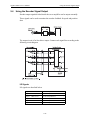
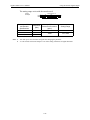
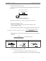
5.4 Using the Encoder Signal Output . . . . . . . . . . . . . . . . . . . . . . . . . . . . . . . . 5-26
5.5 Setting up the Reference Units . . . . . . . . . . . . . . . . . . . . . . . . . . . . . . . . . . 5-29
5.5.1 Electronic Gear Setting Examples . . . . . . . . . . . . . . . . . . . . . . . . . . . 5-31
5.5.2 Calculating Speed [x1000 Reference Units / min.] . . . . . . . . . . . . . . 5-32
5.5.3 Setting the Accel/ Decel Rate [x 1000 Reference Units/min/ms] . . . 5-33
5.6 Absolute Encoders . . . . . . . . . . . . . . . . . . . . . . . . . . . . . . . . . . . . . . . . . . . 5-35
5.6.1 Interface Circuit . . . . . . . . . . . . . . . . . . . . . . . . . . . . . . . . . . . . . . . . . 5-35
5.6.2 Configuring an Absolute Encoder . . . . . . . . . . . . . . . . . . . . . . . . . . . 5-35
5.6.3 Handling Batteries . . . . . . . . . . . . . . . . . . . . . . . . . . . . . . . . . . . . . . . 5-37
5.6.4 Absolute Encoder Setup. . . . . . . . . . . . . . . . . . . . . . . . . . . . . . . . . . . 5-37
5.6.5 Absolute Encoder Reception Sequence . . . . . . . . . . . . . . . . . . . . . . . 5-42
5.7 Program Table Mode (Mode 0) . . . . . . . . . . . . . . . . . . . . . . . . . . . . . . . . . 5-47
5.7.1 Program Table Mode Setting. . . . . . . . . . . . . . . . . . . . . . . . . . . . . . . 5-47
5.7.2 Program Operation Inputs Setting . . . . . . . . . . . . . . . . . . . . . . . . . . . 5-47
5.7.3 Program Step Selection . . . . . . . . . . . . . . . . . . . . . . . . . . . . . . . . . . . 5-48
5.7.4 Program (Index) Table Set-up . . . . . . . . . . . . . . . . . . . . . . . . . . . . . . 5-49
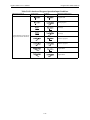
5.7.5 Event Condition Examples . . . . . . . . . . . . . . . . . . . . . . . . . . . . . . . . 5-53
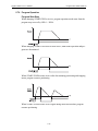
5.7.6 Program Operation. . . . . . . . . . . . . . . . . . . . . . . . . . . . . . . . . . . . . . . 5-54
5.7.7 Evaluation of Program Operation Input Conditions . . . . . . . . . . . . . 5-55
5.7.8 Minimum Input Signal Timing for Program Operation. . . . . . . . . . . 5-57
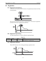
5.8 Registration . . . . . . . . . . . . . . . . . . . . . . . . . . . . . . . . . . . . . . . . . . . . . . . . . 5-58
5.8.1 Registration Specifications . . . . . . . . . . . . . . . . . . . . . . . . . . . . . . . . 5-58
5.8.2 Registration Input Setting . . . . . . . . . . . . . . . . . . . . . . . . . . . . . . . . . 5-58
5.8.3 Registration Operation . . . . . . . . . . . . . . . . . . . . . . . . . . . . . . . . . . . . 5-58
5.9 Zone Table Set-up. . . . . . . . . . . . . . . . . . . . . . . . . . . . . . . . . . . . . . . . . . . . 5-61
5.9.1 Zone Signal Conditions . . . . . . . . . . . . . . . . . . . . . . . . . . . . . . . . . . . 5-62
iv
Sigma II Indexer User’s Manual
Table of Contents
5.10 Program Table Examples . . . . . . . . . . . . . . . . . . . . . . . . . . . . . . . . . . . . .
5.11 Homing / Jog Speed Table Mode (Mode 1) . . . . . . . . . . . . . . . . . . . . . . .
5.11.1 Homing /Jog Mode Setting . . . . . . . . . . . . . . . . . . . . . . . . . . . . . . .
5.11.2 Homing / Jog Speed Table inputs Setting . . . . . . . . . . . . . . . . . . . .
5.11.3 Homing Routine Parameters . . . . . . . . . . . . . . . . . . . . . . . . . . . . . .
5.12 Homing Routine Operation. . . . . . . . . . . . . . . . . . . . . . . . . . . . . . . . . . . .
5.13 Jog Speed Table Operation . . . . . . . . . . . . . . . . . . . . . . . . . . . . . . . . . . . .
5.13.1 Jog Speed Table Example . . . . . . . . . . . . . . . . . . . . . . . . . . . . . . . .
5.13.2 Jog Speed Table Selection . . . . . . . . . . . . . . . . . . . . . . . . . . . . . . . .
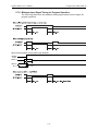
5.13.3 Jog Speed Table and Homing Operation Input Conditions . . . . . . .
5.13.4 Minimum Input Signal Timing for Homing and Jog Operation . . .
5-63
5-69
5-69
5-69
5-70
5-71
5-72
5-72
5-73
5-73
5-74
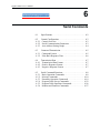
Chapter 6: Serial Commands . . . . . . . . . . . . . . . . . . . . . . . . . . . . . . . . . . . . . . . . . . . . . 6-1
6.1 Specifications (CN6). . . . . . . . . . . . . . . . . . . . . . . . . . . . . . . . . . . . . . . . . . . 6-2
6.2 Control Configuration. . . . . . . . . . . . . . . . . . . . . . . . . . . . . . . . . . . . . . . . . . 6-3
6.2.1 Control Overview . . . . . . . . . . . . . . . . . . . . . . . . . . . . . . . . . . . . . . . . 6-3
6.2.2 Serial Communication Parameters. . . . . . . . . . . . . . . . . . . . . . . . . . . . 6-3
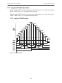
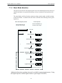
6.2.3 Axis Address Setting Graph . . . . . . . . . . . . . . . . . . . . . . . . . . . . . . . . 6-4
6.3 Command Transmission (Host Controller → Sigma II Indexer) . . . . . . . . . 6-5
6.3.1 Command Format . . . . . . . . . . . . . . . . . . . . . . . . . . . . . . . . . . . . . . . . 6-5
6.3.2 Echo Back Response Time . . . . . . . . . . . . . . . . . . . . . . . . . . . . . . . . . 6-6
6.4 Transmission Data (Sigma II Indexer → Host Controller). . . . . . . . . . . . . . 6-7
6.4.1 Transmission Data Format . . . . . . . . . . . . . . . . . . . . . . . . . . . . . . . . . 6-7
6.4.2 Positive Response Format . . . . . . . . . . . . . . . . . . . . . . . . . . . . . . . . . . 6-7
6.4.3 Negative Response Format . . . . . . . . . . . . . . . . . . . . . . . . . . . . . . . . . 6-7
6.5 Serial Command Functions. . . . . . . . . . . . . . . . . . . . . . . . . . . . . . . . . . . . . . 6-8
6.5.1 Basic Operation Commands . . . . . . . . . . . . . . . . . . . . . . . . . . . . . . . . 6-8
6.5.2 Moving Commands . . . . . . . . . . . . . . . . . . . . . . . . . . . . . . . . . . . . . . . 6-9
6.5.3 Parameter Operation Commands . . . . . . . . . . . . . . . . . . . . . . . . . . . . 6-19
6.5.4 Program Table Set-up Commands . . . . . . . . . . . . . . . . . . . . . . . . . . . 6-22
6.5.5 Program Table Operation Commands. . . . . . . . . . . . . . . . . . . . . . . . 6-26
6.5.6 Monitor and Function Commands . . . . . . . . . . . . . . . . . . . . . . . . . . . 6-27
Chapter 7: Using the Digital Operator . . . . . . . . . . . . . . . . . . . . . . . . . . . . . . . . . . . . . .
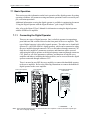
7.1 Basic Operation . . . . . . . . . . . . . . . . . . . . . . . . . . . . . . . . . . . . . . . . . . . . . .
7.1.1 Connecting the Digital Operator . . . . . . . . . . . . . . . . . . . . . . . . . . . . .
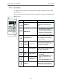
7.1.2 Functions . . . . . . . . . . . . . . . . . . . . . . . . . . . . . . . . . . . . . . . . . . . . . . .
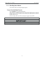
7.1.3 Resetting Servo Alarms . . . . . . . . . . . . . . . . . . . . . . . . . . . . . . . . . . . .
7.1.4 Basic Mode Selection . . . . . . . . . . . . . . . . . . . . . . . . . . . . . . . . . . . . .
7-1
7-2
7-2
7-3
7-5
7-6
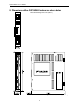
Chapter 8: Dimensional Drawings . . . . . . . . . . . . . . . . . . . . . . . . . . . . . . . . . . . . . . . . . 8-1
8.1 Dimensions of the JUSP-NS600 Indexer are shown below. . . . . . . . . . . . . 8-2
v
Sigma II Indexer User’s Manual
Table of Contents
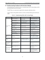
Chapter 9: Troubleshooting . . . . . . . . . . . . . . . . . . . . . . . . . . . . . . . . . . . . . . . . . . . . . . 9-1
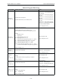
9.1 Troubleshooting Problems with No Alarm Display . . . . . . . . . . . . . . . . . . . 9-2
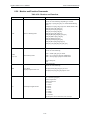
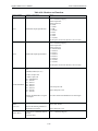
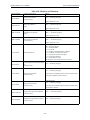
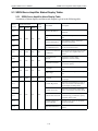
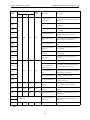
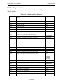
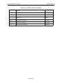
9.2 Sigma II Indexer Alarm/Error/Warning Status Display Table . . . . . . . . . . . 9-4
9.2.1 Sigma II Indexer Alarm Display Table . . . . . . . . . . . . . . . . . . . . . . . . 9-4
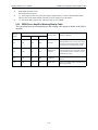
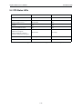
9.2.2 Sigma II Indexer Error/Warning Display Table . . . . . . . . . . . . . . . . . 9-7
9.3 SGDH Servo Amplifier Alarm Display Tables . . . . . . . . . . . . . . . . . . . . . 9-11
9.3.1 SGDH Servo Amplifier Alarm Display Table. . . . . . . . . . . . . . . . . . 9-11
9.3.2 SGDH Servo Amplifier Warning Display Table . . . . . . . . . . . . . . . . 9-13
9.4 STS Status LEDs . . . . . . . . . . . . . . . . . . . . . . . . . . . . . . . . . . . . . . . . . . . . 9-14
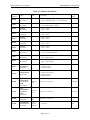
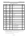
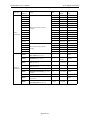
Appendix A: List of Parameters . . . . . . . . . . . . . . . . . . . . . . . . . . . . . . . . . . . . . . . . . . . A-1
A.1 JUSP-NS600 Indexer Parameters . . . . . . . . . . . . . . . . . . . . . . . . . . . . . . . . A-2
A.2 Servo Amplifier Parameters. . . . . . . . . . . . . . . . . . . . . . . . . . . . . . . . . . . . . A-6
A.3 Servo Amplifier Switches . . . . . . . . . . . . . . . . . . . . . . . . . . . . . . . . . . . . . A-10
Appendix B: Monitor Modes and Functions . . . . . . . . . . . . . . . . . . . . . . . . . . . . . . . . . B-1
B.1 Monitor Modes. . . . . . . . . . . . . . . . . . . . . . . . . . . . . . . . . . . . . . . . . . . . . . . B-2
B.2 Auxiliary Functions . . . . . . . . . . . . . . . . . . . . . . . . . . . . . . . . . . . . . . . . . . . B-4
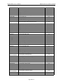
Appendix C: Serial Commands . . . . . . . . . . . . . . . . . . . . . . . . . . . . . . . . . . . . . . . . . . . C-1
C.1 Alphabetical List of Serial Commands . . . . . . . . . . . . . . . . . . . . . . . . . . . . C-2
Appendix D: Example Exercises . . . . . . . . . . . . . . . . . . . . . . . . . . . . . . . . . . . . . . . . . . D-1
D.1 Example Indexer Exercise #1 . . . . . . . . . . . . . . . . . . . . . . . . . . . . . . . . . . . D-2
D.2 Example Indexer Exercise #2 . . . . . . . . . . . . . . . . . . . . . . . . . . . . . . . . . . . D-5
D.3 Example Indexer Exercise #1 Solution . . . . . . . . . . . . . . . . . . . . . . . . . . . . D-6
D.4 Example Indexer Exercise #2 Solution . . . . . . . . . . . . . . . . . . . . . . . . . . . D-14
vi
Sigma II Indexer User’s Manual
Overview
Overview
Manual Outline
This manual provides the following information for the Sigma II Series SGMH/SGDH
servodrives with a JUSP-NS600 Indexer Application Module.
•
Procedures for installing and wiring the Sigma II Indexer Application Module.
•
Procedures for trial operation of the servodrive.
•
Specifications and methods for serial communications.
•
Procedures for setting parameters and program tables.
•
Procedures for digital I/O and serial mode operation.
•
Troubleshooting procedures.
Related Manuals
Refer to the following manuals as required.
Read this manual carefully to ensure the proper use of Sigma II Series servodrives. Also,
keep this manual in a safe place so that it can be referred to whenever necessary.
Manual Name
Manual Number
Sigma II Series Servo System
User’s Manual
YEA-S1A-S800-32.2
Sigma II Series Servo System
Product Catalog Supplement
G-M1#99001D
Contents
Describes the procedure used to select
Sigma II Series servodrives and capacities
and detailed information.
Describes the procedure used to select
Sigma II Series servodrives and capacities.
Refer to Sigma II User’s Manual for the following information.
•
Procedures for installing and wiring the servomotor and servo amplifier (encoder, motor
and power).
•
Procedures for using functions and adjusting the servodrives:
Selecting a regen resistor, special wiring, tuning and analog monitor.
•
Procedures for using the built-in panel operator and the hand-held digital operator.
•
Ratings and specifications for standard models.
vii
Sigma II Indexer User’s Manual
Using This Manual
Using This Manual
Intended Audience
This manual is intended for the following users.
• Those designing Sigma IΙ Series servodrive systems.
• Those installing or wiring Sigma IΙ Series servodrives.
• Those performing trial operation or adjustments of Sigma IΙ Series servodrives.
• Those maintaining or inspecting Sigma IΙ Series servodrives.
Description of Technical Terms
In this manual, the following terms are defined as follows:
• Servomotor = Sigma IΙ Series SGMAH/SGMPH/SGMGH/SGMSH servomotor.
• Servo Amplifier = Sigma IΙ Series SGDH servo amplifier.
• Servodrive = A set including a servomotor and servo amplifier.
• Servo System = A servo control system that includes the combination of a servodrive
with a host computer and peripheral devices.
Indication of Reverse Signals
In this manual, the names of reverse signals (ones that are valid when low) are written with
a forward slash (/) before the signal name, as shown in the following equations:
•
•
•
/S–ON = S–ON
/RGRT = RGRT
/START-STOP;/HOME = START-STOP; HOME (dual purpose input)
viii
Sigma II Indexer User’s Manual
Safety Precautions
Safety Precautions
The following precautions are for checking products upon delivery, installation, wiring,
operation, maintenance and inspections.
Checking Products upon Delivery
CAUTION
•
Always use the servomotor and servo amplifier in one of the specified combinations.
Not doing so may cause fire or malfunction.
Installation
CAUTION
•
Never use the products in an environment subject to water, corrosive gases,
inflammable gases, or combustibles.
Doing so may result in electric shock or fire.
Wiring
WARNING
•
•
Connect the ground terminal to a class 3 ground (100Ω or less).
Improper grounding may result in electric shock or fire.
Required for 7.5kW amplifiers: Use Yaskawa kit Number XXX for wiring the
power input and output terminals, or equivalent UL listed closed-loop ring terminals
designed to accept 4 AWG wires.
ix
Sigma II Indexer User’s Manual
Safety Precautions
CAUTION
•
•
Do not connect a three-phase power supply to the U, V, or W output terminals.
Doing so may result in injury or fire.
Securely fasten the power supply terminal screws and motor output terminal
screws.
Not doing so may result in fire.
Operation
CAUTION
•
Never touch any rotating motor parts while the motor is running.
Doing so may result in injury
CAUTION
•
•
•
•
Conduct trial operation on the servomotor alone with the motor shaft disconnected from machine to avoid any unexpected accidents.
Not doing so may result in injury.
Before starting operation with a machine connected, change the settings to
match the parameters of the machine.
Starting operation without matching the proper settings may cause the machine to
run out of control or malfunction.
Before starting operation with a machine connected, make sure that an emergency stop can be applied at any time.
Not doing so may result in injury.
Do not touch the heat sinks during operation.
Not doing so may result in burns due to high temperatures.
x
Sigma II Indexer User’s Manual
Safety Precautions
Maintenance and Inspection
WARNING
•
•
•
Do not remove the panel cover while the power is ON.
Doing so carries a risk of electric shock.
Do not touch terminals for five minutes after the power has been turned OFF.
Residual voltage may cause electric shock.
Never touch the inside of the servo amplifier.
Doing so may result in electric shock.
CAUTION
•
•
Do not disassemble the servomotor.
Doing so may result in electric shock or injury
Do not attempt to change wiring while the power is ON.
Doing so may result in electric shock or injury
General Precautions
Note the following to ensure safe application:
•
•
•
•
•
The drawings presented in this manual are sometimes shown without covers or
protective guards. Always replace the cover or protective guard as specified first,
and then operate the products in accordance with the manual.
The drawings presented in this manual are typical examples and may not
match the product you received.
This manual is subject to change due to product improvement, specification modification, and manual improvement. When this manual is revised, the manual code is
updated and the new manual is published as a next edition. The edition number
appears on the front and back covers.
If the manual must be ordered due to loss or damage, inform your nearest
Yaskawa representative or one of the offices listed on the back of this manual.
Yaskawa will not take responsibility for the results of unauthorized modifications of this product. Yaskawa shall not be liable for any damages or troubles
resulting from unauthorized modification.
xi
Sigma II Indexer User’s Manual
Safety Precautions
This page intentionally left blank.
xii
Sigma II Indexer User’s Manual
1
Checking Products and Part Names
This chapter describes the procedure for checking the
Sigma II Indexer application module upon delivery. It also
describes the name of product parts.
1.1
Introduction . . . . . . . . . . . . . . . . . . . . . . . . . . . . . . . . . . .1.2
1.2
Checking Products on Delivery . . . . . . . . . . . . . . . . . . . .1.3
1.2.1 External Appearance And Nameplate Examples . . . . . .1.3
1.3
Mounting the Sigma II Indexer Application Module
to a SGDH Servo Amplifier . . . . . . . . . . . . . . . . . . . . . . .1.6
1-1
Sigma II Indexer User’s Manual
1.1
Introduction
Introduction
The Sigma II Indexer application module (P/N JUSP-NS600) is a single-axis position controller with registration capabilities which connects to an SGDH servo amplifier via dualport RAM.
This combination expands the amplifier’s functionality to include simple point-to-point
positioning with an available registration function. The Sigma II Indexer option has two
operating modes, serial command mode and digital I/O mode.
The serial command mode allows immediate interpretation and execution of ASCII command strings sent via RS232/422/485 to the Sigma II Indexer. The digital I/O mode consists
of the program or index table (mode 0) and the jog speed table and homing (mode 1). While
in Mode the program table allows execution of stored index moves, selected with inputsignal patterns (binary format). While in Mode 1, the jog speed table allows execution of
stored jog speeds, selected with input-signal patterns (binary format).Three types of homing
routines are also available while in Mode 1.
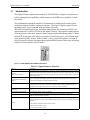
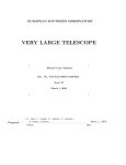
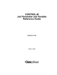
Figure 1.1 JUSP-NS600 Indexer/SGDH Combination
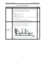
Table 1.1: Sigma II Indexer Functions
Function
Description
Digital I/O ModeProgram
(Index) Table (Mode 0)
Positioning data are selected from the program table stored in the indexer by using the positioning
data selection input signals (binary format). The indexer can store up to 128 program steps. All 128
program steps may be addressed with inputs.The program steps may be linked together to generate
more complex moves.
Digital I/O ModeJog Speed Table and Homing
(Mode 1)
Up to 16 jog speeds are available. Speeds are selected by using the jog selection input-signals
(binary format). Homing is available while in this mode.
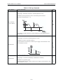
Serial Command Mode
Positioning data are input by ASCII command strings sent via RS232/RS422/RS485 to the indexer.
Commands can be sent up to 16 axes with one master controller. Positioning data can also be
selected from the program table stored in the indexer by ASCII commands.
Registration
Both serial command and program table mode support the registration function (external positioning).
Programmable Output Signals
5 programmable output signals are available.
Zone Signals
Up to 32 different zones can be defined to program the 5 programmable output signals
(/POUT0 - /POUT4) based on position.
Used for zero-point return (homing) when incremental encoder is used. Both serial command and
homing mode allow execution of the available homing routines. Three types of homing routines are
available:
Homing
1. Decel limit switch and encoder cø-pulse are used.
2. Only decel limit switch is used.
3. Only encoder cø-pulse is used.
1-2
Sigma II Indexer User’s Manual
1.2
Checking Products on Delivery
Checking Products on Delivery
The following procedure is used to check products upon delivery. Check the following
items when products are delivered.
Table 1.2:
Check items
Comments
Are the delivered products the ones
that were ordered?
Check the model numbers marked on the nameplates of the application
module.
Is there any damage?
Check the overall appearance, and check for damage or scratches that may
have occurred during shipping.
Can the application module be
Check the model number given on the SGDH servo amplifier nameplate. The
installed on the SGDH servo amplifier model number must contain “SGDH- FFF E” to support the Sigma II
used?
Indexer application module.
If any of the above items are faulty or incorrect, contact your Yaskawa sales representative
or the dealer from whom you purchased the products.
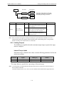
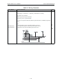
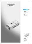
1.2.1 External Appearance And Nameplate Examples
Figure 1.2 External Appearance of Sigma II Indexer Application Module
Figure 1.3 Nameplate
1-3
Sigma II Indexer User’s Manual
Checking Products on Delivery
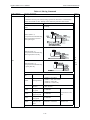
Figure 1.4 Block Diagram of Sigma II Indexer Functions.
Figure 1.5
Note: Refer to Table 1.3 for part numbers of items a-e.
1-4
Sigma II Indexer User’s Manual
Checking Products on Delivery
Table 1.3: Part Numbers
Indexer
Description
a
Item Number
Sigma II Indexer
JUSP-NS600
CN4 I/O Cable (with pigtail leads), 36 pin, 1.0m
CKI-NS600-01
CN4 I/O Cable (with pigtail leads), 36 pin, 2.0m
CKI-NS600-02
CN4 I/O Cable (with pigtail leads), 36 pin, 3.0m
CKI-NS600-03
CN4 I/O Cable (with terminal block)
JUSP-TA36P
CN1 I/O Cable (with pigtail leads), 50 pin, 1.0m
JZSP-CKI01-1(A)
CN1 I/O Cable (with pigtail leads), 50 pin, 2.0m
JZSP-CKI01-2(A)
CN1 I/O Cable (with pigtail leads), 50 pin, 3.0m
JZSP-CKI01-3(A)
CN1 I/O Cable (with terminal block)
JUSP-TA50P
I/O Cables
b
Serial
Cables
c
d
Software
Accessories
e
CN3, CN6, CN7 Serial Communication Cable (RS232 only),
YS-12
2.0m
CN6 Serial Communication Cable (with pigtail leads), 2.0m
YS-14
Hand-held Digital Operator Panel
JUSP-OP02A-1 + JZSP-CMSOO-1
CN3, CN6, CN7 Mating Connector
YSC-1
CN4 Mating Connector, 36 pin
DP9420007
CN1 Mating Connector, 50 pin
JZSP-CKI9
IndexWorks
Indexer Support Software
NS600-GUI
Note: See Sigma II Servo System Product Catalog Supplement for part numbers and additional information
on servo motors, servo amplifier, motor power cables, encoder cables and accessories.
1-5
Sigma II Indexer User’s Manual
1.3
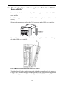
Mounting the Sigma II Indexer Application Module to an SGDH
Mounting the Sigma II Indexer Application Module to an SGDH
Servo Amplifier
This section describes how to mount a Sigma II Indexer application module on the SGDH
servo amplifier.
Use the following procedure to ensure the Sigma II Indexer application module is mounted
correctly.
1. Remove the connector cover from the CN10 connector on the SGDH servo amplifier.
2. Insert the lower two mounting notches into the mounting holes at the bottom of the right
side of the SGDH servo amplifier.
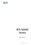
Figure 1.6 Mounting the JUSP-NS600 to an SGDH Servo Amplifier
3. Push the Sigma II Indexer application module in the direction indicated by the arrows in
the figure above, and insert the upper mounting notches of the Sigma II Indexer application
module into the upper mounting holes on the right side of the SGDH servo amplifier.
1-6
Sigma II Indexer User’s Manual
Mounting the Sigma II Indexer Application Module to an SGDH
4. For grounding, connect the ground wire of the Sigma II Indexer application module to the
point marked “G” on the SGDH servo amplifier. Refer to table 1.4 for the selection of the
proper screw size. Screws are provided with the application module.
Table 1.4: Sigma II Indexer Ground Wire Screw
Servo Amplifier
Screw
Note
SGDH-A3~02BE
SGDH-A3~10AE
M3x10
(round head phillips with split lock
washer and flat washer)
-
SGDH-15~50AE
SGDH-05~50DE
M4x10
(round head phillips with split lock
washer and flat washer)
-
SGDH-60~1EAE
SGDH-60~1EDE
M4x8
(round head phillips with split lock
washer and flat washer)
Use front panel side screw hole.
Figure 1.7
1-7
Sigma II Indexer User’s Manual
Mounting the Sigma II Indexer Application Module to an SGDH
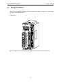
When the Sigma II Indexer application module has been mounted correctly, the SGDH
servo amplifier will appear as shown in the following diagram.
Figure 1.8
1-8
Sigma II Indexer User’s Manual
2
Installation
This chapter describes precautions for Sigma II Series and
Indexer application module installation.
The SGDH servo amplifiers are base-mounted units. Incorrect installation will cause problems. Always observe the
installation precautions shown in this chapter.
2.1
Storage Conditions . . . . . . . . . . . . . . . . . . . . . . . . . . . . . 2-2
2.2
Installation Site . . . . . . . . . . . . . . . . . . . . . . . . . . . . . . . 2-3
2.3
Orientation . . . . . . . . . . . . . . . . . . . . . . . . . . . . . . . . . . . 2-4
2.4
2.4.1
2.4.2
2.4.3
Installation . . . . . . . . . . . . . . . . . . . . . . . . . . . . . . . . . . .
Servo Amplifier Orientation . . . . . . . . . . . . . . . . . . . .
Cooling . . . . . . . . . . . . . . . . . . . . . . . . . . . . . . . . . . . . .
Side-by-side Installation . . . . . . . . . . . . . . . . . . . . . . .
2-1
2-5
2-5
2-5
2-5
Sigma II Indexer User’s Manual
2.1
Storage Conditions
Storage Conditions
Store the servo amplifier within the following temperature range, as long as it is stored with
the power cable disconnected.
-20 to 85°C
Figure 2.1 Sigma II Series Servo Amplifier with Sigma II Indexer Application Module Mounted
2-2
Sigma II Indexer User’s Manual
2.2
Installation Site
Installation Site
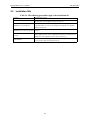
Table 2.1: The following precautions apply to the installation site.
Situation
Installation Precaution
Installation in a control panel
Design the control panel size, unit layout, and cooling method so the temperature around the servo amplifier does not exceed 55°C.
Installation near a heating unit
Minimize heat radiated from the heating unit as well as any temperature rise
caused by natural convection so the temperature around the servo amplifier
does not exceed 55°C.
Installation near a source of vibration
Install a vibration isolator beneath the servo amplifier to avoid subjecting it to
vibration.
Corrosive gas does not have an immediate effect on the servo amplifier, but
Installation at a site exposed to corrowill eventually cause electronic components and contactor - related devices to
sive gas
malfunction. Take appropriate action to avoid corrosive gas.
Other situations
Do not install the servo amplifier in hot and humid locations or locations subject to excessive dust or iron powder in the air.
2-3
Sigma II Indexer User’s Manual
2.3
Orientation
Orientation
Install the servo amplifier perpendicular to the panel wall as shown in the figure. The servo
amplifier must be oriented this way because it is designed to be cooled by natural convection or cooling fan.
Secure the servo amplifier using the mounting holes. The number of holes varies (from two
to four) with the frame size of the servo amplifier.
Wall
Ventilation
2-4
Sigma II Indexer User’s Manual
2.4
Installation
Installation
Follow the procedure below to install multiple servo amplifiers side by side in a control
panel.
2.4.1 Servo Amplifier Orientation
Install the servo amplifier perpendicular to the wall so the front panel containing connectors
faces outward.
2.4.2 Cooling
As shown in the figure above, allow sufficient space around each servo amplifier for cooling
by cooling fans or natural convection.
2.4.3 Side-by-side Installation
When installing servo amplifiers side by side as shown in the figure above, allow at least
0.39in. (10mm) between and at least 1.97in. (50mm) above and below each servo amplifier.
Install cooling fans above the servo amplifiers to avoid excessive temperature rise and to
maintain even temperature inside the control panel.
Environmental Conditions in the Control Panel
•
•
•
•
•
Ambient Temperature:0 to 55°C
Humidity:90% r.h., or less
Vibration: 0.5 G (4.9 m/s2)
Condensation and Freezing:None
Ambient Temperature for Long-term Reliability:45°C maximum
2-5
Sigma II Indexer User’s Manual
Installation
This page intentionally left blank.
2-6
Sigma II Indexer User’s Manual
3
Connectors
3.1
I/O Signals (CN1, CN4) . . . . . . . . . . . . . . . . . . . . . . . . .
3.1.1 Connection Example of I/O Signal
Connector (CN1, CN4)3-23
3.1.2 I/O Signals Connector (CN1, CN4) . . . . . . . . . . . . . . .
3.1.3 I/O Signal Names and Functions . . . . . . . . . . . . . . . . .
3.1.4 Interface Circuits. . . . . . . . . . . . . . . . . . . . . . . . . . . . . .
3.2
Serial Communication Connectors (CN6, CN7) . . . . .
3.2.1 Single Axis System Example (CN6, CN7). . . . . . . . .
3.2.2 Multi-Axis System Example (CN6 only) . . . . . . . . . .
3.2.3 Communication Specifications (CN6, CN7) . . . . . . .
3.2.4 Communication Connectors (CN6, CN7). . . . . . . . . .
3.2.5 Connector Signal Names (CN6,CN7). . . . . . . . . . . . .
3.2.6 Connection Examples . . . . . . . . . . . . . . . . . . . . . . . . .
3.3
3-2
3-4
3-6
3-7
3-10
3-10
3-10
3-11
3-11
3-13
3-14
Sigma II Indexer Power Loss . . . . . . . . . . . . . . . . . . . . 3-17
3-1
Sigma II Indexer User’s Manual
3.1
I/O Signals (CN1, CN4)
I/O Signals (CN1, CN4)
The section describes I/O signals for the SGDH Servo Amplifier and Sigma II Indexer
application module.
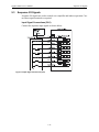
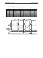
3.1.1 Connection Example of I/O Signal Connector (CN1, CN4)
*
*
and error)
42
43
44
46
/SEL5
41
/SEL6
45
Program Step Select 5
(Enabled when ON)
Program Step Select 6
(Enabled when ON)
tuning
* For SGDH-
DE
type servo amplifiers,
replace LIC with 24V and L2C with OV.
Figure 3.1 SGDH I/O (CN1)
3-2
Sigma II Indexer User’s Manual
I/O Signals (CN1, CN4)
CNIO Dual Port RAM
(ON when in-position)
Programmable
Outputs
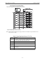
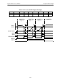
Figure 3.2 Sigma II Indexer JUSP-NS600 I/O (CN4)
Note: Mode 0 enables input functions /START-STOP, /PGMRES, /SEL0, /SEL1, /SEL2, /SEL3, /SEL4.
Mode 1 enables input functions /HOME, /JOGP, /JOGN, /JOG0, /JOG1, /JOG2, /JOG3.
3-3
Sigma II Indexer User’s Manual
I/O Signals (CN1, CN4)
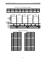
3.1.2 I/O Signals Connector (CN1, CN4)
The following diagrams show the layout of CN1 and CN4 terminals.
Table 3.1: CN1 Terminal Layout (Servo Amplifier)
1
2
SG
-
27
SG
-
31
SG
33
-
35
-
37
-
39
-
41
/PCO
43
BAT (-)
PG Divided
Output
C-Phase
-
47
-
49
/SEL6
Program
select 6
+24VIN
External
power supply input
Servo warning output
/PSO
30
/S-RDY-
Servo Ready
Output
32
ALM-
Servo alarm
output
34
/PAO
PG Divided
Output
A-Phase
36
/PBO
PG Divided
Output
B-Phase
38
AL02
Alarm code
output
40
/S-ON
Servo ON
input
42
P-OT
Forward
drive prohibited input
44
/DEC
Zero point
return deceleration LS
input
46
/RGRT
Registration
latch
48
PSO
S-Phase
Signal
Output
50
-
-
Reverse run
prohibited
input
-
/WARN+
N-OT
Brake interlock output
Program
select 5
Battery (+)
Battery (-)
25
Note 1.
2.
BAT (+)
/SEL5
PG Divided
Output
C-Phase
45
23
24
PCO
Alarm code
output
(opencollector
output)
-
-
21
22
-
AL03
/BK-
PG Divided
Output
B-Phase
-
-
19
20
-
AL01
-
-
17
18
-
PBO
28
PG Divided
Output
A-Phase
-
-
15
16
-
PAO
Servo warning output
Servo alarm
output
-
Signal
Ground
13
14
-
ALM+
/WARN-
Servo ready
output
-
-
11
12
-
/S-RDY+
26
Brake interlock output
-
Signal
Ground
9
10
-
/BK+
29
7
8
-
5
6
Signal
Ground
Signal
Ground
3
4
SG
S-Phase
Signal
Output
Do not use unused terminals for relays.
Connect the shield of the I/O signal cable to the connector shell.
The shield is connected to the FG (frame ground) at the servo amplifier-end connector.
3-4
Sigma II Indexer User’s Manual
I/O Signals (CN1, CN4)
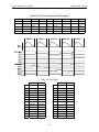
Table 3.2: CN4 Terminal Layout (Sigma II Indexer)
1
24V/COM
External
input power
supply
19
2
3
/MODE 0/1
21
/STARTSTOP;
/HOME
Start-Stop/
Home input
/PGMRES;
/JOGP
Program
reset/Jog
forward
input
9
/SEL0;
/JOGN
8
11
13
15
17
/SEL2;
/JOG1
/SEL3;
/JOG2
/SEL4;
/JOG3
-
Program
select 1/Jog
select 0
input
27
Program
select 2/Jog
select 1
input
Program
select 3/Jog
select 2
input
Program
select 4/Jog
select 3
input
-
-
-
18
-
-
Programmable
Output 0
24
/POUT1-
Programmable
Output 1
26
/POUT2-
Programmable
Output 2
28
/POUT3-
Programmable
Output 3
30
/POUT4-
Programmable
Output 4
32
-
-
34
-
-
36
-
-
-
-
-
-
35
/POUT0-
Programmable
Output 4
-
33
16
/POUT4+
22
Programmable
Output 3
-
31
14
/POUT3+
In-position
output
Programmable
Output 2
29
12
/POUT2+
/INPOSITION-
Programmable
Output 1
-
Program
select 0/Jog
reverse input
-
/POUT1+
20
Programmable
Output 0
25
10
/SEL1;
/JOG0
-
/POUT0+
23
6
7
-
In-position
output
-
Mode select
input
4
5
-
/INPOSITION+
-
-
-
Table 3.3: CN1 Specifications (Servo Amplifier)
Specifications for
Servo Amplifier
Receptacle
Applicable Mating Connector
Connector
10250–52A2JL or
Equivalent 50–pin 10150–3000VE
Right Angle
Receptacle
Case
10350–52A0–008
Note: Yaskawa P/N JZSP-CKI9 includes 3M connector and case.
3-5
Manufacturer
Sumitomo 3M Co.
Sigma II Indexer User’s Manual
I/O Signals (CN1, CN4)
Table 3.4: CN4 Specifications (Sigma II Indexer)
Specifications for
Servo Amplifier
Receptacle
Applicable Mating Connector
Connector
10236–52A25L or
Equivalent 36–pin 10136–3000VE
Right Angle
Receptacle
Case
10336–52A0–008
Manufacturer
Sumitomo 3M Co.
Note: Yaskawa P/N DP9420007 includes 3M connector and case.
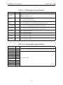
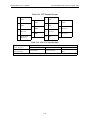
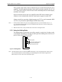
3.1.3 I/O Signal Names and Functions
The following section describes servo amplifier I/O signal names and functions.
Table 3.5: CN1 Input Signals (Servo Amplifier)
Signal Name Pin No.
/S-ON
40
/SEL5
41
P-OT
N-OT
42
43
/DEC
44
/SEL6
45
/RGRT
46
+24VIN
47
BAT (+)
BAT (-)
21
22
Function
Servo ON: Turns ON the servomotor when the gate block in the inverter is released.
Mode 0: Program select input 5.
Mode 1: No effect.
Forward run prohibit
Overtravel prohibited: Stops Servo motor when movable
Reverse run prohibit
part travels beyond the allowable range of motion
Zero point return deceleration limit switch:
Deceleration LS used when the motor returns to the zero point during homing.
Mode 0: Program select input 6.
Mode 1: No effect.
Registration latch signal: used for external positioning.
Control power supply input for sequence signals: User must provide the +24-V power
supply.
Minimum operating voltage: 11V
Maximum operating voltage: 25V
Connecting pin for the absolute encoder backup battery
Connect to either CN8 or CN1-21,22.
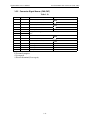
Table 3.6: CN1 Output Signals (Servo Amplifier)
Signal Name
ALM+
ALM/WARN+
/WARN/BK+
/BK/S-RDY+
/S-RDYALO1
ALO2
ALO3
Pin No.
31
32
25
26
27
28
29
30
37
38
39 (1)
FG
Shell
Function
Servo alarm: Turns OFF when an alarm is detected.
Servo Warning: ON when an error or warning is detected.
Brake interlock: Output that controls the brake.
The brake is released when this signal is ON.
Servo ready. ON if there is no servo alarm when
the control/main circuit power supply is turned ON.
Alarm code output: Outputs 3-bit alarm codes
Open-collector: 30 V and 20 mA rating maximum
Connected to frame ground if the shield wire of the
I/O signal cable is connected to the connector shell.
Note 1. Pin numbers in parenthesis () indicate signal grounds.
3-6
Sigma II Indexer User’s Manual
I/O Signals (CN1, CN4)
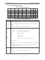
Table 3.7: CN4 Input Signals (Sigma II Indexer)
Signal Name
Pin No.
Function
+24V/COM
1
Control power supply input for sequence signals. User must provide the +24V power supply.
Minimum operating voltage: 11V
Maximum operating voltage: 25V
/Mode 0/1
3
Switches between Mode 0 and Mode 1.
Mode 0: Index table mode when ON.
Mode 1: Jog and homing mode when OFF.
/START-STOP;
/HOME
5
Mode 0: Starts selected index table program when ON. Stops program operation when OFF.
Mode 1: Starts homing routine when ON. Stops homing routing when OFF.
/PGMRES;/JOGP 7
Mode 0: Resets index table program when OFF →ΟΝ.
Mode 1: Forward jog enabled when ON. Stops forward jog when OFF
/SEL0;/JOGN
9
Mode 0: Program select input 0
Mode 1: Reverse jog enabled when ON. Stops reverse jog when OFF.
/SEL1;/JOG0
11
Mode 0: Program select input 1
Mode 1: Jog speed select input 0
/SEL2;/JOG1
13
Mode 0: Program select input 2
Mode 1: Jog speed select input 1
/SEL3;/JOG2
15
Mode 0: Program select input 3
Mode 1: Jog speed selected input 2
/SEL4;/JOG3
17
Mode 0: Program select input 4
Mode 1: Jog speed select input 3
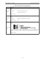
Table 3.8: CN4 Output Signals (Sigma II Indexer)
Signal Name
Pin No.
Functions
/INPOSITION +
19
/INPOSITION -
20
In-position: Turns ON when the position error is within the inposition window setting. Pn821
and when the commanded position profile has ended (also known as DEN, distribution end).
/POUT 0+
21
/POUT0-
22
/POUT1+
23
/POUT1-
24
/POUT2+
25
/POUT2-
26
/POUT3+
27
/POUT3-
28
/POUT4+
29
/POUT4-
30
Programmable Outputs
3-7
Sigma II Indexer User’s Manual
I/O Signals (CN1, CN4)
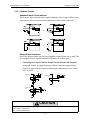
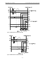
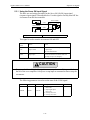
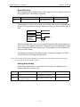
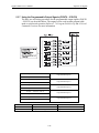
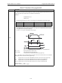
3.1.4 Interface Circuits
Sequence Input Circuit Interface
The sequence input circuit interface connects through a relay or open-collector transistor circuit. Select a low-current relay otherwise a faulty contact will result.
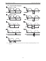
Output Circuit Interfaces
Any of the following three types of servo amplifier output circuits can be used. Connect an input circuit at the host controller following one of these types.
•
Connecting to an Open-Collector Output Circuit (Alarm Code Outputs)
Alarm code signals are output from open-collector transistor output circuits.
Connect an open-collector output circuit through a photocoupler, relay, or line
receiver circuit.
VDC
VDC
Photocoupler
IDC
Servo amplifier
end
Relay
Servo amplifier
end
P
0V
0V
0V
VDC
Servo amplifier
end
IDC
P
0V
0V
CAUTION
The maximum allowable voltage and current capacities for open-collector circuits are:
• VDC, Voltage: 30VDC max.
• IDC, Current: 20mADC max.
3-8
Sigma II Indexer User’s Manual
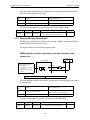
•
I/O Signals (CN1, CN4)
Connecting to a Photocoupler Output Circuit
Photocoupler output circuits are used for SGDH servo amplifier alarm, servo
ready, holding brake, warning, and all Sigma II Indexer outputs.
Connect a photocoupler output circuit through a relay or line receiver circuit.
VDC
VDC
IDC
IDC
CAUTION
The maximum allowable capacities for photocoupler output circuits are:
• VDC, Voltage: 30VDC max.
• IDC, Current: 50mADC max.
3-9
Sigma II Indexer User’s Manual
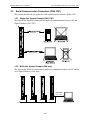
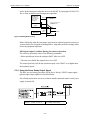
Serial Communication Connectors (CN6, CN7)
This section describes the wiring for the serial communication connectors (CN6, CN7)
3.2.1 Single Axis System Example (CN6, CN7)
The figure below illustrates connection for single-axis communication between a PC and
Sigma II Indexer (CN6, CN7)
RS232/422
RS232/422/485
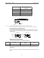
3.2.2 Multi-Axis System Example (CN6 only)
The figure below illustrates connection for multi-axis communication between a PC and up
to 16 Sigma II Indexers (CN6 only)
NS600
NS600
NS600
S
T
S
S
T
S
C
N
7
C
N
7
C
N
7
C
N
7
789 A
BCD
C
N
4
0 12
3456
C
N
6
A
D
R
S
EF
C
N
4
BCD
0 12
3456
3456
C
N
6
A
D
R
S
EF
C
N
4
BCD
0 12
0 12
A
D
R
S
789 A
S
T
S
789 A
S
T
S
EF
BCD
EF
789 A
NS600
3456
3.2
Serial Communication Connectors (CN6, CN7)
A
D
R
S
C
N
4
C
N
6
C
N
6
Serial Command
Communication
RS422 / RS485
Notebook PC
Up to 16 axes total
3-10
Sigma II Indexer User’s Manual
Serial Communication Connectors (CN6, CN7)
3.2.3 Communication Specifications (CN6, CN7)
The following table shows the communications specifications for CN6 and CN7.
Table 3.9: Communication Specifications
Item
Interface
Transmission Range
Baud Rate
Port
Specification
CN6
RS232/RS422/RS485
CN7
RS232/RS422
CN6
CN7
RS232: 3m maximum
RS422/RS485: 50m maximum
CN6
9.6, 19.2, 38.4 Kbaud
CN7
9.6 Kbaud
Synchronization Type
CN6
Asynchronous (start-stop synchronization)
Transmission Format
CN6
CN7
Start: 1 bit
Data: 7 bit, ASCII code
Parity: 1 bit, Even
Stop: 1 bit
X On/X Off Control
CN6
CN7
None
Shift Control
CN6
CN7
None
Communication
CN6
CN7
Half-duplex
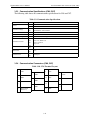
3.2.4 Communication Connectors (CN6, CN7)
Table 3.10: CN6 Terminal Layout
1
TXD
8
2
3
/TXD
RXD
RXD
/RXD
5
11
12
6
7
9
10
4
TXD
RT (Terminal
Resistance)
/RXD
13
14
3-11
GND
/TXD
Sigma II Indexer User’s Manual
Serial Communication Connectors (CN6, CN7)
.
Table 3.11: CN7 Terminal Layout
1
TXD
8
2
3
5
10
12
14
/TXD
11
Reserved
13
Reserved
Reserved
/RXD
RT (Terminal
Resistance)
9
RXD
/RXD
Reserved
6
7
/TXD
RXD
4
TXD
GND
Table 3.12: CN6, CN7 Specifications
Specifications for Sigma II
Indexer Receptacle
10214-52A2JL 14-Pin
Right Angle Plug
Applicable Mating Connectors
Connector
Case
Manufacturer
10114-3000VE
10314-52AO-008
Sumitomo
3M Co.
Note: Yaskawa P/N YSC-1 includes 3M case and connector.
3-12
Sigma II Indexer User’s Manual
Serial Communication Connectors (CN6, CN7)
3.2.5 Connector Signal Names (CN6,CN7)
Table 3.13:
Pin No.
Signal name
Signal Circuit Name
Signal Direction
1
TXD
Transmit data (not inverted)
2
/TXD
Transmit data (inverted)
3
RXD
Receive data (not inverted)
4
/RXD
Receive data (inverted)
5
Reserved
Reserved pin
6
/RXD
7
RT
Short pins 6 and 7 apply an internal 220 Ω terminating resistance between RXD and /
RXD.
8
TXD
Transmit data (not inverted)
9
/TXD
Transmit data (inverted)
10
RXD
Receive data (not inverted)
11
Reserved
Reserved pin
#
12
Reserved
Reserved pin
#
13
Reserved
Reserved pin
-
14
GND
Signal ground: 0 V
-
-
P: Personal computer
S: Servopack
#: Reserved terminal (leave open).
3-13
Sigma II Indexer User’s Manual
Serial Communication Connectors (CN6, CN7)
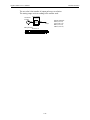
3.2.6 Connection Examples
PC (RS232 port)
Figure 3.3 RS232C Single-Axis Communication (CN6, CN7)
RT
Figure 3.4 RS422 Single-Axis Communication (CN6, CN7)
3-14
Sigma II Indexer User’s Manual
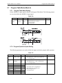
Serial Communication Connectors (CN6, CN7)
FG
Figure 3.5 RS422 Multi-Axis Communication (CN6)
Figure 3.6 RS485 Multi-Axis Communication (CN6)
3-15
Sigma II Indexer User’s Manual
Serial Communication Connectors (CN6, CN7)
RS422/485 Interface Cable
1. Make sure that the drive system, control system, power system, and other transmission
systems are separate from each other (i.e., do not run the power wire with the control
wire).
2. The RS422/485 cable length is 50 m maximum. Use the minimum length necessary.
3. The Sigma II Indexer module RS422/485 interface is a non-isolated system. Errors
may occur from noise in the connected terminal. If noise occurs use a shield-type cable
and/or ferrite core to reduce the noise.
4. In the case of RS422, insert a terminating resistor (100Ω) as needed. Make the termination on the PC side receiving line. Short pins 6 and 7 only on the last axis.
5. In the case of RS485, attach a terminating resistor (100Ω) to the PC side transmission
line. Short pins 6 and 7 only on the last axis.
6. If noise persists in the case of RS422 or RS485, it may be necessary to add pull-up/
pull-down resistors as shown in Fig. 3.5 and 3.6.
3-16
Sigma II Indexer User’s Manual
3.3
Sigma II Indexer Power Loss
Sigma II Indexer Power Loss
See the Sigma II Series Servo System User’s Manual (3.3.4 Servo Amplifier Power Losses)
for information on servo amplifier power losses at rated output.
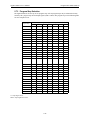
Table 3.14: Sigma II Indexer Specifications
Item
Specification
Minimum operating voltage
5.05V min.
Maximum operating voltage
5.25V max.
Maximum operating current
500 mA max.
Maximum power loss
2.6 W max.
Note: Power to the Sigma II Indexer Application Module (JUSP-NS600) is supplied by the SGDH servo
amplifier.
3-17
Sigma II Indexer User’s Manual
Sigma II Indexer Power Loss
This page intentionally left blank.
3-18
Sigma II Indexer User’s Manual
4
Trial Operation
This chapter describes a two-step trial operation. Be sure to complete step 1 before proceeding to step 2.
4.1
Two-Step Trial Operation . . . . . . . . . . . . . . . . . . . . . . . 4-2
4.1.2 Step 1: Trial Operation for Servomotor without Load . 4-3
4.1.3 Step 2: Trial Operation with the Servomotor
Connected to the Machine . . . . . . . . . . . . . . . . . . . . . . 4-8
4-1
Sigma II Indexer User’s Manual
4.1
Two-Step Trial Operation
Two-Step Trial Operation
Make sure that all wiring is completed prior to starting trial operation.
Perform the trial operation in the order given below (step 1 and 2) for your safety. See 4.1.1
and 4.1.2 for more details on the trial operation.
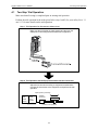
Step 1: Trial Operation for Servomotor without Load
Make sure the servomotor is wired properly and then turn the
shaft prior to connecting the servomotor to the equipment.
YASKAWA
SERVOPACK
SGDM-
MODE/SET
200V
DATA/
CHARGE POWER
L1
L2
C
N
3
1
2
L1C
L2C
C
N
1
B1
B2
U
V
W
C
N
2
Check wiring.
Do not connect to the equipment.
Step 2: Trial Operation with the Equipment and Servomotor Connected
Adjust the servomotor according to equipment characteristics.
Connect the servomotor to the equipment, and perform the trial
operation.
Adjust speed by autotuning.
JUSPNS600
Indexer
SGDH
servo
amplifier
SGMH
servomotor
Connect to the equipment.
4-2
Sigma II Indexer User’s Manual
Two-Step Trial Operation
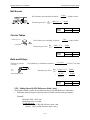
4.1.1 Step 1: Trial Operation for Servomotor without Load
CAUTION
• Do not operate the servomotor while it is connected to the equipment.
To prevent accidents, initially perform step 1 where the trial operation is conducted under no-load conditions
(with all couplings and belts disconnected).
In step 1, make sure that the servomotor is wired properly as shown below. Incorrect
wiring is generally the reason why servomotors fail to operate properly during trial
operation.
z Check main power supply circuit wiring.
z Check servomotor wiring.
z Check CN1 and CN4 I/O signal wiring (if applicable).
z Check CN6 serial command wiring (if applicable).
Make sure the host device and other adjustments are completed as much as possible
in step 1 (prior to connecting the servomotor to equipment).
4-3
Sigma II Indexer User’s Manual
Two-Step Trial Operation
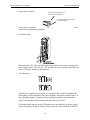
1. Secure the servomotor.
Secure the mounting plate of the
servomotor to the equipment.
Do not connect anything to the sha
(no-load conditions).
Secure the servomotor mounting plate to the equipment in order to prevent the servomotor from moving during operation.
2. Check the wiring.
Disconnect the CN1, CN4, and CN6 connectors and check servomotor wiring in the
power supply circuit. The CN1 I/O, CN4 I/O and CN6 serial command signals are not
used, so leave the connectors disconnected.
3. Turn ON power.
Turn ON servo amplifier power. If the servo amplifier has turned ON normally, the
LED display on the front panel of the servo amplifier will appear as shown above. It
may take approximately 3 minutes before any display appears on the front panel.
Power is not supplied to the servomotor because the servo is OFF.
If an alarm display appears on the LED indicator as shown above, the power supply
circuit, servomotor wiring, or encoder wiring is incorrect. The STS status LED will
4-4
Sigma II Indexer User’s Manual
Two-Step Trial Operation
also appear in red immediately at power-up if an alarm occurs. In this case, turn OFF
power and take appropriate action. See 8 Troubleshooting.
Note If an absolute encoder is used, it must be set up. Refer to 5.6.4 Absolute Encoder Setup.
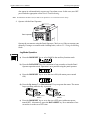
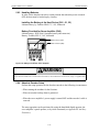
4. Operate with the Panel Operator.
Panel operator
{
Operate the servomotor using the Panel Operator. Check to see if the servomotor runs
normally. If using a servomotor with a holding brake, refer to 5.3.3 Using the Holding
Brake.
Jog Mode Operation
200V
YASKAWA
SERVOPACK
SGDM-
a) Press the MODE/SET key to select Fn002 in the auxiliary function mode.
MODE/SET
DATA/
CHARGE
POWER
b) Press the DATA/SHIFT key for a minimum of one second to select the Panel
Operator operation mode. Operation is now possible using the panel operator.
c) Press the MODE/SET key to set to the servo ON (with motor power turned
ON).
d) Press the Up Arrow or Down Arrow key to operate the motor. The motor
keeps operating while the key is pressed.
Motor Forward
Rotation
Motor Reverse
Rotation
e) Press the MODE/SET key to set to the servo OFF state (with motor power
turned OFF). Alternatively, press the DATA/SHIFT key for a minimum of one
second to set to the servo OFF state.
4-5
Sigma II Indexer User’s Manual
Two-Step Trial Operation
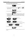
f) Press the DATA/SHIFT key for a minimum of one second, and the display will
revert to Fn002 in the auxiliary function mode.
This ends operation under panel operator control.
The motor speed for operation under digital operator control can be changed with
parameter:
Parameter
Pn304
Setting
(rpm)
Signal
Jog Speed
Default Setting: 500
Note: The rotation direction of the servomotor depends on the setting of parameter Pn000.0 “Rotation
Direction.” The above example shows a case where Pn000.0 is set to “0” as a default setting.
5. Connect the signal lines.
Use the following procedure to connect the CN1, CN4, and/or CN6 connectors.
a) Turn OFF power.
b) Connect the CN1, CN4 and/or CN6 connector.
c) Turn ON power again.
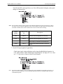
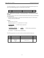
6. Check the CN1 input signals (if applicable).
Check input signal wiring in Monitor Mode using the panel operator. Select monitor
Un005 SGDH Input Signal Monitor. See Sigma II User’s Manual 7.1.7 Operation in
Monitor Mode for more details on the procedure.
4-6
Sigma II Indexer User’s Manual
Two-Step Trial Operation
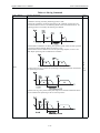
Turn ON and OFF each signal line to see if the LED monitor bit display on the panel
changes as shown below.
/SEL5
/SEL6
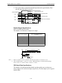
Note: The servomotor will not operate properly if the following signal lines are not wired correctly. Always
wire them correctly. Short the signal lines if they will be unused. The input signal selections (parameters Pn803 to Pn80F) can be used to eliminate the need for external short circuiting.
Signal
Symbol
Connector Pin
No.
P-OT
CN1-42
The servomotor can rotate in the forward
direction when this signal line is low (0V).
N-OT
CN1-43
The servomotor can rotate in the reverse
direction when this signal line is low (0V).
/S-ON
CN1-40
The servomotor is turned ON when this signal
line is low (0V). Leave the servomotor OFF.
+24VIN
CN1-47
Control power supply terminal for sequence
signals.
Description
7. Check CN4 input signals (if applicable)
Check input signal wiring in Monitor mode using a handheld digital operator via
CN7. Select monitor Un801 NS600 Input Signal Monitor. See Sigma II User’s Manual 7.1.7 Operation in Monitor Mode for more details.
Note: CN1 and CN4 input signals can also be monitored by serial commands, IN1 and IN2, respectively, via
CN6. See 6 Serial Commands for serial communication specifications, command format, and serial
command descriptions.
4-7
Sigma II Indexer User’s Manual
Two-Step Trial Operation
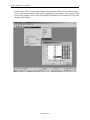
8. Check CN6 Serial Command Port (if applicable)
Establish serial communication using either the Indexer software or terminal emulator. Refer to 6 Serial Commands for serial communication specifications, command
format, and serial command descriptions for more details when using a terminal
emulator or similar device.
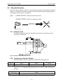
9. Turn ON the servo.
Servo amplifier
Servomotor
/S-ON
CN1-40
0V
Turns ON the servo.
Turn ON the servo ON signal.
Display with the servo ON.
Set /S-ON (CN1-40) to 0V. If normal, the servomotor will turn ON and the LED
indicator on the front panel will display as shown above. If an alarm display
appears, take appropriate action as described in 8 Troubleshooting.
Note: Serial command, SVON can also be used to turn on the servo.
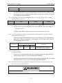
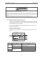
4.1.2 Step 2: Trial Operation with the Servomotor Connected to the Machine
WARNING
Follow the procedure below for step 2 operation precisely as given.
Malfunctions that occur after the servomotor is connected to the equipment not only
damage the equipment, but may also cause an accident resulting in death or injury.
Before proceeding to step 2, repeat step 1 (servomotor trial operation without a load)
until all concerns including parameters and wiring have fully satisfied expectations.
After step 1 has been completed, proceed to step 2 for trial operation with the servomotor connected to the equipment. The servo amplifier is now adjusted in the following ways to meet the specific equipment’s characteristics.
4-8
Sigma II Indexer User’s Manual
Two-Step Trial Operation
•
Using autotuning to match the servo amplifier to the equipment’s characteristics.
•
Matching the direction of rotation and speed to the equipment’s specifications.
•
Checking the final control form.
JUSPNS600
Indexer
SGDH
servo
amplifier
Servomotor
Connect to the machine.
Follow the procedures below to perform the trial operation.
1. Make sure power is OFF.
2. Connect the servomotor to the equipment.
See Sigma II User’s Manual 2.1 Servomotors for more details on connecting the
servomotor.
3. Use autotuning to match the servo amplifier to equipment characteristics.
See Sigma II User’s Manual 6.3 Autotuning.
4. Operate the servomotor by digital I/O or serial mode operation. See 5 Parameter
Settings and Functions and 6 Serial Commands for more information.
5. Set and record user settings.
Set parameters as required and record all settings for use later in maintenance.
Note: The servomotor will not be broken in completely during the trial operation. Therefore, let the system
run for a sufficient amount of time after the trial operation has been completed to ensure that it is
properly broken in.
4-9
Sigma II Indexer User’s Manual
Two-Step Trial Operation
This page intentionally left blank.
4-10
Sigma II Indexer User’s Manual
5
Parameter Settings and Functions
5.1
Parameter Limits with Sigma II Indexer. . . . . . . . . . . . . 5-4
5.2
Settings According to Device Characteristics . . . . . . . . 5-6
5.2.1 Switching Servomotor Rotation Direction . . . . . . . . . . 5-6
5.2.2 Setting the Overtravel Limit Function . . . . . . . . . . . . . 5-7
5.2.3 Limiting Torques. . . . . . . . . . . . . . . . . . . . . . . . . . . . . 5-11
5.3
Sequence I/O Signals . . . . . . . . . . . . . . . . . . . . . . . . . .
5.3.1 Using the Servo ON Input Signal . . . . . . . . . . . . . . . .
5.3.2 Using Servo Alarm and Alarm Code Outputs . . . . . .
5.3.3 Using the Holding Brake . . . . . . . . . . . . . . . . . . . . . .
5.3.4 Using the Servo Ready Output Signal . . . . . . . . . . . .
5.3.5 Using the Warning Output Signal . . . . . . . . . . . . . . . .
5.3.6 Using the /INPOSITION Output Signal . . . . . . . . . . .
5.3.7 Using the Programmable Output Signals
(/POUT0 ~ /POUT4). . . . . . . . . . . . . . . . . . . . . . . . . .
5.4
5-12
5-15
5-16
5-17
5-20
5-21
5-23
5-24
Using the Encoder Signal Output . . . . . . . . . . . . . . . . . 5-26
5.5
Setting up the Reference Units . . . . . . . . . . . . . . . . . . .
5.5.1 Electronic Gear Setting Examples . . . . . . . . . . . . . . .
5.5.2 Calculating Speed . . . . . . . . . . . . . . . . . . . . . . . . . . . .
5.5.3 Calculating Acceleration / Deceleration . . . . . . . . . .
5-29
5-31
5-32
5-33
5.6
Absolute Encoders . . . . . . . . . . . . . . . . . . . . . . . . . . . .
5.6.1 Interface Circuit . . . . . . . . . . . . . . . . . . . . . . . . . . . . .
5.6.2 Configuring an Absolute Encoder . . . . . . . . . . . . . . .
5.6.3 Handling Batteries . . . . . . . . . . . . . . . . . . . . . . . . . . .
5.6.4 Absolute Encoder Setup . . . . . . . . . . . . . . . . . . . . . . .
5.6.5 Absolute Encoder Reception Sequence . . . . . . . . . . .
5-35
5-35
5-35
5-37
5-37
5-42
5.7
Program Table Mode (Mode 0). . . . . . . . . . . . . . . . . . .
5.7.1 Program Table Mode Setting . . . . . . . . . . . . . . . . . . .
5.7.2 Program Operation Inputs Setting . . . . . . . . . . . . . . .
5.7.3 Program Step Selection. . . . . . . . . . . . . . . . . . . . . . . .
5.7.4 Program (Index) Table Set-up. . . . . . . . . . . . . . . . . . .
5.7.5 Event Condition Examples . . . . . . . . . . . . . . . . . . . . .
5.7.6 Program Operation . . . . . . . . . . . . . . . . . . . . . . . . . . .
5-47
5-47
5-47
5-48
5-49
5-53
5-53
5-1
Sigma II Indexer User’s Manual
5.7.7
5.7.8
5.8
5.8.1
5.8.2
5.8.3
Evaluation of Program Operation Input Conditions . . 5-55
Minimum Input Signal Timing
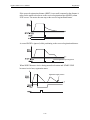
for Program Operation . . . . . . . . . . . . . . . . . . . . . . . . . 5-57
Registration. . . . . . . . . . . . . . . . . . . . . . . . . . . . . . . . . .
Registration Specifications . . . . . . . . . . . . . . . . . . . . .
Registration Input Setting . . . . . . . . . . . . . . . . . . . . . .
Registration Operation. . . . . . . . . . . . . . . . . . . . . . . . .
5-58
5-58
5-58
5-58
5.9
Zone Table Set-up . . . . . . . . . . . . . . . . . . . . . . . . . . . . . 5-61
5.9.1 Zone Signal Conditions . . . . . . . . . . . . . . . . . . . . . . . . 5-62
5.10
Program Table Examples . . . . . . . . . . . . . . . . . . . . . . . 5-63
5.11 Homing / Jog Speed Table Mode (Mode 1) . . . . . . . . .
5.11.1 Homing /Jog Mode Setting . . . . . . . . . . . . . . . . . . . . .
5.11.2 Homing / Jog Speed Table inputs Setting . . . . . . . . . .
5.11.3 Homing Routine Parameters . . . . . . . . . . . . . . . . . . . .
5.12
5-69
5-69
5-69
5-70
Homing Routine Operation. . . . . . . . . . . . . . . . . . . . . . 5-71
5.13
5.13.1
5.13.2
5.13.3
Jog Speed Table Operation . . . . . . . . . . . . . . . . . . . . .
JOG Speed Table Example . . . . . . . . . . . . . . . . . . . . .
Jog Speed Table Selection . . . . . . . . . . . . . . . . . . . . .
Jog Speed Table and Homing Operation
Input Conditions . . . . . . . . . . . . . . . . . . . . . . . . . . . . .
5.13.4 Minimum Input Signal Timing for Homing
and Jog Operation . . . . . . . . . . . . . . . . . . . . . . . . . . . .
5-2
5-72
5-72
5-73
5-73
5-74
Sigma II Indexer User’s Manual
Before Reading this Chapter
This chapter describes the use of each CN1 and CN4 I/O signal for the SGDH Servo amplifier with the Sigma II Indexer. It also describes the procedure for setting the related parameters for the intended purposes.
The following sections can be used as references for this chapter.
• CN1 and CN4 I/O signal list: Refer to 3.1.3 I/O Signal Names and Functions.
• CN1 and CN4 I/O signal terminal layout: Refer to 3.1.2 I/O Signals Connector (CNI,
CN4) Terminal Layout
• Parameter list: Refer to Appendix A List of Parameters
The CN1 and CN4 connector is used to exchange signals with external circuits.
Parameter Configurations
Parameters are comprised of the types shown in the following table. Refer to Appendix A
List of Parameters.
Table 5.1: Parameter Configurations
Type
Parameter No.
Description
Function Selection
Parameters
Pn000 to Pn005
Pn819
Select basic and application functions such as the type of function
or the stop mode used when an alarm occurs.
Servo Gain and Other
Parameters
Pn100 to Pn123
Set numerical values such as speed and position loop gains.
Position Parameters
Pn200 to Pn208
Set position parameters such as the position reference movement averaging time.
Speed Parameters
Pn308
Set speed parameters such as the speed feed forward filter time constant.
Torque Parameters
Pn401 to Pn409
Set torque parameters such as the forward/reverse torque limits.
Sequence Parameters
Pn500 to Pn509
Pn803 to Pn818
Pn833 to Pn834
Set output conditions for sequence signals and flexible I/O signal configuration.
Motion Parameters
Pn81A to Pn828
Set motion parameters, such as the zero point return direction.
Others
Pn600 to Pn601
Specify the capacity for an external regenerative resistor.
Serial Communication
Parameters
Pn800 to Pn802
Set parameters for serial command communication settings.
Auxiliary Function Exe- Fn000 to Fn014
cution
Fn800 to Fn808
Monitor Modes
Un000 to Un00D
Un800 to Un811
Execute auxiliary functions such as JOG Mode operation
Enable speed, torque, I/O and position monitoring.
5-3
Sigma II Indexer User’s Manual
5.1
Parameter Limits with Sigma II Indexer
Parameter Limits with Sigma II Indexer
This section explains the limits for parameters and standard settings with the Sigma II
Indexer mounted.
Parameter Limits
When the Sigma II Indexer application module is mounted on a SGDH servo amplifier, the
following parameters are automatically set. The following parameters will be treated as
“reserved for system use,” so do not change them. The SGDH servo amplifier will be set for
position control. It is not necessary to set parameters for speed and torque control, so do not
change the settings.
Table 5.2: List of Parameters for System Use with the JUSP-NS600
Parameter
Pn000
Pn002
Digit
Parameter Name
Set Value
Contents/Description
1
Control Method
1
Position Control
2
Axis Address
(ADRS)
Copies ADRS setting on rotary switch of JUSP-NS600
0
T-REF Allocation (Torque
Limit / Torque Feed-Forward)
0
Not used
3
Full Closed Loop Usage
0
Not available
Pn004
1
Reserved
0
Not used
Pn005
0
BK Control
0
Not used. SGDH controls /BK.
Pn200
2
Clear Operation
0
Clears position error when servo is off
0
Position Reference Filter
Selection
1
Average Movement Filter
1
Position Control Option
(V-REF as Speed Forward
0
Not used
0
Input Signal Mapping
1
Input Signal Mapping
1
/S-ON Mapping
8
NS600 monitors SIO as /S-ON
2
/P-CON Mapping
8
NS600 monitors SI1 as /SEL5
3
/P-OT Mapping
8
NS600 monitors SI2 as P-OT
0
/N-OT Mapping
8
NS600 monitors SI3 as N-OT
1
/ALM-RST Mapping
8
NS600 monitors SI4 as /DEC
2
/P-CL Mapping
8
NS600 monitors SI5 as /SEL6
3
/N-CL Mapping
8
NS600 monitors SI6 as /RGRT
0
/SPD-D Mapping
8
Not used
1
/SPD-A Mapping
8
Not used
2
/SPD-B Mapping
8
Not used
3
/C-SEL Mapping
8
Not used
0
/Z-CLAMP Mapping
8
Not used
1
/INHIBIT Mapping
8
Not used
2
/G-SEL Mapping
8
Not used
3
Reserved Mapping
8
Not used
0
/COIN
0
Not used
1
/V-CMP
0
Not used
2
/TGON
0
Not used
3
/S-RDY
3
Fixed at S03
Pn207
Pn50A
Pn50B
Pn50C
Pn50D
Pn50E
5-4
Sigma II Indexer User’s Manual
Parameter Limits with Sigma II Indexer
Table 5.2: List of Parameters for System Use with the JUSP-NS600
Parameter
Pn50F
Pn510
Pn512
Digit
Parameter Name
Set Value
Contents/Description
0
/CLT
0
Not used
1
/VLT
0
Not used
2
/BK
2
Fixed at S02
3
/WARN
1
Fixed at S01
0
/NEAR
0
Not used
1
Reserved
0
Not used
2
Not used
0
Not used
3
Not used
0
Not used
0
S01 Reverse
-
Equivalent to setting in Pn816
1
S02 Reverse
-
Equivalent to setting in Pn817
2
S03 Reverse
-
Equivalent to setting in Pn818
3
Not Used
0
Not used
These parameters are set automatically the first time the power to the servo amplifier is turned ON after the
Sigma II Indexer has been mounted. Startup will take approximately 2 seconds when these parameters are
being set.
5-5
Sigma II Indexer User’s Manual
5.2
Settings According to Device Characteristics
Settings According to Device Characteristics
This section describes the procedure for setting parameters according to the dimensions and
performance of the equipment used.
5.2.1 Switching Servomotor Rotation Direction
The servo amplifier has a Reverse Rotation Mode that reverses the direction of servomotor rotation without rewiring. Forward rotation in the standard setting is
defined as counterclockwise as viewed from the load.
With the Reverse Rotation Mode, the direction of servomotor rotation can be
reversed without changing other parameters. Only the direction (+, ) of shaft
motion is reversed.
Standard Setting
Reverse Rotation Mode
Forward Reference
Reverse Reference
PBO (Phase B)
PBO (Phase B)
Setting Reverse Rotation Mode
Use the parameter Pn000.0.
Parameter
Pn000.0
Signal
Setting
Direction Selection
Default Setting: 0
Use the following settings to select the direction of servomotor rotation.
Setting
Description
0
Forward rotation is defined as counterclockwise
(CCW) rotation as viewed from the load.
(Standard setting)
1
Forward rotation is defined as clockwise (CW)
rotation as viewed from the load.
(Reverse Rotation Mode)
5-6
Sigma II Indexer User’s Manual
Settings According to Device Characteristics
5.2.2 Setting the Overtravel Limit Function
The overtravel limit function forces movable equipment parts to stop if they exceed
the allowable range of motion.
Using the Hardware Overtravel Function
To use the hardware overtravel function, connect the overtravel limit switch input
signal terminals shown below to the correct pins of the servo amplifier CN1 connector.
Input o P-OT CN1-42
Forward Run Prohibited
(Forward Overtravel)
Input o N-OT CN1-43
Reverse Run Prohibited
(Reverse Overtravel)
Connect limit switches as shown below to prevent damage to the devices during linear motion.
Reverse rotation end
Servomotor
Forward rotation end
Limit
switch
Limit
switch
Servo Amplifier
P-OT
N-OT
CN1-42
CN1-43
Figure 5.1 Hardware Overtravels
Drive status with an overtravel input signal (P-OT, N-OT) ON or OFF is shown in
the following table. These are the default settings.
Signal
P-OT
N-OT
State
Description
ON= Input signal closed
Forward rotation allowed, (normal operation status).
OFF=Input signal open
Forward run prohibited (reverse rotation allowed).
ON= Input signal closed
Reverse rotation allowed, (normal operation status).
OFF=Input signal open
Reverse run prohibited (forward rotation allowed).
5-7
Sigma II Indexer User’s Manual
Settings According to Device Characteristics
Set the following parameters to specify whether or not the input signals are used for
overtravels. The factory setting is that the input signals are used for overtravels.
Parameter
Pn80C
Pn80D
Signal
P-OT
N-OT
Pin No.
Setting
Default
CN1-42
0 = Input Signal Open = OT Status, Forward Run Prohibited
1 = Input Signal Closed = OT Status, Forward Run Prohibited
2 = Always OT Status, Forward Run Prohibited
3 = Forward Run Always Allowed
0
CN1-43
0 = Input Signal Open = OT Status, Reverse Run Prohibited
1 = Input Signal Closed = OT Status, Reverse Run Prohibited
2 = Always OT Status, Reverse Run Prohibited
3 = Reverse Run Always Allowed
0
OV
Figure 5.2 Hardware Overtravel Short-Circuiting
Using the Software Position Limits
Set the following parameters to specify the software position limits.
Parameter
Name
Unit
-
Setting
Default
0 = Linear
1 = Rotary (Shortest Path)
2 = Rotary (Forward Rotation)
3 = Rotary (Reverse Rotation)
0
Pn81A
Moving Method
Pn81B
Position Reference
Forward Limit
Reference
Unit
- 99999999 ~ + 99999999
+99999999
Pn81C
Position Reference
Reverse Limit
Reference
Unit
-99999999 ~ + 99999999
-99999999
Moving Method Settings
1. Pn81A=0=Linear:
An error will occur if commanded position is beyond forward or reverse position reference limits. Motor will not move. If motor reaches the software limits while jogging,
motor will decelerate to a stop at the deceleration rate set in Pn820. Disable the software limits by setting both the forward and reverse position reference limits to 0.
The software limits are ignored until homing is complete when a homing routine is
specified for an incremental encoder. Refer to 5.11.3 Homing Routine Parameters for
more information regarding homing.
2. Pn81A=1=Rotary (Shortest Path): Used for rotary motion.
Absolute move commands rotate in the direction of the shortest path of travel.
5-8
Sigma II Indexer User’s Manual
Settings According to Device Characteristics
The forward and reverse position reference limits are used to set the roll-over position.
When rotating in the forward direction, the position reference rolls over to the reverse
position limit after reaching the forward position limit. When rotating in the reverse
direction, the position reference rolls over to the forward position limit after reaching
the reverse position limit.
Pn81D is the home position. Alarm, E16A, will occur if Pn81D is outside the position reference limits (Pn81D>|Pn81B, Pn81C|) when pn81A=1, 2, or 3.
3. Pn81A=2=Rotary (Forward): Used for rotary motion.
Absolute move commands rotate in the forward direction only.
The forward and reverse position reference limits are used to set the roll-over position
(same as Pn81A=1).
4. Pn81A=3=Rotary (Reverse): Used for rotary motion.
Absolute move commands rotate in the reverse direction only.
The forward and reverse position reference limits are used to set the roll-over position
(same as Pn81A=1).
Servomotor Stop Mode for Hardware Overtravels (P-OT and N-OT)
Set the following parameters to specify the Servomotor Stop Mode when P-OT and N-OT
input signals are used.
Specify the Servomotor Stop Mode when either of the following signals are input during
servomotor operation.
•
•
Forward run prohibited input (P-OT,CN1-42)
Reverse run prohibited input (N-OT,CN1-43)
5-9
Sigma II Indexer User’s Manual
Parameter
Pn819
Settings According to Device Characteristics
Parameter
Signal
Setting
Pn819
Overtravel Stop Mode
Default Setting: 0
Signal
Overtravel Stop Mode
Setting
Description
0
Stops the servomotor the same way as turning the servo OFF (according to Pn001.0). Servo is in baseblock after stopping.
1
Decelerates the servomotor immediately to a stop and puts the servomotor in servo lock.
2
Decelerates the servomotor to a stop at the preset deceleration and
puts the servomotor in servo lock.
Deceleration setting: Pn820 deceleration parameter
Parameter
Signal
Setting (x1000 ref. units/min/msec)
Default
Pn820
Deceleration
Range: 1 to 99999999
1000
Servo OFF Stop Mode Selection
The SGDH servo amplifier turns OFF under the following conditions:
• Servo ON input signal (/S-ON, CN1-40) is turned OFF.
• Servo alarm occurs.
• Power is turned OFF.
Specify the Stop Mode if any of these occur during operation.
Parameter
Signal
Setting
Pn001.0
Servo OFF or
Alarm Stop Mode
Default Setting: 0
5-10
Sigma II Indexer User’s Manual
Servo
OFF
Settings According to Device Characteristics
Stop Mode
Pn001.0 = 0
or 1
After stopping
0
Hold with
dynamic brake
Stop by dynamic
brake
1 Coast status
Pn001.0 = 2
Parameter
Pn001.0
Coast to a stop
Signal
Servo OFF or
Alarm Stop Mode
The dynamic brake stops the servomotor
electrically by shorting the motor windings
and diverting the energy to a resistor.
Coast status
Setting
Description
Default
0
Uses the dynamic brake to stop the servomotor, and maintains dynamic brake status
after stopping.
1
Uses the dynamic brake to stop the servomotor, and cancels dynamic brake status
after stopping to go into coast status.
2
Coasts the servomotor to a stop. The servomotor is turned OFF and stops due to
equipment friction.
0
Note: If the Servomotor is stopped or rotating at extremely low speed when the items above are set at 0
(dynamic brake status after stopping with the dynamic brake), then braking power is not generated
and the servomotor will stop the same as in coast status.
5.2.3 Limiting Torques
The SGDH servo amplifier limits the maximum output torque to protect the equipment or workplace.
Internal Torque Limits
Maximum torque is limited to the values set in the following parameters for forward
and reverse rotation.
Parameter
Signal
Setting (%)
Default
Pn402
Forward Torque Limit
Range: 0 to 800
800
Pn403
Reverse Torque Limit
Range: 0 to 800
800
The torque limits are specified as a percentage of the rated torque.
Note: 1) If torque limit is set higher than the maximum torque of the servomotor, the maximum torque of
the servomotor is the limit.
2) External Torque Limits (/P-CL, /N-CL) are not available on the SGDH with the Sigma II Indexer.
5-11
Sigma II Indexer User’s Manual
5.3
Sequence I/O Signals
Sequence I/O Signals
Sequence I/O signals are used to control servo amplifier and indexer operation. Connect these signal terminals as required.
Input Signal Connections (CN1)
Connect the sequence input signals as shown below.
/SEL5
/SEL6
Figure 5.3 Input Signal Connections (CN1)
5-12
Sigma II Indexer User’s Manual
Sequence I/O Signals
Input Signal Connections (CN4)
Connect the sequence input signals as shown below.
Ω
Figure 5.4 Input Signal Connections (CN4)
Note: Provide a separate external I/O power supply; neither the servo amplifier or Sigma II Indexer have an
internal 24V power supply.
Table 5.3: Input Signal Specifications (CN1, CN4)
Item
Inputs
Specification
CN1: /S-ON, /SEL5, P-OT, N-OT, /DEC, /SEL6, /RGRT
CN4: /MODE0/1, /START-STOP;/HOME, /PGMRES;/JOGP, /SEL0;/JOGN,
/SEL1;/JOG0, /SEL2;/JOG1, /SEL3;/JOG2, /SEL4;/JOG3
Input Format Sinking or Sourcing
Isolation
Optical
Voltage
11 to 25 VDC
Input Imped3.3 k:
ance
Current
8 mA maximum
Rating (ON)
OFF Current 0.1 mA maximum (OFF Voltage = 1.0 V)
5-13
Sigma II Indexer User’s Manual
Sequence I/O Signals
Output Signal Connections (CN1)
Connect the sequence output signals as shown in the following figure.
Figure 5.5 Output Signal Connections (CN1)
Output Signal Connections (CN4)
Connect the sequence output signals as shown in the following figure.
Figure 5.6 Output Signal Connections (CN4)
Note: Provide a separate external I/O power supply; neither the servo amplifier or the Sigma II Indexer have
an internal 24V power supply.
5-14
Sigma II Indexer User’s Manual
Sequence I/O Signals
5.3.1 Using the Servo ON Input Signal
The basic use and wiring procedure for the Servo ON (/S-ON) input signal
(sequence input signal) is described below. Use this signal to forcibly turn OFF the
servomotor from the host controller.
Servo amplifier
I/O power supply
+24V
+24VIN
CN1-47
3.3k:
/S-ON
CN1-40
7mA
Photo
coupler
Host controller
0V
o Input /S-ON CN1-40
Servo ON
This signal is used to turn the servomotor ON and OFF.
CN1-40
State
Status
Result
ON
Input Closed
Turns ON the servomotor: operates according
to signal input.
This is the default state.
OFF
Input Open
Servomotor cannot operate.
Do not turn OFF the servomotor while it is
operating except in an emergency.
CAUTION
Do not use the Servo ON (/S-ON) signal to start or stop the motor. Doing so will shorten
the life of the servo amplifier. Always use a stop input or command to start or stop the
servomotor.
The following parameter is used to set the state of the /S-ON signal.
Parameter
Pn80B
Signal
/S-ON
Pin No.
Setting
Default
CN1-40
0 = Input Signal Closed
= Servo ON
1 = Input Signal Open
= Servo ON
2 = Always Servo ON
3 = Always Servo OFF
0
5-15
Sigma II Indexer User’s Manual
Sequence I/O Signals
5.3.2 Using Servo Alarm and Alarm Code Outputs
The basic procedure for connecting alarm output signals is described below.
I/O power supply
Servo amplifier
+24V
Photocoupler
Photocoupler output levels
per output node:
• Maximum operating voltage: 30VDC
• Maximum output current:
50mADC
CN1-31
1
50mA max.
CN1-32
ALM+
CN1-37
ALO1
0V
ALM-
20mA max.
Open-collector output levels per output node:
• Maximum operating
voltage: 30VDC
• Maximum output current: 20mADC
CN1-38
ALO2
CN1-39
ALO3
CN1-1
SG
0V
0V
Host controller
A suitable external I/O power supply must be provided by the user separately
because there is no internal 24V power supply in the servo amplifier.
The use of the photocoupler output signals is described below.
Output o ALM+ CN1-31
Servo Alarm Output
Output o ALM- CN1-32
Signal Ground for Servo Alarm Output
These alarms are output when a servo amplifier alarm is detected.
Servo amplifier
Alarm
detection
ALM output
Turns
Turnspower
powerOFF.
OFF
Form an external circuit so this alarm output (ALM) turns the servo amplifier OFF.
State
Status
Result
ON
Circuit between CN1-31 and 32 is closed, and CN1-31 is at low level.
Normal state.
OFF
Circuit between CN1-31 and 32 is open, and CN1-31 is at high level.
Alarm state.
Alarm codes ALO1, ALO2 and ALO3 are output to indicate each alarm type.
The uses of open-collector output signals ALO1, ALO2 and ALO3 is described
below.
Output o ALO1 CN1-37
Alarm Code Output
Output o ALO2 CN1-38
Alarm Code Output
Output o ALO3 CN1-39
Alarm Code Output
Output o SG CN1-1
Signal Ground for Alarm Code Output
5-16
Sigma II Indexer User’s Manual
Sequence I/O Signals
These signals output alarm codes to indicate the type of alarm detected by the servo
amplifier. Use these signals to display alarm codes at the host controller. See 8.2.1&
8.3.1 Alarm Status Display Table for more on the relationship between alarm display
and alarm code output.
Form an external circuit so the servo amplifier turns OFF when an alarm occurs.
Alarms are reset automatically when the control power supply is turned OFF.
Alarms can also be reset using a digital operator via CN7, by serial command ARES
via CN6, or by the built-in panel display (SGDH alarms only).
Note: 1.
2.
Encoder alarms cannot always be reset by digital operator or by serial command. See 8.2.1 &
8.3.1 Alarm Status Display Table for list of resettable alarms. In that case, turn the control power
supply OFF to reset the alarm.
When an alarm occurs, always eliminate the cause before resetting the alarm.
5.3.3 Using the Holding Brake
The holding brake is used when a servodrive controls a vertical axis. In other words,
a servomotor with brake prevents the movable part from shifting due to the force of
gravity when system power goes OFF.
Servomotor
Holding brake
Prevents the movable part from
shifting due to gravity when
system power goes OFF.
Figure 5.7 Holding Brake
Note: The brake built into the servomotor SGM
H with brakes is a de–energization brake, which is used
only to hold and cannot be used for braking. Use the holding brake only to hold a stopped motor.
Brake torque is at least 120% of the rated motor torque.
5-17
Sigma II Indexer User’s Manual
Sequence I/O Signals
Wiring Example
Use the servo amplifier output signal /BK and the brake power supply to form a
brake ON/OFF circuit. The following diagram shows a standard wiring example.
Servomotor
with brake
Servo amplifier
Power supply
L1
L2
L3
L1C
L2C
CN1-27
27
BK-RY
A (1)
U
B (2)
V
D (4)
E (5)
F (6)
/BK+
+24V
M
C (3)
W
BK
CN1-28
/BK-
PG
CN2
BK-RY
Blue or
yellow
White
Red
AC
DC
Black
Brake Power Supply
Figure 5.8 Wiring Example
Output o /BK
Brake Interlock Output
This output signal controls the brake when using a servomotor with a brake and does
not have to be connected when using a servomotor without a brake.
State
Status
Result (default state)
ON:
Output Closed or low level
Releases the brake.
OFF:
Output Open or high level
Applies the brake.
The following parameter is used to set the state of /BK output.
Parameter
Signal
Pin No.
Setting
Default
Pn817
/BK
CN1-27, 28
0 = Output Closed = Releases the brake.
1 = Output Open = Releases the brake.
0
Related Parameters
Parameter
Description
Pn506
Time Delay from Brake Reference until Servo OFF
Pn507
Speed Level for Brake Reference Output during Motor Operation
Pn508
Timing for Brake Reference Output during Motor Operation
5-18
Sigma II Indexer User’s Manual
Sequence I/O Signals
Brake ON Timing
If the equipment moves slightly due to gravity when the brake is applied, set the following parameter to adjust brake ON timing.
Parameter
Signal
Setting (10ms)
Default
Pn506
Brake Reference Servo OFF Delay
Time
Setting Range: 0 to 50
0
This parameter is used to set the output time from the brake control signal /BK until
the servo OFF operation (servomotor output stop) when a servomotor with a brake is
used.
/S-ON input
(CN1-40)
Servo ON
Servo OFF
Release brake
Hold with brake
/BK output
Servo ON/OFF
operation
(Servomotor
ON/OFF status)
Servomotor
ON
Servomotor OFF
Servo OFF
time delay
With the standard setting, the servo is turned OFF when the /BK signal (brake operation) is active. The equipment may move slightly due to gravity depending on equipment configuration and brake characteristics. If this happens, use this parameter to
delay servo OFF timing.
This setting sets the brake ON timing when the servomotor is stopped. Use Pn507
and 508 for brake ON timing during operation.
Note: The servomotor will turn OFF immediately if an alarm occurs. The equipment may move due to gravity in the time it takes for the brake to operate.
Holding Brake Setting
Set the following parameters to adjust brake ON timing so the holding brake is
applied when the servomotor stops.
Parameter
Signal
Setting
Default
Pn507
Brake Reference Output Speed
Level
Setting Range: 0 to 10000rpm
100
Pn508
Timing for Brake Reference Output
during Motor Operation
Setting Range: 0 to 100 x 10ms
50
5-19
Sigma II Indexer User’s Manual
Sequence I/O Signals
Set the brake timing used when the servo is turned OFF by input signal /S-ON (CN140) or when an alarm occurs during motor operation.
/S-ON input
Power OFF by
/S-ON (CN1-40)
input or alarm
occurrence
Servo ON
Servo OFF
Stop by dynamic brake
or coast to a stop.
(Pn001.0)
Motor speed
(rpm)
Pn-507
/BK output
Release
brake
Hold with brake
Pn508
Figure 5.9 Holding Brake Setting
Brake ON timing when the servomotor stops must be adjusted properly because servomotor brakes are designed as holding brakes. Adjust the parameter settings while
observing equipment operation.
/BK Signal Output Conditions During Servomotor Operation
The circuit is open under either of the following conditions:
• Motor speed drops below the setting at Pn507 after servo OFF.
• The time set at Pn508 has elapsed since servo OFF.
The actual speed used will be the maximum speed even if Pn507 is set higher than
the maximum speed.
5.3.4 Using the Servo Ready Output Signal
The basic use and wiring procedures for the Servo Ready (/S-RDY) output signal
(photocoupler output signal) are described below.
Servo Ready means there are no servo alarms and the main and control circuit power
supply is turned ON.
Output o /S-RDY CN1-29, 30
Servo Ready Output Signal
5-20
Sigma II Indexer User’s Manual
Sequence I/O Signals
This signal indicates that the servo amplifier has completed all preparations and is
ready to receive the Servo ON signal.
/S-RDY
State
Status
Result (default state)
ON
Output Closed or low level.
Servomotor is ready.
OFF
Output Open or high level.
Servomotor is not ready.
The following parameter is used to set the state of the /S-RDY output.
Parameter
Pn818
Signal
/S-RDY
Pin No.
Setting
Default
CN1-29, 30
0 = Output Closed = Servo ready.
1 = Output Open = Servo ready.
0
5.3.5 Using the Warning Output Signal
The basic use and wiring procedure for the warning (/WARN) output signal (photocoupler output signal) are given below.
The signal consists of the following output signals.
/WARN signals: overload, regenerative overload, low battery, and
indexer error
I/O power supply
+24V
Servo amplifier
Photocoupler output levels
per output node:
• Maximum operating voltage: 30VDC
• Maximum output current:
50mADC
0V
CN1-25 /WARN+
CN1-26 /WARN-
Output o /WARN CN1-25, 26
Warning Output Signal
This output signal indicates an overload, regenerative overload warning, low battery,
or indexer error.
/WARN
State
Status
Result (default state)
ON
Output Closed or low level.
Error warning. (overload, regenerative overload, low battery, and indexer error).
OFF
Output Open or high level.
Normal operation. No warning.
The following parameter is used to set the state of /WARN output.
Parameter
Pn816
Signal
/WARN
Pin No.
Setting
Default
CN1-25, 26
0 = Output Closed = Error Warning.
1 = Output Open = Error Warning.
0
5-21
Sigma II Indexer User’s Manual
Sequence I/O Signals
The following parameter is used to output warning details (overload, regenerative
overload, and low battery only) with an alarm code.
Parameter
Signal
Setting
Pn001.3
Warning Code Output Selection
Default Setting: 0
Pn001.3
Setting
Result
0
Outputs alarm codes alone for alarm codes ALO1,
ALO2 and ALO3.
1
Outputs both alarm and warning codes for alarm
codes ALO1, ALO2 and ALO3 and outputs an
alarm code when an alarm occurs.
The following warning codes are output in 3 bits.
Warning Indication
Warning Code Output
Warning Description
ALO1
ALO2
ALO3
A.91
ON signal
(low level)
OFF signal
(high level)
OFF signal
(high level)
Overload
A.92
OFF signal
(high level)
ON signal
(low level)
OFF signal
(high level)
Regenerative overload
A.93
ON signal
(low level)
ON signal
(low level)
OFF signal
(high level)
Low Battery
5-22
Sigma II Indexer User’s Manual
Sequence I/O Signals
5.3.6 Using the /INPOSITION Output Signal
The basic use and wiring procedure for the positioning completed (/INPOSITION)
output signal (photocoupler output signal) is described below. The signal is output to
indicate that servomotor operation is completed.
Output o /INPOSITION CN4-19,20
Positioning Completed Output Signal
This signal indicates that servomotor movement has been completed. The /INPOSITION output signal turns ON when the position error is within the inposition window width, Pn821, and when the position distribution ends (DEN). The Indexer
continuously outputs position commands while positioning, similar to a pulse train.
This is known as a “distribution”. Therefore, the /INPOSITION output signal does
not turn on while the distribution continues.
INPOSITION
State
Status
Result (default state)
ON
Circuit between CN4–19 and 20 is
closed.
Positioning is completed. (Position error is
below the setting.)
OFF
Circuit between CN4–19 and 20 is
open.
Positioning is not completed. (Position
error is above the setting.)
The following parameter is used to set the number of error pulses.
Parameter
Signal
Setting
(reference units)
Default
Pn821
/INPOSITION Width
Setting Range: 1 to 99999
1
Set the number of error pulses in reference units.
The /INPOSITION width setting has no effect on final positioning accuracy.
5-23
Sigma II Indexer User’s Manual
Sequence I/O Signals
5.3.7 Using the Programmable Output Signals (/POUT0 ~ /POUT4)
The basic use and wiring procedures for the programmable output signals (/POUT0
~ /POUT4) are described below. The outputs can be used in either program table
mode or serial mode operation. Refer to 5.7.4 Program Table Set-Up and 6.5 Serial
Command Functions for more information.
Output o /POUT0+ CN4-21
Programmable Output 0
Output o /POUT0- CN4-22
Output o /POUT1+ CN4-23
Programmable Output 1
Output o /POUT1- CN4-24
Output o /POUT2+ CN4-25
Programmable Output 2
Output o /POUT2- CN4-26
Output o /POUT3+ CN4-27
Programmable Output 3
Output o /POUT3- CN4-28
Output o /POUT4+ CN4-29
Programmable Output 4
Output o /POUT4- CN4-30
/POUT0 ~ /POUT4 State
State
Result (default state)
ON
Output Closed or Low Level
Output Active
OFF
Output Closed or High Level
Output Non-Active
5-24
Sigma II Indexer User’s Manual
Sequence I/O Signals
The following parameters are used to set the state of the /POUT0 ~ /POUT4 outputs.
Parameter
Signal
Pin No.
Pn811
/POUT0
CN4-21, 22
Pn812
/POUT1
CN4-23, 24
Pn813
/POUT2
CN4-25, 26
Pn814
/POUT3
CN4-27, 28
Pn815
/POUT4
CN4-29, 30
Setting
Default
0 = Output Closed = Active.
1 = Output Open = Active.
0
5-25
Sigma II Indexer User’s Manual
5.4
Using the Encoder Signal Output
Using the Encoder Signal Output
Encoder output signals divided inside the servo amplifier can be output externally.
These signals can be used to monitor the encoder feedback for speed and position
data.
The output circuit is for line-driver output. Connect each signal line according to the
following circuit diagram.
I/O Signals
I/O signals are described below.
Output o PAO CN1-33
Encoder Output Phase A
Output o /PAO CN1-34
Encoder Output Phase /A
Output o PBO CN1-35
Encoder Output Phase B
Outputo /PBO CN1-36
Encoder Output Phase /B
Outputo PCO CN1-19
Encoder Output Phase C
Outputo /PCO CN1-20
Encoder Output Phase /C
5-26
Sigma II Indexer User’s Manual
Using the Encoder Signal Output
Divided encoder signals are output.
The dividing ratio setting is not related to the gear ratio setting (Pn202 and 203) for
setting reference units.
Note: Dividing means converting an input pulse train from the encoder mounted on the servomotor according to the preset pulse density and outputting the converted pulse. The units are pulses per revolution
(ppr).
Output Phase Form
90°
Forward
rotation
Reverse
rotation
90°
Phase A
Phase A
Phase B
Phase B
Phase C
Phase C
t
t
Outputo SG CN1-1
Signal ground
SG: Connect to 0V on the position counter.
Pulse Divider Setting
Set the pulse dividing ratio in the following parameter.
Parameter
Pn201
Setting
(p/rev)
Signal
Range: 16 to 16384
Default Setting: 16384
PG Divider
Set the number of pulses for PG output signals (PAO, /PAO, PBO, /PBO).
Servomotor
encoder
Output terminals: PAO (CN1-33)
/PAO (CN1-34)
PBO (CN1-35)
Servo Amplifier
/PBO (CN1-36)
Frequency
division
PG
Phase A
Phase B
Output
Serial
data
Pulses from the servomotor encoder (PG) are divided by the preset number before
being output.
The number of output pulses per revolution is set at this parameter.
5-27
Sigma II Indexer User’s Manual
Using the Encoder Signal Output
The setting range varies with the encoder used.
Preset value: 16
Setting
Example
PAO
PBO
1 revolution
Note: 1.
2.
Servomotor Model
and Encoder
Specifications
Resolution
(Bits)
Number of Encoder
Pulses Per Revolution
(p/rev)
Setting Range
2048
16 to 2048
16384
16 to 16384
A
13
B, 1
16
C, 2
17
Turn OFF power once and turn ON again after changing the parameter.
A 13-bit encoder will run at 2048p/rev even if the setting at Pn201 is set higher than 2049.
5-28
Sigma II Indexer User’s Manual
5.5
Setting up the Reference Units
Setting up the Reference Units
The Sigma II Indexer stores all positioning data in units of [Reference Units].
Reference units allow the user to program in terms of load (or workpiece) travel distance instead of servomotor travel distance.
Reference unit: 1Pm
To move a workpiece 0.39in. (10mm):
To move a workpiece 0.39in. (10mm):
1 revolution = 6mm. Therefore,
10 ÷ 6 = 1.6667 revolutions.
(2048 u 4) pulses = 1 revolution. So,
(1.6667 u 2048 u 4) = 13653 pulses
13563 pulses are input as the reference.
units must be defined in the servo
Equipment conditions and reference
amplifier beforehand.
Reference unit is 1Pm. Therefore,
10mm
1Pm
10000 reference units
Setting the Reference Units
Set the reference units by calculating the electronic gear ratio (B/A) using the following procedure, and set the values in parameters Pn202 and 203.
1. Check equipment specifications related to the reference units:
• Speed Reduction Ratio, N2:N1
N1= rotation of the load shaft
N2= rotation of the motor
• Ball screw pitch
• Pulley diameter
2. Check the number of encoder pulses for the SGMH servomotor.
Servomotor Model and
Encoder Specifications
Encoder Type
Number of Encoder Pulses Per Revolution (p/rev) (“pre-quadrature”)
13–bit
2048
Incremental encoder
16–bit
16384
A
B
C
17–bit
32768
1
16–bit
16384
17–bit
32768
2
Absolute encoder
Note: The number of bits representing the resolution of the applicable encoder is not the same as the number of encoder signal pulses (A and B phase) output from the servo amplifier.
5-29
Sigma II Indexer User’s Manual
Setting up the Reference Units
3. Determine the reference unit used.
A reference unit is the minimum position data unit (positioning resolution) used to
move a load.
To move a table in 0.001mm units
Reference unit: 0.001mm
Determine the reference unit according to
equipment specifications and positioning accuracy.
• Reference unit can be 0.1in., or 0.01in., or 0.01mm, or 0.001mm, etc.
• When the reference unit is 1µm
If a reference of 50000 units is input, the load moves 50mm (1.97in.)
(50000 u 0.00mm = 50mm).
4. Determine the load travel distance per load shaft revolution in reference units.
Travel distance per load shaft revolution [reference units] =
Travel distance per load shaft revolution
[in, mm, degrees, etc.]
Reference Unit
• When the ball screw pitch is 0.20in. (5mm) and the reference unit is 0.00004in.
(0.001mm),
0.20 in
= 5000 (reference units)
0.00004 in
Ball Screw
Load shaft
Disc Table
Belt and Pulley
P
P: Pitch
1 revolution =
P
reference unit
LLoad
d shaft
h ft
1 revolution =
D: Pulley
360°
reference unit
5. Electronic gear ratio is given as:
1 revolution =
SD
reference unit
§B
---·
© A¹
If the gear ratio of the motor and the load shaft is given as:
N 2----N1
where N2 is the rotation of the motor and N1 is the rotation of the load shaft,
5-30
Sigma II Indexer User’s Manual
Setting up the Reference Units
B-·
§ ---
Electronic gear ratio © A¹
=
Number of encoder pulses u 4
Travel distance per load shaft revolution (reference unit)
u
N2
-----N1
Note: Make sure the electronic gear ratio satisfies the following condition:
0.01 d Electreconic gear ratio
B-·
§ --© A¹
d100
The servo amplifier will not work properly if the electronic gear ratio exceeds this range. In
that case, modify either the load configuration or the reference unit.
6. Set the parameters.
Reduce the electronic gear ratio to the lower terms so that both A and B are
integers smaller than 65535, then set A and B in the respective parameters:
()
B
A
Parameter
Pn202
Electronic Gear Ratio (Numerator)
Pn203
Electronic Gear Ratio (Denominator)
Signal
Setting
Default
Pn202
Electronic Gear Ratio (Numerator)
Range: 1 to 65535
4
Pn203
Electronic Gear Ratio (Denominator)
Range: 1 to 65535
1
Electronic gear ratio =
B-·
§ --© A¹
=
Pn202
Pn203
• B = [(Number of encoder pulses) x 4] x [motor speed]
• A = [Travel distance per load shaft revolution (reference units)] u [load shaft
revolution speed]
5.5.1 Electronic Gear Setting Examples
The following examples show electronic gear settings for different load
mechanisms.
5-31
Sigma II Indexer User’s Manual
Setting up the Reference Units
Ball Screws
Travel distance per load shaft revolution =
0.24in. = 24000 ref units
0.00001in.
2048 u 4 u 1
B-·
Pn202
Electronic gear ratio = §© --A¹ = 24000 x 1 = Pn203
Preset
Values
Pn202
8192
Pn203
24000
Circular Tables
Reference unit: 0.1°
Travel distance per load shaft revolution =
Load Shaft
360°
0.1°
= 3600 ref units
2048 u 4 u 3
B-·
Pn202
Electronic gear ratio = §© --=
A¹ =
3600 x 1
Pn203
Preset
Values
Pn202
24576
Pn203
3600
Belts and Pulleys
Reference unit: 0.0010in.
Load shaft
Gear
ratio: 3:1
3.14 u 4 in.
0.0010in.
Travel distance per load shaft revolution =
Pulley diameter)4 in
Electronic gear ratio =
16-bit absolute encoder
= 12,566.37 ref. units
16,384 u 4 u 3
Pn202
=
12566.37
Pn203
20,480
= 196,608
=
1,309
12566.37
B-·
§ --© A¹
=
Preset
Values
Pn202
20,480
Pn203
1,309
5.5.2 Setting Speed [x1000 Reference Units / min.]
The Sigma II Indexer stores all speed data in units of [X1000 Reference Units/min.]
• Determine load (workpiece) speed in terms of 1,000 reference units per minute.
Example:
Reference Unit = 0.01 mm
Desired speed is 15 m/min.:
15,000 mm /min. = 1,500,000 reference units / min.
0.01mm
Speed = 1,500 [x 1000 reference units / min.]
5-32
Sigma II Indexer User’s Manual
Setting up the Reference Units
The following parameter is used to set the default positioning and registration speed if no
speed is specified during program execution while in serial mode.
Parameter
Signal
Setting [x1000 ref. units/min]
Default
Pn81E
Positioning/ Registration Speed
1~99999999
1000
5.5.3 Setting the Acceleration / Deceleration Rate [x 1000 Reference Units/
min/ms]
The Sigma II Indexer stores the acceleration and deceleration data in units of [X1000 Reference Units/min/ms].
• Determine load (workpiece) acceleration or deceleration in terms of 1,000 reference
units per minute per millisecond.
Example:
Reference unit = 0.01 mm
Desired acceleration is 0.1 second from 0 to 15 m/min:
15,000 mm/min
0.01 mm
= 1,500,000 reference units/min.
1,500,000 ref. units/min
0.1 sec
0.1 sec
X
100 msec
= 15,000 reference units/min/ms
Acceleration = 15 [x1000 reference units/min/ms]
The following parameters are used to set the acceleration and deceleration rate.
Parameter
Signal
Setting
Default
Pn81F
Acceleration
1~99999999 [x1000 ref. units/min/ms]
1000
Pn820
Deceleration
1~99999999 [x1000 ref. units/min/ms]
1000
Pn208
Position Reference
Movement
Averaging
Time
0~6400 [0.01 msec]
0
5-33
Sigma II Indexer User’s Manual
Setting up the Reference Units
Note: Smoothing Filter (Average Movement Filter) set by Pn208 = Movement Averaging Time = 0 to 6400
[0.01msec].
5-34
Sigma II Indexer User’s Manual
5.6
Absolute Encoders
Absolute Encoders
If a motor with an absolute encoder is used, the absolute position is detected in the Sigma II
Indexer. Consequently, automatic operation can be performed without a homing operation
immediately after the power is turned ON.
Motor
SGMH–
1
···With 16-bit absolute encoder
SGMH–
2
···With 17-bit absolute encoder
Always detects
absolute position.
Homing
Operation
Origin return
operation
Absolute encoder
5.6.1 Interface Circuit
The following diagram shows the standard connections for an absolute encoder
mounted to a servomotor.
PG5V
PG0V
BAT
BAT (+)
BATO
BAT (-)
PS
/PS
Figure 5.10 Absolute Encoder Interface Circuit
5.6.2 Configuring an Absolute Encoder
Select the absolute encoder’s application with the following parameter.
Parameter
Signal
Pn002.2
Absolute Encoder Application
Setting
Setting Range: 0 or 1
Default
0
Either “0” or “1” in the following table must be set in order to enable the absolute
encoder.
Result
Pn002.2 Setting
0
Uses the absolute encoder as an absolute encoder.
5-35
Sigma II Indexer User’s Manual
Absolute Encoders
Result
Pn002.2 Setting
1
Uses the absolute encoder as an incremental encoder.
The following parameter is used to periodically clear the encoder’s counter (return
the setting to 0) after a designated ratio of motor to load axis revolutions. This function is called the multi-turn limit.
Note: The term Multi-turn Limit refers to the highest number of rotations the encoder’s counter will display
before returning the counter to 0.
Parameter
Pn205
Signal
Setting
Multi-turn Limit Setting
Setting Range: 0 to 65535
Default
65535
• When Pn205 is set to the default (65535), multi-turn data varies in the range of
32768 to +32767.
• With any other Pn205 value entered, data varies from 0 to the set value.
Note: To activate reassignment of this value, the user must first change the parameter, and then cycle (turn
OFF and then turn ON) the power.
Since the encoder’s multi-turn limit value is set as default to 65535, the following
alarm occurs if the servo amplifier’s power supply is cycled (turned OFF and ON)
after changing parameter Pn205:
Alarm Code Output
Alarm Display
A.CC
Description
ALO1
ALO2
ALO3
O
X
O
Encoder multi-turn limit value does not
match with that of the servo amplifier.
Note: O: ON (“L”) signal
X: OFF (“H”) signal
In order to set a multi-turn limit value to the encoder, perform the multi-turn limit
setting operation (Fn013 or serial command MLTLIMSET).
This operation can be executed using the hand-held digital operator, the servo amplifier panel operator (Fn013), or by serial command (MLTLIMSET).
Note: The multi-turn limit setting is enabled only during the multi-turn limit value mismatch alarm. Cycle
the power after performing this operation.
WARNING
Connect the ground terminal to a class–3 ground (100: or less).
Improper grounding may result in electric shock or fire.
5-36
Sigma II Indexer User’s Manual
Absolute Encoders
5.6.3 Handling Batteries
In order for the absolute encoder to retain position data when the power is turned
OFF, the data must be backed up by a battery.
Installing the Battery at the Host Device (CN1 - 21, 22)
Lithium battery, by Toshiba: ER6VC3, 3.6V, 2000mAh
Battery Provided for Servo Amplifier (CN8)
Lithium battery: JZSP–BA01 (includes battery and connector)
Battery: Toshiba, ER3 V, 3.6V, 1000mAh
Battery carrying space
Batter connector (CN8)
Figure 5.11 Battery Provided for Servo Amplifier
WARNING
Install the battery at either the CN1-21, 22 or CN8, NEVER at both simultaneously.
Such a connection would create a circuit between the batteries, which could lead to electric shock, injury, or equipment damage.
5.6.4 Absolute Encoder Setup
Perform the setup operation for the absolute encoder in the following circumstances:
• When starting the machine for the first time.
• When an encoder backup alarm is generated.
• When the servo amplifier’s power supply is turned OFF and the encoder’s cable is
removed.
The setup operation can be performed by using the hand-held digital operator, the
servo amplifier’s panel operator, or by serial command (see Appendix B2 Auxiliary
Functions).
5-37
Sigma II Indexer User’s Manual
Absolute Encoders
Setup Using the Hand-held Digital Operator
1. Press the DSPL/SET key to select the auxiliary function mode.
2. Select the user function Fn008. Press the Left Arrow or Right Arrow
select the digit to set, and then press the Up Arrow or Down Arrow
change the number.
key to
key to
3. Press the DATA/ENTER key. The following display will appear.
4. Pressing the Up Arrow key will change the display as shown below. Continue
pressing the Up Arrow key until “PGCL5” is displayed. If an erroneous key
entry is made, “nO_OP” will flash for one second and the display will return to
the auxiliary function mode. In that case, go back to step 3 above and perform
the operation again.
Up Cursor Key
When an erroneous key entry is made
Flashes for one second.
Up Cursor Key
Returns to auxiliary function mode.
5. When “PGCL5” is displayed, press the DSPL/SET key. The display will change
as follows, and the absolute encoder’s multi–turn data will be cleared.
Flashes for
1 second.
6. Press the DATA/ENTER key to return to the auxiliary function mode.
This completes the absolute encoder’s setup operation. Cycle the power to the servo
amplifier.
5-38
Sigma II Indexer User’s Manual
Absolute Encoders
Setup Using the Built–in Panel Operator
1. Press the MODE/SET key to select the auxiliary function mode.
2. Press the Up Arrow
or Down Arrow
key to select the parameter Fn008.
3. Press the DATA/SHIFT key, holding it down for at least one second. The following display will appear.
4. Press the Up Arrow key, holding it down until “PGCL5” is displayed. If an
erroneous key entry is made, “nO_OP” will flash for one second and the display
will return to the auxiliary function mode. In that case, go back to step 3 above
and perform the operation again.
Up Cursor Key
When an erroneous key entry is made
Flashes for one second.
Up Cursor Key
Returns to auxiliary function mode.
5. When “PGCL5” is displayed, press the MODE/SET key. The display will
change as follows, and the absolute encoder’s multi–turn data will be cleared.
Flashes for
1 second.
6. Press the DATA/SHIFT key to return to the auxiliary function mode.
This completes the absolute encoder’s setup operation. Cycle the power to the servo
amplifier.
Setup Using Serial Command
1. Transmit serial command ABSPGRES.
2. Transmit serial command RES.
This completes the absolute encoder’s setup operation.
5-39
Sigma II Indexer User’s Manual
Absolute Encoders
Note: If the following absolute encoder alarms are displayed, the alarms must be cleared using the method
described above for the setup operation.
• Encoder backup alarm (A.81)
• Encoder sum check alarm (A.82)
In addition, if a monitoring alarm is generated in the encoder, the alarm must be cleared by turning
OFF the power.
Multi-turn Setup Using the Hand-held Digital Operator
1. Press the DSPL/SET key to select the auxiliary function mode.
2. Select the user function Fn013. Press the Left Arrow or Right Arrow
select the digit to set, and then press the Up Arrow or Down Arrow
change the number.
key to
key to
3. Press the DATA/ENTER key. The following display will appear.
Flashes for
1 second.
4. Press the DSPL/SET key. The display will change as follows, and the absolute
encoder’s multi–turn data will be cleared.
Flashes for
1 second.
5. Press the DATA/ENTER key to return to the auxiliary function mode.
This completes the absolute encoder’s multi-turn limit setting operation. Cycle the
power.
Multi-turn Setup Using the Built-in Panel Operator
1. Press the MODE/SET key to select the auxiliary function mode.
5-40
Sigma II Indexer User’s Manual
Absolute Encoders
2. Press the Up Arrow
or Down Arrow
key to select the parameter Fn013.
3. Press the DATA/SHIFT key. The following display will appear.
Flashes for
1 second.
4. Press the MODE/SET key. The display will change as follows, and the absolute
encoder’s multi–turn limit setting operation will be performed.
Flashes for
1 second.
5. Press the DATA/SHIFT key to return to the auxiliary function mode.
This completes the absolute encoder’s multi-turn limit setting operation. Cycle the
power to the servo amplifier.
Multi-turn Setup Using Serial Command
1. Transmit serial command MLTLIMSET
2. Transmit serial command RES
This completes the absolute encoder’s multi-turn limit setting operation.
Machine Zero-Point Setup
The following parameter is used to set the absolute offset position from the initial
setup position. This offset position will be the new machine zero-point.
Parameter
Signal
Setting [reference units]
Default
Pn81D
Home Position
-99999999 ~ +99999999
0
Note: 1. Serial command ZSET ±nnnnnnnn automatically sets the current position to ±nnnnnnnn [reference
units]. Pn81D is set accordingly. See 6.5 Serial Command Functions for more details on the ZSET
command.
2. Alarm E16A will occur if Pn81D>| Pn81B, Pn81C| when Pn81A=1, 2, or 3. Refer to 5.2.2 setting
the Overtravel Limit Function.
5-41
Sigma II Indexer User’s Manual
Absolute Encoders
WARNING
The multi-turn limit value should be changed only for special applications.
Changing it inappropriately or unintentionally can be dangerous.
If the Multi-turn Limit Value Disagreement Alarm occurs, check the setting of parameter Pn205 in the servo amplifier to be
sure that it is correct. If Fn013 or MLTLIMSET is executed when an incorrect value is set in Pn205, that same incorrect value
will be set in the encoder. There will not be an additional alarm, even if an incorrect value is set, but incorrect positions will
be detected.
This results in a potentially dangerous situation where the machine will move to an unexpected position.
5.6.5 Absolute Encoder Reception Sequence
A host device can be used to monitor the absolute encoder feedback. The sequence
in which the servo amplifier receives data from the absolute encoder and transmits
them to the host device is shown below.
Be sure you understand this section when designing a host device to monitor the
absolute encoder feedback.
Outline of Absolute Signals
The absolute encoder’s outputs are PAO, PBO, PCO, and PSO signals as shown
below.
Servo amplifier
PG
PS
Serial
data
pulse conversion
Dividing
circuit
(Pn201)
PAO
PBO
PCO
PSO
Data
data
conversion
Signal
PAO
PBO
PCO
PSO
Status
Contents
Initial State
Serial data
Initial incremental pulse
Normal State
Incremental pulse
Initial State
Initial incremental pulse
Incremental pulse
Normal State
Home position pulse
Rotation count serial data
5-42
Sigma II Indexer User’s Manual
Absolute Encoders
Contents of Absolute Data
• Serial data: Indicates how many turns the motor shaft has made from the reference
position (position specified at setup).
• Initial incremental pulse: Outputs pulses at the same pulse rate as when the motor
shaft rotates from the home position to the current position at approximately
2500rpm (for 16 bits when the dividing pulse is at the default setting).
Current position
Reference position (setup)
Coordinate value
-1
0
+0
Value M
+1
+1
+2
+2
+3
+3
MuR
PO
PE
PS
PM
The final absolute data PM can be found by using the following formula:
Forward rotation mode: PE = M u R + PO
PM = PE PS
Where: PE
M
PO
PS
(
)
Reverse rotation mode: PE = M u R + PO
(Pn0000.0 = 1)
PM = PE RS
=
=
=
=
The current value read by the encoder.
The multi-turn data (rotation count data).
The number of initial incremental pulses.
The number of initial incremental pulses read at setup.
(This is saved and controlled by the host controller).
PM = The current value required for the user’s system.
R = The number of pulses per encoder revolution.
(Pulse count after dividing by the value of Pn201)
Absolute Encoder Transmission Sequence
1. Turn power on.
2. After 100ms, set the system to serial data reception-waiting-state. Clear the
incremental pulse up/down counter to zero.
3. Receive eight bytes of serial data.
5-43
Sigma II Indexer User’s Manual
Absolute Encoders
4. The system enters a normal incremental operation state approximately 50ms
after the last serial data is received.
Rotation count
serial data
SEN signalPower
PAO
Undefined
PBO
Undefined
Initial incremental pulses
Incremental pulses
(Phase A)
(Phase A)
Incremental pulses
Initial
incremental pulses
(Phase B)
(Phase B)
PSO
10ms
max. 60ms minimum
Undefined
50 ms
Rotation count serial data
90ms typical
1 to 3ms
260ms maximum
25ms
maximum
Approx. 15ms
Detailed Signal Specifications
PAO Serial Data Specifications
The number of revolutions is output in five digits.
Start–stop Synchronization
(ASYNC)
Data Transfer Method
Baud rate
9600bps
Start bits
1 bit
Stop bits
1 bit
Parity
Even
Character code
ASCII 7–bit code
Data format
“P”
8 characters, as shown below.
“+” or “-”
“0” to “9”
“CR”
0 00 00 10 10 1
Data
Start bit
Note: 1.
2.
Stop bit
Even parity
Data is “P+00000” (CR) or “P-00000” (CR) when the number of revolutions is zero.
The revolution range is “+32767” to “-32768.” When this range is exceeded, the data change
from “+32767” to “-32768” or from “-32768” to “+32767”
PSO Serial Data Specifications
The number of revolutions and the absolute position within one revolution are
always output in five and seven digits, respectively. The data output cycle is approximately 40ms.
5-44
Sigma II Indexer User’s Manual
Absolute Encoders
Start–stop Synchronization
(ASYNC)
Data Transfer Method
Baud rate
9600 bps
Start bits
1 bit
Stop bits
1 bit
Parity
Even
Character code
ASCII 7–bit code
Data format
“P”
13 characters, as shown below.
“+” or “-”
“0” to “9”
“CR”
0 00 00 10 10 1
Data
Start bit
Note: 1.
2.
Stop bit
Even parity
The absolute position data within one revolution is the value before dividing.
Absolute position data increases during forward rotation. (Not valid in reverse rotation mode).
Incremental Pulses and Origin Pulses
Just as with normal incremental pulses, initial incremental pulses which provide
absolute data are first divided by the frequency divider inside the Servo Amplifier
and then output.
Forward rotation
Reverse rotation
Phase A
Phase A
Phase B
Phase B
Phase C
Phase C
t
t
Setting the Pulse Dividing Ratio
Use the following parameter to set the pulse dividing ratio.
Parameter
Pn201
Setting
(p/rev)
Signal
PG Divider
Setting Range: 16 to 16384
Default
16384
This parameter sets the number of output pulses for PG output signals (PAO, /PAO,
PBO, /PBO).
Pulses from the motor encoder (PG) are divided by the preset number before being
output.
5-45
Sigma II Indexer User’s Manual
Absolute Encoders
The set value is the number of output pulses per revolution.
The setting range varies according to the encoder used.
Servo amplifier
Servomotor
Encoder
PG
PS
Divider
PAO
PBO
Output
Setting Example
Set value: 16
Motor one revolution
5-46
Output terminals:
PAO (CN1-33)
/PAO (CN1-34)
PBO (CN1-35)
/PBO (CN1-36)
Sigma II Indexer User’s Manual
5.7
Program Table Mode (Mode 0)
Program Table Mode (Mode 0)
5.7.1 Program Table Mode Setting
Set the /MODE 0/1 input signal to Mode 0 for Program Table Mode. The following parameter is used to define the /MODE 0/1 input signal.
Table 5.4:
Parameter
Pn803
Signal
/Mode 0/1
Pin No.
Setting
Default
CN4-3
0 = Input signal Closed = Mode 0
1 = Input signal Open = Mode 0
2 = Always Mode 0
3 = Always Mode 1
0
5.7.2 Program Operation Inputs Setting
The following parameters are used to define the inputs used in the program table operation.
Table 5.5:
Parameter
Signal
Pin No.
Setting
Default
0
Pn804
/START – STOP
CN4-5
0 = Input Signal Closed = Motor Start, Program Start
1 = Input Signal Open = Motor Stop, Program Stop
2 or 3 = No Program Start
Pn805
/PGMRES
CN4-7
0 = Input Signal Open o Closed = Program Reset
1 = Input Signal Closed o Open = Program Reset
2 or 3 = No Program Reset
0
Pn806
/SEL0
CN4-9
Pn807
/SEL1
CN4-11
Pn808
/SEL2
CN4-13
Pn809
/SEL3
CN4-15
0
Pn80A
/SEL4
CN4-17
0 = Input signal Closed = Program Select
1= Input Signal Open = Program Select
2 = Always Program Select
3 = No Program Select
Pn833
/SEL5
CN1-41
Pn834
/SEL6
CN1-45
5-47
Sigma II Indexer User’s Manual
Program Table Mode (Mode 0)
5.7.3 Program Step Selection
The Sigma II Indexer can store up to 128 program steps. All 128 program steps may be addressed in binary
format by the 7 program step selection input signals (/SEL0~/SEL6). The program steps can be linked together
for more complex moves.
Program Step
Program Step Selection Inputs
/SEL6
/SEL5
/SEL4
/SEL3
/SEL2
/SEL1
/SEL0
0
1
X
2
X
3
X
4
X
5
X
6
X
X
X
X
7
8
X
9
X
10
X
11
X
12
X
X
X
X
X
X
X
X
X
13
X
X
14
X
X
X
X
x
x
x
114
X
X
X
X
115
X
X
X
X
116
X
X
X
X
117
X
X
X
X
118
X
X
X
X
X
119
X
X
X
X
X
120
X
X
X
X
121
X
X
X
X
122
X
X
X
X
X
123
X
X
X
X
X
124
X
X
X
X
X
125
X
X
X
X
X
126
X
X
X
X
X
X
127
X
X
X
X
X
X
X = Input Signal Active
Blank = Input Signal Non-Active
5-48
X
X
X
X
X
X
X
Sigma II Indexer User’s Manual
Program Table Mode (Mode 0)
5.7.4 Program (Index) Table Set-up
Table 5.6: Example program table
Program
Step
Target
Position
Positioning Registration Registration Programmable
Event
Speed
Position
Speed
Output
Loop
Next
Step
0
A+100000
1000
250000
1000
NNNAA
IT0
1
1
1
I-200000
200
400000
2000
NNAA:
SEL3
2
2
+Infinite
4000
-
3000
ZZZZZ
IT1000 1
END
3
I+300000
500
-
4000
NA: ZZ
DT500 3
END
4
Stop
3000
-
5000
:::::
IT0
END
2
127
…
…
…
…
…
…
...
…
…
127
-
1000
100000
4000
AA: ZZ
IT0
5
END
Table 5.7: Functions of the program table
FUNCTION
128 (0~127) available program steps.
Program Step
All 128 (0~127) program steps can be addressed either by inputs /SEL0~/SEL6 or by serial command
STARTsss
Program steps can be repeated (see Loop) or linked together (see Next)
Target
Position
Setting:
I +/- 99999999
Relative position reservation [Reference Unit]
A +/- 99999999
Absolute position reservation [Reference Unit]
+Infinite
Equivalent to Jog Forward.
-Infinite
Equivalent to Jog Reverse.
Stop
Stop positioning.
-
No position reservation. Typically used for POUT reservation.
Setting at shipping:
Stop
Note:
rInfinite will not work if software position reference limits, Pn81B and Pn81C, are used when Pn81A
= 0 (linear).
2. Cannot combine rInfinite with I +/- 99999999 or A+/- 99999999 unless a stop position reference is
specified after the rInfinite reference.
Setting:
Positioning
Speed
1 ~ 99999999
Speed reservation [x1000 Reference Unit/min.]
Setting at shipping:
1000
5-49
Sigma II Indexer User’s Manual
Program Table Mode (Mode 0)
Table 5.7: Functions of the program table
FUNCTION
Setting:
Registration
Position
0 ~ 99999999
Registration position [Reference Unit]
-
No registration position reserved.
Setting at shipping:
–
Setting:
Registration
Speed
1 ~ 99999999
Registration speed [x1000 Reference Unit/min.]
Setting at shipping:
1000
Setting:
n = N,A,Z, or :
Programmable
Output
The POUT function sets the output signal configuration at the start of the block. If the output signals need
to change at the end of a block, specify a “-” position move and set the outputs on the following block.
Setting at shipping
:::::
5-50
Sigma II Indexer User’s Manual
Program Table Mode (Mode 0)
Table 5.7: Functions of the program table
FUNCTION
Event Condition
Sets condition for execution of next program step, either repeat same program step (LOOP) or go to next
program step (NEXT) each time the event condition is satisfied (true).
Conditions:
I
N
/INPOSITION active
NEAR active
The following parameters are used to set the timing for the INPOSITION and NEAR signals.
Parameter
Signal
Pn821
/INPOSITION Signal Width Setting Range: 0~99999
Settings (reference units)
1
Pn822
Near Signal Width
1
Setting Range: 0~99999
Default
Generally set the Near width higher than the /INPOSITION width.
The /INPOSITION output signal is dependent on the logic of the /INPOSITION width and DEN. The
near signal turns on by the near width only.
See also 5.3.6 Using the /INPOSITION Output Signal.
Event
D
SELx, x=0~6
Tn,n=0~99999
:
DEN active (commanded position complete). DEN = distribution end.
Input signal (/SEL0~/SEL6) active
Time [ms] from start of program step.
Uses same event condition as the previous program step.
Note: I, N, D, SELx can be combined with Tn. Program waits the reserved time after event condition is
satisfied (true) before execution of next program step.
ITn
NTn
DTn
SELxTn
Program waits n ms (Tn) after /INPOSITION becomes active before next program step.
Program waits n ms (Tn) after NEAR becomes active before next program step.
Program waits n ms (Tn) after DEN becomes active before next program step.
Program waits n ms (Tn) after SELx becomes active before next program step.
Setting at shipping:
IT0
See also 5.7.5 Event Condition Examples
5-51
Sigma II Indexer User’s Manual
Program Table Mode (Mode 0)
Table 5.7: Functions of the program table
FUNCTION
Setting:
1~99999
Loop
Repeats program step specified number of time.
Setting at shipping:
1
Note: LOOP=1: Executes program step once (no repeat). LOOP has priority over NEXT. Therefore a program step will repeat the specified number of times (LOOP) before it executes next program step (NEXT).
Setting:
n, n=0-127
Executes program step n
END
Program (cancellation status) end.
Setting at shipping
END
Next Step
Note:
1.
When program moves to the next program step and a new position is commanded while the previous
commanded position is not complete, program ignores the new position and displays error E53E. At
this time, programming is also discontinued. To restart the program, cycle the /START-STOP input to
Non-Active and again back to Active.
2.
When moving to the next program step during Infinity operation and a new Infinity operation is
ordered, program changes to the new speed.
Note: See 6.5.4 Program Table Set-up for setting up the program table by serial commands.
5-52
Sigma II Indexer User’s Manual
Program Table Mode (Mode 0)
5.7.5 Event Condition Examples
t=n
Note: If t<t1, then new positioning is ignored and error E53E is displayed. Original programming is also discontinued.
5-53
Sigma II Indexer User’s Manual
Program Table Mode (Mode 0)
5.7.6 Program Operation
Program Start-Stop
When changing /START-STOP to Active, program operation mode starts from the
program step reserved by /SEL0 ~ /SEL6.
When changing /START-STOP back to Non-Active, both motor operation and program are discontinued.
When /START-STOP becomes Active after discontinuing positioning and stopping
motor, program resumes positioning.
When /START-STOP becomes Active again during motor deceleration, program
resumes positioning.
5-54
Sigma II Indexer User’s Manual
Program Table Mode (Mode 0)
Program Reset
When changing /PGMRES to Active after changing /START-STOP to Non-Active,
both motor operation and program under execution are canceled.
When changing /START-STOP to Active after program has been canceled, program
operation mode starts from the program step reserved by /SEL0~/SEL6.
5.7.7 Evaluation of Program Operation Input Conditions
The following tables evaluate all possible conditions of the /START-STOP and
/PGMRES inputs and their effect on program operation while no program is running
or while a program is running.
Table 5.8: Evaluation of Program Operation Input Conditions
PROGRAM STATUS
START-STOP
PGMRES
PROGRAM OPERATION
No Change
No Change
Not Applicable
Not Applicable
Program End (program finished
or canceled)
Latches /SEL0~/SEL6
Executes selected program
Latches /SEL0~/SEL6
Executes selected program
Not Applicable
Not Applicable
5-55
Sigma II Indexer User’s Manual
Program Table Mode (Mode 0)
Table 5.8: Evaluation of Program Operation Input Conditions
PROGRAM STATUS
START-STOP
PGMRES
PROGRAM OPERATION
Program Held
Cancels program
No change
No change
Program Running (program running or held, but not cancelled)
Continues program
Continues program
Program Held
Program Held
5-56
Sigma II Indexer User’s Manual
Program Table Mode (Mode 0)
5.7.8 Minimum Input Signal Timing for Program Operation
The following charts show the minimum timing requirements between inputs for
program operation
When reserving /SEL0~6 for program step operation:
/STARTSTOP
/SEL0~4
Min. 2 ms
Min. 4 ms
/SEL5,6
Min. 8 ms
Min. 0 ms
5-57
Sigma II Indexer User’s Manual
5.8
Registration
Registration
5.8.1 Registration Specifications
Latch delay time caused by /RGRT at the time of registration (maximum time delay
to latch position):
Move time from /RGRT input signal to registration move at the time of registration
(maximum time delay to change motor operation):
5.8.2 Registration Input Setting
The following parameters are used to define the registration input
Table 5.9:
PARAMETER
SIGNAL
PIN No.
SETTING
Pn80F
/RGRT
CN1-46
0= Input Signal Closed = Registration Start
1= Input Signal Open = Registration Start
5.8.3 Registration Operation
When /RGRT becomes Active during positioning, registration starts.
5-58
Sigma II Indexer User’s Manual
Registration
If the reserved registration distance (RDST) is too small compared to the distance it
takes for the motor to decelerate to the reserved registration speed (RSPD), alarm
E23E occurs. The motor does not stop at the reserved registration distance.
A second /RGRT is ignored, while positioning to the reserved registration distance.
second registration input is ignored
When /RGRT becomes Active during motor deceleration and /START-STOP
becomes Active later, registration starts.
registration target position
5-59
Sigma II Indexer User’s Manual
Registration
When /START-STOP becomes Non-Active during registration, program discontinues registration and stops motor. When /START-STOP becomes Active, registration
resumes.
5-60
Sigma II Indexer User’s Manual
5.9
Zone Table Set-up
Zone Table Set-up
Zone signals are used to set the five programmable outputs (/POUT0 – /POUT4) based on position. Up to 32 zones are available. The zone signal outputs function like a programmable function.
Table 5.10: Zone Table
ZONE ID
ZONE N
ZONE P
Z4
Z3
Z2
Z1
0
±nnnnnnnn
±nnnnnnnn
1
±nnnnnnnn
±nnnnnnnn
2
±nnnnnnnn
±nnnnnnnn
X
3
±nnnnnnnn
±nnnnnnnn
X
4
±nnnnnnnn
±nnnnnnnn
X
5
±nnnnnnnn
±nnnnnnnn
X
6
±nnnnnnnn
±nnnnnnnn
X
X
7
±nnnnnnnn
±nnnnnnnn
X
X
8
±nnnnnnnn
±nnnnnnnn
X
Z0
X
9
±nnnnnnnn
±nnnnnnnn
X
10
±nnnnnnnn
±nnnnnnnn
X
X
X
X
X = Input Active
Blank = Input Non-Active
X
X
11
±nnnnnnnn
±nnnnnnnn
X
12
±nnnnnnnn
±nnnnnnnn
X
X
X
13
±nnnnnnnn
±nnnnnnnn
X
X
14
±nnnnnnnn
±nnnnnnnn
X
X
X
X
X
X
X
X
15
±nnnnnnnn
±nnnnnnnn
16
±nnnnnnnn
±nnnnnnnn
X
17
±nnnnnnnn
±nnnnnnnn
X
18
±nnnnnnnn
±nnnnnnnn
X
19
±nnnnnnnn
±nnnnnnnn
X
20
±nnnnnnnn
±nnnnnnnn
X
X
21
±nnnnnnnn
±nnnnnnnn
X
X
22
±nnnnnnnn
±nnnnnnnn
X
X
X
23
±nnnnnnnn
±nnnnnnnn
X
X
X
24
±nnnnnnnn
±nnnnnnnn
X
X
25
±nnnnnnnn
±nnnnnnnn
X
X
26
±nnnnnnnn
±nnnnnnnn
X
X
27
±nnnnnnnn
±nnnnnnnn
X
X
28
±nnnnnnnn
±nnnnnnnn
X
X
29
±nnnnnnnn
±nnnnnnnn
X
X
X
30
±nnnnnnnn
±nnnnnnnn
X
X
X
X
31
±nnnnnnnn
±nnnnnnnn
X
X
X
X
X
X
X
X
X
X
X
X
X
X
X
X
X
X
ZONE ID = Zone number (32 available zones)
ZONE N = Negative side zone boundary position.
ZONE P = Positive side zone boundary position.
Z0~Z4: Z0 = /POUT0, Z1 = /POUT1, Z2 = /POUT2, Z3 = /POUT3, Z4 = /POUT4
only when the programmable output (/POUT0 ~ /POUT4) is defined as a zone output. (See note 2.)
5-61
Sigma II Indexer User’s Manual
Zone Table Set-up
Setting Range: -99999999 ~ +99999999 reference units
Setting at Shipping: ZONE N = ZONE P = 0
Note: 1. Status of Z0~Z4 fixed for each zone.
2. Zone signals function only when the programmable outputs (/POUT0-/POUT4) are defined as a
zone output o Z. Example: POUT = ZAZZN. Status of programmable outputs /POUT1, /POUT2,
and /POUT4 dependent upon zone table.
5.9.1 Zone Signal Conditions
1. ZONEN dZONEP
Condition for Z0~Z4 true when ZONEN d Current Position d ZONEP
2. ZONEID with lower number is used when the current position falls within multiple
zones (overlapping zones).
3. Z0~Z4 Non-Active when there is no ZONEN d Current Position d ZONEP.
4. ZONEN > ZONEP:
Condition for Z0~Z4 true when Current Position t ZONEN or Current Position
d ZONEP
For example: When position 0 is within a zone of a rotary application
Therefore, Z3 and Z2 active when current position is within ZONEID12.
5. ZONEN = ZONEP = 0:
Zone is not reserved.
5-62
Sigma II Indexer User’s Manual
Program Table Examples
5.10 Program Table Examples
The following are examples of program tables. Also, see Appendix D Example Excercises for Indexer exercises using the programming software IndexWorks.
Table 5.11: Simple Reciprocating Operation (Example)
PGMSTEP
POS
SPD
RDST
RSPD
POUT
EVENT
LOOP
NEXT
0
I+200000
15000
-
1000
NNNNA
IT2000
1
1
1
I-200000
30000
-
1000
NNNAN
IT2000
2
0
5-63
Sigma II Indexer User’s Manual
Program Table Examples
Table 5.12: POUT Signal Output for Specified Time after Completing Positioning
(Example)
PGMSTEP
POS
SPD
RDST
RSPD
POUT
EVENT
LOOP
NEXT
0
I+200000
15000
-
1000
NNNNN
IT0
1
1
1
-
15000
-
1000
::::A
T2000
1
2
2
I-200000
30000
-
1000
NNNNN
IT0
1
3
3
-
30000
-
1000
: : : A:
T2000
1
4
4
I-200000
30000
-
1000
NNNNN
IT0
1
5
5
-
30000
-
1000
: : A: :
T2000
1
0
5-64
Sigma II Indexer User’s Manual
Program Table Examples
Table 5.13: Event with SEL Signal (Example)
PGMSTEP
POS
SPD
RDST
0
I+200000
15000
-
1
I-200000
30000
-
PGMSTEP 0
loop = 1
RSPD
POUT
EVENT
LOOP
NEXT
1000
NNNNA
SEL0T2000
1
1
1000
NNNAN
SEL1T2000
2
0
PGMSTEP 1
loop = 1
2 sec
2 sec
Motor
Speed
/START-STOP
/SELO
/SEL1
/INPOSITION
/POUT0
/POUT1
5-65
PGMSTEP 1
loop = 2
2 sec
PGMSTEP 0
Sigma II Indexer User’s Manual
Program Table Examples
Table 5.14: Use of ZONE Table (Example)
PGMSTEP
POS
SPD
RDST
RSPD
POUT
EVENT
LOOP
NEXT
0
A+500000
30000
-
1000
ZZZZZ
IT0
1
1
1
A+000000
30000
-
1000
ZZZZZ
IT0
1
0
Table 5.14a: Zone Table
ZONEN
ZONEP
ZONEN
ZONEP
0
0
0
16
+499995
+500004
1
+099995
+100004
17
0
0
2
+199995
+200004
18
0
0
3
0
0
19
0
0
4
+299995
+300004
20
0
0
5
0
0
21
0
0
6
0
0
22
0
0
7
0
0
23
0
0
8
+399995
+400004
24
0
0
9
0
0
25
0
0
10
0
0
26
0
0
11
0
0
27
0
0
12
0
0
28
0
0
13
0
0
29
0
0
14
0
0
30
0
0
15
0
0
31
0
0
5-66
Sigma II Indexer User’s Manual
Program Table Examples
Table 5.15: Use as Positioning Table (Example)
PGMSTEP
POS
SPD
RDST
RSPD
POUT
EVENT
LOOP
NEXT
0
A+000000
30000
-
1000
AZZZZ
IT0
1
END
1
A+100000
30000
-
1000
NZZZZ
IT0
1
END
2
A+200000
30000
-
1000
AZZZZ
IT0
1
END
3
A+300000
30000
-
1000
NZZZZ
IT0
1
END
4
A+400000
30000
-
1000
AZZZZ
IT0
1
END
Table 15a: Zone Table
ZONEN
ZONEP
ZONEN
ZONEP
0
0
0
16
+399000
+401000
1
-001000
+001000
17
0
0
2
+099000
+101000
18
0
0
3
0
0
19
0
0
4
+199000
+201000
20
0
0
5
0
0
21
0
0
6
0
0
22
0
0
7
0
0
23
0
0
8
+299000
+301000
24
0
0
9
0
0
25
0
0
10
0
0
26
0
0
11
0
0
27
0
0
12
0
0
28
0
0
13
0
0
29
0
0
5-67
Sigma II Indexer User’s Manual
Program Table Examples
Table 15a: Zone Table
ZONEN
ZONEP
14
0
0
15
0
0
ZONEN
ZONEP
30
0
0
31
0
0
Table 5.16: Use of Constant Speed Operation (Example)
PGMSTEP
POS
SPD
RDST
RSPD
POUT
EVENT
LOOP
NEXT
0
+INFINITE
15000
-
1000
NNNNN
T2000
1
1
1
+INFINITE
30000
-
1000
:::::
SEL0TO
1
2
2
STOP
30000
-
1000
:::::
IT0
1
3
3
A+400000
30000
-
1000
:::::
SEL1TO
1
0
Table 5.17: Use of Registration (Example)
PGMSTEP
POS
SPD
RDST
RSPD
POUT
EVENT
LOOP
NEXT
0
I+200000
30000
100000
15000
NNNNN
IT0
1
1
1
I-200000
30000
100000
15000
:::::
IT0
1
0
5-68
Sigma II Indexer User’s Manual
Homing / Jog Speed Table Mode (Mode 1)
5.11 Homing / Jog Speed Table Mode (Mode 1)
5.11.1 Homing /Jog Mode Setting
Set the /MODE 0/1 input signal to Mode 1 for Homing / Jog Speed table mode. The
following parameter is used for defining the /MODE 0/1 input signal.
Table 5.18:
PARAMETER
Pn803
SIGNAL
MODE0/1
PIN No.
CN4-3
SETTING
0 = Input Signal Closed = Mode 0
1 = Input Signal Open = Mode 0
2 = Always Mode 0
3 = Always Mode 1
DEFAULT
0
5.11.2 Homing / Jog Speed Table inputs Setting
The following parameters are used to define the input signals used in homing and jog
speed table (Mode 1).
Table 5.19:
PARAMETER
Pn804
SIGNAL
/HOME
PIN No.
SETTING
DEFAULT
CN4-5
0 = Input Signal Closed = Homing Start
1 = Input Signal Open = Homing Start
2 or 3 = No Homing
0
0
Pn80E
/DEC
CN1-44
0 = Close = Zero-point Deceleration LS
1 = Open = Zero-point Deceleration LS
2 = Always = Zero-point Deceleration LS
3 = No Zero-point Deceleration LS
Pn805
/JOGP
CN4-7
0 = Input Signal Closed = Jog Forward
1 = Input Signal Open = Jog Forward
2 or 3 = No Jog Forward
0
Pn806
/JOGN
CN4-9
0 = Input Signal Closed = Jog Reverse
1 = Input Signal Open = Jog Reverse
2 or 3 = No Jog Reverse
0
5-69
Sigma II Indexer User’s Manual
Homing / Jog Speed Table Mode (Mode 1)
Table 5.19:
PARAMETER
SIGNAL
PIN No.
Pn807
/JOG0
CN4-11
Pn808
/JOG1
CN4-13
Pn809
/JOG2
CN4-15
Pn80A
/JOG3
CN4-17
SETTING
DEFAULT
0
0 = Input Signal Closed = Jog Select
1 = Input Signal Open = Jog Select
2 = Always Jog Select
3 = No Jog Select
0
0
0
5.11.3 Homing Routine Parameters
The following parameters are used to setup the homing routines for incremental
encoders only.
Table 5.20:
PARAMETER
UNITS
DEFAULT
Home Position
-99999999~ +99999999
Ref. Units
0
Pn823
Homing Method
0 = No Homing
1 = /DEC and CØ-Pulse
2= /DEC only
3= CØ-Pulse only
-
0
Pn824
Homing Direction
0 = Forward
1 = Reverse
-
0
Homing Move Speed
0 ~ 99999999
x1000 Ref. Unit / min.
1000
Homing Approach Speed 0 ~ 99999999
x1000 Ref. Unit / min.
1000
x1000 Ref. Unit / min.
1000
Ref. Units
0
Pn81D
Pn825
Pn826
SETTING RANGE
Pn827
Homing Creep Speed
Pn828
Homing Final
Move Distance
0 ~ 99999999
-99999999 ~ +99999999
Home Position, Pn 823:
Once homing is complete, the position reference is automatically set to the value set in Pn81D.
Alarm E16A will occur if Pn81D is set outside the forward and reverse position limits, Pn81B
and Pn81C, when Pn81A=1, 2, or 3 (rotary). Refer to 5.2.2 Setting the Overtravel Limit Function.
Note:
If a homing method, Pn823 is specified, then homing must be executed before the forward and
reverse position reference limits are recognized when Pn81A=0 (linear). Refer to 5.2.2 Setting
the Overtravel Limit Function.
5-70
Sigma II Indexer User’s Manual
Homing Routine Operation
5.12 Homing Routine Operation
Use homing routine for incremental encoders only. Homing routines cannot be performed on absolute encoders. Error E61E will occur when trying to home an absolute
encoder.
When changing /HOME to Active, homing starts.
When changing /HOME back to Non-Active, homing is interrupted and status is maintained. When changing /HOME back to Active again, homing resumes.
Homing is canceled when jogging forward or reverse with /JOGP or /JOGN, respectively.
Mode I : Pn823=1 Use /DEC and C-Pulse
Pn8
First C-Pulse after /DEC input active
Mode II: Pn823=2 Use only /DEC
Pn8
Note: Must see rising edge of /DEC before deceleration to creep speed.
Mode III: Pn823=3 Use only C-Pulse
Pn8
Figure 5.12 Homing Routines
5-71
inactive
Sigma II Indexer User’s Manual
Jog Speed Table Operation
5.13 Jog Speed Table Operation
When changing /JOGP to Active, motor forwards with jog speed reserved by input signals
/JOG0 ~ /JOG3. (See 5.13.2 Jog Speed Table selection)
When changing /JOGN to Active, motor reverses with jog speed reserved by input signals
/JOG0 ~ /JOG3. (See 5.13.2 Jog Speed Table Selection)
5.13.1 Jog Speed Table Example
Figure 5.13 Jog Speed Table
5-72
Sigma II Indexer User’s Manual
Jog Speed Table Operation
5.13.2 Jog Speed Table Selection
Table 5.21: Jog Speed Table Selection
Jog Speed Selection Input Signals
Jog Speed ID
Jog Speed (JSPD)
0
nnnnnnnn
1
nnnnnnnn
2
nnnnnnnn
3
nnnnnnnn
4
nnnnnnnn
X
5
nnnnnnnn
X
6
nnnnnnnn
X
X
7
nnnnnnnn
X
X
8
nnnnnnnn
X
9
nnnnnnnn
X
10
nnnnnnnn
X
11
nnnnnnnn
X
12
nnnnnnnn
X
X
13
nnnnnnnn
X
X
14
nnnnnnnn
X
X
X
15
nnnnnnnn
X
X
X
/JOG3
/JOG2
/JOG1
/JOG0
X
X
X
X
X
X
X
X
X
X
X
X
X = Active
Blank = Non-Active
Jog Speed ID: Jog speed number (16 available jog speeds)
/JOG0 ~ /JOG3: Jog speed table selection input signals.
Jog Speed (JSPD): Jog Speed
Setting: 1 ~ 99999999 [x1000 reference unit/min]
Setting at Shipping = 1000
5.13.3 Jog Speed Table and Homing Operation Input Conditions
The following table evaluates all possible conditions of the /HOME, /JOGP, and
/JOGN inputs and their effect on jog and homing operation.
Table 5.22: Jog Speed Table and Homing Operation Input Conditions
/HOME
/JOGP
/JOGN
OPERATION
Motor Stop
Motor Reverse
Motor Forward
5-73
Sigma II Indexer User’s Manual
Jog Speed Table Operation
Table 5.22: Jog Speed Table and Homing Operation Input Conditions
/HOME
/JOGP
/JOGN
OPERATION
Motor Stop
Homing Execution
Motor Stop
Motor Stop
Motor Stop
5.13.4 Minimum Input Signal Timing for Homing and Jog Operation
The following charts show the minimum timing requirements between inputs for
homing and jog operation:
5-74
Sigma II Indexer User’s Manual
6
Serial Commands
6.1
Specifications . . . . . . . . . . . . . . . . . . . . . . . . . . . . . . . . . 6-2
6.2
Control Configuration. . . . . . . . . . . . . . . . . . . . . . . . . . .
6.2.1 Control Overview . . . . . . . . . . . . . . . . . . . . . . . . . . . .
6.2.2 Serial Communication Parameters . . . . . . . . . . . . . . . .
6.2.3 Axis Address Setting Graph . . . . . . . . . . . . . . . . . . . . .
6-3
6-3
6-3
6-4
6.3
Command Transmission . . . . . . . . . . . . . . . . . . . . . . . . . 6-5
6.3.1 Command Format . . . . . . . . . . . . . . . . . . . . . . . . . . . . . 6-5
6.3.2 Echo Back Response Time . . . . . . . . . . . . . . . . . . . . . . 6-6
6.4
Transmission Data . . . . . . . . . . . . . . . . . . . . . . . . . . . . .
6.4.1 Transmission Data Format . . . . . . . . . . . . . . . . . . . . . .
6.4.2 Positive Response Format. . . . . . . . . . . . . . . . . . . . . . .
6.4.3 Negative Response Format . . . . . . . . . . . . . . . . . . . . . .
6-7
6-7
6-7
6-7
6.5
Serial Command Functions. . . . . . . . . . . . . . . . . . . . . . . 6-8
6.5.1 Basic Operation Commands . . . . . . . . . . . . . . . . . . . . . 6-8
6.5.2 Moving Commands. . . . . . . . . . . . . . . . . . . . . . . . . . . 6-10
6.5.3 Parameter Operation Commands . . . . . . . . . . . . . . . . 6-19
6.5.4 Program Table Set-up Commands . . . . . . . . . . . . . . . 6-22
6.5.5 Program Table Operation Commands. . . . . . . . . . . . . 6-26
6.5.6 Monitor and Function Commands . . . . . . . . . . . . . . . 6-27
6-1
Sigma II Indexer User’s Manual
6.1
Specifications (CN6)
Specifications (CN6)
Table 6.1: Specifications (CN6)
ITEMS
SPECIFICATIONS
Standard in complying with
RS232 / RS422 / RS485
Communication method
Asynchronous (ASYNC)
Baud rate
9600; 19,200; 38,400 Baud; (9,600 Baud setting at shipping)
Start bit
1 bit
Data
7 bits, ASCII Code
Parity
1 bit Even
Stop bit
1 bit
XON / XOFF Control
Not Available
DTR/SDR Control
Not Available
RTS/CTS Control
Not Available
Echo Back
Available
6-2
Sigma II Indexer User’s Manual
6.2
Control Configuration
Control Configuration
6.2.1 Control Overview
Table 6.2:
Single-Axis Control
Multi-Axis Control
#1
#2
Outline
Protocol, Pn800
Initial Set Baud Rate, Pn801
tings
Axis Address, ADRS
Protocol
Baud Rate
Axis Address
6.2.2 Serial Communication Parameters
The following parameters are used to set-up the communication protocol, baud rate and
command response.
PARAMETER
DESCRIPTION
Setting
DEFAULT
Pn800
Protocol
0 = RS422 (RS232)
1 = RS422 + Echo Back (RS232 + Echo Back)
2 = RS485 Delimiter CR
3 = RS485 Delimiter CR + Echo Back per Character
4 = RS485 Delimiter CR + Echo Back per Command
5 = RS485 Delimiter CR LF
6 = RS485 Delimiter CR LF + Echo Back per Character
7 = RS485 Delimiter CR LF + Echo Back per Command
1
Pn801
Baud Rate
0 = 9,600
1 = 19,200
2 = 38,400
0
Pn802
Answer
0 = No Answer
1 = OK = Answer
1
Note: 1. For RS232 set Pn800 to 0 or 1
2. Echo Back is not available for global address, *, regardless of parameter setting.
3. Answer is not sent back for global address, *, regardless of parameter setting.
6-3
Sigma II Indexer User’s Manual
Control Configuration
6.2.3 Axis Address Setting Graph
6-4
Sigma II Indexer User’s Manual
6.3
Command Transmission (Host Controller Æ Sigma II In-
Command Transmission (Host Controller o Sigma II Indexer)
6.3.1 Command Format
Table 6.3: Transmission Method
Single-Axis Control Multi-Axis Control
When an axis is specified:
AXIS
NO.
Command
COMMAND CHARACTER LINE
CR
Axis No: 0-9, A-F. Only specified axis is applicable.
When all axes are specified:
—
*
COMMAND CHARACTER LINE
*Global address. All axes are applicable.
Example
Note: 1.
2.
3.
1SVON [CR]
1SVON [CR]
Axis 1: Servo ON
1SPD2000 [CR]
2SVON [CR]
Axis 2: Servo ON
1POS10000 [CR]
1SPD2000 [CR]
Axis 1: Speed reservation
1ST [CR]
2SPD1000 [CR]
Axis 2: Speed reservation
1POS10000 [CR]
Axis 1: Position reservation
2POS15000 [CR]
Axis 2: Position reservation
*ST [CR]
Note: Both axes start simultaneously
An axis number or * must be specified prior to each command.
Commands are not case sensitive.
In Echo Back, add LF after CR.
6-5
CR
Sigma II Indexer User’s Manual
Command Transmission (Host Controller Æ Sigma II In-
6.3.2 Echo Back Response Time
t0
t1
Table 6.4:
tmin
Parameter Pn800
Pn800 = 1 = RS422 + Echo Back
-
tmax
1
(baud rate X 2)
100 µsec +
1
(baud rate X 2)
600 µsec +
1
(baud rate X 2)
Pn800 = 3 = RS485 Delimiter CR + Echo Back per Character
Pn800 = 4 = RS485 Delimiter CR + Echo Back per Command
Pn800 = 6 = RS485 Delimiter CRLF + Echo Back per Character
Pn800 = 7 = RS485 Delimiter CRLF + Echo Back per Command
6-6
250 µsec -
1
(baud rate X 2)
Sigma II Indexer User’s Manual
6.4
Transmission Data (Sigma II Indexer Æ Host Controller)
Transmission Data (Sigma II Indexer o Host Controller)
6.4.1 Transmission Data Format
AXIS NO.
DATA CHACARTER LINE
CR
LF
Note:
1. Answers are displayed in all capital letters.
2. No answer is returned to a command when a parity error (E48E), framing error (E49E)
or overrun error (E4AE) is detected.
3. No answer is returned to a command when axis address ‘*’ (global command) is used.
4. No answer is returned if the wrong axis address is used.
6.4.2 Positive Response Format
OK
OK [SP] [SP] [SP] [SP] [SP] [SP] [SP] [SP] [SP] [CR] [LF]
No positive response, OK, returned when parameter Pn802=0.
Factory setting is Pn802=1 where a positive response, OK, is returned.
6.4.3 Negative Response Format
Other
E56E
E57E
E58E
ExxE [SP] [SP] [SP] [SP] [SP] [SP] [SP] [CR] [LF]
E56E [SP] ERR [SP] SN [CR] [LF]
E57E [SP] ERR [SP] PN [CR] [LF]
E58E [SP] ERR [SP] OV [CR] [LF]
Note: [SP]: Space (ASCII Code 20h)
[CR]: Carriage Return (ASCII Code ODh)
[LF]: Line Feed (ASCII Code OAh)
6-7
Sigma II Indexer User’s Manual
6.5
Serial Command Functions
Serial Command Functions
An axis address must be assigned at the beginning of each serial command (0-F or *)
6.5.1 Basic Operation Commands
Table 6.5: Basic Operation Command
Serial Command
Function / Description
Answer
Servo ON
SVON
Positive Response: OK
Performs current conduction to motor.
(Performs same operation as /S-ON input
signal)
Negative Response: ExxE
Servo OFF
SVOFF
Positive Response: OK
Releases current conduction to motor.
(Performs same operation as /S-ON input
signal)
Positive Response:
Repeat OK when an alarm is OFF after execution.
Repeat Alarm Code when the alarm is not OFF.
When the servo amplifier detects an alarm, ALM [SP]A. xx [SP] [CR] [LF] (xx: SGDH Alarm Code)
ALM [SP]ExxA [SP] [CR] [LF] (ExxA: NS600 Alarm
the alarm is reset by this command.
Code)
Alarm Reset
ARES
Negative Response: No Response
Reset
RES
Positive Response: OK
Provides initial reset; the same condition as
when control power supply is switched
Negative Response: ExxE
from OFF to ON.
6-8
Sigma II Indexer User’s Manual
6.5.2
Serial Command Functions
Moving Commands
Table 6.6: Moving Command
Serial Command
Function / Description
Answer
Target Position Reservation (Absolute Position)
Setting Range: -99999999 d nnnnnnnn d +99999999 [Reference Units]
Reserves target position with absolute position.
Position reference value becomes 0 when power supply is turned OFF/ON or after RES command is executed.
Pos:
OK
POS (±) nnnnnnnn
POSA (±) nnnnnnnn
(+ can be omitted)
Neg:
ExxE
Note: When reserving a new position while positioning, the new position is executed with
the following ST command.
Target Position Reservation (Relative Position)
Setting Range: -99999999 d nnnnnnnn d +99999999 [Reference Units]
Reserves target position with relative position.
Position reference becomes 0 when power supply is turned OFF/ON or after RES command
is executed.
Pos:
OK
POSI (±) nnnnnnnn
(+ can be omitted)
Neg:
ExxE
Note: When reserving a new position while positioning, the new position is executed with
the following ST command
6-9
Sigma II Indexer User’s Manual
Serial Command Functions
Table 6.6: Moving Command
Serial Command
Function / Description
Answer
Positioning Speed Reservation
Setting Range: 1 d nnnnnnnn d +99999999 [x1000 Reference Unit/min.]
Reserves speed reference. Default speed is set in parameter, Pn81E.
Speed reference value is the set value of parameter Pn81E when the power supply is turned
ON or RES command is executed.
SPDnnnnnnnn
Example:
Reference unit = 0.01mm: When desired position is 15m/min.;
1500mm/min. / 0.01mm =1,500,000 reference units/min.
= 1500 [X1000 reference units/min.]
SPD1500
Pos:
OK
Neg:
ExxE
Note: When reserving a new speed while positioning: the new speed is reserved with the following ST command.
Acceleration Reservation
(Equivalent to “TRM81F =”)
Setting Range: 1 d nnnnnnnn d 99999999 [x 1000 Reference Unit/min./ms]
Default acceleration is set in Pn81F.
Pos:
OK
ACCnnnnnnnn
Neg:
ExxE
Note: Smoothing Filter (Average Movement Filter) set by Pn208 = Movement
Averaging Time = 0 to 6400 [0.01 msec].
Deceleration Reservation
(Equivalent to “TRM820 =”)
DECnnnnnnnn
Pos:
OK
Setting Range: 1 d nnnnnnnn d 99999999 [x 1000 Reference Unit/min./ms]
Default deceleration is set in Pn820.
6-10
Neg:
ExxE
Sigma II Indexer User’s Manual
Serial Command Functions
Table 6.6: Moving Command
Serial Command
Function / Description
Answer
Positioning Start
Performs positioning defined in POS, POSA, or POSI command at speed defined by SPD.
Normally, same relative positioning is repeated by repeating ST.
When the positioning is interrupted with HOLD, restart it with ST.
ST
(Example)
1) SPD nnnnnnnn ...Speed reservation
POS +nnnnnnnn ... Position reservation
ST ... Operation start
2) POS +nnnnnnnn ... Position reservation
ST ... Operates at speed which was set before. If no speed is reserved, operates at default
speed set in parameter, Pn81E.
Pos:
OK
Neg:
ExxE
Notes: 1. Error E51E will occur if no position is reserved.
2. Error E53E will occur if a ST command is sent during positioning.
Positioning Start (Absolute Position)
Setting Range: -99999999 d nnnnnnnn d +99999999 [Reference Units]
Command to perform positioning to absolute position reference.
Equivalent to POS± nnnnnnnn or POSA± nnnnnnnn o ST
Pos:
OK
ST (±) nnnnnnnn
STA (±) nnnnnnnn
(+ can be omitted)
Neg:
ExxE
Note: Speed set by SPD command. If no SPD command given, then default speed set in
Pn81E is used.
6-11
Sigma II Indexer User’s Manual
Serial Command Functions
Table 6.6: Moving Command
Serial Command
Function / Description
Answer
Positioning Start (Relative Position)
Setting Range: -99999999 d nnnnnnnn d +99999999 [Reference Units]
Command to perform positioning to relative (incremental) position reference.
Equivalent to POSI±nnnnnnnn o ST
Pos:
OK
STI(±) nnnnnnnn
(+ can be omitted)
Neg:
ExxE
Note: Speed set by SPD command. If no SPD command given, then default speed set in
Pn81E is used.
Registration Distance Reservation
Setting Range: 0 d nnnnnnnn d 99999999 [Reference Units]
Command to set (relative) registration distance.
Registration distance value becomes 0 when the power supply is turned OFF/ON or after
RES command is executed.
Pos:
OK
RDSTnnnnnnnn
Neg:
ExxE
Registration Speed Reservation
Setting Range: 1 d nnnnnnnn d 99999999 [x 1000 Reference Unit/min.]
Pos:
OK
RSPDnnnnnnnn
Command to set registration speed.
Registration speed is set value of Pn81E when the power supply is turned OFF/ON or after
RES command is executed.
6-12
Neg:
ExxE
Sigma II Indexer User’s Manual
Serial Command Functions
Table 6.6: Moving Command
Serial Command
Function / Description
Answer
Positioning Start with Registration
Perform positioning defined in POS, POSA, POSI command. Normally, same relative positioning is repeated by repeating RS.
When the positioning is interrupted with HOLD, restart it with RS.
RS
Also allows for registration defined by RDST (registration distance) and RSPD (registration
Neg:
speed).
ExxE
Note:
1. Error E52E will occur if no registration distance is reserved.
2. If no registration speed is reserved, speed set in Pn81E is used.
3. Registration starts only after /RGRT input becomes active.
Positioning Start with Registration (Absolute Position)
RS (±) nnnnnnnn
RSA (±) nnnnnnnn
(+ can be omitted)
Setting Range: 99999999 d nnnnnnnn d + 99999999 [Reference Units]
Pos:
OK
Neg:
Command also allows for registration. Equivalent to POS±nnnnnnnn or POSA±nnnnnnnn o
ExxE
RS
Positioning Start (Relative) with Registration (Relative Position)
RSI (±) nnnnnnnn
(+ can be omitted)
Pos:
OK
Pos:
OK
Setting Range: 99999999 d nnnnnnnn d + 99999999 [Reference Units]
Command also allows for registration. Equivalent to POSI ±nnnnnnnn o RS
Neg:
ExxE
POUT Reservation
Command to set the 5 programmable outputs.
POUT n n n n n
Pos:
OK
/POUT0
/POUT1
/POUT2
/POUT3
/POUT4
POUTnnnnn
Neg:
ExxE
N = Non-Active
A = Active
Z = Zone signal (status of output dependent on Zone Table).
: = Maintains previous status.
Jog Forward/Reverse
Setting Range: 1 d nnnnnnnn d + 99999999 [x 1000 Reference Unit/min.]
Jog operation start command.
JOGP: Jog forward at speed nnnnnnnn
JOGN: Jog reverse at speed nnnnnnnn
JOGPnnnnnnnn
JOGNnnnnnnnn
Pos:
OK
Neg:
ExxE
6-13
Sigma II Indexer User’s Manual
Serial Command Functions
Table 6.6: Moving Command
Serial Command
Function / Description
Answer
Jog Forward/Reverse with Registration (Relative Position)
Setting Range: 1 d nnnnnnnn d + 99999999 [x 1000 Reference Unit/min.]
Jog operation start command.
RJOGP: Jog forward at speed nnnnnnnn
RJOGN: Jog reverse at speed nnnnnnnn
Also allows for registration defined by RDST (registration distance) and RSPD (registration
speed).
RJOGPnnnnnnnn
RJOGNnnnnnnnn
Note:
1 Error E52E will occur if no registration distance is reserved.
2. If no registration speed is reserved, speed set in Pn81E is used.
3. Registration starts only after /RGRT input becomes active.
6-14
Pos:
OK
Neg:
ExxE
Sigma II Indexer User’s Manual
Serial Command Functions
Table 6.6: Moving Command
Serial Command
Function / Description
Answer
Homing Start
Command to start zero-point return (homing) operation as shown below: Command only
used for incremental encoders. Homing routine defined in parameters Pn823-Pn828.
Zero-point Return Method
Operation Pattern
Mode 0 (Pn823=0)
None
No homing.
Mode I (Pn823 =1)
3-step deceleration method using
/DEC signal (decel LS) and Cphase pulse signal
Mode II (Pn823 =2)
2-step deceleration method using
/DEC signal (decel LS) only
Pos:
OK
ZRN
Neg:
ExxE
Mode III (Pn823 =3)
2-step deceleration method using
C-phase pulse only
Parameter
No.
Name
Unit
Pn823
Homing Method
0 = Mode 0 = No homing
1 = Mode I = /DEC and C-Phase
2 = Mode II = /DEC only
3 = Mode III = C-Phase only
Pn824
Zero-point return
direction
0: FWD direction
1: REV direction
Pn825
Zero-point feeding speed
0 to 99999999
Pn826
Zero-point return
approach speed
0 to 99999999
Pn827
Zero-point return
creep speed
0 to 99999999
Pn828
Zero-point return
final move distance
-99999999 to +99999999
6-15
x1000 reference unit/
min.
reference unit
Sigma II Indexer User’s Manual
Serial Command Functions
Table 6.6: Moving Command
Serial Command
Function / Description
Answer
Coordinates Setting
Setting Range: - 99999999 d nnnnnnnn d + 99999999 [Reference Units]
Absolute PG: Re-writes machine zero-point to (±)nnnnnnnn.
Incremental PG: Re-writes current position to (±)nnnnnnnn.
ZSET (±) nnnnnnnn
Incremental PG: Command to re-write the current position to [±nnnnnnnn].
After execution of this command, a new coordinate becomes effective.
Parameter, Pn81D Home Position is not renewed. The new coordinate is invalid after the
RES command or turning ON/OFF the control power supply.
Absolute PG: Command to re-write machine zero-point (absolute offset position from initial
set-up position), so that current position will be [±nnnnnnnn]
After execution of this command, the new coordinate becomes effective immediately.
Parameter, Pn81D Home Position, saves the new offset position. The new coordinate
remains valid even after the RES command or after turning OFF/ON the control power supply.
Note: Pn81D is used as a home position.
6-16
Pos:
OK
Neg:
ExxE
Sigma II Indexer User’s Manual
Serial Command Functions
Table 6.6: Moving Command
Serial Command
Function / Description
Answer
Positioning Interruption (or Jog Stop)
Command to interrupt positioning. Remaining position is held.
(1) When this command is sent during positioning by ST command, operation stops at a
specified deceleration. However, the remaining amount is held. (Feed hold function). The
remaining position is executed by the following ST command.
(y1+y2=y)
(2) When HOLD command is sent during JOG operation (JOGP, JOGN) the same operation
is performed as SKIP command. Motor decelerates to a stop.
(3) When HOLD and ST commands are sent after positioning complete, no move is executed. Repeat positioning with an additional ST command.
Pos:
OK
HOLD
(4). When reserving a new position after positioning is interrupted by HOLD command, the
new positioning is executed.
(5) When reserving a new position while positioning before a HOLD command the following ST command starts positioning to the new reserved position.
6-17
Neg:
ExxE
Sigma II Indexer User’s Manual
Serial Command Functions
Table 6.6: Moving Command
Serial Command
Function / Description
Answer
(6) When reserving a new speed with SPD command while positioning before a HOLD command (example 1) or after a HOLD command (example 2), the speed is reserved with positioning restart by the following ST command.
(Example 1)
Pos:
OK
HOLD (Continued)
Neg:
ExxE
(Example 2)
(y1+y2=y)
6-18
Sigma II Indexer User’s Manual
Serial Command Functions
Table 6.6: Moving Command
Serial Command
Function / Description
Answer
Positioning Stop (or Jog Stop)
Command to stop operation at specified deceleration.
(1) When SKIP command is input during a jog or positioning by POSI command (relative
move), the remaining position is cancelled.
Pos:
OK
SKIP
(2) When SKIP command is input during positioning by POS or POSA command (absolute
move), the remaining positioning is executed only by ST command after stopping.
6-19
Neg:
ExxE
Sigma II Indexer User’s Manual
Serial Command Functions
6.5.3 Parameter Operation Commands
The following serial commands are used to monitor or re-write parameter contents.
Table 6.7: Parameter Operation Commands
Serial Command
Function/Description
Answer
Positive Response:
Parameter Read
Contents of parameter ppp is sent from SGDH servo
amplifier.
(Example)
Command: 1PRM800
Response: 1PRM800=00000001
PRMppp
[ppp: parameter number]
(0 d ppp d FFF)
Return PRM81B = + 12345678 [CR]
[LF] in coded decimal and 8 digits to
PRM81B, PRM81C,
PRM81D,PRM828.
Return PRM000 = 00001234 [CR] [LF]
in hexadecimal and 8 digits is back to
PRM000, PRM001, PRM002, PRM003,
PRM004, PRM005, PRM10B, PRM110,
PRM200, PRM207, PRM408, PRM50A,
PRM50B, PRM50C, PRM50D,
PRM50E, PRM50F, PRM510, PRM511
PRM512, PRM080.
Return PRM800 = 12345678 [CR] [LF]
in decimal and 8 digits to the serial commands other than above.
Negative Response:
ExxE
Parameter Write
Re-writes parameter with parameter number ppp to
(nnnnnnnn). For offline parameters, execute command RES after this command or cycle control power
OFF / ON.
PRMppp = nnnnnnnn
[ppp: parameter number]
(0 d ppp d FFF)
Offline parameters:
Parameter is renewed only after RES command is
sent or control power supply is cycled after command.
Online parameters:
Parameter is renewed by parameter write-in command.
Parameters are stored in EEPROM, therefore the
contents are not erased if the control power supply is
turned off.
See also Appendix A Parameter List for details of
online and offline parameters.
6-20
Positive Response: OK
Negative Response:
ExxE
Sigma II Indexer User’s Manual
Serial Command Functions
Table 6.7: Parameter Operation Commands
Serial Command
Function/Description
Answer
Temporary Parameter Write
For applications where the online parameter is rewritten frequently during operation, use this command instead of PRMppp = nnnnnnnn.
TRMppp = nnnnnnnn
[ppp: parameter number]
(0 d ppp d FFF)
Functions are the same (Number of write-in times is
limited on EEPROM physical characteristic).
Positive Response: OK
Negative Response:
ExxE
Contents set by this command are returned to the
contents set by PRMppp = nnnnnnnn command at the
beginning by turning ON/OFF the control power supply or executing RES command.
Parameter Initialization
PRMINIT
Positive Response: OK
Returns parameter settings to setting at shipping.
Cycle control power OFF/ON or command RES to
enable setting.
6-21
Negative Response:
ExxE
Sigma II Indexer User’s Manual
Serial Command Functions
6.5.4 Program Table Set-up Commands
Table 6.8: Program Table Set-up
Serial Command
Function / Description
Answer
Program Initialization
Positive Response: OK
Returns program table settings to setting at shipping.
Negative Response: ExxE
ZONE Table Initialization
Positive Response: OK
Returns zone table settings to setting at shipping.
Negative Response: ExxE
JOG Speed Table Initialization
Positive Response: OK
Returns jog speed table setting to setting at shipping.
Negative Response: ExxE
PGMINIT
ZONEINIT
JSPDINIT
Program Table Save
PGMSTORE
Positive Response: OK
Saves program table settings in Flash memory. At power ON,
program table last saved by PGMSTORE is restored.
ZONE Table Save
ZONESTORE
Positive Response: OK
Saves zone table settings in Flash memory. At power ON, zone
Negative Response: ExxE
table last saved by ZONESTORE is restored.
JOG Speed Table Save
JSPDSTORE
POSTsss
(0 d sss d 127)
Negative Response: ExxE
Positive Response: OK
Saves jog speed table settings in Flash memory. At power ON,
Negative Response: ExxE
jog speed table last saved by JSPDSTORE is restored.
Program Table POS Read
Program table POS (target position reservation) read.
Positive Response:
POST123 = STOP [SP] [SP] [SP] [SP]
[SP] [SP] [CR] [LF]
POST123 = A + 12345678 [CR] [LF]
POST123 = I + 12345678 [CR][LF]
POST123 = + INFINITE [SP] [CR] [LF]
POST123 = - [SP] [SP] [SP] [SP] [SP]
[SP] [SP] [SP] [SP] [CR] [LF]
Negative Response: ExxE
Program Table POS Write
Program table POS (target position reservation) write.
POSTsss =
nnnnnnnn
(0 d sss d 127)
Settings:
I± 99999999 Relative position [reference unit]
A± 99999999 Absolute position [reference unit]
+Infinite
Equivalent to Jog forward.
-Infinite
Equivalent to Jog reverse.
STOP
Stop positioning
No positioning reservation (used for POUT
reservation only).
Positive Response: OK
Negative Response: ExxE
Setting at shipping: STOP
SPDTsss
(0 d sss d 127)
Positive Response:
SPDT123 = 12345678 [CR] [LF]
Program Table SPD Read
Program table SPD (position speed reservation) read.
6-22
Negative Response: ExxE
Sigma II Indexer User’s Manual
Serial Command Functions
Table 6.8: Program Table Set-up
Serial Command
Function / Description
Answer
Program Table SPD Write
SPDTsss =
(0 d sss d 127)
Program table SPD (positioning speed reservation) write.
Setting:
1 ~ 99999999 Positioning speed [x1000 reference unit/min.]
Positive Response: OK
Negative Response: ExxE
Setting at shipping: 1000
RDSTTsss
(0 d sss d 127)
Program Table RDST Read
Program table RDST (registration distance) read.
Positive Response:
RDSTT123 = 12345678 [CR] [LF]
RDSTT123 = - [SP] [SP] [SP] [SP] [SP]
[SP] [SP] [CR] [LF]
Negative Response: ExxE
Program Table RDST Write
Program table RDST (registration distance) write.
RDSTTsss =
(0 d sss d 127)
Positive Response: OK
Settings:
0 ~ 99999999 Registration distance [reference unit].
- No registration
Negative Response: ExxE
Setting at shipping: RSPDTsss
(0 d sss d 127)
Positive Response:
RSPDT123 = 12345678 [CR] [LF]
Program Table RSPD Read
Program table RSPD (registration speed reservation) read.
Negative Response: ExxE
Program Table RSPD Write
RSPDTsss =
nnnnnnnn
(0 d sss d 127)
Program table RSPD (registration speed reservation) write.
Positive Response: OK
Settings:
1 ~ 99999999 Registration speed [x1000 reference unit/min].
Negative Response: ExxE
Setting at shipping: 1000
POUTTsss
(0 d sss d 127)
Positive Response:
POUTT123 = ANANA [CR] [LF]
Program Table POUT Read
Program table POUT (programmable output reservation) read.
Negative Response: ExxE
Program Table POUT Write
Program table POUT (programmable output reservation) write.
POUTTsss =
(0 d sss d 127)
Settings:
N = Non-Active
A = Active
Z = Zone Signal. Output status depends on Zone Table.
: = Maintains previous status.
Setting at shipping: :::::
6-23
Positive Response: OK
Negative Response: ExxE
Sigma II Indexer User’s Manual
Serial Command Functions
Table 6.8: Program Table Set-up
Serial Command
EVENTTsss
(0 d sss d 127)
Function / Description
Answer
Program Table EVENT Read
Positive Response:
EVENTT123 = T12345 [SP] [SP] [SP]
[SP] [CR] [LF]
EVENTT123 = IT12345 [SP] [SP] [SP]
[CR] [LF]
EVENTT123 = NT12345 [SP] [SP] [SP]
[CR] [LF]
EVENTT123 = DT12345 [SP] [SP] [SP]
[CR] [LF]
EVENTT123 = :SEL1T12345 [CR] [LF]
EVENTT123 = [SP] [SP] [SP] [SP] [SP]
[SP] [SP] [SP] [SP] [CR] [LF]
Program table EVENT (event condition) read.
Negative Response: ExxE
Program Table EVENT Write
Program table EVENT (event condition) write.
Event conditions for execution of next program operation.
EVENTTsss =
(0 d sss d 127)
Settings:
I
Inposition Active
N
Near Active
Positive Response: OK
D
DEN (distribution end) active
SELx Input signal active x= 0 ~ 4
Negative Response: ExxE
Tn
Time from start of program step [ms] n = 0 ~ 99999
ITn Time from Inposition Active [ms] n = 0 ~ 99999
NTn Time from Near Active [ms] n = 0 ~ 99999
DTn Time from DEN active [ms] n = 0 ~ 99999
SELxTn Time from Input signal active [ms] n = 0 ~ 99999
:
Uses same event condition as the previous program step.
Setting at shipping: IT0
LOOPTsss
(0 d sss d 127)
Positive Response:
LOOPT123 = 12345 [CR] [LF]
Program Table LOOP Read
Negative Response: ExxE
Program Table LOOP Write.
LOOPTsss =
nnnnn
(0 d sss d 127)
Settings:
1 ~ 99999 Number of times program step is repeated.
Positive Response: OK
Negative Response: ExxE
Setting at shipping: 1
NEXTTsss
(0 d sss d 127)
Positive Response:
NEXTT123 = 12345 [CR] [LF]
NEXTT123 = END [SP] [SP] [CR] [LF]
Program Table NEXT Read
Negative Response: ExxE
Program Table NEXT Write.
NEXTTsss = nnn
(0 d sss d 127)
Setting:
0 ~ 127 Next program step.
END
Program end
Positive Response: OK
Negative Response: ExxE
Setting at shipping: END
6-24
Sigma II Indexer User’s Manual
Serial Command Functions
Table 6.8: Program Table Set-up
Serial Command
ZONEPTzz
(0 d zz d 31)
Function / Description
Answer
Zone table ZONEP (positive-side zone position limit) read.
Positive Response:
ZONEPT123 = +12345678 [CR] [LF]
Negative Response: ExxE
Zone Table ZONEP (positive-side zone position limit) Write.
ZONEPTzz =
(0 d zz d 31)
Setting:
-99999999 ~ +99999999 Zone position limit [reference unit]
Positive Response: OK
Negative Response: ExxE
Setting at shipping: 0
ZONENTzz
(0 d zz d 31)
Zone Table ZONEN (negative side zone position limit) Read.
Positive Response:
ZONENT123 = +12345678 [CR] [LF]
Negative Response: ExxE
Zone Table ZONEN (negative side zone position limit) Write.
ZONENTzz =
nnnnnnnn
(0 d zz d 31)
Setting:
-99999999 ~ +99999999 Zone position limit [reference unit]
Positive Response: OK
Negative Response: ExxE
Setting at shipping: 0
JSPDTdd
(0 d dd d 15)
Jog Speed Table JSPD (jog speed reservation) Read.
Positive Response:
JSPDT123 = +12345678 [CR] [LF]
Negative Response: ExxE
JOG Speed Table Write
JSPDTdd =
nnnnnnnn
(0 d dd d 15)
Jog Speed Table JSPD (jog speed reservation) Write.
Setting:
1 ~ 99999999 Jog speed [x1000 reference unit/min]
Positive Response: OK
Negative Response: ExxE
Setting at shipping: 1000
sss = Program Step
zz = Zone Table ID
dd = Jog Speed Table ID
Note: 1. See also 5.7 Program Table Mode, 5.9 Zone Table, 5.11 Jog Speed Table for more details.
2. Changes to program table become effective immediately. Use the PGMSTORE command to save
the changes, otherwise the settings last saved by PGMSTORE will become effective on next power
ON or after RES command. The same holds true for Zone Table (ZONESTORE) and Jog Speed
Table (JSPDSTORE)
6-25
Sigma II Indexer User’s Manual
Serial Command Functions
6.5.5 Program Table Operation Commands.
Table 6.9: Program Table Operation
Serial Command
Function / Description
Answer
Program Operation Restart
START
Command restarts program step of program
table last reserved by START sss. If no program Positive Response: OK
step is reserved, start program step 0. Also
restarts program step interrupted by STOP com- Negative Response: ExxE
mand.
sss = Program Step
Program Operation Start
Starts program step sss.
STARTss
0 d sss d 127
Positive Response: OK
Command operation equivalent to /STARTSTOP signal input operation.
Negative Response: ExxE
sss = Program Step
Program Operation Interruption
STOP
Command interrupts program table operation.
Positive Response: OK
Command operation equivalent to /STARTSTOP signal input operation.
Program Reset
PGMRES
Command resets reserved program step when
program operation is interrupted.
Command operation equivalent to /PGMRES
signal input operation.
6-26
Positive Response: OK
Sigma II Indexer User’s Manual
Serial Command Functions
6.5.6 Monitor and Function Commands
Table 6.10: Monitors and Functions
Serial Command
ALM
Function / Description
Alarm or Warning Read
Answer
Positive Response:
Returns one of the followings depending on its status:
ALM [SP]A. xx [SP] [CR] [LF] (xx: SGDH Alarm/Warning
Code)
ALM[SP] ExxA [SP] [CR] [LF] (ExxA: NS600 Alarm Code)
ALM [SP] P-OT [SP] [CR] [LF]
ALM [SP] N-OT [SP] [CR] [LF]
ALM [SP] P-LS [SP] [CR] [LF]
ALM [SP] N-LS [SP] [CR] [LF]
ALM [SP] BB [SP] [SP] [SP] [CR] [LF]
ALM [SP] HOLD [SP] [CR] [LF]
ALM [SP] INPOS [CR] [LF]
ALM [SP] NEAR [SP] [CR] [LF]
ALM [SP] RUN [SP] [SP] [CR] [LF]
ALM [SP]. [SP] [SP] [SP] [SP] [CR] [LF]
Positive Response:
Returns one of the following:
ALMn
(0 d n d 9)
Alarm History Read
ALM1 = NONE [CR] [LF] No Alarm.
ALM1 = A. xx [CR] [LF] Specific SGDH alarm.
ALM1 = ExxA [CR] [LF] Specific NS600 alarm.
Negative Response:
ExxE
Positive Response:
Returns one of the following:
ERR
IN1
Error Read
Displays only the latest error
SGDH Input Signal Monitor
ERR [SP] NONE [SP] [CR] [LF] No error.
ERR [SP] ExxE [SP] [CR] [LF] Specific error.
Positive Response:
IN1 = 01010101 [CR] [LF]
: Photocoupler OFF
1: Photocoupler ON
bit 0: /S-ON
bit 1: /SEL5
bit 2: P-OT
bit 3: N-OT
bit 4: /DEC
bit 5: /SEL6
bit 6: /RGRT
bit 7: 0 (fixed)
Note: Response sent as characters, not as one byte.
6-27
Sigma II Indexer User’s Manual
Serial Command Functions
Table 6.10: Monitors and Functions
Serial Command
IN2
Function / Description
Answer
Positive Response:
IN2 = 01010101 [CR] [LF]
: Photocoupler OFF
1: Photocoupler ON
bit 0: MODE 0/1
bit 1: /START-STOP;/HOME
bit 2: /PGMRES;/JOGP
bit 3: /SEL0;/JOGN
bit 4: /SEL1;/OG0
bit 5: /SEL2;/JOG1
bit 6: /SEL3;/JOG2
bit 7: /SEL4;/JOG3
Note; Response sent as characters, not as one byte.
NS600 Input Signal Monitor
NS600 Side Input Signal Reservation
(00000000 d bbbbbbbb
d 11111111)
IN2TESTbbbbbbbb
0: Photocoupler OFF
1: Photocoupler ON
bit 0: /MODE 0/1
bit 1: /START-STOP;/HOME
bit 2: /PGMRES;/JOGP
bit 3: /SEL0;/JOGN
bit 4: /SEL1;/OG0
bit 5: /SEL2;/JOG1
bit 6: /SEL3;/JOG2
bit 7: /SEL4;/JOG3
Positive Response: OK
Negative Response: ExxE
Send IN2TESTEND to recognize
CN4 inputs.
Return Error E56E when bbbbbbbb is less than 8 digits.
Note: Sigma II Indexer inputs (CN43, 5, 7, 9, 11, 13, 15, 17) are not recognized when the IN2TESTbbbbbbbb
command is used. Cycle power to reenable these inputs.
POUT
POUT Monitor
Positive Response: OK
POUT [SP] ANANA [CR] [LF]
A: output active
N: output inactive
Z: output dependent upon zone table
bit 0: /POUT 0
bit 1: /POUT 1
bit 2: /POUT 2
bit 3: /POUT 3
bit 4: /POUT 4
6-28
Sigma II Indexer User’s Manual
Serial Command Functions
Table 6.10: Monitors and Functions
Serial Command
OUT 1
OUT 2
Function / Description
Answer
SGDH Side Output Signal Monitor
Positive Response:
OUT1 = 01010101 [CR] [LF]
0: Photocoupler OFF
1: Photocoupler ON
bit 0: ALM
bit 1: /WRN
bit 2: /BK
bit 3: /S-RDY
bit 4: AL01
bit 5: AL02
bit 6: AL03
bit 7: 0 (fixed)
Note: Response sent back as characters, not as one byte.
NS600 Side Output Signal Monitor
Positive Response:
OUT2 = 01010101 [CR] [LF]
0: Photocoupler OFF
1: Photocoupler ON
bit 0: /INPOSITION
bit 1: /POUT0
bit 2: /POUT1
bit 3: /POUT2
bit 4: /POUT3
bit 5: /POUT4
bit 6: 0 (fixed)
bit 7: 0 (fixed)
Note: Response sent back as characters, not as one byte.
NS600 Side Output Signal Reservation
(000000 d bbbbbb d 111111)
OUT2TESTbbbbbb
O: Photo Coupler OFF
1: Photo Coupler ON
bit 0: /INPOSITION
bit 1: /POUT0
bit 2: /POUT1
bit 3: /POUT2
bit 4: /POUT3
bit 5: /POUT4
bit 6: 0 (fixed)
bit 7: 0 (fixed)
Send OUT2TESTEND to recognize
CN4 outputs.
Monitor Read
MONn
(1 d n d 11)
PUN or MON1
Same as the following STS/MON1 ~
RDST/MON11 monitors.
Current Issue (commanded) Position
Monitor
[reference units]
Positive Response: OK
Negative Response: ExxE
Return Error E56E when bbbbbbbb is less than 8 digits.
Positive Response:
Same as STS ~ RDST.
Negative Response: ExxE
Positive Response:
PUN = + 12345678 [CR] [LF]
6-29
Sigma II Indexer User’s Manual
Serial Command Functions
Table 6.10: Monitors and Functions
Serial Command
Function / Description
PER or MON2
Position Error Monitor
[reference units]
Answer
Positive Response:
PER = + 12345678 [CR] [LF]
Negative Response: ExxE
NFB or MON3
Positive Response:
NFB = + 12345678 [CR] [LF]
Motor Speed Monitor
[rpm]
Negative Response: ExxE
NREF or MON4
Positive Response:
NREF = + 12345678 [CR] [LF]
Speed Reference Monitor
[rpm]
Negative Response: ExxE
TREF or MON5
Positive Response:
TREF = + 12345678 [CR] [LF]
Torque Reference Monitor
[% rated torque]
Negative Response: ExxE
Positive Response:
STS = 1010101 [CR] [LF]
bit 0: 1 in INPOSITION
bit 1: 1 in NEAR
bit 2: 1 in DEN (Command Position Complete)
bit 3: 1 in HOLD or Program Interruption
bit 4: 1 in Program Operation in Progress
bit 5: 1 in Current Limitation
bit 6: 1 when Main Power ON
Note: Response sent as characters, not as one byte.
STS or MON6
Status Flag Monitor
PFB or MON7
Positive Response:
Current Motor (actual) Position MoniPFB = + 12345678 [CR] [LF]
tor
[reference units]
Positive Response:
POS = + 12345678 [CR] [LF]
POS or MON8
DST or MON9
Target Position Monitor
[reference units]
When using an incremental position reference, monitor shows
target position (absolute position from 0).
Positive Response:
DST = + 12345678 [CR] [LF]
Target Distance Monitor
[reference units]
When using an incremental position reference, monitor shows
reserved relative distance.
Positive Response:
RPOS = + 12345678 [CR] [LF]
RPOS or MON10
Registration Target Position Monitor
[reference units]
RDST or MON11
Registration Target Distance Monitor
[reference units]
Positive Response:
RDST = 12345678 [CR] [LF]
6-30
Sigma II Indexer User’s Manual
Serial Command Functions
Table 6.10: Monitors and Functions
Serial Command
Function / Description
Answer
Program PGMSTEP Pass Through
Monitor
Positive Response:
PGMSTEP = + 12345 [CR] [LF]
PGMSTEP
Displays the current program step in
progress
EVTIME
Program EVENT Lapse of Time
Monitor
[ms]
Positive Response:
EVTIME = + 12345 [CR] [LF]
Displays elapsed time of event condition time delay.
Program LOOP Pass Through Monitor
Positive Response:
LOOP = + 12345 [CR] [LF]
LOOP
Displays current loop of program step
in progress
RMS Torque Monitor
[%]
TRMS
Value for the rated torque as 100%.
Displays effective torque in 10 second Negative Response: ExxE
cycles.
Regenerative Load Ratio Monitor
[%]
RGRMS
VER
SVTYPE
Positive Response:
RGRMS = +12345678 [CR] [LF]
Value for the processable regenerative
Negative Response: ExxE
power as 100%. Displays effective
power in 10 second cycles.
DB Load Ratio Monitor
[%]
DBRMS
Positive Response:
TRMS = +12345678 [CR] [LF]
Positive Response:
DBRMS = +12345678 [CR] [LF]
Value for the processable power when
dynamic brake is applied as 100%.
Negative Response: ExxE
Displays effective power in 10 second
cycles.
NS600 Software Version Display
SGDH Type Code (xx02H) Display
Positive Response:
VER = 00001234 [CR] [LF] (Display in Hexadecimal)
Positive Response:
SVTYPE: 00001234 [CR] [LF] (Display in Hexadecimal)
Negative Response: ExxE
6-31
Sigma II Indexer User’s Manual
Serial Command Functions
Table 6.10: Monitors and Functions
Serial Command
Function / Description
Answer
Positive Response:
MTTYPE = 00000001 [CR] [LF] (Display in Hexadecimal)
MTTYPE
Motor Type Display
Voltage
00 = 100VAC
01 = 200VAC
02 = 400VAC
Servomotor Model
00 = SGMAH
01 = SGMPH
02 = SGMSH
03 = SGMG
06 = SGMUH
Negative Response: ExxE
MTSIZE
Motor Capacity Display
[x 10W]
Positive Response:
MTSIZE = 12345678 [CR] [LF] (Display in Hexadecimal)
Negative Response: ExxE
Positive Response:
MTSIZE = 00000110 [CR] [LF] (Display in Hexadecimal)
PGTYPE
PG Type Display
000D = 13-bit incremental
0011 = 17-bit incremental
0110 = 16-bit absolute
0111 = 17-bit absolute
Negative Response: ExxE
SVYSPEC
SGDH Y Spec. No. Display
Positive Response:
SVYSPEC = 12345678 [CR] [LF]
Negative Response: ExxE
SVVER
SGDH Software Version Display
Positive Response:
VER = 00001234 [CR] [LF] (Display in Hexadecimal)
Negative Response: ExxE
PGVER
PG Software Version Display
Positive Response:
VER = 00001234 [CR] [LF] (Display in Hexadecimal)
Negative Response: ExxE
TYPE
YSPEC
STIFF
NS600 Type Code (0600H) Display
NS600 Y Spec. No. Display
Rigidity Monitor
Positive Response:
TYPE = 00001234 [CR] [LF] (Display in Hexadecimal)
Positive Response:
YSPEC = 12345678 [CR] [LF]
Positive Response:
STIFF = 12345 [CR] [LF]
Negative Response: ExxE
STIFFd
Rigidity Reservation
(1 d d d 10)
Positive Response: OK
Negative Response: ExxE
6-32
Sigma II Indexer User’s Manual
Serial Command Functions
Table 6.10: Monitors and Functions
Serial Command
Function / Description
ABSPGRES
Absolute PG Reset
Answer
Positive Response: OK
Negative Response: ExxE
Positive Response: OK
MLTLIMSET
Multi Turn Limit Setting
Negative Response: ExxE
Positive Response: OK
ALMTRCCLR
Alarm Trace Clear
Negative Response: ExxE
INERTIA
Auto-tuning Inertia Display
Positive Response:
INERTIA = 12345 [CR] [LF]
Negative Response: ExxE
Positive Response: OK
TUNESTORE
Auto-tuning Inertia Save
Negative Response: ExxE
CURZERO
Motor Current Zero
Adjustment
Positive Response: OK
Negative Response: ExxE
6-33
Sigma II Indexer User’s Manual
Serial Command Functions
This page intentionally left blank.
6-34
Sigma II Indexer User’s Manual
7
Using the Digital Operator
7.1
Basic Operation. . . . . . . . . . . . . . . . . . . . . . . . . . . . . . . .
7.1.1 Connecting the Digital Operator . . . . . . . . . . . . . . . . .
7.1.2 Function . . . . . . . . . . . . . . . . . . . . . . . . . . . . . . . . . . . .
7.1.3 Resetting Servo Alarms . . . . . . . . . . . . . . . . . . . . . . . .
7.1.4 Basic Mode Selection . . . . . . . . . . . . . . . . . . . . . . . . . .
7-1
7-2
7-2
7-3
7-5
7-6
Sigma II Indexer User’s Manual
Basic Operation
7.1 Basic Operation
This section provides information on the basic operation of the digital operator for setting
operating conditions. All parameter settings and motor operations can be executed by simple, convenient operations.
Additional information on using the digital operator is available in engineering document
“Using the Digital Operator with the Sigma II Indexer” (pub. #eng/01.054/MCD).
Also, refer to the Sigma II User’s Manual for information on using the digital operator
with the SGDH servo amplifier.
7.1.1 Connecting the Digital Operator
There are two types of digital operator. One is a built-in operator incorporating a
panel indicator and switches located on the front panel of the servo amplifier. This
type of digital operator is also called a panel operator. The other one is a hand-held
operator (i.e., the JUSP-OP02A-1 digital operator), which can be connected to either
the servo amplifier through connector CN3 or to the indexer through connector CN7.
Only the servo amplifier’s parameters, monitors, and functions can be accessed
when using the built-in operator or the digital operator connected through connector
CN3. However, all of the parameters, monitors, and functions of both the servo
amplifier and indexer, including the indexers tables, can be accessed from the digital
operator connected through connector CN7.
There is no need to turn OFF the servo amplifier to connect this hand-held operator
to the servo amplifier. Refer to the following illustrations to connect the hand-held
digital operator to the servo amplifier.
Built-in Panel Operator
YASKAWA
SERVOPACK
Servo Amplifier
Hand-held Digital Operator
Hand-held
Digital Operator
JUSP-0102A-1
200V
SGDMSGDH
MODE/SET
DATA/
Note: If the hand-held digital operator is connected to the servo amplifier or indexer, the built-in panel operator does not display anything.
7-2
Sigma II Indexer User’s Manual
Basic Operation
7.1.2 Functions
The digital operator can be used for parameter settings, operating references, and
status displays.
This section provides information on the keys and their functions available from the
initial displays.
Key
Name
Function
RESET Key
Press this key to reset the servo
alarm
DSPL/SET Key
• Press this key to select the status display mode, auxiliary
function mode, parameter setting mode, or monitor mode.
• This key is used for data selection in parameter setting mode
DATA/ENTER Key
Press this key to set each parameter or display the set value of
each parameter.
Value
Change/
JOG Key
Up Arrow Key
Press this key to increase the set
value. This key is used as a forward
start key in JOG operation.
Down Arrow Key
Press this key to decrease the set
value. This key is used as a reverse
start key in JOG operation.
Digit
Select
Key
Right Arrow Key
Left Arrow Key
• Press this key to select the digit
to be changed. The selected
digit flashes.
• Press the Right Arrow key to
shift to the next digit on the
right.
• Press the Left Arrow key to
shift to the next digit on the left.
Press this key to perform the JOG
operation with the digital operator.
SVON Key
7-3
Sigma II Indexer User’s Manual
Basic Operation
Built-in Panel Operator
YASKAWA
SERVOPACK
200V
SGDMSGDH
Key
MODE/SET
Name
Up Arrow Key
DATA/
Down Arrow Key
• Press this key to set parameters or display the set values of
parameters.
• Press the Up Arrow key to
increase the set value.
• Press the Down Arrow key to
decrease the set value.
• Press the Up and Down Arrow
keys together to reset a servo
alarm.
MODE/SET Key
Press this key to select the status
indicator mode, auxiliary function
mode, parameter setting mode, or
monitor mode.
DATA/SHIFT Key
• Press this key to set each
parameter or display the set
value of each parameter.
• This key is used for selecting
the editing (flashing) digit or
data setting.
MODE/SET
DATA/
Function
Note: The panel display may be blank for up to 3 minutes each time control power is applied. The servo system is still operational. Monitor the STS status LED for alarm conditions.
7-4
Sigma II Indexer User’s Manual
Basic Operation
7.1.3 Resetting Servo Alarms
Servo alarms can be reset using the digital operator.
Using the Hand-Held Digital Operator
Press the RESET key in status display mode.
Only SGDH servo amplifier alarms can be cleared by the digital operator connected
through connector CN3. All alarms can be cleared by the digital operator connected
through connector CN7.
The servo alarm will be reset if the control power supply is turned OFF.
IMPORTANT
• If an alarm is ON, reset the alarm after eliminating the cause of the alarm first. Refer to Chapter 9 Troubleshooting.
7-5
Sigma II Indexer User’s Manual
Basic Operation
7.1.4 Basic Mode Selection
The basic mode selection of the digital operator is used for indicating the status of the servo
amplifier and indexer in operation and setting a variety of parameters and operation references.
The status display, auxiliary function, parameter setting, monitor modes, and table settings
are the basic modes. As shown below, the mode is selected in the following order by pressing the key.
Hand-held Digital Operator
Panel Operator
Press the MODE/SET Key.
The basic mode changes.
Press the DSPL/SET Key.
The basic mode changes.
Power ON
Status
display
mode
(Refer
to
Status
Display
Mode
Status
Display
Mode
7.1.5 Status Display Mode)
Auxiliary
function
mode (Refer
Auxiliary
Function
Mode
to 7.2 Applied Operation)
Parameter
Setting
Parameter Setting
Mode (Refer
to Mode
7.1.6
Operation in Parameter Setting Mode)
Monitor Mode (Refer to 7.1.7
Operation inMonitor
MonitorMode
Mode)
Program Table Setting Mode
Zone Table Setting Mode
Jog Speed Table Setting Mode
Digital Operator via CN7 only
Additional information regarding each mode is available in engineering document, “Using
the Digital Operator with the Sigma II Indexer” (pub.#eng/01.054/MCD)
7-6
Sigma II Indexer User’s Manual
8
Dimensional Drawings
8.1
Dimensions of the JUSP-NS600 Sigma II Indexer. . . . . 8-2
8-1
Sigma II Indexer User’s Manual
8.1 Dimensions of the JUSP-NS600 Indexer are shown below.
Dimensional Drawing Units in mm (inches).
Approximate mass: 0.2 Kg (0.44 lb.)
8-2
Sigma II Indexer User’s Manual
9
Troubleshooting
9.1
Troubleshooting Problems with No Alarm Display . . . . 9-2
9.2
Sigma II Indexer Status Display Tables . . . . . . . . . . . . . 9-4
9.2.1 Sigma II Indexer Alarm Status Display Table . . . . . . . 9-4
9.2.2 Sigma II Indexer Error/Warning Status Display Table . 9-7
9.3
SGDH Servo Amplifier Status Display Tables . . . . . . . 9-11
9.3.1 SGDH Servo Amplifier Alarm Display Table . . . . . . 9-11
9.3.2 SGDH Servo Amplifier Warning Display Table. . . . . 9-13
9.4
STS Status LEDs. . . . . . . . . . . . . . . . . . . . . . . . . . . . . . 9-14
9-1
Sigma II Indexer User’s Manual
Troubleshooting Problems with No Alarm Display
9.1 Troubleshooting Problems with No Alarm Display
Use the tables below to identify the cause of a problem that causes no alarm display and follow the described corrective procedure.
Turn OFF the servo system power supply before starting the shaded procedures.
Contact Yaskawa if the problem cannot be solved by carefully following the described procedure.
Table 9.1: Troubleshooting Table with No Alarm Display
Symptom
Cause
Comment
Solution
Power not connected
Check voltage between power
supply terminals.
Correct the power circuit.
Loose connection
Check terminals of connectors
(CN1, CN2, CN4, CN6).
Tighten any loose parts.
Connector (CN1, CN4, CN6)
external wiring incorrect
Check connector (CN1, CN4,
CN6) external wiring
Refer to connection diagram and
correct wiring.
Servomotor or encoder wiring disconnected.
–––
Reconnect wiring
Overloaded
Run under no load.
Reduce load or replace with
larger capacity servomotor.
Servo not enabled
–––
Turn /S-ON input ON or use the
SVON command
P-OT and N-OT inputs are
turned OFF.
Refer to section 5.2.2.
Turn P-OT and N-OT input signals ON.
Software position limit (P-LS
or N-LS) reached.
Check error code from JUSPNS600
Check position of motor and
move off of the position limit.
No position reference
Check error code from JUSPNS600
Reserve a position reference
before a program start.
Servomotor moves
suddenly, then
stops
Servomotor or encoder wiring incorrect.
–––
Refer to Chapter 3 of Sigma II
Servo System User’s Manual.
Unstable servomotor speed.
Defective wiring connection
to the motor.
Check the connections of the
power lead (U-, V-, and Wphases) and the encoder connectors.
Tighten any loose terminals or
connectors
Servomotor
vibrates at approximately 200 to
400Hz.
Speed loop gain value too
high.
–––
Reduce speed loop gain (Pn100)
preset value.
–––
Reduce speed loop gain (Pn100)
preset value.
Increase integration time constant (Pn101).
–––
Increase the value of parameter
Pn100 (speed loop gain).
Reduce the integration time constant (Pn101).
Servomotor does
not start
High rotation speed
overshoot on starting and stopping.
Speed loop gain value too
high.
Speed loop gain is too low
compared to position loop
gain.
9-2
Sigma II Indexer User’s Manual
Symptom
Servomotor overheated
Troubleshooting Problems with No Alarm Display
Cause
Comment
Solution
Ambient temperature too high
Measure servomotor ambient
temperature.
Reduce ambient temperature to
40ºC maximum.
Servomotor surface dirty
Visual check
Clean dust and oil from motor
surface.
Overloaded
Run under no load.
Reduce load or replace with
larger capacity servomotor.
Servomotor mounting screws
loose?
Tighten mounting screws.
Coupling not centered?
Center coupling.
Coupling unbalanced?
Balance coupling.
Bearing defective
Check noise and vibration near
bearing.
Consult your Yaskawa representative if defective.
Machine causing vibrations
Foreign object intrusion, damage, or deformation of sliding
parts of machine.
Consult with machine manufacturer.
Incorrect mechanical mounting
Abnormal noise
9-3
Sigma II Indexer User’s Manual
Sigma II Indexer Status Display Table
9.2 Sigma II Indexer Status Display Table
9.2.1 Sigma II Indexer Alarm Status Display Table
Indexer
Status
Status1
Code
Panel2
Display
ALM3
Output
/WARN4
Display
Motor
Operation
Reset5
A.xx
A.xx
SGDH Alarm Activation Alarm3
Follow
SGDH
OFF
Servo OFF
Follow
SGDH
CPF00
A.E0
Internal Flash Memory Alarm (Detected
only during initialization)
OFF
OFF
Servo OFF
NO
E12A
A.EF
Firmware Execution Alarm
OFF
OFF
Servo OFF
NO
OFF
OFF
Servo OFF
NO
OFF
OFF
Servo OFF
NO
OFF
OFF
Servo OFF
NO
OFF
OFF
Servo OFF
NO
OFF
OFF
Servo OFF
NO
OFF
OFF
Servo OFF
YES
Detail
Firmware Version Unmatched (Only during initialization)
E13A
A.EF
Firmware version does not match hardware version.
E14A
A.EF
Parameter Checksum Alarm (Detected
only during initialization)
Parameter Version Unmatched (Detected
only during initialization)
E15A
A.EF
Parameter version does not match firmware version
Parameter “Out of Range” Alarm
(Detected only during initialization)
Alarm3
E16A
A.EF
Value set in parameter is out of range.
Example:
If Pn81D = Home Position exceeds
Pn81B= P-LS or Pn81C =N-LS when
Pn81A Moving Method = 1, 2 or 3, then
alarm E16A will occur.
Initial Communication Alarm between
NS600 and SGDH (Detected only during
initialization)
E17A
A.E0
Communication between SGDH and
NS600 failed during initialization.
Example:
In the case of an absolute encoder, if CN3
is being used at power-on, the alarm
E17A will occur. NS600 cannot get the
initial absolute position data from SGDH
when CN3 is in use.
Communication (after initialization)
Alarm between NS600 and SGDH
E18A
A.E2
Communication between SGDH and
NS600 failed. Watchdog timer checks
communication between NS600 and
SGDH.
9-4
Sigma II Indexer User’s Manual
Sigma II Indexer Status Display Table
9.2.1 Sigma II Indexer Alarm Status Display Table
Indexer
Status
Status1
Code
E19A
Panel2
Display
A.EF
Detail
ALM3
Output
/WARN4
Display
Motor
Operation
Reset5
Program Checksum Alarm (Detected
only during initialization)
Example: Power loss during PGMSTORE, results in corrupt program table.
OFF
OFF
Servo OFF
YES
OFF
OFF
Servo OFF
YES
OFF
OFF
Servo OFF
YES
OFF
OFF
Servo OFF
YES
OFF
OFF
Servo OFF
YES
OFF
OFF
Servo OFF
YES
OFF
OFF
Servo OFF
YES
OFF
OFF
Servo OFF
YES
OFF
OFF
Servo OFF
YES
OFF
OFF
Servo OFF
YES
Program Version Unmatched (Detected
only during initialization)
E1AA
A.EF
Index table version does not match firmware version.
E1BA
A.EF
Program “Out of Range” Alarm
(Detected only during initialization)
Value set in program table is out of range.
E1CA
A. EF
ZONE Table Checksum Alarm (Detected
only during initialization)
ZONE Table Version Unmatched
(Detected only during initialization)
E1DA
A. EF
Zone table version does not match firmware version.
Alarm3
E1EA
A. EF
ZONE Table “Out of Range” Alarm
(Detected only during initialization)
Value set in zone table is out of range.
E1FA
A. EF
JOG Speed Table Checksum Alarm
(Detected only during initialization)
JOG Speed Table Version Unmatched
(Detected only during initialization)
E21A
A. EF
Jog speed table version does not match
firmware version.
JOG Speed Table “Out of Range” Alarm
(Detected only during initialization)
E22A
A. EF
Value set in jog speed table is out of
range.
Insufficient Registration Distance Alarm
E23A
A.EF
The reserved registration distance is too
small compared to the distance it takes
the motor to decelerate to the reserved
registration speed.
Notes:
1.
Status Codes are displayed via the Sigma II Indexer JUSP-NS600. (CN7-digital operator, CN6response to serial commands ALM and ERR or denial response to other commands).
9-5
Sigma II Indexer User’s Manual
2.
3:
Sigma II Indexer Status Display Table
The Panel Display is the built-in panel display on the SGDH Servo Amplifier. The panel display may
be deleted depending on the communication status between the SGDH and the JUSP-NS600.
OFF: Output transistor is OFF = Alarm status
ON: Output transistor is ON = No alarm.
Alarms continue to keep their status until they are released.
4.
OFF: Output transistor is OFF= No error/warning.
ON: Output transistor is ON = Error/Warning Status.
Errors and Warnings are displayed for 2 seconds only.
5.
Some alarms cannot be reset by the panel display, digital operator, or serial command ARES. Eliminate the cause of the alarm and then cycle the power supply to reset the alarms.
6.
A.9x is a SGDH Warning code. Refer to 8.3.1 SGDH Servo Amplifier Alarm Display Table.
9-6
Sigma II Indexer User’s Manual
Sigma II Indexer Status Display Table
9.2.2 Sigma II Indexer Error/Warning Status Display Table
Indexer
Status
Status1
Code
Panel2
Display
E41E
A.9F
Program Table Save Failure Error
ON
ON
No Change
E42E
A.9F
ZONE Table Save Failure Error
ON
ON
No Change
E43E
A.9F
JOG Speed Table Save Failure Error
ON
ON
No Change
E44E
A.9F
Program Table Checksum Error
ON
ON
No Change
E46E
A.9F
JOG Speed Table Checksum Error
ON
ON
No Change
ON
ON
No Change
Detail
ALM3
Output
/WARN4
Display
Motor
Operation
Serial Communication Receiving Buffer
Overflow Error
Error
E47E
A.9F
E48E
A.9F
Serial Communication Parity Error
ON
ON
No Change
E49E
A.9F
Serial Communication Framing Error
ON
ON
No Change
E4AE
A.9F
Serial Communication Overrun Error
ON
ON
No Change
E4BE
A.9F
Moving Disable Error due to
P-OT
ON
ON
No Change
E4CE
A.9F
Moving Disable Error due to
N-OT
ON
ON
No Change
E4DE
A.9F
Moving Disable Error due to
P-LS
ON
ON
No Change
E4EE
A.9F
Moving Disable Error due to
N-LS
ON
ON
No Change
E4FE
A.9F
Position Reference “Out of Range” Error
ON
ON
No Change
ON
ON
No Change
ON
ON
No Change
ON
ON
No Change
4
Buffer has a 100 command capacity. If overflow error occurs, then all commands stored
in the buffer are cleared.
Position Non Reservation Error
E51E
A.9F
A position must be reserved before a ST
command.
Registration Distance Non Reservation
Error
E52E
A.9F
A registration distance (RDST) must be
reserved before a RS command.
Move Reference Duplication Error
E53E
A.9F
New positioning move command sent
before previous commanded positioning
move complete. Previous commanded positioning move must be complete before commanding a new positioning move.
9-7
Sigma II Indexer User’s Manual
Sigma II Indexer Status Display Table
9.2.2 Sigma II Indexer Error/Warning Status Display Table
Indexer
Status
Status1
Code
Panel2
Display
E54E
A.9F
Detail
ALM3
Output
/WARN4
Display
Motor
Operation
Servo ON Incomplete Error
ON
ON
No Change
ON
ON
No Change
ON
ON
No Change
ON
ON
No Change
ON
ON
No Change
ON
ON
No Change
ON
ON
No Change
ON
ON
No Change
Servo is not enabled. Turn servo on.
Servo ON Failure Error
E55E
A.9F
SGDH failed to turn ON servo. Check to see
if main power is ON or if SGDH is in the
alarm state.
Cannot execute a ST, start, command during
program operation, etc.
E56E
A.9F
Serial Communication Non Definition
Command Error
Command syntax error.
Address “Out of Range” Error
E57E
A.9F
Serial command address is out of range.
Data “Out of Range” Error
E58E
A.9F
Serial command data is out of range.
Error4
Communication Failure Error between
NS600 and SGDH
E59E
A.9F
Communication error between NS600 and
SGDH. Cannot send commands via CN6
when CN3 is in use.
Execution Disable Error while Servo ON
E5AE
A.9F
Some functions can only be executed when
servo is off:
1) Origin search (Fn003)
2) Absolute encoder reset (Fn008 or
ABSPGRES)
3) Jog mode operation (Fn002)
4) Automatic zero adjustment of motor current detection signal (Fn00E or CURZERO)
5) Offline auto-tuning
Execution Disable Error while Alarm Activated
E5BE
A.9F
Servo is in an alarm state. Clear alarm
before sending a SVON, servo ON, command.
9-8
Sigma II Indexer User’s Manual
Sigma II Indexer Status Display Table
9.2.2 Sigma II Indexer Error/Warning Status Display Table
Indexer
Status
Status1
Code
Panel2
Display
Detail
ALM3
Output
/WARN4
Display
Motor
Operation
Execution Disable Error while Main Power
OFF
E5CE
A.9F
Main power is off. Restore main power
before sending a SVON, servo ON, command.
ON
ON
No Change
ON
ON
No Change
ON
ON
No Change
ON
ON
No Change
ON
ON
No Change
Homing Method Non Reservation Error
E5DE
A.9F
E5EE
A.9F
Error4
No homing method is reserved. Set
Pn823 Homing Method = 1, 2 or 3.
Error during Program Operation
Session Conflict Error
E5FE
A.9F
Cannot execute a positioning command during jog operation, etc.
PG Non Coincide Error
Warning4
1. Cannot execute absolute encoder specific
commands with an incremental encoder.
2. Cannot execute a homing routine with an
absolute encoder, etc.
E61E
A.9F
E62E
A.9F
Error due to no A. CC (Multi-turn Limit was
executed without A. CC)
ON
ON
No Change
A.xx
A.9x
SGDH Warning Activation Warning 7
ON
ON
No Change
Pot
bb or
run
P-OT6
ON
OFF
Forward
Motion
Prohibited
not
bb or
run
N-OT6
ON
OFF
Reverse
Motion
Prohibited
PLS
bb or
run
P-LS
ON
OFF
Forward
Motion
Prohibited
nLS
bb or
run
N-LS
ON
OFF
Reverse
Motion
Prohibited
bb
bb
Servo OFF
ON
OFF
-
run
run
Servo ON
ON
OFF
-
Over
Travel5
Software
Limit5
Normal
Notes:
1.
Status codes are displayed via the Sigma II Indexer JUSP-NS600. (CN7-digital operator, CN6response to serial commands ALM/ERR or denial response to other commands).
9-9
Sigma II Indexer User’s Manual
Sigma II Indexer Status Display Table
2.
The Panel Display is the built-in panel display on the SGDH Servo Amplifier. Operation panel display may be deleted depending on the communication status between SGDH and NS600.
3:
OFF: Output transistor is OFF = Alarm status
ON: Output transistor is ON = No alarm.
Alarms continue to keep their status until they are released.
4.
OFF: Output transistor is OFF= No error/warning.
ON: Output transistor is ON = Error/Warning Status.
Errors and Warnings are displayed for 2 seconds only.
5.
Over Travel and Software Limits continue to keep their status until they are released.
6.
P-OT/N-OT is detected by the JUSP-NS600. SGDH does not detect P-OT/N-OT signals, therefore
both “pot”/“not” is not displayed in the operation panel. Error is displayed on the JUSP-NS600 when
a moving reference is received.
7.
A.9x is a SGDH Warning code. Refer 7.3.2 SGDH Servo Amplifier Warning Display Table.
9-10
Sigma II Indexer User’s Manual
SGDH Servo Amplifier Status Display Tables
9.3 SGDH Servo Amplifier Status Display Tables
9.3.1 SGDH Servo Amplifier Alarm Display Table
A summary of alarm displays and alarm code outputs is given in the following table.
Alarm
Display
Alarm Code Output
ALM
Output
Alarm Name
Description
A.02
Parameter Breakdown*
EEPROM data of servo amplifier is
abnormal.
A.03
Main Circuit Encoder
Error
Detection data for power circuit is abnormal.
A.04
Parameter Setting Error*
The parameter setting is outside the
allowable setting range.
A.05
Servomotor and Amplifier Combination Error
Servo amplifier and servomotor capacities do no match each other.
Overcurrent or Heat Sink
Overheated*2
An overcurrent flowed through the IGBT.
Heat sink of servo amplifier was overheated.
Regeneration Error
Detected
Regenerative circuit is faulty
Regenerative resistor is faulty.
A.32
Regenerative Overload
Regenerative energy exceeds regenerative resistor capacity.
A.40
Overvoltage
Main circuit DC voltage is excessively
high.
Undervoltage
Main circuit DC voltage is excessively
low.
Overspeed
Rotational speed of the motor is excessively high.
A.71
Overload: High Load
The motor was operating for several seconds to several tens of seconds under a
torque largely exceeding ratings.
A.72
Overload: Low Load
The motor was operating continuously
under a torque largely exceeding ratings
Dynamic Brake Overload
When the dynamic brake was applied,
rotational energy exceeded the capacity
of dynamic brake resistor.
A.74
Overload of Surge Current Limit Resistor
The main circuit power was frequently
turned ON and OFF.
A.7A
Heat Sink Overheated **
The heat sink of servo amplifier overheated.
ALO1
OFF
A.10
ON
ALO2
OFF
OFF
ALO3
OFF
OFF
OFF
OFF
A.30
ON
OFF
ON
OFF
OFF
ON
OFF
OFF
A.41
A.51
A.73
ON
ON
OFF
ON
ON
ON
OFF
OFF
9-11
Sigma II Indexer User’s Manual
Alarm
Display
Alarm Code Output
SGDH Servo Amplifier Status Display Tables
ALM
Output
Alarm Name
Description
A.81
Absolute Encoder
Backup Error*
All the power supplies for the absolute
encoder have failed and position data was
cleared.
A.82
Encoder Checksum
Error*
The checksum results of encoder memory
is abnormal.
A.83
Absolute Encoder Battery
Error
Battery voltage for the absolute encoder
has dropped.
A.84
Absolute Encoder Data
Error*
Received absolute data is abnormal.
Absolute Encoder Overspeed
The encoder was rotating at high speed
when the power was turned ON.
A.86
Encoder Overheated
The internal temperature of encoder is too
high.
A.b1
Reference Speed Input
Read Error
The A/D converter for reference speed
input is faulty.
A.b2
Reference Torque Input
Read Error
The A/D converter for reference torque
input is faulty.
A.bF
System Alarm*
A system error occurred in the servo
amplifier.
A.C1
Servo Overrun Detected
The servomotor ran out of control.
A.C8
Absolute Encoder Clear
Error and Multi-Turn
Limit Setting Error*
The multi-turn for the absolute encoder
was not properly cleared or set.
Encoder Communications
Error*
Communications between servo amplifier
and encoder is not possible.
A.CA
Encoder Parameter Error*
Encoder parameters are faulty.
A.Cb
Encoder Echoback Error*
Contents of communications with
encoder is incorrect.
A.85
A.C9
ALO1
OFF
ON
ALO2
OFF
OFF
ALO3
OFF
ON
OFF
OFF
A.CC
ON
OFF
ON
OFF
Multi-Turn Limit Disagreement
Different multi-turn limits have been set
in the encoder and servo amplifier.
A.d0
ON
ON
OFF
OFF
Position Error Pulse
Overflow
Position error pulse exceeded parameter
(Pn505).
A.F1
OFF
ON
OFF
OFF
Power Line Open Phase
One phase is not connected in the main
power supply
Digital Operator Transmission Error
Digital operator (JUSP-OP02A-2) fails to
communicate with servo amplifier (e.g.,
CPU error).
Not an error
Normal operation status
CPF00
Not Specified
CPF01
A.--
OFF
OFF
OFF
ON
Notes:
9-12
Sigma II Indexer User’s Manual
1.
SGDH Servo Amplifier Status Display Tables
OFF:Output transistor is OFF.
ON:Output transistor is ON.
(*) These alarms are not reset by the panel display, digital operator, or serial command ARES. Eliminate the cause of the alarm and then turn OFF the power supply to reset the alarms.
(**) This alarm display appears only within the range of 30 to 1000W.
2.
3.
9.3.2 SGDH Servo Amplifier Warning Display Table
The correlation between warning displays and warning code outputs is shown in the following table.
Warning
Display
A.91
Warning Code Outputs
ALO1
ON
ALO2
OFF
Warning Name
Meaning of Warning
OFF
Overload
This warning occurs before either of the
overload alarms (A.71 or A.72) occurs. If the
warning is ignored and operation continues,
a regenerative overload alarm may result.
This warning occurs before the regenerative
overload alarm (A.32) occurs. If the warning
is ignored and operation continues, an overload alarm may result.
ALO3
A.92
OFF
ON
OFF
Regenerative
Overload
A.93
ON
ON
OFF
Low Battery
Low battery when used with an absolute
encoder.
A.9F
OFF
OFF
OFF
Indexer Error
Refer to 9.2.2 Sigma Indexer Error/Warning
Status Display Table
9-13
Sigma II Indexer User’s Manual
STS Status LEDs
9.4 STS Status LEDs
Status
Green LED
Red LED
Control Power OFF
OFF
OFF
Parameter Automatic Setting in
Progress (Approx. 2 sec.)
ON and OFF
OFF
Normal
ON
OFF
Over Travel/Software Limit
ON
OFF
Reset in Progress
Table Save in Progress
Table Initialization in Progress
Parameter Initialization in Progress
ON and OFF
No Change
Error (2 seconds)/Warning
No Change
ON and OFF
Alarm
OFF
ON
Note: One multi-color LED (green and red) is located on the Sigma II Indexer indicated by STS.
9-14
Sigma II Indexer User’s Manual
Appendix A
List of Parameters
A.1
JUSP-NS600 Indexer Parameters . . . . . . . . . . . . . . . . . . A-2
A.2
Servo Amplifier Parameters . . . . . . . . . . . . . . . . . . . . . . A-6
A.3
Servo Amplifier Switches . . . . . . . . . . . . . . . . . . . . . . . A-10
Appendix A-1
Sigma II Indexer User’s Manual
JUSP-NS600 Indexer Parameters
A.1 JUSP-NS600 Indexer Parameters
The following list shows JUSP-NS600 parameters and their settings
Table A.1: Indexer Parameters
Parameter
Number
Name
Unit
Setting Range
Default
Setting
1
Pn800
Serial Communication Protocol
(see note 1)
-
0 = RS422
1 = RS422 + Echo Back
2 = RS485 Delimiter CR
3 = RS485 Delimiter CR + Echo Back per Character
4 = RS485 Delimiter CR + Echo Back per Command
5 = RS485 Delimiter CRLF
6 = RS485 Delimiter CRLF + Echo Back per Character
7 = RS485 Delimiter CRLF + Echo Back per Command
Pn801
Baud rate
(see note 1)
-
0 = 9600
1 = 19200
2 = 38400
0
Pn802
Answer
-
0 = OK = No Answer
1 = OK = Answer
1
Pn803
/MODE 0/1
(see note 1)
-
0 = Close = Mode 0
1 = Open = Mode 0
2 = Always Mode 0
3 = Always Mode 1
0
-
0 = Close = Program Start (Mode 0)
0 = Close = Homing Start (Mode 1)
1 = Open = Program Start (Mode 0)
1 = Open = Homing Start (Mode 1)
2 or 3 = No Program Start (Mode 0)
2 = No Motion (Mode 1)
3 = No Homing Start (Mode 1)
0
-
0 = Open -> Close = Program Reset (Mode 0)
0 = Close = Jog Forward (Mode 1)
1 = Close -> Open = Program Reset (Mode 0)
1 = Close = Jog Forward (Mode 1)
2 or 3 = No Program Reset (Mode 0)
2 = No Motion (Mode 1)
3 = No Jog Forward (Mode 1)
0
-
0 = Close = Program Select (Mode 0)
0 = Close = Jog Reverse (Mode 1)
1 = Open = Program Select (Mode 0)
1 = Open = Jog Reverse (Mode 1)
2 = Always Program Select (Mode 0)
2 = No Motion (Mode 1)
3 = No Program Select (Mode 0)
3 = No Jog Reverse (Mode 1)
0
Pn804
Pn805
Pn806
/START-STOP;
/HOME
(see note 1)
/PGMRES;
/JOGP
(see note 1)
/SEL0;/JOGN
(see note 1)
Appendix A-2
Sigma II Indexer User’s Manual
JUSP-NS600 Indexer Parameters
Table A.1: Indexer Parameters
Parameter
Number
Pn807
Pn808
Pn809
Name
/SEL1;/JOG0
(see note 1)
/SEL2;/JOG1
(see note 1)
/SEL3;/JOG2
(see note 1)
Pn80A
/SEL4;/JOG3
(see note 1)
Pn80B
/S-ON
(see note 1)
Pn80C
P-OT
(see note 1)
Pn80D
N-OT
(see note 1)
Pn80E
/DEC
(see note 1)
Unit
Setting Range
Default
Setting
-
0 = Close = Program Select (Mode 0)
0 = Close = Jog Select (Mode 1)
1 = Open = Program Select (Mode 0)
1 = Open = Jog Select (Mode 1)
2 = Always Program Select (Mode 0)
2 = Always Jog Select (Mode 1)
3 = No Program Select (Mode 0)
3 = No Jog Select (Mode 1)
0
-
0 = Close = Program Select (Mode 0)
0 = Close = Jog Select (Mode 1)
1 = Open = Program Select (Mode 0)
1 = Open = Jog Select (Mode 1)
2 = Always Program Select (Mode 0)
2 = Always Jog Select (Mode 1)
3 = No Program Select (Mode 0)
3 = No Jog Select (Mode 1)
0
-
0 = Close = Program Select (Mode 0)
0 = Close = Jog Select (Mode 1)
1 = Open = Program Select (Mode 0)
1 = Open = Jog Select (Mode 1)
2 = Always Program Select (Mode 0)
2 = Always Jog Select (Mode 1)
3 = No Program Select (Mode 0)
3 = No Jog Select (Mode 1)
0
-
0 = Close = Program Select (Mode 0)
0 = Close = Jog Select (Mode 1)
1 = Open = Program Select (Mode 0)
1 = Open = Jog Select (Mode 1)
2 = Always Program Select (Mode 0)
2 = Always Jog Select (Mode 1)
3 = No Program Select (Mode 0)
3 = No Jog Select (Mode 1)
0
-
0 = Close = Servo ON
1 = Open = Servo ON
2 = Always Servo ON
3 = Always Servo OFF
0
-
0 = Open = Forward OT Status
1 = Close = Forward OT Status
2 = Always Forward OT Status
3 = Always Moveable
0
-
0 = Open = Reverse OT Status
1 = Close = Reverse OT Status
2 = Always Reverse OT Status
3 = Always Moveable
0
-
0 = Close = Zero-point Deceleration LS Start
1 = Open = Zero-Point Deceleration LS Start
2 = Always Zero-Point Deceleration LS Start
3 = No Zero-Point Deceleration LS Start
0
Appendix A-3
Sigma II Indexer User’s Manual
JUSP-NS600 Indexer Parameters
Table A.1: Indexer Parameters
Parameter
Number
Name
Unit
Setting Range
Default
Setting
Pn80F
/RGRT
(see note 1)
-
0 = Close = Registration Start 2 = No Registration
1 = Open = Registration Start 3 = No Registration
0
Pn810
/INPOSITION
(see note 1)
-
0 = Close = Positioning is Complete
1 = Open = Positioning is Complete
0
Pn811
/POUT0
(see note 1)
-
0 = Close = Active
1 = Open = Active
0
Pn812
/POUT1
(see note 1)
-
0 = Close = Active
1 = Open = Active
0
Pn813
/POUT2
(see note 1)
-
0 = Close = Active
1 = Open = Active
0
Pn814
/POUT3
(see note 1)
-
0 = Close = Active
1 = Open = Active
0
Pn815
/POUT4
(see note 1)
-
0 = Close = Active
1 = Open = Active
0
Pn816
/WARN
(see note 1)
-
0 = Close = Error/Warning Status
1 = Open = Error/Warning Status
0
Pn817
/BK
(see note 1)
-
0 = Close = Brake Release
1 = Open = Brake Release
0
Pn818
/S-RDY
(see note 1)
-
0 = Close = Servo is Ready
1 = Open = Servo is Ready
0
Pn819
Overtravel (OT)
Stop Method
(see note 1)
-
0 = Servo OFF (Same as setting in Pn001.0)
1 = Emergency Stop
2 = Deceleration Stop
0
Pn81A
Moving Method
(see note 1)
-
0 = Linear
1 = Rotary (Shortest Path)
2 = Rotary (Forward)
3 = Rotary (Reverse)
0
Pn81B
P-LS
Position Reference Forward
Limit
(see note 1)
Reference
Unit
-99999999 ~ +99999999
+99999999
Pn81C
N-LS
Position Reference Reverse
Limit
(see note 1)
Reference
Unit
-99999999 ~ +99999999
-99999999
Pn81D
Home Position
(see note 1)
Reference
Unit
-99999999 ~ +99999999
0
Pn81E
Positioning/Registration Speed
(see note 1)
x1000
Reference
Unit/min.
1 ~ 99999999
1000
Appendix A-4
Sigma II Indexer User’s Manual
JUSP-NS600 Indexer Parameters
Table A.1: Indexer Parameters
Parameter
Number
Name
Unit
Setting Range
Default
Setting
Acceleration
x1000
Reference
Unit/min/
ms.
1 ~ 99999999
1000
Pn820
Deceleration
x1000
Reference
Unit/min/
ms.
1 ~ 99999999
1000
Pn821
/INPOSITION
Width
Reference
Unit
0 ~ 99999
1
Pn822
Near Width
Reference
Unit
0 ~ 99999
1
0
Pn81F
Pn823
Homing Method
-
0 = No Homing
1 = /DEC and C-phase
2 = /DEC only
3 = C-phase only
Pn824
Homing Direction
-
0 = Forward
1 = Reverse
0
Pn825
Homing Moving
Speed
x1000
Reference
Unit/min.
1 ~ 99999999
1000
Pn826
Homing
Approach Speed
x1000
Reference
Unit/min.
1 ~ 99999999
1000
Pn827
Homing Creep
Speed
x1000
Reference
Unit/min.
1 ~ 99999999
1000
Pn828
Homing Final
Move Distance
-99999999 ~ 99999999
0
Pn833
/SEL5
(See note 1)
-
0 = Close = Program Select (Mode 0)
1 = Open = Program Select (Mode 0)
2 = Always Program Select (Mode 0)
3 = No Program Select (Mode 0)
0
Pn834
/SEL6
(See note 1)
-
0 = Close = Program Select (Mode 0)
1 = Open = Program Select (Mode 0)
2 = Always Program Select (Mode 0)
3 = No Program Select (Mode 0)
0
Notes:
Reference
Unit
1. Parameters Pn800, Pn801, Pn803-Pn81E, Pn823, Pn833, Pn834 (parameters in bold) are offline parameters. After changing
these offline parameters, cycle power (or send serial command RES) to enable the new setting.
Pn802, Pn81F, Pn820, Pn821, Pn822, Pn824, Pn825, Pn826, Pn827, Pn828, are online parameters (parameters not in bold).
New settings become effective immediately.
2. Pn829 - Pn832 are reserved for programming software. Do not change these parameters.
3. Close = Photocoupler On
Open = Photocoupler OFF
Appendix A-5
Sigma II Indexer User’s Manual
Servo Amplifier Parameters
A.2 Servo Amplifier Parameters
The following list shows parameters and their settings when used with the Sigma II Indexer
option unit.
Category
Function
Selection
Parameters
Gain
Parameters
Parameter
Number
Name
Unit
Setting
Range
Default Setting
Pn000
Function Selection Basic Switches
(See note 3).
—
—
0010
Pn001
Function Selection Application
Switches 1 (See notes 1 and 3).
—
—
0000
Pn002
Function Selection Application
Switches 2 (See note 3).
—
—
0000
Pn003
Function Selection Application
Switches 3
—
—
0002
Pn100
Speed Loop Gain
Hz
1 to 2000
40
Pn101
Speed Loop Integral Time Constant
0.01ms
15 to
51200
2000
Pn102
Position Loop Gain
s-1
1 to 2000
40
Pn103
Inertia Ratio
%
0 to 10000
0
Pn104
Not Used
—
—
—
Pn105
Not Used
—
—
—
Pn106
Not Used
—
—
—
Pn107
Bias
rpm
0 to 450
0
Pn108
Bias Width Addition
ref. units
0 to 250
7
Pn109
Feed-forward
%
0 to 100
0
Pn10A
Feed-forward Filter Time Constant
0.01ms
0 to 6400
0
Pn10B
Gain-related Application Switches
(See note 3).
—
—
0000
Pn10C
Mode Switch Torque Reference
%
0 to 800
200
Pn10D
Mode Switch Speed Reference
rpm
0 to 10000
0
Pn10E
Mode Switch Acceleration
10rpm/s
0 to 3000
0
Pn10F
Mode Switch Error Pulse
ref. units
0 to 10000
0
Pn110
Online Autotuning Switches (See
note 3.)
—
—
0010
Pn111
Speed Feedback Compensation
(See note 2).
%
1 to 100
100
Appendix A-6
Sigma II Indexer User’s Manual
Category
Parameter
Number
Servo Amplifier Parameters
Unit
Setting
Range
Default Setting
Pn112
%
0 to 1000
100
Pn113
—
0 to 10000
1000
Pn114
—
0 to 400
200
Pn115
—
0 to 1000
32
Pn116
—
0 to 1000
16
%
20 to 100
100
%
20 to 100
100
s-1
1 to 2000
50
Pn11A
0.1%
1 to 2000
1000
Pn11B
Hz
1 to 150
50
Pn11C
Hz
1 to 150
70
Pn11D
%
1 to 150
100
Name
Pn117
Pn118
Pn119
Gain
Parameters
Reserved parameters (Do not
change.)
Pn11E
%
1 to 150
100
Pn11F
ms
1 to 2000
0
Pn120
Pn121
Pn122
Reserved parameters (Do not
change).
Pn123
Position
Parameters
0.01ms
1 to 51200
0
Hz
10 to 250
50
Hz
0 to 250
0
%
0 to100
0
Pn200
Position Control Reference Selection Switches (See note 3).
—
—
0000
Pn201
PG Divider (See note 3).
p/r
16 to
16384
16384
Pn202
Electronic Gear Ratio (Numerator) (See note 3).
—
1 to 65535
4
Pn203
Electronic Gear Ratio (Denominator) (See note 3).
—
1 to 65535
1
Pn204
Not Used
—
—
—
Pn205
Multi-turn Limit Setting (See notes
1 and 3).
rev
0 to 65535
65535
Pn206
Not Used
—
—
—
Pn207
Position Control Function Switches
(See note 3).
—
—
0001
Pn208
Position Reference Movement
Averaging Time (See note 3).
0.01ms
0 to 6400
0
Appendix A-7
Sigma II Indexer User’s Manual
Category
Speed
Parameters
Torque
Parameters
Sequence
Parameters
Sequence
Parameters
Servo Amplifier Parameters
Parameter
Number
Name
Unit
Setting
Range
Default Setting
Pn300
Not Used
—
—
—
Pn301
Not Used
—
—
—
Pn302
Not Used
—
—
—
Pn303
Not Used
—
—
—
Pn304
Not Used
—
—
—
Pn305
Not Used
—
—
—
Pn306
Not Used
—
—
—
Pn307
Not Used
—
—
—
Pn308
Speed Feed-Forward Filter Time
Constant
0.01ms
0 to 65535
0
Pn400
Not Used
—
—
—
Pn401
Torque Reference Filter Time Constant
0.01ms
0 to 65535
100
Pn402
Forward Torque Limit
%
0 to 800
800
Pn403
Reverse Torque Limit
%
0 to 800
800
Pn404
Not Used
—
—
—
Pn405
Not Used
—
—
—
Pn406
Not Used
—
—
—
Pn407
Not Used
—
—
—
Pn408
Torque Function Switches
—
—
0000
Pn409
Notch Filter Frequency
Hz
50 to 2000
2000
Pn500
Not Used
—
—
—
Pn501
Not Used
—
—
—
Pn502
Rotation Detection Level
rpm
1 to 10000
20
Pn503
Not Used
—
—
—
Pn504
Not Used
—
—
—
Pn505
Overflow Level
256 ref.
units
1 to 32767
1024
Pn506
Brake Reference Servo OFF Delay
Time
10ms
0 to 50
0
Pn507
Brake Reference Output Speed Level
rpm
0 to 10000
100
Pn508
Timing for Brake Reference Output
during Motor Operation
10ms
10 to 100
50
Pn509
Momentary Hold Time
ms
20 to 1000
20
Pn50A
Input Signals Selection 1
—
—
8881 (fixed)
Pn50B
Input Signals Selection 2
—
—
8888 (fixed)
Pn50C
Input Signals Selection 3
—
—
8888 (fixed)
Pn50D
Input Signals Selection 4
—
—
8888 (fixed)
Pn50E
Output Signals Selection 1
—
—
3000 (fixed)
Pn50F
Output Signals Selection 2
—
—
1200 (fixed)
Pn510
Output Signals Selection 3
—
—
0000 (fixed)
Pn511
Reserved (do not change)
—
—
8468 (fixed)
Pn512
Output Signals Reversal Settings
—
—
0000
Appendix A-8
Sigma II Indexer User’s Manual
Category
Servo Amplifier Parameters
Parameter
Number
Name
Pn600
Regenerative Resistor Capacity
(See note 4).
Unit
Setting
Range
Default Setting
10 W
0 to capacity
(See note
5).
0
—
0 to capacity
(See note
5).
0
Other
Parameters
Pn601
Reserved parameter (Do not change.)
Notes:
1.
The multi-turn limit is valid only when parameter Pn002.2 Absolute Encoder Usage is set to “0”.
There is no need to change the multi-turn limit except for in special cases. Be careful not to
change the setting unless necessary.
2.
The setting of parameter Pn111 is valid only when parameter Pn110.1 is set to 0.
3.
Offline parameters in bold: After changing these parameters, cycle the main circuit and control power
(or send serial command RES) to enable the new settings.
4.
Normally set to “0”. When using an external regenerative resistor, set the capacity (W) of the regenerative resistor.
5.
The upper limit is the maximum output capacity (W) of the servo amplifier.
Appendix A-9
Sigma II Indexer User’s Manual
Servo Amplifier Switches
A.3 Servo Amplifier Switches
The following list shows the switches and their default settings.
Parameter
Pn000
Function
Selection
Basic
Switches
Digit
Place
Name
Setting
0
Direction
Selection
0
Sets CCW as forward direction.
1
Sets CW as forward direction (reverse rotation mode).
1
Control Method
1
Position control (pulse train reference).
2
Axis Address
0 to F
Sets servo amplifier axis address.
3
Reserved
0
Pn001
Function
Selection
Application
Switches
1
Not Used
2
AC/DC Power
Input Selection
—
0
Stops the motor by applying dynamic brake (DB).
1
Stops the motor by applying dynamic brake (DB) and
then releases DB.
2
Makes the motor coast to a stop state without using the
dynamic brake (DB).
—
—
0
Not applicable to DC power input: Input AC power
supply through L1, L2, and (L3) terminals.
1
Applicable to DC power input: Input DC power supply through (+)1 and (-) terminals.
Default
Setting
0
1 (fixed)
ADRS
0
0
0
0
0
ALO1, ALO2, and ALO3 output only alarm codes.
Warning Code
Output Selection
1
ALO1, ALO2, and ALO3 output both alarm codes and
warning codes. While warning codes are output,
ALM signal output remains ON (normal state).
0
Not Used
—
—
0 (fixed)
1
Not Used
—
—
0
2
Absolute Encoder
Usage
0
Uses absolute encoder as an absolute encoder.
1
Uses absolute encoder as an incremental encoder.
3
Not used.
0
—
3
Pn002
Function
Selection
Application
Switches
Servo OFF or
Alarm Stop Mode
Description
Appendix A-10
0
0
0 (fixed)
Sigma II Indexer User’s Manual
Parameter
Digit
Place
0
Pn003
Function
Selection
Application
Switches
1
Name
Analog Monitor 1
Torque Reference
Monitor
Analog Monitor 2
Speed Reference
Monitor
Servo Amplifier Switches
Setting
Description
0
Motor speed: 1V/1000rpm.
1
Speed reference: 1V/1000rpm.
2
Torque reference: 1V/100%.
3
Position error: 0.05V/1 reference units.
4
Position error: 0.05V/100 reference units.
5
Reference pulse frequency (converted to rpm): 1V/
1000rpm.
6
Motor speed × 4: 1V/250rpm.
7
Motor speed × 8: 1V/125rpm.
Default
Setting
2
8
9
A
B
C
Reserved parameter (Do not change.).
0
—
0
0
D
E
F
2
Not used.
—
3
Not used.
—
—
0
Uses internal torque reference as the condition (Level
setting: Pn10C).
1
Uses speed reference as the condition (Level setting:
Pn10D).
2
Uses acceleration as the condition (Level setting:
Pn10E).
3
Uses error pulse as the condition (Level setting:
Pn10F).
4
No mode switch function available.
0
PI control.
1
IP control.
0
Pn10B
Gain Application
Switches
1
Pn110
Online Autotuning
Switches
Mode Switch
Selection
Speed Loop Control Method
0
0
2
Not used.
0
—
0
3
Reserved
0 to 2
Reserved parameter. (Do not change).
0
0
Tunes only at the beginning of operation.
0
Online Autotuning Method
1
Speed Feedback
Compensation
Selection
2
Friction Compensation Selection
3
Reserved
1
Always tunes.
2
Does not perform autotuning.
0
Enabled.
1
Disabled.
0
Friction compensation: Disabled.
1
Friction compensation: Small.
2
Friction compensation: Large.
0-3
Reserved parameter (Do not change).
Appendix A-11
0
1
0
0
Sigma II Indexer User’s Manual
Servo Amplifier Switches
Digit
Place
Name
Setting
Description
Pn200
Position
Control References
Selection
Switches
0
Not Used
—
—
1
Not Used
—
—
2
Clear Operation
0
Clears error at base block
3
Not Used
—
—
Pn207
Position
Control
Function
Switches
0
Position Reference Filter Selection
1
Acceleration/deceleration filter.
1
Not Used
—
Parameter
Pn408
Torque Control Function
Switches
Default
Setting
0
0
0 (fixed)
0
1 (fixed)
—
0
2
—
0
3
—
0
0
Notch Filter
Selection
0
Disabled.
1
Uses a notch filter for torque reference.
Not used.
—
—
0
1
2
3
Appendix A-12
0
Sigma II Indexer User’s Manual
Appendix B
Monitor Modes and Functions
B.1
Monitor Modes . . . . . . . . . . . . . . . . . . . . . . . . . . . . . . . . B-2
B.2
Auxiliary Functions . . . . . . . . . . . . . . . . . . . . . . . . . . . . B-4
Appendix B-1
Sigma II Indexer User’s Manual
Monitor Modes
B.1 Monitor Modes
The following list shows monitor modes available via the CN7 port when using a digital operator
Table B.1: Monitor Modes
Digital
Operator
(CN7)
Content of Display
Unit
Remarks
Equivalent Serial
Command (CN6)
Un000
Actual Motor Speed
rpm
—
NFB or MON3
Un001
N/A
—
—
N/A
Un002
Internal Torque Reference
%
Value for
rated torque
TREF or MON5
Un003
Rotational Angle 1
Pulse
Number of
Pulses from
Origin
None
Un004
Electrical Angle 2
Degree
Angle from
Origin (electrical)
None
Un005
SGDH Input Signal Monitor
—
—
IN1
Un006
SGDH Output Signal Monitor
—
—
OUT1
Un007
Input Reference Pulse Speed
rpm
—
NREF or MON4
Un008
Position Error
reference units
—
PER or MON2
Un009
Accumulated Load Rate
%
(1)
TRMS
Un00A
Regenerative Load Rate
%
(2)
RGRMS
Un00B
Power Consumed by DB Resistor
%
(3)
DBRMS
Un00C
SGDH Position Reference Counter
—
Display in
Hexadecimal
None
Un00D
PG Counter Feedback Pulse Counter
—
Display in
Hexadecimal
None
Un800
Last Error
—
—
ERR
Un801
NS600 Input Signal Monitor
—
—
IN2
Un802
NS600 Output Signal Monitor
—
—
OUT2
Un803
Status Flag Monitor
—
—
STS or MON6
Un804
Current Issue Position Monitor
reference units
—
PUN or MON1
Un805
Current Motor Position Monitor
reference units
—
PFB or MON7
Un806
Target Position Monitor
reference units
—
POS or MON8
Un807
Target Distance Monitor
reference units
—
DST or MON9
Un808
Registration Target Position Monitor
reference units
—
RPOS or MON10
Un809
Registration Target Distance Monitor
reference units
—
RDST or MON11
Appendix B-2
Sigma II Indexer User’s Manual
Monitor Modes
Table B.1: Monitor Modes
Digital
Operator
(CN7)
Content of Display
Un80A
Program PGMSTEP Pass Through Monitor
Un80B
Unit
Remarks
Equivalent Serial
Command (CN6)
—
—
PGMSTEP
Program EVENT Lapse Time Monitor
msec
—
EVTIME
Un80C
Program LOOP Pass Through Monitor
—
—
LOOP
Un80D
Serial Command Receipt Letter Trace
—
—
None
Un80E
Serial Command Receipt Letter (Number of Letters)
—
—
None
Un80F
Serial Command Transmission Error Letter (Number of Letters)
—
—
None
Un810
Serial Command Transmission Letter Trace
—
—
None
Un811
Serial Command Transmission Letter (Number of
Letters)
—
—
None
(1)
(2)
(3)
Value for the rated torque as 100%. Displays effective torque in 10 second cycles.
Value for the processable regenerative power as 100%. Displays effective power in 10 second cycles.
Value for the processable power when dynamic brake is applied as 100%. Displays effective power in
10 second cycles.
Appendix B-3
Sigma II Indexer User’s Manual
Auxiliary Functions
B.2 Auxiliary Functions
The following list shows the auxiliary functions available via the CN7 port when using
a digital operator
Table B.1: Available Auxiliary Functions
Digital Operator (CN7)
Function
Equivalent Serial
Command (CN6)
Fn000
Alarm trace back data
ALM0~9
Fn001
Rigidity setting during online autotuning
STIFF, STIFFd
Fn002
JOG mode operation
None
Fn003
Origin search mode
None
Fn004
N/A
N/A
Fn005
Parameter setting initialization
PRMINIT
Fn006
Alarm trace back data clear
ALMTRCCLR
Fn007
Inertia ratio data obtained from online autotuning save
INERTIA,
TUNESTORE
Fn008
Absolute encoder multi-turn reset and encoder alarm reset
ABSPGRES
Fn009
N/A
N/A
Fn00A
N/A
N/A
Fn00B
N/A
N/A
Fn00C
Manual zero - adjustment of analog monitor output
None
Fn00D
Manual gain adjustment of analog monitor output
None
Fn00E
Automatic zero - adjustment of motor current detection signal
CURZERO
Fn00F
Manual zero - adjustment of motor current detection signal
None
Fn010
Password setting (Protects parameters from being changed)
None
Fn011
Motor model display
MTTYPE,
MTSIZE,
PGTYPE,
SVYSPEC
Fn012
SGDH software version display, PG software version display
SVVER, PGVER
Fn013
Multi turn limit setting: Change when a multi-turn limit disagreement alarm
occurs
MLTLIMSET
Fn014
N/A
N/A
Fn800
NS600 software version display
VER
Fn801
NS600 type code (0600H) display
TYPE
Fn802
NS600 Y spec. no. display
YSPEC
Fn803
Program table save
PGMSTORE
Appendix B-4
Sigma II Indexer User’s Manual
Auxiliary Functions
Table B.1: Available Auxiliary Functions
Digital Operator (CN7)
Function
Equivalent Serial
Command (CN6)
Fn804
ZONE table save
ZONESTORE
Fn805
JOG speed table save
JOGSTORE
ALARM
RESET Button
Alarm Reset
ARES
Fn806
Program table initialization
PGMINIT
Fn807
ZONE table initialization
ZONEINIT
Fn808
JOG speed table initialization
JSPDINIT
Appendix B-5
Sigma II Indexer User’s Manual
Auxiliary Functions
This page intentionally left blank.
Appendix B-6
Sigma II Indexer User’s Manual
Appendix C
Serial Commands
C.1
Alphabetical List of Serial Commands . . . . . . . . . . . . . . C-2
Appendix C-1
Sigma II Indexer User’s Manual
C.1
Alphabetical List of Serial Commands
Alphabetical List of Serial Commands
The following table shows an alphabetical list of available serial commands. For more
details, refer to the corresponding reference table in 6.5 Serial Command Functions.
Serial Command
Function
ABSPGRES
Absolute PG Reset
Reference Table
ACCnnnnnnnn
Acceleration Reservation
6.6
ALM
Alarm or Warning Read
6.10
ALMn
Alarm History Read
6.10
ALMTRCCLR
Alarm Trace Clear
6.10
ARES
Alarm Reset
6.5
CURZERO
Motor Current Zero Adjustment
6.10
DBRMS
DB Load Ratio Monitor
6.10
DECnnnnnnnn
Deceleration Reservation
6.6
DST or MON9
Target Distance Monitor
6.10
ERR
Error Read Displays only the latest error
6.10
6.10
EVENTTsss
Program Table EVENT Read
6.8
EVENTTsss =
Program Table EVENT Write
6.8
EVTIME
Program EVENT Lapse of Time Monitor
6.10
HOLD
Positioning Interruption (or Jog Stop)
6.6
IN1
SGDH Input Signal Monitor
6.10
IN2
NS600 Input Signal Monitor
6.10
IN2TESTbbbbbbbb
NS600 Side Input Signal Reservation
6.10
IN2TESTEND
IN2TEST Clear Command
6.10
INERTIA
Auto-tuning Inertia Display
6.10
JOGPnnnnnnnn
JOGNnnnnnnnn
Motor Forward
6.6
JSPDINIT
JOG Speed Table Initialization
6.8
JSPDSTORE
JOG Speed Table Save
6.8
JSPDTdd
Jog Speed Table JSPD (jog speed reservation) Read.
6.8
JSPDTdd =
JOG Speed Table Write
6.8
LOOP
Program LOOP Pass Through Monitor
6.10
LOOPTsss
Program Table LOOP Read
6.8
LOOPTsss =
Program Table LOOP Write.
6.8
MLTLIMSET
Multi Turn Limit Setting
6.10
MONn
Monitor Read
6.10
MTSIZE
Motor Capacity Display
6.10
MTTYPE
Motor Type Display
6.10
NEXTTsss
Program Table NEXT Read
6.8
NEXTTsss =
Program Table NEXT Write.
6.8
NFB or MON3
Motor Speed Monitor
6.10
NREF or MON4
Speed Reference Monitor
6.10
OUT 1
SGDH Side Output Signal Monitor
6.10
OUT 2
NS600 Side Output Signal Monitor
6.10
OUT2TESTbbbbbb
NS600 Side Output Signal Reservation
6.10
OUT2TESTEND
OUT2TEST Clear Command
6.10
Appendix C-2
Sigma II Indexer User’s Manual
Alphabetical List of Serial Commands
Serial Command
Function
PER or MON2
Position Error Monitor
Reference Table
6.10
PFB or MON7
Current Motor (actual) Position Monitor
6.10
PGMINIT
Program Initialization
6.8
PGMRES
Program Reset
6.9
PGMSTEP
Program PGMSTEP Pass Through Monitor
6.10
PGMSTORE
Program Table Save
6.8
PGTYPE
PG Type Display
6.10
PGVER
PG Software Version Display
POS (±) nnnnnnnn
POSA (±) nnnnnnnn
Target Position Reservation (Absolute Position)
6.6
POS or MON8
Target Position Monitor
6.10
POSI (±) nnnnnnnn
Target Position Reservation (Relative Position)
6.6
POSTsss
Program Table POS Read
6.8
POSTsss =
Program Table POS Write
6.8
POUT
POUT Monitor
6.10
POUTnnnnn
POUT Reservation
6.6
POUTTsss
Program Table POUT Read
6.8
POUTTsss =
Program Table POUT Write
6.8
PRMINIT
Parameter Initialization
6.7
PRMppp
Parameter Read
6.7
PRMppp =
Parameter Write
6.7
PUN or MON1
Current Issue (commanded) Position Monitor
6.10
RDST or MON11
Registration Target Distance Monitor
6.10
RDSTnnnnnnnn
Registration Distance Reservation
6.6
RDSTTsss
Program Table RDST Read
6.8
RDSTTsss =
Program Table RDST Write
6.8
RES
Reset
6.5
RGRMS
Regenerative Load Ratio Monitor
6.10
RPOS or MON10
Registration Target Position Monitor
6.10
RS
Positioning Start with Registration
6.6
RS (±) nnnnnnnn
RSA (±) nnnnnnnn
Positioning Start with Registration
6.6
RSI (±) nnnnnnnn
Positioning Start (Relative) with Registration
6.6
RSPDnnnnnnnn
Registration Speed Reservation
6.6
RSPDTsss
Program Table RSPD Read
6.8
RSPDTsss =
Program Table RSPD Write
6.8
SKIP
Positioning Stop (or Jog Stop)
6.6
SPDnnnnnnnn
Positioning Speed Reservation
6.6
SPDTsss
Program Table SPD Read
6.8
SPDTsss =
Program Table SPD Write
6.8
ST
Positioning Start
6.6
ST (±) nnnnnnnn
STA (±) nnnnnnnn
Positioning Start (Absolute Position)
6.6
START
Program Operation Restart
6.9
STARTss
Program Operation Start
6.9
Appendix C-3
Sigma II Indexer User’s Manual
Alphabetical List of Serial Commands
Serial Command
Function
STI(±) nnnnnnnn
Positioning Start (Relative Position)
Reference Table
6.6
STIFF
Rigidity Monitor
6.10
STIFFd
Rigidity Reservation
6.10
STOP
Program Operation Interruption
6.9
STS or MON6
Status Flag Monitor [reference units]
6.10
SVOFF
Servo OFF
6.5
SVON
Servo ON
6.5
SVTYPE
SGDH Type Code (xx02H) Display
6.10
SVVER
SGDH Software Version Display
6.10
SVYSPEC
SGDH Y Spec. No. Display
6.10
TREF or MON5
Torque Reference Monitor
6.10
TRMppp =
Temporary Parameter Write
6.7
TRMS
Total Load ratio Monitor
6.10
TUNESTORE
Auto-tuning Inertia Save
6.10
TYPE
NS600 Type Code (0600H) Display
6.10
VER
NS600 Software Version Display
6.10
YSPEC
NS600 Y Spec. No. Display
6.10
ZONEINIT
ZONE Table Initialization
6.8
ZONENTzz
Zone Table ZONEN (negative side zone position limit) Read.
6.8
ZONENTzz =
Zone Table ZONEN (negative side zone position limit) Write.
6.8
ZONEPTzz
Zone table ZONEP (positive-side zone position limit) read.
6.8
ZONEPTzz =
Zone Table ZONEP (positive-side zone position limit) Write.
6.8
ZONESTORE
ZONE Table Save
6.8
ZRN
Homing Start
6.6
ZSET (±) nnnnnnnn
Coordinates Setting
6.6
Appendix C-4
Sigma II Indexer User’s Manual
Appendix D
Example Exercises
D.1
D.2
D.3
D.4
Example Indexer Exercise #1 . . . . . . . . . . . . . . . . . . . . . D-2
Example Indexer Exercise #2 . . . . . . . . . . . . . . . . . . . . . D-5
Example Indexer Exercise #1 Solution. . . . . . . . . . . . . . D-6
Example Indexer Exercise #2 Solution. . . . . . . . . . . . . D-14
Appendix D-1
Sigma II Indexer User’s Manual
D.1 Example Indexer Exercise #1
The following exercises are presented as a self-learning tool for the NS600 indexer and
IndexWorks software. Answers to the exercises are also provided at the end of this section.
Exercise #1a
Enter and download the following program into the Indexer using IndexWorks. Test the
program after downloading.
It is recommended to reset the Indexer to all factory defaults before starting a new application. This can be done in IndexWorks by selecting Tools, Reset to Factory Defaults, All
Defaults.
Application:
Mechanical:
Ballscrew Actuator with 20mm lead
10:1 gearbox
Move Profile: Positioning Resolution=0.001mm
Typical Index: 100mm in 1.6 sec (triangular move profile)
Turn on output /POUT0 at the start of the index (as shown below).
speed
v
100 mm
time
/POUT0
Appendix D-2
Sigma II Indexer User’s Manual
Exercise #1b
Add a second index of 400 mm. /POUT1 should turn on at the end of the first index and
turn off at the start of the second index (as shown below).
speed
v
100 mm
400 mm
time
/POUT0
/POUT1
3 sec
Exercise #1c
Add in a 75 mm registration distance and a 100 mm/sec registration speed to the second
index.
v
400 mm default
distance
100 mm
75 mm distance
after /RGRT input
3 sec
time
/POUT0
/POUT1
/RGRT
Appendix D-3
Sigma II Indexer User’s Manual
Exercise #1d
Add output /POUT2 as shown below.
speed
v
400 mm default
distance
100 mm
75 mm distance
after /RGRT input
3 sec
time
/POUT0
/POUT1
/RGRT
/POUT2
4 sec
Exercise #1e:
Add a homing routine:
1. Actuator should start homing at 50 mm/sec in the forward direction, decelerate to a 25
mm/sec approach speed once the home sensor is reached.
2. After the home sensor, stop at the C-phase pulse, and then creep 5 mm from the C-phase
pulse in the opposite direction (creep speed is 10 mm/sec).
Exercise #1f
Add a final index (after the 2nd index above) to return the actuator to position 0 at the maximum speed of the motor (5000 rpm).
Appendix D-4
Sigma II Indexer User’s Manual
D.2 Example Indexer Exercise #2
Exercise #2a:
Start a New Project. Enter and download the following program into the Indexer using
IndexWorks. Test the program after downloading.
It is recommended to reset the Indexer to all factory defaults before starting a new application. This can be done in IndexWorks by selecting Tools, Reset to Factory Defaults, All
Defaults.
Application:
Mechanical System:
Move Profile:
Rotary table with 6 positions (0º, 60º, 120º, 180º, 240º, and
300º) 1 to1 gearbox.
Positioning Resolution: 0.01º
60º in 0.10 seconds (triangular move profile)
Moves should take the shortest path of travel.
Set up a program table such that program step 0 is 0º, program step 1 is 60º, program step 2
is 120º, etc. Output /POUT0 should turn on when within 20º of each position. Output /
POUT4 should turn on when within 10º of each position. All outputs should turn off at the
start of the next move.
Exercise #2b:
Outputs /POUT2 and /POUT3 should turn on whenever the rotary table is between 90º and
180º.
Appendix D-5
Sigma II Indexer User’s Manual
D.3 Example Indexer Exercise #1 Solution
Solution to Exercise #1a:
First reset the Indexer to all factory defaults.
Calculate the desired speed, acceleration, and deceleration for a triangular move profile.
Speed
Accel
2100mm 125mm / sec
1.6 sec
125mm / sec
Decel
156.25mm / sec/ sec
0.8 sec
Appendix D-6
Sigma II Indexer User’s Manual
Edit the Mechanical System window by selecting the Indexer Setup Module and then Tools,
Indexer Setup, Mechanical System. Make sure to select the correct encoder resolution or
select Get Encoder Count while online. Select Apply or OK to accept the changes.
Appendix D-7
Sigma II Indexer User’s Manual
Enter the index into the Index Table by selecting the Indexer Setup Module and then
Tools...Indexer Setup...Index. Select Apply or OK to accept the changes. Select
Tools...Download...Download All or Download New to send changes to the Indexer.
Appendix D-8
Sigma II Indexer User’s Manual
Solution to Exercise #1b:
Enter the new changes to the Index Table. Select Apply or OK and Download the new
changes to the Indexer.
Appendix D-9
Sigma II Indexer User’s Manual
Solution to Exercise #1c:
Add the registration distance and speed to index#2. Select Apply or OK and Download the
new changes to the Indexer.
Appendix D-10
Sigma II Indexer User’s Manual
Solution to Exercise #1d:
Enter the new changes to the Index Table. Select Apply or OK and Download the new
changes to the Indexer.
Appendix D-11
Sigma II Indexer User’s Manual
Solution to Exercise #1e:
Enter the Homing parameters into the Homing window. Select Apply or OK to accept the
changes.
Appendix D-12
Sigma II Indexer User’s Manual
Solution to Exercise #1f:
Convert 5000 rpm into mm/sec:
encoder. pulses
Pn 203ElectronicGearRatioA(ref .units )
min 1x10 Re solution mm
u
u
u
revolution
Pn202 ElectronicGearRatioB(encoder. pulses) 60 sec
ref .units
65,536encoder. pulses
125ref .units
min 0.001mm
u
u
u
166.667mm / sec
5000rpm u
rev.
4096encoder. pulses 60 sec ref .units
rpm u
mm / sec
Note: Value used assumes a 16-bit encoder is used.
Enter the return speed in the Index Table. Select Apply or OK and Download the new
changes to the Indexer
Enter the return speed in the Index Table. Select Apply or Ok and Download the new
changes to the Indexer.
Appendix D-13
Sigma II Indexer User’s Manual
D.4 Example Indexer Exercise #2 Solution
Solution to Exercise #2a:
First reset the Indexer to all factory defaults.
Calculate the desired speed, acceleration, and deceleration.
Speed
Accel
260 deg 1,200 deg/ sec
0.1sec
1,200 deg/ sec
Decel
24,000 deg/ sec/ sec
0.05 sec
Appendix D-14
Sigma II Indexer User’s Manual
Edit the Mechanical System window by selecting the Indexer Setup Module and then
Tools...Indexer Setup...Mechanical System. Make sure to select the correct encoder resolution or select Get Encoder Count while online. Select Apply or OK to accept the changes.
Appendix D-15
Sigma II Indexer User’s Manual
Edit the Over Travel window by selecting Tools, Indexer Setup, Over Travel. This window
is used to select the type of motion, whether it be linear or rotary (Motion Method) and to set
position limits (linear-software position limits, linear - modulus). Select Apply or OK to
accept the changes.
IndexWorks 1.3.5 and above will automatically select Rotary (Shortest Path) and set the
position limits according to the Modulus entered in the Mechanical System window when a
rotary mechanical system is selected. Note that there are also Motion Method options for
Rotary (Forward) and Rotary (Reverse).
Appendix D-16
Sigma II Indexer User’s Manual
Enter the rotary positions and output conditions into the Index Table by selecting the
Indexer Setup Module and then Tools...Indexer Setup...Index. Select Apply or OK to accept
the changes. Select Tools...Download...Download All or Download New to send changes to
the Indexer.
Appendix D-17
Sigma II Indexer User’s Manual
Solution to Exercise #2b:
Edit the Index Table POUT column to accommodate for the zone conditions. Select Apply
or OK to accept the changes.
Appendix D-18
Sigma II Indexer User’s Manual
Edit the Zone Table by selecting the Indexer Setup Module and then Tools, Indexer Setup,
Zone. Enter the zone boundary limits to the appropriate zone number. Select Apply or OK
to accept the changes. Select Tools, Download, Download All (or Download New) to send
changes to the Indexer.
Appendix D-19
YASKAWA ELECTRIC AMERICA, INC.
Chicago-Corporate Headquarters 2121 Norman Drive South, Waukegan, IL 60085, U.S.A.
Phone: (847) 887-7000 Fax: (847) 887-7310 Internet: http://www.yaskawa.com
MOTOMAN INC.
805 Liberty Lane, West Carrollton, OH 45449, U.S.A.
Phone: (937) 847-6200 Fax: (937) 847-6277 Internet: http://www.motoman.com
YASKAWA ELECTRIC CORPORATION
New Pier Takeshiba South Tower, 1-16-1, Kaigan, Minatoku, Tokyo, 105-0022, Japan
Phone: 81-3-5402-4511 Fax: 81-3-5402-4580 Internet: http://www.yaskawa.co.jp
YASKAWA ELETRICO DO BRASIL COMERCIO LTDA.
Avenida Fagundes Filho, 620 Bairro Saude Sao Paolo-SP, Brasil CEP: 04304-000
Phone: 55-11-5071-2552 Fax: 55-11-5581-8795 Internet: http://www.yaskawa.com.br
YASKAWA ELECTRIC EUROPE GmbH
Am Kronberger Hang 2, 65824 Schwalbach, Germany
Phone: 49-6196-569-300 Fax: 49-6196-888-301 Internet: http://www.yaskawa.de
MOTOMAN ROBOTICS AB
Box 504 S38525, Torsas, Sweden
Phone: 46-486-48800 Fax: 46-486-41410
MOTOMAN ROBOTEC GmbH
KammerfeldstraEe 1, 85391 Allershausen, Germany
Phone: 49-8166-900 Fax: 49-8166-9039
YASKAWA ELECTRIC UK LTD.
1 Hunt Hill Orchardton Woods Cumbernauld, G68 9LF, Scotland, United Kingdom
Phone: 44-12-3673-5000 Fax: 44-12-3645-8182
YASKAWA ELECTRIC KOREA CORPORATION
Paik Nam Bldg. 901 188-3, 1-Ga Euljiro, Joong-Gu, Seoul, Korea
Phone: 82-2-776-7844 Fax: 82-2-753-2639
YASKAWA ELECTRIC (SINGAPORE) PTE. LTD.
Head Office: 151 Lorong Chuan, #04-01, New Tech Park Singapore 556741, SINGAPORE
Phone: 65-282-3003 Fax: 65-289-3003
TAIPEI OFFICE (AND YATEC ENGINEERING CORPORATION)
10F 146 Sung Chiang Road, Taipei, Taiwan
Phone: 886-2-2563-0010 Fax: 886-2-2567-4677
YASKAWA JASON (HK) COMPANY LIMITED
Rm. 2909-10, Hong Kong Plaza, 186-191 Connaught Road West, Hong Kong
Phone: 852-2803-2385 Fax: 852-2547-5773
BEIJING OFFICE
Room No. 301 Office Building of Beijing International Club,
21 Jianguomanwai Avenue, Beijing 100020, China
Phone: 86-10-6532-1850 Fax: 86-10-6532-1851
SHANGHAI OFFICE
27 Hui He Road Shanghai 200437 China
Phone: 86-21-6553-6600 Fax: 86-21-6531-4242
SHANGHAI YASKAWA-TONJI M & E CO., LTD.
27 Hui He Road Shanghai 200437 China
Phone: 86-21-6533-2828 Fax: 86-21-6553-6677
BEIJING YASKAWA BEIKE AUTOMATION ENGINEERING CO., LTD.
30 Xue Yuan Road, Haidian, Beijing 100083 China
Phone: 86-10-6232-9943 Fax: 86-10-6234-5002
SHOUGANG MOTOMAN ROBOT CO., LTD.
7, Yongchang-North Street, Beijing Economic & Technological Development Area,
Beijing 100076 China
Phone: 86-10-6788-0551 Fax: 86-10-6788-2878
Yaskawa Electric America, Inc., January 2002
YEA-SIA-S800-32.11A Printed In U.S.A.