1
COMPASS® FOR PRESSURE
Calibration Software
User’s Manual
© 2002-2004 DH Instruments, Inc.
© 2002-2004 DH Instruments, Inc. All rights reserved.
Information in this document is subject to change without notice. No part of this document may be reproduced or transmitted in any
form or by any means, electronic or mechanical, for any purpose, without the express written permission of DH Instruments, Inc.
4765 East Beautiful Lane Phoenix AZ 85044-5318 USA.
DH Instruments, Inc. makes sincere efforts to ensure accuracy and quality of its’ published materials; however, no warranty,
expressed or implied, is provided. DH Instruments, Inc. disclaims any responsibility or liability for any direct or indirect damages
resulting from the use of the information in this manual or products described in it. Mention of any product does not constitute an
endorsement by DH Instruments, Inc. of that product. This manual was originally composed in English and was subsequently
translated into other languages. The fidelity of the translation cannot be guaranteed. In case of conflict between the English version
and other language versions, the English version predominates.
DH Instruments, DH, DHI, COMPASS, COMPASS for Pressure, COMPASS for Pressure Basic, COMPASS for Pressure Enhanced,
PG7000, PPC, PPC2+, PPC3, RPM, RPM3 and RPM4 are trademarks, registered and otherwise of DH Instruments, Inc.
Windows is a registered trademark of Microsoft Corporation.
Document No. 550131r
040719
Printed in the USA.
© 2002-2004 DH Instruments, Inc.
TABLE OF CONTENTS
TABLE OF CONTENTS
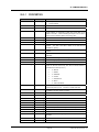
TABLE OF CONTENTS ............................................................... I
TABLES ................................................................................. IX
FIGURES............................................................................... XII
ABOUT THIS MANUAL .......................................................... XVII
1.
INTRODUCTION ................................................................. 1
1.1
1.2
2.
INSTALLING COMPASS....................................................... 5
2.1
2.2
2.3
2.4
2.5
2.6
3.
COMPASS FOR PRESSURE BASIC AND COMPASS FOR PRESSURE ENHANCED........................1
COMPASS SINGLE USER AND SITE LICENSE....................................................................................4
OVERVIEW ..............................................................................................................................................5
SYSTEM REQUIREMENTS.....................................................................................................................6
UNINSTALLING COMPASS FOR PRESSURE ......................................................................................6
UPGRADING FROM COMPASS FOR PPC/RPM ...................................................................................6
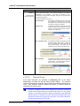
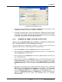
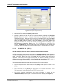
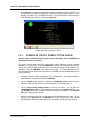
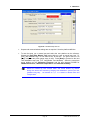
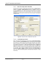
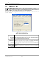
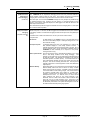
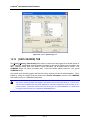
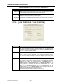
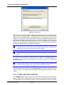
NETWORK/SHARED INSTALLATIONS .................................................................................................6
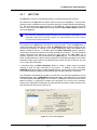
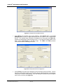
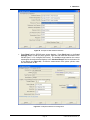
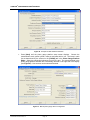
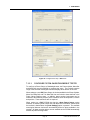
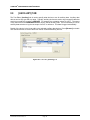
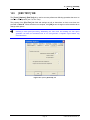
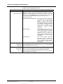
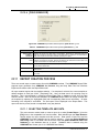
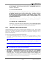
UPDATING EXAMPLE SETUPS .............................................................................................................8
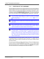
OPERATING PRINCIPLES .................................................... 9
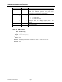
3.1
3.2
3.3
OVERVIEW ..............................................................................................................................................9
RUN MODES .........................................................................................................................................10
DEVICE (INSTRUMENT) SUPPORT CONCEPT ..................................................................................10
3.3.1
3.3.2
3.3.3
3.3.4
3.3.5
3.3.5.1
3.3.5.2
3.3.5.3
3.3.5.4
3.4
USING A MULTIPLEXER ......................................................................................................................16
3.4.1
3.4.2
3.4.2.1
3.4.2.2
3.4.2.3
4.
MEASUREMENT DEVICES ........................................................................................................................10
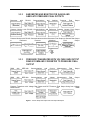
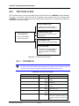
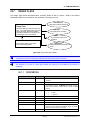
BAROMETER AND MONITOR FOR GAUGE AND ABSOLUTE PRESSURE FINAL OUTPUTS ............11
PRESSURE TRANSDUCER WITH VOLTAGE RAW OUTPUT READ BY DMM AND CONVERTED TO
PRESSURE FINAL OUTPUT ......................................................................................................................11
CONTROL DEVICES ...................................................................................................................................13
OUTPUT CONTROL ....................................................................................................................................13
REGULATION ..........................................................................................................................................14
JOG ..........................................................................................................................................................15
READY/NOT READY ...............................................................................................................................15
PISTON GAUGE READY/NOT READY...................................................................................................16
SWITCHING MULTIPLEXER.......................................................................................................................18
MULTIPLEXERS WITH INTERNAL DMMS ................................................................................................21
DIRECT OUTPUT ....................................................................................................................................21
SWITCHED OUTPUT ..............................................................................................................................22
SCANNED OUTPUTS..............................................................................................................................23
COMMON TOOLS AND FEATURES ...................................... 29
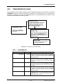
4.1
4.2
4.3
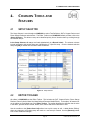
SETUP SELECTOR...............................................................................................................................29
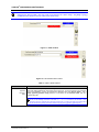
EDITOR TOOLBAR ...............................................................................................................................29
DEVICE EDITORS .................................................................................................................................32
4.3.1
4.3.2
4.3.3
4.3.4
4.3.5
OVERVIEW ..................................................................................................................................................32
CREATING AND EDITING DEVICE DEFINITIONS WITH DEVICE EDITORS ..........................................32
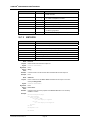
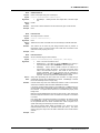
[HEADER] TAB............................................................................................................................................32
[CALIBRATION] TAB ..................................................................................................................................36
[COMMUNICATIONS] TAB .........................................................................................................................39
Page I
© 2002-2004 DH Instruments, Inc.
COMPASS® FOR PRESSURE USER’S MANUAL
4.3.6
4.3.6.1
4.3.6.2
4.3.7
4.3.7.1
4.3.8
4.4
REMOTE COMMAND EDITOR .............................................................................................................68
4.4.1
4.4.2
4.4.2.1
4.4.3
4.4.3.1
4.4.3.2
4.4.4
5.
OVERVIEW ............................................................................................................................................75
MAIN MENU BAR ..................................................................................................................................75
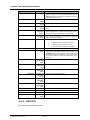
5.2.1
5.2.2
5.2.3
5.2.4
5.2.5
5.2.6
5.2.7
5.3
5.4
5.5
[RUN] ...........................................................................................................................................................75
[SETUP] .......................................................................................................................................................75
[TOOLS].......................................................................................................................................................76
[DATA] .........................................................................................................................................................77
[DATABASE] ...............................................................................................................................................77
[WINDOW] ...................................................................................................................................................77
[HELP]..........................................................................................................................................................77
STATUS BAR ........................................................................................................................................78
MAIN TOOLBAR ...................................................................................................................................78
5.4.1
5.4.2
5.4.3
RUN TEST TOOLS ......................................................................................................................................79
RUN DISPLAY TOOLS................................................................................................................................79
DATA ACQUISITION TOOLS .....................................................................................................................80
RUN SCREENS .....................................................................................................................................82
5.5.1
5.5.2
5.5.3
5.5.4
5.5.4.1
5.5.5
5.5.6
5.5.6.1
5.5.6.2
5.5.7
5.5.8
OVERVIEW ..................................................................................................................................................82
DUT/REFERENCE COMPARISON RUN SCREEN ....................................................................................83
TEST CONDITIONS RUN SCREEN ............................................................................................................84
DEVICE OUTPUT RUN SCREEN ...............................................................................................................85
SPY WINDOWS .......................................................................................................................................86
PISTON GAUGE DEVICE OUTPUT RUN SCREEN...................................................................................87
DHI DEVICE RUN SCREENS......................................................................................................................88
PG7000 RUN SCREEN ...........................................................................................................................89
PPC RUN SCREEN .................................................................................................................................90
DATA GRID RUN SCREEN.........................................................................................................................92
DATA PLOT RUN SCREEN ........................................................................................................................93
HOW DO I? ...................................................................... 95
6.1
6.2
6.3
INITIAL SETUP......................................................................................................................................95
QUICK TIPS...........................................................................................................................................96
APPLICATION EXAMPLES ..................................................................................................................98
6.3.1
6.3.2
6.3.3
6.3.4
6.3.5
6.3.6
6.3.7
6.3.8
7.
INITIALIZATION COMMANDS ....................................................................................................................69
READ OUTPUT COMMANDS .....................................................................................................................69
READY COMMANDS...............................................................................................................................70
CONTROL SET COMMANDS .....................................................................................................................70
ABORT/VENT COMMANDS ....................................................................................................................70
MULTIPLEXER/VALVE DRIVER COMMANDS.......................................................................................71
EDITOR OPTIONS.......................................................................................................................................71
MAIN DISPLAY AND FEATURES ......................................... 75
5.1
5.2
6.
[OUTPUT] TAB ............................................................................................................................................43
[OUTPUT] TAB FOR SIMPLE TYPE DUTS.............................................................................................44
OUTPUT RELATIONSHIP EDITOR.........................................................................................................45
[SET] TAB....................................................................................................................................................59
SET RELATIONSHIP EDITOR ................................................................................................................61
[COMMENT] TAB ........................................................................................................................................68
OVERVIEW ..................................................................................................................................................98
EXAMPLE #1 (DMM) ...................................................................................................................................98
EXAMPLE #2 (DMM, VOLTAGE OUTPUT DUT) .....................................................................................101
EXAMPLE #3 (PPC3) ................................................................................................................................102
EXAMPLE #4 (PG7000) ............................................................................................................................105
EXAMPLE #5 (PG7000, GENERIC PISTON GAUGE) .............................................................................108
EXAMPLE #6 (PG7000,AMH, PPC3) ........................................................................................................112
EXAMPLE #7 (MENSOR PCS-400) ..........................................................................................................114
RUN MODES ...................................................................119
7.1
7.2
7.3
OVERVIEW .......................................................................................................................................... 119
[RUN], [RUN TEST] ............................................................................................................................. 119
TEST INITIALIZATION ........................................................................................................................ 120
7.3.1
7.3.2
7.3.3
7.3.3.1
7.3.3.2
SELECT UNITS OF MEASURE ................................................................................................................121
SELECT DUT(S) ........................................................................................................................................121
CONFIGURE DUT(S)/DEVICES ................................................................................................................122
MULITPLE RAW OUTPUT DEVICES....................................................................................................124
CONFIGURE DHI DEVICE ....................................................................................................................124
© 2002-2004 DH Instruments, Inc.
Page II
TABLE OF CONTENTS
7.3.3.3
7.3.4
7.3.5
7.3.6
7.3.7
7.4
RUN TEST ........................................................................................................................................... 130
7.4.1
7.5
8.
TEST CONCLUSION .................................................................................................................................136
[RUN], [RUN MANUAL TEST] ............................................................................................................ 138
[SETUP], [TEST] ............................................................. 139
8.1
8.2
8.3
8.4
8.5
OVERVIEW .......................................................................................................................................... 139
TEST EDITOR...................................................................................................................................... 139
CREATING TEST DEFINITIONS......................................................................................................... 139
EDITING TEST DEFINITIONS ............................................................................................................. 140
[PRE-TEST] TAB ................................................................................................................................. 140
8.5.1
8.5.2
8.5.3
8.6
8.7
8.8
PRE-TEST MACRO ...................................................................................................................................141
LEAK TEST FRAME..................................................................................................................................141
EXERCISE FRAME....................................................................................................................................142
TEST POINT SEQUENCE ................................................................................................................... 143
8.6.1
8.6.2
8.6.3
8.6.4
8.6.5
8.6.6
8.6.7
9.
CONFIGURE PISTON GAUGE/DEADWEIGHT TESTER.....................................................................125
SELECT TEST ...........................................................................................................................................126
VERIFY/SELECT TEST HARDWARE.......................................................................................................128
CONFIGURE TEST HARDWARE .............................................................................................................129
FINAL VERIFICATION...............................................................................................................................129
OVERVIEW ................................................................................................................................................143
TEST POINT SEQUENCE, INSERT OPTIONS.........................................................................................144
CUSTOM POINT OPERATIONS ...............................................................................................................146
AUTO FILL.................................................................................................................................................147
TEST POINTS SEQUENCE, [GENERAL] CHILD TAB ............................................................................148
TEST POINTS SEQUENCE, [READ] CHILD TAB....................................................................................150
TEST POINTS SEQUENCE, [SET] CHILD TAB .......................................................................................151
[DATA] TAB......................................................................................................................................... 154
[AUXILIARY] TAB ............................................................................................................................... 156
[SETUP], [DUT] ..............................................................157
9.1
9.2
OVERVIEW .......................................................................................................................................... 157
DUT EDITOR ....................................................................................................................................... 158
10. [SETUP], [SUPPORT DEVICE] ...........................................159
10.1
11.
OVERVIEW .......................................................................................................................................... 159
[SETUP], [PISTON GAUGE] .............................................. 161
11.1
11.2
OVERVIEW .......................................................................................................................................... 161
[PISTON GAUGE PLATFORM] ........................................................................................................... 161
11.2.1
11.2.2
11.2.3
11.2.4
11.2.5
11.2.6
11.2.7
11.3
[PISTON-CYLINDER] .......................................................................................................................... 166
11.3.1
11.3.2
11.3.3
11.3.4
11.3.4.1
11.3.4.2
11.4
[HEADER] TAB..........................................................................................................................................163
[CALIBRATION] TAB ................................................................................................................................163
[P-C/MS] TAB ............................................................................................................................................163
[SOURCES] TAB .......................................................................................................................................164
[COMMUNICATIONS] TAB .......................................................................................................................165
[OUTPUT] TAB ..........................................................................................................................................166
[SET] TAB..................................................................................................................................................166
[HEADER] TAB..........................................................................................................................................166
[CALIBRATION] TAB ................................................................................................................................167
[TOLERANCE] TAB ..................................................................................................................................167
[CHARACTERISTICS] TAB ......................................................................................................................167
PISTON GAUGE TYPE PISTON-CYLINDER........................................................................................167
DEADWEIGHT TESTER TYPE PISTON-CYLINDER............................................................................169
[MASS SET] ......................................................................................................................................... 169
11.4.1
[HEADER] TAB..........................................................................................................................................170
11.4.2
[CALIBRATION] TAB ................................................................................................................................170
11.4.3
[MASS SET] TAB ......................................................................................................................................170
11.4.3.1
PISTON GAUGE TYPE MASS SET ......................................................................................................171
11.4.3.2
PISTON GAUGE TRIM MASS TYPE MASS SET .................................................................................172
11.4.3.3
DEAWEIGHT TESTER TYPE MASS SET.............................................................................................173
11.5
[MASS BELL] ...................................................................................................................................... 175
11.5.1
[HEADER] TAB..........................................................................................................................................175
Page III
© 2002-2004 DH Instruments, Inc.
COMPASS® FOR PRESSURE USER’S MANUAL
11.5.2
11.5.3
11.6
[CALIBRATION] TAB ................................................................................................................................175
[MASS BELL] TAB ....................................................................................................................................176
DHI PG7000 ......................................................................................................................................... 177
12. [SETUP], [DEFAULT HARDWARE CONFIGURATION] ...........179
12.1
12.2
12.3
12.4
OVERVIEW .......................................................................................................................................... 179
[ENVIRONMENT] TAB ........................................................................................................................ 179
[ELECTRICAL] TAB ............................................................................................................................ 180
[AUXILIARY] TAB................................................................................................................................ 181
13. [SETUP], [PRESSURE MEDIA] ..........................................183
14.
[TOOLS], [OPTIONS] .......................................................185
14.1
14.2
14.3
14.4
14.5
14.6
14.7
14.8
14.9
14.10
14.11
14.12
15.
OVERVIEW .......................................................................................................................................... 185
[AMBIENT CONDITIONS] TAB ........................................................................................................... 185
[INITIALIZE TEST] TAB....................................................................................................................... 186
[RUN TEST] TAB ................................................................................................................................. 188
[END TEST] TAB ................................................................................................................................. 191
[PISTON GAUGE] TAB ....................................................................................................................... 193
[DATA GRID] TAB ............................................................................................................................... 194
[DATA FILE] TAB ................................................................................................................................ 195
[DATA IN FILE] TAB............................................................................................................................ 197
[DATA HEADER] TAB......................................................................................................................... 198
[INTERFACE] TAB .............................................................................................................................. 199
[LANGUAGE] TAB .............................................................................................................................. 200
[TOOLS], [REMOTE COMMUNICATIONS]............................201
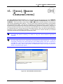
16. [TOOLS], [PISTON GAUGE CALCULATOR] .........................203
16.1
16.2
16.3
17.
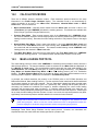
[TOOLS], [PG7000 SETUP EXTRACTOR] ............................ 209
17.1
18.
OVERVIEW .......................................................................................................................................... 203
CALCULATION MODES...................................................................................................................... 208
MASS LOADING PROTOCOL............................................................................................................. 208
OVERVIEW .......................................................................................................................................... 209
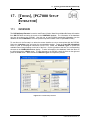
[TOOLS], [COMPASS MACRO EDITOR] .............................. 211
18.1
18.2
18.3
18.4
18.5
OVERVIEW .......................................................................................................................................... 211
VB SCRIPT .......................................................................................................................................... 212
USING THE MACRO EDITOR ............................................................................................................. 213
TROUBLESHOOTING MACROS ........................................................................................................ 214
MACRO TYPES ................................................................................................................................... 215
18.5.1
18.5.2
18.5.3
18.5.4
18.5.5
18.5.6
18.5.7
18.5.8
18.6
18.7
DATA FILE MACROS................................................................................................................................217
GET COMMAND MACROS .......................................................................................................................218
GLOBAL MACROS ...................................................................................................................................220
INTERFACE MACROS ..............................................................................................................................221
RELATIONSHIP MACROS........................................................................................................................223
REPLY PARSER MACROS ......................................................................................................................225
REPORT MACROS ...................................................................................................................................228
TEST MACROS .........................................................................................................................................230
THREADING MODEL .......................................................................................................................... 231
VARIABLE AND FUNCTION SCOPE.................................................................................................. 232
© 2002-2004 DH Instruments, Inc.
Page IV
TABLE OF CONTENTS
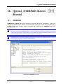
19.
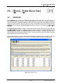
[DATA], [VIEW DATA FILE] ..............................................233
19.1
OVERVIEW .......................................................................................................................................... 233
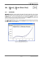
20. [DATA], [PLOT DATA FILE] ..............................................235
20.1
20.2
20.3
20.4
20.5
21.
OVERVIEW .......................................................................................................................................... 235
PLOT TOOLBAR ................................................................................................................................. 236
PLOT OPTIONS MENU ....................................................................................................................... 236
CREATE/EDIT PLOTS......................................................................................................................... 236
PLOT POINTS...................................................................................................................................... 238
[DATA], [DATABASE DATA VIEWER] .................................241
21.1
21.2
21.3
21.4
21.5
OVERVIEW .......................................................................................................................................... 241
COMPASS DATA VIEWER ................................................................................................................. 241
DATABASE PRINCIPLES ................................................................................................................... 243
CREATE SEARCH QUERY ................................................................................................................. 244
DATABASE TABLES AND FIELDS. ................................................................................................... 245
21.5.1
21.5.2
21.5.3
22.
EXPORTING COMPASS DATA ...........................................253
22.1
22.2
22.3
OVERVIEW .......................................................................................................................................... 253
EXPORT TO EXCEL® ......................................................................................................................... 253
EXPORT TO MET/CAL ........................................................................................................................ 256
22.3.1
22.3.2
22.3.3
22.3.4
23.
TEST TABLE .............................................................................................................................................245
DEVICES TABLE.......................................................................................................................................247
DATA TABLE.............................................................................................................................................249
CREATING THE CALIBRATION RECORD ..............................................................................................256
CREATING A MET/CAL SOURCE FILE ...................................................................................................257
IMPORTING COMPLETE TEST RECORD ...............................................................................................258
IMPORTING SPECIFIC DATA INTO RESULTS TABLE ..........................................................................259
[DATA], [REPORT EDITOR] ..............................................263
23.1
23.2
23.3
23.4
OVERVIEW .......................................................................................................................................... 263
REPORT PRINCIPLES ........................................................................................................................ 263
MAIN DISPLAY .................................................................................................................................... 265
MAIN MENU BAR ................................................................................................................................ 265
23.4.1
23.4.2
23.4.3
23.4.4
23.4.5
23.4.6
23.4.7
23.4.8
23.4.9
23.5
23.6
23.7
23.8
23.9
[FILE] .........................................................................................................................................................266
[EDIT] .........................................................................................................................................................268
[VIEW] ........................................................................................................................................................269
[INSERT] ....................................................................................................................................................270
[FORMAT]..................................................................................................................................................270
[TABLE] .....................................................................................................................................................271
[TOOLS].....................................................................................................................................................271
[WINDOW] .................................................................................................................................................271
[HELP]........................................................................................................................................................271
MAIN TOOLBAR.................................................................................................................................. 272
FORMAT TOOLBAR............................................................................................................................ 273
RULER 275
STATUS BAR ...................................................................................................................................... 275
OPTIONS ............................................................................................................................................. 275
23.9.1
23.9.2
23.9.3
23.9.4
[REPORTS] TAB .......................................................................................................................................276
[REPORT GENERATION] .........................................................................................................................278
[TEMPLATES] TAB ...................................................................................................................................279
[GENERAL] TAB .......................................................................................................................................280
23.10 FIELD PROPERTIES ........................................................................................................................... 281
23.10.1
23.10.2
23.10.3
23.10.4
FIELD PROPERTIES FORM .....................................................................................................................281
[DATA FORMAT].......................................................................................................................................281
[DATA SOURCE AND CYCLE SELECTION] ...........................................................................................282
[FIELD BEHAVIOR]...................................................................................................................................283
23.11 REPORT CREATION PROCESS......................................................................................................... 283
Page V
© 2002-2004 DH Instruments, Inc.
COMPASS® FOR PRESSURE USER’S MANUAL
23.11.1
23.11.2
23.11.3
23.11.4
SELECTING TEMPLATE AND DATA.......................................................................................................283
DRAG AND DROP CREATION .................................................................................................................284
SAVING REPORTS ...................................................................................................................................285
DISPLAY / VIEW REPORTS .....................................................................................................................285
23.12 TEMPLATE CREATION PROCESS .................................................................................................... 285
23.12.1
23.12.2
AVAILABLE DATA FIELDS ......................................................................................................................286
TABLES .....................................................................................................................................................287
24. [DATABASE], [SETUP] .....................................................289
24.1
24.2
24.3
24.4
24.5
OVERVIEW .......................................................................................................................................... 289
[DATABASE], [SETUP] ....................................................................................................................... 289
[DATABASE], [USERS]....................................................................................................................... 290
[DATABASE], [CHANGE CURRENT USER] ...................................................................................... 291
[DATABASE][COMPASS DATABASE MAINTENENCE TOOL] ........................................................ 292
25. REMOTE INTERFACING ...................................................295
25.1
25.2
OVERVIEW .......................................................................................................................................... 295
RS232 INTERFACE ............................................................................................................................. 296
25.2.1
25.2.2
25.3
25.4
25.5
IEEE-488 INTERFACE......................................................................................................................... 297
TCP/IP 298
HART VIA RS232................................................................................................................................. 298
25.5.1
25.6
RS232 SETUP............................................................................................................................................296
DHI DEVICE COM2....................................................................................................................................297
HART OUTPUT REQUIREMENTS............................................................................................................299
TERMINATION AND TIMEOUT ........................................................................................................... 301
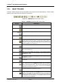
26. UNIT CONVERSIONS .......................................................303
27. DATA FILES ...................................................................305
27.1
27.2
27.3
28.
DATA FILE CREATION ....................................................................................................................... 305
NAMING AND STORING DATA FILES ............................................................................................... 305
DATA FILE STRUCTURE .................................................................................................................... 306
COMPASS OBJECTS ........................................................309
28.1
28.2
OVERVIEW .......................................................................................................................................... 309
OBJECT CONSTANTS........................................................................................................................ 310
28.2.1
28.2.2
28.2.3
28.2.4
28.3
PRESSURE UNIT CONSTANTS ...............................................................................................................310
PRESSURE MEASUREMENT MODE.......................................................................................................311
TEMPERATURE UNITS ............................................................................................................................311
MANUAL/AUTOMATIC .............................................................................................................................311
TEST DATA CLASS ............................................................................................................................ 312
28.3.1
PROPERTIES ............................................................................................................................................312
28.3.1.1
DEVICE HEADER CLASS .....................................................................................................................314
28.3.1.2
GENERAL HEADER CLASS .................................................................................................................315
28.3.1.3
TEST HEADER CLASS .........................................................................................................................316
28.3.1.4
TEST DATA POINT CLASS...................................................................................................................317
28.3.2
METHODS..................................................................................................................................................319
28.3.2.1
DATAPOINTREF....................................................................................................................................319
28.4
TEST DEFINITION CLASS .................................................................................................................. 320
28.4.1
28.4.2
28.4.3
28.5
DEVICE CLASS ................................................................................................................................... 324
28.5.1
28.5.2
28.6
PROPERTIES ............................................................................................................................................325
METHODS..................................................................................................................................................326
CONFIGURATION CLASS .................................................................................................................. 327
28.6.1
28.6.2
28.7
PROPERTIES ............................................................................................................................................320
TEST POINT CLASS .................................................................................................................................323
CONTROL SETTINGS CLASS..................................................................................................................324
PROPERTIES ............................................................................................................................................327
METHODS..................................................................................................................................................328
RANGE CLASS.................................................................................................................................... 329
© 2002-2004 DH Instruments, Inc.
Page VI
TABLE OF CONTENTS
28.7.1
28.7.2
28.8
CALCULATION CLASS....................................................................................................................... 335
28.8.1
28.8.2
28.9
PROPERTIES ............................................................................................................................................329
METHODS..................................................................................................................................................332
PROPERTIES ............................................................................................................................................335
METHODS..................................................................................................................................................338
COMPASS CLASS .............................................................................................................................. 341
28.9.1
28.9.2
PROPERTIES ............................................................................................................................................342
METHODS..................................................................................................................................................344
29. CALCULATIONS ..............................................................351
29.1
29.2
29.3
29.4
29.5
29.6
29.7
29.8
ERRORS .............................................................................................................................................. 351
TOLERANCE ....................................................................................................................................... 352
BEST FIT.............................................................................................................................................. 353
LINEARITY........................................................................................................................................... 353
HYSTERESIS ....................................................................................................................................... 354
REPEATABILITY ................................................................................................................................. 354
MEASUREMENT UNCERTAINTY ....................................................................................................... 354
PISTON GAUGE PRESSURE CALCULATIONS ................................................................................ 355
29.8.1
29.8.2
29.8.3
29.8.4
29.9
GAUGE MODE: .........................................................................................................................................356
ABSOLUTE PRESSURE BY ADDING ATMOSPHERIC PRESSURE: ....................................................356
ABSOLUTE PRESSURE WITH VACUUM REFERENCE: .......................................................................356
DIFFERENTIAL PRESSURE (DIFFERENTIAL MODE): ..........................................................................356
FLUID HEADS...................................................................................................................................... 357
29.9.1
29.9.2
FLUID HEAD COMPONENTS ...................................................................................................................357
OVERALL FLUID HEAD CORRECTION ..................................................................................................359
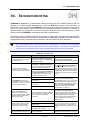
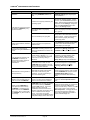
30. TROUBLESHOOTING .......................................................361
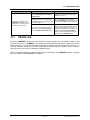
30.1
ERROR LOG ........................................................................................................................................ 363
31. GLOSSARY .....................................................................365
Page VII
© 2002-2004 DH Instruments, Inc.
COMPASS® FOR PRESSURE USER’S MANUAL
NOTES
© 2002-2004 DH Instruments, Inc.
Page VIII
TABLES & FIGURES
TABLES
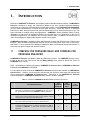
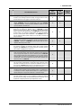
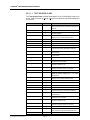
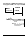
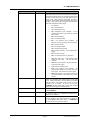
Table 1. Features of COMPASS for Pressure Basic and Enhanced Versions............................................ 1
Table 2. Common Multiplexer Channel Commands .................................................................................. 19
Table 3. Switching Multiplexer Get Command Macros.............................................................................. 20
Table 4. Pros and Cons of Multiplexer Setups with Internal DMMs........................................................... 21
Table 5. Common Multiplexer Channel and Measurement Commands.................................................... 23
Table 6. Multiplexer Scanned Output Macros............................................................................................ 25
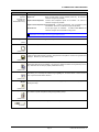
Table 7. Editor Toolbar Features ............................................................................................................... 30
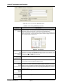
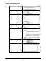
Table 8. Device Editor, [Header] Tab Fields .............................................................................................. 34
Table 9. Device Editor, [Calibration] Tab Fields......................................................................................... 38
Table 10. Device Editor, [Communications] Tab Fields............................................................................ 41
Table 11. Device Editor, [Output] Tab Fields ............................................................................................. 44
Table 12. Output Relationship Editor, [Raw Output] Tab Fields ................................................................ 48
Table 13. Raw Output Type and Possible Output Sources ....................................................................... 50
Table 14. Output Relationship Editor, [Final Output] Tab Fields ............................................................... 53
Table 15. Final Output Types and Possible Final Outputs ........................................................................ 54
Table 16. Output Relationship Editor, [Tolerance] Tab Fields ................................................................... 55
Table 17. Tolerance Type Choices ............................................................................................................ 57
Table 18. Device Editor, [Set] Tab Fields .................................................................................................. 60
Table 19. Set Relationship Editor, [Raw Set] Tab Fields........................................................................... 63
Table 20. Raw Set Type and Possible Set Sources .................................................................................. 65
Table 21. Set Relationship Editor, [Final Set] Tab Fields .......................................................................... 67
Table 22. Set Types and Possible Final Sets ............................................................................................ 67
Table 23. Remote Command Editor, [Command] Tab Fields.................................................................... 71
Table 24. Remote Command Editor, [Global Settings] Tab Options ......................................................... 73
Table 25. Main Toolbar, Run Test Tools.................................................................................................... 79
Table 26. Main Toolbar, Run Display Tools............................................................................................... 80
Table 27. <Control> Toolbar, Data Acquisition Options ............................................................................ 81
Table 28. DUT/Reference Comparison Run Screen Fields...................................................................... 84
Table 29. Conditions Run Screen Fields ................................................................................................... 85
Table 30. Spy Window Information ............................................................................................................ 87
Table 31. PG7000 Run Screen Fields ....................................................................................................... 89
Table 32. PPC Run Screen Fields ............................................................................................................. 91
Table 33. <Test Complete> Panel Options.............................................................................................. 137
Table 34. Test Editor, [Pre-Test] Tab, <Leak Test> Fields...................................................................... 141
Table 35. <Test Editor>, [Pre-Test] Tab, Exercise Frame Fields ............................................................ 143
Table 36. Insert Options Choices............................................................................................................. 145
Table 37. Custom Operation Point Label Definitions............................................................................... 146
Table 38. Auto Fill Points Fields .............................................................................................................. 147
Table 39. Test Definition Editor, Point Sequence Tab, [General] Child Tab Fields................................. 148
Table 40. Configure Device Dialogue Fields............................................................................................ 151
Table 41. Test Definition Editor, Points Sequence Tab, [Set] Child Tab for Pressure Controller Fields . 152
Table 42. Test Definition Editor, Points Sequence Tab, [Set] Child Tab for a PG7000 Fields................ 153
Table 43. Test Editor, [Data] Tab Fields .................................................................................................. 155
Table 44. Piston Gauge Platform Editor, [P-C/MS] Tab Fields................................................................ 164
Page IX
© 2002-2004 DH Instruments, Inc.
COMPASS® FOR PRESSURE USER’S MANUAL
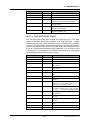
Table 45.
Table 46.
Table 47.
Table 48.
Table 49.
Table 50.
Table 51.
Table 52.
Table 53.
Table 54.
Table 55.
Table 56.
Table 57.
Table 58.
Table 59.
Table 60.
Table 61.
Table 62.
Table 63.
Table 64.
Table 65.
Table 66.
Table 67.
Table 68.
Table 69.
Table 70.
Table 71.
Table 72.
Table 73.
Table 74.
Table 75.
Table 76.
Table 77.
Table 78.
Table 79.
Table 80.
Table 81.
Table 82.
Table 83.
Table 84.
Table 85.
Table 86.
Table 87.
Table 88.
Table 89.
Table 90.
Table 91.
Table 92.
Table 93.
Table 94.
Piston Gauge Platform Editor, [Sources] Tab Fields ............................................................... 165
Piston-Cylinder Editor, Piston Gauge Type [Characteristics] Tab Fields ................................ 168
Piston-Cylinder Editor, Deadweight Tester Type [Characteristics] Tab Fields ........................ 169
Mass Set Editor, Piston Gauge Type [Mass Set] Tab Fields................................................... 172
Mass Set Editor, Piston Gauge Trim Mass Type [Mass Set] Tab Fields................................. 173
Mass Set Editor, Deadweight Tester Type [Mass Set] Tab Fields .......................................... 174
Mass Bell Editor, [Mass Bell] Tab Fields ................................................................................. 176
Default Hardware Configuration, [Environment] Tab Fields .................................................... 180
Default Hardware Configuration, [Electrical] Tab Fields .......................................................... 181
Pressure Media Editor Fields................................................................................................... 184
COMPASS Options, [Ambient Conditions] Tab Sélections ..................................................... 186
Options, [Initialize Test] Tab Fields.......................................................................................... 187
Options, [Run Test] Tab Fields ................................................................................................ 188
Options, [End Test] Tab Fields ................................................................................................ 192
Options, [Piston Gauge] Tab Fields ......................................................................................... 193
Options, [Data Grid] Tab Selections ........................................................................................ 195
Options, [Data File] Tab Fields ................................................................................................ 196
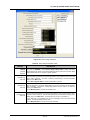
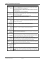
Piston Gauge Calculator Fields ............................................................................................... 205
COMPASS Macro Types Summary......................................................................................... 215
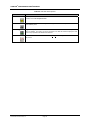
Data File Viewer Options ......................................................................................................... 234
Data Plot Toolbar ..................................................................................................................... 236
Custom Plot Editor Fields ........................................................................................................ 238
Plot Points Genera Tab Fields ................................................................................................ 239
Plot Points Best Fit Tab Fields................................................................................................. 240
Data Viewer Toolbar ................................................................................................................ 242
Test Record Information Fields................................................................................................ 243
Description of fields in the Test Table...................................................................................... 245
Device Type Descriptions ........................................................................................................ 247
Description of fields in the Devices Table................................................................................ 248
Description of fields in the Data Table ..................................................................................... 250
Data Imported into MET/CAL................................................................................................... 260
COMPASS Report Editor, [File] Menu Fields .......................................................................... 267
COMPASS Report Editor, [Edit] Menu Fields.......................................................................... 268
COMPASS Report Editor, [View] Menu Fields ........................................................................ 269
COMPASS Report Editor, [Insert] Menu Fields ....................................................................... 270
COMPASS Report Editor, [Tools] Menu Fields ....................................................................... 271
COMPASS Report Editor, Main Toolbar Fields ....................................................................... 272
COMPASS Report Editor, Format Toolbar Fields ................................................................... 273
COMPASS Report Editor, Ruler Options................................................................................. 275
COMPASS Report Editor Options, Reports Options ............................................................... 276
COMPASS Report Editor Options, Report Generation Options .............................................. 278
COMPASS Report Editor Options, Templates Options ........................................................... 279
COMPASS Report Editor, Ruler Options................................................................................. 280
COMPASS Report Editor Field Properties .............................................................................. 281
COMPASS Report Editor Field Properties, [Data Format] Tab ............................................... 282
COMPASS Report Editor Field Properties, [Data Source…] Tab ........................................... 282
COMPASS Report Editor Field Properties, [Data Source…] Tab ........................................... 283
COMPASS Report Editor Available Data Fields...................................................................... 286
COMPASS Users Selections and Associated Rights .............................................................. 291
COMPASS Database Maintenance Tool................................................................................. 293
© 2002-2004 DH Instruments, Inc.
Page X
TABLES & FIGURES
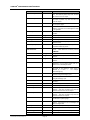
Table 95. Command Termination and Timeout Frame Labels ................................................................ 301
Table 96. Data File Structure ................................................................................................................... 306
Table 97. COMPASS Object Summary ................................................................................................... 309
Table 98. Pressure Unit Constants .......................................................................................................... 310
Table 99. Pressure Measurement Mode Constants ................................................................................ 311
Table 100. Temperature Unit Constants.................................................................................................. 311
Table 101. Manual/Automatic .................................................................................................................. 311
Table 102. Test Data Class Properties .................................................................................................... 312
Table 103. Test Data Class Method Summary ........................................................................................ 319
Table 104. Test Definition Class Properties............................................................................................. 320
Table 105. Test Point Class ..................................................................................................................... 323
Table 106. Test Point Class ..................................................................................................................... 324
Table 107. PG7000 Defined Pressure Calculation Variables .................................................................. 355
Table 108. Troubleshooting ..................................................................................................................... 361
Page XI
© 2002-2004 DH Instruments, Inc.
COMPASS® FOR PRESSURE USER’S MANUAL
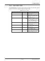
FIGURES
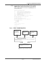
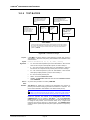
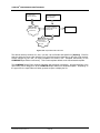
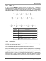
Figure 1. Device Setup Raw Output and Final Output Examples.............................................................. 11
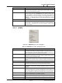
Figure 2. Set Jog........................................................................................................................................ 15
Figure 3. Multiplexer Set Relationship ....................................................................................................... 17
Figure 4. Typical Multiplexer Connection ......................................................................................................... 18
Figure 5. Common Multiplexer Command Setup....................................................................................... 19
Figure 6. Multiplexer Individual Output Setup ............................................................................................ 22
Figure 7. Multiplexer Channel Specific Output Source Selection .............................................................. 22
Figure 8. Multiplexer Scanned Output Command Setup ........................................................................... 24
Figure 9. Multiplexer Scanned Set Command Setup................................................................................. 24
Figure 10. Setup Selector .......................................................................................................................... 29
Figure 11. Editor Toolbar ........................................................................................................................... 30
Figure 12. Test Definition Editor Toolbar .................................................................................................... 30
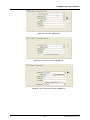
Figure 13. DUT Editor, [Header] Tab ......................................................................................................... 33
Figure 14. Support Device Editor, [Header] Tab....................................................................................... 33
Figure 15. Piston Gauge Platform Editor, [Header] Tab ............................................................................ 33
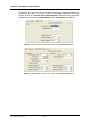
Figure 16. DUT Editor, [Calibration] Tab.................................................................................................... 37
Figure 17. Support Device Editor, [Calibration] Tab .................................................................................. 37
Figure 18. Piston-Cylinder Editor, [Calibration] Tab .................................................................................. 38
Figure 19. Date Selection........................................................................................................................... 38
Figure 20. Common Read and Set Interface Setups on the [Communications] Tab................................. 40
Figure 21. Individual Read and Set Interface Setups on the [Communications] Tab ................................ 40
Figure 22. Device Editor, [Output] Tab ...................................................................................................... 43
Figure 23. DUT Device Edit [Output] Tab for a Simple Type DUT ............................................................ 44
Figure 24. Output Relationship Editor, [Raw Output] Tab ......................................................................... 46
Figure 25. More Than One Raw Output on the [Raw Output] Tab ............................................................ 46
Figure 26. Output Relationship Editor, [Final Output] Tab......................................................................... 51
Figure 27. Output Relationship Editor, [Tolerance] Tab ............................................................................ 55
Figure 28. Output Relationship Editor, [Tolerance] Tab ............................................................................ 57
Figure 29. %Reading Tolerance ................................................................................................................ 57
Figure 30. %Span Tolerance ..................................................................................................................... 57
Figure 31. %Span or %Reading (Greater of)............................................................................................. 58
Figure 32. %Span + %Reading.................................................................................................................. 58
Figure 33. Device Editor, [Set] Tab............................................................................................................ 59
Figure 34. Set Relationship Editor, [Raw Set] Tab .................................................................................... 62
Figure 35. Set Relationship Editor, [Final Set] Tab.................................................................................... 66
Figure 36. Test Definition Editor, [Comment] Tab ..................................................................................... 68
Figure 37. Remote Command Editor ......................................................................................................... 69
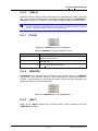
Figure 38. <Status Bar> ............................................................................................................................. 78
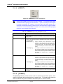
Figure 39. Test Status................................................................................................................................ 78
Figure 40. Main Toolbar ............................................................................................................................. 78
Figure 41. Manual Averaging Options ....................................................................................................... 81
Figure 42. <Average Setup> ...................................................................................................................... 82
Figure 43. DUT/Reference Comparison Run Screen ............................................................................... 83
Figure 44. Conditions Run Screen............................................................................................................. 85
© 2002-2004 DH Instruments, Inc.
Page XII
TABLES & FIGURES
Figure 45.
Figure 46.
Figure 47.
Figure 48.
Figure 49.
Figure 50.
Figure 51.
Figure 52.
Figure 53.
Figure 54.
Figure 55.
Figure 56.
Figure 57.
Figure 58.
Figure 59.
Figure 60.
Figure 61.
Figure 62.
Figure 63.
Figure 64.
Figure 65.
Figure 66.
Figure 67.
Figure 68.
Figure 69.
Figure 70.
Figure 71.
Figure 72.
Figure 73.
Figure 74.
Figure 75.
Figure 76.
Figure 77.
Figure 78.
Figure 79.
Figure 80.
Figure 81.
Figure 82.
Figure 83.
Figure 84.
Figure 85.
Figure 86.
Figure 87.
Figure 88.
Figure 89.
Figure 90.
Figure 91.
Figure 92.
Figure 93.
Figure 94.
Device Output Run Screen ....................................................................................................... 86
Spy Window Screen ................................................................................................................. 87
Piston Gauge Run Screen ........................................................................................................ 88
PG7000 Run Screen................................................................................................................. 89
PPC Run Screen....................................................................................................................... 91
Data Grid Run Screen .............................................................................................................. 92
Data Plot Run Screen ............................................................................................................... 93
Example Voltage Raw Output Setup ........................................................................................ 99
Example Voltage Final Output Setup ....................................................................................... 99
Example DMM Remote Command Setup .............................................................................. 100
Example DMM Output Tab ..................................................................................................... 101
Example Voltage DUT Setup.................................................................................................. 102
Example PPC3 Setup ............................................................................................................. 103
Example PPC3 Hardware Selection ....................................................................................... 104
Example PPC3 Device Configuration ..................................................................................... 104
Example PPC3 Run Screen ................................................................................................... 105
Example PG7601 Setup ......................................................................................................... 106
Example PG7000 Hardware Selection ................................................................................... 107
Example PG7000 Device Configuration ................................................................................. 107
Example PG7000 Run Screen................................................................................................ 108
PG7000 Setup Sources .......................................................................................................... 109
Example PG7000 Hardware Selection ................................................................................... 110
Manual piston gauge device Configuration ............................................................................ 110
PG7000 Base used for sensory output................................................................................... 111
Manual Piston Gauge with autodetect PG7000 Base ............................................................ 112
PG7000 AMH, PPC RS232 Connections ............................................................................... 113
PG7000 AMH, Test Definition Set Requirements................................................................... 114
mensor PCS-400 Header Setup ............................................................................................. 115
mensor PCS-400 Communications Setup.............................................................................. 115
mensor PCS-400 Output Relationship ................................................................................... 116
mensor PCS-400 Remote Command Setup .......................................................................... 116
mensor PCS-400 Set Relationship ......................................................................................... 117
mensor PCS-400 Initialization Command Setup .................................................................... 117
mensor PCS-400 Set Command Setup.................................................................................. 117
mensor PCS-400 Vent Command Selection .......................................................................... 118
mensor PCS-400 Vent Command Setup................................................................................ 118
Run Test Setup Select Units of Measure ............................................................................... 121
Run Test Setup Select DUTs.................................................................................................. 122
Configure DUT Step – Profile DUT......................................................................................... 123
Configure DUT Step – Mulitiple Raw Output DUT................................................................. 124
Configure DUT Step – DHI Device ......................................................................................... 125
Configure Piston Gauge ......................................................................................................... 126
Select Test Definition.............................................................................................................. 127
Select Test Definition using <View> ....................................................................................... 127
Test Hardware Configuration.................................................................................................. 129
Test Definition Flow Chart ...................................................................................................... 131
Set Pressure with Non DHI Piston Gauge.............................................................................. 134
Set Pressure with a DHI Piston Gauge .................................................................................. 135
<Test Complete> Panel .......................................................................................................... 137
Test Editor, [Pre-Test] Tab ..................................................................................................... 140
Page XIII
© 2002-2004 DH Instruments, Inc.
COMPASS® FOR PRESSURE USER’S MANUAL
Figure 95. [Pressure] Point Sequence Tab.............................................................................................. 144
Figure 96. Insert Options.......................................................................................................................... 144
Figure 97. Driver State Selector............................................................................................................... 145
Figure 98. Test Macro Selector................................................................................................................ 146
Figure 99. Custom Operation Point Labels.............................................................................................. 146
Figure 100. Auto Fill Pressure Points ...................................................................................................... 147
Figure 101. Test Definition Editor, Point Sequence Tab, [General] Child Tab ........................................ 148
Figure 102. Test Definition Editor, Point Sequence Tab, [Read] Child Tab ............................................ 150
Figure 103. Configure Device Dialogue ................................................................................................... 150
Figure 104. Test Definition Editor, [Set] Child Tab for a Pressure Controller .......................................... 151
Figure 105. Test Definition Editor, Advanced Test [Set] Child Tab for a Pressure Controller................. 152
Figure 106. Test Definition Editor, Points Sequence Tab, [Set] Child Tab for a PG7000 ....................... 153
Figure 107. Test Editor, [Data] Tab.......................................................................................................... 154
Figure 108. Test Editor, [Auxiliary] Tab.................................................................................................... 156
Figure 109. Piston-Cylinder Selector ....................................................................................................... 163
Figure 110. Piston Gauge Platform Editor, [P-C/MS] Tab ....................................................................... 164
Figure 111. Piston Gauge Platform Editor, [Sources] Tab....................................................................... 165
Figure 112. Piston-Cylinder Editor, Piston Gauge Type [Characteristics] Tab........................................ 167
Figure 113. Piston-Cylinder Editor, Deadweight Tester Type [Characteristics] Tab ............................... 169
Figure 114. Mass Set Editor, Piston Gauge Type [Mass Set] Tab .......................................................... 171
Figure 115. Mass Set Editor, Piston Gauge Trim Mass Type [Mass Set] Tab ........................................ 173
Figure 116. Mass Set Editor, Deadweight Tester Type [Mass Set] Tab.................................................. 174
Figure 117. Mass Bell Editor, [Mass Bell] Tab ......................................................................................... 176
Figure 118. Default Hardware Configuration, [Environment] Tab............................................................ 180
Figure 119. Default Hardware Configuration, [Electrical] Tab ................................................................. 181
Figure 120. Default Hardware Configuration [Auxiliary] Tab ................................................................... 182
Figure 121. Pressure Media Editor .......................................................................................................... 183
Figure 122. Options, [Ambient Conditions] Tab ....................................................................................... 185
Figure 123. Options, [Initialize Test] Tab ................................................................................................. 186
Figure 124. Options, [Run Test] Tab........................................................................................................ 188
Figure 125. Options, [End Test] Tab........................................................................................................ 191
Figure 126. Options, [Piston Gauge] Tab ................................................................................................ 193
Figure 127. Options, [Data Grid] Tab....................................................................................................... 195
Figure 128. Options, [Data File] Tab........................................................................................................ 196
Figure 129. Options, [Data In File] Tab.................................................................................................... 198
Figure 130. Options, [Data Header] Tab.................................................................................................. 199
Figure 131. <COMPASS Options> [Interface] Tab.................................................................................. 200
Figure 132. Options, [Language] Tab ...................................................................................................... 200
Figure 133. <Direct Remote Communication>......................................................................................... 201
Figure 134. Unit Selector ......................................................................................................................... 204
Figure 135. Display Piston Gauge Calculator Setup ............................................................................... 204
Figure 136. Piston Gauge Calculator....................................................................................................... 205
Figure 137. PG7000 Setup Extractor....................................................................................................... 209
Figure 138. COMPASS Macro Editor ...................................................................................................... 211
Figure 139. COMPASS Macro Editor in Edit Mode ................................................................................. 213
Figure 140. Macro Editor in Debug Window ............................................................................................ 214
Figure 141. Device Output Macro Sequence........................................................................................... 216
Figure 142. Data File Macro Prototype .................................................................................................... 217
Figure 143. Get Command Macro Prototype ........................................................................................... 218
Figure 144. Global Macro Prototype ........................................................................................................ 220
© 2002-2004 DH Instruments, Inc.
Page XIV
TABLES & FIGURES
Figure 145.
Figure 146.
Figure 147.
Figure 148.
Figure 149.
Figure 150.
Figure 151.
Figure 152.
Figure 153.
Figure 154.
Figure 155.
Figure 156.
Figure 157.
Figure 158.
Figure 159.
Figure 160.
Figure 161.
Figure 162.
Figure 163.
Figure 164.
Figure 165.
Figure 166.
Figure 167.
Figure 168.
Figure 169.
Figure 170.
Figure 171.
Figure 172.
Figure 173.
Figure 174.
Figure 175.
Figure 176.
Figure 177.
Figure 178.
Figure 179.
Figure 180.
Figure 181.
Figure 182.
Figure 183.
Figure 184.
Figure 185.
Figure 186.
Figure 187.
Figure 188.
Figure 189.
Figure 190.
Figure 191.
Figure 192.
Figure 193.
Figure 194.
Interface Macro Prototype .................................................................................................... 221
Relationship Macro Prototype............................................................................................... 223
Reply Parser Macro Prototype.............................................................................................. 225
Report Macro Prototype........................................................................................................ 228
Test Macro Prototype ........................................................................................................... 230
Data File Viewer ................................................................................................................... 233
[Data], [Plot Data File] Screen .............................................................................................. 235
Custom Plot Editor................................................................................................................ 237
Plot Points display ................................................................................................................ 239
Plot Points Best Fit Tab ........................................................................................................ 240
COMPASS Data Viewer main display .................................................................................. 242
COMPASS Test Data Database Table Links ....................................................................... 244
Database Search Setup........................................................................................................ 245
Export To Excel: Changing File Filter to *.dat....................................................................... 254
Export To Excel: Delimiting Data File ................................................................................... 254
Export To Excel: Selecting the Data File delimiter ............................................................... 255
Export To Excel: Data File displayed in Excel ...................................................................... 255
New Calibration Record Editor ............................................................................................. 257
Export to MET/CAL form....................................................................................................... 257
Edit Calibration Results Option............................................................................................. 258
Calibration Results as Text Option ....................................................................................... 258
MET/CAL Import Tool ........................................................................................................... 259
Automated Data Entry Form ................................................................................................. 260
Report Generation Process .................................................................................................. 264
COMPASS Report Editor...................................................................................................... 265
COMPASS Report Editor, Main Menu Bar ........................................................................... 266
COMPASS Report Editor, [File] Menu.................................................................................. 267
COMPASS Report Editor, [Edit] Menu ................................................................................. 268
COMPASS Report Editor, [View] Menu................................................................................ 269
COMPASS Report Editor, [Insert] Menu .............................................................................. 270
COMPASS Report Editor, [Tools] Menu............................................................................... 271
COMPASS Report Editor, [Window] Menu........................................................................... 271
COMPASS Report Editor, Main Toolbar .............................................................................. 272
COMPASS Report Editor, Format Toolbar........................................................................... 273
COMPASS Report Editor, Ruler ........................................................................................... 275
COMPASS Report Editor Options ........................................................................................ 276
COMPASS Report Editor Options, [Reports] Tab ................................................................ 276
COMPASS Report Editor Options, [Report Generation] Tab ............................................... 278
COMPASS Report Editor Options, [Templates] Tab ............................................................ 279
COMPASS Report Editor Options, [General] Tab ................................................................ 280
COMPASS Report Editor Field Properties ........................................................................... 281
COMPASS Report Editor Field Properties, [Data Format] Tab............................................ 281
COMPASS Report Editor Field Properties, [Data Source…] Tab ........................................ 282
COMPASS Report Editor Field Properties, [Data Source…] Tab ........................................ 283
Data Selector ........................................................................................................................ 284
Adding Dynamic Data to a Table .......................................................................................... 287
COMPASS Database Settings ............................................................................................. 289
<COMPASS Users> ............................................................................................................. 290
<COMPASS Users> in Edit Mode ........................................................................................ 290
<User Login> ........................................................................................................................ 291
Page XV
© 2002-2004 DH Instruments, Inc.
COMPASS® FOR PRESSURE USER’S MANUAL
Figure 195. COMPASS Database Maintenance Tool.............................................................................. 292
Figure 196. <RS232 Settings> Panel ...................................................................................................... 296
Figure 197. DHI COM2 Ports ................................................................................................................... 297
Figure 198. IEEE-488 Settings ................................................................................................................ 298
Figure 199. TCP/IP Settings .................................................................................................................... 298
Figure 200. Typical HART via RS232 Settings ........................................................................................ 299
Figure 201. HART DUT to PC Connection ............................................................................................... 299
Figure 202. HART Relationship settings for current outputs .................................................................... 300
Figure 203. Command Termination and Timeout .................................................................................... 301
Figure 204. Test Data Class Object Model .............................................................................................. 312
Figure 205. Test Definition Class Object Model ...................................................................................... 320
Figure 206. Device Class Object Model................................................................................................... 324
Figure 207. Configuration Class Object Model ........................................................................................ 327
Figure 208. Range Class Object Model ................................................................................................... 329
Figure 209. Calculation Class Object Model............................................................................................ 335
Figure 210. COMPASS Class Object Model............................................................................................ 342
© 2002-2004 DH Instruments, Inc.
Page XVI
ABOUT THIS MANUAL
ABOUT THIS MANUAL
Manual Conventions
This manual provides the user with the information necessary to set up and run COMPASS® for Pressure. It also
includes a great deal of additional information provided to help you optimize COMPASS use and take full
advantage of its many features and functions.
Before using the manual, take a moment to familiarize yourself with the Table of Contents structure:
Sections 3, 4 and 5 should be read by all first time COMPASS for Pressure users. Certain words and
expressions have specific meaning as they pertain to COMPASS. The Glossary, Section 6, is useful as a
quick reference for exact definition of specific words and expressions as they are used in the manual.
Cross references are used extensively to direct you towards additional information on a topic.
Cross references are generally placed next to the subject they reference to, in parentheses with the
reference’s section number alone or with Table or Figure. For example, (11.3.2), references a section;
(Table 4) references a table and (Figure 2) references a figure.
For those of you who don’t read manuals, go directly to Installing Section 2 to install COMPASS, then
Section 2 to get started and Section 3 for a summary of operating principles. Later … when you have
questions or start to wonder about all the great features you might be missing, get into the manual.
[ ] indicates COMPASS menu, tab or button selections (for example [Data]). Menu or tab selection
paths are always described hierarchically from highest to lowest level. For example: [Tools], [Options],
[Piston Gauge]).
< > indicates COMPASS text displays such as screen names, field names, prompts, warnings
and instructions. For example: <Enter user ID>).
File names are designated in quotation marks when they do NOT include a file extension. For example:
“dat” file or *.dat.
COMPASS functions and features are identified in bold and capitalized, for example General Toolbar or
DUT Definition Editor.
(CAUTION) is used in manual to identify user warnings and cautions.
(NOTE) is used in the
additional explanations.
manual
to
identify
Page XVII
operating
and
applications
advice
and
© 2002-2004 DH Instruments, Inc.
COMPASS® FOR PRESSURE USER’S MANUAL
NOTES
© 2002-2004 DH Instruments, Inc.
Page XVIII
1. INTRODUCTION
1.
INTRODUCTION
Welcome to COMPASS® for Pressure, the complete pressure calibration software package. COMPASS for
Pressure is designed to supply the missing link needed to get from individual automated hardware
components to a complete, automated pressure calibration system. Using COMPASS FOR PRESSURE,
you can define characteristics of various devices under test (DUT), create any number of calibration
scenarios run tests, analyze test data and generate reports without ever leaving the program or you can
export test data for analysis using other applications. COMPASS’s flexible approach makes it easily
adaptable to a wide variety of hardware and allows you to adjust the level of automation for the level of
automation supported by your hardware and for many different tasks. In addition, the access level of
users can be adjusted to support administrative control of the program.
COMPASS for Pressure is available in Basic and Enhanced versions with different levels of features and
functions. Both the Basic and Enhanced versions can be purchased with a single user or site license.
See Section 1.1 for a summary of the difference between the Basic and Enhanced versions and Section 1.2
concerning the rights or single user and site licenses.
1.1
COMPASS FOR PRESSURE BASIC AND COMPASS FOR
PRESSURE ENHANCED
COMPASS for Pressure is available in Basic and Enhanced versions. The COMPASS opening screen,
the title at the top of the main screen and the [Help], [About] menu choice all identify the version of
COMPASS that is running.
Table 1 summarizes the differences between COMPASS for Pressure Basic, COMPASS for Pressure
Enhanced and COMPASS for PPC/RPM.
In many cases the setup features of COMPASS for Pressure Enhanced are available in COMPASS for
Pressure Basic. However, a test cannot be executed with the devices or tests setup with features that
are not supported in COMPASS for Pressure Basic. Attempting to use COMPASS for Pressure
Enhanced features in COMPASS for Pressure Basic results in an error message.
Table 1. Features of COMPASS for Pressure Basic and Enhanced Versions
FEATURE DESCRIPTION
1.
Customizable Reports
Fully customizable reports that can be saved in MS Word format.
4.
COMPASS
FOR
PPC/RPM
●
●
●
●
●
●
●
●
●
●
●
●
Link Tests to DUTs
Linking a test to a DUT assures that when a DUT is selected, it will be
tested with the test script that has been assigned to it.
3.
COMPASS
FOR
PRESSURE
BASIC
Create Test Definitions
Tests define the detailed test script that COMPASS follows when running a
test. The test is the procedure used by COMPASS to calibrate or test a DUT.
2.
COMPASS
FOR
PRESSURE
ENHANCED
Automated Support of DHI Products
All remotely accessible features in products manufactured by DHI are
controllable by COMPASS. In most cases, this allows complete test
automation.
Page 1
© 2002-2004 DH Instruments, Inc.
COMPASS® FOR PRESSURE USER’S MANUAL
FEATURE DESCRIPTION
5.
●
●
●
●
●
●
●
●
●
●
●
●
●
●
●
●
Device Macro Access
Macros can be used to manipulate the fundamental output of devices as
needed to achieve the desired final output. This feature is provided to
manipulate outputs that do not conform to one of COMPASS’s built-in
raw output to final output conversions. Macros can also be used to
create and manipulate remote commands for devices. Not all devices
use simple ASCII commands. Some devices require special formatting
with non-printable characters. This type of device would require a macro.
14.
●
Support Device Database
An extensive database of device setups for COMPASS are maintained
by DHI. Periodic updates of this database are available for download.
As a result, adding a new device does not always require setting up
remote commands to allow complete automation of the device. In many
cases only the device’s unique identifying information (serial number)
and interface settings (IEEE-488 address) are required to setup the
device.
13.
●
Piston Gauge Support
Piston-Cylinder, Mass Set and Mass Bell information can be defined and
maintained by COMPASS. Using the defined elements, COMPASS
solves the pressure equation as necessary for the type of Piston Gauge.
All ambient and device conditions can be read by COMPASS real time
from any device with a COMPASS supported interface. COMPASS
operates in mass to pressure and pressure to mass modes. Remote
automation of DHI PG7000 piston-gauges is also provided. COMPASS
reads and sets the desired pressure target in the PG Terminal and
prompts the COMPASS user for the required mass load.
12.
●
Advanced Plotting
Fully customizable plots can be created for general use or insertion into a
report. Plot colors, types, labels, points and scaling are amongst the
extensive list of customizable plot features. In addition 3D scientific plots
can be used to generate information rich surface plots.
11.
●
Test Output to Database
COMPASS test data can be logged to an MS Access® database in
addition to or instead of the delimited ASCII data file. Features in
COMPASS allow the database data to be viewed, searched and
reported. Existing delimited data files can also be added to the database
if desired.
10.
●
Manual Test Support
Manual tests allow a user to run automated devices independently of a
specific test definition. Direct control of devices is supported throughout
the test. Test points can be taken one at a time or automatically at a timed interval.
9.
●
Separation of Reference Control and Measure
Two different devices can be used for reference control and measurement
within a test. For example, a low accuracy control device can be combined
with a high precision reference measurement device to automate a test.
8.
COMPASS
FOR
PPC/RPM
Delimited, ASCII Character Test Files
Comprehensive test parameters and results are saved to delimited,
ASCII character files that are easily downloaded into other applications
such as Microsoft Excel.
7.
COMPASS
FOR
PRESSURE
BASIC
Define and Maintain DUTs
DUT definitions store the comprehensive identifying characteristics of a
device under test and the fundamental output to pressure relationship
that COMPASS will use to determine the final output pressure.
6.
COMPASS
FOR
PRESSURE
ENHANCED
Enhanced Remote Interface Support
Interfaces other than RS232 and IEEE-488 are available to increase the
support of automated control and measurement equipment. Multiple commands
are available to separately initialize, read and control a device.
© 2002-2004 DH Instruments, Inc.
Page 2
1. INTRODUCTION
FEATURE DESCRIPTION
15.
●
●
●
●
●
Test Macro Access
Test Macros allow complete control of the testing process. A Test Macro can,
for example, be used to adjust external valves in a specific sequence
between test points or as part of a reference or controller change.
23.
●
Use of Multiple References Within a Single Test
The range and/or specifications of some DUTs may require the use of
more than one reference device to complete the calibration process. For
each change, COMPASS allows valves to be adjusted and macros to be
executed to allow fully automated changing of reference devices.
22.
●
Advanced DUT Support
DUTs that support outputs other than DUT pressure can be setup and
used to supply other outputs and control in different parts of COMPASS.
This is useful for DUTs that output temperature or can control pressure.
Advanced DUTs can also be configured to provide reference pressure.
Consequently, a DUT can be setup one time and used to perform many
different functions in COMPASS.
21.
●
Automated Support of non-DHI Devices References
Any pressure controlling or measuring device with a remote interface
supported by COMPASS can be used to automate the testing process.
This includes non-DHI pressure references.
20.
●
Calibration Tracking
Calibration date information is available in reports for all devices setup in
COMPASS. Options in COMPASS prevent devices that are out of
calibration from being used in tests.
19.
●
User Rights Management
Rights can be assigned to different users in COMPASS to prevent
access to portions of the program. This allows a user with administrator
rights to setup the metrological aspects of COMPASS and restrict access
to these setups. For example, an administrator can change the effective
area of a piston-cylinder after recalibration. All COMPASS users can
use the changed piston-cylinder setup but not be able to change the
setup themselves.
18.
●
COMPASS
FOR
PPC/RPM
Network Support
Multiple COMPASS users can simultaneously share the COMPASS
configuration database. Tests and Device Definitions created on one PC
can be accessed on all other PCs.
17.
COMPASS
FOR
PRESSURE
BASIC
Tracking of Setup Changes
All device and metrological element setups are tagged with the date of
the last edit and the user logged in at the time of the edit.
16.
COMPASS
FOR
PRESSURE
ENHANCED
●
Include Temperatures and Line Pressures in a Test
The basic pressure sequence can be repeated at multiple line pressures
(with line pressure setting) and pressure/line pressure sequence can be
repeated at multiple temperatures (with temperature control).
Page 3
●
© 2002-2004 DH Instruments, Inc.
COMPASS® FOR PRESSURE USER’S MANUAL
1.2
COMPASS SINGLE USER AND SITE LICENSE
COMPASS for Pressure Basic and COMPASS for Pressure Enhanced can be purchased with either a
single user or a site license.
A single user license allows only one copy of COMPASS to run per purchased single user license at an
organization. Each copy of COMPASS must use its own database or be the only copy of COMPASS
using a shared database. Multiple single user licensed copies of COMPASS cannot use a common
database at the same time.
A site license allows COMPASS to run on up to 10 computers belonging to one organization at one site.
Up to 10 copies of COMPASS can access the database simultaneously. This allows multiple COMPASS
stations to share the same COMPASS setup at the same time.
© 2002-2004 DH Instruments, Inc.
Page 4
2. INSTALLING COMPASS
2.
INSTALLING COMPASS
2.1
OVERVIEW
COMPASS for Pressure is delivered on a CD ROM. The original installation must be made off the CD ROM.
Subsequent upgrades can be made by download from the DHI website, www.dhinstruments.com. With
the exception of the installation initialization, the installation program prompts and options are the same in
either case. When the internet download of COMPASS is executed, the installation program immediately
executes to guide the installation process.
When installing from a purchased CD ROM,
the CD’s installation program automatically runs. To install COMPASS, choose the [Install COMPASS
for Pressure] option.
To install from CD ROM:
Insert the COMPASS for Pressure CD into the CD drive. If the auto run feature is enabled on the
PC, the setup application runs automatically.
If the setup program does not run after 10 seconds, press the Windows [Start] button and select [Run].
In the Run dialog box, type d:\setup or f:\setup, depending on the drive letter of the CD drive of the
installation disk. Select COMPASS for Pressure from the list of applications and follow the
installation prompts to install the program.
2.1.1.1.1.1
OR
Insert the COMPASS for Pressure CD into the CD drive.
Use the Add/Remove Programs feature in the Windows Control Panel. Press the Windows [Start]
button and select [Settings] followed by [Control Panel].
Double-click the [Add/Remove Programs] icon and click the [Install] button. Follow the prompts to
install COMPASS. Select COMPASS for Pressure from the list of applications and follow the
installation prompts to install the program.
When the software installation is complete, a new Windows group is created to hold the
COMPASS program. To run the program, select it by pressing the Windows [Start] button, selecting the
[Programs] sub-menu followed by the [COMPASS for Pressure] group. Click the [COMPASS for Pressure]
icon to start the program.
Page 5
© 2002-2004 DH Instruments, Inc.
COMPASS® FOR PRESSURE USER’S MANUAL
2.2
SYSTEM REQUIREMENTS
COMPASS for Pressure is an application designed for Windows 32 bit operating systems. This includes
all 32 bit versions of Windows. Although any computer running one of these operating systems has the basic
requirements to run COMPASS, it is recommended that the following minimum configuration be used:
Windows®, Versions greater than 95
500 MHz, Pentium processor
128 MB RAM
50 MB free hard disk space
As of the printing of this manual, COMPASS supports only CEC and National Instruments IEEE-488
interface cards. One of these cards must be installed on the PC to allow COMPASS to communicate with
instruments via IEEE-488.
2.3
UNINSTALLING COMPASS FOR PRESSURE
To uninstall COMPASS, use the Add/Remove Programs feature in the Windows Control Panel and
select COMPASS for Pressure. In both cases, a series of prompts must be followed in the application
removal program to uninstall COMPASS. All installation files and registry updates are removed. Data
directories created by running COMPASS are not removed by uninstalling. It is up to the user to manually
remove these data directories. By default this directory is “C:\Program Files\COMPASS for Pressure\Data”.
The application removal program always displays a message indicating COMPASS was not completely
removed when executed after new Data Files have been created. Any file management tool such as
Windows Explorer can be used to remove these data directories.
2.4
UPGRADING FROM COMPASS FOR PPC/RPM
All Data Files, DUTs and tests created with COMPASS for PPC/RPM can be used in COMPASS for
Pressure. Data Files can be directly accessed like native COMPASS for Pressure Data Files. Prior to
using DUT and Test files, use the [Tools],[File Upgrade Wizard] feature to convert the COMPASS for
PPC/RPM files into the format required by COMPASS for Pressure. The original COMPASS for
PPC/RPM files are not modified and can still be used with COMPASS for PPC/RPM after the upgrade
process completes.
2.5
NETWORK/SHARED INSTALLATIONS
The COMPASS main program and any of its components can run from a network drive. However, the
program must be installed on each local PC first. Never directly install COMPASS on a network drive.
After the installation on a local PC, the core COMPASS files and setup database files can be copied to
the network drive. To avoid issues associated with upgrading COMPASS, it is best to only share the
COMPASS setup database files. Having these files in a shared location allows all COMPASS users on
the network to use the same hardware setup. User rights should be assigned to limit access to sensitive
COMPASS data, such as reference calibration information and Test Definitions (see 24.3, [Database],
[Users]). The steps below describe this procedure.
Only site license versions of COMPASS will allow multiple copies of COMPASS to use the same
database at the same time. Non site license versions of COMPASS will not run if another copy of
COMPASS is using the database.
© 2002-2004 DH Instruments, Inc.
Page 6
2. INSTALLING COMPASS
COMPASS options are stored locally on each PC. Users must manually choose the same options on
the PCs that will use COMPASS. It is a good idea to use user rights to limit access to the options to
avoid inconsistencies between COMPASS stations.
The same process used to setup COMPASS in a network environment can be used to transfer a
COMPASS setup from one PC to another PC. The only difference is that instead of copying files to a
network drive, the files should be copied directly to the second PC. If the files cannot be transferred
over a network, the data must be transferred via floppy disk or writeable CD.
1. Install COMPASS for Pressure on the first PC.
2. Determine a directory on the network that is accessible to all PCs that will be running
COMPASS.
Read and write access is required. Copy the Compsetp.mdb and the
CompData.mdb files to this directory. These files are found in the COMPASS installation
directory and represent the configuration and test data database files respectively. By default
COMPASS is installed to “C:\Program Files\COMPASS for Pressure”.
3. Create sub directory folders called: Data, Template, and Report on the network. These
directories should be used as the default storage location for data files, report templates and
reports. Locate the COMPASS installation directory on the local PC and copy the contents of
the Data, Template and Report directories to the corresponding folder on the network.
4. Run COMPASS and choose the [Database],[Setup] menu choice (see 24.2, [Database],
[Setup]). Specify the network location of the configuration database and the test data database
files. Click the entry field and browse the network if necessary. Also specify a unique <Station
Identification> value. Make sure that only alpha numeric characters are used in the <Station
Identification> field. Press [OK] to accept the changes.
5. Select [Tools],[Options],[Data File] and specify a network directory for the <Root data file
directory>.
6. Specify any other relevant program options, default values, initialization options, file and grid
selections, ect. It is important to keep the program options consistent to avoid confusion
between COMPASS users.
7. Run the COMPASS Report Editor. Select [Tools],[Options] menu choice to display the Report
Editor options. On each tab there is a path related entry. Specify the proper network path in
each entry then save the options and close the Report Editor. Use the network sub directories
Data, Template and Report created in step 3.
8. For all other PCs, install COMPASS then repeat steps 4 to 7. It is important to insure that all
program options are the same to prevent confusion when users change COMPASS work
stations. However, having the same options is not required for a valid Network setup.
As a shortcut to selecting COMPASS options on each PC, a registry file can be generated on the first PC
and imported into the registry on other PCs.
1. Run the Windows Registry Editor on the first PC in which COMPASS was setup. Press [Start],
[Run] and enter “Regedit” then press [Enter]. If an error occurs enter “C:\Windows\Regedit” and
retry. The Windows Registry Editor should display.
2. Select the COMPASS registry key on the left of the display by navigating to the location:
HKEY_LOCAL_MACHINE\SOFTWARE\DH Instruments\COMPASS for Pressure
3. Select [File], [Export] and enter the file name “COMPASS.reg” and specify the COMPASS
network path and press [Save]. This saves all COMPASS settings to the COMPASS.reg file. If
the PC is running Windows XP and other PCs that use COMPASS will not be running Windows
XP, select the “Win9x/NT Reg File Type” in the <Save as type>. This generates registry files
that are reverse compatible.
4. Select the Report Editor registry key and create a second registry file. The Report Editor key is:
HKEY_LOCAL_MACHINE\SOFTWARE\DH Instruments\COMPASS Report Editor
5. Repeat step 3 to save the Report Editor registry file. This time use the file name “Report.reg”
Page 7
© 2002-2004 DH Instruments, Inc.
COMPASS® FOR PRESSURE USER’S MANUAL
6. To import these settings on another PC, again run the registry editor. This time select [File],
[Import] and select the previously created registry file “COMPASS.reg” from the COMPASS
network directory. After this file is imported, again select [File],[Import] and select the
“Report.reg” file to import the Report Editor options.
7. At this point all COMPASS settings from the first PC have been copied to the target PC.
However each PC requires a unique Station ID value. This field must be changed manually by
running COMPASS and selecting the [Database][Setup] menu choice. Enter a unique value in
the <Station ID> field
8. Repeat steps 6 and 7 for all PCs that will use COMPASS.
2.6
UPDATING EXAMPLE SETUPS
Many practical examples of COMPASS setups are available for download from the DH Instruments
website, www.dhinstruments.com. The examples allow COMPASS users to quickly setup DUTs, support
devices and piston gauge platforms. To use the existing examples, activate one of the Device Editors
from the [Setup] menu. Select a manufacturer and model on the [Header] tab then press the [Find
Previous Setup] button (see 4.3.3, [Header] Tab). Example setups that match the selected
manufacturer and model are available for selection. Select the setup that best describes the device. Edit
the range and communications settings as required for the active device.
Follow the steps described below to update the current list of examples.
•
Download the latest copy of the default.mdb.
directory of COMPASS for Pressure.
•
Select the [Database],[COMPASS Database Maintenance Tool] menu choice (see 24.5).
•
Select the downloaded example database file, default.mdb if it is not already selected as the
<Merge Database> file.
•
Select <Example Device Setups> from the <Data to View> list. All current examples in the
example database and in the active database will display (see Figure 195). Select the individual
examples to update in the <Merge Database> list. Alternatively press the [All] button in the
<Merge Database> frame to quickly select all examples.
•
Press the down arrow to update the current database with the selected examples.
© 2002-2004 DH Instruments, Inc.
Page 8
The file should be copied to the installation
3. OPERATING PRINCIPLES
3.
OPERATING PRINCIPLES
3.1
OVERVIEW
COMPASS for Pressure is an application program intended to automate pressure test and calibration
processes to the extent supported by the available calibration, data acquisition and support hardware and
appropriate for the DUT(s) being tested.
COMPASS operations follow conventional Windows protocol for file management, menu and message
formatting, graphics and editing.
Pressure standards, controllers, piston gauges, temperature controllers and other controlling and
measuring devices are set up in COMPASS Support Device Definitions (see 4.3, Device Editors).
COMPASS supports automated operation of most remotely enabled measuring and controlling devices.
There is built-in support for all DHI products, so a remote command setup is not necessary. Users can
create the remote communications profiles necessary to control and read other device. In addition, a
database of communications protocols for many controlling and measuring devices is included in
COMPASS. Visit www.dhinstruments.com for updates to the database. All devices set up in COMPASS
(DUTs, Support Devices and Piston Gauge Components) can be configured to provide multiple outputs.
For example, a DUT can be setup to not only provide DUT pressure, but to also supply temperature,
humidity and pressure control. Throughout COMPASS, devices are selected by the measurement or
control function they accomplish, rather than by the specific device.
Devices to be tested are set up in DUT Definitions and test procedures are set up in Test Definitions.
Test Definitions can be associated with DUTs so that when the DUT is selected, the test procedure that
goes with it is automatically identified. Tests are executed using the pressure measurement, control and
data acquisition devices specified in the Test Definition and/or in the Default Hardware Configuration.
Tests execute with the level of automation supported by the available hardware. Test data is acquired
and stored in a delimited Data File and may be added directly to a database. Within COMPASS, Data
Files may be viewed, used to generate plots and used to generate reports that can be customized with
user editable templates (see).
Many operational aspects of COMPASS are configurable with user options. The use of these
configurable preferences results in a customized test environment to meet a very wide variety of
testing requirements.
User access to various parts of COMPASS can be restricted to prevent confusion or corruption of existing
setups (see 24.3, [Database], [Users]). An administrator can create and maintain device definitions that
cannot be modified by other users. All device definitions are tagged with the last edit date and the user
that saved the edit. This helps to maintain the metrological integrity of COMPASS.
Running a test sequence requires:
•
A DUT Definition to define the device(s) to be tested.
•
Support Device Definitions for all hardware to be used (reference pressure measurement, reference
pressure control, data acquisition, auxiliary devices if needed…).
•
A Test Definition to define the test procedure. The Test Definition is not required to run a Manual Test.
Page 9
© 2002-2004 DH Instruments, Inc.
COMPASS® FOR PRESSURE USER’S MANUAL
3.2
RUN MODES
Run mode refers to COMPASS’s automatic test execution functions. The top of the main screen always
displays the current run mode. COMPASS has three run modes. Typically, devices are polled over their
remote interface while in a run mode. All run modes support the ability to log data to a Data File.
There are two run modes and an idle mode as follows:
Idle
No run mode is active. Non-run menu items such is [Setup], [Tools], [Data] and
[Database] can only be accessed in this mode. They are not available in active
run modes.
Run Test Definition
Activated by the [Run], [Run Test Definition] menu option. This run mode is to
test DUT(s) using a specific test script in a Test Definition (see 7.2, [Run], [Run
Test]).
Run Manual Test
Activated by the [Run], [Run Manual Test] menu option. This run mode is to run
various devices. There are no constraints as to what devices may or may not be
included (see 7.5, [Run], [Run Manual Test]).
3.3
DEVICE (INSTRUMENT) SUPPORT CONCEPT
3.3.1
MEASUREMENT DEVICES
COMPASS for Pressure approaches the support of test devices differently from previous
COMPASS applications. To open COMPASS to support third party reference and a wider
range of DUT and support devices, a new approach was developed that supports multiple
output types from the same device. Even experienced users of previous versions of
COMPASS should familiarize themselves with this section to gain an understanding of
this powerful new device handling scheme.
Setting up and using devices (devices) is central to the design and operation of COMPASS.
Most automated testing consists of sending instructions, reading and sometime manipulating
data from devices interfaced to the computer that is running COMPASS.
In COMPASS, individual devices are set up by manufacturer, model and other identifying
information. For each device, one or more final outputs and/or final sets are created. Final
outputs and final sets are the ultimate quantity to be measured or set by a device. The Raw
Output to Final Output Relationship Manipulator processes one or more raw outputs into a
final output (see 4.3.6.2, Output Relationship Editor). Raw outputs may originate from the
device itself, or they may be the final output of another device. COMPASS supports a
specific list of raw outputs and sets and final outputs and sets. See Figure 1 for schematic
examples of how device raw outputs and final outputs are set up.
© 2002-2004 DH Instruments, Inc.
Page 10
3. OPERATING PRINCIPLES
3.3.2
Barometer
with
BAROMETER AND MONITOR FOR GAUGE AND
ABSOLUTE PRESSURE FINAL OUTPUTS
RS-232
Communications
and
Ambient
Pressure
Final
Output
Pressure Monitor with RS-232 Communications and Reference Pressure (gauge) Final Output
Pressure Monitor with RS-232 Communications and the Barometer Final Output as Second Raw Output
to
Reference
Pressure
(absolute)
Final
Output
3.3.3
PRESSURE TRANSDUCER WITH VOLTAGE RAW OUTPUT
READ BY DMM AND CONVERTED TO PRESSURE FINAL
OUTPUT
DMM
with
IEEE-488
Communications
and
Current
Measurement
Final
Output
DMM
with
IEEE-488
Communications
and
Voltage
Measurement
Final
Output
Pressure Transducer with Voltage Raw Output and DUT Pressure Final Output Using from Voltage
Measurement
From
the
DMM
Figure 1. Device Setup Raw Output and Final Output Examples
Page 11
© 2002-2004 DH Instruments, Inc.
COMPASS® FOR PRESSURE USER’S MANUAL
Devices are set up in Devices Definitions. Devices Definitions are divided into three different
types. The three types of device definition are:
DUT Definition
Defines devices that will be tested. Must provide a DUT
Pressure final output. Advanced DUT Definitions can provide
multiple DUT outputs as well as other non-DUT outputs.
Support Device
Definition
Defines devices used for reference pressure measurement,
control and other support devices such data acquisition devices
and temperature controllers and data acquisition devices.
Support devices are not normally DUTs, though they can be
made to act as DUTs by selecting <This device can be used as
a DUT> in the Support Device Editor.
Piston Gauge
Platform Definition
Defines piston gauges and deadweight testers. Does not require
a final output. By default, a Piston Gauge provides a reference
pressure final output. All situations that require a reference
pressure device include all available Piston Gauge Definitions.
To use the Piston Gauge as a DUT, use the <This device can
be used as a DUT> on the Piston Gauge Platform Editor. Use
the <M&TE> choice on the <Calibration> of the Piston Gauge
Platform Editor (see 4.3.4, [Calibration] Tab) and an
[Options],[Initialize Test] choice (see 14.3, [Initialize Test] Tab)
to segregate reference and DUT piston gauges.
Device Definitions are created and edited in Device Editors. Each Device Definition Type has
its own Device Editor. DUTs are setup in the DUT Editor; Piston Gauges/Deadweight
Testers are setup in the Piston Gauge Editor; all other devices are setup in the Support
Device Editor. The editors all provide features to view, create and remove final outputs and
final sets on the editor’s [Output] and [Set] tabs. Piston-cylinders, mass sets, and mass
bells are setup separately from Piston Gauges and Deadweight testers in the Piston Cylinder
Editor, Mass Set Editor and Mass Bell Editor, respectively.
The creation of a Test Definition and/or the process of Test Initialization require the selection
of devices to perform the reference pressure measurement, control and other functions that
may be needed in the test. For selection purposes, devices are sorted and offered by the
final output(s) they support. For example, when testing a DUT whose output is “Volts”,
COMPASS uses a device that has been set up with “Volts” as its final output. COMPASS
provides two ways to select devices organized by the final output the devices support: a) the
Setup Selector; and, b) a drop down list of devices per final output. Which way of selecting
devices is used, depends on the current COMPASS context. The Setup Selector provides
multiple fields of information on each device. This makes it easy to discriminate between
different devices providing the same final output. The drop down list of devices displays a
more limited set of information identifying the device. Use the [Options], [Initialize Test]
tab to customize the information displayed in the list (see 14.3, [Initialize Test] Tab). Device
selection can be made:
•
Automatically by specifying the device in a Test Definition. The Test Definition selection
takes precedence over the Default Hardware Configuration;
•
Automatically during Test Initialization by specifying the device in the Default Hardware
Configuration;
•
Manually during Test Initialization by making an alternate selection.
© 2002-2004 DH Instruments, Inc.
Page 12
3. OPERATING PRINCIPLES
Devices that have more than one defined final output of a given type are listed more
than once when selection of that final output type is being made. For example, a
reference pressure controller may have multiple reference pressure final outputs
corresponding to multiple ranges. In this case, the pressure controller should be set
up with multiple final outputs that should be distinguished one from the other using
the final output label. The same controller will appear several times when making a
selection of a source to supply the reference pressure final output. Make sure to
select the correct final output, the one corresponding to the desired range. The same
is true of a pressure controller that can be used in more than one measurement mode
(for example, gauge and absolute). It needs a reference pressure final output for
each measurement mode. This does not apply to DHI products setup using the <Auto
Detect Setup> feature. In this case, COMPASS handles the multiple final outputs
automatically without requiring set up of each final output individually.
DHI products created using the <Auto Detect Setup> feature of the Device Editor are not
handled in the same way as other COMPASS device setups (see 4.3.3, [Header] Tab).
COMPASS automatically includes final outputs provided by the DHI device in all appropriate
lists. For example, a PPC3 provides: Reference Pressure, Reference Line Pressure, Test
Pressure Control, Line Pressure Control, DUT Pressure and Ambient Pressure.
Multi-range products such as the PPC2+ and PPC3 are listed only once when selecting a
final output source. COMPASS handles the multiple final outputs and allows selection of the
desired range when the device is initialized (see 7.3.3.2, Configure DHI Device).
3.3.4
CONTROL DEVICES
Read the Measurement Devices section, before reading this section.
Control features for a device are setup and used on the same principles as measurement
devices. The same device may have both final outputs (measurements) and final sets
(controls). This is the case with a reference pressure controller that both sets pressure and
serves as the reference pressure measurement.
A device may have one or more final sets. Final sets are the ultimate quantity to be set by a
device. The Raw Set to Final Set Relationship Manipulator processes one or more raw
sets into final sets (see Set relationship editor). Raw sets may originate from the device
itself, or they may be the final set of another device.
Target pressure and temperature values are controlled by manual prompts to the test operator
or by sending remote commands to the controlling device. In the event the controlling device
itself is controlled, commands are sent to the raw controlling device. This example is shown in
the figure above. A voltage controlled pressure regulator is the pressure controller. However,
the voltage supply device must be controlled by COMPASS to set a pressure.
3.3.5
OUTPUT CONTROL
Automated control of an output requires COMPASS to format the desired target into a remote
command and issue it to the remote device. The remote commands are defined in the
Remote Command Editor accessed in the DUT, Hardware or Piston Gauge Platforms
editors. Tools in these editors allow commands to be formatted using the <Remote
Command Editor> (see 4.4, Remote Command Editor). The <Remote Command Editor>
Page 13
© 2002-2004 DH Instruments, Inc.
COMPASS® FOR PRESSURE USER’S MANUAL
allows the user to specify how to merge the target with the remote command to control the
device. This setup is not required when using DHI products for control.
When running tests, devices that support automated control can be adjusted using their run
screens or the Test Conditions Run Screen (see 5.5.3, TEST Conditions Run Screen).
Click the target output display, enter the desired target and press [Enter] on the keyboard.
When running a Test Definition in [Run Test] mode, this feature can be disabled by using a
[Tools],[Options], <Run Test> preference (see 14.4, [Run Test] Tab).
3.3.5.1
REGULATION
When test controllers and references both use a remote interface, regulation is
supported by COMPASS. Regulation allows control to be to the measurement of
a device other than the controller. For example, the controller may regulate to
the device outputting reference pressure or to the DUT. This allows the output to
be set to DUT cardinal points.
In regulation mode, the test target command is sent to the controller. Then, at a
time interval, COMPASS corrects the target value sent to the controller to reach
the desired target as read by the output reference or DUT device. This process
continues until a new test point is set. The correction is calculated using the
current desired target, the last attempted target and the current measured output.
98 % of this correction is used for each adjustment to dampen overshooting. The
new target value is limited by 10% of the maximum output of the controller and
5% of the target value. The adjustment equation is as follows:
T
TNew = TLast 1 + 0.98 Set − 1
OMeas
VARIABLE
FEATURE
TNew
The new target output. This value is formatted into a remote command and
issued to the controlling device as long as it does not exceed 110 % of the
<Max Final Output> and it differs from the last target (TLast).
TLast
The last target output issued.
OMeas
The measured output of the regulation reference device. This can be the
output of the DUT or the reference. The choice is made in the <Test Editor>.
Zero target outputs are not regulated.
COMPASS will not attempt to set a target that exceeds the maximum
controller output by more than 10%. In this case, 110 % of the <Max Final
Output> is attempted. Any calculated target that exceeds the output by
more than 5% is ignored.
Regulation mode is selected on the Test Editor, [Pressure Tab], [General] child
tab. The regulation readjustment time interval is the <Regulation Delay>. Click
the Device Output Run Screen of a controller to display a popup menu of options.
Regulation can be engaged or disengaged by using this menu.
© 2002-2004 DH Instruments, Inc.
Page 14
3. OPERATING PRINCIPLES
3.3.5.2
JOG
Use jog when small adjustments to target output is desired after the target has
been set but before data acquisition. The most common use of jog is setting a
manual DUT, such as an analog gauge, to its cardinal point before reading back
the actual pressure from the reference.
When running the test, use the [Increase] and [Decrease] arrows to vary the
target output by the amount specified next to the jog buttons. A fixed 2s delay
occurs after each jog step. This prevents repeated jog steps from piling up in the
buffer and causing erratic behavior when using slower remote interfaces.
Figure 2. Set Jog
3.3.5.3
READY/NOT READY
COMPASS provides two methods to determine if a controller is Ready. This
means that the desired target output has been achieved within a predefined
criterion and it is acceptable to take test data or to move on with other test steps.
The specific method used is selected in a Test Definition (see 8.6.7). Manual
Tests require the test operator to decide when it is acceptable to acquire data.
Therefore, no specific ready criterion is available. Both methods include a timeout
to prevent a test from hanging while waiting for a ready condition. A Ready Hold
time is also available to prevent a momentary ready condition from being accepted
as a true ready condition.
The first method is to read the Ready condition directly from the instrument. This
is possible only when the controller uses a remote interface and is setup with the
<Use Ready Commands> option (see 4.3.7, [Set] Tab). When this method is
employed, COMPASS will poll the device for the ready state after any target
output is set. This method does not apply to multiplexer and valve driver controllers.
If the controller is a DHI product, the hold and stability settings defined in the Test
Definition are set to the device after the Test Initialization is complete if the <Use
Ready Commands> option is selected (see 7.3, Test Initialization). A zero hold
or stability value in Test Definition prevents COMPASS from changing the hold or
stability criterion in the controller. In this case, the controller’s default limits are
used automatically. In many cases, the default control limits are the most
appropriate for testing.
The second Ready determination method requires a reference instrument that
uses a remote interface. When available and the <Use Read Commands>
option is not selected in a Test Definition, COMPASS will apply the hold and
stability limits to the reference output to determine a ready condition. This means
that the reference output is within the hold limit relative to the target output and
stable within the stability limit. Using a hold or stability setting of zero effectively
turns off the criterion.
Page 15
© 2002-2004 DH Instruments, Inc.
COMPASS® FOR PRESSURE USER’S MANUAL
3.3.5.4
PISTON GAUGE READY/NOT READY
In most cases, the ready condition of a piston gauge is defined by the test
operator. COMPASS displays the masses to load to set the required target pressure
and prompts the user to respond when the piston is floating and stable. This is the
case whenever the test pressure controller selection is set to <Manual Control>.
When the pressure reference is a piston gauge and the corresponding test
pressure controller is not set to manual, COMPASS assumes that the controller
will load the required test mass and float the piston. Whether or not the controller
performs both tasks is not important. It is important to realize that COMPASS
will wait for a Ready condition before continuing with the next test step. In some
cases the controller may simply load the required mass and the user will float the
piston. The specific operations of the controller are specific to the current piston
gauge setup and user preference.
After the target pressure is set in an automated piston gauge controller,
COMPASS will wait for a Ready condition. There are two ways of determining
Ready: 1) The controller outputs a Ready response by using Ready Commands;
2) The measured piston position is within the test defined Dead Band.
Regardless of the ready case used, the reference Ready indicator on the
DUT/Reference Comparison run screen is based on case 2. If case 2 is not
available, there is no reference ready indicator. In both cases a Ready Hold time
is also available in a Test Definition to prevent a momentary ready condition from
being accepted as a true ready condition.
Case 1 is possible only when the controller has the <Use Ready Commands>
option selected and the Test Definition specifies the use of the controller’s Ready
Commands (see 8.6.7). This case is unavailable when running Manual Tests.
Case 2 is possible only when an instrument with a remote interface is used to
provide the piston position. The piston position measuring instrument must be
selected with the piston gauge during test initialization (see Configure Piston
Gauge/DeadWeight Tester, 7.3.3.3). The piston gauge is assumed to be Ready
when the absolute piston position is less than the absolute value of the Dead
Band piston position defined in a Test Definition. When running a Manual Test,
the Dead Band value specified in [Tools],[Options],[Piston Gauge] is used.
When a remote device is used to measure the piston position and an instrument
with a remote interface is selected to output the piston rotation rate, the
instantaneous piston rotation rate is compared to the min/max rotation limits
defined in the selected piston-cylinder (see Piston gauge type piston-cylinder,
11.3.4.1). If both the piston position and the rotation rate are within the defined
limits, the piston gauge is Ready, otherwise it is assumed to be Not Ready.
3.4
USING A MULTIPLEXER
Multiplexers are used in COMPASS to support multiple devices by switching signals to a single
measuring device. For example a multiplexer can be used to read 5 DUTs with a single DMM.
COMPASS triggers the measurement of each device with a specific multiplexer channel selected during
Test Initialization (see 7.3.3, Configure DUT(s)/Devices). A device output or remote command setup
must enable the use of a multiplexer to enable channel selection during Test Initialization (see 4.3.6.2.2,
[Final Output] Tab Setup procedure).
© 2002-2004 DH Instruments, Inc.
Page 16
3. OPERATING PRINCIPLES
To use a multiplexer to read the output of multiple DUTs with a single DMM or other support device do
the following:
1. Create the DUT with the proper raw output source for the raw output type (“Voltage
Measurement”, “Frequency Measurement”, ect).
2. Create a support device to read the output of the DUT. This is the device that will read the DUT
after the multiplexer selects the proper channel. This may be the same support device that is
used for multiplexing.
3. Create the multiplexer support device to switch channels based on the current configuration. This
requires an output to be created on the [Set] tab of the Device Editor. Select <Mux Channel>
as the <Set Type> on the Set Relationship Editor. Define remote commands for the multiplexer
depending on how it will be used (see 3.4.1 and 3.4.2).
Figure 3. Multiplexer Set Relationship
4. Run a test and select the DUT. When configuring the DUT, select the device defined in step 2 as
the raw output source. Check the <Use Multiplexer> option and enter the multiplexer channel
that corresponds to the DUT.
5. Continue with the Test Initialization. On the Test Hardware Configuration step, select the
multiplexer defined in step 3.
6. Complete the initialization process with any other test specific settings. COMPASS will set the
multiplexer to the channel defined for the first DUT then read the output of the raw output source
device(s) to update the DUT value. The channel for the second DUT is then set and again the
raw source device(s) is queried to obtain output information. This process continues until all
DUTs have been read, then it resumes again with the first DUT.
From a COMPASS perspective, all multiplexer channels are always integer values beginning with 0. The
actual channel setup depends on the electrical connections specific to the device setup. It is up to the
user to associate the integer based channels (0 – n) with the electrical connections of the multiplexer. The
remote commands of the multiplexer must handle any channel specific operations associated with the
test setup (see 4.4.3.2, Multiplexer/Valve Driver Commands).
There are 2 classes of multiplexer setups: Switching multiplexers that are used for switching only and the
combination multiplexers that are used for switching and measuring. Other than the specifics of setting
up the multiplexer, the selection process of both setups is the same. See Figure 4 and refer to the
following sections for details on these setups.
Page 17
© 2002-2004 DH Instruments, Inc.
COMPASS® FOR PRESSURE USER’S MANUAL
Figure 4. Typical Multiplexer Connection
3.4.1
SWITCHING MULTIPLEXER
A switching multiplexer is available for switching channels only. When this type of multiplexer
is used, an external DMM is required to measure the actual output of a device. This
multiplexer configuration is commonly used even when the multiplexer has a built in DMM.
To use voltage output DUTs with this setup, define the DUT to use Voltage Measurement as
the raw output source. Create a support device DMM and a support device multiplexer.
During test initialization, when the DUT is selected, an option to select the DMM and specify
the multiplexer channel is available (see 7.3.3, Configure DUT(s)/Devices).
As with any setup, a multiplexer setup will not work properly unless the remote commands
defined in the multiplexer setup select the proper channel. Many multiplexers support the
basic SCPI commands to close a channel exclusively: “ROUTE:CLOSE:EXCLUSIVE”. The
text following this command may differ for different multiplexers and configurations. Refer to
the multiplexer documentation for details. Several common multiplexer commands are listed
in Table 2.
Although the commands defined in this section are common, they are not guaranteed to
work for all multiplexers. Special commands may be required to put the device in remote
mode prior to sending the other commands. It is important to refer to the product
specific documentation for details on using the remote interface of any remote device
used by COMPASS.
© 2002-2004 DH Instruments, Inc.
Page 18
3. OPERATING PRINCIPLES
Table 2. Common Multiplexer Channel Commands
COMMAND
ACTION
ROUTE:CLOSE:EXCLUSIVE (@101)
Turn on channel 1 only.
ROUTE:CLOSE:EXCLUSIVE (@101, 102)
Turn on channels 1 and 2 simultaneously.
ROUTE:CLOSE:EXCLUSIVE (@105, 205)
Turn on channel 5 on multiplexer channel banks 1 and 2. This
is possible only when the multiplexer supports more than one
internal channel bank.
CLOSE 101, 102
Turn on channels 1 and 2 simultaneously. The other channels
are left in their current state. A channel reset command should
be used prior to closing commands in this way.
OPEN 101, 102
Turn off channels 1 and 2 simultaneously. The other channels
are left in their current state.
The commands defined Table 2 are all easily implemented by using the <Replace [x]> option in
the Remote Command Editor (see 4.4.3). The text “[x]” is substituted for the channel number
(see Figure 5). When the channel is set to 3, the “[x]” becomes “3” and the remote command
is “ROUTE:CLOSE:EXCLUSIVE (@103)”. The only limitation is that the required multiplexer
channel must not exceed 9. If channel 11 is used, “[x]” becomes “11” and the remote command
is “ROUTE:CLOSE:EXCLUSIVE (@1011”). In most cases this is incorrect. If the device
supports 11 channels the format is typically “ROUTE:CLOSE:EXCLUSIVE (@111)”. To handle
this case and other extended channel function, a Get Command Macro is required (see
18.5.2). Select and edit these macros by using the drop down menu choice in the
<Command> field. Table 3 defines macros to use to handle extended multiplexer channels.
Figure 5. Common Multiplexer Command Setup
Page 19
© 2002-2004 DH Instruments, Inc.
COMPASS® FOR PRESSURE USER’S MANUAL
Table 3. Switching Multiplexer Get Command Macros
MACRO CODE FOR AN AGILENT 34970A DAQ/SWITCH UNIT
'****************************************
'This Function must return the command to be sent to a remote
'Multiplexer that uses the SCPI protocol. Only 1 channel bank
'is supported by this macro.
'
'Target
:Target value when the SetMode it True.
'ChnlSt
:True/False to activate or de-active a valve driver.
'SetMode
:True for Set commands, False for all other commands.
'ParamID
:Parameter ID of the device
'cDevice
:Device class that the relation ship applies to.
'
'The value is returned by setting the function name =
'to the calculated value..
'
'****************************************
Function SetMultiplexerChannel(Target, ChnlSt, SetMode, ParamID, cDevice)
if Target > 9 then
cmd = "1" & target & ")"
else
cmd = "10" & target & ")”
end if
cmd = "ROUTE:CLOSE:EXCLUSIVE (@" & cmd
SetMultiplexerChannel = cmd
End Function
'****************************************
'This Function must return the command to be sent to a remote
'Multiplexer that uses the SCPI protocol. Up to 3 channel
'banks are supported by this macro. It is assumed that each
'channel bank has 20 individually switchable channels. This makes
'the channel total 60.
'
'Target
:Target value when the SetMode it True.
'ChnlSt
:True/False to activate or de-active a valve driver.
'SetMode
:True for Set commands, False for all other commands.
'ParamID
:Parameter ID of the device
'cDevice
:Device class that the relation ship applies to.
'
'The value is returned by setting the function name =
'to the calculated value..
'
'****************************************
Function SetMultiplexerChannelEXT(Target, ChnlSt, SetMode, ParamID, cDevice)
if Target >= 1 and Target < 21 then
'BANK 1 chnl 1- 20
tBase = Target
BANK = "1"
elseif Target >=21 and Target < 41 then
'BANK2 channel 1 - 20
tBase = Target -20
BANK = "2"
elseif Target >=41 and Target < 61 then
'BANK3 channel 1 - 20
tBase = Target - 40
BANK = "3"
else
'This is some type of an error
exit function
end if
'Must be a
if tbase <
cmd =
else
cmd =
end if
3 digit value 101, not 11
10 then
BANK & "0" & tBase
BANK & tBase
SetMultiplexerChannelEXT = "ROUTE:CLOSE:EXCLUSIVE” & cmd
End Function
© 2002-2004 DH Instruments, Inc.
Page 20
3. OPERATING PRINCIPLES
3.4.2
MULTIPLEXERS WITH INTERNAL DMMS
Multiplexers with internal DMMs can be used to change channels and read the output of a
DUT. In most cases, these multiplexers are setup with multiple outputs to read the supported
electrical signals (voltage, current, ohms, frequency ect.) and a controlling output to change
multiplexer channels. The selection and use of the individual outputs and the channel
switching are no different than in the case of any other device in COMPASS. There are 3
common methods of setting up the remote commands to change channels and read the
output: Direct Output, Switched Output and Scanned Output. The pros and cons of these
methods are summarized in Table 4.
Table 4. Pros and Cons of Multiplexer Setups with Internal DMMs
METHOD
PRO
CON
Direct Output
Easiest method to use to get started when
5 or fewer channels will be used. This
setup works independently of a multiplexer
so a multiplexer channel definition is not
required.
A unique output definition is required for each
specific electrical output and channel used.
Should not be used when more than 5 channels
are used at a time. A channel specific output
must be selected for each device that uses the
multiplexer.
Switched
Output
Supports multiple channels with only 1
output and set definition per electrical
output used. Easy to setup during a test
initialization.
Each defined output only works with the
corresponding multiplexer set. Data acquisition
degrades when more than 10 channels are
used.
Scanned
Output
Fastest data acquisition when many
channels are used. Only 1 multiplexer Set
definition is required for all electrical
outputs.
Easy to setup during a test
initialization.
Most difficult setup of the three.
Remote
commands must be created by using COMPASS
Macros.
Although the commands defined in this section are common, they are not guaranteed to
work for all multiplexers. Special commands may be required to put the device in remote
mode prior to sending the other commands. It is important to refer to the product
specific documentation for details on using the remote interface of any remote device
used by COMPASS.
3.4.2.1
DIRECT OUTPUT
The direct output method of reading electrical output values from a multiplexer is
very similar to setting up any other DMM. The key difference is that each
supported output should use a remote command to set a specific channel and
return the output value opposed to simply returning the output value. This setup
does not require the definition of a multiplexer Set since each read output
automatically changes multiplexer channels.
To use a multiplexer with an internal DMM to read 4 voltage output DUTs, the
multiplexer should be defined to have 4 voltage outputs by using the Support
Device Editor (see 4.3.6). Distinguish each output by a specific final output label
(see Figure 6). When initializing DUTs during test initialization, select the
multiplexer output that corresponds to the multiplexer channel used by the DUT
(see Figure 7). To simplify output selection, use the [Tools], [Options],
[Initialize Test] feature to list outputs by their final output label.
Use the direct output method to quickly get started when only a few channels are
required. When multiple channels are necessary, the selection process becomes
very cumbersome because each channel and output type requires a unit output
definition. If this is the case use one of the switched output or the scanned
output method.
Page 21
© 2002-2004 DH Instruments, Inc.
COMPASS® FOR PRESSURE USER’S MANUAL
Figure 6. Multiplexer Individual Output Setup
Figure 7. Multiplexer Channel Specific Output Source Selection
3.4.2.2
SWITCHED OUTPUT
Switched outputs use a multiplexer Set output to change to a specific channel
and a Read output to obtain the specific electrical signal. This setup is similar to
the Switching Multiplexer setup described in section 3.4.1. The key difference is
that one device is used to change channels and read the electrical output.
Create a multiplexer set by using the [Set] tab of the Support Device Editor.
Setup the multiplexer output commands to switch channels and acquire a
measurement. This configures the internal DMM to read the desired electrical
output on the current channel. The output value returned by this command
(when applicable) is not used by COMPASS. The individual read outputs are
used to read the active measurement configured by the set command. Table 5
lists several Set and Read remote commands.
© 2002-2004 DH Instruments, Inc.
Page 22
3. OPERATING PRINCIPLES
Table 5. Common Multiplexer Channel and Measurement Commands
SET COMMAND
READ
COMMAND
ACTION
MEAS:VOLT:DC?
(@101)
READ?
Switch to channel 1 and return the DC voltage
measurement. The value is returned by both
the set and read commands.
MEAS:CURRENT:DC?
(@205)
READ?
Switch to channel 5 on the second channel
bank in the multiplexer and return the DC
current measurement. The value is returned
by both the set and read commands.
MEAS:Resistance?
(@113)
READ?
Switch to channel 13 and return the resistance
measurement. The value is returned by both
the set and read commands.
Create the multiplexer set commands by using the <Replace [x]> option when
less than 10 channels will be used or use one of the macro options when 10 or
more channels will be used (see 3.4.1).
Using this setup method requires a unique multiplexer Set for each Read output
type used. The Read outputs cannot be used without the corresponding
multiplexer Set. A DUT that uses the voltage output from this multiplexer as a
raw output must use the voltage multiplexer channel output. To simplify the
output selection process, define unique labels for each output and set.
3.4.2.3
SCANNED OUTPUTS
Scanned multiplexer outputs use macros to define a scan list command for all
DUTs that use an electrical output supplied by the multiplexer. The scan list
command is used by a multiplexer channel set definition. The outputs are read
by defining an output for the multiplexer device to read the electrical output and
parse the scan list command response.
The reply parsing macro not only
parses the outputs, but it also updates the output information of all devices that
are setup to use the multiplexer.
Scanned multiplexer device definitions are created following the same principles
as other multiplexer device definition. Start by creating a support device and
defining an output for each electrical measurement that will be used by
COMPASS. All output settings and the remote command setups are no different
than any other DMM setup. The raw and final output relationship should be
<Same> and the remote command to read the output of the device must be
defined. However, a macro is required to delimit the response (see Figure 8).
The macro code reads the response to the scan list and passes data to the
devices that use the multiplexer (see Table 6). Information from various
COMPASS objects is required for the creation of this macro (see 28, COMPASS
Objects and 18.5.6, Reply Parser Macros). The macro should not return a value
since all outputs are already updated. Therefore the [Tools],[Options],[Run
Test] feature should be used to disable the <Wait for update from each remote
device while averaging> option.
The multiplexer Set definition must be setup to use a macro to create a scan list
based on the output type of the DUTs and the multiplexer channel used by each
of the DUTs. Most instruments only require the scan list command 1 time so it
should be defined as an initialization command. Since the remote command
requires knowledge of the current DUT setup, a Get Command Macro is used to
crate the scan list command (see Table 6). Each read request from an output
automatically activates the scan list. A command definition is required for the
actual Set command even though the scan list command is already defined.
COMPASS requires that a Set Command exist. Send any command to the
device that will not change the state of the device and allows a quick return. A
device identification query is a convenient choice. Figure 9 displays a common
Set Command definition used by scanned output multiplexer setups.
Page 23
© 2002-2004 DH Instruments, Inc.
COMPASS® FOR PRESSURE USER’S MANUAL
Figure 8. Multiplexer Scanned Output Command Setup
Figure 9. Multiplexer Scanned Set Command Setup
© 2002-2004 DH Instruments, Inc.
Page 24
3. OPERATING PRINCIPLES
Table 6. Multiplexer Scanned Output Macros
MACRO CODE TO PARSE A SCANLIST FOR AN AGILENT 34970A
'****************************************
'This process the scan list response and passes the data
'to the DUTs that use the response.
'
'Reply
:Raw unmanipulated response of a device.
'ParamID
:Parameter ID of the device
'cRange
:Device Range class that the output applies to.
'
'****************************************
Function ParseScanListRead(Reply, ParamID, cRange)
'When a 34970A is used to scan multiple channels
'at the same time, it responds with all data collected
'from a simple Read? command.
Look at the CreateScanList
'GetCommand MACRO.
'With this setup, parse the responses into the various
'raw outputs of the devices but DO NOT RETURN
'a value for the function.
The Raw Output Update
'will update the output of each device automatically.
‘****This code assumes that the channels
‘****are defined in order
inc = -1
‘Store response position
With cCOMPASS.cConfig
‘Use global COMPASS.Configuration object
for i = 1 to .DUTPrs.Count
chnl = .dutPrs(i).RangeMain.MuxChannel
if chnl > 0 and chnl <=60 then
'The device is setup to use a MUX,
'So get it's Raw Output
inc = inc + 1
'Step to the next position in the response
temp = qextract(reply,inc, inc+1,",")
'Get a value by using a Global Macro
.dutPrs(i).RangeMain.RawOutput = GetVal(temp) ‘Update the output of the DUT
end if
next
End With
'Never Respond,
We already updated the data for all of the DUTs
ParseScanListRead = ""
End Function
Page 25
© 2002-2004 DH Instruments, Inc.
COMPASS® FOR PRESSURE USER’S MANUAL
MACRO CODE TO CREATE A SCANLIST FOR AN AGILENT 34970A
'****************************************
'Create a scanlist for the DUTs
based on their channel
'position and output type.
‘This code assumes
‘
*That all DUTS are using the same output type
‘
*DUTs are defined in ascending multiplexer channel order (1,4,10, 20,ect)
'
*The Raw outputs of the DUTs is V,A,Ohms or HZ
‘
'Target
:Target value when the SetMode it True (Valve Driver Chnl).
'ChnlSt
:True/False to activate or de-active a valve driver.
'SetMode
:True for Set commands, False for all other commands.
'ParamID
:Parameter ID of the device
'cDevice
:Device class that the relation ship applies to.
'
'****************************************
Function CreateScanList(Target, ChnlSt, SetMode, ParamID, cDevice)
'Determine which DUTs are using a multiplexer channel
With cCOMPASS.cConfig
for i = 1 to .DUTPrs.Count
chnl = .DUTPrs(i).RangeMain.MuxChannel
if chnl > 0 and chnl <=60 then
'The DUT is setup to use a MUX
if cmd = "" then
‘Store the output type of the DUT, ALL DUTs on the
‘multiplexer must have the same output
outputType = .DUTPrs(i).RangeMain.TypeRaw
cmd = GetCahnnelID(chnl)
‘Get the channel
else
cmd = cmd & "," & GetCahnnelID(chnl)
end if
end if
next
End With
'If there is Scan List INFO, then make it happen
if cmd = "" then
'There is no scan list in this case.
Flash a status bar message
cCOMPASS.StatusDisplay “There are no DUTs that use a multiplexer”
exit function
end if
‘Determine what output to read, The Range Class
‘typeFinal definition lists these constants
select case outputType
case 2 ‘Voltage
CreateScanList = "MEAS:VOLT:DC? (@" & cmd & ")"
case 1
‘current
CreateScanList = "MEAS:CURRENT:DC? (@" & cmd & ")"
case 8
‘Frequency
CreateScanList = "MEAS:FREQ? (@" & cmd & ")"
case 9
‘Resistance
CreateScanList = "MEAS:RESISTANCE? (@" & cmd & ")"
© 2002-2004 DH Instruments, Inc.
Page 26
3. OPERATING PRINCIPLES
MACRO CODE TO CREATE A SCANLIST FOR AN AGILENT 34970A
case else
'The output type is not supported
cCOMPASS.StatusDisplay “There are no DUTs that use a multiplexer”
exit function
end select
End Function
'********************************************
'Return the fully qualified channel
'ID assument that channels are in order
'from 1 to 60 corresponding to
'This function can and should be defined within the same Get Command macro
'
'1-20
BANK 1 channels 1-20
'21-40
BANK 2 channels 1-20
'41-60
BANK 3 channels 1-20
'
'********************************************
Function GetCahnnelID(chnl)
if chnl>= 1 and chnl< 21 then
'BANK 1 chnl 1- 20
tBase =
chnl
BANK = "1"
elseif chnl>=21 and chnl< 41 then
'BANK2 channel 1 - 20
tBase =
chnl-20
BANK = "2"
elseif chnl>=41 and chnl< 61 then
'BANK3
tBase =
chnl - 40
BANK = "3"
else
'This is some type of an error
exit function
end if
'Must be a 3 digit value 101, not 11
if tbase < 10 then
GetCahnnelID=
BANK & "0" & tBase
GetCahnnelID=
BANK & tBase
else
end if
End Function
Page 27
© 2002-2004 DH Instruments, Inc.
COMPASS® FOR PRESSURE USER’S MANUAL
NOTES
© 2002-2004 DH Instruments, Inc.
Page 28
4. COMMON TOOLS AND FEATURES
4.
COMMON TOOLS AND
FEATURES
4.1
SETUP SELECTOR
The Setup Selector is used throughout COMPASS to select Test Definitions, DUTs, Support Devices and
Piston Gauge Platforms and elements. The Editor Toolbar on all COMPASS editors provides a link to the
<Setup Selector>. This allows a setup to be identified quickly from a list rather than by scrolling through
all individual setups.
In the Setup Selector, all setups are listed alphabetically by <Record Label>. The selector columns
include information that should allow easy identification of a specific setup. Click the desired selection
and press [OK] or double click the field to make a selection.
Figure 10. Setup Selector
4.2
EDITOR TOOLBAR
All editors in COMPASS use the Editor Toolbar. This includes the DUT, Support Device, Piston Gauge
Platform, Piston-Cylinder, Mass Set, Mass Bell and Pressure Media Editors. In the editor, all features not
on the tables are considered part of the Editor Toolbar. The toolbar identifies the definition that is active
in the editor, provides tools to create, delete, save, restore and select a definition to edit.
Use the scrollbar or the [Select from List] toolbar icon to pick a setup to edit. A label flashes “Editing”
when any changes to an existing setup are made or a new setup is created. Use the [Restore] toolbar
icon to undo undesired changes.
Page 29
© 2002-2004 DH Instruments, Inc.
COMPASS® FOR PRESSURE USER’S MANUAL
Changing the <Record Label> does not create a new instance of a device setup. The [New] or [Copy]
toolbar functions must be used to create a new device setup.
Figure 11. Editor Toolbar
Figure 12. Test Definition Editor Toolbar
Table 7. Editor Toolbar Features
FEATURE
Record label
(required
text entry
field)
DESCRIPTION
This field identifies a unique setup. It is analogous to a file name. The text entered should make the
setup easily distinguishable from other setups of the same type. Up to 40 characters can be entered.
During Test Initialization, devices are selected and displayed using their <Record Label>. Use a
[Tools], [Options], [Initialize Test] preference to list devices by the <Record Label> (see 14.3,
[Initialize Test] Tab).
Do not use the following characters in this field: \,/, :, *, ?, “, <,>, |, a comma or tab character. These
characters will cause problems when importing the Data File or creating the Data File directory based
on the data directory naming convention selected using the [Tools], [Options], [Data File] tab.
© 2002-2004 DH Instruments, Inc.
Page 30
4. COMMON TOOLS AND FEATURES
FEATURE
DESCRIPTION
Test Definition Type
Defines the type of Test Definition.
(required
drop down list
selection for
Test Definitions only)
Simple Test
Basic test that defines a list of pressure points only. No macros or
reference changes are permitted.
Simple Test w/Temperature
Pressure and Temperature points can be defined.
reference changes are permitted.
No macros or
Simple Test w/Temperature and Line Pressure Pressure, Temperature and Line Pressure points
are definable. No macro or reference changes are permitted.
Advanced Test
All test point types are definable. In addition Test Macros and
reference changes can be used when running a test.
COMPASS for Pressure Basic does not support advanced tests.
Editing Record
The red label flashes when changes to a setup have been made but not saved.
(label)
New
Creates a new setup with default information.
(toolbar icon)
Save
Saves changes to an edited setup. This icon is not active when no edits have been made. If the setup
is valid it is saved without further prompting. Setups that are incomplete or contain errors generate error
messages. Resolve any errors before saving.
(toolbar icon)
Copy
Copies the contents of the current setup to a new setup. The <Record Label> of the new setup is the
copied setup label plus the text <Copy>. This is the only difference between the original setup and the
copy. Make sure the new setup is properly edited before saving.
(toolbar icon)
Restore
Restores a setup that is being edited to the last saved state. Use this feature to abandon edits made
before saving. If a new setup was created using the [New] icon, the restore button is nonfunctional as
the is no previous saved state to restore to.
(toolbar icon)
Delete
Deletes the setup that is active in the editor. A message prompt for confirmation displays prior to
removing the setup.
(toolbar icon)
Open/Select
Select a specific setup using the [Setup Selector] (see 4.1, Setup Selector). This is a more efficient
way to select a specific setup than scrolling through existing setups.
(toolbar icon)
Scroll Select
Scrolls to the next setup in ascending alphabetical order by <Record Label>.
(scroll bar)
Page 31
© 2002-2004 DH Instruments, Inc.
COMPASS® FOR PRESSURE USER’S MANUAL
4.3
DEVICE EDITORS
4.3.1
OVERVIEW
Device Definitions identify and define the devices that COMPASS uses to measure, control
and acquire data. Device Definitions are created edited and deleted using Device Editors.
See Section 3.3, Device (instrument) Support Concept and become familiar with the
support concepts before using Device Editors.
4.3.2
CREATING AND EDITING DEVICE DEFINITIONS WITH
DEVICE EDITORS
Device Definitions are divided into three main types. Each type has its own Device Editor.
•
DUTs are set up in the DUT Editor (see 9, [Setup], [DUT] ).
•
Support Devices are set up in the Support Device Editor (see 10, [Setup], [Support
Device]).
•
Piston Gauge/Deadweight Testers Platforms, Piston-Cylinders, Mass Sets and Mass
Bells are set up in various Piston Gauge Editors; all other devices are set up in the
Support Device Editor (see 11, [Setup], [Piston Gauge]).
All of the Device Editors have common features that are described in sections
4.3.3,([Header] Tab) to 4.3.8([Comment] Tab).
The Editors provide features to view, create and remove final outputs and final sets on the
editor’s [Output] and [Set] tabs. All final outputs and final sets are edited using the Output
Relationship Editor.
4.3.3
[HEADER] TAB
The [Header] tab is common to all device and piston gauge metrological element setups in
COMPASS. This includes DUT, Support Device, Piston Gauge Platform, Piston-Cylinder,
Mass Set and Mass Bell Editors. The information on this tab should be used to easily identify
a COMPASS setup.
Selections made on the [Header] tab can change the options on the remaining tabs of an
Editor. For example, selecting <Simple DUT> as the <DUT Type> on the DUT Editor
prevents the DUT from acting as a controller. The DUT Editor, [Set] tab is displayed or
hidden based on this selection. Not all features of the [Header] tab are available on all
COMPASS editors. Table 3 describes the [Header] tab features. The Feature column points
out where features are not available.
Do not use the following characters in any of the [Header] fields: \,/, :, *, ?, “, <,>, |, a
comma or tab character. These characters will cause problems when importing the Data
File or creating the Data File directory based on the data directory naming convention
(see 14.8, [Data File] Tab).
© 2002-2004 DH Instruments, Inc.
Page 32
4. COMMON TOOLS AND FEATURES
Figure 13. DUT Editor, [Header] Tab
Figure 14. Support Device Editor, [Header] Tab
Figure 15. Piston Gauge Platform Editor, [Header] Tab
Page 33
© 2002-2004 DH Instruments, Inc.
COMPASS® FOR PRESSURE USER’S MANUAL
Table 8. Device Editor, [Header] Tab Fields
FEATURE
DUT Type
(required drop
down list
selection;
DUT Editor only)
DESCRIPTION
Determines the options available for a DUT Definition. There are two choices:
Simple DUT
DUTs that have a pressure output only. The DUT cannot control
pressure and multiple and/or non-pressure DUT outputs are not
supported.
Advanced DUT
Supports non-pressure and multiple DUT outputs. The DUT may
control pressure. Advanced DUTs can be setup to be indistinguishable
from other support devices. The characteristic that makes a device a
DUT is the selection of <DUT Pressure> or <General Pressure> as
the Final Output.
COMPASS for Pressure Basic does not support advanced DUTs.
Record Type
(required drop
down list
selection;
DUT Editor only)
Manufacturer
(required drop
down list
selection)
There are three DUT Definition Record Types:
Individual
Intended for DUTs that are tested as specific, unique items. The DUT
serial number, identification or customer ID is included in the DUT
definition. This type of DUT does not require new entries during Test
Initialization.
Profile
Intended to define a general DUT type rather than identifying a specific
DUT.
A common use of this option is for a type of analog pressure
gauge. Unique serial number, identification and customer ID values are
not entered in the DUT Definition. Although range information must be
specified, the <Min Final Output> and <Max Final Output> values
can be altered during test initialization. This type of DUT Definition
requires the DUT to be identified during Test Initialization.
Profile w/Range
Intended to define a general DUT type, including a specific range,
rather than identifying a specific DUT. It is useful when identical DUTs
are tested in groups.
Instead of creating multiple DUTs all differing
only by serial number and/or identification, use a DUT profile w/Range.
Unique serial number, identification and customer ID values are not
entered in the DUT Definition. This type of DUT Definition requires that
the DUT be identified during Test Initialization.
Range related
information cannot be edited during Test Initialization.
Select a manufacturer from the drop down list box or enter a new manufacturer into the field.
Selecting a manufacturer from the list automatically updates a list of corresponding
<Models>. Devices (DUT, Support Devices and Piston Gauge Platforms) included on the list
have existing or example setups in the COMPASS database. Use the [Find Previous Setup]
button to copy an existing setup.
The default Data File directory naming preference can use DUT <Manufacturer> as part of
the Data File directory structure.
Model
(required drop
down list
selection)
Select the <Model> from the drop down list or enter a <Model> into the field.
down list of <Models> is based on the currently selected <Manufacturer>.
The drop
Models selected from the list have existing or example setups in the COMPASS database.
Use the [Find Previous Setup] icon to copy an existing setup.
The default Data File directory naming preference can use DUT <Model> as part of the
Data File directory structure.
© 2002-2004 DH Instruments, Inc.
Page 34
4. COMMON TOOLS AND FEATURES
FEATURE
Find Previous
Setup
(conditional icon
on available in
device editors
only)
Auto Detect
Setup
(conditional check
box available for
device editors only
when the
<Manufacturer> is
DHI and the
<Model> is a
known DHI
product)
DESCRIPTION
Press this option to search the COMPASS database for an existing setup of the current
<Manufacturer> and <Model> selections. Only <Manufacturers> and <Models> selected
from the drop down list can use this feature. A list of matching setups displays in the [Setup
Selector]. Choose the setup that corresponds most closely to the device that you are
setting up. The settings specific to the device update in the editor. The only requirement is
to specify unique characteristics of the device such as serial number, identification, and
customer number. Also specify any unique communications settings associated with the
device: IEEE-488, RS232 Port and settings, etc.
DHI maintains and updates a list of supported devices that can be downloaded from the
www.dhinstruments.com. Each setup contains all details required to use the device in
COMPASS. This includes supported final outputs and parsing protocols, commands to read
and set outputs, and default communications settings for the device.
In addition to DHI
provided examples, all previous hardware component setups can be used. However, the
[Find Previous Setup] feature is not required in this case. Simply use the Editor Toolbar,
Setup Selector feature and locate the desired device. Then use the Editor Toolbar, [Copy]
icon to copy all setup entries. In this case, serial number, identification, and customer ID
values are copied as well.
This feature is available for setups of DHI products. Checking this option allows COMPASS
to use built-in device monitoring and control features. Read and Set information is not
required. Do not check this box if you wish to manually specify Read and Set capabilities of
a DHI product.
DHI products that use this feature display their output on Device Output Screens. Features
to control, monitor and change the state of the device are provided.
Checking this feature allows COMPASS to send test initialization information to a device
when initializing a test. This includes setting the selected range, head medium and height,
stability and hold limits, as well as the selected Piston-Cylinder, Mass Set and Mass Bell
settings for a PG7000.
Check this option to use all of the advanced features of a DHI product without the need to
specify remote commands.
Serial Number
(optional text
entry field)
Write in the device serial number. The field can contain any combination of characters and
numbers to represent a specific device. The value entered is included in the Test Data
Files and can be included in reports.
DUTs whose record type is <Profile> do not include a serial number in the DUT Editor.
Instead, the serial number can be entered during test initialization. The default Data File
directory naming preference can use the DUT <Serial Number> to create the data directory
for date files when running tests.
Identification
(optional text
entry field)
Write in the device identification. The field can contain any combination of characters and
numbers to represent a specific device. This field is frequently used to store internal
tracking information for a specific device. The value entered is included in the Test Data
Files and can be included in reports.
DUTs whose record type is <Profile> do not include an identification field in the DUT Editor.
Instead, the identification can be entered during test initialization. The default Data File
directory naming preference can use the DUT <Identification> to create the data directory
for date files when running tests.
The DUT (UUT) asset number must be entered in this field to import a COMPASS data file
into MET/CAL®. The value is used to synchronize MET/CAL DUT information with COMPASS
DUT information (see 22, Export to MET/CAL).
Customer ID
(optional text
entry field)
Write in the device customer identification. The field can contain any combination of
characters and numbers to represent a specific device. This field is frequently used to store
customer specific product information. The value entered is included in the Test Data Files
and can be included in reports.
DUTs whose record type is <Profile> do not include a customer ID in the DUT Editor.
Instead, the identification is entered during test initialization. The default Data File directory
naming preference can use the DUT <Customer ID> to create the data directory for date
files when running tests.
Page 35
© 2002-2004 DH Instruments, Inc.
COMPASS® FOR PRESSURE USER’S MANUAL
FEATURE
DESCRIPTION
This device can
be used as a DUT
Check this option to allow the final output of a device to be used as a DUT output. This will
allow the device to be the device under test when a test is run. In some cases, this is
desirable (for example a pressure reference needs to be a DUT when it is calibrated). To
allow the device to be used as a DUT, check this option and create a second final output
specified as DUT Pressure. During Test Initialization, the output specified for DUT Pressure
will be listed along with other DUTs in the database.
(optional check
box; non-DUT
device editors
only)
Platform Type
(required drop
down list
selection;
Piston Gauge
Platform
editor only)
Select the type of Piston Gauge Platform. There are two choices:
Piston Gauge
When this platform is used, the pressure output will be will be
calculated from mass load and piston-cylinder effective area
using the complete pressure equation. Platforms of this type
can only be used with Piston-Cylinders and Mass Sets that are
also defined as <Piston Gauge Type>.
Deadweight Tester
When this platform is used, the pressure output is calculated
using the pressure values specified for the piston-cylinder and
the masses in their definitions. A gravity correction for the
difference between the gravity specified in the element
definitions and the local gravity is also applied. Platforms that
are specified as Deadweight Tester can only be used with
Piston-Cylinders and Mass Sets that are also defined as a
Deadweight Tester. DHI PG7000s should never use this
selection.
DHI PG7000s do not use this option when <Auto Detect Setup> is checked. In this case,
the PG7000 is remotely queried for mass load and pressure information when running
tests. COMPASS performs no metrological calculations related to the piston gauge.
Piston- Cylinder
Type
(required drop
down list
selection; PistonCylinder
editor only)
Mass Set Type
(required drop
down list
selection;
Mass Set
editor only)
Select the type of Piston-Cylinder. There are two choices:
Piston Gauge
The piston-cylinder is defined in terms of effective area and will
be used with a <Piston Gauge> type Platform.
Deadweight Tester
The piston-cylinder is defined in terms of the corresponding
pressure when it is floated at a specified gravity and will be used
with a <Deadweight Tester> type Platform.
The setup choices of the <Piston-Cylinder Editor> editor change based on this selection.
Select the type of Mass Set. There are three choices:
Piston Gauge
The mass set is defined in terms of the true mass in kilogram of
each mass and will be with a <Piston Gauge> type Platform.
Deadweight Tester
The mass set is defined in terms of the corresponding pressure
when each mass is floated on a specific piston at a specified
gravity and will be used with a <Deadweight Tester> type Platform.
Piston Gauge Trim Mass Defines a trim mass set to be used with a Piston Gauge type mass
set a <Piston Gauge> type mass set and a <Piston Gauge>
type platform. This is for small masses (usually < 100 g) whose
true mass value is assumed to be equal to the nominal value.
The setup choices of the <Mass Set Editor> change based on this selection.
4.3.4
[CALIBRATION] TAB
The [Calibration] tab is common to the definition editor for all device setups in COMPASS.
This includes DUT, Support Device, Piston Gauge Platform, Piston-Cylinder, Mass Set and
Mass Bell Editors. The fields on this tab are used to include information specific to the
device’s calibration in its definition. COMPASS provides features to limit the use of setups
that are “out of calibration.” The [Calibration] tab information is also available on reports.
Not all features of the [Calibration] tab are available on all COMPASS Editors. Table 9
describes the [Calibration] tab features. The Feature column notes features that are not
available in certain setup types.
© 2002-2004 DH Instruments, Inc.
Page 36
4. COMMON TOOLS AND FEATURES
All features on the [Calibration] tab are optional. The information is provided for
calibration tracking. The last edit and the active user for the edit are always provided on
this tab in the <Record Last Edited> and <Record Last Edited By> fields.
Use the <Calibration Setting> fields to store calibration settings for an instrument. Not
only is this information available for reporting, the values (or text) are available to
COMPASS Relationship Macros. The Relationship Macro can apply the calibration data
to the output of the instrument to obtain a fully compensated final output (see 18.5.5,
Relationship Macros). The user controls the format and use of the data.
Calibration information is entered for a device and not a specific final output. This is
because in most cases, all calibrated quantities of an instrument are calibrated at the
same time. If this is not the case, make sure that the calibration information entered
corresponds to the output that must be calibrated next.
Figure 16. DUT Editor, [Calibration] Tab
Figure 17. Support Device Editor, [Calibration] Tab
Page 37
© 2002-2004 DH Instruments, Inc.
COMPASS® FOR PRESSURE USER’S MANUAL
Figure 18. Piston-Cylinder Editor, [Calibration] Tab
Table 9. Device Editor, [Calibration] Tab Fields
FEATURE
Calibration Date
(optional calendar
selection)
DESCRIPTION
Enter the calibration date of the instrument. In most cases, the date of the last calibration
should be entered. The date is always formatted according to the host computer’s short
date format selected in the Windows™ Control Panel under Regional Settings.
Press the down arrow to select the date by using a calendar. Use the horizontal scroll
bars to change months. Click the year at the top of the calendar to display a vertical scroll
bar. Use this scroll bar to select the year
Figure 19. Date Selection
Calibration Due
Date
(optional calendar
selection)
Calibration
Performed By
Use the calendar selector to specify the next calibration date of the device. If this date is
less than the current test date, COMPASS considers the devices “out of calibration”. Use
preferences on [Tools], [Options], [Initialize Test] to prevent devices that are out of
calibration from being used as references in tests.
Identify the user that performed the calibration of the device.
(optional text entry)
Ceritifcation ID
(optional text entry)
Calibration
Setting1
(optional
text/numeric entry)
Calibration
Setting2
Enter any relevant document tracking information associated with the <Calibration Date>.
The information entered is available on calibration reports.
Enter calibration coefficients or settings specific to the output of an instrument. The data
can be text or numeric. There are no specific formatting requirements. The field is
frequently used to store adder and multiplier values of a device. Both coefficients can be
added to one field or added to more than one <Calibration Settings> field. If desired,
this data can be applied to the device real time by using a Relationship Macro (see 18.5.5,
Relationship Macros)
See <Calibration Setting1>.
(optional
text/numeric entry)
Calibration
Setting3
See <Calibration Setting1>.
(optional
text/numeric entry)
© 2002-2004 DH Instruments, Inc.
Page 38
4. COMMON TOOLS AND FEATURES
FEATURE
Calibration
Setting4
DESCRIPTION
See <Calibration Setting1>.
(optional
text/numeric entry)
M&TE Device
(optional check box
entry)
Default Test
Definition
(optional
drop down list;
DUT editor only)
Record Last Edited
(display only)
Check this box to identify the device as a Measurement and Test Equipment device.
COMPASS provides features so that only devices identified as M&TE can be used as
sources of reference pressure. This helps to limit the number of devices in the list of
reference measurement related quantities.
Select the default test to execute when the DUT is selected. The selection can be made
from the drop down list of Test Definition Record Labels or press the button next to the
field to access the Test Definition Selector.
During Test Initialization, the test specified here is selected by default. This is a simple
means of linking a DUT with a testing procedure. Choose <None> to remove any DUT
and Test relationship.
The user that was actively logged into COMPASS when the device definition being edited
was last modified. This field is used for display purposes only. COMPASS updates this
field automatically when appropriate when changes are saved.
Record Last Edited
Date
The date of the last edit of the device. This field is used for display purposes only.
COMPASS automatically updates this field when changes are saved.
(display only)
Changes to metrological elements such as piston-cylinders can adversely impact pressure
measurement using COMPASS. Use this field to determine the last time a setup was
changed and to troubleshoot problems associated with changes in the COMPASS setup.
4.3.5
[COMMUNICATIONS] TAB
The [Communications] tab is common to the definition editor for all device setups in
COMPASS that have outputs or sets. This includes DUT, Support Device and Piston Gauge
Platform Editors.
Select the desired data acquisition type and enter the settings appropriate for the selection.
By default, COMPASS will perform all communications with the device following the data
acquisition type specified. Automated remote interfaces such as IEEE-488 and RS232
require remote commands to be setup for each raw output or raw set of the device. Use the
[Header] tab, [Find Previous Setup] function to reuse devices that have already been set
up and/or to check whether the device under set up is already included in the device
database (see 4.3.3, [Header] Tab).
To use COMPASS features correctly, the [Communications] tab settings should always
correspond to the actual output of the device, not of a support device that may be required.
For example, for a DUT that outputs a voltage the remote interface of the DMM used to
measure voltage should NOT be specified here. Rather, select <Other Device> for <Data
Acquisition Type> of the DUT and setup the DMM separately using the Support Device
Definition Editor. On the [Communications Tab] of the DMM’s setup, specify the remote
interface to the DMM with a Final Output of Voltage. The DUT raw output source must be set to
<Voltage Measurement>. When COMPASS tests this DUT, it will identify it as having a voltage
output and use the DMM to read the voltage. This implementation allows the DMM to be
used at other times in COMPASS to read voltage or other signals without redefining the
remote interface for each use. It also simplifies changes related to the DMM since it only
needs to be changed in its Support Device Definition, not for each DUT that uses it.
There are occasions in which a support device is dedicated to a specific measurement or
control device. For example, a DUT may be “married to” a specific signal conditioner. In this
case, the signal conditioner can be considered part of the DUT included in the DUT Definition.
Therefore, the remote commands for the conditioner should be specified with the DUT
Definition.
Page 39
© 2002-2004 DH Instruments, Inc.
COMPASS® FOR PRESSURE USER’S MANUAL
For advanced DUTs and support devices, this tab provides support of independent interfaces for
measurement and control. To set up for a device to use separate measurement and control
interfaces uncheck the <Common Set and Read Interface>. When this feature is unchecked,
separate interface frames for an <Output Interface> and a <Set Interface> are displayed.
Figure 20. Common Read and Set Interface Setups on the [Communications] Tab
Figure 21. Individual Read and Set Interface Setups on the [Communications] Tab
© 2002-2004 DH Instruments, Inc.
Page 40
4. COMMON TOOLS AND FEATURES
Table 10. Device Editor, [Communications] Tab Fields
FEATURE
DESCRIPTION
Common Set and
Read Interface
Un-check if a device has both output and set capabilities AND the two capabilities are
addressed on different interfaces. If this feature is not checked, independent Output and Set
interfaces must be completed. By default, this feature is checked.
(conditional check
box selection)
This feature is not available with simple type DUTs and when the <Autodetect setup>
feature is checked on the [Header] tab.
Data Acquisition
Type
(required drop
down list
selection)
Defines how read and/or set values will be communicated to and/or from the device. Each
choice requires unique settings to be entered. See Section 23 for additional details on
remote communications in COMPASS. The available <Data Acquisition Types> are:
Manual
Output values are entered manually by the operator and/or set values are
executed manually by the operator. No further selections on the
[Communications] tab are necessary.
RS232
Read and/or set values will be communicated remotely using an RS232
interface. Settings specific to the RS232 interface must be complete on
the tab. Remote commands to read and/or set with the device are setup
on the [Output] and/or [Set] tabs. Refer to section 25.2, RS232
Interface for information on RS232 settings and options.
HART via RS232 Read data by using an RS232 to HART converter as the remote interface
(see 25.5, HART via RS232). Settings specific to the RS232 interface
must be complete on the tab. Remote commands are defined internally
by COMPASS by using the HART protocol. No remote command setup
is required. This option is cannot be used for controlling devices.
Poll Interval(ms)
(conditional
numeric entry)
Handshaking
(conditional listbox
selection)
IEEE-488
Read and/or set values will be communicated remotely using an IEEE488 interface. Remote commands to read and/or control with the device
are setup on the [Output] and/or [Set] tabs. Remote commands to read
and/or set with the device are setup on the [Output] and/or [Set] tabs.
Refer to section 25.3, IEEE-488 interface for details on the IEEE-488
interface and settings. The active IEEE-488 interface card manufacturer
is selected in [Tools,[Options],[Interface] (see 14.11).
TCP/IP
Read and/or set values will be communicated remotely using a TCP/IP
interface. Remote commands to read and/or set with the device are
setup on the [Output] and/or [Set] tabs. Refer to section 25.4, TCP/IP
for details on the TCP/IP remote settings.
Macro
Measurement and/or control aspects of the device are accessed using an
Interface Macro selected on the [Output] and/or [Set] tabs (see 18.5.4,
Interface Macros). Macros used to read the instrument are called at the
rate specified by the <Poll Interval>. Set macros are called for each new
set command. The macro should communicate with the instrument by
accessing interface code directly entered into the COMPASS Macro
Editor or by calling other ActiveX programs.
Other Device
A separate support device such as a DMM will be used to obtain the
output of the device. No further selections on the [Communications] tab
are necessary.
This field is available for <Macro> data acquisition types only. The value entered
represents the time interval between COMPASS calls to the selected Interface Macro.
Although the entry is in ms, an effective time resolution of 250 ms is used by COMPASS to
prevent degradation in COMPASS performance. Every 250 ms, checks to see if the interval
has been exceeded. Therefore a 0 entry is valid.
This feature is available for RS232 interfaces only. Select the devices handshaking protocol
to use with the interface. Handshaking refers to the internal communications protocol by
which data is transferred from the hardware port to the receive buffer. The default selection
is <None>. This selection is valid for the majority of remote devices.
None
There is no RS232 handshaking required.
RTS/CTS
Request to Send/Clear To Send handshaking.
XON/XOFF
XON/XOFF Handshaking
RTSXON/XOFF
Both Request to Send/Clear To Send and XON/XOFF Handshaking
RTS ON/OFF
The PC RTS output is set to HIGH while sending data and set to low when
the data transmission is complete. This handshaking option is required by
some RS232 to HART converters.
Page 41
© 2002-2004 DH Instruments, Inc.
COMPASS® FOR PRESSURE USER’S MANUAL
FEATURE
RS232 Port
(button Option)
RS232 Settings
(button Option)
Binary
(conditional
checkbox
selection)
Command
Timeout(s)
DESCRIPTION
The RS232 port that the PC will use to communicate with the remote device. Change the
selection by pressing the [Ports] button. Do not confuse this port selection with the ports
available on a remote device. For example a PPC3 has a COM1 and a COM2 port. This
port selection does not refer to either of these ports. It refers only to the port on the HOST
PC that will be used to communicate with the PPC3. This option is available only when the
<Data Acquisition Type> is RS232 or HART RS232. The
The RS232 settings of the remote device. The value is listed as: Baud Rate, Parity, Data
Bits and Stop Bits. The field must be set to the settings defined by the remote device. Refer
to the device manual for information on how to obtain the proper RS232 settings. When
incorrect settings are used, proper communication is not possible. Change the selection by
pressing the [Ports] button. This option is available only when the <Data Acquisition
Type> is RS232 or HART RS232. The
This feature is available for RS232 interfaces only. Check this box when the RS232
instrument requires binary communications instead of ASCII based communications.
Instruments that use non printable commands sets that include “check sums”, typically
require this option to be checked.
The maximum length of time for the device to wait for a response from a remote command.
If a response is not received within this amount of time, a COMPASS timeout occurs.
(numeric entry;
remote interface
<Data
Acquisition
Type> only)
Command
Terminator
(text entry/drop
down list
selection; remote
interface <Data
Acquisition
Type> only)
Response
Terminator
(text entry/drop
down list
selection; remote
interface <Data
Acquisition
Type> only)
© 2002-2004 DH Instruments, Inc.
Defines how the device terminates command strings. The selected (or entered) value is
automatically appended to the end of every command issued. Make sure that the terminator
is not also included in the remote command setup. The selections available from the drop
down list are:
<CR>
Carriage return, ASCII character 13
<LF>
Line feed, ASCII character 10
<CR><LF>
Carriage return line feed, ASCII characters 13 and 10. This is the most
common selection and is selected by default.
Defines when COMPASS will consider an individual response to be complete. This option is
not available in IEEE-488 communications. With IEEE-488 there are hardware level
assertions that define the end of a command and response.
The selections available from the drop down list are:
<CR>
Carriage return, ASCII character 13
<LF>
Line feed, ASCII character 10
<CR><LF>
Carriage return line feed, ASCII characters 13 and 10. This is the most
common selection and is selected by default.
<CR>|<LF>
Carriage return OR line feed must be detected in the device response.
ASCII characters 13 or 10.
>#
Read at least “#” characters from the RS232 buffer before assuming the
response is complete. No physical buffer limitations are imposed. When
# characters are received from the remote device the response data is
used by COMPASS. This type of termination is useful when a final
character is not used to mark the end of a response.
<#
COMPASS limits the RS232 buffer to # characters. When the buffer is
full the response is considered complete and the data in the buffer is
used by COMPASS. This type of termination is useful when the remote
response is always a fixed number of characters.
“”
Delete all text in the field to not use a response terminator. Do not enter
empty quotes. COMPASS assumes that any response is complete when
data has been retrieved from the remote device and new data is not
received for 300ms. If no data is returned from the device a Timeout
error occurs. This is really a safety feature, to prevent false device timeouts in the many devices that do not have a specific <Response
Terminator>.
Page 42
4. COMMON TOOLS AND FEATURES
4.3.6
[OUTPUT] TAB
The [Output] tab is common to the definition editor for all device setups in COMPASS that
have outputs. This includes DUT, Support Device and Piston Gauge Platform Editors.
The features on the [Output] tab are used to define a device’s final outputs. Final output
creation is not required for all devices. Piston Gauge Platform Definitions do not require a final
output setup, nor do DHI products created with the <Auto Detect Setup> option selected.
See 3.3, Device (instrument) Support Concept, to get a thorough understanding of how
COMPASS handles devices and final outputs. An understanding of this topic is critical
to proper setup of the [Output] tab.
With the exception of simple type DUT Definitions, the features on the [Output] tab are the
same for all device setups. Press the [Add] button to create a new final output for the device
or press the [Edit Final Output] button to edit an existing final output. Final output defining
information is entered on the Output Relationship Editor that appears when adding or
editing a final output (see 4.3.6.2, Output Relationship Editor). If necessary press the
[Edit Commands] button to modify or create remote commands required to read the raw output
from the device. The fully formatted remote commands must result in a numeric output in the
<Raw Output Unit> specified on the Output Relationship Editor, [Raw Output] tab.
The Remote Command Editor provides features to handle this operation (see 4.4, Remote
Command Editor).
When defining remote commands for a particular output, use Initialization Commands as
needed to set the device to the state expected by the Output Relationship Editor setup. It is
expected that the response to the command is in the <Raw Output Unit>. Initialization
commands can be used to assure the device is set to output in the correct unit of measure.
In some cases, an output may correspond to a specific range of a device. Again, use
initialization commands to set this range.
With few exceptions, COMPASS does not limit the type of final outputs that can be created
for a device, nor does it limit the number of final outputs that a device can support. Create as
many final outputs as desired and appropriate for the device. Remove final outputs by
pressing the [Remove] button.
DUT Definitions of simple type DUTs have a simplified [Output] tab and Output
Relationship Editor.
Figure 22. Device Editor, [Output] Tab
Page 43
© 2002-2004 DH Instruments, Inc.
COMPASS® FOR PRESSURE USER’S MANUAL
Table 11. Device Editor, [Output] Tab Fields
FEATURE
DESCRIPTION
Final Output
Labels
(display list box)
Add
(button)
Remove
(button)
Raw Output
(label)
Final Output
(label)
Edit Final Output
(button)
Contains a list of final outputs available from a device. Final outputs are added and
removed using the [Add] and [Remove] buttons. Select a final output and select [Edit
Final Output] to modify a final output’s information. This causes the Output Relationship
Editor to load. Select [Edit Commands] to create or modify remote commands associated
with the final output.
Press this button to create a new final output. The Output Relationship Editor displays to
allow the final output information to be edited.
Press this button to remove the final output selected in the <Final Output Labels> list.
The [Undo] button on the Editor Toolbar can be used to restore a deleted final output
until the record is saved.
Displays raw output information corresponding to the final output label selected in the
<Final Output Labels> list.
Displays final output information corresponding to the final output selected in the <Final
Output Labels > list.
Press this button to edit the information associated with the final output selected in the
<Final Output Labels> list. The Output Relationship Editor displays.
Double-clicking the <Raw Output> or <Final Output> fields is an alternate way to open
the Output Relationship Editor
Edit Commands
(button)
4.3.6.1
Press this button to open the Remote Command Editor to edit remote commands specific
to the raw output from the device that is used to arrive at the final output selected in the
<Final Output Labels> list. Only final outputs that use a raw output that requires remote
communication with the device require remote commands. Commands set up are Output
Commands and should output in the output unit specified in the Output Relationship
Editor, [Raw Output] tab.
[OUTPUT] TAB FOR SIMPLE TYPE DUTS
The DUT Device Editor, [Output] tab for simple type DUTS contain an
abbreviated version of the settings available on the Output Relationship Editor. A
simple DUT is limited to a single final output of DUT Pressure. Directly enter or
select all relevant settings.
Figure 23. DUT Device Edit [Output] Tab for a Simple Type DUT
© 2002-2004 DH Instruments, Inc.
Page 44
4. COMMON TOOLS AND FEATURES
4.3.6.2
OUTPUT RELATIONSHIP EDITOR
DHI device definitions setup using the <Auto Detect Setup> do not require
the use of the Output Relationship Editor. All commands and supported
outputs and sets are handled by COMPASS.
Final outputs are created using the features on the Output Relationship Editor.
Access this editor from any Device Editor, [Output] tab by pressing the [Add]
button to create a new final output or pressing the [Edit Output] button to edit an
existing final output.
See 3.3, Device (instrument) Support Concept, to get a thorough
understanding of how COMPASS handles devices and final outputs. An
understanding of this topic is critical to proper use of the Output
Relationship Editor.
The purpose of the Output Relationship Editor is to identify a device’s raw
output(s) and define how the raw output(s) corresponds to the final output. For
example, a pressure transducer normally has a final output of DUT Pressure,
however it may have a raw output of Voltage. In some cases the raw output is
the same as the final output. This is the case when a device has a remote
interface and the remote commands used to interface with the device respond
directly with the desired final output. In other cases, significant manipulation of
one or more raw outputs is necessary to obtain the final output. There are
several built-in <Raw Output to Final Output> conversion selections provided to
cover the most common relationships. In addition, a COMPASS Relationship
Macro can be used for high level manipulation of raw output(s) as needed to obtain
a final output (see 18.5.5, Relationship Macros).
In addition to defining the relationship of raw outputs to final outputs, final output
tolerance information is also specified on the Output Relationship Editor,
[Tolerance] tab. A variety of different tolerance types and ranges can be defined
for any final output. The tolerance information created in this editor is used to
determine the output tolerance displayed on the Device Run Screen for the
device and on the Comparison Run Screen if the device is a DUT.
The <Final Output Label> on the [Final Output] tab is used to identify a final
output for selection during Test Initialization and when creating Test
Definitions. Always enter a label that will be easily recognized when selecting
output sources. For devices that have multiple final outputs, be sure the
label describes the specific output being set up. For example, use “Pressure
Range 1” rather than just “Pressure “on a device with several ranges.
To define a final output using the Output Relationship Editor, always make selections
on its [Raw Output] tab first, then the [Final Output] and finally the [Tolerance]
tab. Selections on each tab can impact the selections available on other tabs.
Making selections in tab order will prevent confusion. The following sections
and Tables provide detailed information on using the Output Relationship Editor.
Page 45
© 2002-2004 DH Instruments, Inc.
COMPASS® FOR PRESSURE USER’S MANUAL
4.3.6.2.1
[Raw Output] Tab Setup Procedure
This section describes the features associated with the Output Relationship
Editor, [Raw Output] tab. A step by step tab completion process is detailed
below. Table 7 provides detailed information on the tab fields and options.
See 3.3, Device (instrument) Support Concept, to get a thorough
understanding of how COMPASS handles devices and final outputs. An
understanding of this topic is critical to proper use of the Output
Relationship Editor.
Figure 24. Output Relationship Editor, [Raw Output] Tab
Open the Output Relationship Editor from the Device Editor, [Output] tab
and select the [Raw Output] tab.
Select the number of raw outputs required to arrive at the final output. This is
typically one. However, some devices may require more than one raw output
to arrive at final output. A final output of another device, may serve as a raw
output for a different final output. For example, voltage output pressure
sensors may also output temperature and have a temperature dependency.
In this case, two raw outputs are required, one is voltage the other is
temperature. Temperature is the final output of another COMPASS Support
Device. When more than one raw output is used a COMPASS Relationship
Macro is required to arrive at the final output. If the number of outputs is
greater than one, the [Raw Output] tab choices no longer include the
<Minimum> and <Maximum> output values (see the figure below).
Figure 25. More Than One Raw Output on the [Raw Output] Tab
© 2002-2004 DH Instruments, Inc.
Page 46
4. COMMON TOOLS AND FEATURES
Select the <Output Type> and corresponding unit of measure.
The <Output Type> is a broad classification of outputs that determines the
available <Output Sources> (see Table 12 for a list of Output Types and
corresponding Output Sources). The selection specifies the <Raw Output>
as a pressure, temperature, voltage, etc. The unit of measure specified is the unit in
which the <Raw Output> must be acquired by the selected <Source>. This is
the <Raw Output Unit>.
Select the <Output source> to specify how COMPASS will obtain the raw
output. The choices available are the device itself (manual or its remote
interface) or another device identified by the final output type. THE NORMAL
SELECTION IS THE DEVICE ITSELF (MANUAL OR ITS REMOTE
INTERFACE). When the choice is manual entry or a remote interface, the
device’s output must be entered or acquired in the selected <Output Type>
unit. This requires manual entry in that unit or that the response to remote
commands is in that unit. When a Support Device final output is selected as
the <Output source>, COMPASS handles all necessary unit conversions.
Device based <Output Source> selections do not require a specific
device selection at this step. The actual source device is determined by
the Test Definition or is selected during Test Initialization (see 7.3.5,
Verify/Select Test Hardware). For example, for a voltage output
pressure transducer, <Voltage Measurement> is selected as the
<Output Source>.
During Test Initialization, the actual voltage
measurement device is selected. The default devices used throughout
COMPASS to supply final outputs and sets are specified using the
[Default Hardware Configuration] (see 12, [Setup], [Default Hardware
Configuration].
If not using multiple raw outputs go to . If using multiple raw outputs, repeat
and for each of the raw outputs. Then proceed to .
Enter the <Minimum> and <Maximum> output values. This determines the
raw output span.
Depending on the <Raw Output to Final Output
Relationship>, the values entered may be used to determine the final output.
In some cases, the actual <Minimum> and <Maximum> entries are not
relevant. For example, when setting up a resistance output of a DMM, the
raw output and final output typically have a relationship of <Same>.
Therefore, no manipulation between raw output and final output occurs. As a
result, there is no need to enter a specific resistance range. The only
restriction is that the entries are not the same to avoid a span of 0.
Select the <Resolution> to use when displaying, logging and reporting the
raw output. Use a resolution appropriate for the device and it’s tolerance.
Select a <Raw Output to Final Output Relationship>. This selection
determines how the raw output will be manipulated to obtain a final output.
If the device raw output is the same as the final output (for example a digital
pressure monitor that outputs pressure directly with no manipulation
needed), the selection is <Same {Raw Output = Final Output}>. Devices
that do not output the final output directly, most often use <Linearly
Proportional>, this is the case for most voltage output transducers.
Page 47
© 2002-2004 DH Instruments, Inc.
COMPASS® FOR PRESSURE USER’S MANUAL
Proceed to the [Final Output] tab.
Detailed information on all selections of the [Raw Output] Tab are provided in
Table 7.
Table 12. Output Relationship Editor, [Raw Output] Tab Fields
FEATURE
Required Raw
Outputs to
Determine Final
Output
(required drop down
list selection)
DESCRIPTION
Select the number of raw outputs that are required to calculate the final
output. By default, the selection is <1>. When more than one is selected, a
COMPASS Relationship Macro is required to handle the manipulation of
multiple outputs to arrive at a final output. When required raw outputs is
more than one, the [Raw Output] tab display choices also change to allow
only <Output Type>, <Source> and <Unit> selections for each of the raw
outputs.
More than one output is required for final outputs that have a complex raw
output to final output relationship. During Test Initialization, the specific
devices to use as sources for these raw outputs are selected (see 7.3.3,
Configure DUT(s)/Devices).
Using a Relationship Macro in the
COMPASS Relationship Macro, the outputs of these devices are
combined and converted to the final output of the device (see 18.5.5,
Relationship Macros).
COMPASS for Pressure Basic does not support multiple raw outputs
or COMPASS Macros.
Output Type
(required drop down
list selection)
Raw Output Unit
(required text
entry/list selection)
Output source
(required list
selection)
Select the output type of the numeric output of the raw output. This
selection describes the general type of the output. The choice updates the
available units of measure and <Output Source> selections for the raw
output.
Select or enter the unit of measure in which the raw output will be obtained.
When manually entering the raw output, or using remote commands to read
the raw output, the values must be acquired in the unit specified in this field.
Select the source of the raw output. The available choices are determined
by the <Output Type> selection and the settings on the [Communications]
tab of the device’s definition.
When more than one raw output is specified in the <Required Raw
Outputs to Determine Final Output> field, there is an <Output Source>
field for each raw output. Make a selection in each field.
Minimum
(conditional numeric
entry)
Maximum
(conditional numeric
entry)
Resolution
(required list box
selection)
© 2002-2004 DH Instruments, Inc.
Enter the minimum raw output in the specified <Output Type> unit. This
field is not available when more than one raw output is specified in the
<Required Raw Outputs to Determine Final Output> field. When the
selected relationship is <Same>, the actual entry in this field is not used for
calculation purposes.
Enter the maximum raw output in the specified <Output Unit> unit.. This field is
not available when more than one raw output is specified in the <Required Raw
Outputs to Determine Final Output> field. When the selected relationship is
<Same>, the actual entry in this field is not used for calculation purposes.
Set the resolution with which the <Minimum> and <Maximum> output
entries display. This selection also determines the default resolution used in
the run screens, logged to data files and reported in the COMPASS Report
Editor.
Page 48
4. COMMON TOOLS AND FEATURES
FEATURE
Raw Output to
Final Output
Relationship
(required drop down
list)
DESCRIPTION
Select the output relationship from the list. The selection determines how
COMPASS will manipulate the raw output(s) to obtain the final output.
There are several standard choices.
In addition, all COMPASS
Relationship Macros are included in the list. The choices are:
Same
No manipulation is applied to the raw output
value. Use this choice for devices that directly
output in their final output unit of measure.
Typically, devices that have their own remote
interface as the <Output Source> on the [Raw
Output] tab use this selection. When this choice
is selected, the [Final Output] tab settings are
automatically set to be equivalent to the specified
[Raw Output] tab settings.
Linearly Proportional
The measured raw output is converted to a
percentage of the raw output span.
This
percentage is applied to the final output span to
obtain the final output.
Many pressure
transducers that output in voltage use this
selection: for example, 0 – 5V raw output
corresponds to 0 to 100 kPa final output. The
linearly proportional raw output to final output
formula is:
O − Omin
+ Fmin
FFinal = FSpan Raw
O
Span
VARIABLE
DESCRIPTION
FFiinal
Calculated final output in the <Final Output> unit.
FSpan
Final output span in the final output unit.
ORaw
Un-manipulated raw output as entered or measured
remotely.
Omin
The minimum raw output in the raw output unit.
OSpan
The raw output span in the raw output unit.
Fmin
The minimum final output in the final output unit.
Inverse Square
Use this selection when the final output has an
inverse square root relationship to the raw output.
This relationship is not defined when the raw
output is zero.
FFinal =
1
ORaw
[Add Macro]
Select this choice to create or edit COMPASS
Relationship Macros.
All other choices
Are labels identifying user created COMPASS
Relationship Macros. Review the comments of
these macros to determine their intended use if it is
not implied by the macro name (see 18.5.5,
Relationship Macros). Any level and type of
manipulation can be performed within the macro.
The device remote interface and manual entry are always possible output
sources regardless of the selected <Raw Output Type>. The actual device
used as the output source is selected during Test Initialization (see 7.3.3,
Configure DUT(s)/Devices).
Page 49
© 2002-2004 DH Instruments, Inc.
COMPASS® FOR PRESSURE USER’S MANUAL
Table 13. Raw Output Type and Possible Output Sources
RAW OUTPUT
TYPE
POSSIBLE OUTPUT SOURCES
(OTHER THAN THE DEVICE ITSELF)
Current
A device that measures current (Amperes) is required to measure the
output. The choices are:
Frequency
A device that measures frequency is required to measure the output.
The choices are:
Humidity
A device that measures humidity is required to measure the output.
The choices are:
Period/Time
A device that measures period/time is required to measure the output.
The choices are:
Position
A device that measures piston position is required to measure the output.
The choices are:
Pressure
A device that measures pressure is required to measure the output.
The individual choices confine the list of available pressure measuring
devices during test initialization. The choices are:
Current Measurement
Frequency Measurement
Ambient Humidity
Period/Time
Piston Position
Resistance
Ambient Pressure
The raw output is the final output of a device
whose final output is ambient pressure.
Reference Pressure
The raw output is the final output of a device
whose final output is reference pressure.
DUT Pressure
The raw output is the final output of a DUT.
Reference Vacuum
The raw output is the final output of a device
whose final output is reference vacuum.
Line Pressure
The raw output is the final output of a device
whose final output is line pressure.
General Pressure
The raw output is the final output of a device
whose final output is general pressure. Any of the
pressure output devices stored in the COMPASS
database can be selected.
A device that measures resistance is required to measure the output.
The choices are:
Resistance
Rotation
A device that measures rotation is required to measure the output.
The choices are:
Temperature
A device that measures temperature is required to measure the output. The
individual choices confine the list of available temperature measuring
devices during test initialization. The choices are:
Piston Rotation
Ambient Temperature
The raw output is the final output of a
device whose final output is ambient
temperature.
Reference Temperature
The raw output is the final output of a
device whose final output is reference
temperature.
Piston-Cylinder Temperature The raw output is the final output of a
device whose final output is piston-cylinder
temperature.
General Temperature
© 2002-2004 DH Instruments, Inc.
Page 50
The raw output is the final output of a
device whose final output is general
temperature. Any of the pressure output
devices stored in the COMPASS database
can be selected.
4. COMMON TOOLS AND FEATURES
RAW OUTPUT
TYPE
POSSIBLE OUTPUT SOURCES
(OTHER THAN THE DEVICE ITSELF)
User Defined
Any device in COMPASS can be used to measure the output. Use this
choice only when none of the other selections are valid for a particular raw
output.
Typically, this selection requires the use of a COMPASS
Relationship Macro. COMPASS does not perform unit conversions with
the outputs of source instruments used with an instrument that has a <User
Defined> raw output type. The choices are:
Auxiliary Device
Voltage
A device that measures voltage is required to measure the output.
The choices are:
Voltage Measurement
4.3.6.2.2
[Final Output] Tab Setup procedure
This section describes the features associated with the Output Relationship
Editor, [Final Output] tab. A step by step tab completion process is detailed
below. Table 14 provides detailed information on the tab fields and options.
See 3.3, Device (instrument) Support Concept, to get a thorough
understanding of how COMPASS handles devices and final outputs. An
understanding of this topic is critical to proper use of the Output
Relationship Editor.
Figure 26. Output Relationship Editor, [Final Output] Tab
Open the Output Relationship Editor from the Device Editor, [Output] tab
and select the [Final Output] tab.
Enter the <Final Output Label>.
Features on [Tools], [Options],
[Initialization] allow final outputs to be selected as identified by the value
entered in this field (see 14.3, [Initialize Test] Tab). This label may also be
used in Test Initialization. The label should clearly represent a specific final
output in a device that has multiple final outputs. In many cases, a useful
label is one that is equivalent to the <Output Type>.
Page 51
© 2002-2004 DH Instruments, Inc.
COMPASS® FOR PRESSURE USER’S MANUAL
Select the <Output Type>. The <Output Type> is a broad classification of
outputs that determines the available <Final Output> selections.
Select the <Final Output> to define for what function(s) the output will be
used by COMPASS.
The <Final Output> selection ultimately determines for what purposes
the device will be available when setting up and running tests. Table 15
lists the supported final output types.
Select the <Unit> in which the final output is defined. COMPASS
automatically converts from this output unit of measure to any required
display or test unit of measure. Pressure final outputs also require a
<Pressure Measurement Mode> selection.
Enter the <Minimum> and <Maximum> output values. These determine the
span and full scale of the final output.
Select the <Resolution> to apply to the Final Output. The selection
determines the resolution with which the final output is displayed and logged
in the test Data File. Use a resolution appropriate for the device and its
tolerance.
Choose a <Use Multiplexer> option based on the requirements of the final
output. In most cases, <Never> is the appropriate selection. However, there
are cases in which linking the update of the final output to a specific channel
on a multiplexing device is desirable.
For example, a voltage output
pressure transducer can be setup to use a specific multiplexer channel
during Test Initialization. As a result, the voltage output is only updated
when the selected multiplexer channel is active. Multiple transducers can be
setup this way allowing a single voltage source to measure the output of
each transducer by relying on the multiplexer to handle the channel
switching.
The [Final Output] tab settings are complete. Select the [Tolerance] tab.
Detailed information on all selections are provided in the [Final Output] Tab
Fields Table (see Table 14).
© 2002-2004 DH Instruments, Inc.
Page 52
4. COMMON TOOLS AND FEATURES
Table 14. Output Relationship Editor, [Final Output] Tab Fields
FEATURE
Final Output
Label
(required drop
down list
selection)
Output Type
(required drop
down list
selection)
Final Output
(required list
selection)
Pressure
Measurement
Mode
(conditional list
selection)
DESCRIPTION
A user defined label that describes the final output of the device. This label
will be used to identify the specific final output of this device throughout
COMPASS. In many cases, a useful label is one that is equivalent to the
<Final Output Type>.
Select the type of the final output. This selection describes the general type of
the output. The choice updates the available <Final Output> choices and
units of measure for the final output.
Select the final output. The available choices depend on the <Output Type>
selection. The choice made in this field determines for what tasks this final
output will be available for use in setting up and running tests.
Select the pressure measurement mode. This selection applies only to final
outputs whose final d type is pressure. The choices are:
Absolute
Absolute by ATM (gauge pressure plus a separate measurement of
atmospheric pressure)
Gauge
Final Output Unit
(required text
entry/list selection)
Minimum
Select or enter the unit of measure in which the Final Output is defined.
COMPASS automatically converts this unit to the required test or display unit
when running a test.
Enter the minimum final output in the specified <Final Output Unit>.
(conditional
numeric entry)
Maximum
Enter the maximum final output in the specified <Final Output Unit>.
(conditional
numeric entry)
Resolution
(required list box
selection)
Use Multiplexer
(optional list box
selection)
Set the resolution with which the <Minimum> and <Maximum> output entries
display. This selection also determines the default resolution with which this
final output is displayed and logged.
Determines the association of reading the final output to the state of a
multiplexer. The choices are:
Always
During test initialization, the device must specify a
multiplexer to use and a corresponding multiplexer channel
Sometimes
An option to use a multiplexer is provided during test
initialization. The selection is not required.
Never
There is no choice to use a multiplexer during test
initialization.
If a multiplexer is used, COMPASS does not attempt to
read any of the raw outputs required to obtain the final
output of the device until the selected multiplexer
channel is activated. This feature is commonly used
when defining a voltage pressure transducer.
Page 53
© 2002-2004 DH Instruments, Inc.
COMPASS® FOR PRESSURE USER’S MANUAL
Table 15. Final Output Types and Possible Final Outputs
FINAL OUTPUT
TYPE
FINAL OUTPUT CHOICES
Current
Frequency
Humidity
Period/Time
Position
Pressure
Resistance
Rotation
Temperature
Current Measurement
The device is used to measure current
(Amperes)
Frequency Measurement
The device is used to measure frequency.
Ambient Humidity
The device is used to measure ambient
humidity.
Period/Time Measurement
The device
period/time.
Piston Position
The device is used to measure piston
position.
is
used
to
measure
The device can be used in any of several pressure measuring roles. If the
device is frequently used for different types of pressure measurement, choose
<General Pressure>.
Ambient Pressure
The device is used
atmospheric pressure.
to
measure
Reference Pressure
The device is used as the source of
reference pressure values in a test or
calibration.
DUT Pressure
The device is a DUT. This selection is not
available on support device setups that do
not have DUT support enabled (see 4.3.3,
[Header] Tab). This selection makes a
device a DUT.
Reference Vacuum
The device is used to measure reference
vacuum (usually under a piston gauge bell
jar).
Line Pressure
The device is used to measure line
pressure during a calibration or test.
General Pressure
The device can be used in any and all
pressure measurement roles.
Resistance
The device is used to measure resistance.
Piston Rotation
The device is used to measure rotation.
The device can be used in any of several temperature measuring roles. If
the device is frequently used for different types of temperature
measurement, choose the <General Temperature> option.
Ambient Temperature
The device is used to measure ambient
temperature.
Reference Temperature
The device is used as the source of
reference temperature values in a test or
calibration.
Piston-Cylinder Temperature The device is used to measure the
temperature of a piston gauge pistoncylinder.
General Temperature
Voltage
4.3.6.2.3
The device can be used in any and all
temperature measurement roles.
Voltage Measurement - The device is used to measure voltage.
[Tolerance] Tab
The Output Relationship Editor, [Tolerance] tab is used to provide an uncertainty
or error tolerance for a final output. The calculated tolerance displays on the
Device Run Screen of the device when running a test and, if the device is a DUT,
on the Comparison Run Screen. A red or green triangular indicator is used to
indicate in or out of tolerance on these screens (see 5.5.2, DUT/Reference
Comparison Run screen). The tolerance on a DUT final output is used to
determine the status of a test point (in or out of tolerance) when running tests
and to provide tolerance bars on plots.
© 2002-2004 DH Instruments, Inc.
Page 54
4. COMMON TOOLS AND FEATURES
There are several tolerance formatting options. A different tolerance can be
applied to up to four segments of the final output span. Use the selection
appropriate for the final output.
%Reading only tolerances should be avoided if test points at or near 0 will be
taken. The tolerance becomes infinitely small as the output approaches zero.
Instead, use a combination tolerance to provide a low end threshold such as
<%DUTFS OR %Reading (Greater of)>.
See Table 16 for detailed information on all [Tolerance] tab fields.
Figure 27. Output Relationship Editor, [Tolerance] Tab
Table 16. Output Relationship Editor, [Tolerance] Tab Fields
FEATURE
Number of
Tolerance
Segments
(required list
selection)
DESCRIPTION
Select the number of independent tolerance segments within the final output
span. Most devices have one tolerance segment. For each segment,
complete tolerance information must be specified. COMPASS uses
segment specific tolerance information to determine the tolerance of a final
output. The span segment over which each tolerance segment is applied is
determined by the <Tolerance Segment Definition> selection.
When a value greater than 1 is selected, a scrollbar appears next to the display.
Use this scroll bar to select each tolerance segment (see Figure 27). The
information on the [Tolerance] tab is displayed according to the active
tolerance segment.
Use this feature to create more than one segment only when a compound
tolerance definition is not adequate. For example, if the tolerance is 1 %
Span between 0 and 30 % of span; and 0.5 % Span between 30 and 100 %,
two tolerance segments are needed. Do not use this feature when the
device has a compound tolerance such as %Rdg + %Span. In this case, use
the appropriate <Tolerance Type> selection.
Segment Tolerance
(required drop down
list selection)
Selects the tolerance formula used to calculate the tolerance for each
output. Each tolerance choice defines a specific tolerance determination
technique. See Section 4.3.6.2.3.1, Tolerance Choices for a detailed
explanation of each tolerance choice. Entries are provided for %Reading,
%FS and Constant values as required by the specific tolerance selection.
Page 55
© 2002-2004 DH Instruments, Inc.
COMPASS® FOR PRESSURE USER’S MANUAL
FEATURE
DESCRIPTION
Tolerance Segment
Definition
The selection defines the portion of the device final output span to which the
tolerance information applies. Each selection generates a new graphical
representation of the segment.
The graph is intended to aid in
understanding how the tolerance is applied. The graph is not proportional to
the segment size defined.
(conditional drop
down list selection)
The segment definition choices are:
4.3.6.2.3.1
All Final Outputs
The tolerance information is valid for the entire
span (minimum to maximum) of the device.
This selection cannot be used when more than
one tolerance segment is specified.
{Output} < Val1
The tolerance information is valid as long as the
measured output is strictly less than the value
entered. The value must be entered in terms of
percent of the output span.
Val1 <= {Output} < Val2
The tolerance information is valid as long as the
measured output is greater than or equal to the
first value entered and strictly less than the
second value entered. The values must be
entered in terms of percent of the output span.
Val1 <= {Output}
The tolerance information is valid as long as the
measured output is greater than or equal to the
value entered. The value must be entered in
terms of percent of the output span.
Tolerance Choices
Final output tolerances are specified on [Tolerance] tabs of the Output
Relationship, the Mass Set and the Piston Cylinder Editors.
The tolerance
choices are listed below along with plots to detail how the different tolerances are
used. Each tolerance selection updates the display of required entries as
required by the tolerance type.
In general, use %Span in place of %FS. %Span based tolerances are identical
to %FS based tolerances when the minimum final output is 0. Pay careful
attention to the difference between %Span and %FS when using differential
devices that have no terminal zero point. %FS should normally only be used
when the full scale value is equal to the span value or the device tolerance is
strictly expressed in terms of full scale.
© 2002-2004 DH Instruments, Inc.
Page 56
4. COMMON TOOLS AND FEATURES
Figure 28. Output Relationship Editor, [Tolerance] Tab
Table 17. Tolerance Type Choices
TOLERANCE TYPE
%Reading
DESCRIPTION
The tolerance is calculated as the current reading of the output times the
tolerance value.
This tolerance is not defined at zero. Never use a %Reading tolerance when
the output will reach 0. In this case, use a compound tolerance such as
%Span + %Reading.
Figure 29. %Reading Tolerance
%Span
The tolerance is a constant value calculated as the final output span times
the tolerance value.
Figure 30. %Span Tolerance
%FS
The tolerance is a constant value calculated as the <Maximum> final output
times the tolerance value. This tolerance is graphically equivalent to %Span.
Const in Final Unit
The tolerance is a constant value entered in terms of the final output unit of
measure. This tolerance is graphically equivalent to %Span.
Const in Raw Unit
The tolerance is a constant value entered in terms of the raw output unit of
measure. This tolerance is graphically equivalent to %Span.
Page 57
© 2002-2004 DH Instruments, Inc.
COMPASS® FOR PRESSURE USER’S MANUAL
TOLERANCE TYPE
%Span or
%Reading
(greater of)
DESCRIPTION
The tolerance is calculated at each point as both %Span and %Reading.
The tolerance used is the greater of the two.
Figure 31. %Span or %Reading (Greater of)
%FS or %Reading
(greater of)
The tolerance is calculated at each point as both %FS and %Reading. The
tolerance used is the greater of the two. This tolerance is graphically
equivalent to %Span or %Reading (greater of).
Const in Final Unit
or %Reading
(greater of)
The %Reading tolerance is calculated at each point and compared to the
const tolerance value. The tolerance used is the greater of the two. This
tolerance is graphically equivalent to %Span or %Reading (greater of).
%Span +
%Reading
The tolerance is calculated at each point as both %Span and %Reading.
The tolerance used is the sum of the two.
Figure 32. %Span + %Reading
%FS + %Reading
The tolerance is calculated at each point as both %FS and %Reading.
Tolerance used is the sum of the two. This tolerance is graphically
equivalent to %Span + %Reading.
Const in Final Unit
+ %Reading
The %Reading tolerance is calculated at each point and compared to the
constant tolerance value. The tolerance used is the greater of the two. This
tolerance is graphically equivalent to %Span + %Reading.
Const in Raw Unit
+ %Reading
The %Reading tolerance is calculated at each point and added to the const
tolerance value.
This tolerance is graphically equivalent to %Span + %Reading.
No Tolerance
Specification
© 2002-2004 DH Instruments, Inc.
There is no tolerance specification.
Page 58
4. COMMON TOOLS AND FEATURES
4.3.7
[SET] TAB
The [Set] tab is common to the definition editor for all advanced type device setups.
The features on the [Set] tab are used to define a device’s set capabilities. These include:
pressure control, temperature control, valve driver actuation, channel switching (multiplexing),
etc. Not all device setups require selections on the [Set] tab. Devices that do not provide
control or set functions and DHI products setup using the <Auto Detect Setup> feature do
not use the [Set] tab.
See 3.3, Device (instrument) Support Concept, to get a thorough understanding of how
COMPASS handles devices and final outputs. An understanding of this topic is critical
to proper setup of the [Output] tab.
The features on the [Set] tab are the same for all device setups. Press the [Add] button to
create a new final set for the device or press the [Edit Set] button to edit an existing final set.
Set defining information is entered on the Output Relationship Editor that appears when
adding or editing a final set. If necessary press the [Edit Commands] button to modify or
create remote commands required to send set commands to the device. The fully formatted
remote commands must result in a numeric set point value in the <Set Type> unit of
measure specified on the Set Relationship Editor, [Raw Set] tab. The Remote Command
Editor, provides features to allow a remote command to be formatted according to the current
set point by either using a macro or by substituting the numeric set point for the text “[x]” (see
4.4.3, Control Set Commands).
If necessary press the [Edit Commands] button to modify or create remote commands
required to send set point information to the device. In addition to Set Commands,
COMPASS supports the ability to create Ready/Not Ready, Vent and Abort Control commands.
This provides complete support of many different types of setting devices or controllers.
Use Initialization Commands as needed to put the device into the state expected by the Set
Relationship Editor setup. COMPASS assumes that any target output value in the set command
must be formatted in the <Set Type> unit of measure. Initialization commands can be used to
assure the device is configured to interpret set commands in the correct unit of measure.
Proper use of initialization commands can guarantee that the setup is valid even after users
have accessed the front panel of the device.
Figure 33. Device Editor, [Set] Tab
Page 59
© 2002-2004 DH Instruments, Inc.
COMPASS® FOR PRESSURE USER’S MANUAL
Table 18. Device Editor, [Set] Tab Fields
FEATURE
Final Set Labels
(display list box)
Add
(button)
Remove
(button)
Raw Set
(label)
Final Set
(label)
Edit Set
(button)
DESCRIPTION
Contains a list of final sets available from a device. Final sets are added and removed using the
[Add] and [Remove] buttons. Select a final set and press [Edit Set] to modify a final set’s
information. This causes the Set Relationship Editor to load. Select [Edit Commands] to
create or modify remote commands associated with the final set.
Press this button to create a new final set. The Set Relationship Editor displays to allow the
final set information to be edited.
Press this button to remove the final set selected in the <Final Set Labels> list. The
[Undo] button on the Editor Toolbar can be used to restore a deleted final set until the
record is saved.
Displays raw set information corresponding to the final set label selected in the <Final Set
Labels> list.
Displays final set information corresponding to the set label selected in the <Final Set Labels>
list.
Press this button to edit the information associated with the final set selected in the <Final
Set Labels> list. The Set Relationship Editor displays.
Double-clicking the <Raw Set> or <Final Set> fields is a shortcut to this button.
Edit Commands
(button)
Use Ready
Status
(optional check
box)
Press this button to open the Remote Command Editor to edit remote commands specific
to the final set selected in the <Final Set Labels> list. Only final sets that use a remote
interface require remote commands. Commands set up are Set Commands and should be
interpreted by the device set point type unit specified in the Output Relationship Editor,
[Raw Set] tab.
Check this box to read the ready/not ready status of a controller by sending remote
commands. Many controllers output a specific signal or respond in a particular way when
their target output is set within defined limits. This condition is considered Ready. If the
controller does not provide such an output remotely, do not attempt to use this feature.
COMPASS has a built in Ready/Not Ready criterion that can be setup in a Test Definition
(see 3.3.5.3, Ready/Not Ready).
When this feature is checked, options in the Test Definition can be used to allow COMPASS
to read this status after issuing a target output command to the controller. The command is
polled on the device and the corresponding ready status displays on the device run screen
(see 5.5.4, Device Output Run Screen). This feature is not available for multiplexer and
valve driver set types. After each target output,
Although Ready commands are setup on the Set tab, they are defined as Read Commands
in the Remote Command Editor. The response to a formatted Ready command should yield
0 when the controller is not ready, and a non-zero value when the controller is ready (see
4.4, Remote Command Editor).
Use Remote Vent
(optional check
box)
Check this box to remotely return a pressure or temperature controlling device to “normal”
(ambient) conditions. This feature is available for pressure and temperature controllers only.
The commands associated with this feature should return the device to normal conditions.
This is typically atmospheric pressure for a pressure controller and ambient temperature for
a temperature controller.
Checking this feature requires defining remote commands to vent the device if it has a remote
interface.
In many cases the commands associated with this feature are equivalent to a specific Set
Command with the target embedded in the command. Unlike regular Set Commands,
COMPASS does not merge the defined command with any particular target value. The
definition of the normal condition is user defined.
When this feature is checked, COMPASS can automatically return the system to a normal
state upon completion of a test. This is very important for running fully automated
unattended tests. Leaving a temperature chamber set to the highest temperature point all
night could be avoided by using this feature.
When this feature is not checked, COMPASS prompts the operator to vent pressure when
vent is specified in the Test Definition point sequence.
© 2002-2004 DH Instruments, Inc.
Page 60
4. COMMON TOOLS AND FEATURES
FEATURE
Use Remote
Control Abort\
(optional check
box)
DESCRIPTION
Check this box to remotely abort pressure control. This feature is available for pressure
controllers only. Checking this feature requires defining remote commands to abort pressure
control if the device has a remote interface.
The commands associated with this feature should abort all active control provided by the
device. Abort commands are issued as part of the Leak Test only. When a remote abort
option is not provided, the test user must abort pressure control during the leak test when
prompted.
4.3.7.1
SET RELATIONSHIP EDITOR
Final sets are created using the features on the Set Relationship Editor. Press
the [Add] button to create a new final set or press the [Edit Set] button to edit an
existing final set.
See 3.3, Device (instrument) Support Concept, to get a thorough
understanding of how COMPASS handles devices and final outputs. An
understanding of this topic is critical to proper use of the Output
Relationship Editor.
The purpose of the Set Relationship Editor is to define a setting or controlling
device’s final sets. There are two types of set targets: physical targets and state targets.
Physical targets set a specific pressure or temperature in a test. State targets
set multiplexer channels and valve states. Remote commands to control a set
point merge a numerical value with remote command text to accomplish sets as
required by a Test Definition point sequence. The remote command is merged with
the set point by either using a variable substitution method or a macro (see 4.4.3,
Control Set Commands). Physical targets also support Ready/Not Ready, Vent,
and Abort control command setups on the [Set] tab of the editor used to define
the final set.
For physical targets, the Set Relationship Editor defines how a device’s raw set
corresponds to its final set. In most cases, the raw set is the same as the final
set. This is the case when a device has a remote interface and the remote
commands used to control it are in the device’s final set unit of measure. In other
cases, a support device must be controlled to arrive at a specific final set result.
For example, a voltage controlled pressure regulator requires a specific supply
voltage to set a target pressure. In this case, the raw set would be voltage and
the final set would be pressure. The <Set Source> selection must be <Voltage
Supply>. This tells COMPASS that a voltage supplying instrument must be
selected to control the regulator during test initialization.
Unlike Output Relationships, Set Relationships do not support macros to
convert from the raw set to final set. One of the pre-defined COMPASS
relationships must be selected. If the controller cannot accurately set the
desired target values, use regulation in the Test Definition to set the target
pressure based on a reference output (see 8.6.5, Test Points Sequence,
[General] Child Tab).
Raw set to final set manipulation is not supported for state targets such as valve
driver actuation and multiplexer channel selection. The remote commands used
to communicate with the device require formatting to allow integer targets to set
the target channel or valve state. In many cases a Remote Command Macro is
required to properly format the target into a remote command. The Remote
Command Editor provides features to support the necessary target command
manipulation.
Page 61
© 2002-2004 DH Instruments, Inc.
COMPASS® FOR PRESSURE USER’S MANUAL
Multiplexer and valve driver remote commands must be formatted to
support integer target values to set the desired output.
To define a final set using the Set Relationship Editor, always make selections on
the [Raw Set] tab first, then the [Final Set] tab. Selections on each tab can
impact the selections available on other tabs. Making selections in tab order will
prevent confusion. The following sections provide detailed information on using
the Set Relationship Editor tabs.
4.3.7.1.1
[Raw Set] Tab Setup Procedure
This section describes the features associated with the [Raw Set] Tab.
by step tab completion process is detailed below.
A step
This section describes the features associated with the Set Relationship Editor,
[Raw Set] tab. A step by step tab completion process is detailed below.
Table 19 provides detailed information on the tab fields and options.
See 3.3, Device (instrument) Support Concept, to get a thorough
understanding of how COMPASS handles devices and final outputs. An
understanding of this topic is critical for proper use of the Output
Relationship Editor.
Figure 34. Set Relationship Editor, [Raw Set] Tab
Select the [Raw Set] tab.
Select the <Setpoint Type> and corresponding unit of measure. The <Setpoint
Type> is a broad classification of sets that determines the available <Set Sources>.
The selection specifies the <Raw Set> as a pressure, temperature, multiplexer, etc.
The unit of measure selected is the unit in which the <Set Source> interprets set
commands. This is the raw setpoint unit.
© 2002-2004 DH Instruments, Inc.
Page 62
4. COMMON TOOLS AND FEATURES
Select the <Set Source> to specify how COMPASS will set the target values.
The choices available are the device itself (either manual or its remote interface
as specified on the device definition’s [Communication] tab) or another device
selected by its final output set type. When the choice is manual control,
COMPASS prompts the test user to set a specific output or control state when a
test is run.
Device based <Set Source> selections do not require a specific device
selection at this step. The actual source device is determined by the Test
Definition or is selected during Test Initialization. For example, a voltage
controlled pressure regulator would use <Voltage Supply> as the <Set
Source> selection. During Test Initialization, the actual voltage supply device
is selected. The default devices used throughout COMPASS to supply final
sets and outputs are specified using the Default Hardware Configuration
(see 12, [Setup], [Default Hardware Configuration].
Enter the <Minimum> and <Maximum> set values. These determine the raw
set span. Depending on the <Raw Set to Final Set Relationship>, the values
entered may be used to determine the raw set point to apply to a device when
given a desired final set value. These fields are disabled for multiplexer and
valve driver set point types.
Select the <Resolution> to use when displaying and logging the raw set. Use a
resolution appropriate for the set device.
Select a <Raw Set to Final Set Relationship>. This selection determines how
the raw set is manipulated to obtain a final set.
Proceed to the [Final Set] tab.
Detailed information on all selections of the [Raw Set] Tab are provided in the
Set Relationship Editor, [Raw Set] Tab Fields Table (see Table 14).
Table 19. Set Relationship Editor, [Raw Set] Tab Fields
FEATURE
Set Type
(required drop down
list selection)
DESCRIPTION
Select the set type of the raw set. This selection describes the general type of
the set. Each choice updates the available units of measure and <Set Source>
selections for the raw set.
State based targets such as <Multiplexer Channel> and <Driver> do not
require further selections on any of the Set Relationship Editor tabs.
Raw Set Unit
(required text
entry/list selection)
Set Source
(required list
selection)
Minimum
(conditional numeric
entry)
Maximum
(conditional numeric
entry)
Select or enter the raw set unit of measure. This unit is significant when the
<Set Source> selection requires a support device. A unit conversion is used to
set the output.
Select the source of the raw set. The available choices are determined by the
<Set Type> selection and the settings on the [Communications] tab of the
device’s definition.
Enter the minimum raw setpoint in the specified raw set unit. This field is not
available when a state based <Set Type> is selected.
Enter the maximum raw setpoint in the specified raw set unit. This field is not
available when a state based <Set Type> is selected.
Page 63
© 2002-2004 DH Instruments, Inc.
COMPASS® FOR PRESSURE USER’S MANUAL
FEATURE
Resolution
(required list box
selection)
Raw Set to Final
Set Relationship
(required drop down
list)
DESCRIPTION
Set the resolution with which the <Minimum> and <Maximum> setpoint entries
display. This selection also determines the default resolution used on the run
screens and logged and reported for the raw set.
Select the desired output relationship from the list. The selection determines
how COMPASS will manipulate a final setpoint target request into a raw
setpoint to set. The choices are listed below.
Unlike outputs, sets are only converted from the final set value to the raw set
value. The raw set value is not recorded or used by COMPASS other than to
send a remote command to an instrument to achieve the desired set value.
Same - No manipulation is applied to the final setpoint. Use this choice for devices
that are directly addressed in their final set unit. Typically, devices that have a
remote interface use this selection. When this choice is selected, the [Final Set]
tab settings are set to be equivalent to the specified [Raw Set] tab settings.
Linearly Proportional – The final setpoint target is converted to a percentage
of its span. This percentage is applied to the raw set span to determine the raw
setpoint. The formula used is described below:
F − Fmin
+ Omin
O final = OSpan Raw
F
Span
VARIABLE
DESCRIPTION
ORaw
Calculated raw setpoint.
Omin
The minimum raw setpoint in the raw setpoint unit.
OSpan
The raw setpoint span in the raw setpoint unit.
Ffinal
Setpoint target in the <Final Set Unit>.
FSpanl
Final Setpoint span in the <Final Set Unit>.
Fmin
The Minimum Final Setpoint in the <Final Set Unit>.
Inverse Square – Use this selection when the raw setpoint has an inverse
square root relationship to the final setpoint.
ORaw =
1
F final
Use a Get Command Macro when manipulation beyond the listed choices is
required (see 18.5.2, Get Command Macros). Use a relationship of <Same>
and perform any related calculations within the macro based on the desired
target.
© 2002-2004 DH Instruments, Inc.
Page 64
4. COMMON TOOLS AND FEATURES
Table 20. Raw Set Type and Possible Set Sources
SET TYPE
Current
POSSIBLE SET SOURCES (OTHER THAN THE DEVICE ITSELF)
A device that controls current (Amperes) is required to control the output.
The choices are:
Current Control
Driver
Direct remote commands to the device are required for Driver set types.
Intermediary instruments are not supported.
Mux Channel
Direct remote commands to the device are required for Mux Channel set types.
Intermediary instruments are not supported.
Pressure
A device that controls pressure is required to control the output. The individual
choices confine the list of available pressure measuring controlling devices.
During test initialization, the choices are:
Temperature
Test Pressure Control
The pressure is controlled by the active test
pressure controller
Line Pressure Control
The pressure is controlled by the active line
pressure controller.
General Pressure Control
The pressure is controlled by any available
pressure controller stored in the COMPASS
database.
A device that controls temperature is required to control the device output. The
individual choices confine the list of available temperature controllers during test
initialization. The choices are:
Test Temperature Control
The output is controlled by the configured test
temperature controller.
General Temperature Control The output is controlled by
temperature
controller
stored
COMPASS database.
Voltage
the
in
any
the
A device that controls voltage is required to control the output. The choices are:
Voltage Supply
4.3.7.1.2
[Final Set] Tab Setup Procedure
This section describes the features associated with the Set Relationship Editor,
[Final Set] tab. A step by step tab completion process is detailed below.
Table 21 provides detailed information on the tab fields and options.
See 3.3, Device (instrument) Support Concept, to get a thorough
understanding of how COMPASS handles devices and final outputs. An
understanding of this topic is critical to proper use of the Output
Relationship Editor.
Page 65
© 2002-2004 DH Instruments, Inc.
COMPASS® FOR PRESSURE USER’S MANUAL
Figure 35. Set Relationship Editor, [Final Set] Tab
Select the [Final Set] tab.
Enter the <Final Set Label>.
Features on the [Tools], [Options],
[Initialization] tab allow final sets to be selected as identified by the value
entered in this field (see 14.3, [Initialize Test] Tab). This label may also be
used in Test Initialization. In many cases, a useful label is one that is
equivalent to the <Set Type>.
Select the <Set Type>. The <Set Type> is a broad classification of sets that
determines the available <Final Set Types>.
Select the <Final Set> to define for what function(s) the set capabilities will
be used by COMPASS.
The <Final Set> selection ultimately determines for what purposes the
device will be available when setting up and running tests.
Select the <Unit> in which the final setpoint is defined. COMPASS
automatically converts to this set unit as required. Pressure sets also require
a <Pressure Measurement Mode> selection.
Enter the <Minimum> and <Maximum> final setpoint values. These
determine the span and full scale of the final set. COMPASS limits any
target output to 110% of the <Maximum> value entered.
Select the <Resolution> to apply to the final setpoint. Use a resolution
appropriate for the device.
The final set definition is complete.
Detailed information on all selections are provided in the Set Relationship
Editor, [Final Set] Tab Fields Table (see Table 21).
© 2002-2004 DH Instruments, Inc.
Page 66
4. COMMON TOOLS AND FEATURES
Table 21. Set Relationship Editor, [Final Set] Tab Fields
FEATURE
DESCRIPTION
Final Set Label
A user defined label that describes the final set of the device. This label is how
this specific set of this specific device is identified in COMPASS. In many
cases, a useful label is one that is equivalent to the <Final Set Type>.
Set Type
Select the type of the final set. This selection describes the general type of the
set. The choice updates the <Final Set> choices of units of measure for the
final set.
(required drop down
list selection)
Final Set
(required list
selection)
Pressure
Measurement
Mode
(required list
selection; pressure
<Set Type> only)
Unit
(required text
entry/list selection)
Minimum
Select the final set. The available choices depend on the <Set Type> selection.
The choice made in this field determines for what tasks this final set will be
available for use in setting up and running tests.
Select the pressure measurement mode of the set. This choice applies only to
final sets whose type is pressure. The choices are:
Absolute
Absolute by ATM
Gauge
Select or enter the unit of measure in which the final set is defined. COMPASS
automatically converts this unit to the required test or display unit when running
a test.
Enter the minimum final setpoint in the specified final set unit of measure.
(conditional numeric
entry)
Maximum
Enter the maximum final setpoint in the specified final set unit of measure.
(conditional numeric
entry)
Resolution
Set the default resolution with which to display and log setpoints.
(required list box
selection)
Table 22. Set Types and Possible Final Sets
OUTPUT TYPE
Current
Driver
Mux Channel
Pressure
Temperature
Voltage
FINAL OUTPUT CHOICES
Current Supply
The device
(Amperes).
is
used
to
control
current
Output Driver Control
The device is used to control valve driver
channels as defined by a Test Definition.
Multiplexer Channel
The device is used as a multiplexer to change
channels for data acquisition purposes. The
channels are selected during Test Initialization.
The device is a pressure controller. If the device is frequently used for different
types of pressure control, choose the <General Pressure> option.
Test Pressure Control
The device is used to control the test pressure
when running tests.
Line Pressure Control
The device is used control line pressure when
running tests.
General Pressure Control
The can be used for any type of pressure
control required by a test or another device.
Test Temperature Control
The device is used to control the test
temperature.
Voltage Supply
The device is used to supply voltage to other
controlling instruments.
Page 67
© 2002-2004 DH Instruments, Inc.
COMPASS® FOR PRESSURE USER’S MANUAL
4.3.8
[COMMENT] TAB
The [Comment] tab is common to the all Device Definition and Test Definition editors in
COMPASS. This includes DUT, Support Device, Piston Gauge Platform Editors and Test
Definitions. The only option on this tab is a 255 character text entry field. Enter text that
describes any special setup or notes to associate with a setup. This information is not stored
in the data file nor is it available in reports. The comment is intended to allow an operator to
quickly determine special setup or use characteristics of a COMPASS setup.
Figure 36. Test Definition Editor, [Comment] Tab
4.4
REMOTE COMMAND EDITOR
The remote command editor is used to define commands issued using a remote interface. All COMPASS
device definitions that use a remote interface, use the Remote Command Editor. A separate command set is
required for each unique read (output) and set. Therefore, there are two types of command sets: Read
and Set. The key difference is that Read commands are issued continuously and Set commands are only
used to set an output. To create a remote command set for a specific device output choose the
[Edit Commands] option on the appropriate Device Editor, [Output] or [Set] tab and use the following
procedure:
Use the Editor Toolbar, [New] icon to create a new command or select an existing command from the
list of commands.
Select the <Command Type> Initialization and Read for measurement based outputs or Set for
controlling outputs. It is not necessary to use initialization commands. It depends on the
requirements of the device
Specify a <Command Number> to define the order in which the command will be issued.
COMPASS automatically adjusts the numbering order when the command set is saved. It is
therefore not necessary to remove gaps in the numbering sequence.
Enter the <Command> or select the macro that will be used to create the command. Use the
<Delay After Command(s)> field if necessary to allow the command to complete a physical process
prior to continuing with other commands.
Check the <Read Response> option for commands that respond.
If the <Command> specifies the command to use for manipulation, check the <Process Response>
option and select or enter the appropriate <Manipulate Response> field. Only one command can
have the <Process Response> field specified in a command set.
Save the command using the Editor Toolbar, [Save] icon.
Repeat the process as necessary for as many commands as are required to control the device.
© 2002-2004 DH Instruments, Inc.
Page 68
4. COMMON TOOLS AND FEATURES
Only one remote command can be edited at a time. Save changes to each command before attempting
to edit a new command.
Figure 37. Remote Command Editor
4.4.1
INITIALIZATION COMMANDS
Initialization commands are used to set a remote device to a known state. This can include
setting a specific unit of measure, range information, clearing error buffers, etc. All commands
entered are sent just one time during the Test Initialization. Responses to initialization
commands are not used in any way by COMPASS. Macros can be used to create initialization
commands based on instrument settings if desired (see 18.5.2, Get Command Macros).
4.4.2
READ OUTPUT COMMANDS
Read commands are used to obtain an output from a remote device. When COMPASS is in
a run mode that uses the device, the read commands are constantly sent in order to provide
real time updating of the device output. The faster the device responds, the faster the refresh
rate on the run screens. For this reason, it is best to use the smallest number of commands
possible to obtain the desired device response. COMPASS however, does not impose a limit on
the number of commands that can be used in a command set.
Although, multiple commands can be issued as part of the read process, one command must
be specified as the actual read command. This command, when formatted using the
<Manipulate Response> criterion should yield an output value in the raw output
measurement unit specified for the device (see 4.4.4, Editor Options). Refer to the device’s
Operation and Maintenance Manual for details on remote commands. In many cases the
manipulation requires several characters to be ignored before converting the response to a
number. In other cases, more significant command manipulation is required, such as BCD
(binary coded decimal) or ASCII to text conversions. In these cases, use a COMPASS
Macro to parse the response using VB Script (see 18.5.6, Reply Parser Macros).
Page 69
© 2002-2004 DH Instruments, Inc.
COMPASS® FOR PRESSURE USER’S MANUAL
4.4.2.1
READY COMMANDS
Although ready commands are associated with controlling devices, they most
resemble read commands. Ready are continuously issued to an instrument after
a target output is set. A ready command must respond with FALSE or 0 when
the target output has not been achieved and TRUE (non 0) when the output has
been achieved (see 3.3.5.3, Ready/Not Ready). Not all instruments support
ready commands.
4.4.3
CONTROL SET COMMANDS
Set commands are used to stimulate an output in the device. The command set should
generate an output in the <Final Output Unit> of the device. A pressure controller should
use these commands to set a pressure in the controller’s <Final Output Unit>. COMPASS
automatically handles unit conversion between the required set unit and the current testing
and display unit. As with Read command sets, multiple commands can be used, however
only the command with <Process Set> is combined with the current set point based on the
<Process Set> selection to create a new command (see 4.4.4, Editor Options).
A set command can be entered directly or created using a COMPASS Macro (see 18.5.2,
Get Command Macros). Commands available in the drop down list are a result of
COMPASS Macros. Commands created using a macro do not require the <Process Set>
selection. The target value provided to the macro function should be used to create the
target command.
Set commands typically have a command portion and a target portion. The command portion
designates that a specific set point will occur and the target portion is the numerical set point
value. The actual command and format are device specific, so refer to the device’s manual
for command details. Since the target output will change based on test conditions, the
required
test
command
must
vary
to
accommodate
the
new
target.
The <Process Set> selection tells COMPASS how to adjust the command for a given set
point. The most common choice is <Replace [x]>. This tells COMPASS to substitute the
current numerical set point in the <Final Output Unit> with the text “[x]”. Commands that
require more significant manipulation should use a COMPASS Macro to create the command
based on the current target.
For example, a PPC3 uses the command “PS=20” to set 20 psi, assuming the PPC3 is
already in psi. The command “PS=30” is used to set 30 psi. Substitution of the value after the
equals sign with the desired target will yield the command necessary to send to the device.
In this case create a command “PS=[x]” in the <Command> field and choose the <Replace [x]>
option as the <Process Set> selection.
COMPASS formats all numeric targets to set commands according to the specified
<Final Output Unit> and <Resolution>. The range of targets is limited to 10 % of the
specified <Min Output> and <Max Output> values.
Enter control targets in the display unit on the <Device Output> run screen to change
device targets when running manual tests.
4.4.3.1
ABORT/VENT COMMANDS
Abort and Vent commands are special cases of Set commands. Unlike typical
set commands, no target information is merged with the command. Abort
commands must abort control in the instrument without manipulation and vent
© 2002-2004 DH Instruments, Inc.
Page 70
4. COMMON TOOLS AND FEATURES
commands must return the instrument to ambient conditions without manipulation.
Macros can still be used to create the remote commands if desired.
4.4.3.2
MULTIPLEXER/VALVE DRIVER COMMANDS
COMPASS uses positive integer values only when creating multiplexer and valve
driver commands. It is up to the user to associate these integer values with more
complex connections and states in the actual instrument. For example, a
multiplexer channel of 1 may actually require multiple channels on the multiplexer
to be set. In many cases, this will require a COMPASS Macro.
4.4.4
EDITOR OPTIONS
The tables below describe the options available in the Remote Command Editor. Not all
options are available in both Read and Set command sets.
Options on the [Command] tab apply to the selected command in the <Commands> list
only and not the entire command set and not just the selected command.
Table 23. Remote Command Editor, [Command] Tab Fields
FRAME LABEL
Commands
(display list)
Command Type
(drop down list
selection)
Command Number
(drop down list
selection)
Command
(text entry/drop
down list)
DESCRIPTION
List of all commands that are currently in the command set. Selecting a command in the
list updates the editor for the current command selected. Only one command can be
edited at a time. Use the [Save] toolbar option to save command changes.
Determines the type of command to setup. A device the is used to measure supports:
Initialization and Read commands. A device that is used to control supports Initialization
and Set commands.
Initialization commands
Sent one time during test initialization according to the
<Command Number> value.
Read commands
Sent continuously so long as the device is active in
COMPASS.
Set commands
Sent only when a new target is requested by a Test
Definition or via user interaction on the <Device Output>
run screen (see 5.5.4, Device Output Run Screen).
The numerical order in which commands are sent. Commands of the same type are sent
according to their ascending <Command Number> order. All Initialization commands
are issued followed by all Read or Set commands, depending on the Output Type.
Enter the command text to use to send a command or select a macro from the list. The
macro must return a string that is the exact command required by the device. Do not
include a command terminator for the remote command if a <Command Terminator>
value is specified in the remote interface setup of the device (see 4.3.5, [Communications]
Tab).
Set commands are adjusted by the <Apply Set> selection when the selected command is
not the result of a macro.
In the event that the command required to interface with a device cannot be entered using
a standard keyboard (requires non printable ASCII characters) or manipulation is required
to create a command for the device, use a COMPASS Macro to create the command
using VB Script (see 18.5.2, Get Command Macros).
A mechanism is provided to send specific data bytes to a device. Enter the text “BYTE:=”
followed by a series a data bytes (0 – 255) separated by spaces. The numeric values are
converted to a sequence of characters and sent to the remote device. Make sure that
decimal values are entered and not hex (255 not FF). For example, enter the command
“BYTE:= 2 27” to send the characters 2 and 27 (Hex 02, 1B). Most devices that require
specific byte data in this way do not use command or response terminators.
Page 71
© 2002-2004 DH Instruments, Inc.
COMPASS® FOR PRESSURE USER’S MANUAL
FRAME LABEL
Delay After
Command
(numeric entry)
DESCRIPTION
Enter the length of time to suspend remote interaction with the device after the
COMMAND is issued. A delay is typically used to allow a physical process to complete
between commands.
For example, if a valve takes 3s to physically change states after a command is issued, a
3s command delay should be used to prevent COMPASS from carrying out actions
associated with a particular valve state change.
The delay can also be used to allow an internal device average to complete prior to
requesting an output. For example a DMM may use 3 commands to read a specific
output: “INIT:VOLTAGE:DC 0.001”, “TRIGGER”, “FETCH?”. The “TRIGGER” command
initiates an internal averaging cycle that is setup on the DMM front panel. If the average
were 5s, the “FETCH?” command will take 5s to respond. Opposed to polling the IEEE
bus for 5s, a delay of 5s after the “TRIGGER” command will allow a more response
COMPASS remote interface.
Read Response
(check box)
Check this box to poll the remote interface until the response of the device is returned.
If the device does not respond or the device will continue to function properly when the
response is not read, do not check this option.
When checked, a response is considered complete when the <Response Terminator>
character(s) is returned. If a response is not complete within the <Command Timeout>
interval, the response is considered to have “Timed Out”.
Process Response
(check box used for
Read Command
Sets only)
This option is valid for Read commands that have the <Read Response> option checked.
Check this value when a formatted response to this <Command> will yield device <Raw
Output> value in the <Raw Output Unit>. This output is manipulated according to the
range setup to yield a <Final Output>.
Only one command in a Read Command Set can use this option.
Process Set
(check box used for
Set Command Sets
only)
Manipulate
Response
(text entry/drop
down list. Read
Command Sets
only)
This option is valid for Set commands only. Check this value when the command in edit
should be combined with the current target output to form the final command. The <Apply
Set> option determines how this manipulation is handle when the <Command> is not the
result of a COMPASS Macro. Macro generated commands must include any target
requirements in the macro code.
Applies only to commands with <Process Response> checked. Text entered is used to
allow COMPASS to properly interpret the output when the response does not start with
the output value. This field can include any combination of delimiters and numerical space
values.
For example, a device might return the string, “Pressure:4.343 psi”. The actual output
value for this example appears at position 10. Therefore, 9 leading characters need to be
stripped prior to processing the string. Alternatively, if the colon following “Pressure” will
always appear prior to the pressure value, “:” could be entered as the leading character to
strip. In some cases both a delimiter and a number of characters to strip may be required.
For example, if a remote device returns “Range 1, 4.34 volts, NR 4.431 psi”, the number of
characters in the volts output can change making it impossible to use a fixed length value
for the number of spaces to remove to access the pressure value. To avoid this problem
enter the text <,,4>. This tells COMPASS to move to the second comma, then increment
four spaces to read the pressure output value.
Only non-numeric text can be used as a delimiter in the leading characters to strip field.
All numerical entries are assumed to represent the corresponding numerical value.
Alternatively, a COMPASS Macro can be specified to format responses that do not
conform to simple text manipulation. All available macros display in the list box. Select
the desired macro or create/edit a macro by using the <[Add Macro]> menu choice (see
18.5.6, Reply Parser Macros).
Apply Set
(drop down list
selection Set
Command Sets
only)
© 2002-2004 DH Instruments, Inc.
Determines how a set command with the <Process Set> option checked will be combined
with the current target output to yield the final set command. This option applies only
when the <Command> is not the result of a COMPASS Macro. There are 2 choices:
Automatic
COMPASS takes no special action on the command. The exact value
specified in the <Command> field is sent to the remote device
regardless of the set point. Use this choice with controlling devices that
have a pre-programmed sequence of targets that correspond to Test
Definition
targets
in
COMPASS.
The <Command> should move to the next step in the pre-programmed
sequence of steps.
Replace[x]
COMPASS replaces the text [x] with the numeric target output in the
<Final Set Unit> of the device. Multiplexer and valve driver state
changes use positive integer values for [x] only.
Page 72
4. COMMON TOOLS AND FEATURES
Options on the [Global Settings] tab apply to the entire command set and not just the
selected command.
Table 24. Remote Command Editor, [Global Settings] Tab Options
FRAME LABEL
Use Multiplexer
(dropdown list)
DESCRIPTION
Determines the association of a remote command set to the state of a multiplexer.
This feature is commonly used for DMMs that will be multiplexed to read several DUTs at
the same time. The choices are:
Always
During test initialization, the device must specify a multiplexer to use
and corresponding multiplexer channel
Sometimes
An option to use a multiplexer is provided during test initialization.
The selection is not necessary.
Never
There is no choice to use a multiplexer during test initialization.
If a multiplexer is used, COMPASS sends the remote commands to activate the desired
channel on the multiplexer, then issues the appropriate read command on all devices that
use that channel. This process is repeated for all channels specified for use during test
initialization.
Poll Frequency
(ms)
(numeric entry)
Specifies the delay interval between sending consecutive command sets. Typically this
value is 0. This allows COMPASS to send commands in a loop to the remote device as
fast as possible. In some cases this is not desired. Particularly, when an interface is
shared. Shared interfaces use the same remote resources. If a faster refresh rate on one
output is more desirable relative to another one, increase the delay interval to slow down
the less desirable command.
Page 73
© 2002-2004 DH Instruments, Inc.
COMPASS® FOR PRESSURE USER’S MANUAL
NOTES
© 2002-2004 DH Instruments, Inc.
Page 74
5. MAIN DISPLAY AND FEATURES
5.
MAIN DISPLAY AND FEATURES
5.1
OVERVIEW
The COMPASS for Pressure main screen contains the interface between the program setup and all of
the data acquisition run screens. When COMPASS is first started, the main screen displays without any
child windows. Only after a menu option is selected does the screen update to display the corresponding
window. The following features are available on the main screen:
Main menu bar
To access all COMPASS menus and functions.
Status bar
At the bottom of the screen that contains information on the status of
test execution.
Run mode display
To indicate the current COMPASS run mode.
Main toolbar
Provides quick access to runtime program displays and functions.
Several individual run screens
Are available when running to provide real time data acquisition
information.
5.2
MAIN MENU BAR
The main menu bar is divided into six separate selections. Each menu item is summarized below and
covered in detail in various sections of this manual.
5.2.1
[RUN]
[Run Test]
Initialize and run a Test Definition. Test Definitions are
pre-defined test scripts (see 7.2, [Run], [Run Test]).
[Run Manual Test]
Initialize and run a manual test. Manual tests provide
monitoring and control features without a pre-defined test
script. Manual tests also support data acquisition (see 7.5,
[Run], [Run Manual Test]).
[Exit]
Close COMPASS.
5.2.2
[SETUP]
All of the necessary program setup features are contained in this menu choice. The ability to
create Test Definitions, DUT Definitions, Support Device Definitions, Piston Gauge
Definitions and the Default Hardware Configuration are amongst the available choices.
[Test]
Create, edit, view and delete Test Definitions using the
Test Editor (see 8, [Setup], [Test]).
[DUT]
Create, edit, view and delete DUT Definitions using the
DUT Device Editor (see 9, [Setup], [DUT] ).
Page 75
© 2002-2004 DH Instruments, Inc.
COMPASS® FOR PRESSURE USER’S MANUAL
[Support Device]
Create, edit, view and delete non-DUT devices using the
Support Device Editor. Devices defined using this option
can also be used as DUTs (see 10, [Setup], [Support
Device]).
[Default Hardware Configuration] Specify non-DUT devices to use by default when running a
test. Test Definition device selection override the default
hardware (see 12, [Setup], [Default Hardware Configuration]).
[Piston Gauge]
[Piston Gauge Platform]
Create, edit, view and delete Piston Gauge platforms using the
Piston Gauge Platform Editor (see 11.2, [Piston Gauge Platform]).
[Piston-Cylinder]
Create, edit, view and delete Piston-Cylinders using the
Piston-Cylinder Editor (see 11.3, [Piston-Cylinder]).
[Mass Set]
Create, edit, view and delete Mass Sets using the Mass
Set Editor (see 11.4, [Mass Set]).
[Mass Bell]
Create, edit, view and delete Mass Bells using the Mass
Bell Editor (see 11.5, [Mass Bell]).
[Pressure Media]
Create, edit, view and delete pressure medium profiles
using the Pressure Medium Editor (see 13, [Setup],
[Pressure Media]).
5.2.3
[TOOLS]
[Options]
Select options to customize COMPASS behavior (see 14,
[Tools], [Options]).
[Remote Communications]
Send and receive remote commands manually using the
Direct Remote Communication tool (see 15, [Tools],
[Remote Communications]).
[Unit of Measure Converter]
Run the Unit of Measure Converter. This tool not only acts
as a convenient unit converter, it also provides the ability
to create custom pressure units. On-line help is available
in the Unit of Measure Converter by accessing the [Help]
menu within the tool.
[Piston Gauge Calculator]
Using the Piston Gauge Calculator feature, Piston Gauge
pressure is determined for a specified Piston Gauge
platform, Piston-Cylinder, Mass Set and Mass Bell (see
16, [Tools], [Piston Gauge Calculator]).
[PG7000 Setup Extractor]
Download Piston-Cylinder, Mass Set and Mass Bell information
from a DHI PG7000 piston gauge. The extracted information
is added to the COMPASS database and is available for use.
Downloading this information is necessary only if the Piston
Gauge Calculator is to be used to solve the pressure
equation (see 17, [Tools], [PG7000 Setup Extractor]).
[COMPASS Macro Editor]
Create, edit, view and delete COMPASS Macros using the
COMPASS Macro Editor (see 18, [Tools], [COMPASS
Macro Editor]).
© 2002-2004 DH Instruments, Inc.
Page 76
5. MAIN DISPLAY AND FEATURES
5.2.4
[DATA]
[View Data File]
View a COMPASS Data File using the Data File Viewer
(see 19, [Data], [View Data File]). The ASCII text file and
a data grid is used to display the information in the Data File.
[Plot Data File]
Plot information from COMPASS Data Files using the
COMPASS Plot Tool. The Plot Tool provides features to
create custom 2D and 3D plots (see 20, [Data], [Plot Data
File]).
[Database Data Viewer]
Sort, plot and display test data stored in the COMPASS
Test Data Database (see 21, [Data], [Database Data Viewer]).
[Write Data File to Database]
Add an existing test Data File to the Test Data Database.
This is a shortcut to the feature available in the Database
Data Viewer (see 21.2, COMPASS Data Viewer).
[Export Data File to MET/CAL®] Add an existing test Data File to the Test Data Database.
This is a shortcut to the feature available in the Database
Data Viewer (see 22.3, Export to MET/CAL).
[Report Editor]
5.2.5
Run the COMPASS Report Editor to generate a report
from a COMPASS test Data File or data stored in the
COMPASS Test Data Database (see 23, [Data], [Report Editor]).
[DATABASE]
[Setup]
Setup options specific to the COMPASS database.
Including the location and file name of the configuration
and Test Data databases (see 24.2, [Database], [Setup]).
[Users]
Maintain COMPASS users and the rights associated with
the users (see 24.3, [Database], [Users]). The features in
this option are available only to users with administrator
level access.
[Change Current User]
Activates the <User Login> dialog to login as a different
user. This is necessary at times when the current user
access restricts features required to complete a specific
task (see 24.4, [Database], [Change Current User]).
5.2.6
[WINDOW]
Options to select, tile or cascade active COMPASS run screens are provided by this menu
choice. Use the Main Toolbar, display icons display run screens that are not already active.
5.2.7
[HELP]
Access on-line help and the <COMPASS About> dialog for version information.
Page 77
© 2002-2004 DH Instruments, Inc.
COMPASS® FOR PRESSURE USER’S MANUAL
5.3
STATUS BAR
The Status Bar is located at the bottom of the main screen. In all run modes, COMPASS flashes
information related to the current status of test execution on this display. While running tests, two panels
and a progress indicator also display with status information on the current test step and point. The red
panel on the left displays the current major test step: setting test temperature, pressure, etc. The blue
panel indicates the minor test step: stability test, dwell, taking point, etc.
Figure 38. <Status Bar>
Clicking either of the inset panels of the status bar or using the [Back] or [Next] toolbar options displays
the Test Status form. This form lists the current test status when running a Test Definition. Including the
current point in a test relative to the maximum number of points as well as the status of the leak test if
included in the test.
Figure 39. Test Status
The progress indicator is a visual indication of the relationship between the current test point and the
number of points in a test. The indicator is a progress bar located across the bottom of the run screen
just above the status bar. The left side of the progress bar represents 0 progress and the right side
represents 100 %. Each test point increments the progress indicator. When [Skip Back] and [Skip Forward]
buttons are used, the progress indicator also reflects the current position.
5.4
MAIN TOOLBAR
The Main Toolbar in COMPASS is used as a shortcut to many menu options and is used to control test
execution. The options that are visible and enabled on the toolbar vary with the active run mode. There
are four distinct sections of the toolbar. Each of these sections is described in the following tables.
Figure 40. Main Toolbar
© 2002-2004 DH Instruments, Inc.
Page 78
5. MAIN DISPLAY AND FEATURES
5.4.1
RUN TEST TOOLS
The Run Test Tools section of the Main Toolbar, controls test execution. The icon selections
allow tests to begin, end, pause and rapidly move through test steps. Table 20 lists the run
tool icons.
Table 25. Main Toolbar, Run Test Tools
ICON
Run Test
Step Back
DESCRIPTION
This feature is a shortcut to the [Run], [Run Test] menu choice.
COMPASS is running a test, this option is disabled.
When
Causes the current test point to be interrupted and the test point sequence to
step back to the most recent target output step. Subsequent clicks cause the
test to step back one point for each click. This tool is used to repeat points
when needed. The tool is enabled only in [Run Test] mode, as manual tests
do not have a defined point sequence to skip through.
Step Back does not step back through temperature and line pressure steps, it
only allows the setting process to be restarted while it is executing.
5.4.2
Step Forward
Causes the current test point to be interrupted and the test point sequence to
step forward to the next step in a point sequence. This feature only moves
forward up to the take data step of the highest point executed. The limitation
is to ensure that data is logged at each point and points are not skipped
entirely. Most often this tool is used to skip through test dwell of an increment
or to skip over previously executed points when the step back key has been
used. The tool is enabled only in [Run Test] mode, as manual tests do not
have a defined point sequence to skip through.
Pause
Suspends test execution and remote communications with all devices being
used by COMPASS. Use this feature to allow front panel access to a device
while COMPASS is in a run mode. This feature is also useful during test
execution as it pauses any test timers currently running. Click [Pause] again
to resume operation.
Abort
Causes the <Abort Test> confirmation pop-up to appear to abort the test that
is running.
RUN DISPLAY TOOLS
Run Display Tools provide toolbar features that relate to COMPASS run screens. Each of
the toolbar icons forces the corresponding run screen to the top of the display. Run display
tools are available when COMPASS is in a run mode only. Depending on the data acquisition
state, not all tools are available even when running.
Page 79
© 2002-2004 DH Instruments, Inc.
COMPASS® FOR PRESSURE USER’S MANUAL
Table 26. Main Toolbar, Run Display Tools
ICON
View Test
DESCRIPTION
Causes the Test Definition Editor to display in the main screen with the
information corresponding to the active Test Definition (see 8.2, Test Editor).
This allows complete information on the current test procedure to be reviewed
without interrupting the test. This feature is available only in [Run Test]
mode.
Do not confuse this option with the [Open Test Editor] toolbar shortcut. It
is not possible to edit a Test Definition while COMPASS is running a test.
Device Run
Screen Display
Generates a popup menu to allow the selection of the desired Device Run
Screen to display (see 5.5.4, Device Output Run Screen).
The selected
Device Run Screen automatically displays in the main window. Depending on
the selections of the [Tools], [Options], [Run Test] tab, the displayed Run
Screen may or may not allow direct control of the device (see 14.4, [Run Test]
Tab).
There are several different run screens. Each DHI product has it’s own run
screen to support it’s unique features. Non-DHI piston gauges have a run
screen that supports entry and selection of the piston gauge conditions used
to calculate pressure. All other non-DHI devices use a common run screen
that lists the device’s raw outputs and corresponding final outputs.
Click outputs on the various run screens to get a list of options that apply
to the output. Display unit of measure and resolution can be changed for
most outputs.
DUT/Reference
Comparison
Display the DUT/Reference Comparison Run Screen. This display provides
convenient, real time, error information calculated for each DUT compared to
the active reference (see 5.5.2, DUT/Reference Comparison Run screen).
Data Grid
Display the Data Grid with the data logged for the current test. The drop down
arrow next to the image allows the selection of data from other DUTs to
display when a test is executed with more than one DUT.
The information displayed in the grid and the data logged in the Data File
can be modified by using [Tools], [Options], [Data Grid] and [Data in File]
(see 14.7and 14.9).
5.4.3
Data Plot
Display the Plot Tool loaded with data from the current test. No new Data
Files can be loaded in the Plot Tool while a test is running. Data from all
active Data Files or any one Data File is plotable while running a test. Use the
toolbar on the Plot Tool to generate the desired plot.
Run Conditions
Displays the Conditions Run Screen. This display lists the current ambient
conditions, the active reference outputs and the most recent output target for
active controllers.
DATA ACQUISITION TOOLS
In [Run Manual Test] run mode, data can be acquired based on the selection of data
acquisition tools on the Main Toolbar. The first requirement is to open a Data File by using
the [Create Data File] function. After the file is selected, the remainder of the data acquisition
options are enabled. To log a data point, simply choose the appropriate icon. Points can be
taken individually, averaged individually and averaged automatically. When the run mode is
ended or a new Data File is created, all of the [Options], [End Test] and [Options], [Data
File] selections are made available.This allows test notes to be entered and empty test files
to be deleted (see 14.8 ([Data File] Tab) and 14.5 ([End Test] tab).
© 2002-2004 DH Instruments, Inc.
Page 80
5. MAIN DISPLAY AND FEATURES
When a Data File is created in [Run Manual Test] mode, data points can be
taken without the constraints of a specific test sequence, however, the
resulting Data File is identical to files generated with the [Run Test] option.
Therefore, reports and plots can be created from the Data File.
Using any of the automatic data logging options can result in very large
Data Files. These are files with significantly greater than 1000 data points.
COMPASS was not intended to manipulate such files. Lower performance
PC’s will experience significant delays in generating reports and plots of large
Data Files. Therefore, use of the plotting and reporting functions with very
large Data Files is not recommended. Instead, export the Data File to a
spreadsheet application for further analysis.
Table 22 describes each of the data acquisition toolbar options in detail.
Table 27. <Control> Toolbar, Data Acquisition Options
FEATURE
Create Data File
DESCRIPTION
Press this button to create a new Data File. A standard windows filebox
allows the selection of the Data File name and location. The choices in
[Options], [Data File] determine the default file naming convention and file
location. It also specifies whether or not to automatically name the file and
avoid the filebox prompt.
A separate Data File is created for every active DUT. If there are no DUTs,
only one Data File is created. However, no DUT information is logged.
Log a single data
point
Logs the instantaneous output of all devices to the Data File. This is identical
in function to using a 0 averaging time in a test. All non-automated devices
must have their outputs entered in the <Manual Data Entry > window.
Average and take
1 point
Average all devices according to the active averaging method. This is
identical to averaging data during a test. Both automatic and manual
averages can be used to average the data. The drop down arrow displays a
menu that lists the automatic and manual averaging options. The option with
an “*” preceding it is the active averaging mode.
To change the automatic averaging time select it in the menu and enter the
desired averaging time in the input box that follows.
Data can be
automatically averaged from 1 to 9999s.
Figure 41. Manual Averaging Options
Page 81
© 2002-2004 DH Instruments, Inc.
COMPASS® FOR PRESSURE USER’S MANUAL
FEATURE
Log 1 point at
fixed intervals
DESCRIPTION
Logs an instantaneous data point at fixed time intervals. When the icon is
pressed, an input box displays to allow entry of the time interval. COMPASS
will automatically log a data point when the option is pressed and repeatedly
log data points at the specified time interval until the [Abort Data
Acquisition] button is pressed or the test is aborted. Taking data in this
manner can be convenient when trying to monitor slowly evolving processes,
e.g. the effect of temperature on a DUT.
The output of all manual entry devices must be entered for every data point
logged. This minimizes the automation provided by this function.
Taking data at short time intervals can quickly result in a very large Data
File.
Average and log
points at fixed
intervals
Averages all device outputs and logs the results at fixed time intervals. When
the icon is pressed the <Average Setup> window displays to allow entry of
the averaging time and the interval between averages. After the entry,
COMPASS automatically begins averaging data. When the average is
complete, the results are logged and the countdown to the next average
begins. When the time specified as the <Timed Point Interval(s)> has been
reached, another averaging cycle begins. This process is repeated until the
[Abort Data Acquisition] button is pressed or the run mode is closed.
Taking data in this way can be convenient when trying to mimic a test that
includes multiple readings per point.
Taking data at short time intervals can quickly result in a very large Data
File.
Press the [Abort Data Acquisition] option to abort fixed interval data
acquisition.
Figure 42. <Average Setup>
Abort data
acquisition
Press this icon to abort data acquisition at fixed intervals or a point currently
being averaged.
Never use other Toolbar features when this icon is enabled. Changing the
state of the system while a point is in progress may lead to faulty data
logged in the Data File.
5.5
RUN SCREENS
5.5.1
OVERVIEW
COMPASS uses several different run screen types to display output information while in a
run mode. Use the Run Display choices on the Main Toolbar to display a specific run screen.
Click and drag the border of a run screen to adjust its size. Closing, minimizing or
maximizing any of the run screens has no affect on the run mode. A test continues to run
even if all run screens are closed. The [Window] menu includes cascade and tile options for
common default displays. The combination of these features makes the COMPASS user
interface totally customizable.
© 2002-2004 DH Instruments, Inc.
Page 82
5. MAIN DISPLAY AND FEATURES
By default, each run window is displayed in the last used size and position.
Some run screens have toolbars and allow manual input of output information. Others are
simple displays of device raw and final outputs. Most numeric outputs support unit and
resolution changing as well as strip charting. Access these features by clicking any of the
numeric displays.
5.5.2
DUT/REFERENCE COMPARISON RUN SCREEN
This run screen contains a simple display of errors of all DUTs compared to the active
reference. The comparison run screen is considered to be the COMPASS main run screen.
The most common output information is available on this display. The information on the
display is organized into rows and columns. The columns separate different pieces of
information. The rows separate the different devices. The first row is a label that describes
the output. The second row is always the Reference output information. All subsequent rows
are for the number of DUTs in use.
Change the unit of measure and resolution of reference and DUT outputs by right-clicking
the output and selecting the desired function. Right-click any output and select the
[Strip Chart] option to create a strip chart using the selected output.
The triangular indicator next to DUT output is green when the DUT is in tolerance and red
when it is out of tolerance. No indicator appears when the DUT does not use a tolerance.
All DHI devices support a “ready” indicator that is green when the device is ready
according to the active ready criteria and red otherwise.
Figure 43. DUT/Reference Comparison Run Screen
Page 83
© 2002-2004 DH Instruments, Inc.
COMPASS® FOR PRESSURE USER’S MANUAL
The display features of the DUT/Reference Comparison Run Screen are listed in the table below.
Table 28. DUT/Reference Comparison Run Screen Fields
LABEL
DESCRIPTION
Red or Green
Circular Indicator
Use only with DHI devices when they are the pressure reference. The circle is green
when the output is Ready and red when Not Ready (see 3.3.5.3, Ready/Not Ready). The
Ready/Not Ready criteria values are specified in the Test Definition. See the DHI product
Operation and Maintenance Manual for additional information on the Ready/Not Ready
function.
Red or Green
Triangular
Indicator
DUT in or out of tolerance indication. The triangle is green only when the instantaneous
output error is within the tolerance specified in the DUT Definition. Otherwise, the
indicator is red. DUTs that do not have a tolerance specified do not display this indicator.
Device
The Model/Serial Number of the configured device.
Output
The output of the device in either the current test unit of measure or the most recently
selected display unit. Right-click any output field and select the [Change Unit] option to
change the displayed pressure unit of measure for all <Outputs>. This does not affect the
unit of measure that data is logged in.
COMPASS automatically converts from the device’s <Final Output Unit> to the selected
display unit of measure. There is no need to configure a device to use a specific <Final
Output Unit>.
Error (%DUTFS)
DUT percent of full scale error. Difference between the DUT and the reference output in
%FS of the DUT.
Error (%Rdg)
DUT percent of reading error. Difference between the DUT and the reference in % of
reading of the reference
Tol
5.5.3
The +/- DUT Tolerance in the selected display DUT <Output> unit.
TEST CONDITIONS RUN SCREEN
The Conditions Run Screen combines all active reference, controller and ambient conditions
into a single display. This is a convenient means of checking the state of several devices
without having to view multiple run screens.
Change the unit of measure and resolution of an output by clicking the output and
selecting the desired function. Click any output and select [Strip Chart] to create a strip
chart using the selected output.
Right-click target fields that have a white background to enter a new target. Always enter
the target in the target output unit of measure. COMPASS automatically sets the
entered target with the test controller. Use this feature when running Manual Tests
([Run Manual Test] mode) to control the state of the test devices (see 7.5, [Run], [Run
Manual Test]). When running a Test Definition ([Run Test] mode), this feature can be
disabled to prevent users from altering test operation (see 14.4, [Run Test] Tab).
© 2002-2004 DH Instruments, Inc.
Page 84
5. MAIN DISPLAY AND FEATURES
Figure 44. Conditions Run Screen
Table 29. Conditions Run Screen Fields
LABEL
DESCRIPTION
Reference
Pressure
The pressure reading of the active pressure reference in the last specified display unit.
Target Pressure
Last requested target pressure sent to the active test pressure controller. This field is
updated during tests even when the controller is manual. The Test Definition specified
target pressure is used.
Line Pressure
The pressure reading of the active line pressure reference in the last specified line pressure
display unit.
Target Line
Pressure
Last requested target line pressure sent to the active line pressure controller. This field is
updated during tests even when the controller is manual. The test specified line pressure
displays.
Test Temperature
The reference temperature of the active temperature reference in the last specified
temperature display unit.
Target
Temperature
Last requested target temperature sent to the active temperature controller. This field is
updated during tests even when the controller is manual. The test specified temperature
displays.
Ambient Pressure
The ambient pressure output by the configured ambient pressure device in the
<Ambient Pressure Unit> or the most recently selected display unit.
Ambient
Temperature
The ambient temperature output by the configured ambient temperature device in
the <Ambient Temperature Unit> or the most recently selected display unit.
Ambient Humidity
The ambient humidity output by the configured ambient humidity device in the
<Ambient Humidity Unit> or the most recently selected display unit.
5.5.4
DEVICE OUTPUT RUN SCREEN
A Device Output Run Screen is created for each non-DHI device that is not a piston gauge.
All outputs of a device that are in use have a final output display on one row and all
corresponding raw outputs on the next row. The label next to each output is the specified
<Final Output Label> and the raw output type defined in the output specific setup of the
device. A triangular in/out of tolerance indicator is used in the same fashion as on the
DUT/Reference Comparison Run Screen (see 5.5.2). An <H> displays next to the tolerance
indicator when a head correction is applied to the output pressure by COMPASS.
Controllers display <Final Set> fields with white backgrounds. Right-Click these fields to
enter a new target output value. Entering output information into these fields automatically
updates the target (setpoint) of the controller. Any associated remote commands are
Page 85
© 2002-2004 DH Instruments, Inc.
COMPASS® FOR PRESSURE USER’S MANUAL
automatically issued by COMPASS to set the entered target. It is assumed any output
entered is in the current display unit of measure. Click these fields to use other controller
specific functions such as: regulate, jog, abort control, vent, and set driver state.
Outputs that require manual entry have a white background for the <Raw Output> field.
Entering a value in these fields automatically updates the <Final Output>. It is assumed any
output entered is in the current display unit of measure.
Devices that have a remote interface also support the use of Spy Windows (see 5.5.4.1, Spy
Windows). These display output specific commands and responses used by COMPASS to
communicate with a device. Each output has it’s own Spy Window. This makes it easy to
view the commands used to generate a specific output or response in COMPASS. To view a
Spy Window, click the <Final Output> of any output and select [Spy Window] from the
popup menu.
Change the unit of measure and resolution of the final output by clicking the output and
selecting the desired function. Click any output and select [Strip Chart] to create a strip
chart using the selected output.
COMPASS converts the specified final output of a device to the specified display unit of
measure. By default, the display unit is the test specified unit or the unit defined in the
device setup. It depends on the type of output and the active run mode. In addition, a
head correction may be applied to the output (indicated by an <H> next to the tolerance
indicator. For this reason, the output displayed in COMPASS will not necessarily match
the output displayed on the device.
Figure 45. Device Output Run Screen
5.5.4.1
SPY WINDOWS
A Spy Window exists for each device output that requires remote commands.
Spy Windows are accessed by right clicking a <Final Output> on a Device
Output Run Screen and selecting the [Spy Window] menu choice. This feature is
provided by COMPASS to troubleshoot or analyze remote communications.
The caption of the Spy Window contains the device name and interface being
spied on. Use the information in the <Command>, <Raw Response>, and
<COMPASS Uses> fields to determine if COMPASS is properly configured for
the remote device. The command/response information is updated real time as
long as the interface is active and COMPASS is not paused.
© 2002-2004 DH Instruments, Inc.
Page 86
5. MAIN DISPLAY AND FEATURES
Figure 46. Spy Window Screen
Pay close attention to the device interface in the spy window caption. If the
interface displayed does not correspond to the actual device interface, there
is a configuration problem in COMPASS or the wrong Spy Window is being
viewed. The actual device interface used can be modified during Test
Initialization (see 7.3.3, Configure DUT(s)/Devices).
Table 30. Spy Window Information
FRAME LABEL
5.5.5
DESCRIPTION
Command
The exact command sent by COMPASS over the device interface. The
command terminator is the only portion of the command that is typically not
visible. For set commands, make sure the command and set value are
properly formatted.
Raw Response
The unmanipulated response to the <Command> value issued. This field
should always be blank if the command does not have a response.
COMPASS Uses
The <Manipulate Response> option setup in the Remote Command Editor is
used to format the <Raw Response> (see 4.4.4, Editor Options). The numeric
result is displayed in this field and logged as COMPASS data. Responses
not specifically used by COMPASS do not have a value in this field. When
troubleshooting, make sure the value displayed includes the correct device
output information.
PISTON GAUGE DEVICE OUTPUT RUN SCREEN
Non-DHI Piston Gauges that use piston-cylinder temperature, piston position, piston rotation
rate or a vacuum reference require two run screens. The first is very similar to the Device
Output Run Screen. The key difference is that the first four rows of information correspond to
the configured piston-cylinder temperature, piston position, piston rotation rate, and reference
vacuum. All other active Piston Gauge outputs display just as any other remote device
output.
The piston gauge information displays on the Piston Gauge Calculator (see 16, [Tools],
[Piston Gauge Calculator]). However, several fields of the calculator are disabled. Not only
are the Piston Gauge Platform, Piston-Cylinder, Mass Set, Mass Bell and Pressure Medium
disabled, but any Piston Gauge condition related field that is measured with a remote device.
For example, if the ambient pressure is measured by a barometer configured within
COMPASS to output remotely, the <Ambient Pressure> field is disabled, and the output of
the barometer is automatically updated on the field.
Page 87
© 2002-2004 DH Instruments, Inc.
COMPASS® FOR PRESSURE USER’S MANUAL
Figure 47. Piston Gauge Run Screen
When running tests that use a Piston Gauge as the pressure reference, the Piston Gauge
Run Screen displays with the required mass load selected in the <Mass List>. Physically
load these masses onto the Piston Gauge and float the piston. When stability is achieved,
press the [Pressure is Ready] button.
5.5.6
DHI DEVICE RUN SCREENS
DHI products display output information on custom run screens in place of the general device
run screens. Each supported device run screen contains tools and output information specific
to the supported product. Use the displayed tools as desired to change the state of the
device. The following sections describe the DHI product specific run screens.
Refer to the device’s Operation and Maintenance Manual for complete information on all
of its functions and displays.
Click any display value on a run window to get a popup of options associated with the
displayed value. Almost any displayed output can also be displayed in a different unit of
measure or added to a strip chart.
All run screens display the model and serial number of the corresponding device in the
window caption. Use this information to distinguish multiple windows of the same
type device.
© 2002-2004 DH Instruments, Inc.
Page 88
5. MAIN DISPLAY AND FEATURES
Always use the tools on the run screen instead of the device front panel when
running tests. Front panel access can interfere with remote communications and with
COMPASS program execution. Use the run tools to change pressure and other test
parameters as necessary when running a test. If you must use the device front panel
while a test is running, use the [Pause] on the main toolbar to suspend test execution and
remote communications, allowing access to the front panel controls.
5.5.6.1
PG7000 RUN SCREEN
The PG7000 Run Screen is used for all remotely enabled DHI PG7000 piston
gauges. This setup requires that a Piston Gauge platform is created when the
<Auto Detect> setup option checked (see 11.2, [Piston Gauge Platform]).
Based on the model and embedded software version of the PG7000, some
features may be disabled or not included on the run screen. All relevant pistoncylinder, mass, pressure and ambient conditions information displays real time in
the run window. The PG7000 Run Screen also includes a mini-toolbar allowing
direct control of certain PG7000 functions. Refer to the PG7000 Operation and
Maintenance manual for complete information on PG7000 set up, functions and
displays.
Information on each of the PG7000 Run Screen fields is listed in the table below.
Figure 48. PG7000 Run Screen
Table 31. PG7000 Run Screen Fields
LABEL/ICON
Circular Indicator
Piston Position
Fall Rate
Rotation Rate
Rotation Decay
Piston
Temperature
DESCRIPTION
Green when the PG7000 pressure is Ready and red when the pressure is
Not Ready. Refer to the PG7000 Operation and Maintenance Manual for
details on PG7000 Ready/Not Ready conditions.
The piston position relative to mid-stroke [mm].
The rate at which the piston is moving vertically (fall rate) [mm/min].
Piston rotation rate [rpm].
Rate at which piston rotation rate is decreasing [rpm/min].
The temperature measured by the piston-cylinder platinum resistance
thermometer [ºC].
Page 89
© 2002-2004 DH Instruments, Inc.
COMPASS® FOR PRESSURE USER’S MANUAL
LABEL/ICON
DESCRIPTION
Pressure
The fully compensated PG7000 defined pressure. Right click this field to
change the pressure unit of measure. The unit of measure of the PG
Terminal display does not change. COMPASS performs the unit conversion
and displays the resultant value. This value only displays when the
PG7000’s Ready criteria are satisfied.
Target Pressure
The nominal pressure the PG7000 is setting. Enter a value in this field to
set a new pressure target. Make sure that the value entered is in the same
unit of measure as the pressure display.
Nominal Mass
Load
True Mass Load
Vacuum Pressure
Temperature
Ambient Pressure
Humidity
The nominal mass load required to achieve the <Pressure> value [kg].
The total true mass loaded to achieve the <Pressure> value [kg].
The output of the PG7601 or PG7607 vacuum reference sensor [Pa].
The ambient temperature measured by the PG7000 [ºC].
The ambient pressure measured by the PG7000 [kPa].
The relative humidity measured by the PG7000 [%RH].
Automatic
Pressure
Generation
Toggles the use of the automatic pressure generation function of the
PG7000 when available (see the PG7000 Operation and Maintenance
Manual for additional information on this feature). When turned ON, the
piston position dead band value must be entered. Target pressures can
then be set directly by entering the requested pressure into the <Target
Pressure> field. The <Nominal Mass Load> value displays the required
nominal mass to achieve the requested pressure. Automatic pressure
generation capability must be set up on the PG7000 prior to running a test.
If the function has not been properly set up on the PG7000, no action
occurs when this function is selected.
Toggle Auto Rotate
Toggles the state of the optional PG7000 auto rotate feature (see the
PG7000 Operation and Maintenance Manual for additional information on
this feature). When turned on, the PG7000 auto rotate function operates to
rotate the piston at the appropriate time. The displayed icon always
represents what will occur if the icon is clicked. Auto rotate should be
turned OFF when the mass loading bell is not loaded. If the PG7000 does
not have the motorized rotation option, this icon has no effect.
Rotate
Equivalent to the PG7000 terminal’s momentary piston rotation key (see the
PG7000 Operation and Maintenance Manual for additional information on
this feature). Engages motorized rotation when pressed, release when not
pressed. This icon has no effect if the PG7000 is not equipped with the
motorized rotation option.
Change Mass
Loading
Resolution
This function is the equivalent of the [RES] key on the PG7000 Terminal
(see the PG7000 Operation and Maintenance Manual for additional
information on this feature). Use the dropdown menu next to the icon to
select the desired mass loading resolution. Then press the icon to set the
new resolution value. The mass load for the next requested target pressure
will be specified with the selected resolution. Typical mass loading
resolution used when calibrating DHI RPTs is 0.1 kg (100 g).
5.5.6.2
PPC RUN SCREEN
The PPC Run Screen can be used not only to view the output of a specific DHI
PPC Pressure Controller/Calibrator model but also to directly control the test
pressure. The windows toolbar icons are designed to act as a software interface
to the front panel of the PPC. Use the toolbar icons in the same manner the PPC
front panel buttons are used. Features are also provided to control the test
parameters and change the test target pressure (see Table 32).
Hold down the up or down arrow icons by holding down the right mouse key
to continuously increase or decrease the pressure. Release the icon to stop
the pressure change.
© 2002-2004 DH Instruments, Inc.
Page 90
5. MAIN DISPLAY AND FEATURES
Figure 49. PPC Run Screen
Table 32. PPC Run Screen Fields
LABEL/ICON
Circular Indicator
Rate
DESCRIPTION
Green when the PPC pressure is Ready and red when the pressure is Not
Ready. Refer to the PPCx Operation and Maintenance Manual for complete
information on PPC Ready/Not Ready conditions
The current pressure rate of change [pressure unit/s].
Pressure
Instantaneous PPCx pressure. Change the pressure unit of measure by
right clicking the display. The unit of measure on the PPCx front panel is
not changed. COMPASS performs the unit conversion and displays the
resultant value.
ATM
Atmospheric pressure output by the PPCx’s on-board barometer (if present)
[kPa].
Range
The active PPCx range.
Target Pressure
The last set target pressure. Enter a new target pressure and press the
computer’s [Enter] key to set a new pressure with the PPCx.
Hold Limit
The active PPCx control hold limit. Enter a new value and press the
computer’s [Enter] key to change the hold limit.
Stability Setting
The active PPCx stability setting. Enter a new value and press the
computer’s [Enter] key to change the stability setting.
Target Limit
The active PPCx target limit. Only PPC2 and PPCK pressure controllers
support this feature. Enter a new value and press the computer’s [Enter]
key to change the target limit.
Toggle Vent
Toggles the state of the PPCx vent function.
Increase Pressure
Increases pressure at the PPCx’s fast or slow up rate based on the
<Fast/Slow> icon. Pressure increases as long as the icon is held down.
Decrease Pressure
Decreases pressure at the PPCx’s fast or slow down rate based on the
<Fast/Slow> icon. Pressure decreases as long as the icon is held down.
Toggle Fast/Slow
Changes pressure increase/decrease rate from fast to slow to determine
which PPCx control rate will be used to change pressure when the
[Increase Pressure] or [Decrease Pressure] icon is pressed. No pressure
change occurs when this option is selected alone.
Page 91
© 2002-2004 DH Instruments, Inc.
COMPASS® FOR PRESSURE USER’S MANUAL
LABEL/ICON
Abort Control
Valve Driver
5.5.7
DESCRIPTION
Aborts pressure control if the PPCx is actively controlling.
Displays the <Valve Driver Control> window. Change the state of the
PPCx’s optional external valve drivers with this function. The current driver
state is automatically displayed on the form when it displays.
DATA GRID RUN SCREEN
While in a run mode with at least one Data File open, the Data Grid Run Screen is available
to display the list of points taken and data associated with each point. Every point up to the
current point in the current test cycle is displayed in this grid. The unit of measure for many
data types is specified in the corresponding column header. As with the other run screens,
the grid display is scalable.
As a test progresses, the current point is automatically highlighted and selected in the grid.
Use the options on the [Tools], [Options], [Data Grid] tab to prevent the automatic selection
of the current test point. When automatic selection is ON, and the grid is scrolled to the top
to view points taken earlier in the test, completion of a new point forces the grid back to the
last point.
The data types logged and how they are ordered in the grid can be customized (see 14.7,
[Data Grid] tab). Any or all of the different data items logged during a test can be displayed at
run time in the Data Grid Run Screen. The order of points logged in the Data File is not
affected by the grid display. By default, COMPASS displays six frequently used columns:
<Reference Pressure>, <DUT Output>, <DUT Pressure>, <%Rdg Error>, <%FS Error>,
and <Status>. The [Data],[View Data File] option and the Data File Viewer always displays
all data columns logged to the file in the embedded grid (see 19 and 21.2).
[]
Figure 50. Data Grid Run Screen
© 2002-2004 DH Instruments, Inc.
Page 92
5. MAIN DISPLAY AND FEATURES
5.5.8
DATA PLOT RUN SCREEN
When running a test, the Data Plot Run Screen can be used to display a variety of graphs of
the data currently logged in the Data File. The graph can be changed or printed without
affecting test execution. Unlike the [Data], [Plot Data File] graphing function, no new Data
File(s) can be selected (see 20, [Data], [Plot Data File]). However, all other functions
supported by the graphing tool are available during tests. Each point taken during a test
causes the graph to update with the current test point information. If the <Force grid
selection> option on the [Tools], [Options], [Grid] tab is not selected, the current cycle test
data is not automatically displayed on the plot unless that cycle is specifically selected for
plotting. For example, if cycle 3 of a 10 cycle test is currently plotted, and the test is executing
cycle 7, the results of cycle 7 do not appear in the plot unless cycle 7 is selected using the
[Plot Properties] toolbar option.
Figure 51. Data Plot Run Screen
Page 93
© 2002-2004 DH Instruments, Inc.
COMPASS® FOR PRESSURE USER’S MANUAL
NOTES
© 2002-2004 DH Instruments, Inc.
Page 94
6. HOW DO I?
6.
HOW DO I?
6.1
INITIAL SETUP
The following steps and sections should be referred to when setting up and running a test for the first
time. As the user of COMPASS becomes more familiar, other customization options should be explored
to take advantage of the program’s extensive capabilities. Several COMPASS examples and frequently
asked questions are in the Quick Tips section of this manual. These sections are also very useful when
learning about COMPASS.
Follow the steps below to setup and run a test:
Select [Setup], [DUT] to create a DUT Definition (see 9, [Setup], [DUT] ). Start with a simple DUT.
A DUT that outputs an electrical signal such as V, mV or mA will most likely be read using a digital
multimeter. Unless the DUT has a remote interface that provides the electrical output, a DMM must
be set up in the Device Definition before it will be available for use.
To use a piston gauge reference or piston gauge DUT select [Setup], [Piston Gauge], [Piston
Gauge Platform] to create a piston gauge platform (see 11.2, [Piston Gauge Platform]). The other
options under [Piston Gauge] allow piston-cylinders, mass sets and mass bells to be associated with
the platform. Each metrological element requires it’s own setup to specify it’s unique characteristics.
Therefore each piston-cylinder, mass set and mass bell must be created using the Piston-Cylinder
Editor, Mass Set Editor and Mass Bell Editor respectively (see 11.3, 11.4 and 11.5).
Select [Setup], [Support Device] to update the Device Definition of specific devices, other than
DUTs and piston gauges, available for use by COMPASS (see 10, [Setup], [Support Device]). These
can include reference pressure measuring and controlling devices, data acquisition components,
temperature control and other devices. Realize that a single DMM Device Definition can provide
voltage, current, frequency and resistance measurement in one setup. When a support device is
selected for use, there is no need to access the Device Definition unless a change in the device is
necessary.
Select [Setup], [Test] to create a Test Definition that describes the test points and other aspects of
the testing procedure. The Test Definition also specifies the reference pressure measurement and
control devices to use in the test (see 8, [Setup], [Test]).
Select [Run], [Run Test] to begin the Test Initialization process required to begin a test (see 7.3,
Test Initialization).
Page 95
© 2002-2004 DH Instruments, Inc.
COMPASS® FOR PRESSURE USER’S MANUAL
6.2
QUICK TIPS
Set up and run a test?
Create a Test Definition to define the test procedure (see 8, [Setup], [Test]).
Create a DUT Definition to define a device under test (see 9, [Setup], [DUT] ).
Configure the hardware to be used to run the test by creating Device Definitions and the Default
Hardware Configuration.
Run test.
Run a test in which the pressure at each point is adjusted to a nominal pressure value, for
example to the nominal point when calibrating a manual gauge?
Specify <Jog before dwell> in the Test Definition. This causes test execution to pause at each point
to allow pressure adjustment (jog) prior to taking data at the point (see 3.3.5.2, Jog).
How do I add existing data files to the COMPASS Test Data Database?
There are three ways to add data to the COMPASS Test Data Database: Use [Data], [Add Data File
to Database] menu choice, choose the [Import Data File] option in the COMPASS Data Viewer (see
21.2), or to add the data automatically at the end of a test by using the [Database], [Setup] menu
choice (see 24.2).
Test one specific DUT without having to enter its serial number and ID during test initialization?
Set the DUT up as a DUT Definition. DUT Definitions define unique DUTs and include the DUT’s serial
and ID number. When a DUT definition is run, it is assumed there is only one DUT with the specified
serial number and ID. DUT Profiles, allow serial number and range information to be modified during
test initialization. DUT Profiles allow a single definition to be used for any number of DUTs of the
same type (see 4.3.3, [Header] Tab).
View the current test point during a test?
Click either of the inset panels on the <Status Bar> at the bottom of the main display. The Test Status
form displays with the current test point information (see 5.3, Status Bar).
Repeat a point in a test?
Use the [Skip Back] and [Skip Forward] keys from the Run Test Toolbar to move through test points.
Check what Test Definition is being used while a test is running?
Click on the Run Test Toolbar, [View Test] icon to display the active Test Definition. The test display
must be closed before data can be collected during a test.
Repeat the same test several times without having to pause or restart the test?
Specify multiple <Complete Test Cycles> in the Test Definition (see 8.7, [Data] Tab). In the [Data]
tab of the Test Definition specify a number greater than 1 under <Complete Test Cycles>. The
complete test point sequence will run for the number of times specified without initializing between
runs. If all test operation aspects are automated, and [Tools], [Options], [End Test], <Prompt to repeat
last test point> is NOT checked, the cycles will run without interruption.
Create a custom plot of data logged in the Data File?
There are two ways of going about this. First, COMPASS provides the ability to create custom plots
within the [Plot Properties] toolbar option (see 20.4, Create/Edit Plots). A label for the plot as well as
the X and Y data can be setup. The second method requires the use of a third party spreadsheet
application, Microsofttm Excel® for example. Import the delimited COMPASS Data File and use plot
functions within the tool to create a plot (see 22.2, Export To Excel®).
© 2002-2004 DH Instruments, Inc.
Page 96
6. HOW DO I?
Avoid having to go through undesired initialization steps each time a test is started?
Use the [Finish] button to automatically complete the test initialization. Selections that are not
explicitly defined by a Test Definition or a previous configuration will use a default selection.
Abort a test that is running?
Press the [Abort] key on the Run Test Toolbar.
Add or remove a pressure test point while editing a Test Definition?
In the Test Definition <Points> Table, click the point number or the [Insert] button to display a list of
point options. Amongst the options are individual [Insert Point] and [Delete Point] choices. Inserting
a point shifts all points down, removing a point moves all points up.
Change the resolution with which the reference and/or DUT readings are displayed while
running and recorded in the Data File?
The resolution of any device is determined by its output setup. Edit the device, and select the desired
<Final Output Resolution>. This is the device’s default resolution for displays and the resolution with
which data is logged. The display resolution of any output is altered by clicking the output displayed on
the run screen (see 5.5.4, Device Output Run Screen). Amongst the items on the pop-up menu is an
option to change the output resolution.
Run an automated test with a DUT (or DMM) that uses RS232 if my computer has only one COM
port and a DHI device is being used as the reference?
Connect the computer’s COM port to COM1 of the DHI device. Connect the DUT (or DMM) to COM2
of the DHI device. When specifying the DUT’s RS232 port select Ref COM2. This tells COMPASS to
send commands to the DUT by using the pass through capabilities of a DHI device. This solution is
only possible with DHI devices that have a COM2 port.
Troubleshoot communications with remote devices (references, DMMs, DUTs, etc.)?
Use [Tools], [Remote Communications] to interface directly with the device, send command strings
and display the responses (see 15, [Tools], [Remote Communications]). Be sure to refer to the
device’s User’s Manual for assistance specific to the device. Changes to interface settings made in
[Tools], [Remote Communications] are temporary. If changes were necessary to establish
communications, these changes must be made in the device’s Device Definition.
Determine the <Manipulate Response> selection required to get a number from a response to a
remote device?
Use [Tools], [Remote Communications] to query the device and observe its response string. Count
the number of characters that precede the numeric output. This is the number of characters to specify
in the <Manipulate Response> field.
Log data not already logged by COMPASS?
Use [Setup], [Support Device] to create a device to provide the desired output if the output is not
already part of an existing Device Definition. When initializing the test, select the desired output in the
<Auxiliary Output> test step. Realize that any output can be used as an auxiliary device.
Log data without running a test or take data over an extended period of time?
Use [Run], [Run Manual Test] to begin data acquisition with the desired devices (see 7.5, [Run], [Run
Manual Test]). Select the [Create Data File] option on the Run Toolbar. Then use the data acquisition
options to log discrete data points or take points over time.
Page 97
© 2002-2004 DH Instruments, Inc.
COMPASS® FOR PRESSURE USER’S MANUAL
Copy a COMPASS setup from one PC to another PC or share COMPASS on a network?
To share a COMPASS setup, copy the COMPASS database files to the new PC or network location, then
copy the COMPASS options to the second PC (see 2.5, Network/Shared Installations). The options can
be transferred by creating a *.reg file or by manually selecting the options on the second PC.
Customize the test report created by COMPASS to my own requirements?
Modify the report template to reflect your requirements. It is best to select an existing template, and
use the <Save As> option to create a copy of the template under a different name. Then edit the
template as required to get the desired report output. Drag and drop the insertable fields onto the
report template.
Import COMPASS Data Files into MS Excel?
Details on how to import data files into MS Excel are explained in section 22.2, Export To Excel®.
6.3
APPLICATION EXAMPLES
6.3.1
OVERVIEW
This section contains several generic application examples that cover many common
COMPASS setups. Using these examples and the How Do I? section will greatly simplify
the learning process. Although each example may not include explicit instructions on all test
steps, there are three required steps that must always be followed before any test can be run:
Create (or select) a DUT Definition.
Create (or select) support devices for the DUT (if necessary). This includes the pressure
reference.
Create (or select) the Test Definition.
Each of the following examples includes a brief description of the setup steps. Realize that
remote commands are specific to each device. When using devices other than those used in
these examples, refer to the actual device documentation so that the proper commands are
used.
6.3.2
EXAMPLE #1 (DMM)
How do I setup my HP34401A DMM to measure voltage, current and resistance in
COMPASS?
The HP34401A is a popular high accuracy Hewlett Packard (Agilent) multimeter that has
IEEE-488 and RS232 interfaces. This instrument supports almost all electrical output
measurement types: voltage, current, resistance, frequency and period. This is perfect
example of an instrument that should be setup with multiple outputs.
•
Open the Support Device Editor and press the [New] toolbar option to create a new
support device.
•
Enter information on the [Header] tab appropriate for the DMM (see 4.3.3, [Header] Tab).
•
Enter information on the [Calibration] tab to track the calibration history of the DMM (see
4.3.4, [Calibration] Tab).
© 2002-2004 DH Instruments, Inc.
Page 98
6. HOW DO I?
•
Select the remote interface that COMPASS will use to communicate with the DMM on the
[Communications] tab (see 4.3.5, [Communications] Tab). In this example, select
IEEE-488. This requires the HP34401a to be setup in IEEE mode with a known address.
Enter this address on the tab in the appropriate field.
•
Select the [Output] tab and press [Add] to create a new output (see 4.3.6, [Output] Tab).
•
The first output will be Voltage. Setup the [Raw Output] tab of the Output Relationship
Editor as detailed in Figure 52. Note that the <Output Source> is <IEEE-488>.
Therefore remote commands must be specified to read the output value. The
<Minimum> and <Maximum> voltages entered do not impact the setup because the
selected <Output Relationship> is <Same>. This means that the value read from the
remote interface is the final output. No further manipulation is required.
Figure 52. Example Voltage Raw Output Setup
•
Select the [Final Output] tab and enter information as described in Figure 53. The
<Final Output> selection of <Voltage Measurement> tells COMPASS that the DMM
can be used to measure voltage. During Test Initialization, this output can be selected to
read any instrument that has a <Raw Output Source> of <Voltage Measurement>.
Figure 53. Example Voltage Final Output Setup
Page 99
© 2002-2004 DH Instruments, Inc.
COMPASS® FOR PRESSURE USER’S MANUAL
•
The entries on the [Tolerance] tab are available to associate a tolerance with the voltage
output. If desired, choose the [Tolerance] tab and enter tolerance settings that
correspond to the output voltage of the DMM. Press [OK] when all entries are complete.
Program control will return to the Support Device Editor.
•
Since the <Raw Output Source> was <IEEE-488>, remote commands must be specified
to read the instrument. Press the [Edit Commands] button on the [Output] tab to
display the Remote Command Editor (see 4.4, Remote Command Editor). A variety of
commands can be used to read the voltage from this DMM. In this example the
command “MEAS:VOLT:DC?” will be used to read the voltage and “*CLS” will be used to
initialize the instrument.
•
Add commands by first pressing the [New] toolbar option in the Remote Command Editor
to create a new command. Select <Initialize> as the <Command Type> and enter
“*CLS” as the command. This command does not respond so do not check the <Read
Response> option. Default settings in all other fields are valid in this example. Press
the [Save] toolbar option to save the command, and then press the [New] toolbar option
to create a second command. Select <Read> as the <Command Type> and enter
“MEAS:VOLT:DC?” as the command. Check both the <Read Response> and <Process
Response> fields. <Read Response> must be checked to tell COMPASS to read the
output. <Process Response> must be checked to tell COMPASS that the output of the
active command must be manipulated to obtain the raw output of the device. A
<Manipulate Response> entry is not required because the voltage command directly
outputs a numeric value. The Remote Command Editor should look like Figure 54 when
complete. Press [OK] to return to the Support Device Editor.
Figure 54. Example DMM Remote Command Setup
•
At this point, only the voltage output of the DMM is setup. Repeat the steps described
above for each output of the DMM: Press [Add], enter raw output and final output
information, and edit the remote commands. When all outputs are properly configured
the [Output] tab will look like Figure 55.
© 2002-2004 DH Instruments, Inc.
Page 100
6. HOW DO I?
Figure 55. Example DMM Output Tab
•
There are no required selections on the [Set] or [Comment] tabs for this device. Press
the [Save] toolbar option to store the settings in the database.
•
The DMM is completely setup. During Test Initialization, a DMM output will be available
for use with any device that has a raw output source that corresponds to any final output
of the DMM. For example a voltage output pressure transducer could select this DMM
as the actual voltage source device during test initialization.
6.3.3
EXAMPLE #2 (DMM, VOLTAGE OUTPUT DUT)
How do I use my HP34401A DMM setup in example 1 to measure the output of my
DUT? The DUT outputs 0 to 5 V corresponding to 0 to 100 psi.
Assume the DMM setup in Example #1 is complete. The task is to setup a DUT with the
appropriate output source so that the DMM can be used with the DUT.
•
Open the DUT Editor and press the [New] toolbar option to create a new DUT.
•
Enter information on the [Header] tab appropriate for the DUT (see 4.3.3, [Header] Tab).
Select <Simple DUT> as the DUT Type.
•
Enter information on the [Calibration] tab to track the calibration history of the DUT (see
4.3.4, [Calibration] Tab).
•
Select the remote interface that COMPASS will use to communicate with the DUT on the
[Communications] tab (see 4.3.5, [Communications] Tab). In this case the DUT outputs
a voltage that is read by another instrument. Select <Support Device> as the <Data
Acquisition Type> type. There are no other communications settings required on this
tab.
•
Because this is a simple DUT, the output tab includes settings for only 1 output (see
Figure 56). Enter the given DUT output information. It is important to specify the proper
units of measure and <Minimum> and <Maximum> output values. It is important to
select <Voltage Measurement> as the <Source> on the <Raw Output> frame. The
selection of <Voltage Measurement>, tells COMPASS that a voltage measuring device
must be selected by the user during Test Initialization (see 7.3.3, Configure
DUT(s)/Devices).
Page 101
© 2002-2004 DH Instruments, Inc.
COMPASS® FOR PRESSURE USER’S MANUAL
Figure 56. Example Voltage DUT Setup
•
Save the DUT by pressing the [Save] toolbar option.
•
Execute a Manual Test to use the DUT with the DMM by selecting the [Run],[Run
Manual Test] menu choice.
The Run Test Setup form displays to begin the Test
Initialization process. Select the DUT from the list of available DUTs and press [Next].
The DUT configuration options include a selection for the voltage measuring device.
Select the DMM created in example 1 and press [Finish]. If all remote interface and
electrical connections are correct and secure, the DUT pressure will display on the
DUT/Reference Comparison Display (see 5.5.2, DUT/Reference Comparison Run
screen). COMPASS will read the DMM output using the DMM’s remote interface and
convert the measured voltage into a pressure assuming 0 to 5V corresponds to 0 to 100 psi.
6.3.4
EXAMPLE #3 (PPC3)
How do I setup my PPC3 for use as a pressure reference and a controller?
Any DH Instruments product that is setup with the <Autodetect Setup> option checked is
available in all setups relevant to the device (see 4.3.3, [Header] Tab). When a DH product is
setup in the DUT Editor, the device is available for DUT pressure and control when
applicable. When setup in the Support Device Editor, the device is available for reference
pressure and control when applicable. If the <Device can be used as a DUT> option is
selected in the Support Device Editor, the device can also be used as a DUT.
The steps described below should be used to setup the PPC3 for this example.
•
Open the Support Device Editor and press the [New] toolbar option to create a new
device.
•
Enter information on the [Header] tab appropriate for the header information. Enter
“DH Instruments” as the manufacturer and “PPC3” as the model.
•
Only when supported manufacturer and model information is entered will the
<Autodetect Setup> option appear. Check this box when it displays (see Figure 57).
© 2002-2004 DH Instruments, Inc.
Page 102
6. HOW DO I?
Figure 57. Example PPC3 Setup
•
Enter information on the [Calibration] tab to track the calibration history of the PPC3
(see 4.3.4, [Calibration] Tab).
•
Select the remote interface that COMPASS will use to communicate with the PPC3 on
the [Communications] tab (see 4.3.5, [Communications] Tab). In this case assume the
PPC3 will use an IEEE-488 interface. By default all DHI products use address 10 unless
specifically changed. Enter 10 as the IEEE-488 address. The actual address used and
the interface type can be changed during test initialization (see 7.3.3, Configure
DUT(s)/Devices).
•
Press the [Save] toolbar option. The PPC3 setup is complete.
•
To verify the setup run a manual test and select the PPC3 as the reference and controller.
Choose the [Run],[Run Manual Test] menu choice to start a manual test (see 7.5, [Run],
[Run Manual Test]). Do not select a DUT at this time. The goal of this run is to simply
verify that the PPC3 is properly setup. Press [Next] to proceed to the next Test
Initialization step (see 7.3.5, Verify/Select Test Hardware). Select the PPC3 in the
<Reference Pressure> field. It is automatically selected in the <Pressure Control> field.
Devices are selected by their <Record Label> and <Serial Number> by default.
Change how devices are selected by changing test initialization options (see 14.3,
[Initialize Test] Tab).
Page 103
© 2002-2004 DH Instruments, Inc.
COMPASS® FOR PRESSURE USER’S MANUAL
Figure 58. Example PPC3 Hardware Selection
•
Press [Next] until the PPC3 setup screen displays. Press [Next] again or the [Load
Settings] button to load the range information of the PPC3 (see 7.3.3.2, Configure DHI
Device). The available range information will display on the inset panel (see Figure 59).
Choose the measurement mode and range to use. To use the Auto Range feature of the
PPC3, select <Auto Range> as the PPC3 range. The <Max> and <Min> pressure
values will be used to Auto Range the PPC3.
Figure 59. Example PPC3 Device Configuration
•
Press [Finish] to complete the initialization process and begin polling the PPC3. Use the
features on the toolbar to display the PPC3 Run Screen (see sections 5.4.2 (Run Display
Tools) and 5.5.6.2 (PPC Run screen)). View and change PPC pressure by accessing the
tools on the run screen (see Figure 60).
© 2002-2004 DH Instruments, Inc.
Page 104
6. HOW DO I?
Figure 60. Example PPC3 Run Screen
6.3.5
EXAMPLE #4 (PG7000)
How do I setup my PG7000 for use as a pressure reference?
Use the Piston Gauge Platform Editor to create a new device. Like any other DH
Instruments product, select the <Autodetect Setup> option to avoid specifically defining all
options available on the PG. When <Autodetect Setup> is checked, the piston cylinders,
mass sets, and mass bells setup on the PG7000 terminal are available for selection during
Test Initialization. The final calculated pressure is read directly from the PG7000 by using
remote commands.
•
Open the Piston Gauge Platform Editor and press the [New] toolbar option to create a
new device.
•
Enter information on the [Header] tab appropriate for the header information. Enter
“DH Instruments” as the manufacturer and the specific PG model, “PG7601”, “PG7302”
ect.
•
Only when supported manufacturer and model information is entered will the
<Autodetect Setup> option appear. Check this box when it displays (see Figure 61).
Page 105
© 2002-2004 DH Instruments, Inc.
COMPASS® FOR PRESSURE USER’S MANUAL
Figure 61. Example PG7601 Setup
•
Enter information on the [Calibration] tab to track the calibration history of the PG when
appropriate (see 4.3.4, [Calibration] Tab).
•
Select the remote interface that COMPASS will use to communicate with the PG on the
[Communications] tab (see 4.3.5, [Communications] Tab). In this case assume the PG
will use an RS232. By default all DHI products use 2400 baud rate, even parity, 7 data
bits and 1 stop bit unless specifically changed. Enter these settings and the proper
RS232 port used by the PC by pressing the [Port] button. The actual port and settings
used and the interface type can be changed during test initialization (see 7.3.3, Configure
DUT(s)/Devices).
•
Press the [Save] toolbar option. The PG7000 setup is complete.
•
To verify the setup run a manual test and select the PG700 as the reference. Choose the
[Run],[Run Manual Test] menu choice to start a manual test (see 7.5, [Run], [Run
Manual Test]). Do not select a DUT at this time. The goal of this run is to simply verify
that the PG7000 is properly setup. Press [Next] to proceed to the next Test Initialization
step (see 7.3.5, Verify/Select Test Hardware). Select the PG7000 in the <Reference
Pressure> field. By default the <Pressure Control> field will change to <Manual
Control>. Based on the current preferences in [Tools],[Options],[Initialize Test], the
ambient conditions outputs of the PG7000 are automatically selected as outputs.
Devices are selected by their <Record Label> and <Serial Number> by default.
Change how devices are selected by changing test initialization options (see 14.3,
[Initialize Test] Tab). The selection in Figure 62 is baed on <Record Label> and <Output
Label>
© 2002-2004 DH Instruments, Inc.
Page 106
6. HOW DO I?
Figure 62. Example PG7000 Hardware Selection
•
Press [Next] until the PG7000 setup screen displays. Press [Next] again or the [Load
Settings] button to load the piston cylinder, mass set and mass bell information of the
PG7000 (see 7.3.3.2, Configure DHI Device). The available range based on the current
metrological elements selected displays in the <Nominal Range> field on the bottom left
of the display (see Figure 63). Choose the measurement mode, piston cylinder, mass
set and mass bell to use.
Figure 63. Example PG7000 Device Configuration
Page 107
© 2002-2004 DH Instruments, Inc.
COMPASS® FOR PRESSURE USER’S MANUAL
•
Press [Finish] to complete the initialization process and begin polling the PG7000. Use
the features on the toolbar to display the PG7000 Run Screen (see sections 5.4.2 (Run
Display Tools) and 5.5.6.1 (PG7000 Run screen). View and change the PG pressure by
accessing the tools on the run screen (see Figure 64).
Figure 64. Example PG7000 Run Screen
6.3.6
EXAMPLE #5 (PG7000, GENERIC PISTON GAUGE)
How do I setup my PG7000 provide sensory output information, but use COMPASS to
calculate the reference pressure?
This setup is useful when there are several piston gauge platforms or piston cylinders
available at any given time. Allowing COMPASS to perform the calculations prevents the
need to setup each PG7000 terminal with the proper information each time an element is recalibrated. Only the COMPASS setup requires and update. The Test Initialization time is
also reduced since the elements do not have to be re-loaded from the PG70000 base prior to
running each test.
•
To begin create a PG7000 as described in 6.3.5, Example #4. All outputs provided by
the PG7000 can be used individually by COMPASS.
•
Use the PG7000 setup extractor to update the COMPASS database with all pistoncylinders, mass sets and mass bells currently defined in the PG7000 (see 17).
•
Use the Piston Gauge Platform Editor to create a new device. Do not check the
<Autodetect Setup> option. Enter calibration information on the [Calibration] tab. Use
the [P-C/MS] tab to select the specific elements to use with the platform. The <Support
All> option is a good place to start.
•
Select the outputs provided by the auto detected PG7000 Base setup in step 1 for the
sources on the [Sources] tab. COMPASS will use the outputs of the auto detected
PG7000 base to determine, piston and vacuum information for this piston gauge setup.
© 2002-2004 DH Instruments, Inc.
Page 108
6. HOW DO I?
Figure 65. PG7000 Setup Sources
•
Outputs and communications settings are not required. Save the platform definition.
•
To test the setup run a manual test and select the new platform as the reference.
Choose the [Run],[Run Manual Test] menu choice to start a manual test (see 7.5,
[Run], [Run Manual Test]). Do not select a DUT at this time. The goal of this run is to
simply verify that the piston gauge setup is valid. Press [Next] to proceed to the next
Test Initialization step (see 7.3.5, Verify/Select Test Hardware). Select the new piston
gauge platform as the <Reference Pressure> and the auto detected PG7000 for
<Ambient Pressure>, <Ambient Temperature> and <Ambient Humidity>.
Devices are selected by their <Record Label> and <Serial Number> by default.
Change how devices are selected by changing test initialization options (see 14.3,
[Initialize Test] Tab). The selection in Figure 62 is based on <Record Label> and
<Output Label>
Page 109
© 2002-2004 DH Instruments, Inc.
COMPASS® FOR PRESSURE USER’S MANUAL
Figure 66. Example PG7000 Hardware Selection
•
Press [Next] until the piston gauge platform setup screen displays. Choose the
measurement mode, piston cylinder, mass set and mass bell to use. The items in each
list are determined by the selects on the [P-C/MS] tab in the Piston Gauge Platform
Editor. Select the metrological elements to use for the test. The sources defined in the
piston gauge platform definition are automatically selected on the right side of the display
(see Figure 67). New sources can be selected if desired.
Figure 67. Manual piston gauge device Configuration
© 2002-2004 DH Instruments, Inc.
Page 110
6. HOW DO I?
•
Press [Next] to setup the auto detected PG7000. Press [Next] again or the [Load
Settings] button to load the basic PG7000 information. This loading process is very fast
because the individual piston-cylinder, mass set and mass bell data does not need to be
loaded. This device configuration step does not require any specific selections
(see Figure 68).
Figure 68. PG7000 Base used for sensory output
Press [Finish] to complete the initialization process and begin polling the PG7000 outputs. The
PG7000 Run Screen should not be used as the main interface. The pressure on this form and on
the PG7000 terminal is not valid. This setup uses the PG7000 for sensory output only. Instead
the Piston Gauge Device Output Run Screen should be used to view and change the current
pressure (see 5.5.5). Notice that outputs that are read remotely by the PG7000 are displayed in
black and updated automatically (see
•
Figure 69). Use the features on the toolbar to display the various output screens when
they are not visible (see sections 5.4.2 (Run Display Tools).
Page 111
© 2002-2004 DH Instruments, Inc.
COMPASS® FOR PRESSURE USER’S MANUAL
Figure 69. Manual Piston Gauge with autodetect PG7000 Base
6.3.7
EXAMPLE #6 (PG7000,AMH, PPC3)
How do I setup my PG7000 for automatic pressure control using an AMH and a PPC3?
This setup makes it possible to run fully automated tests with a PG7000. The specific
controller used is not important from a COMPASS perspective. The COMPASS setup is the
same whether a PPC2+, PPC3 or a PPCH is used to control the pressure. It is up to the user
to setup the PG7000, AMH and PPC3 as described by the PG7000 operation and
maintenance manual. The typical RS232 connections are described in Figure 70.
© 2002-2004 DH Instruments, Inc.
Page 112
6. HOW DO I?
Figure 70. PG7000 AMH, PPC RS232 Connections
•
Setup the PG7000, PPC3 and the AMH as described by the PG7000 Operation and
maintenance manual. Automatic pressure generation should be fully functional from the
PG7000 terminal prior to running a test with COMPASS.
•
Define a piston gauge platform with the autodetect option enabled (see 6.3.5, Example #4).
•
At this point the setup is complete. When running a Test Definition or a Manual Test,
select the AMH mass set and corresponding mass bell during Test Initialization (see
7.3.3.3). This step is no different than for any other PG7000 setup. AMH mass sets
display with an “A” following the serial number. This is the same designation used on the
PG7000 Terminal. When the AMH mass set is used, each target pressure automatically
changes the AMH mass load. However, automatic pressure generation must be turned
on separately.
•
When running a Manual Test, use the tools on the PG7000 Run Screen to engage
automatic pressure generation and automatic rotation (see 5.5.6.1). Enter a target
pressure and press [Enter] to set a new target pressure. This is equivalent to entering a
new target pressure on the PG7000 terminal. If the mass loading resolution is 100g, no
prompts to load trim mass will follow. If the mass loading resolution is less than 100g, a
separate prompt to load the required trim mass displays. The test operator must load this
trim mass and acknowledge the test prompt before automatic pressure generation will
continue.
•
A Test Definition must specify automatic pressure generation and rotation to
automatically control pressure with the PG7000 AMH setup. Edit or create a new Test
Definition (see 8, [Setup], [Test]). Define the test points, dwell, averaging time and any
other test specific settings. Select the PG7000 as the reference. The controller will
display as <Manual Control>. This is the default selection for a piston gauge and the
selection used even when automatic pressure generation is active. On the [Set] child
tab, check all of the generation options and enter a generation deadband suitable for the
test (see Figure 71). A deadband of 1.5mm is the default value and suitable for most
applications. When all entries are complete, save the Test Definition.
Page 113
© 2002-2004 DH Instruments, Inc.
COMPASS® FOR PRESSURE USER’S MANUAL
Figure 71. PG7000 AMH, Test Definition Set Requirements
•
Run the Test Definition by using the [Run], [Run Test] menu choice. Complete the Test
Initialization process by selecting DUTs and the Test Definition when prompted. On the
Test Hardware Verification step, the selected pressure reference should be an auto
detected PG7000 and the pressure reference should be <Manual Entry> (see 7.3.5,
Verify/Select Test Hardware). The remaining initialization test steps do not have any
special requirements. The key for automatic pressure generation is that the Test
Definition specifies automatic pressure generation.
6.3.8
EXAMPLE #7 (MENSOR PCS-400)
How do I setup my mensor PCS-400 pressure controller?
Use this setup to fully automate the pressure measurement and control with a mensor
controller. The steps in defining a 3rd party controller are the same regardless of the
manufacturer. Only the specific remote commands and range information are different.
When the setup is complete, any number of Test Definitions can be created to automate
calibrations using the controller as a reference or as a DUT. COMPASS for Pressure
Enhanced is required to use this functionality. Only DHI controllers and references are
available for use remotely with COMPASS for Pressure Basic.
•
Define a new support device using the Support Device Editor. Use the fields on the
[Header] tab to describe the device (see Figure 72). The fields on the [Calibration] tab
are not required. The fields are available for reporting and can be used to limit device
availability based on calibration date and M&TE (see 14.3, [Initialize Test] Tab).
© 2002-2004 DH Instruments, Inc.
Page 114
6. HOW DO I?
Figure 72. mensor PCS-400 Header Setup
•
Define the remote interface settings to the controller by using the [Communications]
tab. Be sure to set the Command Terminator to <CR> only.
Figure 73. mensor PCS-400 Communications Setup
•
The [Output] tab tells COMPASS what outputs are available and how to read them.
Select the [Output] tab and press [Add] button (or [Edit]). The Output Relationship
Editor displays. The Output relationship defines the span of the controller output, the
source of this data, and any manipulation required to get the data in a recognizable
format (ie: scaling a mV output to a pressure value). For this example assume that the
controller has a range of 0-1500 psi. The <Relationship> selection should be <Same>
since the raw output value of the controller is a pressure. The required settings for the
raw and final outputs are in Figure 74. Press [OK] to close the Output Relationship
Editor and return to the Support Device Editor.
Page 115
© 2002-2004 DH Instruments, Inc.
COMPASS® FOR PRESSURE USER’S MANUAL
Figure 74. mensor PCS-400 Output Relationship
•
Press the [Edit Command] button on the [Output] tab to create the command to read the
pressure. The Remote Command Editor displays to facilitate the entry of the remote
commands (see Figure 75). Enter the remote command and press the [Save] toolbar
option then press [OK] to close the Remote Command Editor. An Initialization command
is not used in this setup. Therefore it is important that the test operator verify that the
controller is in the correct range, measurement mode and unit of measure prior to running a
test. NOTE: mensor software ver 2.74 does not support a general READ command,
therefore the “_PCS4,OUTFORM,1” command is used to return a pressure value.
Figure 75. mensor PCS-400 Remote Command Setup
•
The output definition is complete. To create other outputs using a different pressure
range or measurement mode, press the [Copy] button on the [Output] tab. Edit the
output and change the range and unit of measure as desired. All outputs created are
available as pressure references. To simplify the selection of each range, use a specific
<Final Output> label for each unique range.
•
Select the [Set] tab to define a controllable output. Outputs defined on the [Set] tab are
used for control. Press [Add] to create a new Set. The Set Relationship Editor will
display. Enter the source, range and unit of measure information required for the
controller. The defined output range was 0-1500 psi so the control range should also be
0-1500 psi (see Figure 76). Press [OK] to return to the [Set] tab.
© 2002-2004 DH Instruments, Inc.
Page 116
6. HOW DO I?
Figure 76. mensor PCS-400 Set Relationship
•
Define the remote commands to change the target pressure. Press the [Edit
Commands] button to display the Remote Command Editor. This setup will use an
Initialization command to ensure that the PCS-400 is in a VENT condition before the start
of a test. Initialization commands are sent only 1 time at the end of the Test Initialization
process. Click the [New] toolbar option and define the initialization command (see Figure
77). Press the [Save] toolbar option and again press the [New] toolbar option to create
the set command (see Figure 78). The set command will use the <Replace [x]> option
to alter the remote command as required by each new target pressure (see Error!
Reference source not found.). Click the [Save] toolbar option before pressing [OK].
Figure 77. mensor PCS-400 Initialization Command Setup
Figure 78. mensor PCS-400 Set Command Setup
Page 117
© 2002-2004 DH Instruments, Inc.
COMPASS® FOR PRESSURE USER’S MANUAL
•
Define a vent command setup to allow COMPASS to vent the controller as required by a
Test Definition (see 4.4.3.1). Click the <Use Remote Vent> option and press the [Edit
Vent Command(s)] button (see Figure 79). Define the vent command in the Remote
Command Editor (see Figure 80).
Figure 79. mensor PCS-400 Vent Command Selection
Figure 80. mensor PCS-400 Vent Command Setup
•
Save the support device. The controller will be available for use as a controller and as a
reference when initializing a test.
© 2002-2004 DH Instruments, Inc.
Page 118
7. RUN MODES
7.
RUN MODES
7.1
OVERVIEW
Run mode describes the automatic execution function that COMPASS is in. Typically, instruments are
polled over their remote interface while in a run mode. The top of the main screen always displays the
current run mode. All run modes support the ability to log data to a Data File. COMPASS has three run
modes:
Idle
No run mode is active. Menu items such as [Setup] can only be accessed in this
mode. They are not available in active run modes.
Run Test Definition
Activated by the [Run], [Run Test] menu option. This run mode is to run a Test
Definition to follow pre-defined test parameters and run a specified test sequence.
Run Manual Test
Activated by the [Run], [Run Manual Test] menu option. This run mode allows
any combination of test hardware and DUTs to be specified. There is no predefined test sequence. Pressures can be set as desired and data can be taken at
well by pressing the appropriate data acquisition option on the <Main> Toolbar.
Other than <Idle>, which indicates that COMPASS is in a state in which configuration changes can be made,
each of these run modes is found in the [Run] menu on the main program. Before activating a run mode,
make sure that all instruments that will be used to run are properly configured and remotely connected to the
host PC. This will prevent interface time-outs that will interrupt the test initialization process.
7.2
[RUN], [RUN TEST]
This menu selection is used to begin test execution using a Test Definition. Test Definitions define
specific test parameters and a test sequence. Data is collected according to the Test Definition
sequence. At the end of a test, custom reports can be generated. The execution of [Run Test] has three
main sequential steps:
Test Initialization:
Select DUTs, support devices, verify and select test controllers and
references to use for testing.
Use preferences on the [Tools],
[Options], [Initialize Test] tab to impose limitations on devices available
for testing.
Run Test Sequence:
Runs leak test (if included) and pressure exercise (if included) followed
by the test points taking data at each point based on the test data
selections. For details on how a test sequence is defined in the Test
Definition. Certain aspects of how a test runs can be customized using
the [Tools], [Options], [Run Test] and [End Test] tabs.
End Test:
Presents the Test Notes screen to record test specific notes and the Test
Complete screen with various test conclusion options. Certain aspects
of the test conclusion can be customized using the [Tools], [Options],
[End Test] tab (see 14.5, [End Test] tab).
Page 119
© 2002-2004 DH Instruments, Inc.
COMPASS® FOR PRESSURE USER’S MANUAL
7.3
TEST INITIALIZATION
The Run Test Setup dialog is used to initialize COMPASS tests. Use the [Back], [Next], and/or [Finish]
buttons to move through the test initialization steps. Each step in the test initialization process requires
valid selections to proceed to the next step. Press the [Finish] button to automatically complete the
remaining test steps and begin running the test. If any user input is required, the automatic initialization
halts and a prompt for the necessary input is presented. The following sections detail the Test
Initialization process.
Select Test Units/User ID:
Specify the units of measure to use for the test pressure, line pressure and test temperature points and
confirm/enter the User ID. Units selected for quantities not used have no effect on the test.
Select DUT(s):
Choose the DUT or DUTs for testing. Depending on the Test Definition, a DUT is not required. Double
click DUTs in the grid to use them for testing (see 7.3.2, Select DUT(s)).
Configure DUT(s):
Make selections specific to the DUT such as range and serial number information for profile DUTs.
Specific support hardware required by the DUT is selected at this time (see 7.3.3, Configure
DUT(s)/Devices).
Select Test:
Select the Test Definition to use. By default, the Test Definition associated with the first DUT is selected.
If the first DUT does not include a Test Definition, the last used Test Definition is selected by default.
Double click the desired Test Definition to use (see 7.3.4, Select Test).
Verify Test Hardware:
References and controllers defined in the test are listed for verification.
locked, the specific test hardware selections can be altered.
If the Test Definition is not
Configure Test Hardware:
Make selections specific to each configured device. In most cases only specific range selections and/or
remote interface settings need be changed in this step. The process is functionally identical to the DUT
configuration step (see 7.3.6, Configure Test ).
Final Verification:
The DUT and reference output ranges display for final verification. There are no required selections on
this final step. Press [Back] to alter device settings or press [Finish] to complete the process (see 7.3.7,
Final Verification).
Various aspects of the Test Initialization process can be customized by using the options found on
the [Tools], [Options], [Initialize Test] tab (see 14.3).
© 2002-2004 DH Instruments, Inc.
Page 120
7. RUN MODES
7.3.1
SELECT UNITS OF MEASURE
Specify the units of measure to use for the test pressure, line pressure and test temperature
points and confirm/enter the User ID. The units selected are used to display the min and max
outputs of devices that read or set the corresponding quantities. When running a manual
test, the selected units are always used to log data in the data file. When running a Test
Definition, the unit specified by the test is always used to log data. When the test uses a
%DUTSpan unit selection, the DUTs output unit is used.
The last test user name is automatically selected in the <Select/Enter User Name> field. If
the desired user name is not in the list, enter a new user name by directly typing in the field.
COMPASS stores all settings specific to each test executed, DUTs, selected ranges, units of
measure, changes in remote interface settings ect. This makes it possible to press the
[Finish] button at any time during the test initialization process to automatically use the
settings from the previous test. When the previous test is completely unrelated to the test
under initialization, press the [Clear Previous Selections] button to remove information from
the last test executed. This may also be necessary if many devices used from the previous
test are no longer available or if they were significantly altered.
Figure 81. Run Test Setup Select Units of Measure
7.3.2
SELECT DUT(S)
The Select DUTs Initialization Step is provided to allow DUTs to be selected for Testing.
A grid of all available DUTs displays at the top of the dialog. This list is composed of all final
outputs specified as DUT pressure or General Pressure and Piston Gauge Platforms that are
designated as possible DUTs. DUTs are listed by record label, manufacturer, model, serial
number, final output label, identification, and customer identification. Use the final output
label to distinguish between multiple DUT final outputs on a single instrument.
Double click items in the DUT grid to add them to the list for testing. Double click items
in the selected list or press the [Remove] button to remove them.
Page 121
© 2002-2004 DH Instruments, Inc.
COMPASS® FOR PRESSURE USER’S MANUAL
Figure 82. Run Test Setup Select DUTs
When a DUT profile is selected more than 1 time, an option to enter the number of DUTs is
presented. Up to 50 DUTs can be entered for a single DUT profile. Range and identification
information for each profile DUT must be specified on the Configure DUT Initialization step.
Although COMPASS does not impose a limit on the number of DUTs, it is recommended
that no more than 20 DUTs be specified. Too many DUTs may require excessive test
averaging times to guarantee a new update from each instrument. Never choose more
DUTs than is practical for the support hardware and data acquisition methods.
A DUT selection is not required. Manual Tests and Tests that do not include DUT based
criterion can run without a DUT selection. A warning message displays when a DUT is not
selected. Use the [Tools], [Options], [Initialization] tab to prevent this warning message.
When all DUTs are selected press the [Next] button to proceed to the next Test Initialization step.
7.3.3
CONFIGURE DUT(S)/DEVICES
This Test Initialization step is provided to select settings specific to the DUT. The basic
device header information and final output range of the device display. In some cases there
are no selections available or required to proceed to the next step. In other cases, settings
specific to the DUT must be specified. The options available in this step depend on the
selections in the device definition. Make settings appropriate for the device then press [Next]
to continue with the setup of the next DUT or test step.
Profile based DUTs require the entry of at least one of the identifying fields: serial number,
identification, and or customer identification. In addition the range information must be
entered. An example of a profile DUT setup is provided in Figure 83.
Edit the remote interface of a device by clicking the interface field and changing the
settings as desired. These changes are not saved in the database and only effect the
current test run.
© 2002-2004 DH Instruments, Inc.
Page 122
7. RUN MODES
Click the label next to the interface to change the interface type. For example from RS232
to IEEE-488.
Select an <Output Source> when the Final Output is not the remote interface of the device.
This is typically the case for voltage output DUTs. In this case the <Output Source> selection
should specify the voltage source for the device. The list of available choices is limited to
devices that support the required output of the device. The Default Hardware Configuration can
be used to provide default support device elements to prevent this selection.
Figure 83. Configure DUT Step – Profile DUT
DUTs have the option to log temperature in addition to their pressure output. The <DUT
Temperature Measurement> listbox contains a list of all devices designated as General
Temperature and DUT Temperature. If desired select a DUT temperature measuring device.
DUT temperature measurement of this type is typically not necessary unless a test that varies
temperature is executed. Do not select a temperature measuring device if one is already
required to convert the DUT Raw Output into a pressure, in this case, the temperature
measuring device will be selected as a raw output source.
To use a multiplexer, check the <Use Multiplexer> option and enter a <Channel> number to
latch the update of a raw output to a specific channel on a multiplexer. Although the
channels are designated as 0 to n, the physical state of the multiplexer can include setting a
variety of channels. The remote command setup for the multiplexer must handle the specific
channel setup (see 4.4.3.2, Multiplexer/Valve Driver ). The remote command setup of the
multiplexer allows a Macro to be used to handle the more involved multiplexer states. When
this option is used, the final output of the device is only updated when the multiplexer is set to
read the selected channel.
Page 123
© 2002-2004 DH Instruments, Inc.
COMPASS® FOR PRESSURE USER’S MANUAL
7.3.3.1
MULITPLE RAW OUTPUT DEVICES
Devices that use more than 1 Raw Output require more than 1 <Output Source>
selection. A separate <Output Source> selection is available for each raw
output (see Figure 84). The selected devices are not configured at this step in
the test initialization process. When the configured Output Source is a standard
COMPASS output device such as Ambient Pressure, Line Pressure, Reference
Pressure, etc., the actual device selection will be made during the Test Hardware
Initialization step.
Figure 84. Configure DUT Step – Mulitiple Raw Output DUT
7.3.3.2
CONFIGURE DHI DEVICE
When a DH Instruments product that is setup with the <Auto Detect Settings>
option is configured, a [Load Settings] button is included at the top of the dialog
(see Figure 85). Press this button to load the range information of the product.
When the settings are successfully loaded, the display changes to allow selection
of the range to use for the test. Select the measurement mode, range and Auto
Zero state when applicable. In all products except the PPC3, the <Min> and
<Max> final outputs are used for full scale and span based calculations only.
The test range of the controller is always specified by the range selected from the
list of ranges. When a PPC3 or RPM4 is configured and <Auto Range> is
selected, the <Min> and <Max> entries are also used to auto range the device
(refer to the PPC3 and RPM4 Operation and Maintenance Manuals for further
instructions).
© 2002-2004 DH Instruments, Inc.
Page 124
7. RUN MODES
Figure 85. Configure DUT Step – DHI Device
7.3.3.3
CONFIGURE PISTON GAUGE/DEADWEIGHT TESTER
To configure a Piston Gauge or Deadweight tester, the Piston-cylinder, Mass Set
and Mass Bell must be specified to complete the setup. The nominal pressure
range of the selected metrological elements displays at the bottom of the form.
When setting up a non DHI Piston Gauge, the choices available in the Piston-Cylinder,
Mass Set, Mass Bell and Trim Mass Set lists are limited to those defined in the
Piston Gauge Platform setup. In addition, piston sensing instruments can be
selected to automatically acquire piston conditions such as temperature, rotation
and position. These selections are not required.
When setting up a DHI PG7000 that has the <Auto Detect Setup> option
selected, all Piston-cylinder, Mass Set and Mass Bell information stored inside
the terminal is loaded when the [Load Settings] option is pressed. The available
metrological element choices are automatically limited to those available in the
terminal. All piston sensing options are not available as the PG7000 automatically
handles all piston sensing duties.
Page 125
© 2002-2004 DH Instruments, Inc.
COMPASS® FOR PRESSURE USER’S MANUAL
Figure 86. Configure Piston Gauge
7.3.4
SELECT TEST
The test selection step requires a Test Definition to be selected for testing. The screen
contains the core information about the Test Definitions available. This information may be
helpful in selecting the test to run. To select a test, double click it in the list of Test
Definitions. Press <View> to display the Test Editor loaded with the information of the
currently selected Test Definition (see Figure 88). Use the editor scroll bar to move to
different Test Definitions if desired. Press [Select] on the Test Definition Editor to select the
currently displayed Test Definition. When the desired test is selected, press [Next] to
continue with the next test step.
Before continuing with the next test step, the Test Definition and DUT are compared to make
sure that the measurement mode and test range are appropriate. Warnings and error
messages display as needed to indicate an error condition.
© 2002-2004 DH Instruments, Inc.
Page 126
7. RUN MODES
Figure 87. Select Test Definition
Figure 88. Select Test Definition using <View>
Page 127
© 2002-2004 DH Instruments, Inc.
COMPASS® FOR PRESSURE USER’S MANUAL
7.3.5
VERIFY/SELECT TEST HARDWARE
This test initialization step allows the user to select the devices to use for ambient conditions,
reference pressure and control, the test multiplexer and the test valve driver. By default, the
selections defined in this step are those specified in the selected Test Definition. When
running a manual test, this step always displays the last selections made when running a
manual test. Press the [Default Hardware Setup] button at the bottom of the display to use
the hardware specified in the Default Hardware Configuration. This option is not available
when running a Test Definition with the <Lock Setup> option enabled (see 8.7, [Data] Tab).
If the Test Definition species <Default> for a reference or controller, the instrument
selected in the Default Hardware Configuration option is used (see 12, [Setup], [Default
Hardware Configuration]).
Test hardware cannot be modified when the selected Test Definition uses the <Lock
Setup> option.
When the selected piston gauge is a DH Instruments PG7000, a [Tools], [Options],
<Initialize Test> preference can be used to automatically select the ambient conditions
output of the PG7000 as the ambient conditions source for the test.
When a piston gauge is selected as the pressure reference, the controller option defaults
to <Manual Control>. If a controller is selected, it is assumed that the controller will
change the mass and float the piston cylinder. COMPASS will not prompt the test
operator to change the mass load. Instead, COMPASS will wait for a Ready output from
the controller or wait for the piston position to be within the test defined Dead Band
value. Review section Piston Gauge Ready/Not Ready, 3.3.5.4 for details on the Ready
criterion of a piston gauge.
Use the drop down arrow next to each selection to select a new device. Each list of devices
is populated according to the specified final output of the device. For example, the list of
Ambient Pressure devices includes all instruments with a final output of Ambient Pressure
and General Pressure.
The next step is the selection of Auxiliary Output Devices. This step is included only when
the step is enabled in the [Tools], [Options] test initialization. Up to 10 Auxiliary Output
Devices can be used at a time. The intent of auxiliary devices is to allow users to acquire
data from instruments that would otherwise be excluded from COMPASS data acquisition.
Select the auxiliary devices in the display grid in the same way as DUTs.
© 2002-2004 DH Instruments, Inc.
Page 128
7. RUN MODES
Figure 89. Test Hardware Configuration
7.3.6
CONFIGURE TEST HARDWARE
Configuring test hardware is identical to configuring DUTs. The exception is that non DUT
hardware does not include a DUT Temperature selection. Since DUTs are the only devices
that can be setup as profiles, non DUT devices will never support or require the entry of
identification and range characteristics during initialization.
This configuration step supports the setup of all instruments including DUTs. This includes
any support instruments such as DMMs and multiplexers as well as test reference and
control devices. The process begins with the first non DUT device. Make selections
appropriate to the device and press [Next] to proceed with the setup of the next device.
Repeat these steps until all devices have been configured. When [Next] is pressed on the
last device, the test initialization will continue to the final verification step.
7.3.7
FINAL VERIFICATION
The final verification step displays the current reference and DUT output ranges. There are
no required selections. At this time also verify that all pneumatic and remote connections are
secure and correct. When [Next] is pressed, COMPASS begins initializing all remote
instruments by issuing their initialize remote commands. If this process does not generate
any errors, COMPASS begins polling all remote instruments using their read commands.
Any errors that occur will halt initialization. Use the [Back] and [Next] buttons as needed to
correct errors associated with different test devices.
This is the end of the test initialization process. Program execution continues with the Run
Test or Run Manual Test sequence.
Page 129
© 2002-2004 DH Instruments, Inc.
COMPASS® FOR PRESSURE USER’S MANUAL
7.4
RUN TEST
After test initialization is complete run test begins. During run test the main menu bar is disabled but the
run toolbar is active. Use the run toolbar buttons to view the current Test Definition while the test is
running, to step test points back or forward or to display test Run Screens.
Various aspects of the Run Test Sequence can be customized (see 14.4, [Run Test] Tab) .
A separate Data File is created for each DUT.
A test that is running can be aborted at any time by pressing the [Abort Test] button on the run toolbar.
Before aborting the test, COMPASS requires a second confirmation. When the test aborts, all system
pressure is vented when the active pressure controller supports automatic venting. An additional query is
used to determine if the partial Data File containing the data collected for the test so far should be saved.
The Data File can be automatically deleted by using features on the [Tools], [Options], <Data File> tab.
A Test Definition that includes temperature, line pressure and test pressure points requires all test
pressure points be set for each line pressure and each line pressure must be set for each test
temperature. Therefore, a test that has 5 temperature points, 5 line pressure points and 10 test pressure
points will log 500 data points. When more than one pressure cycle is defined in a Test Definition, each
pressure point in each pressure cycle must be set for each line pressure. It is easy to see how a large
number of points can be acquired by making a few options in the Test Definition.
© 2002-2004 DH Instruments, Inc.
Page 130
7. RUN MODES
Run Tes t
Temperat ure
Points
Yes
Set temper ature and
wait for ready.
Temperature
Dwell
No
Test Li ne Pressur e
Point = 1
Run Tes t
Line
Pressure
Points
Yes
Set li ne pressur e and wait
for ready.
Line Press ure
Dwell
No
Pressure C ycl e = 1
Test Press ure Point = 1
Set test press ure and
wait for ready.
Test Press ure
Dwell
Collect dat a
and update
data file(s)
No
Increment press ure
point
Increment press ure
cycle. T est Pr essure
point = 1
Last
Pressure
Point in
Cycle
Yes
No
Last
Pressure
Cycle
Increment Li ne
Pressure Poi nt
Yes
No
Increment Temperatur e
Point
Last Line
Pressure
Point
Yes
No
This s ymbol represents the possibl e loc ation of a
test macro call: Pre Tes t, Pr e Pi ont, Test Event
and Pos t Tes t Macros are avail able in a t est
defi nition.
Last
Temperatue
Point
Yes
Test Complete. Enter test notes
and proc eed to Tes t Conclusion
Figure 90. Test Definition Flow Chart
Page 131
© 2002-2004 DH Instruments, Inc.
COMPASS® FOR PRESSURE USER’S MANUAL
A more detailed look at the run test sequence follows:
When running a test, the [Back] and [Next] buttons are available to move through points in test
execution. These buttons do not allow temperature or line pressure points to be skipped if present in
a Test Definition. Only the setting and dwell portions of the point can be skipped
If a Test Event Macro is selected in the Test Definition, the macro is called prior to each step listed
below. The cCOMPASS. CurrentTestStep property should be used in the macro to determine the
current test step (see COMPASS Class, 28.9).
Run Pre-Test Macro: If a pre Test Macro is specified in the Test Definition, it is executed as the first
step in the test sequence. A pre-Test Macro can be used to adjust valve states, read device settings
or handle any other systematic task that occurs at the beginning of the test.
Run Leak Test: If a leak test is specified in the Test Definition and the reference is not a Piston
Gauge, COMPASS runs a leak test. Pressure is set to the specified leak test pressure and
maintained for the leak dwell time. If an automated pressure controller is not used, prompts to set the
pressure display. At the end of the leak test dwell time, pressure control is aborted in automated
controllers. A 30s adiabatic delay is imposed before beginning the leak test. The starting pressure
reference and DUT output is read by COMPASS and logged. At the end of the leak test time, the
final reference and DUT output is again read by COMPASS. The difference in pressure divided by
the leak test time determines the leak rate. If the absolute value of this leak rate is less than the Leak
Rate Limit specified in the test definition, the leak test passed. Otherwise the leak test failed. Unless
the <Abort on failure> option is checked on the [Leak Test] tab of the Test Definition, test execution
continues regardless of the leak test results. The results of the leak test are logged to the Data File
and can be viewed by clicking one of the inset panels on the status bar.
Run Pressure Exercise: If pressure exercise cycles are specified in the Test Definition, exercising
occurs now. Pressure is set to the cycle <Min pressure> followed by the cycle <Max pressure>
then vented for the number of times specified in the test file. If the pressure is being set manually,
consider that there is no reason to set the pressure precisely. If cycling fails due to a cycle set
pressure timeout on an automated pressure controller and <Abort test on failure> for cycling is checked in
the Test Definition, the test aborts. Otherwise, test execution continues. Use the [Next] icon to skip the
pressure exercise if desired.
Set Test Temperature: If a test temperature sequence is defined in the Test Definition, the test
temperature is set. Prior to setting the temperature any pre point macro or valve driver change
specified in the Test Definition is set before setting the temperature. The active temperature
controller is set to the target temperature or a user prompt to set the temperature manually displays.
The active temperature controller is selected during Test Initialization. Regardless of the controller
specified in the actual Test Definition, the controller selected during Test Initialization is used.
•
Regulation: When temperature regulation is active in the Test Definition and the temperature
reference has a remote interface, the target temperature is adjusted based on the output of the
temperature reference at intervals specified by the Test Definition. Regulation is explained in
greater detain in section 3.3.5.1.
•
Stability Test: After the Temperature is set using an automated controller, the test stability
criteria are used to determine when the temperature is ready. A controller is ready because the
remote response from the controller’s Ready Command returns true or the temperature reference
output is within the hold limit and the output is stable within the stability limit. Stability and hold
criteria are used only when an automated temperature reference is used.
© 2002-2004 DH Instruments, Inc.
Page 132
7. RUN MODES
•
Jog before dwell: If jog mode is selected in the Test Definition, the Output Control window
displays with only the Target Temperature and <Jog> buttons active. Use these control functions
in the necessary combination to set the desired output. The jog feature is rarely used for
temperature control.
•
Dwell: If timed dwell is specified in the Test Definition, the dwell time counts down and execution
continues. If the Test Definition specifies manual dwell, COMPASS waits for the operator to
press [OK] on the Dwell Complete dialog box before test execution continues.
Set Test Line Pressure: If a test line pressure sequence is defined in the Test Definition, the test
line pressure is set. Prior to setting the line pressure any pre point macro or valve driver change
specified in the Test Definition is set before setting the pressure. The active line pressure controller is
set to the target pressure or a user prompt to set the pressure manually displays. The active line
pressure controller is selected during Test Initialization. Regardless of the controller specified in the
actual Test Definition, the controller selected during Test Initialization is used.
•
Regulation: When line pressure regulation is active in the Test Definition and the line pressure
reference has a remote interface, the target line pressure is adjusted based on the output of the
line pressure reference at intervals specified by the Test Definition. Regulation is explained in
greater detain in section 3.3.5.1.
•
Stability Test: After the line pressure is set using an automated controller, the test stability
criteria are used to determine when the line pressure is ready. A controller is ready because the
remote response from the controller’s Ready Command returns true or the line pressure
reference outputs a pressure that is within the hold limit relative to the target and the output is
stable within the stability limit. Stability and hold criteria are used only when an automated line
pressure reference is used.
•
Jog before dwell: If jog mode is selected in the Test Definition, the Output Control window
displays with only the Target Temperature and <Jog> buttons active. Use these control functions
in the necessary combination to set the desired output.
•
Dwell: If timed dwell is specified in the Test Definition, the dwell time counts down and execution
continues. If the Test Definition specifies manual dwell, COMPASS waits for the operator to
press [OK] on the Dwell Complete dialog box before test execution continues.
Set Test Pressure: Prior to setting the test pressure any pre point macro or valve driver change
specified in the Test Definition is set before setting the pressure. The active pressure controller is set
to the target pressure or a user prompt to set the pressure manually displays. The active pressure
controller is selected during Test Initialization. Regardless of the controller specified in the actual
Test Definition, the controller selected during Test Initialization is used.
•
NON DHI Piston Gauge Reference: When the pressure reference is a piston gauge, the Piston
Gauge Calculator is used as a run screen. To set a pressure, COMPASS automatically displays
this form with the target pressure entered. Load the selected masses and float the piston to set
the target pressure. After the piston is floating and stable, press the [Pressure is Ready] button
to proceed with the test dwell. Piston gauges do not support jog or regulation features.
Page 133
© 2002-2004 DH Instruments, Inc.
COMPASS® FOR PRESSURE USER’S MANUAL
Figure 91. Set Pressure with Non DHI Piston Gauge
•
DHI Piston Gauge Reference: When the pressure reference is a DHI PG7000 setup with the
<Auto Detect Setup> option, a prompt with the required nominal mass load is presented. Load
this mass according to the PG’s mass loading order and press [OK]. A second prompt to
generate the test pressure and float the piston is displayed. Float the piston and press [OK].
When automatic pressure generation is enabled in the Test Definition, the second prompt is
skipped. Test execution proceeds to directly to dwell after the pressure is set. Piston gauges do
not support jog or regulation features.
© 2002-2004 DH Instruments, Inc.
Page 134
7. RUN MODES
Figure 92. Set Pressure with a DHI Piston Gauge
•
Regulation: When pressure regulation is active in the Test Definition and the pressure reference
has a remote interface, the target pressure is adjusted based on the output of the pressure
reference at intervals specified by the Test Definition. Regulation is explained in greater detain in
section 3.3.5.1.
•
Stability Test: After the test pressure is set using an automated controller, the test stability
criteria are used to determine when the test pressure is ready. A controller is ready because the
remote response from the controller’s Ready Command returns true or the test pressure
reference outputs a pressure that is within the hold limit relative to the target and the output is
stable within the stability limit. Stability and hold criteria are used only when an automated
pressure reference is used.
•
Jog before dwell: If jog mode is selected in the Test Definition, the Output Control window
displays with only the Target Temperature and <Jog> buttons active. Use these control functions
in the necessary combination to set the desired output. Pressure jogging is typically used to set
cardinal pressures on DUTs.
•
Dwell: If timed dwell is specified in the Test Definition, the dwell time counts down and execution
continues. If the Test Definition specifies manual dwell, COMPASS waits for the operator to
press [OK] on the Dwell Complete dialog box before test execution continues.
Page 135
© 2002-2004 DH Instruments, Inc.
COMPASS® FOR PRESSURE USER’S MANUAL
Take data: Following the settings in the Test Definition [Data] tab, all test instruments are read as
many times as possible for the averaging period. If timed averaging is specified in the Test Definition,
the averaging time counts down as the data is averaged. If manual averaging is selected, a message
displays awaiting confirmation of when to start averaging. A fixed averaging time can be entered in
this window if desired. If the fixed time is entered and the <Fixed Average> button is pressed, the
averaging process continues just as though a fixed time were specified in the Test Definition. If the
manual average is used, a new message displays awaiting confirmation of when to end averaging.
The elapsed time displays on the window until the average is ended. Averaging occurs only for
instruments that can be read automatically. At the completion of test averaging, the manual entry
window displays when manual entry devices are used in the test.
•
If this is the last point in a pressure cycle, the [Tools], [Options], [End Test] tab last point
selection is used to determine what to do after the last point. During all other test points, pressing
the <Step Back> run toolbar option allows points to be repeated by stepping back through the
point sequence. Since a new cycle begins or the test ends immediately following the last point,
this special option is used to allow the user to repeat a point at the end of a test.
•
After all data is collected test execution continues with the setting of the next test pressure target,
(Step 6). This process is repeated for all test pressure points for each <Pressure Cycle> defined
in Test Definition.
•
After each pressure point and pressure cycle are complete, test execution resumes with the next
line pressure target (Step 5).
•
After each line pressure is complete, test execution resumes with the next test temperature target (Step 4).
When multiple <Complete Test Cycles> are used test execution continues with the first test
temperature point (Step 4). Leak tests and pressure exercise are not repeated in multiple test cycles.
7.4.1
TEST CONCLUSION
After run test is complete (see Section 7.3.4), test conclusion begins. Other than the repeat
point option, there are two main steps to the test conclusion.
Test Notes: The <Test Notes> pop-up appears to allow the user to enter notes
concerning the test run that has just completed. The notes are included in the Data File
and can be used in reports. In multi-cycle tests, only one display for the test
notes occurs. The test notes step can be skipped by selection in the [Tools], [Options],
[End Test] tab.
Test Complete Screen: If the auto generate report option is selected on the [Tools],
[Options], [End Test] tab, the current report template is used to generate a report with
the test Data File. Regardless of this selection, the Test Complete screen displays with
the name and path of all test Data Files and offers various post test options. Data Files
are listed even when the data is automatically added to the COMPASS Test Data
Database (see 24.2, [Database], [Setup]). Check the Data File(s) then press the button
to execute the desired feature. Operation always returns to the Test Complete screen
until Exit Test is selected.
Table 33 lists the Test Complete options.
© 2002-2004 DH Instruments, Inc.
Page 136
7. RUN MODES
Figure 93. <Test Complete> Panel
Table 33. <Test Complete> Panel Options
FEATURE
[Rename]
(action button)
[View Test Data]
(action button)
[Generate Report]
(action button)
[Re-Run Test]
(action button)
[View Database
Data]
(action button)
[Add Data File to
Database]
(action button)
[Delete File]
(action button)
DESCRIPTION
Used to override the default name and directory for the Data File resulting from the test.
Brings up a standard Windows Save As file box showing the default directory and file
name. These can be rewritten, if desired.
Used to review raw test data immediately following test completion without exiting the test
completely. This selection causes the Data File viewer to appear with the *.dat file from
the test that has just completed open. This is functionally equivalent to selecting [Data],
[View Data File] with the Data File from the test that has just completed (see 19, [Data],
[View Data File]). Close the Data File viewer using the control box <X> or press <Esc> to
return to the Test Complete selections.
Used as a shortcut to generate a test report immediately following test completion. The
COMPASS Report Editor merges the Data File with the last used report template to
generate a report. Multiple individual reports can automatically be created with the
selected template if the proper report Editor options are selected. The report Editor
displays each report generated. This is functionally equivalent to running the COMPASS
Report Editor as a standalone application and selecting the [File], [Generate Report] option
(see 23, [Data], [Report Editor]).
Used to re-run the exact same test under the exact same conditions without initialization
prompts or selections. This feature does not overwrite the current Data File(s), it creates a
new Data File for each DUT.
Used to review database data immediately following test completion without exiting the
test completely. This selection causes the COMPASS Data Viewer form to appear with
the first selected data file loaded. This option is available only when the data file was
automatically added to the test base at the end of the test (see 24.2, [Database], [Setup])
or when the [Add Data to Database] button is pressed. This is functionally equivalent to
selecting [Data], [Database Data Viewer] option and viewing the Data File from the test
that has just completed. Close the COMPASS Data Viewer using the control box <X> or
press <Esc> to return to the Test Complete selections.
This feature is not enabled when the Data File is automatically added to the COMPASS
Test Data Database at the end of a test (see 24.2, [Database], [Setup]). Press this button
to add the selected Data Files to the COMPASS Test Data Database. This is functionally
equivalent to selecting [Data], [Write Data File to Database] option and selecting the
Data File from the test that has just completed. Close the COMPASS Data Viewer using
the control box <X> or press <Esc> to return to the Test Complete selections.
Used to delete the selected Data File(s). Use this feature if the data taken will not be
used. When used, a delete confirmation prompt must be answered prior to deleting the
Data File. When confirmed, the file is deleted and the Test Complete window
automatically closes.
Page 137
© 2002-2004 DH Instruments, Inc.
COMPASS® FOR PRESSURE USER’S MANUAL
FEATURE
[Plot Test Data]
(action button)
[Exit Test]
(action button)
7.5
DESCRIPTION
Used as a shortcut to immediately view plots using the data from the test that just
completed. This choice is functionally equivalent to exiting the test and selecting [Data], [Plot
Data File] (see 20). Close the plot function using the control box <X> or press <Esc> to
return to the Test Complete selections.
Exits the test. The Test Complete pop-up disappears and the main menu and associated
screen reappear. The current test data remains active until another test is started.
[RUN], [RUN MANUAL TEST]
Use this feature to manually select testing devices and execute a test without a Test Definition. This run
mode is useful for running devices without following a predefined test sequence. Although, data
acquisition is supported, it is not a required part of a manual test. During the test initialization process,
the last Manual Test selections display. These selections can be changed if desired. There are no
requirements to use any specific combination of devices. For example, a Manual Test can be executed
using a temperature controller only. Manual Tests should be used for trouble shooting device final output
setups and running specialized tests. Run a Manual Test to verify that a device is working properly with
COMPASS or to log “drift” data of a device over time.
To run a Manual Test, the Test Initialization is required. The only difference between the initialization of a
Manual Test and a Test Definition is that there is no Test Definition selection step. After initialization, all
remote devices are automatically polled by COMPASS and output information is displayed on their
respective run screens. Use the features on the Data Acquisition section of the Main Toolbar to create a
Data File and log test points. Use features on the Test Conditions Run Screen as well as the individual
run screens of the testing devices to change the state of any test controllers.
Using any of the Control Toolbar automatic data logging options can result in very large Data Files.
These are files with significantly greater than 1 000 data points. COMPASS is not intended to
manipulate such files. Lower performance PC’s will experience significant delays in generating reports
and plots of very large Data Files. Therefore, it is not recommended to use COMPASS plotting and
reporting functions with very large Data Files. Instead, export the Data File to a spreadsheet
application for further analysis.
© 2002-2004 DH Instruments, Inc.
Page 138
8. [SETUP], [TEST]
8.
[SETUP], [TEST]
8.1
OVERVIEW
Test Definitions are used to define a specific test procedure including the sequence of test points and a
large number of operational details. DUT(s) to be tested and a Test Definition are selected during the
initialization of COMPASS, [Run Test Definition] mode. A pointer to a default Test Definition for a DUT
is included in the DUT Definition, [Calibration] tab.
8.2
TEST EDITOR
Create, edit and remove Test Definitions using the Test Editor. Access this feature using [Setup], [Test]
or the Main Toolbar, [Edit Test] icon (see 5.4.2, Run Display Tools). When the Test Editor is opened, the
last accessed Test Definition is displayed. While in the Editor, use the Editor Toolbar options to create,
edit, view and delete tests.
The Test Editor uses the same editing concepts as the DUT Editor. Only one Test Definition can be
edited at a time. The test scroll bar and the Test Selector are available to make new test selections.
A flashing indicator displays when a Test Definition is modified or a new definition is created.
Different types of Test Definitions are supported depending of the version of COMPASS installed. Use
the <Test Definition Type> option to select the type of test. The choices are:
•
Simple Test – Basic test that defines a list of pressure points only.
reference device during the test are permitted.
•
Simple Test w/Temperature - Pressure and Temperature points are definable.
changes in reference device during the test are permitted.
•
Simple Test w/Temperature and Line Pressure - Pressure, Temperature and Line Pressure points
are definable. No macro or changes in reference device during the test are permitted.
•
Advanced Test – All test point types are definable. In addition Test Macros and reference changes
can be used to test a device (available in COMPASS for Pressure, Enhanced only).
No macro or changes in
No macro or
Section 7.4 (Run Test) explains the standard COMPASS algorithm for running tests. Familiarity with the
steps of test execution steps is necessary to properly setup a Test Definition. Refer to the following
sections for details on the selections in the Test Editor.
Test Definitions can only be edited when COMPASS is not in an active run mode. If in [Run Test] mode,
only the active Test Definition displays. All fields and selection functions in the editor are disabled.
8.3
CREATING TEST DEFINITIONS
Open the Test Editor using the [Setup], [Test] menu option. Use the Test Toolbar, [New] icon to create
a new Test Definition. Set up the test as desired then press the [Save] icon to store the test information.
Any conflicts that exist will cause an error message to display. Resolve the conflicts before re-saving.
The [Restore] icon is nonfunctional for new tests. The feature only restores to the last saved state.
Since new Test Definitions have not been saved, there is nothing to restore.
Page 139
© 2002-2004 DH Instruments, Inc.
COMPASS® FOR PRESSURE USER’S MANUAL
Familiarity with test execution sequence is necessary for proper setup of a Test Definition. Review the
Run Test Sequence section of this manual (see 7.4, Run Test).
If a Test Definition similar to the one to be created exists, use the [Copy] toolbar icon to copy the
existing Test Definition into a new Test Definition with the same characteristics. Then make the edits
specific to the new test. Don’t forget to change the <Record Label> prior to saving.
8.4
EDITING TEST DEFINITIONS
Tests can be edited whenever COMPASS is not in an active run mode. Use the [Setup], [Test] menu
option to display the Test Editor if it is not already open. Simply changing information in the Test Editor
places the Editor in the edit mode. No specific option need be selected to begin editing a Test Definition.
Use the [Save] icon to store the edits or press the [Restore] icon to return the test to its original state.
8.5
[PRE-TEST] TAB
The Test Editor, [Pre-Test] tab defines Leak Test and Pressure Exercise settings. When enabled, these
operations occur at the beginning of a test. Advanced Tests support a Pre-Test Macro to use before the
leak or pressure cycle tests begin.
Familiarity with Run Test Sequence section of this manual is useful when modifying a Test Definition
(see 7.4, Run Test).
Figure 94. Test Editor, [Pre-Test] Tab
© 2002-2004 DH Instruments, Inc.
Page 140
8. [SETUP], [TEST]
8.5.1
PRE-TEST MACRO
A Pre-Test Macro is available in Advanced Test Definitions only. Use the COMPASS Macro
Editor to define a Pre-Test Macro that handles test specific operations (see 18.5.8, Test
Macros). The macro can be used to set a specific valve state or purge test devices prior to
running a test. Instrument data can be queried within the macro and stored in the calibration
fields of a Device Class so that the data is logged to the data file (see 28.5, Device Class).
No data is collected nor are any test based decisions made as a result of the outcome of the
macro. The code within the macro however, can alter the test if desired.
8.5.2
LEAK TEST FRAME
The Test Definition Editor, [Pre-Test] tab, [Leak Test] frame is used to specify whether a
leak test will be run at the beginning of a test and to define the leak test parameters.
The leak test, if included, occurs at the very start of test execution. Pressure is set to the
specified <Leak Test Pressure> and pressure control is aborted once a Ready condition is
reached. If the pressure controller does not support Abort commands, a prompt to abort
pressure control is given to the user. COMPASS then allows pressure to stabilize for the
<Dwell Time>. Once the dwell time has completed, pressure is measured over the <Leak
Test Time>. Then the pressure is vented. The leak rate is calculated as the difference in
pressure between the beginning and end of the <Leak Test Time>, divided by the leak test
time. The leak test pass/fail is determined by comparing this value to the <Leak Rate Limit>.
The <Abort Test On Failure> option determines whether the test proceeds if the leak test
fails. If the test proceeds, the pass/fail status of the leak test is indicated in the [Leak Test]
section of the Data File.
When running a test, the [Skip Forward] toolbar icon can be used to skip the leak test.
This may be desired if a Test Definition that includes a leak test is aborted at some point
after the leak test is complete, and then the test is immediately repeated.
The purpose of the [Leak Test] tab’s fields and settings as well as instructions on how to use
them are provided in the table below.
Table 34. Test Editor, [Pre-Test] Tab, <Leak Test> Fields
FIELD
Run Leak Test
(check box
selection)
Leak Test Pressure
Unit
(list box)
Leak Check
Pressure
(aaaaaaaa)
DESCRIPTION
Determines whether a leak test will be run at the beginning of a test or not. If the option is
checked, a leak test will be run. Otherwise, a leak test will not be run and the rest of the
<Leak Test> panel is disabled.
The unit of measure in which the leak test pressure is defined. The selected unit in this
field is appended to the unit specific fields of the Leak Test setup. Numerous pressure
units and %DUTSpan are amongst the available unit choices. If %DUTspan is used, leak
values entered are converted to a pressure based on the span of the first DUT tested.
Defines the pressure at which the leak test will be run in the unit of measure (aaaaaaa)
specified in <Leak Test Pressure Unit>.
(numeric entry field)
Set Pressure
Timeout(s)
(numeric entry field)
Defines the amount of time in seconds for which automated pressure control will try to set
the leak check pressure before a timeout occurs. If the controller is unable to set the leak
test pressure within the timeout period, the leak test is aborted. When setting the
pressure, the criteria used to determine if the pressure has been set are the same as
those used when setting pressure for any other test point. Whether the test will continue
on timeout is determined by the <Abort Test On Failure> setting (see below in this table).
If pressure control is <Manual>, the leak test set pressure timeout is ignored.
Page 141
© 2002-2004 DH Instruments, Inc.
COMPASS® FOR PRESSURE USER’S MANUAL
FIELD
DESCRIPTION
Leak Rate Limit
(aaaaaaa/s)
(numeric entry field)
Dwell
(numeric entry field)
Leak Test Time
(numeric entry field)
<Abort Test On
Failure
(check box
selection)
8.5.3
Defines the leak test pass/fail criterion in pressure unit (aaaaaaa)/second. The pressure
unit is the <Leak Test Pressure Unit>. The leak rate is calculated in pressure unit per
second following: total pressure change during the leak test time divided by the leak test
time in seconds. If the absolute value of the calculated leak rate is greater than the <Leak
Rate Limit>, the leak test fails.
Specifies the amount of time to wait after the pressure has been set before aborting
pressure control and starting the leak test measurements. A dwell delay improves the
reliability of the leak test by allowing adiabatic effects to settle out prior to beginning the
actual leak test.
Defines the amount of time over which the leak testing pressure measurement is made.
The appropriate amount of time depends on the characteristics of the test system and the
leak rate limit. When setting the leak test time, keep in mind that immediately after setting
the leak test pressure, the dissipation of adiabatic temperature changes and settling time
of the test volume will give the appearance of a leak. For this reason <Dwell> time should
be used to allow these effects to dissipate. Typical leak test times are from a minimum of
about 30 seconds to a maximum of about 5 minutes.
The selection determines whether test execution will continue if the leak test fails (i.e., a
set pressure timeout occurs or the leak rate limit is exceeded). If the option is not
checked, the test will continue if the leak test fails and the failure will be indicated in the
test Data File. Otherwise, the test will abort. This option is sometimes disabled when
running fully automated, unattended tests to attempt to complete the test and gather test
data even though the leak test failed. Of course, if the leak is too large, the test may yield
invalid test data.
EXERCISE FRAME
The [Exercise] frame is used to specify whether the DUT and test system will be pressure
exercised at the beginning a test and to define the exercising parameters. Exercising occurs
immediately following the leak test (if included) and just before the test points begin.
Pressure is set to the <Min Pressure> immediately followed by the <Max Pressure> entry
for the number of cycles selected. After the cycles, a vent is executed.
The Exercise function, which is used to exercise the system before running test points,
should not be confused with the <Pressure Cycles> option on the [Pressure] tab which
determines how many times the complete test pressure points sequence will be run.
Running two or three full scale pressure cycles prior to the test is recommended for DHI
products.
The exercising sequence is: set pressure to the cycle minimum, set pressure to the cycle
maximum, set pressure back to the minimum, repeat for the number of cycles that are specified,
vent system. No measurement data is recorded during cycling.
When running a test, the [Skip Forward] toolbar option can be used to skip pressure
exercising. This may be desired if a Test Definition that includes pressure exercising is
aborted at some point after the exercising, and then the test is immediately restarted.
The purpose of the <Exercise> panel’s fields and settings as well as instructions on how to
use them are provided in the table below.
© 2002-2004 DH Instruments, Inc.
Page 142
8. [SETUP], [TEST]
Table 35. <Test Editor>, [Pre-Test] Tab, Exercise Frame Fields
FEATURE
Run Pressure
Exercise
(check box
selection)
Exercise Pressure
Unit
(list box)
<Min Pressure
(aaaaaaaa)>
(numeric entry field)
<Max Pressure
(aaaaaaaa)>
(numeric entry field)
<Number of
Cycles>
DESCRIPTION
Determines whether pressure exercising will be conducted at the beginning of the test or not.
If checked, exercising will occur at the beginning of the first test cycle. Otherwise,
exercising will not occur and the rest of the <Cycle> panel is disabled.
The unit of measure in which the exercise pressures are defined. The selected unit in this
field is appended to the unit specific fields of the exercise setup. Numerous pressure units
and %DUTSpan are amongst the available unit choices. If %DUTspan is selected, cycle
pressure values entered are converted to a pressure based on the span of the first DUT
when the test is run.
Defines the minimum exercising pressure to be set for each exercise cycle. (aaaaaaa) is
the <Exercise Pressure Unit> choice. To make the minimum pressure “VENT” or the
lowest value that can be set by a piston gauge, place the cursor in the field and then press
the computer’s [Insert] key to call a dropdown list with these insert selections.
Defines the maximum exercising pressure to be set for each exercise cycle. (aaaaaaa) is
the <Exercise Pressure Unit> choice. To make the maximum pressure “VENT” or the
lowest value that can be set by a piston gauge, place the cursor in the field and then press
the computer’s [Insert] key to call a dropdown list with these insert selections.
Defines the number of times the minimum – maximum – minimum pressure exercising
cycle will be repeated.
(numeric entry field)
<Set Pressure
Timeout(s)>
(numeric entry
field)
<Abort Test On
Failure>
(check box
selection)
8.6
Defines the amount of time, in seconds, before a timeout will occur when an automated
pressure controller is being used to set the exercise pressure. If the controller is unable to
set the exercise pressure within the timeout period, cycling is aborted. When setting the
pressure, the criteria used to determine if the pressure has been set are the same as for
any other test point. Whether the test will abort after a set pressure timeout is determined
by the <Abort Test On Failure> setting (see below in this table). If pressure control is
<Manual> the cycle set pressure timeout is ignored.
The selection determines whether test execution will continue if cycling fails (a timeout
occurs when setting cycle pressure). If the option is not checked, the test will continue if
cycling fails. Otherwise, the test will abort when cycling fails. <Abort Test On Failure> is
sometimes disabled when running fully automated unattended tests to attempt to complete
the test and gather test data even though cycling was not successful. Of course, the
conditions that caused cycling to fail may also cause the test data to be invalid.
TEST POINT SEQUENCE
8.6.1
OVERVIEW
There are three types of test point sequences: Pressure, Temperature and Line Pressure.
Which are available depends on the <Test Definition Type>. Each test point sequence is
defined on it’s own tab within the <Test Editor>. With few exceptions, the setup of each point
sequence is identical. However, each point sequence is used in a unique fashion as
described in the Run Test Sequence section of this manual.
Familiarity with the Run Test Sequence section of this manual is useful when modifying a
Test Definition (see 7.4, Run Test).
A point sequence not only defines the points to set during a test, it also specifies the
reference measurement and control devices to use, settings related to how the output will be
controlled, when to adjust valve driver settings and when to execute a specific Test Macro.
Page 143
© 2002-2004 DH Instruments, Inc.
COMPASS® FOR PRESSURE USER’S MANUAL
Figure 95. [Pressure] Point Sequence Tab
Each point sequence tab includes child tab buttons to categorize the specific sequence.
The following sections detail the options available on the Test Editor, [Temperature],
[Line Pressure] and [Pressure] tabs.
With certain <Test Definition Type> selections, not all point sequence tabs are available
(see 8.2, Test Editor).
The points table displays on the left panel of the point sequence tab. The points described
are always in the [General] child tab, <Unit> selection. Temperature and Line Pressure
point sequences are optional. Disable these options by choosing a different test definition
type or by un-checking the [General] child tab <Run Temperature (or Line Pressure)
Sequence> option.
8.6.2
TEST POINT SEQUENCE, INSERT OPTIONS
Use the [Insert] button, press the {Insert} key on the computer’s keyboard or click the point
number next to each point to get a list of point options. Use these features to add and
remove test points as well as add special point features.
Right-click the option number next to each point to remove custom point features.
Figure 96. Insert Options
© 2002-2004 DH Instruments, Inc.
Page 144
8. [SETUP], [TEST]
Table 36. Insert Options Choices
FEATURE
DESCRIPTION
New Point
All existing test points are shifted down to expose an empty point at the selected test
point.
ATM Point
The test point is an atmospheric measurement. The test controller is vented or the test
user is prompted to vent the system. The Vent commands of a controller are sent when a
remotely interfaced controller is used. When automated control is not available, the test
operator is prompted to vent the system.
“ATM”
For Line Pressure and Test Pressure point sequences, the equivalent pressure is the
current atmospheric pressure, achieved by venting pressure and opening to atmosphere.
For a temperature controller, the equivalent temperature is ambient temperature achieved
by stopping temperature control.
The text “ATM” displays in the point field when this option is selected.
Minimum
“MIN”
The test target pressure is the minimum DUT pressure or the minimum pressure of the
controller for pressure based point sequences. For line pressure and temperature point
sequences, the minimum controller output is used as the test point. Minimum controller
outputs are defined as the <Minimum> Set entry on the [Final Set] tab of the Set
Relationship Editor.
The text <MIN> displays in the point field when this option is selected.
Maximum
“MAX”
The test target pressure is the maximum DUT pressure or the maximum pressure of the
controller for test pressure based point sequences. For line pressure and temperature
point sequences, the maximum controller output is used as the test point. Maximum
controller outputs are defined as the <Maximum> Set entry on the [Final Set] tab of the
Set Relationship Editor.
The text <MAX> displays in the point field when this option is selected.
Vent System
“V”
This option vents the system pressure or temperature but does not log a test point. The
Vent commands are sent for automated controllers and the user is prompted for
controllers that do not support Vent commands and when the controller is manual. The active
controller “Ready” criterion is used to determine the system stability before considering the
system “Vented”.
The point label will include a <V> when this option is selected.
Valve Driver
Change
“D”
This option sets a specific valve driver state prior to setting the target value of a test point.
When selected, the <Set Driver State> form displays to allow the driver state to be set.
Driver numbers that are depressed are considered ON and valve drivers that are not
pressed are considered OFF. When running a test, COMPASS sends commands to the
configured Valve Driver Controller to set the selected valve state. If a Valve Driver
Controller is not configured, a warning message displays during test initialization.
The point label includes a <D> when this option is selected.
Do not select valve driver states that exceed the ability of the valve driver controller.
This can lead to remote interface timeouts and other interface based errors.
There are no built in delays associated with changing the valve driver state. Make sure
that the test hardware will not be damaged as a result of quick valve driver changes. If
delays are necessary, use a COMPASS Test Macro to add delays between valve driver
state changes.
Figure 97. Driver State Selector
Page 145
© 2002-2004 DH Instruments, Inc.
COMPASS® FOR PRESSURE USER’S MANUAL
FEATURE
DESCRIPTION
Pre Point Macro
“M”
This option allows the selection of a COMPASS Test Macro to execute prior to setting a
test point. All Test Macros are listed in the <Select Test Macro> dialog. Select a macro
from the list or choose the [Add Macro] option to use the COMPASS Macro Editor to
define a new Test Macro (see 18.5.8, Test Macros). A Test Macro can perform a variety
of operations in a single step. Changing valve states while monitoring the output of test
devices is a common use of this feature.
Figure 98. Test Macro Selector
Delete Point
8.6.3
Deletes the selected test point. All points in the test point table are shifted up.
CUSTOM POINT OPERATIONS
To the left of each point is a number identifying the point and in some cases a sequence of
letters. These letters describe special operations associated with the test point. These
operations must take place prior to actually setting a point target. The order of these
operations is fixed by COMPASS and described in the table below. The table lists the codes
in order of their operation.
Figure 99. Custom Operation Point Labels
Table 37. Custom Operation Point Label Definitions
CODE
FUNCTION
M
A Test Macro will execute for the test point.
R
The pressure or temperature measurement reference will change at the test point.
The reference is defined on the point sequence tab, [Output] child tab. This feature is
only available in Advanced Test Definition Type. The reference change can use it’s own Test Macro.
S
The pressure or temperature controller will change at the test point. The controller is
defined on the point sequence tab, [Set] child. This feature is only available in Advanced
Test Definitions Type. The controller change can use it’s own Test Macro.
D
A valve driver state will change.
V
A system vent will execute.
Right click the label next to a test point to remove custom point features.
© 2002-2004 DH Instruments, Inc.
Page 146
8. [SETUP], [TEST]
8.6.4
AUTO FILL
Use the [Auto Fill] button on the Point Sequence tab <Test Points> Panel as a shortcut to
entering evenly spaced or symmetrical test points. When the button is pressed, the <Auto
Fill Test Points> form displays. Enter the <Starting Value> and <Ending Value> along
with the appropriate <Step Value> and press the [Fill Points] button to automatically update
the test points.
To enter a single point repeatedly, enter the value in the <Starting Value> and <Ending
Value> then enter the number of times to repeat the point in the <Step Value> field.
Figure 100. Auto Fill Pressure Points
Table 38. Auto Fill Points Fields
FEATURE
DESCRIPTION
Ascending/
Descending Points
Selects whether the Auto Fill point sequence will run from starting point to ending point
only or from starting point to ending point and back to starting point. If checked, the test
point sequence is from starting point to ending point and back to starting point. Making a
selection has no effect until [Fill Points] is pressed.
(check box)
Repeat Maximum
Point
(check box)
Starting Point
(numeric entry field)
Ending Point
(numeric entry field)
Step Value
(numeric entry field)
Fill Points
(action button)
Clear Points
Check this option to repeat the maximum point when the <Ascending/Descending
Points> option is used. Repeating the maximum point is used to properly weight test
data when a linear regression will be applied to determine new calibration coefficients for a
DUT. In many cases, the error associated with the incorrect point weighting is beyond the
resolution of the device and is therefore, not necessary.
Defines the first point of an Auto Fill test point sequence. Entering a value in this field has
no effect until [Fill Points] is pressed.
Defines the last point of an Auto Fill test point sequence. Entering a value in this field has
no effect until [Fill Points] is pressed.
Defines the increment used by Auto Fill to determine test points between the starting point
and ending point. Entering a value in this field has no effect until [Fill Points] is pressed.
Clicking [Fill Points] causes the test point table to clear and fills in the table with the
points calculated from the Auto Fill instructions (<Starting Point>, <Ending Point>,
<Step Value>, <Ascending/Descending Points>). If the values are such that the
distance from starting point to ending point is not an even multiple of the step value, the
last step value is adjusted to end exactly on the ending point. Points set up by Auto Fill
can be edited directly in the <Test Points> table and new points can be inserted at any
point using the <Test Points> table [Insert] button.
Clicking [Clear Points] at any time causes all entries in the test point table to clear.
(action button)
Page 147
© 2002-2004 DH Instruments, Inc.
COMPASS® FOR PRESSURE USER’S MANUAL
8.6.5
TEST POINTS SEQUENCE, [GENERAL] CHILD TAB
The Test Definition Point Sequence tab, [General] child tab is used to specify details relating
to reference and control information for test points. This includes defining point unit of
measure, dwell time and output control features. The [General] child tab is common for Test
Pressure, Temperature Line Pressure and Point Sequence Tabs. Most, but not all, features
are the same on the three versions.
Figure 101. Test Definition Editor, Point Sequence Tab, [General] Child Tab
Table 39. Test Definition Editor, Point Sequence Tab, [General] Child Tab Fields
FEATURE
DESCRIPTION
Run Temperature
Sequence
or
Run Line Pressure
Sequence
Check this option to run the Temperature or Line Pressure sequence when the test is run.
When this button is not checked, all features on the [Temperature] or [Line Pressure]
tab are disabled,
This choice is not present on the [Pressure] tab, [General] child tab as the pressure
sequence is always run.
(condition check
box)
Unit
(required list box
selection)
Measurement
Mode
(required list box
selection)
Read
(required list box
selection)
Select the unit of measure in which the points on the Points Table are expressed. The
choices include all points available in the Unit of Measure Converter. Pressure Point
Sequences can use %DUTSpan as the unit. In this case, the actual test pressure unit is
the <Final Output Unit> of the first DUT selected when the test is run.
Select the pressure measurement mode in which the test points are expressed. Only
pressure controlling and measuring devices that support the selected measurement mode
are available in the in the <Read> and <Set> lists.
Temperature point sequences do not use this selection.
A list of all support devices appropriate for the selected point sequence and
<Measurement Mode> (see 3.3, Device (instrument) Support Concept). Select the item
to use as the source of reference values for the given point sequence. The different point
sequences use support devices that have the Final Output selections described below:
Test Pressure
Lists support devices that have Final Output of Reference Pressure and
General Pressure.
Line Pressure
Lists support devices that have Final Output of Line Pressure and
General Pressure.
Temperature
Lists support devices that have Final Output of Test Temperature and
General Temperature.
For Advanced Test Definitions, the option selected in this field is always assumed to be
the first reference if there are multiple references. The [Output] child tab species all
references and indicates the order in which they are used.
© 2002-2004 DH Instruments, Inc.
Page 148
8. [SETUP], [TEST]
FEATURE
DESCRIPTION
Set
(required list box
selection)
A list of all support devices appropriate to provide control for the selected point sequence
and <Measurement Mode>. Select the device to use as the controller for the particular
point sequence. The different point sequences use support devices that have the Final
Set selections described below:
Test Pressure
Lists support devices that have Final Set of Test Pressure Control and
General Pressure Control.
Line Pressure
Lists support devices that have Final Set of Line Pressure Control and
General Pressure Control.
Temperature
Lists support devices that have Final Set of Temperature Control.
The control settings associated with the controller are specified on the Point Sequence
Tab, [Set] child tab. For Advanced Test Definitions, the option selected in this field is
always assumed to be the first controller if there are multiple controllers. The [Set] child
tab species all controllers and indicates the order in which they are used and their control
settings.
Jog Before Dwell
(check box)
Regulate
(list box selection)
If this is checked, when the test is run, test execution pauses just before the dwell phase
of the test point to allow the target to be adjusted before completing the point. If the
controller is automated, adjustments are made using the <Jog Control> form. This
feature is most often used to adjust test pressure to the DUT indicated cardinal point when
testing a visual output DUT such as an analog pressure gauge. <Jog Before Dwell> has
no affect when the controller is manual.
This feature is used to specify to what device’s reading the target should be adjusted
when an automated controller and reference are used in the test.
The <Regulate>
feature is ignored when either the Read or Set device does not include automated
measurement and control (see 3.3.5.1, Regulation). The choices are:
None
COMPASS calculates and sends the command for the target output to
the controller and makes no further adjustments. In this case, how
close the final value of a point is to the target value depends on the
calibration of the controlling device. Check <Jog before dwell> if you
want to adjust the output at the point, for example to put the DUT
reading on a cardinal point.
To Reference
At each point in the test, COMPASS continuously readjusts the set
point command to the controller to adjust the output to the target value
as indicated by the reference. This option causes the final reference
value at a test point to be very close to the cardinal target point as
indicated by the <Read> reference.
To DUT
At each point in the test, COMPASS continuously readjusts the set
point command to the controller to adjust to the target value as
indicated by the DUT. This option causes the final value at a test
point to be very close to the cardinal point as indicated by the DUT.
This feature is valid only when the DUT has automated data
acquisition.
The Regulation Delay entry determines the time, in seconds, between regulation loop
cycles. This is how often the set point is readjusted to get closer to the target value.
Setting this value to a time value that is too short relative to the response time of the
system results in unstable control.
Review the Output Control section of this manual for more details on output regulation.
Dwell
(required entry field
and drop down list
selection)
Dwell is a pause that occurs following setting and prior to taking averaged test data at
each point. When <Dwell> is set to <Timed>, COMPASS dwells at each test point for the
specified <Dwell Time>, 0 – 999s. When <Dwell> is set to <Manual>, COMPASS dwells
at each test point until [OK] is clicked on the <Continue Test> pop-up. This feature can
be used to synchronize readings or to pause operation when setting a test point.
Enter a Dwell time of 0s to effectively skip the test dwell.
Number of Test
Cycles
(required entry field
for pressure
sequences only)
COMPASS can run up to 10 test pressure cycles in one test. A test cycle includes setting
and taking data at each of the pressure points in the <Points> table. When more than
one test cycle is specified, pre-test operations occur only at the beginning of the first cycle.
Data from multiple cycles is included in a single Data File. The test pressure cycles are
repeated at each temperature, at each line pressure if there are multiple temperatures
and/or line pressures.
Page 149
© 2002-2004 DH Instruments, Inc.
COMPASS® FOR PRESSURE USER’S MANUAL
FEATURE
Vent After Each
Cycle
(check box selection
for pressure
sequences only)
8.6.6
DESCRIPTION
Check this option to vent the test pressure at the end of each test pressure point
sequence. This is typically desired when running a temperature and pressure test. When
setting each test temperature, the test pressure will be vented.
All automated controllers that include Vent commands are vented at the end of tests
regardless of this choice (see 4.4.3.1, Abort/Vent Commands).
TEST POINTS SEQUENCE, [READ] CHILD TAB
The Test Definition Point Sequence [Read] button tab is used to specify references in
multi-reference tests. Only Advanced Test Definition Type tests support this option. The
point that the reference change will take place and the macro associated with the reference
change are updated on the right side of the tab. Use the [Add], [Remove] and [Edit] buttons
to change a reference, remove a reference or edit the reference settings (see Figure 102).
Figure 102. Test Definition Editor, Point Sequence Tab, [Read] Child Tab
When the [Add] or [Edit] buttons are pressed, the Configure Device dialogue displays (see
Figure 103). Use this form to select a specific reference, enter the test point for the
reference and select or edit a macro to execute before using the reference. Press the
[Configure Device] button to completely configure the reference.
Figure 103. Configure Device Dialogue
© 2002-2004 DH Instruments, Inc.
Page 150
8. [SETUP], [TEST]
Table 40. Configure Device Dialogue Fields
FEATURE
Change Before
Point
(conditional numeric
entry)
Macro
(Optional list box
selection)
Prompt before
changing device
(optional list box
selection)
Configure Device
(required list box
selection)
8.6.7
DESCRIPTION
Indicates the point at which the new reference will be used. If there is a macro selected,
the macro will execute prior to changing to the new reference. The test point entered
must already be defined in the <Points> table.
Select a Test Macro to execute prior to changing the reference (see 18.5.8). Use this
option to automate any reference specific operations prior to changing reference devices
in a test. The active valve driver controller as well as any other test instrument can be
accessed within the macro if desired.
Select [Yes] to get a prompt prior to changing the reference during a test. The prompt
should be used to allow the test operator to adjust any valves or make any other reference
specific changes before changing the reference within the a test.
Specify the exact range, measurement mode and remote settings of a device if desired.
All options available in the device configuration step of test initialization are provided (see
7.3.3) to configure a device. The selections made allow a test operator to completely
customize settings within the Test Definition.
TEST POINTS SEQUENCE, [SET] CHILD TAB
The Test Definition Point Sequence Tab, [Set] child tab is used to specify control settings for
the selected test controller. The control settings are ignored when the test controller is
manual. Automated tests controllers and Piston Gauge pressure control use slightly different
settings. Review the Ready/Not Ready Section of this manual for details on set ready
conditions in COMPASS.
When defining an advanced Test Definition, multiple test controllers can be specified. The
form changes to be similar to the [Read] child tab (see 8.6.6). Features are provided to add,
remove and edit controllers (see Figure 105). Each controller has a unique set of control
options.
The purpose of the [Set] tab’s fields and settings as well as instructions on how to use them
are provided in the table below.
When using a PG7000 piston gauge as the reference, a different [Set] child tab is used.
(see Table 42).
The <Use Ready Criterion> option is available for DHI products and devices that include
Ready Commands (see 4.4.2.1, Ready Commands) as part of the set definition.
Figure 104. Test Definition Editor, [Set] Child Tab for a Pressure Controller
Page 151
© 2002-2004 DH Instruments, Inc.
COMPASS® FOR PRESSURE USER’S MANUAL
Figure 105. Test Definition Editor, Advanced Test [Set] Child Tab for a Pressure Controller
Table 41. Test Definition Editor, Points Sequence Tab, [Set] Child Tab for Pressure Controller Fields
FEATURE
Control Mode
(list box selection)
Use Ready
Criterion
(conditional check
box)
Hold/Stability Unit
DESCRIPTION
Determines how pressure will be controlled when a DHI PPCx Pressure
Controller/Calibrator is the selected pressure controller. If the pressure controller is not a
PPCx, this option is disabled (see the PPCx Operation and Maintenance Manual for
additional information on dynamic and static pressure control modes).
Dynamic
Pressures will be set automatically in dynamic control mode in
response to COMPASS remote commands.
Static
Pressure will be set automatically in static control mode in response to
COMPASS remote commands.
The option is valid for controllers that have defined Ready Commands. The response to
a Ready Command signals to COMPASS when the controller has achieved its target
output (see 4.4.2.1, Ready Commands).
Select the unit of measure in which the hold and stability settings are defined.
(list box selection)
Hold Setting
(numeric entry field)
Defines how close to the target output the controller must be to yield a ready condition.
Enter a 0 value to ignore the hold limit in the COMPASS ready criterion.
For a DHI PPCx, controller, the default hold limit is used when 0 is entered in this field.
Make sure the <Use Ready Criterion> option is checked to use the on board Ready/Not
Ready indication as defined in the controllers Operation and Maintenance Manual. In
dynamic control mode, this value should be set to 5 to 10 times less than the DUT
tolerance if the pressure controller is capable of it. In static control mode this value is
usually set to 10 to 20 times greater than the DUT tolerance. The hold limit is always set
in selected Hold/Stability unit of measure.
Stability
Test and Hold Time
(required numeric
entry fields)
© 2002-2004 DH Instruments, Inc.
Defines the stability limit to be used to determine a ready condition after a target output is
set. Enter a 0 value to ignore the stability limit in the COMPASS ready criterion.
For a DHI PPCx, controller, the default stability limit is used when 0 is entered in this field.
Make sure the <Use Ready Criterion> option is checked to use the on board Ready/Not
Ready indication as defined in the controllers Operation and Maintenance Manual.
Page 152
8. [SETUP], [TEST]
FEATURE
Ready Hold Time
(required numeric
entry)
DESCRIPTION
Time duration that stability and hold criterion must be met for COMPASS to consider that
the stability test has been met. The ready condition must be present and uninterrupted
for the duration of the Ready Hold Time. If a not ready condition occurs, the hold time
countdown starts over after the next ready output is received. This process continues until
either the stability test is passed or the <Stability Time-Out> occurs.
Depending on the configuration of the test system and the performance of the controller,
the output may stabilize within the stability test and a ready condition may occur
momentarily before the output has truly stabilized. The Stability Hold Time can be used to
assure that the output remains stable for a certain amount of time before the stability test
is considered to have been met and test execution to continue.
When the <Use Ready> choice is selected, the ready output from the controller must be
maintained for the Ready Hold Time before the output is considered Ready. Use this
feature to prevent temporary ready conditions from falsely passing the output control
criterion.
Control Timeout
(numeric entry field)
Defines the amount of time in seconds before a timeout will occur if a Ready condition has
not been achieved in response to a set command to an automated controller. If the
controller is unable to set the test target and achieve a Ready condition within the time-out
period, a <t> is logged in the <Status> column of the data run time test log and in the
Data File and test execution proceeds to the dwell step for that point (see 21.5.3, DATA
Table). The control time-out assures that a test will not hang up indefinitely waiting to
achieve a Ready condition at a test point, however data taken after a control time-out is
likely to be invalid. Set the control timeout to a value greater than the worst case pressure
setting time of the controller. If pressure control is <Manual> or <Reference PG>, the
control timeout is ignored.
Figure 106. Test Definition Editor, Points Sequence Tab, [Set] Child Tab for a PG7000
Table 42. Test Definition Editor, Points Sequence Tab, [Set] Child Tab for a PG7000 Fields
FEATURE
Use Ready
Criterion
(conditional check
box)
Auto Rotate PG
Mass
(conditional check
box)
Auto Generate PG
Pressure
(conditional check
box)
DESCRIPTION
The option is valid only when the <Auto Generate Pressure> option is selected and the
selected test pressure controller has Ready Commands defined (see 4.4.2.1, Ready
Commands). The response to a Ready Command signals to COMPASS when the
controller has achieved its target output. In the case of a piston gauge, it is assumed that
a Ready condition is not output by the controller until masses have been manipulated and
the piston is floating within acceptable limits.
Select this option to automatically enable the <Auto Rotate> option of a DHI PG7000 set
up for remote communication that is equipped with motorized piston rotation. See the
PG7000 Operation and Maintenance Manual for additional information on this feature.
Select this option to automatically enable the <Auto Pressure Generation> option of a
DHI PG7000 set up for remote communication that is equipped with automated pressure
generation.
See the PG7000 Operation and Maintenance Manual for additional
information on this feature.
If a non DHI piston gauge is used, check this option to use an automated test pressure
controller. Target commands are sent to the controller using the same method as any
other controller in COMPASS. The only difference is that the target pressure values are
set according to the actual piston gauge pressure and not the target piston gauge
pressure. It is assumed that the pressure control process will change mass and float the
piston. There is no pause or option to load mass.
Page 153
© 2002-2004 DH Instruments, Inc.
COMPASS® FOR PRESSURE USER’S MANUAL
FEATURE
Ready Hold Time
(required numeric
entry)
Auto Generate
Dead Band
(conditional numeric
entry)
Control Timeout
(numeric entry field)
8.7
DESCRIPTION
The amount of time that the piston gauge must be ready to complete the set pressure test
step and move on to the test dwell test step. If an automated means of determining
Ready is not available, or <Auto Generate PG Pressure> is not checked, this entry is
ignored.
Specifies how close to the mid-stroke position the piston should be set when the <Auto
Generate PG Pressure> option is selected. By default, the value is 1.5mm. See the
PG7000 Operation and Maintenance Manual for additional information on this feature.
If <Auto Generate PG Pressure> is checked and the <Use Ready Criterion> option is
not checked, this entry represents the +/- piston position limit for the piston gauge to be
Ready.
Defines the amount of time in seconds before a timeout will occur if a Ready condition has
not been achieved. If an automated means of determining Ready is not available, this
entry is ignored.
[DATA] TAB
The Test Editor, [Data] tab specifies support hardware to use during Test Initialization, determines the
test averaging time and provides options that effect how users can interact with the Test Definition.
The purpose of the [Data] tab’s fields and settings as well as instructions on how to use them are
provided in the table below.
Figure 107. Test Editor, [Data] Tab
© 2002-2004 DH Instruments, Inc.
Page 154
8. [SETUP], [TEST]
Table 43. Test Editor, [Data] Tab Fields
FEATURE
Timed/Manual
Averaging
(list box selection)
Complete Test
Cycles
(numeric entry)
Lock Test Setup
(check box)
Local Test
(check box)
Test Event Macro
(list box selection)
(Advanced Tests
only)
DESCRIPTION
Determines a fixed or user selectable time over which data is averaged at each pressure
point. When <Timed> is specified, COMPASS averages for the fixed <Averaging Time>
entered, 0 to 9999 seconds. <Manual> averaging allows either a fixed time or user
selectable starting and stopping of averaging at each point. Averaging only occurs in
devices that use a remote interface. As many readings as possible are taken during the
averaging period. The min, max, standard deviation and number of samples of the
reference and DUT are logged to the Data File (see 21.5.3, DATA Table).
COMPASS can run up to 10 complete test cycles in one test. This includes executing all test
operations defined in the test definition for the number of times entered. The pre-test
choices are used on the first complete test cycle. Do not confuse this option with the
<Pressure Cycles> option found on the [Pressure] tab.
Check this option to prevent edits to the test selections during test initialization. This is a
useful security option to prevent users from changing references and controllers during test
initialization.
Check this option to prevent users on other COMPASS stations from accessing this test in a
network environment. Use this feature if selections in the test are not valid for other stations.
The selected macro is called prior to each set pressure, test dwell and data collection step in
a test sequence. The macro code can be used to alter the sequence of a test in any way
desired. For example, the macro can repeat test points, alter the test dwell and averaging
times or communicate with other devices in the system based on the current test point and
status. In many cases it is more efficient to use this macro selection instead of multiple prepoint macros. Use the cCOMPASS.CurrentTestStep property as needed in the macro
code to determine the current step in a test (see 28.9.1). Select <None> if a macro is not
desired.
This option is available in Advanced Tests only (see Test Editor, 8.2).
Post Test Macro
(list box selection)
(Advanced Tests
only)
The selected macro is called at the end of a test, after all test points are complete and
before any test notes are entered by the user. The macro is not called if a test is aborted
early for any reason. This macro is frequently used to return test instruments to a normal
state or to send special commands to devices at the end of a test. In other cases, this
macro can be used to determine new calibration data for DUTs and send commands to the
DUTs to update their calibration data.
It is not necessary to use this macro to vent test devices. Instead make sure that the <Use
Remote Vent> option is selected in the definition of any controller that you wish to vent (see
[Set] Tab, 4.3.7). This is true for both pressure and temperature controllers.
This option is available in Advanced Tests only.
Ambient
Pressure,
Ambient
Temperature, ect
(list box selection)
The selection in each frame defines the default test selection for the corresponding quantity.
By specifying a specific device in the Test Definition, no selection is required during Test
Initialization. If a quantity is not required, select <None>. Use the <Default> selection to
use the devices selected in the Default Hardware Configuration (see [Setup], [Default
Hardware Configuration],12)
Page 155
© 2002-2004 DH Instruments, Inc.
COMPASS® FOR PRESSURE USER’S MANUAL
8.8
[AUXILIARY] TAB
The Test Editor, [Auxiliary] tab is used to specify what devices to use for auxiliary data. Auxiliary data
devices can be any type and any range. Typically, auxiliary devices are used to log test specific data that
would not normally be logged by COMPASS. For example, the excitation voltage of a DUT. The output
of any instrument in the COMPASS database can be used as auxiliary data. It is not necessary to use an
auxiliary data selection to log the raw output of a DUT or reference. This data is logged automatically.
Double click a device in the list to add it to the selected auxiliary data devices. Press [Remove] or double
click selected devices to remove them from the list of selected auxiliary devices.
Figure 108. Test Editor, [Auxiliary] Tab
© 2002-2004 DH Instruments, Inc.
Page 156
9. [SETUP], [DUT]
9.
[SETUP], [DUT]
9.1
O V E RV IE W
COMPASS is organized around the support, testing and maintenance of Devices Under Test (DUTs).
DUT Definitions not only specify the relationship between raw device outputs and pressure; they
determine how the output data will be acquired and maintain calibration and tracking information for the
device. A DUT can be setup to provide DUT pressure only or to include pressure control and
measurement of other variables.
See Section 3.3, Device (instrument) Support Concept, to get a thorough understanding of how
COMPASS handles devices and final outputs. An understanding of this topic is critical to proper
setup of the [Output] tab. Then review 4.3, Device Editors, for details on how the COMPASS device
editors function.
Rights associated with the active COMPASS user may prevent edits in the DUT Editor. Adjust the
user rights as necessary using the [Database],[Users] menu choice.
Page 157
© 2002-2004 DH Instruments, Inc.
COMPASS® FOR PRESSURE USER’S MANUAL
9.2
DUT EDITOR
The DUT Editor provides features to create, edit, view and remove DUT Definitions from the COMPASS
database. Access the DUT Editor using the [Setup], [DUT] menu option or the Main Toolbar, [DUT
Editor] icon. When selected, the last accessed DUT Definition displays. To edit an existing DUT, use
the Editor Toolbar features to select the desired DUT. Then simply edit the desired fields. Press the
Editor Toolbar, [Save] icon to save the changes.
The DUT Editor is a COMPASS Device Editor. See 4.3, Device Editors, for complete information on
creating, editing and saving Device Definitions using Device Editors.
Use the following steps to create a DUT Definition.
Select [Setup], [DUT]
Press the Editor Toolbar, [New] icon (see 4.2, Editor Toolbar).
Enter a <Record Label> that allows users to quickly identify the defined DUT.
Begin completing the DUT Definition starting with the [Header] tab. Select a <DUT Type> and a
<Record Type>.
DUTs can be defined as <Individual>, <Profile> and <Profile w/Range>. These selections allow an
explicit DUT to be created including specific range and serial number information; or, a profile DUT that
is identified during the test initialization process. Profile DUTs allow one DUT Definition to represent
any number of like <Model> devices from the same <Manufacturer>.
Select the <Manufacturer> and <Model> on the [Header] tab. If the desired selections are in the
drop down list, press the [Find Previous Setup] button to search for previous setups or examples of
the DUT. If the <Manufacturer> and <Model> are not in the list, enter them.
Enter relevant information on the [Calibration] tab.
Select the appropriate <Data Acquisition Type> and corresponding settings using the
[Communications] tab.
If applicable, select the [Output] tab. Simple DUTs allow direct entry of all relevant final output
information. To create a final output for advanced DUTs, press the [Add] button and edit the
information on the Output Relationship Editor (see 4.3.6.2, Output Relationship Editor). If the final
output requires remote commands to read the <Raw Output>, press the [Edit Commands] button to
launch the Remote Command Editor (see 4.4, Remote Command Editor). Simple DUT remote
commands are accessed on the [Communications] tab. Specify the commands required to
interface with the device. Press the [Add] button to add as many final outputs as are supported by
the DUT.
Advanced DUTs can be used as controllers. If this is the case, select the [Set] tab. To create a final
output for advanced DUTs, press the [Add] button and edit the information on the
<Set Relationship> form. If the set output requires remote commands to control the device, press
the [Edit Commands] button to launch the <Remote Command Editor>. Pressure controlling set
outputs can optionally use remote Ready/Not Ready indication, Control Abort and Vent commands.
Press the [Add] button to add as many set outputs as are supported by the DUT.
Press the Editor Toolbar, [Save] icon to save all changes. Any errors in the setup must be remedied
before the DUT Definition can be saved.
© 2002-2004 DH Instruments, Inc.
Page 158
10. [SETUP], [SUPPORT DEVICE]
10. [SETUP], [SUPPORT DEVICE]
10.1
OVERVIEW
All devices that are not specifically DUTs or Piston Gauges are considered support devices. Support
devices are setup for use by COMPASS in Support Device Definitions using the Support Device
Definition Editor. Device Definitions define reference and support devices that measure and produce
outputs as well as devices that control in response to target sets. A Support Device Definition can also
allow the device to act as a DUT to allow it to be tested and calibrated in COMPASS without having to set
it up separately as a DUT. A single device can provide multiple final outputs and final sets.
See Section 3.3, Device (instrument) Support Concept, to get a thorough understanding of how
COMPASS handles devices and final outputs. An understanding of this topic is critical to proper
setup of the [Output] tab. Then review 4.3, Device Editors, for details on how the COMPASS device
editors function.
Rights associated with the active COMPASS user may prevent edits in the Device Definition Editor.
Adjust the user rights as necessary using the [Database],[Users] menu choice.
The Support Device Editor provides features to create, edit, view and remove Support Device Definitions
from the COMPASS database. Access the Support Device Editor using the [Setup], [Support Device]
menu option or the Main Toolbar [Device Definition Editor] icon. When selected, the last accessed
Support Device Definition displays. To edit an existing Support Device Definition, use the Editor Toolbar
icons to select the desired definition. Then simply edit the desired fields. Press the Editor Toolbar,
[Save] icon to save the changes.
Device Definitions are defined and maintained in the same manner as DUT Definitions.
Page 159
© 2002-2004 DH Instruments, Inc.
COMPASS® FOR PRESSURE USER’S MANUAL
The DUT Editor is a COMPASS Device Editor. See 4.3, Device Editors for complete information on
creating, editing and saving Device Definitions using Device Editors.
Use the following steps to create a Support Device Definition:
Press the Editor Toolbar, [New] option.
Enter a <Record Label> that allows users to quickly identify a unique Support Device Definition.
Begin defining the Device Definition starting with the [Header] tab. Select the <Manufacturer> and
<Model> on the [Header] tab. If the desired selections are in the list, press the [Find Previous
Setup] button to search for previous setups or examples of the Support Device Definition. If the
<Manufacturer> and <Model> are not in the list, enter them.
Enter relevant information on the [Calibration] tab.
Select the appropriate <Data Acquisition Type> and corresponding settings using the
[Communications] tab.
If applicable, select the [Output] tab. Press the [Add] button to create a final output and edit the
information on the Output Relationship Editor. If the final output requires remote commands to read
the raw output, press the [Edit Commands] button to launch the Remote Command Editor. Specify
the commands required to interface with the device. Press the [Add] button to add as many final
outputs as are supported by the device.
If applicable select the [Set] tab to define controllable outputs. Press the [Add] button and edit the
information on the Set Relationship Editor. If the final set requires remote commands to control the
device, press the [Edit Commands] button to launch the Remote Command Editor. Pressure and
temperature controlling sets can optionally use remote Ready/Not Ready indication, Control Abort
and Vent commands. Press the [Add] button to add as many final sets as are supported by the device.
Press the Editor Toolbar, [Save] option to save all changes. Any errors in the setup must be remedied
before the Support Device Definition save operation can be completed.
© 2002-2004 DH Instruments, Inc.
Page 160
11. [SETUP], [PISTON GAUGE]
11. [SETUP], [PISTON GAUGE]
11.1
OVERVIEW
See Section 17, [Tools], [PG7000 Setup Extractor] for information on setting up a DHI PG7000
piston gauge.
Piston gauges and Deadweight testers, whether used as a DUT or a reference, are set up and stored
using the Piston Gauge Platform Editor. A Piston Gauge Platform defines the specific type of Piston
Gauge, identifies which Piston-Cylinders, Mass Sets and Mass Bells are normally used with the platform
and optionally defines how piston position and rotation information will be obtained when the platform is
operated. A Piston Gauge Platform can also specify final outputs and sets. As with all device definitions
in COMPASS, a single device can provide multiple outputs and sets.
See Section 3.3, Device (instrument) Support Concept, to get a thorough understanding of how
COMPASS handles devices and final outputs. An understanding of this topic is critical to proper
setup of the [Output] tab. Then review 4.3, Device Editors, for details on how the COMPASS device
editors function.
Rights associated with the active COMPASS user may prevent edits in the Piston Gauge Platform
Editor. Adjust the user rights as necessary using the [Database],[Users] menu choice.
There are two types of Piston Gauges Platforms: Piston Gauge Type and Deadweight Tester Type. The
selection is made on the [Header] tab of the Piston Gauge Platform Editor. Piston Gauge Type Platforms
define the output pressure by solving the pressure equation using the effective area of the piston-cylinder
and the force applied by the mass load. Deadweight Tester Type Platforms define the output pressure by
summing the pressure values assigned to all of the loaded masses. A Platform must be used with
metrological components (piston-cylinder, mass set, mass bell) of the same type (Piston Gauge or
Deadweight Tester).
Piston-Cylinders, Mass Sets and Mass Bells must be defined to use a Platform. These setup are in
their own editors. A Platform must be used with metrological elements that are of the same type as
the platform type (Piston Gauge or Deadweight Tester).
11.2
[PISTON GAUGE PLATFORM]
The Piston Gauge Platform Editor provides features to create, edit, view and delete Piston Gauge
Platforms from the COMPASS database. Access the Piston Gauge Platform Editor using the [Setup],
[Piston Gauge],[Piston Gauge Platform] menu option or the Main Toolbar, [Piston Gauge Platform
Editor] icon. When the editor is opened, the last accessed Piston Gauge Platform displays. Use the
Editor Toolbar to create a new platform, select a platform to be edited or copy a platform to be edited.
Then simply edit the desired fields. Press the Editor Toolbar, [Save] icon to save the changes.
Page 161
© 2002-2004 DH Instruments, Inc.
COMPASS® FOR PRESSURE USER’S MANUAL
The Piston Gauge Platform Editor is a COMPASS Device Editor. See 4.3, Device Editors for complete
information on creating, editing and saving Device Definitions using Device Editors.
Piston-Gauge Platform setups do not require an Output or Set. A valid setup only requires selections
on the [Header] tab. Using default selections on all other fields and tabs is common.
Use the following steps to create a Piston Gauge Platform:
Select [Setup], [Piston Gauge], [Piston Gauge Platform].
Press the Editor Toolbar, [New] icon (see 4.2, Editor Toolbar).
Enter a <Record Label> that allows users to quickly identify the defined platform.
Begin completing the Piston Gauge Platform Definition starting with the [Header] tab. Select the
<Manufacturer> and <Model>. If the desired selections are in the list, press the [Find Previous Setup]
button to search for previous setups or examples of the Platform Definition. If the <Manufacturer>
and <Model> are not in the list, enter them.
Select the <Platform Type>. For Piston Gauge Type platforms output pressure is calculated from
piston-cylinder effective area and mass load, for Deadweight Tester Type platforms output pressure
is calculated by summing the pressure value assigned to the loaded masses.
Enter relevant information on the [Calibration] tab (see 4.3.4, [Calibration] Tab).
Go to the [P-C/MS] tab and specify the Piston-Cylinders, Mass Sets and Mass Bells that the Piston
Gauge Platform supports (see 11.2.3, [P-C/MS] Tab). By default, all defined metrological elements
are available. Limiting the choices on this tab will prevent errors during Test Initialization. Remember
that Piston Gauge Type platforms must have piston gauge type metrological elements and
Deadweight Tester Type platforms must have Deadweight tester type metrological elements.
Go to the [Sources] tab and specify the Platform Condition Sources (see 11.2.4, [Sources] Tab).
Piston position, rotation and temperature are not required selections. If devices are available to output
these values, select them in the appropriate lists. Piston Gauges that measure absolute pressure
with a vacuum reference require a vacuum reference device to read the residual vacuum pressure.
Go to the [Communications] tab and specify the appropriate <Data Acquisition Type> and
corresponding settings. Most Piston Gauge Platforms, other than DHI PG7000s, do not have a remote
interface. If the Platform does not have an interface, <Manual> is the <Data Acquisition Type> selection.
If applicable, select the [Output] tab. Press the [Add] button to create a final output and edit the
information on the Output Relationship Editor. If the final output requires remote commands to read
the <Raw Output>, press the [Edit Commands] button to launch the Remote Command Editor
(see 4.4, Remote Command Editor). Specify the commands required to interface with the device.
Press the [Add] button to add as many final outputs as are supported by the platform. Note that DHI
piston gauge platforms set up using <Auto detect setup> do not have a read tab and most other
piston gauges do not final outputs to be read. Therefore, the [Output] tab is not usually used for a
Piston Gauge Platform.
If applicable select the [Set] tab to define final sets. Press the [Add] button and edit the information
on the Set Relationship Editor. If the final set requires remote commands to control the device, press
the [Edit Commands] button to launch the Remote Command Editor. Pressure and temperature
sets can optionally use remote Ready/Not Ready indication, Control Abort and Vent commands.
Press the [Add] button to add as many final sets as are supported by the Platform.
Press the Editor Toolbar, [Save] icon save all changes. Any errors in the setup must be remedied before
the Piston Gauge Platform Definition can be saved.
© 2002-2004 DH Instruments, Inc.
Page 162
11. [SETUP], [PISTON GAUGE]
11.2.1
[HEADER] TAB
See section 4.3.3, [Header] Tab.
11.2.2
[CALIBRATION] TAB
See section 4.3.4, [Calibration] Tab.
11.2.3
[P-C/MS] TAB
The [P-C/MS] (Piston-Cylinder/Mass Set) tab is used to define which metrological elements
are available for use with a Piston Gauge Platform. This tab is available on the Piston Gauge
Platform Editor only. In most cases, not all metrological elements defined in the COMPASS
database can be used with a given platform. Limiting the list of selections of each type of
metrological element that is available for use with a platform prevents errors and saves time
during Test Initialization. During Test Initialization, COMPASS only offers elements
specifically setup on this tab when the platform is being used. When an incorrect
metrological element is used during a test, significant errors can occur.
Press the Editor Toolbar, [Edit] icon next to the specific metrological element to edit the
corresponding list. A prompt to <Support All> displays when the [Edit] button is pressed. It
is recommended to use the <Support All> choice only when all the metrological elements in
the COMPASS database can be used with the PG7000 Platform that is being setup. If the
response to the prompt to <Support All> is <No>, the COMPASS Piston-Cylinder, Mass Set
or Mass Bell Selector displays to allow the specific element to be selected (see figure below).
Double-click elements on the left side of the list to add them to the list of supported items.
Double click the items on the right side of the display to remove them from the supported list.
When selecting piston-Cylinders, Mass Sets and Mass Bells to be used with a Piston
Gauge Platform, keep in mind that metrological elements used with a platform must be of
the same type as the platform (Piston Gauge or Deadweight Tester).
Figure 109. Piston-Cylinder Selector
Metrological elements linked to a specific Piston Gauge Platform are still available for use
with other Piston Gauge Platforms.
Page 163
© 2002-2004 DH Instruments, Inc.
COMPASS® FOR PRESSURE USER’S MANUAL
See Table 44. Piston Gauge Platform Editor, [P-C/MS] Tab Fields for complete descriptions
of all the tab’s fields.
Figure 110. Piston Gauge Platform Editor, [P-C/MS] Tab
Table 44. Piston Gauge Platform Editor, [P-C/MS] Tab Fields
FEATURE
Piston-Cylinders
(optional list box
selection)
Mass Sets
(optional list box
selection)
Trim Mass Sets
(optional list box
selection)
Mass Bells
(optional list box
selection)
Default Medium
(optional list box
selection)
Default
Measurement
Mode
(optional list box
selection)
11.2.4
DESCRIPTION
The list contains all the piston-cylinders that can be used with the Piston Gauge Platform.
Press the [Edit] button next to this field to modify the list of available piston-cylinders. Up
to 17 individual Piston-Cylinders can be linked to a Piston Gauge Platform.
The list contains all of the mass sets that can be used with the Piston Gauge Platform.
Press the [Edit] button next to this field to modify the list of available mass sets. Up to five
individual mass sets can be linked to a Piston Gauge Platform.
The list contains all of the trim mass sets that can be used with the Piston Gauge Platform.
Press the [Edit] button next to this field to modify the list of available trim mass sets. Up
to give individual trim mass sets can be linked to a Piston Gauge Platform.
The list contains all of the supported mass bells for the Piston Gauge Platform. Press the
[Edit] button next to this field to modify the list of available mass bells. Up to five
individual mass bells can be linked to a Piston Gauge Platform.
Define the test pressure medium to use by default. The list of available media is
determined by the Pressure Media Editor. If the Piston Gauge Platform is designed for a
specific medium, check the <Limited to <Default Medium>> option. This prevents the
Test Initialization from allowing the medium to be changed when the Piston Gauge
Platform is selected.
Define the default pressure measurement mode to use when initializing the Piston Gauge
Platform. If the Piston Gauge Platform will always be used in a single, specific
measurement mode, check the <Limited to <Default Measurement Mode>> option.
This prevents the Test Initialization from allowing the pressure measurement mode to
change when the Piston Gauge Platform is selected.
[SOURCES] TAB
The choices on the Piston Gauge Platform Editor, [Sources] tab define specific devices to
use to provide final outputs needed in determining the behavior of and the pressure defined
by the Piston Gauge Platform. Making selections on this tab can avoid having to select
sources during Test Initialization. The selected devices are used to measure the residual
vacuum (when applicable), piston-cylinder temperature, piston rotation rate and position. The
Piston Gauge Run Screen displays the output of the selected devices when tests are run.
© 2002-2004 DH Instruments, Inc.
Page 164
11. [SETUP], [PISTON GAUGE]
Each list contains all devices that support the platform condition final output. A selection
is not required. Review the Piston Gauge Calculations section of this manual for details
on how the platform condition values are used.
If the platform under edit contains the desired outputs to use in a source field, define the
outputs and save the platform before making selections on this tab. The outputs will not
be available until the platform is saved.
Figure 111. Piston Gauge Platform Editor, [Sources] Tab
Table 45. Piston Gauge Platform Editor, [Sources] Tab Fields
FEATURE
DESCRIPTION
Reference Vacuum
Select the device to use to measure the residual pressure under the piston gauge bell jar
absolute by vacuum measurement mode. Deadweight Tester type Piston Gauges and
Piston Gauges that do not support absolute by vacuum measurement mode do not use
this selection.
(optional list box
selection)
During Test Initialization, the selected value is the default <Reference Vacuum> choice
for the Piston Gauge. The selection can be changed if desired. The residual pressure
under the piston gauge bell jar added to the calculated piston gauge pressure to define the
final pressure.
Piston-Cylinder
Temperature
(optional list box
selection)
Piston Position
(optional list box
selection)
Piston Rotation
Rate
(optional list box
selection)
11.2.5
Select the device to use to measure the piston-cylinder temperature. Deadweight Tester
type Piston Gauges do not use this selection. During test initialization, the selected value
is the default <Piston-Cylinder Temperature> selection for the Piston Gauge. The
selection can be changed if desired. The piston-cylinder temperature is used to calculate
the effective area of the piston-cylinder at its operating temperature.
Select the device to use to measure the piston position. During test initialization, the
selected value is the default <Piston Position > selection for the Piston Gauge. The
selection can be changed if desired. The piston position is used to calculate the pressure
head resulting from the piston not being at its reference level (0 position). It is also used
to provide a display of piston position on the Platform’s Device Run Screen.
Select the device to use to measure the piston rotation rate. During test initialization, the
selected value is the default <Piston Rotation Rate > selection for the Piston Gauge. The
selection can be changed if desired. The rotation rate is not used in any pressure
calculations for the Piston Gauge. However, it is used to determine the Piston Gauge’s
Ready/Not Ready criterion as defined for the active piston-cylinder.
[COMMUNICATIONS] TAB
See section 4.3.5, [Communications] Tab.
Page 165
© 2002-2004 DH Instruments, Inc.
COMPASS® FOR PRESSURE USER’S MANUAL
11.2.6
[OUTPUT] TAB
See section 4.3.6, [Output] Tab.
11.2.7
[SET] TAB
See section 4.3.7, [Set] Tab.
11.3
[PISTON-CYLINDER]
The Piston-Cylinder Editor provides features to create, edit and remove Piston-Cylinders that are used
with Piston Gauge Platforms by COMPASS. Use the Main Toolbar shortcut or [Setup], [Piston Gauge],
[Piston-Cylinder] to access the Piston-Cylinder Editor.
Information on metrological elements (piston-cylinders and masses) entered in DHI PG7000 piston
gauges can be extracted into COMPASS using the PG7000 Setup Extractor. This avoids having to
manually enter existing Piston-Cylinder information.
A Piston-Cylinder setup in COMPASS is not necessary when direct remote pressure access of a DHI
PG7000 is used with the <Autodetect Setup> option (see 4.3.3, [Header] Tab). The remote pressure
output of the PG is fully compensated for all conditions and is not modified by COMPASS. Features
are provided during test initialization to pick the current Piston-Cylinder setup inside the PG7000.
A Piston-Cylinders setup is required by a Piston Gauge Platform to be used in COMPASS. There are two
types of Piston-Cylinders: <Piston Gauge> and <Deadweight Tester>. The difference is that
<Piston Gauge> Piston-Cylinders require the entry of fundamental effective area information on the
piston-cylinder to solve the pressure equation. <Deadweight Tester> Piston-Cylinders simply require the
entry of their corresponding pressure. Select the <Piston Gauge Type> using the [Header] tab of the
Piston-Cylinder Editor (4.3.3, [Header] Tab).
There are two types of piston-cylinders: Piston Gauge Type and Deadweight Tester Type. The selection is
made on the [Header] tab of the Piston-Cylinder Editor. Piston Gauge Type Piston-Cylinders are used
with Piston Gauge Type Platforms and output pressure is defined by solving the pressure equation using
the effective area of the piston-cylinder and the force applied by the mass load. Deadweight Tester Type
Piston-Cylinders are used with Deadweight Tester Type Platforms and output pressure is defined by
summing the pressure values assigned to all of the loaded masses. A Piston-Cylinder must be used with
a platform of the same type as the Piston-Cylinder (Piston Gauge or Deadweight Tester).
After a Piston-Cylinder is defined, future changes using the editor are required only for maintenance
purposes (updates in effective area or corresponding pressure). For this reason and due to the critical
metrological impact errors in the Piston-Cylinder can cause, restricting user access to the PistonCylinder Editor is highly recommended.
Administrative users can assign user rights with
[Database],[Users].
Edit Piston-Cylinders by selecting the appropriate tab and editing the necessary information. Press the
Editor Toolbar, [Save] icon save changes to the setup. The following sections describe the options on
the Piston-Cylinder Editor.
11.3.1
[HEADER] TAB
See section 4.3.3, [Header] Tab.
© 2002-2004 DH Instruments, Inc.
Page 166
11. [SETUP], [PISTON GAUGE]
11.3.2
[CALIBRATION] TAB
See section 4.3.4, [Calibration] Tab.
11.3.3
[TOLERANCE] TAB
When the Piston-Cylinder Type specified on the Piston-Cylinder Editor, [Header] tab Is
Piston Gauge, the tolerance on the piston-cylinder effective area and mass value are
specified on the [Tolerance] tab (see 4.3.6.2.3, [Tolerance] Tab).
When the Piston-cylinder Type specified on the Piston-Cylinder Editor, [Header] tab is
Deadweight Tester, there is no tolerance information for the piston-cylinder. The tolerance in
pressure is giving in the deadweight tester mass set.
11.3.4
[CHARACTERISTICS] TAB
Refer to section 29.8, Piston Gauge Pressure Calculations for details on how the fields
on the [Characteristics] tab are used to solve the pressure equation.
11.3.4.1 PISTON GAUGE TYPE PISTON-CYLINDER
When the Piston-Cylinder Type specified on the Piston-Cylinder Editor,
[Header] tab is Piston Gauge, the Piston-Cylinder Editor, [Characteristics] tab
displays the fields listed below. The Piston-Cylinders [Characteristics] tab
provides the piston-cylinder specific variables necessary to solve the pressure
equation when the Piston-Cylinder is used with a Piston Gauge Platform. Entries
that have an asterisk (“*”) next to them are required. Generally, the necessary
values are listed in the Piston-Cylinder’s calibration report and/or the Piston
Gauge or Deadweight Tester’s Operation and Maintenance Manual.
Errors in values entered into the Piston-Cylinder [Characteristics] tab
directly impact the calculation of Piston-Gauge pressure when the PistonCylinder is used. Typically, a pressure span error results. Make sure that all
values are entered in the proper unit of measure.
Figure 112. Piston-Cylinder Editor, Piston Gauge Type [Characteristics] Tab
Page 167
© 2002-2004 DH Instruments, Inc.
COMPASS® FOR PRESSURE USER’S MANUAL
Table 46. Piston-Cylinder Editor, Piston Gauge Type [Characteristics] Tab Fields
FEATURE
Effective Area
(required numeric
entry)
Mass
(required numeric
entry)
Mass Resolution
(required drop down
list selection)
Average Density
(required numeric
entry)
Min Rotation Rate
(optional numeric
entry field)
Max Rotation Rate
(optional numeric
entry field)
Piston Thermal
Expansivity
(optional numeric
entry)
Cylinder Thermal
Expansivity
(optional numeric
entry)
Pressure
Expansion
(optional numeric
entry)
Pressure
nd
Expansion 2
(optional numeric
entry)
Reference Level
Offset
(optional numeric
entry)
Surface Tension
(optional numeric
entry)
© 2002-2004 DH Instruments, Inc.
DESCRIPTION
The effective area of the Piston-Cylinder at 20 °C and 0 pressure. The
2
value must be entered in square millimeters [mm ].
The mass of the piston or cylinder (whichever is floated). The value must
be entered in kilogram [kg].
The resolution with which mass values are entered in the <Mass> field
stored in the <Individual Masses> list. The resolution option is necessary
to avoid rounding and truncating errors when determining target pressures
given a mass load when using the Piston Gauge Calculator.
The average or apparent density of the piston or cylinder assembly
(whichever is floated): piston or cylinder + head + cap. The value must be
3
entered in kilogram per cubic meter [kg/m ].
The minimum rotation rate at which a Ready condition can occur when
operating the Piston-Cylinder. This value is applicable to Piston Gauge
Platforms that are setup to use a Piston-Cylinder rotation measuring device.
It is not used if there is no rotation rate measurement. The value must be
entered in rotations per minute [rpm].
The maximum rotation rate at which a Ready condition Can occur when
operating the Piston-Cylinder. This value is applicable to Piston Gauge
Platforms that are setup to use a Piston-Cylinder rotation measuring device.
It is not used if there is no rotation rate measurement. The value must be
entered in rotations per minute [rpm].
Enter the value of the piston material linear thermal expansivity. The value
must be entered in terms of relative change per degree centigrade relative to
-6
-6
20 °C [nn x 10 /°C]. The 10 exponent is fixed.
The default is 0, which results in no effective area change due to expansion
of the piston as a result of temperature changes.
Enter the value of the cylinder material linear thermal expansivity. The value
must be entered in terms of relative change per degree centigrade relative to
-6
-6
20 °C [nn x 10 /°C]. The 10 exponent is fixed.
The default is 0, which results in no effective area change due to expansion
of the cylinder as a result of temperature changes.
The value of the piston-cylinder change in effective area with measured
pressure in terms of relative change per Mega Pascal relative to zero pressure
-6
-6
[nn x 10 /MPa]. The 10 exponent is fixed. Use the Unit of Measure
Converter to convert the coefficient to MPa if needed.
The value of the piston-cylinder change in effective area in terms of relative
-6
change per Mega Pascal squared relative to zero pressure [nn x 10 /MPa].
-6
The 10 exponent is fixed. This second order term is used only when the
expansion of the Piston-Cylinder due to pressure has a second order
relationship. Use the Unit of Measure Converter to convert the coefficient
to MPa if needed.
The value of the reference level offset which corrects the piston-cylinder
reference level for hollow pistons to the reference level marked on the
mounting post of the Piston Gauge Platform. The value must be entered in
millimeters [mm]. This field is used only with DHI Piston-Cylinders that have
a hollow piston. In other cases, the value should be zero.
The value of the surface tension effect of the pressurized fluid on the piston.
The value must be entered in Newtons per meter, [N/m].
The correct value for all DHI gas lubricated and liquid lubricated, gas
operated piston-cylinders (PG7102, PG7601 and PG7202) is 0 unless they
are operated with oil as the test medium. The value is a positive number for
oil operated, oil lubricated piston-cylinders.
Page 168
11. [SETUP], [PISTON GAUGE]
11.3.4.2 DEADWEIGHT TESTER TYPE PISTON-CYLINDER
When the Piston-Cylinder Type specified on the Piston-Cylinder Editor,
[Header] tab is Deadweight Tester, the Piston-Cylinder Editor,
[Characteristics] tab displays the fields listed below. The Piston-Cylinders
[Characteristics] tab defines the pressure at which the piston floats. Entries
that have an asterisk (“*”) next to them are required. There are no calculations
other than summing the pressure value of the loaded mass and piston and
making a gravity correction when a Deadweight Tester is used.
Errors in values entered into the Piston-Cylinder [Characteristics] tab
directly impact the calculation of Piston-Gauge pressure when the PistonCylinder is used. Typically, a pressure span error results. Make sure that all
values are entered in the proper unit of measure.
Figure 113. Piston-Cylinder Editor, Deadweight Tester Type [Characteristics] Tab
Table 47. Piston-Cylinder Editor, Deadweight Tester Type [Characteristics] Tab Fields
FEATURE
Piston Name
(optional numeric
entry)
Corresponding
Pressure
(required numeric
entry)
Pressure Unit
(required drop down
list)
Pressure
Resolution
DESCRIPTION
The name to associate with the Piston-Cylinder. The name displays next to
the corresponding Piston-Cylinder pressure in the <Mass List> of the
Piston Gauge Calculator.
The pressure at which the piston floats in the unit of measure specified in
the <Pressure Unit> field. The value is added to the total pressure defined
by the masses loaded. Note that COMPASS assumes the piston mass is
adjusted to float the specified pressure when at the same local gravity that
is specified in the mass set being used with the Deadweight tester.
The pressure unit of measure in which the value in the <Corresponding
Pressure> field is expressed. Use the Unit of Measure Converter to
convert pressure units if needed.
The resolution to use for the <Corresponding Pressure> entry.
(required drop down
list selection)
11.4
[MASS SET]
The Mass Set Editor provides features to create, edit and remove Mass Sets that are used with Piston Gauge
Platforms by COMPASS. Use the Main Toolbar shortcut or [Setup], [Piston Gauge], [Mass Set] to
access the Mass Set Editor.
Page 169
© 2002-2004 DH Instruments, Inc.
COMPASS® FOR PRESSURE USER’S MANUAL
Information on metrological elements (piston-cylinders and masses) entered in DHI PG7000 piston
gauges can be extracted into COMPASS using the PG7000 Setup Extractor. This avoids having to
manually enter existing Piston-Cylinder information.
A Mass Set setup in COMPASS is not necessary when direct remote pressure access of a DHI
PG7000 is used with the <Autodetect Setup> option. The remote pressure output of the PG is fully
compensated for all conditions and is not modified by COMPASS. Features are provided during test
initialization to pick the current Mass Set setup inside the PG7000.
A Mass Set setup is required for a Piston Gauge Platform to be used in COMPASS. There are three
types of Mass Sets: <Piston Gauge>, <Piston Gauge Trim Mass> and <Deadweight Tester>. The
difference is that <Piston Gauge> Mass Sets require the entry of true mass information for the masses in
the mass set so that COMPASS can solve the pressure equation. <Deadweight Tester> Piston-Cylinders
simply require the entry of their corresponding pressures. Select the <Mass Set Type> in the [Header]
tab of the Mass Set Editor.
After a Mass Set is defined, future changes using the editor are required only for maintenance purposes
(updates in effective area or corresponding pressure). For this reason and due to the critical metrological
impact errors in Mass Sets can cause, restricting user access to the Mass Set Editor is highly
recommended. Administrative users can assign user rights with [Database],[Users].
Edit Mass Sets by selecting the appropriate tab and editing the necessary information. Use the Editor
Toolbar in the [Mass Set] tab to create, save and delete individual masses in non-trim mass Mass Sets.
Individual masses must be saved prior to creating a new mass. Press the [Save] option on the main
Editor Toolbar to save all changes to the setup. The following sections describe the options on the
Mass Set Editor.
11.4.1
[HEADER] TAB
See section 4.3.3, [Header] Tab.
11.4.2
[CALIBRATION] TAB
See section 4.3.4, [Calibration] Tab.
11.4.3
[MASS SET] TAB
Refer to section 29.8, Piston Gauge Pressure Calculations for details on how the fields
on the [Mass Set] tab are used to solve the pressure equation.
Options in COMPASS are available to alter how the list of Mass Set masses display. See
section 14.6, [Piston Gauge] Tab, for details on these features.
© 2002-2004 DH Instruments, Inc.
Page 170
11. [SETUP], [PISTON GAUGE]
11.4.3.1 PISTON GAUGE TYPE MASS SET
When the Mass Set Type specified on the Mass Set Editor, [Header] tab is
Piston Gauge, the mass Set Editor, [Mass Set] tab displays the fields listed
below. The Mass Set [Mass Set] tab provides the true mass and density of all
the masses in the mass set. Each mass selection in the <Individual Masses>
list updates the specific mass’s information on the right side of the tab. Entries
that have an asterisk (“*”) next to them are required.
Errors in values entered into the Mass Set [Mass Set] tab directly impact
the calculation of Piston Gauge pressure when the Mass Set is used.
Typically, a pressure span error results. Make sure that all values are
entered in the proper unit of measure.
The information on the bottom right of the tab applies to all masses in the
<Individual Masses> list. Select a mass in the <Individual Masses> list to
view information specific to that mass. Changes to each mass must be
saved prior to using the inset Editor Toolbar.
For Piston Gauge Type Mass Sets, mass carrying bells have their own setup.
For Deadweight Tester Type Mass Sets, the mass bell or carriage must be
set up as an individual mass of the Mass Set.
For Piston Gauge Type Mass Sets, trim mass sets have their own setup. A
trim mass set is a mass set, generally made up of masses of less than 0.1
kg, that is used in combination with a mass set to load mass values more
precisely than is possible with just the regular mass set.
Figure 114. Mass Set Editor, Piston Gauge Type [Mass Set] Tab
Page 171
© 2002-2004 DH Instruments, Inc.
COMPASS® FOR PRESSURE USER’S MANUAL
Table 48. Mass Set Editor, Piston Gauge Type [Mass Set] Tab Fields
FEATURE
Mass Name
(optional numeric
entry)
Nominal Mass
(required numeric
entry)
True Mass
DESCRIPTION
An easily identifiable description of an individual mass. When masses are
used in operation, they are listed and need to be recognized by the value
entered in this field and their <Nominal Mass> or <True Mass> values.
Typically, the label used is a mass number and nominal mass value.
The nominal mass value of the mass in kilogram [kg]. This value can help
recognize the mass when used as most mass sets includes a number of
masses with the same nominal value but different true mass values. The
nominal value identifies the mass; the <True Mass> value is actually used
to calculate the total mass load and the pressure output.
The true mass value of the mass in kilogram [kg].
(required numeric
entry)
Tolerance
(required numeric
entry)
Makeup Mass
(check box)
Mass Density
(required numeric
entry)
Mass Set
Resolution
(required drop down
list selection)
Total Mass
(numeric display)
The tolerance of the <True Mass> entry in milligram [mg]. The tolerance
value is used in calculating the uncertainty in the final output pressure.
Check this box to designate a mass as a makeup mass. There can be only
one makeup mass in a mass set.
The density of all masses in the mass set. The value must be entered in
3
kilogram per cubic meter [kg/m ] and must be the same for all the masses in
the set. The value is used for air buoyancy corrections, when applicable,
when solving the pressure equation.
The resolution with which mass values are entered in the <Mass> field
stored in the <Individual Masses> list. The resolution option is necessary
to avoid rounding and truncating errors when determining target pressures
given a mass load using the <Piston Gauge Calculator>.
Displays the total mass in the Mass Set in kilogram [kg]. This is the sum of
the mass of all the masses in the mass set.
11.4.3.2 PISTON GAUGE TRIM MASS TYPE MASS SET
When the Mass Set Type specified on the Mass Set Editor, [Header] tab is
Piston Gauge Trim Mass, the mass Set Editor, [Mass Set] tab displays the
fields listed below. The Mass Set [Mass Set] tab provides the true mass of the
trim mass set and the mass set’s resolution (smallest mass). Trim mass sets are
used by Piston Gauge Type Piston Gauge Platforms, in combination with a
piston-cylinder and a mass set. The trim mass set is used to load specific mass
values more precisely than is possible using just the masses in the mass set.
Errors in values entered into the Mass Set [Mass Set] tab directly impact
the calculation of Piston-Gauge pressure when the Mass Set is used.
Typically, a pressure span error results. Make sure that all values are
entered in the proper unit of measure.
© 2002-2004 DH Instruments, Inc.
Page 172
11. [SETUP], [PISTON GAUGE]
Figure 115. Mass Set Editor, Piston Gauge Trim Mass Type [Mass Set] Tab
Table 49. Mass Set Editor, Piston Gauge Trim Mass Type [Mass Set] Tab Fields
FEATURE
Total Trim Mass
(optional numeric
entry)
Mass Set
Resolution
DESCRIPTION
The total of all the mass in the trim mass set. The value must be entered in
grams, [g].
The smallest mass increment available in the trim Mass Set. The values
must be entered in grams, [g].
(required drop down
list selection)
Mass Density
(required numeric
entry)
The density of all masses in the trim mass set. The value must be entered
3
in kilograms per cubic meter [kg/m ]. The value is used for air buoyancy
corrections, when applicable, when solving the pressure equation.
11.4.3.3 DEAWEIGHT TESTER TYPE MASS SET
When the Mass Set Type specified on the Mass Set Editor, [Header] tab is
Deadweight Tester, the mass Set Editor, [Mass Set] tab displays the fields
listed below. The Mass Set [Mass Set] tab provides the mass label and
corresponding pressure for each individual mass in the mass set. Each mass
selection in the <Individual Masses> list updates the specific mass’s information
on the right side of the tab. Entries that have an asterisk (“*”) next to them are
required. When determining pressure for a Deadweight Tester type Piston Gauge
Platform, the corresponding pressure of all masses and the Piston-Cylinder are
summed and corrected for differences in gravity to yield the final pressure.
Errors in values entered into the Mass Set [Mass Set] tab directly impact
the calculation of Piston-Gauge pressure when the Mass Set is used.
Typically, a pressure span error results. Make sure that all values are
entered in the proper unit of measure.
The information on the bottom right of the tab applies to all masses in the
<Individual Masses> list. Select a mass in the <Individual Masses> list to
view information specific to that mass. Changes to each mass must be
saved prior to using the inset Editor Toolbar.
For Deadweight Tester Type Mass Sets, the mass bell or carriage must be
set up as an individual mass of the Mass Set. For Piston Gauge Type Mass
Sets, mass carrying bells have their own setup.
Page 173
© 2002-2004 DH Instruments, Inc.
COMPASS® FOR PRESSURE USER’S MANUAL
Figure 116. Mass Set Editor, Deadweight Tester Type [Mass Set] Tab
Table 50. Mass Set Editor, Deadweight Tester Type [Mass Set] Tab Fields
FEATURE
Mass Name
(optional numeric
entry)
Corresponding
Pressure
(required numeric
entry)
Gravity
(required numeric
entry)
Pressure Unit
(required drop down
list)
Mass Set
Resolution
(required drop down
list selection)
Total Pressure
(numeric display)
© 2002-2004 DH Instruments, Inc.
DESCRIPTION
An easily identifiable description of an individual mass. When masses are
used in operation, they are listed and need to be recognized by the value
entered in this field and their <Corresponding Pressure> values.
Typically, the label used is a mass number and nominal pressure value.
The pressure that results when a specific mass is floated at the gravity
specified in <Gravity>. The value must be entered in the selected
<Pressure Unit>.
The gravity at which the pressure associated with each mass is correct.
This is sometimes known as the “mass set gravity” or the “Deadweight
tester gravity”. The value must be entered in meters per second squared
2
[m/s ]. COMPASS uses the ratio of this gravity to the <Local Gravity>
value specified in [Options] to calculate the pressure value of each mass
when the Deadweight tester is used at <Local Gravity>.
The pressure unit of measure to associate in which the <Corresponding
Pressure> entry is expressed. Use the Unit of Measure Converter if
needed.
The resolution with which pressure values are entered in the <Mass> field
stored in the <Individual Masses> list. The resolution option is necessary
to avoid rounding and truncating errors when determining target pressures
given a mass load using the <Piston Gauge Calculator>.
Displays the sum of the corresponding pressures of all the masses in the
Mass Set in the selected <Pressure Unit>.
Page 174
11. [SETUP], [PISTON GAUGE]
11.5
[MASS BELL]
The Mass Set Editor provides features to create, edit and remove Mass Bells that are used with Piston
Gauge Type Piston Gauge Platforms by COMPASS. Use the Main Toolbar shortcut or [Setup], [Piston
Gauge], [Mass Bell] to access the Mass Bell Editor.
Information on metrological elements (piston-cylinders and masses) entered in DHI PG7000 piston
gauges can be extracted into COMPASS using the PG7000 Setup Extractor (see section 17). This
avoids having to manually enter existing Piston-Cylinder information.
A Mass Bell setup in COMPASS is not necessary when direct remote pressure access of a DHI
PG7000 is used with the <Autodetect Setup> option (see 4.3.3, [Header] Tab). The remote pressure
output of the PG is fully compensated for all conditions and is not modified by COMPASS. Features
are provided during test initialization to pick the current Mass Set setup inside the PG7000.
A Mass Bell setup is required for a Piston Gauge Type Piston Gauge Platform to be used in COMPASS.
For Deadweight Tester Type Platforms the Mass Bell is included in the Mass Set. The information on the
[Mass Bell] tab of the Mass Bell Editor define the true mass and density of the mass bell so the this
information is available to COMPASS to calculate the complete mass load on the piston and the resulting
final output pressure
After a Mass Bell is defined, future changes using the editor are required only for maintenance purposes.
For this reason and due to the critical metrological impact errors in Mass Bell can cause, restricting user
access to the Mass Bell Editor is highly recommended. Administrative users can assign user rights with
[Database],[Users] (24.3, [Database], [Users]).
Edit Mass Bells by selecting the appropriate tab and editing the necessary information. Press the [Save]
option on the main Editor Toolbar to save all changes to the setup.
11.5.1
[HEADER] TAB
See section 4.3.3, [Header] Tab.
11.5.2
[CALIBRATION] TAB
See section 4.3.4, [Calibration] Tab.
Page 175
© 2002-2004 DH Instruments, Inc.
COMPASS® FOR PRESSURE USER’S MANUAL
11.5.3
[MASS BELL] TAB
The [Mass Bell] tab provides fields to define the metrological characteristics of a Mass Bell.
Entries that have an asterisk (“*”) next to them are required.
Refer to section 29.8, Piston Gauge Pressure Calculations for details on how the fields
on the [Mass Bell] tab are used to solve the pressure equation.
Errors associated with the values entered directly impact the calculation of Piston Gauge
pressure when the selected Mass Bell is used.
Figure 117. Mass Bell Editor, [Mass Bell] Tab
Table 51. Mass Bell Editor, [Mass Bell] Tab Fields
FEATURE
Mass
DESCRIPTION
The true mass of the Mass Bell in kilogram [kg].
(required numeric
entry)
Mass Resolution
(required drop down
list selection)
Average Density
(required numeric
entry)
Mass Bell
Tolerance
The resolution with which the mass value is entered in the <Mass> field. The resolution
option is necessary to avoid rounding and truncating errors when determining target
pressures given a mass load using the <Piston Gauge Calculator>.
The average or apparent density of the Mass Bell. The value must be entered in kilogram
3
per cubic meter [kg/m ].
The tolerance of the <True Mass> entry in milligram [mg]. The tolerance value is used in
calculating the uncertainty of the final output pressure.
(required numeric
entry field)
© 2002-2004 DH Instruments, Inc.
Page 176
11. [SETUP], [PISTON GAUGE]
11.6
DHI PG7000
DHI PG7000s must be setup using the Piston Gauge Platform Editor. There are two ways to define a
DHI Piston Gauge.
The first method of defining a DHI Piston Gauge is to setup the PG7000 so that its on-board pressure
calculation capabilities, using its active setup (see the PG7000 Operation and Maintenance Manual) are
used and COMPASS reads the PG7000’s pressure and mass outputs. To use this method check the
<Auto Detect Setup> option on the Piston Gauge Platform Editor, [Header] tab and enter the proper
remote communications settings of the Piston Gauge on the [Communications] tab (see 11.2, [Piston
Gauge Platform]). All piston-cylinder and mass set information storage and pressure calculations are
handled by the PG7000. COMPASS simply reads the available selections and provides choices for the
test operator. During Test Execution, COMPASS sends the new set point information to the PG7000 and
reads the required mass load. The operator is prompted to load the mass returned by the PG7000
remote interface and respond to the message when the pressure is generated. This is a remote
interpretation of the process used to set pressure by accessing the PG Terminal. This is recommended
for users that do not share metrological elements between multiple PG7000 platforms.
DHI PG7000s can be set up two ways. One uses the PG7000’s on-board metrological element
storage and pressure calculations. In the second, metrological elements are stored in the COMPASS
database and calculations are handled by COMPASS. Examples of both PG7000 setup methods are
available in the COMPASS database. Use the [Find Previous Setup] option to locate an example (see
4.3.3, [Header] Tab).
The second setup method is recommended for users that share metrological elements between
platforms. In this method, piston-cylinders, mass sets and mass bells are stored once in COMPASS
database rather than in each individual PG7000 platform. COMPASS calculates pressures and mass loads.
Piston position, rotation and other ambient condition measurements provided by the Piston Gauge are
defined as individual final outputs when the platform is defined. To use this method follow the steps below:
If the PG7000 piston-cylinder, mass set and mass bell information is loaded in PG7000, it must be extracted
from the PG7000 into the COMPASS database using the PG7000 Setup Extractor. If not, the
metrological elements must be set up using the Piston-Cylinder, Mass Set and Mass Bell Editors.
Setup the PG7000 Piston Gauge Platform without the <Auto Detect Setup> option checked and
define the remote interface settings on the [Communications] tab.
Use the [Output] tab to set up final outputs for ambient pressure, ambient temperature, ambient
humidity, piston position, piston rotation and reference vacuum, if available.
Save the Piston Gauge Platform information using the Editor Toolbar, [Save] icon. This updates the
list of available final outputs for selection in the next step.
Select the [Sources] tab and choose the PG7000 being setup as the source for the <Platform
Conditions Sources>.
Select the [P-C/MS] tab and define which metrological elements are supported by the Piston Gauge.
All elements whose characteristics have been extracted from COMPASS using the PG7000 Setup
Extractor will be in the COMPASS database available for selection.
Again, use the Editor toolbar, [Save] icon to save the PG7000. The setup is complete.
Page 177
© 2002-2004 DH Instruments, Inc.
COMPASS® FOR PRESSURE USER’S MANUAL
NOTES
© 2002-2004 DH Instruments, Inc.
Page 178
12. [SETUP], [DEFAULT HARDWARE CONFIGURATION]
12. [SETUP], [DEFAULT HARDWARE
CONFIGURATION]
12.1
OVERVIEW
The Default Hardware Configuration is accessed using [Setup], [Default Hardware Configuration].
The choices made on this form specify the default data acquisition and control hardware that COMPASS
uses to accomplish specific data acquisition and control tasks. Task are organized by measurement and
set functions that correspond to device final outputs and final sets. The actual measurement and control
devices to use can be modified during Test Initialization if desired.
The actual test measurement and control devices are specified in the Test Initialization. Choices made
on Default Hardware Configuration form can reduce the number of device selections required to
initialize a test. This makes it possible to use the [Finish] initialization option to reduce initialization
time (see 7.3, Test Initialization).
The list of choices available as source for each final output or final set in the Default Hardware
Configuration includes all the devices that have set up and stored in the COMPASS database as sources
for that output or set. The DUT Editor, Support Device Definition Editor, and the Piston Gauge Platform
Editor each have features to define final outputs and/or sets. Any device in COMPASS can support
multiple final outputs and/or sets.
See Section 3.3, Device (instrument) Support Concept, to get a thorough understanding of how
COMPASS handles devices and final outputs. In general, the Final Output selection of any support
device determines how the device can be used in COMPASS.
Specify default source devices on each of the tab of the Default Hardware Configuration. If an option is
not used, select <None>. The following sections detail the features on the Default Hardware
Configuration tabs.
12.2
[ENVIRONMENT] TAB
The [Environment] tab specifies the devices to use to measure and control reference pressure and
temperature and measure the ambient conditions.
The fields of the [Environmental] tab are described in table below.
Page 179
© 2002-2004 DH Instruments, Inc.
COMPASS® FOR PRESSURE USER’S MANUAL
Figure 118. Default Hardware Configuration, [Environment] Tab
Table 52. Default Hardware Configuration, [Environment] Tab Fields
OUTPUT/SET TYPE
OUTPUT/SET SOURCE CHOICES
Ambient Pressure
The list includes all devices setup with a final output of Ambient Pressure or General Pressure.
Select the default ambient pressure source device.
Ambient
Temperature
The list includes all devices setup with a final output of Ambient Temperature or General Temperature.
Select the default ambient temperature source device.
Ambient Humidity
The list includes all devices setup with a final output of Ambient Humidity. Select the default
ambient humidity source device.
Reference Vacuum
The list includes all devices setup with a final output of Reference Vacuum or General Pressure.
Select the default reference vacuum source device.
Reference
Pressure
The list includes all devices setup with a final output of Reference Pressure or General Pressure.
Select the default reference pressure source device. This selection does not have to change to
use a different pressure reference when running a test. A reference pressure source device
selection may be made during Test Initialization The reference pressure is compared to the DUT
pressure during tests.
Reference Line
Pressure
The list includes all devices setup with a final output of Line Pressure or General Pressure.
Select the default reference line pressure source device.
Reference
Temperature
The list includes all devices setup with a final output of Reference Temperature or General Temperature.
Select the default reference temperature source device.
Pressure Control
The list includes all devices setup with a final set of Test Pressure Control or General Pressure Control.
Select the default reference pressure controller.
Line Pressure
Control
The list includes all devices setup with a final set of Line Pressure Control or General Pressure Control.
Select the default line pressure controller.
Temperature
Control
The list includes all devices setup with a final set of Temperature Control. Select the default test
temperature controller.
12.3
[ELECTRICAL] TAB
The [Electrical] tab specifies the devices to use to measure raw electrical outputs from DUT, references
and other support devices.
The fields of the [Electrical] tab are described in table below.
© 2002-2004 DH Instruments, Inc.
Page 180
12. [SETUP], [DEFAULT HARDWARE CONFIGURATION]
Figure 119. Default Hardware Configuration, [Electrical] Tab
Table 53. Default Hardware Configuration, [Electrical] Tab Fields
OUTPUT/SET TYPE
12.4
OUTPUT/SET SOURCE CHOICES
Voltage
The list includes all devices setup with a final output of Voltage Measurement. Select the default
voltage measurement source device.
Current (mA)
The list includes all devices with a final output of Current Measurement. Select the default
current measurement source device.
Resistance
The list includes all devices with final output of Resistance Measurement. Select the default
resistance measurement source device.
Frequency
The list includes all devices with final output of Frequency Measurement. Select the default
frequency measurement source device.
Voltage Supply
The list includes all devices with final set of Voltage Supply. Select the default voltage controller.
Current Supply
The list includes all devices with a final set of Current Supply.
controller.
Select the default current
Multiplexer
The list includes all devices with a final set of Multiplexer Channel. Select the default multiplexer.
Valve Driver
The list includes all devices with a final set of Valve Driver Control. Select the default valve
driver controller.
[AUXILIARY] TAB
The [Auxiliary] tab specifies the devices to use for auxiliary measurement. An auxiliary output is the
output of a device that is not used for any specific COMPASS function. Any type of final output can be
designated as an auxiliary output. Therefore, all devices setup in COMPASS are available for selection
in each auxiliary device dropdown list. Up to 10 individual auxiliary outputs can be used. Measureands
already used in other parts of COMPASS can also be used as Auxiliary Sources.
An output already used by COMPASS cannot be used as an auxiliary data source. Typically the output
of a device is logged to the Data File automatically (see 14.9, [Data In File] Tab). Selecting the output
as an auxiliary data source would yield redundant data.
Page 181
© 2002-2004 DH Instruments, Inc.
COMPASS® FOR PRESSURE USER’S MANUAL
Figure 120. Default Hardware Configuration [Auxiliary] Tab
© 2002-2004 DH Instruments, Inc.
Page 182
13. [SETUP], [PRESSURE MEDIA]
13. [SETUP], [PRESSURE MEDIA]
The Pressure Media Editor provides features to create, edit and remove pressure media that used by
COMPASS in calculating fluid head Corrections.
Access the Pressure Medium Editor using
[Setup],[Pressure Media].
DHI products defined with the <Auto Detect Setup> option do not use the pressure media information
defined in COMPASS to perform pressure head corrections. During Test Initialization, COMPASS
sends remote commands to the device to set the selected pressure medium and head height. All
head corrections are performed internally to the product. Refer to the device’s Operation and
Maintenance Manual for details on head corrections.
Pressure media are used by COMPASS to fluid head corrections for pressure reference devices. A head
correction is required when the pressure reference level of a reference device is not the same as the
reference level of the DUT. In many cases the error associated with not performing a head correction is
insignificant. As a result, pressure head corrections are not always necessary. To include a pressure
head correction, specify a <Head Height> and a pressure <Medium> during Test Initialization. When the
head height is not zero, an <H> appear next to the reference pressure when running tests to indicate that
a head correction is active (see 5.5.4, Device Output Run Screen). Refer to section 29.9, fluid heads, for
details on pressure head calculations.
There are two types of pressure media. The first uses a constant value for density and the second uses
density that changes with the current ambient conditions. Only pressure media supported by the DHI
Unit of Measure Converter can use a non-fixed density. These media use the <Dynamic Density
Compensation> option. When selected, the <Density> field is disabled. COMPASS will calculate the
density based on the current ambient conditions. When the field is not selected, the <Density> value
entered is directly used without manipulation.
To edit a pressure medium, use the features on the <Editor toolbar to copy or create a new pressure
medium. Select or enter a <Medium Label>. The Unit of Measure Converter supports most items in
the list. These media can use the <Dynamic Density Compensation> option. This feature is enabled
only when a COMPASS supported medium is selected. When available, it is desirable to use this feature
as it results in the most accurate density value. The ability to use a constant density value is still
provided.
The table below describes the features of the Pressure Media Editor.
Figure 121. Pressure Media Editor
Page 183
© 2002-2004 DH Instruments, Inc.
COMPASS® FOR PRESSURE USER’S MANUAL
Table 54. Pressure Media Editor Fields
FEATURE
Medium Label
(required drop
down list selection)
Dynamic Density
Compensation
(optional check
box)
Density
(conditional
numeric entry)
© 2002-2004 DH Instruments, Inc.
DESCRIPTION
Select or enter a pressure medium label. Many pressure media included in the list support
the Dynamic Density Compensation option. The pressure medium is selected during Test
Initialization using the value entered in this field.
Check this box to allow COMPASS to determine density as a function of the current
pressure and temperature. Only pressure media directly supported by the Unit of Measure
Converter support this selection. These media are in the list of <Medium Labels>.
Enter the constant density to use for pressure head corrections in kilogram per cubic meter
3
[kg/m ]. An entry is only required when the <Dynamic Density Compensation> option is
not selected.
Page 184
14. [TOOLS], [OPTIONS]
14. [TOOLS], [OPTIONS]
14.1
OVERVIEW
The COMPASS [Options] dialog is accessed using [Tools], [Options]. Selections on this form are used
to adjust a variety of COMPASS operational preferences. The COMPASS [Options] dialog is organized
into individual tabs that organize preferences in to specific aspects of COMPASS operation. The
following sections detail the options on each tab.
14.2
[AMBIENT CONDITIONS] TAB
The [Tools], [Options], [Ambient Conditions] tab is used to specify default conditions and unit of
measure to use when running tests.
The purpose of the [Ambient Conditions] tab fields and settings as well as instructions on how to use
them are provided in Table 55. When selections are complete, click [OK] to save changes or select
another tab to change other options.
Figure 122. Options, [Ambient Conditions] Tab
Page 185
© 2002-2004 DH Instruments, Inc.
COMPASS® FOR PRESSURE USER’S MANUAL
Table 55. COMPASS Options, [Ambient Conditions] Tab Sélections
FEATURE
DESCRIPTION
Ambient Pressure
Enter the default ambient pressure value and select the corresponding unit of measure.
When running tests, if ambient pressure is entered manually, the value specified is used by
default.
(numeric entry)
Ambient
Temperature
(numeric entry)
Ambient Humidity
(numeric entry)
Reference Vacuum
(numeric entry)
Pressure Medium
(drop down list box)
14.3
Enter the default ambient temperature value and select the corresponding unit of measure.
When running tests, if ambient temperature is entered manually, the value specified is
used by default.
Enter the default ambient humidity value and select the corresponding unit of measure.
When running tests, if ambient humidity is entered manually, the value specified is used by
default.
Enter the default value of residual pressure under a piston gauge bell jar in absolute
measurement mode. When running tests, if reference vacuum is entered manually, the
value specified is used by default.
Determines the default pressure medium to use for head corrections. The actual selection
is made during Test Initialization when a reference pressure measuring device is initialized.
Pressure media are created using the <Pressure Media Editor>.
[INITIALIZE TEST] TAB
The [Tools], [Options], [Initialize Test] tab is used to set user preferences affecting the initialization
portion of test execution (see 7.3, Test Initialization). The test initialization steps can be adjusted to avoid
repeating undesired or unnecessary warnings and selections.
The purpose of the [Initialize Test] tab fields and settings as well as instructions on how to use them are
provided in Table 56. When selections are complete, click [OK] to save changes or select another tab to
change other options.
Figure 123. Options, [Initialize Test] Tab
© 2002-2004 DH Instruments, Inc.
Page 186
14. [TOOLS], [OPTIONS]
Table 56. Options, [Initialize Test] Tab Fields
FEATURE
Only use references that
are marked M&TE
DESCRIPTION
Check this option to prevent pressure and temperature references that are not
specified as M&TE from being selected during test initialization.
(check box)
Only use reference
sources that are marked
M&TE
Check this option to prevent reference support instruments that are not marked as
M&TE from being selected during test initialization. This includes, DMMs, pistoncylinders, mass sets, mass bells, and reference vacuum devices.
(check box)
Only use reference and
output sources that have
valid calibration dates
Check this option to limit references and output sources to instruments that have valid
calibration dates. That is, the date of the test is between the defined calibration date
and the calibration due date (see 4.3.4).
(check box)
Display warning when DHI
device setup SN and
remote SN do not match
(check box)
The serial number of a DH Instruments device that has the <Auto Detect> setup
option enabled (see 4.3.3, [Header] Tab) is automatically read during test
initialization. This serial number is automatically compared to the serial number of
specified in the device definition. If this option is checked, a warning message
displays when the serial numbers do not match. This is an easy way to help
guarantee that the proper instruments are used during tests.
Do not check this option if the serial number specified for DH instruments products
includes information other than the serial number of the device.
Use DHI PG ambient
conditions when PG is
used as the reference
Check this option to use the ambient pressure, temperature and humidity outputs of a
DH Instruments PG7000 when it is used as the pressure reference. Checking this
option prevents the manual selection of these ambient sources.
(check box)
List DHI PPC ambient
sensors for ambient
pressure when applicable.
(check box)
Some DHI pressure controllers have a built in ambient pressure sensor. Check this
box to list these sensors amongst the ambient pressure devices. If this option is not
checked, only the main RPT of the controller will be listed amongst the ambient
pressure devices.
Display warning when no
DUT is selected
A test initialization warning message displays when no DUTs are selected in Run Test
and Run Manual test modes when this options is selected.
(check box)
Auto increment serial
number of profile DUTs
(check box)
Skip Auxiliary Device test
setup
(check box)
Select/enter user name
(check box)
Select support devices by
(check box)
Check this box to allow automatic entry of the DUT serial number for profile DUTs.
The serial number of the first DUT setup is incremented to create the DUT of the
second DUT. If the DUT is not a profile or the serial numbers are not sequential, do
not use this option.
Check this option to skip the selection of auxiliary data devices during test
initialization. If a Test Definition contains auxiliary devices, the test initialization step
is not skipped.
When checked, the user name can be changed during Test Initialization. Otherwise,
the active user login determines the user name for any given test.
Select the device header fields to use to list devices. Any two of the following fields
can be used in any order: Label, Manufacturer, Model, Serial Number,
Identification, Customer ID, and Final Output Label.
Field 1 / Field 2.
All device lists in the COMPASS will display devices according to the format selected.
It is best to use unique characteristics of a device to allow easy selection. In most
cases, the Label should be used in the first position.
Page 187
© 2002-2004 DH Instruments, Inc.
COMPASS® FOR PRESSURE USER’S MANUAL
14.4
[RUN TEST] TAB
The [Tools], [Options], [Run Test] tab is used to set user preferences affecting the run test part of test
execution. Various aspects of run test behavior can be changed using this feature. When selections are
complete, click [OK] to save changes or select another tab to change other options.
The purpose of the [Run Test] tab fields and settings as well as instructions on how to use them are
provided in Table 57.
Figure 124. Options, [Run Test] Tab
Table 57. Options, [Run Test] Tab Fields
FEATURE
Allow manual
control of devices
when running
(check box)
Use common
manual reference
for multiple DUTs
(check box)
DESCRIPTION
Check this box to allow user access to the target controls of the <Conditions> and individual
device Run Screens during tests. The target controls allow new pressure and temperature
targets to be set and direct adjustment of valve driver states. Using these controls during a
test can alter the sequence defined by the Test Definition.
Affects how reference readings are taken when reference readings are entered manually and
multiple DUTs are being tested. If the box is checked, at each test point a single reference
pressure entry will be used as the common reference reading for all the DUTs. If the box is
not checked, an individual reference reading must be entered for each DUT.
This setting has no effect if the reference device is read remotely and/or the test is not a
multiple DUT test.
Use set point as
reference reading
in dynamic control
When a DHI PPC is the pressure controller and the Test Definition specifies Dynamic
pressure control, the target pressure is used as the reference pressure when this option is
checked.
(check box)
© 2002-2004 DH Instruments, Inc.
Page 188
14. [TOOLS], [OPTIONS]
FEATURE
DESCRIPTION
Wait for a new
update from each
remote device
when averaging.
Check this option to force a new update from all remote instruments when averaging test
data. COMPASS will not complete the averaging process until every instrument that has a
remote interface outputs a least one new value. This prevents the need to increase the
averaging time of a test when using instruments that have a slower remote interface.
(check box)
When this option is not checked, COMPASS averages as many samples as possible during
the specified averaging time. However, this may result in no new data samples in some
devices. If there are no new data samples, the data logged to the data file will be the last
valid output of these devices.
When instantaneous points are logged in a Manual Test or the averaging time is 0, this option
has no effect on data acquisition.
If pressure Not
Ready occurs while
averaging
(dropdown selection
list)
Determines what action to take if a Not Ready condition occurs while reading and averaging
data at a test point. In all cases, an <R> is logged in the test Data File for the point whenever
a Not Ready condition occurred while averaging test data and the point was not repeated (see
3.3.5.3).
This feature has no effect if the reference is not set up for remote communication.
The options are:
<No Action>
An <R> displays in the <Status> column of the test Data File but
there are no associated prompts or messages during the test. The
test continues normally.
<Prompt to repeat>
A message allowing the point to be repeated or to continue with
data collection displays if a Not Ready condition occurred. A
repeated point begins with the set pressure step of the test. Do not
use this selection when running automated, unattended tests as
COMPASS will wait indefinitely for a response to the prompt,
causing the test to hang.
<Auto repeat 3 times> The test set pressure step is automatically repeated up to 3 times
when a Not Ready condition occurs during averaging. This
selection can be used when running automated, unattended tests as
the test will proceed. This selection is intended for use with fully
automated pressure controllers (PPCx). If a PG7000 reference is
used, automatically repeating the point may appear to be the next
test point. This can be confusing to the test user. The test point is
repeated a maximum of 3 times regardless of other test related auto
repeat options.
<Wait for Ready>
When a Not Ready occurs, test averaging is suspended and the test
defined stability criteria are used to wait for a Ready condition
before continuing with the average. All stability criteria are imposed
in the same fashion as when setting a target. The control timeout is
the maximum possible delay when waiting for a Ready state.
Averaging continues when the target output is Ready or when a
stability time-out occurs. If a time-out occurs, no more wait for
ready operations will apply for the current averaging cycle.
Otherwise, there is no limit to the number of times a wait for ready
event will occur for a single averaging cycle. Each time a Not
Ready state is determined, any averaging data collected within 2s of
the Not Ready is discarded. This option was designed for use with
the AMH PG7000 automatic piston gauge system.
Page 189
© 2002-2004 DH Instruments, Inc.
COMPASS® FOR PRESSURE USER’S MANUAL
FEATURE
If DUT is out of
tolerance
(dropdown selection
list)
DESCRIPTION
Determines what action to take if any of the DUTs is out of tolerance according to its tolerance
specification while averaging data for a test point. A <T> is logged in the test Data File
whenever a DUT is out of tolerance.
The DUT/Reference Comparison Run Screen
displays a red triangle next to all DUTs that are out of tolerance (see DUT/Reference
Comparison Run screen, 5.5.2).
The options are:
<No Action>
A <T> displays in the <Status> column of the test Data File but
there are no associated prompts or messages during the test. The
test continues normally. This is the default selection.
<Prompt to repeat>
A message allowing the point to be repeated or to continue with
data collection displays if an out of tolerance condition occurs. A
repeated point begins with the set pressure step of the test. Do not
use this selection when running automated, unattended tests, as
COMPASS will wait indefinitely for a response to the prompt,
causing the test to hang.
<Auto repeat 3 times> The test set pressure step is automatically repeated up to 3 times
when an out of tolerance condition occurs during averaging. This
selection can be used when running automated, unattended tests as
the test will proceed. This selection is intended for use with fully
automated tests. The test point is repeated a maximum of 3 times
regardless of other test related auto repeat options.
Manual entry of
ambient conditions
(drop down list box)
Enter manual
ambient conditions
in default units.
(check box)
Display COMPASS
Macro error
message.
(check box)
Determines when manual ambient conditions information entries will be made in the test
sequence. When the reference or DUT is a Piston Gauge, the selections here have no
impact. The Piston Gauge pressure automatically requires the entry of the ambient
information on the Piston Gauge Calculator. There are three possible choices:
First Point
Entry of ambient conditions is prompted only at the first point of the
test. No more entries are requested after the first point and the
values entered are used for all the points.
Every Point
Entry of ambient conditions is prompted at each point in the test.
The values entered at each point are used for the point.
Use Default Value
There is no prompt for entry of ambient conditions. The default
conditions specified on the [Options], [Ambient Conditions] tab
are used.
When a manual entry ambient pressure, temperature or humidity device is used, the output
may be entered in the raw output unit of the device or the unit specified on the [Ambient
Conditions] tab. When the selection of the device during test initialization is <Manual
Entry>, the default units are used regardless of this selection.
Check this option to help debug COMPASS macros when running tests. If there is a macro
error, a message box will display with the pertinent error information. At this the error can be
ignored, or the macro can be debugged based on the response to the error message. If the
macro is debugged, save the changes and close the editor to resume the test. The next time
the macro is called, verify that the changes were successful. This technique will work for all
macros except GetCommand type macros (see Macro Types, 18.5).
An error messages displays for each macro error. If there are many
macro errors, it is best to abort the test and correct the problem. It
is a good idea to update the COMPASS status bar within the macro
to notify the test operator of any errors.
© 2002-2004 DH Instruments, Inc.
Page 190
14. [TOOLS], [OPTIONS]
14.5
[END TEST] TAB
The [Tools], [Options], [End Test] tab is used to set user preferences affecting operations that occur to
conclude a test sequence (see 7.4, Run Test).
The purpose of the [End Test] tab fields and settings as well as instructions on how to use them are
provided in Table 58. When selections are complete, click [OK] to save changes or select another tab to
change other options.
Selecting a fixed repeat point delay, deactivating the test notes and enabling the auto report
generation can allow an automated test to run and generate a complete report without any
user intervention.
Figure 125. Options, [End Test] Tab
Page 191
© 2002-2004 DH Instruments, Inc.
COMPASS® FOR PRESSURE USER’S MANUAL
Table 58. Options, [End Test] Tab Fields
FEATURE
Final point of each cycle
(radio button selection)
DESCRIPTION
COMPASS provides the capability to repeat test points using the Run Toolbar,
[Back] icon. However, if a test ends automatically after the last point, there is no
opportunity to repeat points when the last point has completed. This option
determines whether COMPASS will pause to allow points to be repeated after
the last point is complete or automatically end the test without pause.
There are three choices:
Auto generate report after
complete tests
(check box)
Prompt for test notes at the
end of the test
(check box)
Enable repeat for fixed time delay
After the last test point is complete, the
test pauses for a fixed time delay.
During the delay, the Run Toolbar,
[Back] icon remains active allowing
points to be repeated. This choice gives
the possibility of repeating points after
the last point is complete but also
causes the test to eventually continue
automatically
without
operator
intervention.
Prompt to repeat
Systematically pauses the test at the
end of each test cycle and prompts the
user to indicate whether the last test
point should be repeated. This selection
guarantees that the operator will
consider whether to repeat points but it
also prevents the test from completing
automatically.
No repeat option
The test will concludes automatically
after the last point.
There is no
opportunity to repeat points after the last
point is complete. Use this choice to
prevent any delays or interruptions in the
test sequence.
Check this option to automatically create a report when a test completes. The
report is generated using the last report template used. The <Test Complete>
options still display at the end of the test.
If checked, COMPASS always prompts for test notes to be entered at the end of
the test. The test notes prompt does not interfere with unattended tests. The
prompt occurs after all test data is collected and the pressure is vented.
Uncheck this option to avoid the test notes prompt. In this case, no test notes
can be included in the test’s Data File.
© 2002-2004 DH Instruments, Inc.
Page 192
14. [TOOLS], [OPTIONS]
14.6
[PISTON GAUGE] TAB
The [Tools], [Options], [Piston Gauge] tab is used to set default preferences affecting Piston Gauges.
The purpose of the [Piston Gauge] tab fields and settings as well as instructions on how to use them are
provided in the Table 59. When selections are complete, click [OK] to save changes or select another
tab to change other options
The Local Gravity setting entered is used in all Piston Gauge calculations unless specifically changed
in the Piston Gauge Calculator (see 16, [Tools], [Piston Gauge Calculator]).
Figure 126. Options, [Piston Gauge] Tab
Table 59. Options, [Piston Gauge] Tab Fields
FEATURE
Include mass bell
in minimum PG
Pressure
(check box)
Include mass
name in list of
mass set masses.
(check box)
List mass set
masses by
nominal mass
(radio button)
DESCRIPTION
When checked, when the lowest possible pressure is specified as a piston gauge set point, the
minimum mass load is assumed to be the piston + the mass bell. Check this box is you do not
want to make measurement with the piston gauge piston only. In some cases this is required. For
example, a PG7601 in absolute mode cannot engage rotation without the mass bell loaded.
Check this option to display the user specified name of each individual mass set mass in all lists of
mass set masses. The mass list displays in the Mass Set Editor and the Piston Gauge
Calculator are altered by this selection. A mass name is not a required field for a mass set mass.
As a result, it is possible that only the mass value will display as though this option were not
checked.
Check this option to display the nominal mass of each individual mass set mass in all lists of mass
set masses. The mass list displays in the Mass Set Editor and the Piston Gauge Calculator are
altered by this selection. A nominal mass is not a required field for a mass set mass. As a result,
it is possible that a nominal mass value will not be available. If this is the case, the true mass
value is used.
Page 193
© 2002-2004 DH Instruments, Inc.
COMPASS® FOR PRESSURE USER’S MANUAL
FEATURE
List mass set
masses by true
mass
DESCRIPTION
Check this option to display the true mass of each individual mass set mass in all lists of mass set
masses. The mass list displays in the Mass Set Editor and the Piston Gauge Calculator are
altered by this selection.
(radio button)
Default mass
loading resolution
Select the default minimum mass value to be included in mass loading commands. The actual
value can be modified in the Piston Gauge Calculator when running a test.
(list box)
Local Gravity
(numeric entry)
Default piston
position deadband
(mm).
(numeric entry)
14.7
Enter the acceleration due to gravity at the location in the piston gauge is used. The value entered
in this field is used as the local gravity when running a test. The <Local Gravity> entry on the
Piston Gauge Calculator is disabled when testing. This entry has no effect on DHI piston gauges
setup using the <Auto Detect Setup> option. In this case, the piston gauge will use the gravity
entered on the front panel.
This field represents the default piston position ready zone for piston gauges that use a remote
piston position indicator. Test definitions that use a piston gauge as a reference support the entry
of a test specific dead band value (see 8.6.7). When running a manual test, the value entered in
this field is used to determine if the piston gauge is ready or not ready. This value does not affect
DHI PG7000s setup with <Autodetect Setup> when running Manual Tests.
[DATA GRID] TAB
The [Tools], [Options], [Grid] tab is used to customize the Data Grid Run Screen that is available while
running tests. The grid can be customized to display only the desired data field columns while
suppressing other columns. The order of the columns can also be changed. Any test data item logged in
the Data File can be included in any column of the Data Grid run screen by using the correct combination
of features. Refer to section 21.5.3, DATA Table, for a listing of the fields available in the data grid.
Press the [Default Settings] button to automatically display the COMPASS default data fields.
Instructions on the operation of the [Grid] tab are provided in Table 60. When selections are complete,
click [OK] to save changes or select another tab to change other options.
Selections made on the [Grid] tab have no effect on the data that is logged to the Data File. The grid
setup is provided for customization of the Data Grid Run Screen only (see 5.5.7, Data Grid Run
screen). Use the [View Data File] option to view all columns of test data. Use the [Data In File] tab
contains features to alter the actual data stored in the Test Data File.
Multiple grid display fields can be selected in two ways: a) hold down the SHIFT key and use the UP
and/or DOWN arrow keys to make multiple contiguous selections; b) hold down the CTRL key and us the
mouse to make multiple non-contiguous selections. Add or remove the selections by using the
appropriate shift button.
Sort the <Columns in grid> display by selecting an item then using the UP or DOWN arrow keys while
holding the CTRL button.
© 2002-2004 DH Instruments, Inc.
Page 194
14. [TOOLS], [OPTIONS]
Figure 127. Options, [Data Grid] Tab
Table 60. Options, [Data Grid] Tab Selections
FEATURE
Available fields
(list box)
Fields in grid
(list box)
Scroll to display
current data point
(check box)
DESCRIPTION
Contains an alphabetically sorted list of the data field columns not currently included in the Data
Grid Run Screen. Individual fields can be dragged and dropped onto the <Columns in grid> list.
Alternatively, multiple fields can be selected and moved by using combinations of the shift, arrow
and control keys along with the shift right button “>>>>>>”.
These are the data field columns that display in the Data Grid Run Screen when a test is running.
The <Point> field is always included and is always at the top of the list. All other data fields can
be added, removed or arranged in any order. Double-click a field to remove it from the list.
Alternatively, multiple fields can be selected and moved by using combinations of the shift, arrow
and control keys along with the shift left button “<<<<<”. Move a field’s position in the list by
selecting the field then using the UP or DOWN arrow keys while holding the CTRL button.
When checked, the current data point is automatically displayed in the Data Grid run screen when
COMPASS is in the [Run Test] mode. If the grid is scrolled between points, and a new point is
taken, the grid automatically scrolls to the bottom to display the new point. The plot is also
updated to force the display of the current point in the current test cycle even if the plot has been
customized to not display the current cycle.
Uncheck this box to avoid automatic forced updating of the Data Grid and Plot Run Screens.
14.8
[DATA FILE] TAB
The [Tools], [Options], [Data File] tab is used to set user preferences affecting the Data File (*.dat)
which records the data from a test. See section 27, Data Files, for details on how data files are named
and structured. Use the [Database],[Setup] menu choice to store complete Data Files to the COMPASS
Test Data Database.
The purpose of the [Data File] tab fields and settings as well as instructions on how to use them are
provided in Table 61. When selections are complete, click [OK] to save changes or select another tab to
change other options.
Page 195
© 2002-2004 DH Instruments, Inc.
COMPASS® FOR PRESSURE USER’S MANUAL
Figure 128. Options, [Data File] Tab
Table 61. Options, [Data File] Tab Fields
FEATURE
Use default Data
File naming
convention
DESCRIPTION
Check this option to automatically name new Data Files using the default Data File naming
convention.
(check box)
Use long Data File
name format
(check box)
Write protect all
complete Data Files
(check box)
Check this option to use the long Data File naming convention as described in. This feature is
checked by default. Although COMPASS is a 32-bit Windows application, Data Files may be
stored on a network or other location that does not support the long file naming convention. To
avoid file name truncation, uncheck this option to create default file names that are 8 characters or
less.
When this option is checked, test Data Files are write protected. Check this option to protect data
gathered from completed tests. Write protected files are not easily modified, so this option helps
to prevent accidental data alteration.
If this option is unchecked, Data Files are NOT write protected.
Auto delete
incomplete Data
Files
When this option is checked, COMPASS automatically deletes Data Files that do not include at
least one complete test cycle. This avoids collecting partial Data Files for tests that were not
completed.
(check box)
If this option is unchecked, a prompt for whether to delete the partial Data File or not appears
whenever a test is aborted.
Data file delimiter
This preference sets the data delimiter for the data in test Data Files (*.dat). The choices are
comma, tab or semicolon. The semicolon delimiter is the default. The choice can be useful to
assure compatibility when COMPASS Data Files will be exported to another program. The
COMPASS internal data and report functions automatically detect and handle which delimiter was
used in the Data File so the choice can be changed occasionally without affecting COMPASS
operation.
(drop down
list box)
Be sure that the selected delimiter is not used as a character in any entry field or file delimiting
will be incorrect.
Root Data File
directory
(text entry field)
Defines the root directory to use when creating new DUT based sub-directories and copying Data
Files. The selected directory can be on a network or on an internal hard drive. Any directory
selection can be used provided there is enough room to store test Data Files and that the location
is not write protected. Use the <Browse> button next to the entry field to select a new or existing
directory using a directory browsing tool.
© 2002-2004 DH Instruments, Inc.
Page 196
14. [TOOLS], [OPTIONS]
FEATURE
<Major subdirectory named
by>
(dropdown selection
list)
DESCRIPTION
COMPASS generates default file names for the Data Files (*.dat) it creates when a test is run. It
also creates and uses default directories for the Data Files based on the DUT on which the test
was run. This DUT dependent data directory is created as a subdirectory of the <Root Data File
directory>. This feature automatically sorts Data Files in DUT dependent directories so that they
can easily be located when desired.
This option determines how major Data File directories will be named. The choices are DUT,
serial number, identification, model or manufacturer. In addition, <None> can be selected. The
directory name will include the full text of the selected DUT field unless the <Use long Data File
name…> option is unchecked or the DUT field contains one of the following invalid characters as
part of the field: /, \, ?, :, *, <, >, |, or “. If so, the directory name will contain all text up to the first
occurrence of the invalid character.
The <Model> selection is recommended for this field even when only one type of DUT will be used by
COMPASS.
<Minor subdirectory named
by>
(dropdown selection
list)
14.9
This option is similar to the <Major sub-directory named by>. The difference is that the directory
created by this selection is created as a subdirectory of the Major Sub-directory.
The <Serial Number> of the DUT selection is recommended for this field.
[DATA IN FILE] TAB
The [Tools], [Options], [Data In File] tab is used to customize what data fields are actually logged in the
test Data File. The selections do not affect the data displayed in the Data Grid Run Screen. Although a
specific piece of data is not logged in a test Data File, it can still display in the Data Grid Run Screen.
Refer to section 21.5.3, DATA Table, for a listing of the fields that can be logged to the data file. Only
data actually logged to the Data File can be imported into the Test Data Database. Press the [Default
Settings] button to automatically log the COMPASS default data fields.
When taking large amounts of data, it is desirable to reduce the file size. In such situations, data normally
logged in short duration tests, may not be required. Reduce the file size by eliminating data fields using
the features on this tab.
This feature actually re-arranges the columns of data in a test Data File. In most cases, this will
cause problems with third party applications that were configured to read the Data File in a previous
format. Only advanced users should use this feature to manipulate file data. The COMPASS Report
Editor can read Data Files regardless of the format selected.
Data logged in the test Data File determines the data available in COMPASS Reports. Make sure that
all desired data is collected by making the proper selections on the [Data In File] tab. When a test is
complete, there is no way to retrieve data that was not logged to the Data File.
Multiple file fields can be selected in two ways: a) hold down the SHIFT key and use the UP and/or
DOWN arrow keys to make multiple contiguous selections; b) hold down the CTRL key and us the mouse
to make multiple non contiguous selections. Add or remove the selections by using the appropriate
shift button.
Sort the <Fields to log> display by selecting an item then using the UP or DOWN arrow keys while
holding the CTRL button.
Page 197
© 2002-2004 DH Instruments, Inc.
COMPASS® FOR PRESSURE USER’S MANUAL
Figure 129. Options, [Data In File] Tab
14.10
[DATA HEADER] TAB
The [Tools], [Options], [Data Header] tab is used to customize the data logged in the header portion of
a test Data File. Header data includes detailed information on the specific devices used to measure test
data. Although header data is the basis of report information, not all header data is desired. Few
COMPASS setups will require all header data. Check the header options relevant to your typical
COMPASS setups.
Only header items actually logged to the Data File can be imported into the Test Data Database. This is
evident by noting the number of devices listed in the <Device Information> section of the COMPASS
Data Viewer (see 21.2, COMPASS Data Viewer).
This feature actually modifies data logged in the Header portion of the test Data File. In most cases,
this will cause problems with third party applications that were configured to read the Data File in a
previous format. This feature should not be included as part of routine COMPASS use. Header data
not logged in the Data File is not available in COMPASS Reports.
© 2002-2004 DH Instruments, Inc.
Page 198
14. [TOOLS], [OPTIONS]
Figure 130. Options, [Data Header] Tab
14.11
[INTERFACE] TAB
The [Tools], [Options], [Interface] tab is used to set up the IEEE-488 card(s) that the computer running
COMPASS can use for IEEE-488 communications and to define how RS232 ports are detected.
The panel allows a Capital Equipment Corporation (CEC) or National Devices’ IEEE-488 card to be
selected and the card address to be specified.
The <IEEE-488 Card> pull down provides the choice of <National Devices> and <CEC Capitol
Equipment Corp>. Clicking on the <IEEE-488 Card Address> field causes an address entry pop-up to
be displayed. Only one address per card type is supported. This field represents the address of the
IEEE-488 card itself and not any specific device. Refer to the card manufacturer documentation to
determine how to change the address in the card when necessary.
The default selections within COMPASS are designed to operate with the default Windows set up of
the supported IEEE-488 cards. Unless the host PC has multiple IEEE-488 cards or is specially
configured, a properly installed IEEE-488 card with a default setup will work with COMPASS.
COMPASS automatically detects the RS232 ports on a host PC. However, some third party extended
RS232 port cards may not be properly detected. As a result, the expected RS232 port will not be available in
the RS232 setup. If this is the case uncheck the <Only support detected RS232 ports> option.
Page 199
© 2002-2004 DH Instruments, Inc.
COMPASS® FOR PRESSURE USER’S MANUAL
Figure 131. <COMPASS Options> [Interface] Tab
14.12
[LANGUAGE] TAB
The [Tools], [Options], [Language] tab is used to select and edit languages options in COMPASS. This
release of COMPASS supports English only.
Figure 132. Options, [Language] Tab
© 2002-2004 DH Instruments, Inc.
Page 200
15. [TOOLS], [REMOTE COMMUNICATIONS]
15. [TOOLS], [REMOTE
COMMUNICATIONS]
The <Direct Remote Communication> form is accessible by using the shortcut icon in the COMPASS
for Pressure program group or by using the [Tools], [Remote Communications] menu choice in
COMPASS. This tool provides a simple means of sending individual command strings to remote devices
and receiving and displaying the response. This tool can be used for discreet remote device communication
and communications testing. Use this tool to familiarize yourself with the device’s communications, for
troubleshooting communications problems and determining the appropriate commands to send prior to
entering command information into of the Remote Command Editor (see 4.4, Remote Command Editor).
If a command issued to a device does not give the desired results, refer to the device documentation for
information on how to troubleshoot the problem. Try cycling power on the device and also try a command
more than one time before concluding the command is in error.
See section 25, Remote Interfacing, for details on using the remote interfaces supported by
COMPASS.
DHI device COM2 options are not supported by the Direct Remote Communication form. To test this
functionality, manually set the device COM2 port to the RS232 settings of the device connected to
the COM2 port. Then send commands with the COM2 prefix required by the product. In most cases,
the prefix “#” will work. Refer to the Operation and Maintenance manual of the specific product for
details on the pass through support.
Figure 133. <Direct Remote Communication>
Page 201
© 2002-2004 DH Instruments, Inc.
COMPASS® FOR PRESSURE USER’S MANUAL
Select an <Interface> and enter the necessary interface settings. Enter the command to be sent in the
command field. Clicking [Send] or pressing the [Enter] key, causes the command to be sent using the
current interface setup Results and return strings are displayed in the white portion of the form on the
bottom of the display. These return strings are logged as read and unmodified by COMPASS.
The communications time-out is fixed at 10 seconds. A time-out is indicated by displaying <INTERFACE
ERROR>. If the command does not have a response or the target communications device does not
normally respond to commands, click the <Send Only> check box or COMPASS will expect a response
and time-out if none is received. Commands sent are automatically added to the drop down <Command>
list; the list is cleared each time COMPASS is restarted.
Some RS232 devices automatically output data without requiring a command response pair. To test
these interfaces, check the <Poll Interface> option. When active, this feature causes COMPASS to poll
the selected RS232 port and automatically log any response. After a command has been issued, the
selection can be toggled without any other required actions.
A mechanism is provided to send specific data bytes to a device. Enter the text “BYTE:=” followed by a
series a data bytes (0 – 255) separated by spaces. The numeric values are converted to a sequence of
characters and sent to the remote device. Make sure that decimal values are entered and not hex (255
not FF). For example, enter the command “BYTE:= 2 27” to send the characters 2 and 27 (Hex 02, 1B).
Most devices that require specific byte data in this way do not use command or response terminators.
© 2002-2004 DH Instruments, Inc.
Page 202
16. [TOOLS], [PISTON GAUGE CALCULATOR]
16. [TOOLS], [PISTON GAUGE
CALCULATOR]
16.1
OVERVIEW
The Piston Gauge Calculator is accessed using [Tools], [Piston Gauge Calculator]. The features on
this form allow any COMPASS supported Piston Gauge Platform, Piston-Cylinder, Mass Set, and Mass
Bell to be selected and used to determine pressure based on mass load and other Piston Gauge
Conditions. The Piston Gauge Calculator calculates mass to load to obtain a pressure or pressure
resulting from a mass load. This is a quick and easy way to verify pressure calculations within
COMPASS and to determine the pressure of a Piston Gauge without running a test or using a
spreadsheet. All calculations used by this tool are detailed in section 29.8, Piston Gauge Pressure
Calculations.
In addition to manual calculations, the Piston Gauge Calculator is used when running tests to display and
calculate pressure for Piston Gauge test devices. During tests, this tool acts as a run screen to provide
most of the same features that are available when not running a test (see 5.5.5, Piston Gauge device
Output Run Screen). The limitations are imposed to prevent corruption of a Test Initialization Setup.
By default, the last used Piston Gauge and corresponding metrological elements are selected each time
this tool is selected. To begin, always select a <Piston Gauge Platform>. The Piston Gauge Platform
Editor provides features to associate metrological elements to a specific Piston Gauge Platform and
determines the Piston Gauge type (Piston Gauge or Deadweight Tester). Only elements supported by
the selected Piston Gauge Platform display in the lists at the top of <Piston Gauge Calculator>. Select
the desired elements from the list and specify the <Medium> and <Measurement Mode>. The Piston
Gauge Pressure is calculated based on these selections, the mass load and Piston Gauge conditions
found at the bottom of the display beginning with <Ambient Pressure>.
Enter all relevant Piston Gauge conditions at the bottom of the display. COMPASS does not impose a
limit on the values entered. Careful attention should be used to insure that the values entered are correct
and in the proper units of measure.
To change the unit of measure for any field, click the label associated with the field to get a popup
display of supported units for the selected field. Always enter values according to the unit displayed.
Page 203
© 2002-2004 DH Instruments, Inc.
COMPASS® FOR PRESSURE USER’S MANUAL
Figure 134. Unit Selector
To use automated entry of ambient conditions when support devices are available, run a Manual Test
and do not select a DUT (unless desired). Pressure can be calculated in the same manner as when this
tool is accessed by using the [Tools],[Options] menu choice. However, the Piston Gauge platform
setup information is disabled.
Click the label associated with the Piston Gauge Platform, Piston-Cylinder, Mass Set, Trim Mass Set,
Mass Bell or Medium fields to display the current selection in it’s corresponding editor. This allows
quick un-editable access to all fields of the selected element. Right-Click the field to display the
selected element in it’s corresponding editor.
Figure 135. Display Piston Gauge Calculator Setup
Options in COMPASS are available to alter how the list of Mass Set masses display. See section 14.6,
[Piston Gauge] Tab, for details on these features.
© 2002-2004 DH Instruments, Inc.
Page 204
16. [TOOLS], [PISTON GAUGE CALCULATOR]
Figure 136. Piston Gauge Calculator
Table 62. Piston Gauge Calculator Fields
FEATURE
Piston Gauge
Platform
(required
selection)
Piston-Cylinder
(required drop
down list)
DESCRIPTION
Press the button next to this field to get a list of Piston Gauge Platforms that have been set
up for use by COMPASS. Use the Piston Gauge Platform Editor to define new Piston
Gauge Platforms as needed. Piston Gauge Platforms specify which Piston-Cylinders, Mass
Sets and Mass Bells can be used with a specific platform.
Select any Piston-Cylinder that can be used with the selected Piston Gauge Platform. To use any
Piston-Cylinders supported by the Piston Gauge Platform Type, press the button next to this
field to make a selection. The mass or pressure corresponding to the Piston-Cylinders
displays in the <Mass List>.
Use the Piston-Cylinder Editor to create and edit Piston-Cylinders.
Mass Set
(required drop
down list)
Select Mass Sets that can be used with the selected Piston Gauge Platform. To use any
Mass Set supported by the Piston Gauge Platform Type, press the button next to this field to
make a selection. The mass or corresponding pressure for each mass in the mass set
display in the <Mass List>.
Use the Mass Set Editor To create and edit Mass Sets.
Trim Mass Set
(conditional drop
down list)
Select Trim Mass Sets that can be used with the selected Piston Gauge Platform. To use
any Trim Mass Set supported by the Piston Gauge Platform Type, press the button next to
this field to make a selection. The total mass provided by the Trim Mass Set display in the
<Trim> entry in the <Mass List>. The actual trim mass to use for calculations is
A Trim Mass Set is not available when using a Deadweight Tester Type Piston Gauge
Platform. This field is disabled in these cases.
Use the Mass Set Editor To create and edit Trim Mass Sets.
Page 205
© 2002-2004 DH Instruments, Inc.
COMPASS® FOR PRESSURE USER’S MANUAL
FEATURE
Mass Bell
(conditional drop
down list)
DESCRIPTION
Select Mass Bells that can be used with the selected Piston Gauge Platform. To use any
Mass Bell in the COMPASS database, press the button next to this field to make a selection.
The mass of the Mass Bell displays in the <Mass List>.
A Mass Bell is not available when using Deadweight Tester Type Piston Gauge Platform
since the Deadweight Tester Type Mass Bell is included in the Mass Set. This field is
disabled in these cases.
Use the Mass Bell Editor to create and edit Mass Bells.
Medium
(required drop
down list selection)
Select the pressure medium to use for pressure head corrections. The Piston Gauge
Platform definition may limit the available media. If this is the case, the required medium is
selected and this field is disabled.
Use the Pressure Media Editor to create and edit pressure media.
Measurement
Mode
Select the supported pressure measurement mode from the list. Final output pressure is
calculated differently for each measurement mode selected.
(required drop
down list selection)
Ambient
Pressure
(conditional
numeric entry)
Ambient
Temperature
Atmospheric pressure as entered by the user or read from a configured device when running
a test. This value is not required in Absolute Measurement Mode and/or when using a
Deadweight Tester Type platform.
Ambient temperature as entered by the user or read from a configured support device when
running a test. This value is not required in Absolute Measurement Mode.
(conditional
numeric entry)
Ambient
Humidity
Atmospheric humidity as entered by the user or read from a configured support device when
running a test. This value is not required in Absolute Measurement Mode.
(conditional
numeric entry)
Vacuum
Reference
(conditional
numeric entry)
Head Height
(conditional
numeric entry)
Piston-Cylinder
Temperature
(conditional
numeric entry)
Local Gravity
(required numeric
entry)
Pressure Display
Resolution
Residual pressure under the bell jar in Absolute Measurement Mode. The value is entered
by the user or read from a configured support device when running a test. This value is not
required in Absolute Measurement Mode only.
The height difference between the reference level of the Piston Gauge and the location in
which you wish to define pressure. Typically, this is the difference between the reference
level of the Piston Gauge and a DUT. If the DUT is above the PG reference level, the value
is positive. If the DUT is below the PG reference level, the value is negative.
Measured temperature of the Piston-Cylinder. The value is used to calculate the effective
area of the piston-cylinder at the operating temperature using thermal expansivity. The
value is entered by the user or read from a configured support device when running a test.
This value is not required when using a Deadweight Tester Type Piston Gauge.
Value of acceleration due to gravity at the sight of use. The value is entered by the operator.
Typically, this is the gravity at the testing facility. However, any value can be entered to
calculate the pressure that would be defined at different gravities.
Resolution to use when displaying the calculated pressure. Make a selection from the drop
down list.
(conditional drop
down list)
Mass Loading
Resolution
(conditional drop
down list)
© 2002-2004 DH Instruments, Inc.
Determines the minimum mass value to be handled to set a pressure or mass target. With
higher resolution, smaller masses are loaded and final pressure or mass value is closer to
the nominal target. Masses that exceed the selected resolution are not selected by
COMPASS. See section 16.3, Mass Loading Protocol for details on the mass loading
algorithm.
Page 206
16. [TOOLS], [PISTON GAUGE CALCULATOR]
FEATURE
Mass List
(conditional check
box list)
DESCRIPTION
Select masses from the list to define a pressure in Mass Selection Mode. Only select
masses that are (were) physically loaded onto the Piston-Cylinder. All elements that can be
included in the mass load display in this list, including: Piston, Mass Bell and each individual
mass in the selected Mass Set. Use COMPASS options to alter how the individual masses
are displayed (see 14.6, [Piston Gauge] Tab).
View the masses selected by COMPASS to achieve a mass or pressure target in Mass
Entry and Pressure Entry Modes. Press the << or >> buttons at the top of the Mass List to
display the Masses to Load panel. This panel includes only masses specifically required to
achieve the current target pressure. This prevents the need to scroll down the mass list to m
make sure that all required masses have been loaded.
Trim Mass
(conditional
numeric entry)
Entry field in mass selection mode and mass entry mode for the value in grams of trim
masses loaded. Most piston gauges include a set of trim masses (masses <100g) whose
true values are equal to nominal values. These masses are used in addition to the main
masses to set very specific mass loads. The value in this field is added to the sum of all the
masses to arrive at the total mass load on the piston display in the <True Mass Load> field.
In pressure entry mode, the <Mass Loading Resolution> feature can be used to limit the
mass loading resolution and avoid the use of trim masses without affecting measurement
uncertainty. Generally, mass loading resolution of 0.1 kg or more does not require use of
trim masses.
Trim Mass Sets are not used with Deadweight Tester Type Piston Gauges.
Pressure
(conditional
numeric entry)
The calculated pressure defined by the PG based on all selections and conditions in the
units of measure to the left of the field. Double click the <Pressure> label to change the
pressure unit of measure.
Entering a value in this field puts the editor into Pressure Entry Mode. In this mode, there
are two <Pressure> fields, one has a white background and the other has a black
background.
Use the white background field to enter a target pressure. When a pressure is entered,
COMPASS calculates and displays the masses to load to achieve a pressure as close to the
target pressure as possible, considering the <Mass Loading Resolution> and the masses
available to achieve the target mass load.
The black background field is the actual pressure defined when the piston is floating
considering all selections and conditions.
True Mass Load
(conditional
numeric entry)
This field is not present when the active piston gauge platform is a Deadweight Tester type.
When in pressure entry, nominal mass entry or mass selection mode, displays the true mass
value loaded on the piston based on the selected masses in the <Mass List> and the trim
mass value.
This field can also be used to enter true mass loads. When entries are made, the field turns
white. When a true mass value is entered, the corresponding pressure is calculated. The
mass list and nominal mass are not used.
Entering a value in this field puts the editor into Mass Entry Mode. In this state, there are
two <Mass Load> fields one has a white background and the other has a black background.
Use the white background field to enter a mass target. COMPASS selects masses to load the
actual mass as close to the target value entered as possible. The <Mass Loading Resolution>
and Mass Set ultimately determine how close to the target the final value will be.
In most cases, the exact target will not be achieved. The actual final output mass load
always displays with a black background.
Nominal Mass
Load
Entering a value in this field puts the editor into Mass Entry Mode. In this state, there are
two <Mass Load> fields one has a white background and the other has a black background.
(conditional
numeric entry)
Use the white background field to enter a mass target. COMPASS selects masses to load the
actual mass as close to the target value entered as possible. The <Mass Loading Resolution>
and Mass Set ultimately determine how close to the target the final value will be.
In most cases, the exact target will not be achieved. The actual final output mass load
always displays with a black background.
Page 207
© 2002-2004 DH Instruments, Inc.
COMPASS® FOR PRESSURE USER’S MANUAL
16.2
CALCULATION MODES
There are 4 different pressure calculation modes. Each determines pressure based on the setup
information in the Piston Gauge Calculator display. The calculation mode is set automatically by
making a selection or an entry in the <Mass List>, <Pressure>, <Nominal Mass Load> or <Mass
Load> fields. The four modes are:
•
Mass Selection Mode – Manually select masses from the <Mass List> and enter a value in the
<Trim Mass> field and COMPASS calculates the resulting pressure. Trim Masses are available with
Piston Gauge Type Piston Gauges Platforms only.
•
Pressure Entry Mode - Enter a target pressure value in the <Pressure> field. COMPASS selects
the mass set masses required to set the target pressure as close as possible using the current mass
loading resolution setting. Decrease the mass loading resolution to set pressure closer to the target
value.
•
Nominal Mass Entry Mode - Enter a mass value within 0.1 kg in the <Nominal Mass Load> and
trim mass in the <Trim Mass> field if trim mass is being used. COMPASS calculates the resulting
true mass load and the resulting pressure. The masses loaded following normal COMPASS mass
loading protocol are checked in <Mass List> table.
•
True Mass Entry Mode - Enter the total true mass load in the <True Mass Load> field. COMPASS
calculates the resulting pressure. Trim masses and the individual mass selector are not used.
16.3
MASS LOADING PROTOCOL
The mass loading protocol is used to allow COMPASS to consistently select masses to load to achieve a
desired target pressure. The required masses to load are selected in the <Mass List> and displayed on
the <Masses to Load> panel. The corresponding nominal mass and true mass totals display in the
<Nominal Mass> and <True Mass> fields (see 16, [Tools], [Piston Gauge Calculator]). Only Pressure
Entry Mode and Nominal Mass Entry Mode use this mass loading protocol (see 16.2, Calculation
Modes). The Mass Selection Mode allows the operator to directly select the individual masses to use to
solve the pressure equation. Masses are not selected in True Mass Entry Mode.
In principal, the method resembles the protocol in the PG7000 (refer to the PG7000 Operation and
Maintenance Manual, Mass Loading Protocol). First the required nominal mass load is determined based
on the target pressure or mass value entered. The true mass load is determined when nominal mass
values are not specified in the mass set (see 11.4.3, [Mass Set] Tab). Starting with the piston (and bell if
necessary) the masses are selected from largest to smallest respecting the current mass loading
resolution until the target mass value is achieved. If a makeup mass is selected in the mass set, it is
selected for loading immediately following the mass bell if the current mass load requires it. Masses that
do not meet the mass loading resolution limit are not used. As a result, the requested pressure may differ
significantly from the actual pressure available based on the mass set mass increment.
Always load the masses that are selected in the <Mass List> or displayed on the <Masses to Load>
panel when prompted. Failure to load the correct masses will cause a disagreement between the
pressure displayed on the Piston Gauge Calculator and the actual piston gauge pressure.
Deadweight Tester Piston Gauge Platforms use the same protocol. However, the calculations are
simplified because the mass values are already specified in a pressure unit.
© 2002-2004 DH Instruments, Inc.
Page 208
17. [TOOLS], [PG7000 SETUP EXTRACTOR]
17. [TOOLS], [PG7000 SETUP
EXTRACTOR]
17.1
OVERVIEW
The PG7000 Setup Extractor is used to read Piston-Cylinder, Mass Set and Mass Bell setup information
from DHI PG7000s and write the results to the COMPASS database. The information in the database
can also be written to the PG7000. Use this tool to load PG7000 metrological information into the
database to allow COMPASS to solve the pressure equation instead of the PG (see DHI PG7000).
To use this tool, the first step is to select the remote interface to use to communicate with the PG7000.
Select the <Interface> type and enter the corresponding settings. Press the [Load PG Information]
button to read all metrological information from the PG. Select the <Element Type> to update the
available Piston Gauge Settings on the left of the form. On the right side of the form, the corresponding
elements in the COMPASS database display. To write information to the database, check the items on
the left and press the <Right> arrow. To write elements to the PG7000, check the items on the right and
press the <Left> arrow. Select a different <Element Type> and repeat the process.
Figure 137. PG7000 Setup Extractor
Page 209
© 2002-2004 DH Instruments, Inc.
COMPASS® FOR PRESSURE USER’S MANUAL
NOTES
© 2002-2004 DH Instruments, Inc.
Page 210
18. [TOOLS], [COMPASS MACRO EDITOR]
18. [TOOLS], [COMPASS MACRO
EDITOR]
18.1
OVERVIEW
COMPASS for Pressure Macros open the door to a high level of program customization. Macros are
available to read instruments, calculate instrument outputs, modify test operation and manipulate data in
the Data File for custom reporting. Macros are defined and maintained by the COMPASS Macro Editor
(see Figure 138).
Macros are an advanced COMPASS feature. Some programming knowledge is required to successfully
create and use a macro. Before using a macro, make sure that the desired operation is not a
standard COMPASS feature. In most cases, a macro is not necessary.
COMPASS does not halt test operation in the event of a macro error. Make sure that a macro is
functioning properly before running an unattended test.
Figure 138. COMPASS Macro Editor
Page 211
© 2002-2004 DH Instruments, Inc.
COMPASS® FOR PRESSURE USER’S MANUAL
Macros are VB Script functions that are called by COMPASS at specific times during test execution. One
macro can represent many individual functions. Each macro type uses different arguments. Using these
arguments, the code defined in the VB Script function can directly execute to complete an operation and
return the results to COMPASS. In addition, the macro can call ActiveX controls, DLLs, and other
programs to complete a task. The code in the macro can change the state of object variables in
COMPASS using the COMPASS object model.
Detailed information on VB Script is beyond the scope of this document. Visit
http://msdn.microsoft.com/library/default.asp?url=/library/en-us/script56/html/vtoriVBScript.asp for a
complete language reference. Realize that VB Script can call other programs that expose functions to the
Windows environment. Therefore, any language that supports ActiveX technology can be used to develop
the code used by the macro. The COMPASS macro would simply call this newly developed program.
18.2
VB SCRIPT
VB Script is the macro language of COMPASS for Pressure. This a common scripting language used in
many applications. This section includes information related to common problems and benefits
associated with VB Script. Although VB Script is very similar to Visual Basic, there are a few key
differences:
1. Variables cannot be declared with a specific data type. All variables are of the Variant data
type. The type conversion functions (cDec, cSng, cStr, cDbl, ect) must be used to obtain a
specific data type when required by a function.
2. VB Script is not fully compiled. Therefore most errors in the code are not detectable until the
macro is used.
3. The COMPASS Macro Editor does not provide syntax highlighting and there are no pop-up
menus available to view the properties, events and methods of objects within a macro.
Fortunately, there are many similarities. Knowing Visual Basic dramatically simplifies the learning curve
of VB Script and macro creation in COMPASS. Below is a list of language features that are common to
both languages and frequently used in macro implementation in COMPASS.
1.
2.
3.
4.
For, Do, and While loops are supported.
With blocks can be used to avoid using explicit variable qualification.
Program comments are indicated by a “ ‘ ” at the beginning of line.
Objects can be created and used by VB Script. Use the GetObject and CreateObject functions
as needed. The objects returned by these functions can be stored within a COMPASS object
or as global objects within a macro module so that the object is not destroyed when a
particular script function goes out of scope.
5. Good programming practice is always recommended to simplify troubleshooting. Use a
consistent variable naming convention and add comments to describe the intended function
of code.
A more detailed discussion of this language is beyond the scope of this manual. Visit the URL below for
a complete language reference. Refer to the COMPASS Objects section for information on the objects
that COMPASS makes available to the language (see 28.1, COMPASS Objects).
http://msdn.microsoft.com/library/default.asp?url=/library/en-us/script56/html/vtoriVBScript.asp
© 2002-2004 DH Instruments, Inc.
Page 212
18. [TOOLS], [COMPASS MACRO EDITOR]
18.3
USING THE MACRO EDITOR
The COMPASS Macro Editor can be accessed from many different areas of COMPASS. The [Tools],
[COMPASS Macro Editor] menu displays the editor as well as all list box options that provide a selection
for a COMPASS macro. The editor never starts with a specific macro selected.
The left of the editor contains a list of the different macro types. Click on a macro type to expand the list
to include existing macros of the selected type. When an individual macro title is selected, the
corresponding script displays on the right side of the display. Syntax highlighting is not available in the
COMPASS Macro Editor. All text will look the same.
Macros can be created and removed by using the toolbar functions on the top of the editor. The functions
on this toolbar are consistent with all other editor toolbars in COMPASS. When the [New] toolbar
function is pressed, a new macro function with a default name is created. The function arguments
specific to the type of macro are included with the default function. At this point the editor will be in edit
mode (see Figure 139). Change the name of the default function to a name specific to the function’s use.
Never use the same function name twice. The argument names can be changed as well. The order of
the arguments however cannot be changed. COMPASS always sends arguments in the order specified
by the macro type. If desired, arguments can be removed, but new arguments cannot be added.
Enter the code in the macro as required to complete the specific requirements of the macro function.
Refer to the comments at the top of the function for details on the purpose of the function and a
description of the arguments. Some knowledge of the COMPASS object model is required to manipulate
COMPASS objects during test execution (see 28). In addition to the arguments of any macro function,
there are global objects available for use.
Prior to saving a macro, enter unique text in the <Title> field that accurately represents the macros
specific purpose. Macros are listed in COMPASS by the value entered. A well-titled macro is easy to
select and use in COMPASS. Up to 50 characters can be used to label the macro. Press the [Save]
toolbar function when all macro edits are complete. Any number of macros can be created for any given
macro type.
To edit a macro, just begin typing and the editor will go into edit mode.
COMPASS imposes no restrictions on the names of macro functions. Always use descriptive names
and never give the same function name or title to more than one macro. Macro functions are selected
by <Title> not by function name. Function names must be unique to avoid conflicts with functions
that have the same name.
Figure 139. COMPASS Macro Editor in Edit Mode
The bottom of the COMPASS Macro Editor includes a debug window (see Figure 140). Perform simple
command and function tests by entering code in the top line and pressing enter. Routines that return a
value should always be proceeded with a “?”. This includes VB Script intrinsic functions as well as
Page 213
© 2002-2004 DH Instruments, Inc.
COMPASS® FOR PRESSURE USER’S MANUAL
functions defined in the macro. Routines that do not return a value should be entered directly in the top
line without a prefix. Press [Enter] or [Execute] test the code. The field below the top line displays the
output of the script entered or an error message.
Macro functions that include objects cannot be tested in the <Debug Window>. Functions that use
objects within the macro code must be tested while running tests or when generating reports. Review
section 18.4, Troubleshooting Macros, for the details on testing object based macros.
Figure 140. Macro Editor in Debug Window
18.4
TROUBLESHOOTING MACROS
COMPASS macros are not compiled. As a result, errors are not detected until the macro is actually used.
A simple type-o can prevent a macro from functioning properly. Always use consistent variable naming
and comment the macro to simplify the troubleshooting process.
Macros can be edited while a test is running. This is recommended for troubleshooting purposes only.
Run a Manual Test or a Test Definition and determine if the desired macro operation is functioning
properly. Display macro error messages by choosing the [Tools],[Run Test] <Display macro errors>
option. This may require viewing the Interface Spy window of an output, looking at the Device Output
window of the instrument, or noting the operation sequence in a test. Always watch the Status Bar on
the bottom of the display and note any error messages that display. Use the [Tools],[COMPASS Macro
Editor] menu choice to display the COMPASS Macro Editor. Locate the macro in question and make
edits as needed to correct the macro. Save the macro and close the COMPASS Macro Editor and again
check to see if the macro is operating properly. It may be necessary to comment out portions of the
macro to find out at what point the macro generates an error or display information on the COMPASS
status bar by using the COMPASS object, cCOMPASS.StatusDisplay. Having the macro return a
constant value is also useful when trying to find out the point at which the macro fails.
Macros can be tested within the Macro Editor provided that the macro code does not reference any
COMPASS objects. These objects are available when running only. To get around this issue, comment
out parts of the code that uses these objects. Enter a “?” followed by the function name and any function
parameters in the <Debug Window> at the bottom of the editor.
Data File and Report Macros should be tested and verified in the COMPASS Report Editor using the
same basic techniques mentioned above.
Before troubleshooting a macro, make sure that the macro is selected for the device in question or
assigned to a report template.
The most common problem in a macro is a misspelled variable. Always double check spelling. The exact
macro function name must be set to the return value of the function for COMPASS to properly
process the macro.
© 2002-2004 DH Instruments, Inc.
Page 214
18. [TOOLS], [COMPASS MACRO EDITOR]
18.5
MACRO TYPES
There are 8 different types of COMPASS macros. Each macro has a specific purpose and is provided
with unique parameter input. When a macro is selected, it is called by COMPASS during test execution
to complete a specific operation. The macros are selected in specific COMPASS editors. Table 63
summarizes the different types of COMPASS macros, how they are used and when they can be used. A
typical device macro sequence is detailed in Figure 141. Understanding this sequence is important to
understand how each macro interacts with the output of an instrument.
Table 63. COMPASS Macro Types Summary
MACRO TYPE
Data File
DESCRIPTION
Data File Macros are used to manipulate data stored in the test Data
File. These macros are used in the report editor only. All existing
Data File Macros are available for selection in the <Macros> section
in the <Available Data Fields> list while editing a report template in
the Report editor.
Data Files macros are intended to create columns of test data based
on data logged during the test. However, any data in the Data File
can be manipulated.
GetCommand
These macros are used to create read and set commands for an
instrument. The macros are selected only in the remote command
editor. The <Command> drop down list contains macros defined in
this section (see 4.4.4).
A macro to obtain a read command is called only one time. A macro
that provides a set command is called each time a new set command
is necessary. This is because the new target most likely requires a
new command.
It is not always necessary to use a macro to create set commands.
COMPASS provides a substitution method that works with most ASCII
based remote commands. Refer to the <Apply Set> topic in 4.4.4.
Global
These macros are available to all other macros. There are no specific
parameters or required return types for these macros. Common
manipulation functions should be added to this section. COMPASS
does not directly access this type of macro.
Interface
Interface Macros provide an alternate remote interface choice for
devices. The Interface Macro is available on the Read and Set tabs
of the device editors when the remote interface selection is <Macro>.
At user defined intervals COMPASS will call the Interface Macro to
read the output of a device. Macros defined on the Set tab are called
each time a new target is requested with the device.
Interface Macros allow users to continue using their existing data
acquisition code while taking advantage of the benefits in COMPASS.
They also allow COMPASS to indirectly support a number of remote
interfaces.
Relationship
Relationship Macros are used to calculate a final output from raw
output information.
The raw output of an instrument can be
manipulated any way desired (or required) to obtain a final output.
Other COMPASS data is available for use in the manipulation. The
macro should return the final output of the instrument in the specified
final output unit.
There is virtually no limit to the manipulation capabilities of this macro.
For example, ambient pressure and temperature can be used to
correct the output voltage of a transducer to obtain a final pressure for
the transducer. The output of a transducer can be corrected with an
adder and multiplier to obtain a fully compensated final output.
This type of macro is selected using the Read Relationship Editor.
Set relationships cannot use macros to obtain a raw set value. When
a Relationship Macro is used, it is called each time a raw output is
available for the selected instrument.
Page 215
© 2002-2004 DH Instruments, Inc.
COMPASS® FOR PRESSURE USER’S MANUAL
MACRO TYPE
Reply Parser
DESCRIPTION
This type of macro is used to manipulate the raw remote response of
an instrument into a numerical value that can be used by COMPASS.
Realize that there are built-in manipulation functions that allow
COMPASS to obtain a response from most ASCII output instruments.
Refer to the <Manipulate Response> topic in 4.4.4.
These macros are selected in the Remote Command Editor and
called each time the instrument that uses the macro responds to a
remote command. The macro must return a numeric value that
represents the raw output of the device in the specified raw output unit.
Report
Report Macros are used by the report editor only. Select this macro
when making a report template. The Data File information should be
manipulated to obtain a single output used for reporting. For example,
multiple test Data Files can be manipulated to determine repeatability
or test uncertainty. The value returned by the macro is added to the
report without further manipulation. Any unit conversion or numeric
formatting must as must be handled within the macro.
Test
Test Macros are available for advanced tests only. There are many
different ways to use a Test Macro: beginning of a test, end of test, at
each point or when changing references or controllers. These macros
are used only when executing a Test Definition.
A Test Macro can be used in any way desired. It is up to the user to
decide the intent of a Test Macro. COMPASS does not use the
response of this macro. In general, a Test Macro should alter the
normal sequence of a test. A few common Test Macros may do the
following: control valves in a timed sequence, repeat test points if the
error exceeds a certain limit, load calibration data from instruments in
the test.
A high level of understand of the COMPASS object model is required
to properly execute a Test Macro. All objects are available for use
within the macro.
The following sections detail each macro type and include an example of use. Realize the function
names are user defined. Function names should resemble the use or output of the function. Always use
comments to document the steps of a function.
Refer to section 28 for details on COMPASS objects when interpreting arguments to the macro
functions.
Get Com m and
Macro
Get remote
command
Reply Parser
Macro
Convert remote
response to a
number
Relationship
Macro
Determine the
final output of a
device
Relationship
Macro
Determine the
final output of a
device
Interface Macro
Get the raw output
Figure 141. Device Output Macro Sequence
© 2002-2004 DH Instruments, Inc.
Page 216
18. [TOOLS], [COMPASS MACRO EDITOR]
18.5.1
DATA FILE MACROS
Collection of Test
Data Classes
Data File 1
Data File 2
Current File
Increment
(1,2,...n)
....
Data File n
Data File Macro
Manipul ate the dat a i n a Test Data class.
Typic all y, t he MacroDefin ed data fileds ar e
modi fied to obtai n a new c olumn of data. There is
no return value.
Figure 142. Data File Macro Prototype
Purpose
Syntax
Arguments
Return
Value
Remarks
Data File Macros are used to manipulate data stored in the test Data File.
These macros are used in the report editor only. Generally, the macro defined
data in the Data File is updated to hold information determined by the macro
(see 28.2). This information is available for reporting by creating a report
template that includes the fields altered by the macro.
Function DataFileMacro(colData, curFile)
•
colData – A collection of all active Test Data Classes. A separate data
class is used for each Data File in the report editor.
•
CurFile – The collection index of the Test Data Class that is actively being
reported.
The return value is not used by COMPASS.
The COMPASSS Report Editor calls any Data File Macros defined in a report
template prior to generating a report with that template. When multiple Data
Files are selected, the template macro is called multiple times. Each call to the
macro will include the collection index of the Data File being reported (curFile).
If the macro will manipulate data from multiple files in a single call, use an if
statement to prevent the macro from executing redundantly. For example:
if curFile <> 1 then Exit Function
Page 217
© 2002-2004 DH Instruments, Inc.
COMPASS® FOR PRESSURE USER’S MANUAL
Example
This example determines the applied force on the internal mechanics of a DUT
at each test pressure. The template should include a table that has the data field
MacroDefined1. Add this field by editing a template and dragging the
MacroDefined1 field form the list of <Available Data Fields> into a table. The
Report Editor will execute the macro and generate the report. The table that
includes the MacroDefined1 value will list the force of each pressure.
‘*********************************************************
‘Calculate the force applied to the DUT
‘based on the DUT pressure.
‘
‘ColFiles
A collection of all active Data Files.
‘CurFile
ID of the current Data File.
‘
‘********************************************************
Function CalcForceData(colData, curFile)
With colData(curFile)
‘Determine the Area constant for the
‘DUT. The DUT must be setup with the
‘Area constant as Calibration Coefficient 1 and the
‘diameter must be saved as Coefficient 2.
AC = cdbl(.DUT.CalibrationCoefficient1)
D = cdbl(.DUT.CalibrationCoefficient2)
A = D^2 * AC
‘Convert string to Double
‘Conversion factor to lbs Force from psi
‘Create a column of data to hold the
‘new lbs Force Value and corresponding Error
for c = 1 to .NumberOfPressureCyclePoints
‘Update the value for all pressure cycles
for p = 1 to .NumPressurePoints
T = A * .DataPointRef(1, 1, c, p).DUTPressure
‘Limit the value to 4 digits of resolution
.DataPointRef(1, 1, c, p).MacroDefined1 = FormatNumber(T,4)
next
next
End With
End Function
18.5.2
GET COMMAND MACROS
ChnlSt
Val ve dri ver channel
state.
Target
Target Output f or a
controll er
ParamID
Text val ue entered during
Test Initializ ation.
SetMode
True when a controll er is
calling the macro and
FALSE other wise.
cRange
The Rang e Class
associated wi th the output
Get Command Macro
The macro mus t us e the i nput i nfor mtion to determine t he appropriate
command to send to the remote device. Set the macro f unc tion name equal t o
the r emote c ommand to s end. When an empt y s tring is retur ned, a command is
not s ent to t he remote devic e.
Return c ommand to COMPASS
Figure 143. Get Command Macro Prototype
© 2002-2004 DH Instruments, Inc.
Page 218
18. [TOOLS], [COMPASS MACRO EDITOR]
Purpose
Syntax
Arguments
GetCommand Macros are used to create remote commands for devices that
cannot use a constant ASCII string entered directly in the Remote Command
Editor. COMPASS calls these macros as needed to obtain read and set
commands. The return value of the macro must be the remote command to
send to the instrument using the instruments remote interface. If an empty string
is returned COMPASS will not send the remote command.
Function GetCommand(Target,ChnlSt,SetMode,ParamID,cRange)
•
Target – The target output value when the SetMode parameter is TRUE.
The target output is determined by a Test Definition or by manual control of
a device. Read commands to not use this argument. The value is always
1- n when used with a multiplexer or valve driver object
•
chnlSt – The activation state of a multiplexer or valve driver channel. The
value is either TRUE or FALSE. This value is TRUE only when the device
in requiring the macro is a Valve Driver Controller. It is false in all other
cases.
•
SetMode – TRUE for set commands and FALSE for read commands.
•
ParamID – User defined identification value for a device. This value can be
entered only during test initialization. It is used as a flag to handle similar
devices differently. Particularly when devices require individual command
addressing. This is frequently the case when instruments are connected
using an interface chain.
•
cRange – The Range Class of the instrument requesting the remote
command.
Return
A string representing the command to send to an instrument using the
instruments remote interface settings. If an empty string is returned “”,
COMPASS does not send a command.
Remarks
Commands that respond are polled by COMPASS. Macros created for these
commands are called only one time. Commands used for control, are issued
discretely.
When a macro command is used, each new target output
automatically calls the selected macro. The macro code should use the target
information and other arguments to create the desired remote command.
Although the arguments to this macro allow the set and read command request
to be distinguish from each other, it is recommended that separate macros be
created for setting and reading with different instruments. The arguments are
provided for the case in which one instrument can set and read an output. In this
case, a single macro should be created to handle the different command
requests. Having all of the code in one location will simplify edits and
troubleshooting.
Example
This example returns a command used to read an instrument based on it’s
ParamID value. This command would be polled by the remote interface of
COMPASS. The user must set the Parameter ID field to the appropriate value
during test initialization for this macro to function properly. It is not required to
use this method. If only DUTs are using an address based command chain, the
position of the DUT in the DUT object collection can be used to determine the
address ID value of a command.
‘****************************************
‘Return pressure output in psi.
‘
‘Target
:Target value when the SetMode it True (Valve Driver Chnl).
‘ChnlSt
:True/False to activate or de-active a valve driver.
‘SetMode
:True for Set commands, False for all other commands.
‘ParamID
:Parameter ID of the device
‘cRange :Device Range Class that the relation ship applies to.
‘
‘The value is returned by setting the function name =
‘to the calculated value..
‘
‘For example: GetCommandMacro = val(mid(rawReply,5))
‘****************************************
Function GetCommandMacro(Target, ChnlSt, SetMode, ParamID, cRange)
if ParamID > 9 then
cmd = “*” & ParamID & “00P3”
else
cmd = “*0” & ParamID & “00P3”
end if
GetCommandMacro = cmd
End Function
Page 219
© 2002-2004 DH Instruments, Inc.
COMPASS® FOR PRESSURE USER’S MANUAL
This example creates a command to change the multiplexer channel. The
Target value is always 1 – n when used with a multiplexer or valve driver object.
In this particular example, channels on 2 banks on the multiplexer must be
closed. If one channel were required and more than 9 channels would not be
used, a macro would not be necessary.
‘****************************************
‘Close the multiplexer channel for the HP3488
‘multiplexer.
‘
‘Target
:Target value when the SetMode is True (Valve Driver Chnl).
‘ChnlSt
:True/False to activate or de-active a valve driver.
‘SetMode
:True for Set commands, False for all other commands.
‘ParamID
:Parameter ID of the device
‘cRange
:Device Range Class that the relation ship applies to.
‘
‘****************************************
Function SetMux2Channel(Target, ChnlSt, SetMode, ParamID, cRange)
if Target < 9 then
cmd = “ROUTE:CLOSE (@10” & target & “), (@20” & target & “)”
else
cmd = “ROUTE:CLOSE (@1” & target & “), (@2” & target & “)”
end if
SetMux3Channel = cmd
End Function
18.5.3
GLOBAL MACROS
Any combi nati on of us er defined
arguments can be s ent t o a Global
Macro.
Global Macro
Global Macros are never dir ectl y call ed by COMPASS. Theref ore t he macr o
has no r equired tas ks. The oper ations perfor med by a G lobal Macro are
compl etel y us er defined. All macr os in any macr o t ype c an call a Glob al
Macro.
User defi ned ret urn value. N ot required.
Figure 144. Global Macro Prototype
Purpose
Syntax
Global Macros are never directly accessed by COMPASS. Therefore, there
are no limitations to the purpose or use of a Global Macro function.
User defined.
Arguments
User defined.
Return
Value
User defined.
Remarks
© 2002-2004 DH Instruments, Inc.
Use Global Macros to support standard macros. A well written Global Macro
can be used by many macros. If the code added to the Global Macro will be
used by only one macro, add the code in a separate function at the end of the
macro that will use it. Having all relevant code in the same edit space simplifies
troubleshooting.
Page 220
18. [TOOLS], [COMPASS MACRO EDITOR]
Example
This example macro reads a file when given a fully qualified file name and path.
The contents of the file are returned in one string. This script creates an
instance of the FileSystemObject. This object is very useful when working with
files.
“””””””””””””””””””””””””””””””””””””””””””””””””””””””””””
‘Read a text file and return the contents as a string
‘
“”””””””””””””””””””””””””””””””””””””””””””””””””””””””””
Public Function ReadAllTextFile(fName)
Dim fso, f
Set fso = CreateObject(“Scripting.FileSystemObject”)
Set f = fso.OpenTextFile(fName, 1)
ReadAllTextFile = f.ReadAll
‘Read the entire file into that variable
End Function
18.5.4
INTERFACE MACROS
cPar ent
Device Class that
contains the output or
set.
cCalc
Calculation Class
used to determi ne
the final output
val ue.
ChnlSt
Val ve dri ver channel
state.
Target
Target output for a
controll er
cConfig
The acti ve Configuration
Class. All devic es are
accessibl e with this cl ass.
Interface Macro
Use any means necess ary to ret urn t he r aw output value of a measuri ng devic e or to
set the target out put of a controlling device. An Acti veX c ontr ol or any ot her
COMPASS objec t can be access ed to read or c ontr ol a devic e. Set the macro
functi on name to the return value. R etur n “” or -9999 t o pr event COMPASS fr om
using the ret urn value.
The raw output val ue i n the defined r aw
output unit must be retur ned f or measuri ng
devices .
Figure 145. Interface Macro Prototype
Purpose
Syntax
Arguments
An Interface Macro must read the output of an instrument using code directly
written in the macro or by calling an OLE object that communicates with the
device. This type of macro is used most frequently when the desired remote
interface is not available within COMPASS.
Function ioMacro(cCalc,cParent,fTarget1,bChnlSt, cConfig)
•
cCalc – The Calculation Class of the device.
•
cParent – The parent Device Class.
•
fTarget1 – The double precision Target output to use when controlling tan
output. When used for a device specified as a multiplexer or valve driver
this value is an integer that represents the channel to manipulate.
•
chnlSt – TRUE or FALSE to activate or de-activate a valve driver channel.
Only used when the device is initialized as a valve driver controller.
•
cConfig – Configuration Class that holds all active Calculation Classes
within COMPASS.
Page 221
© 2002-2004 DH Instruments, Inc.
COMPASS® FOR PRESSURE USER’S MANUAL
Return
Value
The return value must be the raw output of the instrument in the raw output unit
specified in the Output Relationship Editor (4.3.6.2).
Return an empty string “” or –9999 to prevent COMPASS from using the
response. COMPASS will not abort or display an error message. The return
value is simply ignored.
Remarks
Interface Macros specified for Read commands are called at the approximate
interval selected on the [Communications] tab in any of the device editors.
COMPASS checks the interval time every 250ms. As a result, the time interval
value has an effective resolution of 250ms.
In most cases, an Interface Macro should call an OLE object to read the output
of an instrument. This allows existing data acquisition code to be used by
COMPASS.
Take advantage of the object and data space available within the COMPASS
defined objects. These fields exist when the macro is not being used. As a
result, an OLE object can be created and stored in a COMPASS object, and
used each time the macro is called. This is a logical scenario assuming one
instance of the OLE object is required to read one device. If one OLE object can
read multiple devices, store the object in the clsCOMPASS COMPASS defined
object. When the OLE object is not created by the macro code, there is no
reason to store the object within a COMPASS object. This is assuming that
there is not a situation in which the OLE object can be destroyed by an outside
program. This is typically the case when an existing program will run in parallel
with COMPASS. COMPASS automatically removes the reference to any objects
COMPASS imposes no limit on the parameters or function names for an OLE
object used within a macro. It is recommended that any required arguments to
the OLE object be the output of data members of the cParent Class. In particular
the ParamID property. This method allows a COMPASS user to alter the
behavior of the macro by changing a setup value during test initialization.
Example
This example creates an instance of the clsExample data acquisition object to
read the output of a device. The object is stored in the Calculation Class to
prevent the object from being destroyed when the macro code looses scope. A
flag is set in the Calculation Class when the clsExample is loaded. This allows
the macro to create the object one time
‘****************************************
‘Read the output of the device using the
‘clsExample data acquisition object. Store
‘the object in the Calculation Class.
‘
‘cCalc
:The Calculation Class of the device.
‘cParent
:The parent Device Class.
‘fTarget1 :Target output for controller.
‘bChnlSt
:True/False to activate or de-active a valve driver.
‘cConfig
:Configuration Class that holds all active Calculation Classes.
‘
‘The value is returned by setting the function name =
‘to the calculated value..
‘
‘****************************************
Function GetActiveXPressure (cCalc, cParent, fTarget1, bChnlSt, cConfig)
with cCalc
If .ParamData(1) = 0 then
‘Set an instance of the object into the obj1 property
Set .Obj1 = GetObject(“”, “DaqObj.clsExample”)
If .Obj1.LoadFile(.RangeMain.GetParent.SN) = False Then Exit Function
‘Set the flag to prevent a new class from loading
cCalc.SetParamData 1, 1
End If
GetActiveXPressure =
.Obj1.GetPressure(cParent.SN )
end with
End Function
© 2002-2004 DH Instruments, Inc.
Page 222
18. [TOOLS], [COMPASS MACRO EDITOR]
18.5.5
RELATIONSHIP MACROS
Out2
The s eco nd de vic e ra w o ut put
val ue in t he d efin ed s eco nd
raw out put u nit. The val ue is
the fin al o utp ut of th e sel ecte d
supp ort de vice . T he valu e
shoul d be ig n ored w he n o nl y 1
raw out put is se tu p.
Out3
The t hird de vic e ra w o ut put
val ue in t he d efin ed third raw
out put u nit. T he val ue is th e
final out pu t o f t he s elect ed
supp ort de vice . T he valu e
shoul d be ig n ored u nless 3
raw out puts are set up .
Out1
The de vic e ra w o utp ut
val ue in t he d efin ed r aw
out put u nit. T he val ue is
obt ain d b y ma nu al e ntr y,
remot e in terf ace or fro m a
select ed s up port de vic e.
ParamID
Param ter ID valu e
ent ered d uring Test
Initializ atio n.
cC alc
The C a lcul ation C la ss
used to d etermi ne th e
final out pu t.
Relatio ns hip Macro
U se an y m ea ns n ecess ary to ret urn t he fin al o utp ut valu e o f a m eas uring de vic e i n th e
select ed final o utp ut unit . T ypicall y t he raw o utp ut par ame ters are m ani pul ate d t o
det ermin e t he final o utp ut valu e. T he calibr atio n se tting val ues store d i n t he D ev ice
C lass ca n b e use d if nec essar y. R etur n a n emp t y string or -99 99 to ig n ore t he macr o
respo nse.
The fi nal ou tp ut value in th e d efin ed fin al
out put u nit.
Figure 146. Relationship Macro Prototype
Purpose
Syntax
A Relationship Macro is used to manipulate the raw output of an instrument to
obtain a final output value. Use this macro when the standard conversion
functions in COMPASS are not adequate.
The parameters passed to the
function and/or data in other COMPASS objects should be used to obtain the
device’s final output.
Function Relationship(Out1,Out2,Out3,ParamID,cRange)
Page 223
© 2002-2004 DH Instruments, Inc.
COMPASS® FOR PRESSURE USER’S MANUAL
Arguments
Return
Value
•
Out1 – The first raw output of the device. The raw output may be the final
output of another instrument or the output remotely acquired directly from
the instrument. The Output Relationship Editor determines how the value
is acquired. If a separate instrument is used, the Test Initialization process
allows the user to select what instrument to use. The argument is a double
precision number in the raw output unit specified in the output setup.
•
Out2 – The second raw output of a device. This value is used only when 2
or more raw outputs are defined in the Output Relationship Editor for the
device output. The value is always the double precision final output of
another instrument in the raw output unit specified for the second raw
output in the Output Relationship Editor.
•
Out3 – The third raw output of a device. This value is used only when 3
raw outputs are defined in the Output Relationship Editor for the device
output. The value is always the double precision final output of another
instrument in the raw output unit specified for the third raw output in the
Output Relationship Editor.
•
ParamID – User defined identification value for a device. This value can be
entered only during test initialization. It is used as a flag to handle similar
devices differently. Particularly when devices require individual command
addressing. This is frequently the case when instruments are connected
using an interface chain.
•
cCalc – The Calculation Class of the instrument requiring manipulation.
Use the properties of the Calculation Class.to access the necessary
Range and Device Classes.
The return value must be the final output of the instrument in the final output unit
specified in the Output Relationship Editor (4.3.6.2).
Return –9999 to prevent COMPASS from using the response. COMPASS will
not abort or display an error message. The return value is simply ignored.
Remarks
Almost any level of mathematical manipulation can be performed on the
output(s) of an instrument. Anytime an output is defined with more than 1 raw
output, a Relationship Macro is required.
Use this macro in conjunction with the CalInfo properties of the COMPASS
Device Class to apply a calibration to an output. For example, when an adder
and multiplier are specified for CalInfo1 and CalInfo2, respectively, a
Relationship Macro can multiply the raw output by the multiplier and add the
adder to yield a calibrated final output value. The calibration coefficient
properties can be entered manually when a device is defined, or populated by a
macro.
Example
This macro returns a gauge pressure from an absolute pressure. In this
example, the output was setup such that the first raw output is the RS232 output
of an absolute pressure transducer. The second raw output is ambient pressure.
COMPASS passes these values to the macro in arguments Out1 and Out2
respectively.
‘****************************************
‘Return the Gauge pressure
‘
‘Out1
:By default, this is the raw formatted, output of a
‘
device. In other cases, it is final output of a
‘
test configured device in the configured output unit.
‘Out2
:Final output of a test configured device in the
‘
configured output unit.
‘Out3
:Final output of a test configured device in the
‘
configured output unit.
‘ParamID :Parameter ID of the device .
‘cCalc
:Device Calculation Class that the relation ship applies to.
‘The value is returned by setting the function name =
‘to the calculated value..
‘
‘For example: Relationship51602 = 1 / Out1^.5
‘****************************************
Function CalcGaugePressure(Out1, Out2, Out3, ParamID, cCalc)
CalcGaugePressure = Out1 - Out2
End Function
© 2002-2004 DH Instruments, Inc.
Page 224
18. [TOOLS], [COMPASS MACRO EDITOR]
Example
This macro applies a third order fit to the raw output of a device. This allows
COMPASS to display a real time compensated pressure. In this example, the
calibration coefficient properties were set by the user when the device was
created. Calibration coefficients can be entered on the [Calibration] tab of any
of the device editors (4.3.4).
‘****************************************
‘Return the fully compensated pressure
‘
‘Out1
:By default, this is the raw formatted, output of a
‘
device. In other cases, it is final output of a
‘
test configured device in the configured output unit.
‘Out2
:Final output of a test configured device in the
‘
configured output unit.
‘Out3
:Final output of a test configured device in the
‘
configured output unit.
‘ParamID :Parameter ID of the device .
‘cCalc
:Device Calculation Class that the relation ship applies to.
‘
‘The value is returned by setting the function name =
‘to the calculated value..
‘
‘For example: Relationship51602 = 1 / Out1^.5
‘****************************************
Function CalcAdjustPressure(Out1, Out2, Out3, ParamID, cCalc)
With cCalc.RangeMain.GetParent
A = .Calinfo1
B = .Calinfo2
C = .Calinfo3
D = .Calinfo4
End With
P = A *Out1^3 + B*Out1^2 + C*Out1 + D
CalcAdjustPressure = P
End Function
18.5.6
REPLY PARSER MACROS
R epl y
The res po nse to th e
remot e c omm an d t ha t
has < M anipulat e
R esponse> s elect ed .
ParamID
Param ter ID valu e
ent ered d uring Test
Initializ atio n.
cR ange
The R ang e C la ss
associa te d wi th the
out put .
Reply P arser Macro
M anipul at e th e res po nse to th e re mot e co mm an d t o o bt ain a n um eric raw o utp ut valu e
in th e s pecifi ed r aw ou tp ut u nit.
The ra w out pu t val ue i n t he de fin ed r aw
out put u nit.
Figure 147. Reply Parser Macro Prototype
Page 225
© 2002-2004 DH Instruments, Inc.
COMPASS® FOR PRESSURE USER’S MANUAL
Purpose
Syntax
Arguments
Return
Value
This type of macro is used to manipulate the raw remote response of an
instrument into a numerical value that can be used by COMPASS. The
response should be the instruments raw output in the selected raw output unit.
Whenever possible, use the built in parsing functions instead of a macro.
Function ParseOutput(Reply, ParamID, cRange)
•
Reply – The unmanipulated response from the remote interface of the
device. The command that has the <Process Response> value checked
is used to generate the response.
•
ParamID – User defined identification value for a device. This value can be
entered only during test initialization. It is used as a flag to handle similar
devices differently. Particularly when devices require individual command
addressing. This is frequently the case when instruments are connected
using an interface chain.
•
cRange – The Range Class of the instrument requiring manipulation.
The return value must be the raw output of the instrument in the raw output unit
specified in the Output Relationship Editor (see 4.3.6.2).
Return an empty string, “”, when a value cannot be determined. COMPASS will
not abort or display an error message. The return value is simply ignored.
Remarks
The remote response of instruments varies dramatically with manufacturer and
industry. As a result, a standard scheme to obtain a numerical output from a
remote command is not possible. However, in many cases the standard
COMPASS manipulation routines can be used to obtain a valid numeric output
from a remote command (see 4.3.8).
A thorough understanding of the instruments remote interface is needed to
determine the requirements of a Reply Parser Macro. Sometimes the response
processing may involve extensive string manipulation, and other times it may
require mathematical manipulation. A Reply Parser Macro can also be used to
determine if a response is valid. COMPASS does not perform product specific
error handling on the remote output of non DHI products. A Reply Parser
Macro can be used to verify that the output is valid to prevent taking erroneous
data. Use the Interface Spy window of the device output to verify that the macro
is functioning properly (5.5.4.1).
In some cases there is a fine line between using a Relationship Macro and a
Reply Parser Macro. Generally, a Reply Parser Macro is not necessary when
the output of an instrument can be manipulated into a real number by using the
text delimiting mechanism in COMPASS. When a Reply Parser Macro is used,
it is OK to manipulate the response beyond the raw output value and into the
final output value. If this is the case, make sure that the selected relationship of
the output is <Same>. This prevents another layer of manipulation applied to the
response of the macro.
Ready commands must respond with TRUE or FALSE to indicate ready and not
ready. COMPASS considers 0 to be FALSE and any other value to be TRUE.
Set commands do not require response manipulation since the response of a set
command is ignored by COMPASS.
© 2002-2004 DH Instruments, Inc.
Page 226
18. [TOOLS], [COMPASS MACRO EDITOR]
Example
This macro returns a temperature value based on the hexadecimal output string
of an instrument. The function must assemble the number from different parts of
the return string by using string and numeric manipulation functions.
‘****************************************
‘This Function must return the fully formatted response
‘of a device. The output is used as the Raw output
‘in the relationship determination of the Final Output.
‘
‘Reply
:Raw unmanipulated response of a device.
‘ParamID
:Parameter ID of the device
‘cRange
:Device Range Class that the relationship applies to.
‘
‘The value is returned by setting the function name =
‘to the calculated value.
‘****************************************
Function ParseOutput(Reply, ParamID, cRange)
sNum1 = mid(reply,3,2)
sNum2 = mid(reply,5,2)
‘Value left of decimal
‘Value Right of decimal
sNum = cStr(cdbl(“&H”& sNum1)) ‘convert hex to a numeric string
sNum = sNum & “.” & cStr(cdbl(“&H”& sNum2)) ‘Add decimal portion of number
‘convert the string to a double and return
ParseOutput = cdbl(sNum)
End Function
Example
This macro returns TRUE when the output of a controller is ready and FALSE
otherwise. In this example, the controller’s remote response is a status bit field.
th
The 5 bit is set only when the controller has achieved the target output.
‘****************************************
‘This Function must return the fully formatted response
‘of a device. The output is used as the Raw output
‘in the relationship determination of the Final Output.
‘
‘Reply
:Raw unmanipulated response of a device.
‘ParamID
:Parameter ID of the device
‘cRange
:Device Range Class that the relationship applies to.
‘
‘The value is returned by setting the function name =
‘to the calculated value..
‘
‘****************************************
Function OutputReady(Reply, ParamID, cRange)
if Reply and 2 ^ 5 then
OutputReady = TRUE
Else
OutputReady = FALSE
End if
End Function
Page 227
© 2002-2004 DH Instruments, Inc.
COMPASS® FOR PRESSURE USER’S MANUAL
18.5.7
REPORT MACROS
Collection of Test
Data Classes
Data File 1
Data File 2
Current File
Increment
(1,2,...n)
....
Data File n
Report Macro
Manipul ate the dat a i n a Test Data Class or cl asses and return a
string to ins ert i nto the report. There are no l ength or f ormat
requiremnets on the return value.
The unmani pul ated return value is i nsert ed
into the report i nplac e of the templ ate fiel d
key.
Figure 148. Report Macro Prototype
Purpose
Syntax
Arguments
Return
Value
Remarks
Report Macros return a single string to use in a report. Information stored in the
test Data File should be manipulated by accessing the properties in the Test
Data Class.
Function ReportMacro(colData, curFile)
•
colData – A collection of all active Test Data Classes. A separate data
class is used for each Data File in the report editor.
•
curFile – The collection index of the Test Data Class that is actively being
reported.
Return a string value to include in a report.
differently that a populated string.
An empty string is treated no
Report Macros are frequently used to perform high level calculations with Data
File data. Before creating this type of macro, make sure that the desired output
is not already in the list of <Available Data Fields> when creating a report
template.
To use a Report Macro, create or edit a report template and insert the desired
macro in the template. During report generation, the macro is called and the
return value is added to the report in place of the field added in the template.
Do not use a Report Macro to manipulate the macro defined data in the Data
File in the same manner as a Data File Macro. A Report Macro is called during
report generation. There is no guarantee that data manipulated by the macro will
be reported correctly. Data File Macros are called before a report is created,
thus guaranteeing that modified data is available for reporting.
© 2002-2004 DH Instruments, Inc.
Page 228
18. [TOOLS], [COMPASS MACRO EDITOR]
Example
This macro returns the text PASS, FAIL or VERIFY based on the maximum error
in the Data File.
‘****************************************
‘Report Macros are intended to return a single value. Manipulate
‘the data in the data collection as desired.
‘
‘colFIles
A collection of all active Data Files.
‘curFile
ID of the current Data File.
‘
‘****************************************
Function GetPassFail(colFiles, curFile)
With colData(curFile).SummaryCalculationCollection(1)
If abs(.MaxFSError) > .007 then
rtv = “FAIL”
elseif abs(.MaxFSError) > .005 then
rtv = “VERIFY”
else
rtv = “PASS”
end if
End With
GetPassFail = rtv
End Function
Example
This macro outputs the first and second order DUT transfer function and the
corresponding correlation coefficients. The global macro function polyfit is used
to determine the first and second order coefficients and corresponding
correlation value.
‘*********************************************************
‘
‘ColFiles
A collection of all active Data Files.
‘CurFile
ID of the current Data File.
‘
‘********************************************************
Function FitNewData(colData, curFile)
dim coefs(4,7)
With colData(curFile)
‘Create an array to store the data
‘Poly fit is 0 based so 1 less than the actual total is needed
redim RefP(.NumberofPressurePoints-1)
redim DUTOut(.NumberofPressurePoints-1)
‘Create the arrays of DUT V and Ref Pressure
for p = 1 to .NumberofPressurePoints
RefP(p - 1) = .DataPointRef(1, 1, 1, cint(p)).RefPressure
DUTOUT(p - 1) = .DataPointRef(1, 1, 1, cint(p)).DUTRawOutput1
next
end With
‘Fit the DUT output vs the reference output.
‘Only determine the 1st and 2nd order coefficients
i = Poly_Fit(DUTOUT, RefP, coefs, 2^0 or 2^1)
‘Return the results as a string
temp1 = “First Order: “ & formatNumber(coefs(0,1),5) & “V + “ &_
FormatNumber(coefs(0,0),5)
‘First Order
temp1 = temp1 & vbcrlf &
“Correlation:” & formatNumber(coefs(0,6),7)
temp2 = “Second Order: “ & formatNumber(coefs(1,2),5) & “V” & chr(178) & “ +_
“ & formatNumber(coefs(1,1),5) & “V + “ & formatNumber(coefs(1,0),5)
temp2 =temp2 & vbcrlf &
“Correlation:” & formatNumber(coefs(1,6),7)
‘Return them both separted by a new line
FitNewData = temp1 & vbcrlf & temp2
End Function
Page 229
© 2002-2004 DH Instruments, Inc.
COMPASS® FOR PRESSURE USER’S MANUAL
18.5.8
TEST MACROS
iL
Current test li ne press ure point.
If line press ure poi nts are not
used in the tes t, the val ue is
always 1.
iT
Current test
temperature poi nt. If
temperature poi nts are
not us ed i n t he test ,
the value is always 1.
iC
Current test
pressure c ycle.
cTest
Current T est Definition Cl ass.
Most setti ngs defined i n t he
current T est D efiniti on are accssed
using this cl ass.
iP
Current test
pressure
point..
cConfig
Current Configuration
Class. All obj ects in
COMPASS c an be
accessed using this
class.
Test Macro
This t ype of macro is typic all y us ed to alt er the normal sequenc e of events when runni ng a
test: Change valve driver states, modif y test dwell or averaging time, verify data collec ted
at a point ect. T here is no required functi on of the macro. Any ret urn value provi ded is
ignored by COMPASS.
Figure 149. Test Macro Prototype
Purpose
Syntax
Arguments
Return
Value
Remarks
A Test Macro is used to alter the normal sequence of events when running a
Test Definition. All devices setup during Test Initialization are available for use
within the macro.
Function TestMacro(iT, iL, iC, iP, cTest, cConfig)
•
iT – The current test temperature point in the Test Definition. When the test
does not use a sequence of temperature points, the value is always 1.
•
iL – The current test line pressure point in the Test Definition. When the
test does not use a sequence of line pressure points, the value is always 1.
•
iC – The current test pressure cycle in the Test Definition. When the test
does specify multiple pressure cycles, the value is always 1.
•
iP – The current test pressure point.
•
cTest – The active Test Definition Class.
•
cConfig – Configuration Class that holds all active Calculation Classes
within COMPASS.
Any return value provided is not used by COMPASS.
Test Macros are called prior to setting a test temperature, line pressure or
pressure point and before changing the active test reference or controller. The
macro must be selected in Test Definition of an advanced test (see 8.1).
There is no time-out imposed on Test Macros. If the macro code creates an
infinite loop, the active Test Definition will hang until the user aborts the test.
Review the properties and methods of the Configuration Class and the
COMPASS Class prior to creating a Test Macro.
Use the Configuration
Class properties to control various test instruments. This class allows the macro
to change the test pressure, send commands directly to any configured test
instrument, and view the output of any test instrument. The COMPASS Class
should be used to repeat test points and pause system operation as required by
a macro.
© 2002-2004 DH Instruments, Inc.
Page 230
18. [TOOLS], [COMPASS MACRO EDITOR]
Example
This example macro is used to change the pneumatic connections of a test prior
to changing test controllers. In many occasions, changing a test controller or
reference requires isolating one device from the test pressure and exposing
another device to the test pressure. To safely make this transition the test
pressure must be vented. This macro vents the test pressure and delays 60s
using a Global Macro function. The valve driver channels are then set isolate
and expose the old and new pressure controllers.
‘****************************************
‘Test Macro do not have a return value. Manipulate
‘the test or device collection as desired.
‘iT The current temperature point in the test
‘iL The current line pressure point in the test.
‘iC The current pressure cycle in the test.
‘IP The current pressure point in the test.
‘cTest
The test class .
‘cConfig Configuration Class that holds all active devices.
‘
‘****************************************
Function TestVent(iT, iL, iC, iP, cTest, cConfig)
‘Vent before using the active Reference
‘pressure controller
b = cConfig.SetPrs(cConfig.ActiveRefSetP).ioSetOutput(0, 1, 1)
Delay 60
‘Wait for the pressure to stabilize
With cConfig.ValveDriver1
‘Activate Driver 2 to isolate first controller
b = .ioSetOutput(2,1,0)
‘Activate Driver 3 and disable driver 1
‘to expose new controller
b = .ioSetOutput(3,1,0)
b = .ioSetOutput(1,0,0)
End With
End Function
18.6
THREADING MODEL
COMPASS macros and the COMPASS main program share a common program thread of execution.
When a macro is actively running, there are parts of COMPASS that are not running. Particularly code
that updates remote interfaces and corresponding object outputs. Therefore, as a general rule, limit the
scope of a macro to handle a specific task and exit. When COMPASS is running on a PC that meets the
minimum requirement, there is no noticeable impact on program performance unless an indefinite loop is
used within the macro.
When a macro is required to handle or use the change in output of one or more devices or if the macro
will execute a loop for an extended amount of time, use the cCOMPASS.TimeDelay method
(see 28.9.2). This method returns the shared program thread back to the main program. This allows the
output of all instruments to update in their various objects and on the corresponding run screens. In most
cases, a delay time of 0.5 seconds is all that is required.
Because of the shared program thread, a macro that “locks up” will effectively lock up COMPASS.
To avoid this potential problem systematically check the state of the cCOMPASS.SystemAbort property
if the macro will execute a loop (see 28.9.1). When this value is TRUE, COMPASS has aborted so any
active macro should also abort.
Page 231
© 2002-2004 DH Instruments, Inc.
COMPASS® FOR PRESSURE USER’S MANUAL
18.7
VARIABLE AND FUNCTION SCOPE
As with any other programming language, each function and variable used within a macro has a specific
scope. Knowing the proper function and variable scope can greatly simplify macro development.
In many cases, a well developed function can be used many times from different macros.
A macro can represent one or many functions. The only requirement is that the first function represent
the macro called by COMPASS. Any number of support functions can be created following this main
function. This grouping of functions will reduce troubleshooting time in the event of an error. All functions
of the same macro type can be called by any other function of the same macro type. For example, any
function created within an Interface Macro can call any other function created within an Interface Macro.
The one exception is for Global Macros. All functions in all modules can access Global Macro
functions. There are many useful Global Macro functions provided in the default COMPASS database.
Any variable created within a macro function is a Local Variable. No other macro function can access
the data in a Local Variable. Variables declared before the first function in a macro are available in all
functions created in the current macro and any other macro of the same macro type. These variables are
Module Variables. Module Variables are declared using the “DIM” statement, for example: “Dim
iCounter”. A Module Variable created in a Global Macro is a Global Variable. All macros regardless of
their macro type can access Global Variables.
© 2002-2004 DH Instruments, Inc.
Page 232
19. [DATA], [VIEW DATA FILE]
19. [DATA], [VIEW DATA FILE]
19.1
OVERVIEW
When COMPASS runs a test, it logs exhaustive test related data in a Data File (*.dat). The Data File is
automatically generated and stored to a DUT dependent directory. Data Files can be viewed as raw text in
almost any text editor or spreadsheet application. Data Files can be merged with report templates to generate
custom test reports. However, there are occasions in which it is desirable to view a Data File without leaving
COMPASS. For this purpose, the Data File Viewer is provided. This tool is accessible using [Data], [View
Data File].
When [Data], [View Data File] is selected, a standard Windows file browser appears with the default directory
set to the root Data File directory. Selecting a Data File causes that file to be opened and displayed in the
COMPASS Data File Viewer. The Data File Viewer provides no formatting. It displays only, there are no
options to edit and/or save Data Files using this feature. The name and directory path of the Data File currently
being viewed are shown at the top of the window.
While viewing a Data File, a toolbar on the top left of the display is available for new file selection, printing and
displaying the test data in a grid format. The function of each toolbar option is described in the table below.
Figure 150. Data File Viewer
Page 233
© 2002-2004 DH Instruments, Inc.
COMPASS® FOR PRESSURE USER’S MANUAL
Table 64. Data File Viewer Options
FEATURE
DESCRIPTION
Select Data File
Used to pick a different Data File to view. This function is disabled when the Data File is being
viewed from the Test Complete Screen.
Print Data File
Used to print the Data File that is being viewed using the standard Windows print function and the
current default printer.
Toggle Grid
Toggles the display of the <Data Grid> inside the data viewer. If the Data File is incomplete, this
option is disabled. The data in the grid is equivalent to the data that would be displayed in MS
Excel if the proper Data File delimiter were selected.
Plot Data
Plot the current Data File. Refer to section 20, [Data], [Plot Data File], for details on how to use
the plot tool.
© 2002-2004 DH Instruments, Inc.
Page 234
20. [DATA], [PLOT DATA FILE]
20. [DATA], [PLOT DATA FILE]
20.1
OVERVIEW
[Data], [Plot Data File] is used to generate plots using data stored in Data Files (*.dat). Use the
COMPASS Data Viewer to plot data stored in the database. The plots generated may be viewed and/or
printed. This function is useful to quickly analyze data. The plots may also be selected for inclusion in
COMPASS reports. There are several default plots that are installed with COMPASS. However any
number of custom plots can be created to analyze any data logged by COMPASS. Use the toolbar on the
plot form to include a tolerance bar, legend or best fit error data.
When [Data], [Plot Data File] is selected, a standard Windows file browser appears set to the directory
that holds the Data Files. Selecting a file causes the COMPASS Plot screen to appear loaded with a plot
generated using the data from the Data File.
Figure 151. [Data], [Plot Data File] Screen
Page 235
© 2002-2004 DH Instruments, Inc.
COMPASS® FOR PRESSURE USER’S MANUAL
20.2
PLOT TOOLBAR
A plot toolbar is provided to select new Data Files, print the current plot, change the type of plot, access
common plot properties and create/edit custom plots. Use the list box at the top of the display to change
plots. The toolbar features are summarized below:
Table 65. Data Plot Toolbar
FEATURE
Select/Append
Data File
Allows selection, using a standard Windows file browser, of a different Data File(s) to be plotted.
During test execution, this icon is disabled. Only the current test can be viewed in the plot tool
while a test is active.
Print Data File
Allows the graph currently selected to be printed using the standard Windows print function.
Create/Edit Plot
20.3
DESCRIPTION
Displays the Custom Plot Editor loaded with all existing plots. The editor allows plots to be
created, edited and removed (see 20.4, Create/Edit Plots).
Edit Plot Data
Displays an options window to customize the points used for plotting. .
Edit Plot
Properties
Displays an options window to customize the points used for plotting. .
PLOT OPTIONS MENU
An [Options] menu is available for use in place of the toolbar when COMPASS is not running a test. The options
in the menu directly correspond to options on the plot toolbar. In addition there is an [Add Plot] option
used to add additional Data Files to the plotting tool. This is a useful feature that allows Data Files
created at different times to be compared on a single plot.
20.4
CREATE/EDIT PLOTS
All plots used by the plotting tool can be customized using the Custom Plot Editor. Use the toolbar or
menu choice to access this tool. The features on this form allow plots to be created, edited and removed.
Editing custom plots follows the same basic editing rules as all other editors within COMPASS. The
one exception is that the [Edit] button must be pressed prior to modifying plot properties. Plot
properties cannot be modified directly prior to pressing this button.
To edit an existing plot simply select the plot in the list and press the [Edit] button. Use the [New] toolbar
option to create a new plot. Using either of these options puts the editor into edit mode. Only in this state
can plot properties be changed. Any combination of test data can be used to generate plots. Always
start by entering a <Plot Description> that accurately represents the plot. The text entered displays at
the top of each plot and is used to select plots. Select the type of plot by changing the state of the
<3D Plot> check box. Select the data to include on each axis by using the drop down list box next to
each axis label. All numeric data logged for each point in the Data File can be used on any plot axis.
© 2002-2004 DH Instruments, Inc.
Page 236
20. [DATA], [PLOT DATA FILE]
Press the ellipsis button next to the list box to edit the axis text. Make plot property selections at the
bottom of the display then press the [Save] toolbar button to save the plot. Prior to saving the plot, the
color scheme, line type, fonts and many other aspects of the plot can be modified by pressing the
[Properties] button. This displays the plot properties dialog that allows customization of the non data
related plot features.
3D plots cannot be used for any combination of data in the Data File. The data plotted must be
related such that one axis value is fairly constant while the other axis values change. This is only
possible when accessing Data Files that include multiple cycles. For example a test that executes
temperature and pressure points will yield a Data File that can be used to crate an Error, pressure and
temperature plot. Data from a single cycle test cannot be used on a 3D plot. In this case, use the
secondary Y axis on a 2D plot.
Figure 152 shows the Custom Plot Editor loaded with several plots. Table 66 explains the features
available on the form.
Figure 152. Custom Plot Editor
Page 237
© 2002-2004 DH Instruments, Inc.
COMPASS® FOR PRESSURE USER’S MANUAL
Table 66. Custom Plot Editor Fields
FEATURES
DESCRIPTION
Existing Plots
(list box)
Plot Data
The list box displays all plots stored in the COMPASS database. The plot axis data at
the bottom of the display always corresponds to the plot selected in this list.
Use this button to plot the currently selected data plot.
(button)
Exit
Closes the Custom Plot Editor.
(button)
Edit
(button)
Properties
Begins the editing the currently selected plot. Only when this button is pressed can
changes be made to a custom plot.
Displays the plot properties dialog to allow non data related plot properties to be edited.
(button)
Plot Description
(required text entry)
Data File Macro
(list box selection
3D Plot
(check box)
X Axis Data
(list box)
Y Axis Data
(list box)
Y2 Axis Data
(list box)
Z Axis Data
(list box)
20.5
Displays the text used select plots and to use as the plot title. Make sure the text in this
field accurately represents the selected plot.
Select a macro to execute on the test Data File prior to generating a plot. Data File
Macros are intended to create temporary columns of data in the Data File or edit
existing Data File data.
Check this box to crate a 3D plot. The box is not checked, it is assumed that a 2D plot
will be created.
Select the data that will display along the X axis. The text of the selection followed by
units (when selected) will appear along the X axis. Press the button next to the drop
down list to change the text to associate with <X Axis Data>.
Select the data that will display along the Y axis. The text of the selection followed by
units (when selected) will appear along the Y axis of the plot. Press the button next to
the drop down list to change the text to associate with <Y Axis Data>.
Select the data that will display along the secondary Y axis. This axis is labeled on the
right side of a plot. The text of the selection followed by units (when selected) will
appear along the right side of the plot. Press the button next to the drop down list to
change the text to associate with <Y2 Axis Data>.
Select the data that will display along the Z axis. The text of the selection followed by
units (when selected) will appear along the Z axis. Press the button next to the drop
down list to change the text to associate with <Z Axis Data>.
PLOT POINTS
Use the toolbar or [Options] menu to display the Plot Points dialog. The features on this form allow
users do select which points, Data Files and point cycles to include in a test data plot. The tabs available
on this display vary with the information stored in the Data File.
The [General] tab contains features to apply tolerance, subset and legend options. The remaining tabs
contain point and cycle values to include in the plot. Check options that you wish to include in the plot
and uncheck options that you do not wish to include in the plot.
When the selected plot type uses %Reading Error, %Span Error or DUT Difference on the Y-Axis, an
additional tab is available to plot best fit error data. The best fit DUT error is determined using the best fit
order selected on the [Best Fit] tab. See Figure 154 and Table 68 for information on the options on the
[Best Fit] tab. This is a convenient way of viewing predicted error information. This option is not
available for 3D plots and plots with a secondary Y axis. To view best fit data when the [Best Fit] tab is
not available, use the Custom Plot Editor and specify best fit information for an axis in the plot.
© 2002-2004 DH Instruments, Inc.
Page 238
20. [DATA], [PLOT DATA FILE]
Figure 153. Plot Points display
Table 67. Plot Points Genera Tab Fields
FEATURES
Include tolerance
bars
(check box)
Limit Y axis to 1.5X
tolerance
(check box)
New subset for
each data point
(button)
Include subset
legend
DESCRIPTION
Causes tolerance bars to be displayed on the graph. The tolerance bars are calculated
using the tolerance value stored in the Data File. Tolerance bars are displayed only
when plotting errors and or pressure information related to the DUT. Tolerance bars are
also not displayed when a secondary Y axis is included in the plot.
This option is active only when tolerance bars are included in the plot and an error plot
type is selected. If the error exceeds the tolerance by 50 %, the actual DUT error plot
will not be visible. When this function is not active, all plots are auto-scaled. This option
is often used for plots included in reports so that all plots are scaled in the same manner
regardless of actual error magnitude.
Check this option to create a new subset of points for each pressure point. Use this
option to generate lines of data for the same point when multiple cycles are used. For
example, a 6 point 6 pressure cycle test would yield 6 lines of data. The error of each
point can be plotted to quickly display how error changed at a single point in each cycle.
This feature is most useful when each pressure cycle changes the output of the data
plotted at the same point. For example, DUT %Span Error vs. Temperature. Each
temperature cycle may yield a different DUT pressure error at the same point.
Check this option to display a legend at the top of the plot to for each subset. Do not
check this option when many subsets will be used.
(button)
Page 239
© 2002-2004 DH Instruments, Inc.
COMPASS® FOR PRESSURE USER’S MANUAL
Figure 154. Plot Points Best Fit Tab
Table 68. Plot Points Best Fit Tab Fields
FEATURES
Plot best fit error
data
DESCRIPTION
Check this box to plot best fit error (predicted error) when the selected plot type uses a
DUT to reference error on the Y Axis.
(check box)
Plot best fit data
only
Plot only best fit data when this item is checked. When it is not checked, the original
error and best fit error are plotted.
(check box)
Best fit order
(drop down list)
© 2002-2004 DH Instruments, Inc.
The order of the polynomial fit to use to determine the best fit error. A least squares
best fit is used on the DUT and Reference data to determine the polynomial coefficients.
The determined values are applied to the DUT data to determine the predicted DUT
data. A new error based on the selected plot type is calculated using the predicted DUT
data and the reference data.
Page 240
21. [DATA], [DATABASE DATA VIEWER]
21. [DATA], [DATABASE DATA
VIEWER]
21.1
OVERVIEW
The COMPASS Data Viewer is a simple easy to use interface with which to view, add and remove
COMPASS data in the Test Data Database. Basic sorting and searching functionality are provided to
quickly locate specific test records.
By default, COMPASS logs all test data to a delimited text data file. At the end of a test, the data can be
added to the database by using the [Add To Database] button on the <Test Complete> dialog at the
end of a test (see 7.4.1, Test Conclusion). In addition, the [Tools], [Options], [Data File] tab contains an
option to allow test data to be added to the database automatically (see 14.8, [Data File] Tab). In general, only
data from valid and complete tests should be added to the database.
The data is stored in an Access database. The common format enables easy manipulation and
integration with other databases. Users are welcome to add fields and customize the database as
desired. However, if the fundamental structure of the database altered, the Data Viewer will no longer
work properly.
21.2
COMPASS DATA VIEWER
The main window of the COMPASS Data Viewer is divided into three main sections: Data Viewer
Toolbar, Record Navigator and Test Record Information. The Data Viewer Toolbar contains all icons
required to view store, select and manipulate data in the Data Viewer, see Figure 155. Refer to Table 69
for details on the functions for each icon.
The Record Navigator is located just beneath the Data Viewer Toolbar. Use this tool to scroll through
available data records. Simply click on the arrow for the direction to advance and scroll through the list of
records one at a time. The display updates based on the information in the database corresponding to
the selected record. To quickly move to the beginning or end of the record set, press the corresponding
arrow and slash button. The records available are only those selected by the current query. To view all
records use the [All] toolbar function. Searches return only records that fit the search criteria and may be
zero in size if no matching records are identified.
Data values of –9999 represent data that was not logged in the Data File when imported into the
database. Ignore these fields.
Page 241
© 2002-2004 DH Instruments, Inc.
COMPASS® FOR PRESSURE USER’S MANUAL
Figure 155. COMPASS Data Viewer main display
Table 69. Data Viewer Toolbar
IMAGE
DESCRIPTION
Sort the active data set by the test label, test date, data filename, user identification or
the station identification.
Sort
Opens the Create Search Query window (see 21.4, Create Search Query). Data can
be searched by using options on the Query Builder or by direct execution of a SQL
query. The query returned sets the active data set.
Search
Refreshes the active data set and displays all records contained in the database.
All
Opens a separate plot window where the current data is displayed as a plot. The plot
is updated to reflect the current record as the user navigates through the database.
Refer to section 20, [Data], [Plot Data File], for details on how to use the plot tool.
Plot
Click this option to import a supported COMPASS data file into the database. Multiple
files may be selected.
Import
Exports the current test data to:
Export
COMPASS Data File – An ASCII Data File is created. The file is formatted identically
to the original Data File imported into the database (see 27,
Data Files).
XML format
© 2002-2004 DH Instruments, Inc.
– XML is an increasingly popular data format used in many applications.
Any application specifically designed to view XML files can
Page 242
21. [DATA], [DATABASE DATA VIEWER]
IMAGE
DESCRIPTION
receive files exported in this format.
tm
Fluke MET/CAL® - A source file available for import into the MET/CAL database is
created (see 22.3, Export to MET/CAL)
Deletes the current test record.
Delete
Deleted records are not recoverable. If a record is accidentally
deleted, the database may be restored by re-importing the
original COMPASS Data File.
Sets the location of the database. By default, the database location is the value
specified in [Database],[Setup] (see 24.2, [Database], [Setup]).
Database Location
Details of each record are displayed below the <Test Record Information> label. General test
information is displayed across the form in five labels while devices and data points are displayed in
tables below. This information is not meant to be comprehensive but is only intended to quickly identify
an individual test. See Table 70 for details on the information in these fields.
Table 70. Test Record Information Fields
LABEL
DESCRIPTION
Test Label
Data of Test
Data Filename
User Identification
Station
Identification
Device Information
COMPASS Test Definition that was used to perform the calibration.
Date that the calibration was begun.
The original COMPASS filename of the data file that was imported into the database.
Identifies the individual who performed the calibration.
Indicates where the calibration was performed.
Grid contains all devices involved with the calibration. Separate devices are listed by
individual row. The function of the device is defined by the “Device Type” column and is
defined under the “Devices” table description along with a complete description of other
columns.
Only device header information specifically added to the data file is available in this grid
(see 14.10, [Data Header] Tab).
Data
Table lists all test data points individually by row. Test points are listed in order that they
were recorded in COMPASS. This can be verified with the “Point” column. For a detailed
description of each column, refer section 21.5.3, DATA Table.
Only data point information specifically added to the data file is available in this grid (see
14.9, [Data In File] Tab). All other fields display –9999 to represent the absence of data.
21.3
DATABASE PRINCIPLES
The data is stored in an Access database consisting of three tables: Test, Devices and Data. Data from
all three tables combine to hold specific information pertaining to a single test data file. The Test table
maintains information regarding the environment and procedures for each test (see 21.5.1, Test Table).
The Devices table maintains all the devices used for that particular test including the reference and DUT
as well as any other support devices and controllers (see 21.5.2, Devices Table). Only device information
specifically selected for output to the data file is available in this section. The Data table houses all the
individual test data points for each test (see 21.5.3, DATA Table).
Page 243
© 2002-2004 DH Instruments, Inc.
COMPASS® FOR PRESSURE USER’S MANUAL
The database tables are related to one another through the use of a common key value named
“TestKey”. The TestKey is the unique record identifier for an individual Test table record. This key is auto
generated when a data file is added to the database and is present in all tables; Test – TestKey, Devices
– ParentTestKey, and Data – ParentTestKey. Each test saved to the database will reside as a single
record in the test table, but multiple records will be created in both the Devices and Data tables to store
associated information. Figure 156 displays the table relationship.
Figure 156. COMPASS Test Data Database Table Links
21.4
CREATE SEARCH QUERY
One advanced function of the Data Viewer is the ability to search through the database and extract only
certain tests that match a limited criterion. There are two basic ways with which to perform this search:
Use the Query Builder, or compose an SQL statement. These options are available by selecting the
[Search] icon on the toolbar. This displays the Create Search Query dialog. The Query Builder is
located in the upper portion of the window. This is a simple interface used for building complex SQL
statements. Select the field to limit in the database and then included the criteria to be applied. The SQL
statement is automatically created when selections are made. For example, the field “DUT Serial
Number” can be selected and the criterion “2803” can be entered. When [Execute] is pressed, only test
data records that include data from DUTs with serial number 2803 will be displayed. Up to 3 fields can be
linked together using AND or OR to locate a specific test record. Two date fields can be used to search
for tests that occurred between a specific date range. Searches are case insensitive and dates must be
formatted as mm/dd/yyyy. Figure 157 contains an example search for all tests created by the user MLF
that have occurred since January 25, 2003.
Instead of the Query Builder, an SQL statement can be entered directly in the <SQL Statement> text
box. In most cases, editing the statement created by the Query Builder is recommended opposed to
creating a statement from scratch.
Creating an SQL statement requires knowledge of the SQL syntax. Any error associated with a SQL
statement may cause the search to fail. It is also possible to delete and/or change records or the
database structure itself. Ensure that your data is backed up prior to using this feature when the
outcome of a query is uncertain.
© 2002-2004 DH Instruments, Inc.
Page 244
21. [DATA], [DATABASE DATA VIEWER]
Figure 157. Database Search Setup
21.5
DATABASE TABLES AND FIELDS.
The database consists of three tables, Test, Devices, Data. All tables are linked to a single test through
the unique test key as described in 21.3, Database Principles.
21.5.1
TEST TABLE
The test table contains all the information about a test except the device information and
individual data points recorded during the test. The “TeskKey” is the primary key for the table
and is also the common value that links information across tables (see 21.3, Database
Principles). Most fields in this table directly correspond to Test Definition settings. Refer to
Section 8, [Setup], [Test] for details on these fields. Table 71 contains an exhaustive list of
all fields in the Test table.
Table 71. Description of fields in the Test Table
DATABASE FIELD
DATA TYPE
COMPASSVersion
Text
DESCRIPTION
Version of COMPASS that was used to
create the data file.
CompleteTestCycles
Integer
Number of pressure cycles completed.
Cycles
Integer
Number of pressure exercise cycles.
Long Integer
Location / Key in
Test/Device Database
Text
Filename of the original data file.
Memo
Text
DatabaseKey
DataFile
DataInfoCollection
Page 245
Representation
the
COMPASS
of
the
© 2002-2004 DH Instruments, Inc.
COMPASS® FOR PRESSURE USER’S MANUAL
DATABASE FIELD
DATA TYPE
DESCRIPTION
DataInfoCollection
DataPath
Text
Path to the original data file
Deliminator
Integer
ASCII value of the delimiter used to
separate data in the data file.
DLLVersion
Text
Version of the TestData DLL that was used
to collect the data.
LastModifiedBy
Text
COMPASS user that saved the data to the
database.
Date/Time
Date/Time when file was added to the
database.
LastModifiedDate
LeakDwell
Integer
Leak test dwell time.
LeakRate
Double
Calculated test leak rate..
LeakRateLimit
Text
Test leak rate criterion.
LeakStatus
Text
Result of the leak test.
LeakTarget
Double
Leak test target pressure
LeakTime
Integer
Leak test time.
Text
The
line
pressure
(static/dynamic).
LinePresCtrlMode
mode
LinePresDwell
Text
Line pressure dwell time.
LinePresHoldLimit
Text
Line pressure hold limit.
LinePresJog
Text
Line pressure jog state (Yes/No)..
LinePresMeasMode
Text
Under what condition is the line pressure
measurement made (gauge, absolute)
LinePresRegulate
Text
Line pressure regulation state.
LinePresSSLimit
Text
Line pressure stability limit.
LinePresSSTime
Integer
Line pressure ready hold time.
LinePresSSTimeout
Integer
Line pressure stability timeout.
Text
“Yes” when the line pressure controller’s
Ready criterion was used remotely and “No”
otherwise.
LinePresUseReady
LocalGravity
Double
Value representing local gravity
LocalGravityUnit
Text
Unit of Local Gravity, (m/s²).
MaxTarget
Text
Maximum target for the test exercise.
MinTarget
Text
Minimum
exercise.
Memo
General test notes entered by the user at
the end of the test.
NumLinePresCycles
Integer
Number of repeated line pressure points
NumPresCycles
Integer
Number of repeated pressure cycles
NumPresPoints
Integer
Number of Individual pressure set points.
Notes
NumTempCycles
© 2002-2004 DH Instruments, Inc.
control
target
pressure
for
the
test
Integer
Number of repeated temperature points
PresAvgTime
Text
Test pressure averaging time.
PresCtrlMode
Text
Test pressure control mode (static/dynamic).
PresDwell
Text
Test pressure dwell time.
PresHoldLimit
Text
The test pressure hold limit.
PresJog
Text
Test pressure jog state (Yes/No)..
PresMeasMode
Text
Under what condition is the test pressure
measurement made (gauge, absolute, ect.)
PresRegulate
Text
Test pressure regulation state.
PresSSLimit
Text
The test pressure stability limit.
PresSSTime
Integer
Test pressure ready hold time.
PresSSTimeout
Integer
Test pressure stability timeout.
Page 246
21. [DATA], [DATABASE DATA VIEWER]
DATABASE FIELD
DATA TYPE
PresUseReady
Text
“Yes” when the controller’s Ready criterion
was used remotely and “No” otherwise.
PreTestUnits
Text
List of units that correspond to leak test
values.
StationID
Text
Identifies the station / location where the
test was performed.
TempDwell
Text
Test temperature dwell time.
TempHoldLimit
Text
The temperature hold limit.
TempJog
Text
Temperature jog state (Yes/No).
TempRegulate
Text
Temperature regulation state.
TempSSLimit
Text
The temperature stability criterion.
TempSSTime
Integer
The temperature ready hold time.
TempSSTimeout
Integer
The temperature stability timeout.
Text
“Yes” when the temperature controller’s
Ready criterion was used remotely and “No”
otherwise.
Date/Time
Date when the test was started.
Long Integer
Primary key identifying individual tests.
TempUseReady
TestDate
TestKey
TestLabel
Time
UserID
21.5.2
DESCRIPTION
Text
Test Definition Record Label.
Date/Time
Time when the test was started
Text
Individual technician performing the test.
DEVICES TABLE
All devices used in a test can be recorded in the data file and the devices table. The role
each device played in the test is identified as the Device Type. Only devices specifically
added to the data file will be added to the Devices table in the database (see 14.10, [Data
Header] Tab). Table 72 describes the different device types.
Table 72. Device Type Descriptions
DATABASE
CONSTANT
aPres
aRH
aTemp
DESCRIPTION
Ambient Pressure
Ambient Relative Humidity
Ambient Temperature
Aux1
Auxiliary 1
Aux10
Auxiliary 10
Aux2
Auxiliary 2
Aux3
Auxiliary 3
Aux4
Auxiliary 4
Aux5
Auxiliary 5
Aux6
Auxiliary 6
Aux7
Auxiliary 7
Aux8
Auxiliary 8
Aux9
Auxiliary 9
DUT
Device Under Test
DUTR1
DUT Raw Output 1
DUTR2
DUT Raw Output 2
DUTR3
DUT Raw Output 3
Ref
Reference
Page 247
© 2002-2004 DH Instruments, Inc.
COMPASS® FOR PRESSURE USER’S MANUAL
DATABASE
CONSTANT
DESCRIPTION
RefR1
Reference Raw Output 1
RefR2
Reference Raw Output 2
RefR3
Reference Raw Output 3
rLPres
Read Line Pressure
rTemp
Read Temperature
sLPres
Set Line Pressure
sPres
sTemp
Set Pressure
Set Temperature
Table 73. Description of fields in the Devices Table
DATABASE FIELD
CalDueDate
DATA TYPE
DESCRIPTION
Date/Time
Date next calibration is due after current calibration is completed
CalibrationCoefficient1
Text
User calibration correction applied last time.
CalibrationCoefficient2
Text
User calibration correction applied last time.
CalibrationCoefficient3
Text
User calibration correction applied last time.
CalibrationCoefficient4
Text
User calibration correction applied last time.
CalibrationCoefficient5
Text
User calibration correction applied last time.
CalibrationCoefficient6
Text
User calibration correction applied last time.
CustomerID
Text
Identifies the original owner
Text
Method which was used to communicate with the device during the
test
DAQMethod
DatabaseKey
Long Integer
Location / Key in the COMPASS Test/Device Database
DeviceKey
Long Integer
Primary Key for Table
Text
Designates what the device was used for in the test (ie DUT, REF,
AUX...)
Double
Gravity value used by a DWT (Deadweight Tester)
DeviceType
DWTGravity
DWTGravityUnit
Text
Unit of DWT Gravity
FinalOutputMax
Double
Maximum value attainable by the device.
FinalOutputMin
Double
Minimum value attainable by the device
Double
Difference between the maximum and minimum final outputs of the
device.
FinalOutputTolerance1
Text
Primary output tolerance statement for device.
FinalOutputTolerance2
Text
Additional output tolerance statement for the device
FinalOutputTolerance3
Text
Additional output tolerance statement for the device
FinalOutputTolerance4
Text
Additional output tolerance statement for the device
FinalOutputUnit
Text
Final Output Unit
Double
Height above the base of the instrument where the measurement is
said to represent.
FinalOutputSpan
HeadHeight
HeadMedium
Text
Medium which is measured by the device (air, N2, water, oil...)
HeadUnit
Text
Unit of measure (distance) for the head height.
Identification
Text
User assigned ID or description
Label
Text
Device label used to describe the device
Date/Time
Date the device was last calibrated, prior to current date.
Text
Manufacturer of the device
Long Integer
Database Identifying the Bell in the COMPASS Device database
Double
Mass of Bell
LastCalDate
Manufacturer
MassBellDatabaseID
MassBellMass
MassBellSerialNumber
Text
Serial number for Bell
Long Integer
Database Identifying the Mass Set in the COMPASS Device
database
MassSetDatabaseID
© 2002-2004 DH Instruments, Inc.
Page 248
21. [DATA], [DATABASE DATA VIEWER]
DATABASE FIELD
DATA TYPE
MassSetSerialNumber
Text
Serial number of the mass set
Double
Sum of all the masses in the mass set
Text
Unit of mass that describes all Piston, Mass Set and Mass Bell
masses
MeasMode
Text
Mode in which the device was operated (Abs / Gauge)
Model
Text
Model number / description of the device
MassSetTotalLoad
MassUnit
ParentTestKey
DESCRIPTION
Long Integer
Link to a specific test
Long Integer
Database Identifying the 1
database
Double
1 Piston Effective Area
PistCyl1KN
Text
1 Piston’s KN
PistCyl1SerialNumber
Text
1 Piston’s serial number
Long Integer
Database Identifying the 2
database
Double
2 Piston Effective Area
PistCyl2KN
Text
2 Piston’s KN
PistCyl2SerialNumber
Text
2 Piston’s serial number
PistCylEffAreaUnit
Text
Unit of piston cylinder effective areas
RawOutputMax
Double
Maximum of Raw Output
RawOutputMin
Double
Minimum of Raw Output
PistCyl1DatabaseID
PistCyl1EffectiveArea
PistCyl2DatabaseID
PistCyl2EffectiveArea
RawOutputRelationship
Piston in the COMPASS Device
nd
Piston in the COMPASS Device
st
st
st
nd
nd
nd
Text
Method with which the raw output is converted into the final output
Double
Difference between the maximum and minimum raw outputs of the
device.
RawOutputUnit
Text
Unit of Raw Output
SerialNumber
Text
Serial number of device
Double
Difference between the extreme measurement limits of the device.
Used in calculations.
RawOutputSpan
Span
21.5.3
st
DATA TABLE
Data contained in this table represents each point of data that was recorded while performing a
test. Data is listed by the order of pressure, line pressure and temperature cycles recorded.
Information in this table is not searchable with the <Query Builder>, but custom SQL
statements may be written and applied to this table.
With the exception of the database specific fields, DataKey and ParentTestKey, all data in
this table can be logged in test data files. Options are provided in COMPASS to limit the
data logged to the data file and displayed on the data grid. See 14.9([Data In File] Tab) and
14.7([Data Grid] t) for more information on limiting the data logged in files and displayed
on the data grid.
Page 249
© 2002-2004 DH Instruments, Inc.
COMPASS® FOR PRESSURE USER’S MANUAL
Table 74. Description of fields in the Data Table
DATABASEFIELD
DATA TYPE
DESCRIPTION
AmbientHumidity
Double
Relative humidity measured by the Relative humidity device
or entered by the user.
AmbientPressure
Double
Ambient pressure measured by the ambient pressure
device or entered by the user.
AmbientTemperature
Double
Ambient temperature measured by the ambient temperature
device or entered by the user.
Aux1Final
Double
Final output value to auxiliary device if present. Up to 10
auxiliary devices can be used in a test.
Double
Raw output value for auxiliary device if present. Up to 10
auxiliary devices can be used in a test.
Long Integer
Primary Key for this table
.
Aux10Final
Aux1Raw
.
Aux10Raw
DataKey
Date
DUTCounts
DUTID
Text
Date the data point was recorded.
Integer
Number of measurements used to determine the average
DUT pressure value
Long Integer
COMPASS Device Database Key for the Reference
Double
Total DUT mass loaded at this point. This field applies to
piston gauge and deadweight tester type DUTs only.
Text
List of individual masses currently loaded on the DUT.
Each mass is delmited by a colon, “:”. For example,
“piston:bell:5kg:1kg”.
DUTMaxPressure
Double
Maximum pressure value recorded while averaging the
DUT pressure
DUTMinPressure
Double
Minimum pressure value recorded while averaging the DUT
pressure
DUTMass
DUTMassList
DUTPistonPosition
Double
Position of the piston at the time of measurement.
DUTPistonRotation
Double
Speed at which DUT mass was rotating when the
measurement was recorded.
DUTPressure
Double
Pressure as recorded by the DUT.
DUTRawOutput1
Double
Value of the DUT’s Raw Output 1
DUTRawOutput2
Double
Value of the DUT’s Raw Output 2 (when applicable).
DUTRawOutput3
Double
Value of the DUT’s Raw Output 3 (when applicable).
DUTReferenceVacuum
Double
Value of vacuum used by the DUT
DUTStnDev
Double
Standard Deviation of the DUT pressure measurement.
DUTTemperature
Double
Temperature viewed/recorded by DUT
ElapsedTime
Double
Elapsed time in seconds from the start of the test.
FinalLinePres
Double
Line pressure measured by the reference line pressure
device.
FinalTemperature
Double
Temperature measured by the reference temperature
device.
FSError
Double
Difference between the reference and DUT measurements
divided by the span of the DUT presented as a percentage.
LinePresCycle
Integer
Line Pressure Cycle (Used to Import Data into Test Data
Class DataPointCollection clsDataPoint)
Long Integer
Link to a specific test Primary Key
Text
Text that is used to differentiate separate data points.
PresCycle
Integer
Pressure Cycle (Used to Import Data into Test Data Class
DataPointCollection clsDataPoint)
PresPnt
Integer
Individual Pressure Point (Used to Import Data into Test
Data Class DataPointCollection clsDataPoint)
RdgError
Double
Difference between the reference and DUT measurements
ParentTestKey
Point
© 2002-2004 DH Instruments, Inc.
Page 250
21. [DATA], [DATABASE DATA VIEWER]
DATABASEFIELD
DATA TYPE
DESCRIPTION
divided by the reference pressure presented as a
percentage.
RefCounts
Integer
Number of measurements used to determine the average
reference pressure value
Long Integer
COMPASS Device Database Key for the reference.
Double
The total mass load of the reference. This field applies to
piston gauge and deadweight tester type DUTs only.
Text
List of individual masses currently loaded at the point. Each
mass is delmited by a colon, “:”.
For example,
“piston:bell:5kg:1kg”.
RefMaxPressure
Double
Maximum pressure value recorded while averaging the
reference pressure
RefMinPressure
Double
Minimum pressure value recorded while averaging the
reference pressure
RefPistonPosition
Double
Position of the piston at the time of measurement.
RefPistonRotation
Double
Speed at which reference mass was rotating when
measurement was recorded
RefPressure
Double
Pressure as recorded or generated by the reference.
RefRawOutput1
Double
Value of the 1 reference raw output.
RefRawOutput2
Double
Value of the 2 reference raw output (when applicable).
RefRawOutput3
Double
Value of the 3 reference raw output (when applicable).
RefReferenceVacuum
Double
Value of vacuum used by the reference
RefStnDev
Double
Standard
Deviation
measurement.
RefTemperature
Double
Temperature viewed/recorded by the reference.
SetErrorFS
Double
Difference between the set pressure and actual reference
pressure divided by the span of the DUT presented as a
percentage.
SetErrorRdg
Double
Difference between the set pressure and actual reference
pressure divided by the reference pressure presented as a
percentage.
RefID
RefMass
RefMassList
st
nd
rd
of
the
reference
pressure
SetPointLinePres
Double
Line pressure set point specified by the Test Definition.
SetPointPressure
Double
Test pressure set point specified by the Test Definition.
SetPointTemperature
Double
Temperature set point specified by the Test Definition.
SetTime
Integer
Time required to achieve a ready condition when setting the
test pressure.
Status
Text
Text flags that describe the test point:
T – The DUT was out of tolerance.
t – The test pressure was not set within the specified
pressure set timeout.
E - An error occurred either in a macro or while reading an
instrument.
TempCycle
Integer
Temperature Cycle (Used to Import Data into Test Data
Class DataPointCollection clsDataPoint)
Text
Time the data point was recorded.
Tolerance
Double
The tolerance of the DUT in pressure units at this reference
pressure
UserDefined1
Double
Special value created as a result of a COMPASS macro.
Text
Indicates if the value of a given test point was defined by a
vent.
Time
.
UserDefined10
VentPoint
Page 251
© 2002-2004 DH Instruments, Inc.
COMPASS® FOR PRESSURE USER’S MANUAL
NOTES
© 2002-2004 DH Instruments, Inc.
Page 252
22. EXPORTING COMPASS DATA
22. EXPORTING COMPASS DATA
22.1
OVERVIEW
Data generated by running tests in COMPASS for Pressure can be used in other applications if desired.
In most cases the external application will include features necessary to import ASCII data or data stored
in a database. Knowing the file and database format of COMPASS data is all that is necessary to import
the data. Review sections 21.5 (Database Tables and Fields.) and 27.3 (Data File Structure) for details
on the structure of data stored in the database and in ASCII data files, respectively.
The following sections describe methods used to export data into applications frequently used with
COMPASS for Pressure.
22.2
EXPORT TO EXCEL®
There are no direct features within COMPASS to export data into Microsofttm Excel. However, Data Files
created by COMPASS can be used within Excel by using Excel’s import option. Once the data is in an
Excel Worksheet, all normal spreadsheet functions are available to manipulate the data as desired.
Avoid overwriting the original COMPASS Data File with a file edited with Excel, it will no longer be
compatible with COMPASS. Use the [File], [Save As] option in Excel to save the spreadsheet under a
different name.
To open a file within Excel, select [File], [Open], locate and select the Data File that you would like
to import. Excel will open the Text Import Wizard. Select the “Delimited” option, and the “Next” button.
Choose the “semicolon” delimiter (or other selected delimiter) and complete the action by pressing the
[Finish] button. These steps are detailed below.
A licensed copy of Microsoft Excel is required.
•
Run a test in COMPASS to generate the desired test data. Make sure that the desired data is
logged to the data file by noting the data file options in COMPASS (see 14.9). If a Data File is
already available, this step is not necessary.
•
Run Microsoft Excel and choose the [File], [Open] option within Excel. A standard file selection box
will display to allow the desired test data file to be selected.
•
COMPASS test data files have an extension of “.dat”. The files displayed in the file selection box are
not filtered to include this type of file. To view COMPASS data files enter the text “*.dat” into the
<File Name> field. Then navigate to the desired Data File directory. By default, Data Files are
stored in the directory “\Program Files\COMPASS for Pressure\Data”. The exact location is
controlled by the [Tools],[Options], [Data File] Tab.
Page 253
© 2002-2004 DH Instruments, Inc.
COMPASS® FOR PRESSURE USER’S MANUAL
Figure 158. Export To Excel: Changing File Filter to *.dat
•
Select the desired Data File. The Text Import Wizard in Excel will display to complete the remaining
steps. Select <Delimited> to flag that the data file is delimited then press [Next].
Figure 159. Export To Excel: Delimiting Data File
•
By default COMPASS Data Files are semicolon delimited. Select the delimiter on the list of delimiting
choices. The data in the bottom of the display will separate into multiple columns when the correct
delimiter is selected. Press [Finish] when the correct delimiter is used.
© 2002-2004 DH Instruments, Inc.
Page 254
22. EXPORTING COMPASS DATA
Figure 160. Export To Excel: Selecting the Data File delimiter
•
The contents of the Data File will display in individual rows and columns on a single worksheet within
Excel. All normal spreadsheet manipulation can be performed on the data file.
Figure 161. Export To Excel: Data File displayed in Excel
Page 255
© 2002-2004 DH Instruments, Inc.
COMPASS® FOR PRESSURE USER’S MANUAL
22.3
EXPORT TO MET/CAL
MET/CAL® is a popular calibration data acquisition and tracking application. Features in MET/CAL allow
data acquired from other sources to be manually or directly imported. The [Data] menu option in the
COMPASS main program and the [Export] option in the COMPASS Data Viewer include features to
assist users who wish to import data generated by COMPASS into MET/CAL.
This document assumes that the user is familiar with MET/CAL and its operation. This document is
not intended to be a replacement for the MET/CAL User’s Manual. The information contained in this
section specifically describes how data generated by COMPASS can be added to MET/CAL.
COMPASS was specifically tested with MET/CAL+ 7.01. This procedure may require changes to work
with older versions of MET/CAL.
To synchronize COMPASS setup information with MET/CAL setup information, the DUT (UUT)
<Identification> field on the [Header] tab of the DUT Editor must contain the asset number of the
DUT setup in the MET/CAL database. If these fields do not match, test data cannot be imported.
COMPASS for Pressure data is imported into MET/CAL by converting the Data File into a MET/CAL
source file. By default, the source file is named the same as the original data file with a “.src” extension.
This source file can be directly imported into MET/CAL by using MET/CAL’s import data tools. This
procedure works only if the date, time and DUT Identification information stored in the COMPASS Data
File corresponds to a Calbration Record in the MET/CAL database. Therefore a Calibration Record in
MET/CAL must be created prior to importing the Data File. At this point the data can be imported as a
complete text file, or into individual fields in the Results table of the MET/CAL database.
22.3.1
CREATING THE CALIBRATION RECORD
Prior to importing data into the MET/CAL database, a MET/CAL Calibration Record must be
defined. This section describes how to create the Calibration Record.
It is import to remember the calibration time and date as it will be used by COMPASS for
Pressure and MET/CAL’s Import Tool to automatically synchronize the data with the
calibration.
•
Run Met/Track and choose the [Add], [Calibration Record] menu choice.
•
The New Calibration Record dialog displays (see Figure 162). Enter all calibration
information pertaining to the calibration used to generate the Data File. The most
important entries are the specific <Cal-Date> and <Cal-Time>. Record the entries to
these fields for later use. Refer to MET/CAL’s User’s Manual for additional information
on creating and using Calibration Records.
© 2002-2004 DH Instruments, Inc.
Page 256
22. EXPORTING COMPASS DATA
Figure 162. New Calibration Record Editor
22.3.2
CREATING A MET/CAL SOURCE FILE
A MET/CAL source file can be created by using the [Data], [Export to MET/CAL] menu
choice in the COMPASS main program, or by using the [Export] option in the COMPASS
Data Viewer (see 21.2, COMPASS Data Viewer). After selecting the Data File to import the
Export to MET/CAL dialog displays (see Figure 163). Enter the calibration date and time that
correspond to the desired calibration record date and time (see 22.3.1, Creating the
Calibration Record). Dates should be formatted as MM/DD/YY and times formatted as
HH:MM:SS.
Figure 163. Export to MET/CAL form
Page 257
© 2002-2004 DH Instruments, Inc.
COMPASS® FOR PRESSURE USER’S MANUAL
Press the [Export] menu option to create the MET/CAL Source file. By default, the file is
saved with the same name and location as the original data file with a “.src” file extension.
This file must be created prior to importing data into the Results table of the MET/CAL
database. Select the newly created file when prompted by the MET/CAL Import Tool when
importing data (see 22.3.4, Importing specific data into Results table).
22.3.3
IMPORTING COMPLETE TEST RECORD
A copy of the complete COMPASS Test Data File can be saved as an archive in the
MET/CAL database. Data imported with this method will not be available for use in MET/CAL
reports. It is merely an archiving procedure. The data can easily be extracted at a later date
if desired. Follow the steps below to import a complete Data File:
•
Open or edit a Calibration Record by using the [Add], [Calibration Record] or [Edit],
[Calibration Record] menu choice. Follow section 22.3.1, Creating the Calibration
Record, to create a new record. When editing an existing calibration, locate the correct
calibration by the calibration date and time.
•
Select the [Edit Calibration Results] icon (see Figure 164).
Figure 164. Edit Calibration Results Option
•
A separate Calibration Results form will display. This form includes the option to enter
calibration results as text. Add the Data File by pressing the [Import Calibration
Results] icon and selecting the COMPASS Data File to import (see Figure 165).
Alternatively cut and paste the Data File into the Calibration Results window. To use this
method, first open the Data File in the COMPASS Data Viewer or in any text editor such
as Notepad (see 19, [Data], [View Data File]). Highlight and copy the text contents by
first clicking the text data displayed, pressing {CTRL+A} (select all) followed by
{CTRL+C} (copy). Click the text display in the Calibration Window and press {CTRL+V}
(paste).
•
Press the [Save] option and close the Calibration Results form. The complete data file is
stored in the MET/CAL database.
Figure 165. Calibration Results as Text Option
© 2002-2004 DH Instruments, Inc.
Page 258
22. EXPORTING COMPASS DATA
Follow the steps below to re-create the Data File. This may be necessary to analyze the data
using the COMPASS Report Editor or to manipulate the data in a spreadsheet.
•
Access the DUT (UUT) by using the <Instrument Browser…>.
•
Select the [Calibration] tab and press the [Show Calibration Results] icon.
•
Cut and paste the displayed results into a text editor and save the file with a “.dat”
extension. To copy the data, first click the displayed values and press {CTRL+A} followed by
{CTRL+C} to copy the display to the clipboard. The text editor Notepad found in the
Windows [Programs], [Accessories] group is the recommended tool. Click the text
display in Notepad and press {CTRL+V} to paste the data. Save the file to complete the
process.
22.3.4
IMPORTING SPECIFIC DATA INTO RESULTS TABLE
A Calibration Record and source file must be created prior to importing data into the
database. Not all data logged by COMPASS can be added to the MET/CAL database.
See Table 75 for the specific fields imported. The most common fields were selected.
Once imported, data can be used within MET/CAL in any way desired.
Follow the steps below to import data into the Results Table:
•
Run Met/Track and choose the [Tools],[Import] menu option. This will open the Import
Tool (see Figure 166).
Figure 166. MET/CAL Import Tool
•
Select the correct delimiter prior to importing the data. The delimiter is the character that
separates data from one another in each line of text. If this is set incorrectly the data will
not import correctly. COMPASS uses a semi-colon (“;”) delimiter by default. Options in
COMPASS are provided to change the file delimiter (see 14.8, [Data File] Tab). When in
doubt, verify the delimiter by reviewing the Data File in the COMPASS Data Viewer (see
21.2, COMPASS Data Viewer).
•
After the delimiter is set, press the [Import] button to display the Automated Data Entry
form (see Figure 167). Two files must be selected in this screen: the Definition File and
the Source File. The <Definition file> dictates how the data will be imported into
database tables and fields. This file is installed in the root directory of COMPASS for
Pressure during installation (C:\Program Files\COMPASS for Pressure). The filename
of the definition file is “COMPASSp.def”. The <Source file> is created by following the
steps outlined in 22.3.2, Creating a MET/CAL Source File). This is a specific Data File
formatted to support data importing in conjunction with the COMPASS definition file.
Select [OK] to complete the setup and import the data.
Page 259
© 2002-2004 DH Instruments, Inc.
COMPASS® FOR PRESSURE USER’S MANUAL
The COMPASSp.def should not be edited. The file is custom formatted to support the
importing of .src files created with COMPASS. If this file is changed, it is up to the user
to create source (*.src) file to use for importing.
Figure 167. Automated Data Entry Form
•
The data outlined in Table 75 is now available in MET/CAL.
Only test data is imported. No device or test information is updated or replaced with the
imported file.
Below is a description of the COMPASS definition file and how it translates COMPASS data
fields to those used by MET/CAL. For additional information on MET/CAL Results Fields
refer to the Results Table Reference included with MET/CAL’s documentation.
Table 75. Data Imported into MET/CAL
DEFINITION FILE
MET/CAL RESULTS FIELD
COMPASS DATA FIELD
DATA EXAMPLE
4201
UUT Asset#
DUT Identification
2301
CalDate
03/03/03
2333
CalTime
01:30:47
FULLRESULTS
row_num
PPC3#117
Row Number
Index of Rows
1
test_desc
Test Description
Test Label
PPC3 Abs Cal
test_step
Test Step
Point
1.1.1.1
Cardinal Point
Set Point Pressure
cpt
Unit Prefix
cpt_u
Unit
Unit
P
System Actual
Reference Pressure
103.1213
P
sys_actual
k
sys_actual_p
Unit Prefix
sys_actual_u
Unit
Unit
UUT Indicated
DUT Pressure
uut_ind
k
uut_ind_p
Unit Prefix
uut_ind_u
Unit
Unit
Measurement
DUT Raw Output1
measurement
measurement_p
Unit Prefix
measurement_u
103.1224
k
P
4.02
m
Unit
Unit
A
tol
Tolerance
Tolerance
0.0002
tol_p
Unit Prefix
tol_u
Unit
Unit
Pa
Deviation
DUT – Ref
0.0009
dev
© 2002-2004 DH Instruments, Inc.
103
cpt_p
k
Page 260
22. EXPORTING COMPASS DATA
DEFINITION FILE
dev_p
dev_u
test_status
num_meas
sdev
MET/CAL RESULTS FIELD
COMPASS DATA FIELD
Unit Prefix
DATA EXAMPLE
k
Unit
Unit
P
Test Status
Status
OK
Number of Measurements
DUT Counts
12
Standard Deviation
DUT Standard Deviation
0.0023
sdev_p
Unit Prefix
sdev_u
Unit
Unit
P
UUT Range
DUT Span
1000
uut_range
k
uut_range_p
Unit Prefix
uut_range_u
Unit
Unit
P
Measurement Flag
1
1
meas_flag
k
Page 261
© 2002-2004 DH Instruments, Inc.
COMPASS® FOR PRESSURE USER’S MANUAL
NOTES
© 2002-2004 DH Instruments, Inc.
Page 262
23. [DATA], [REPORT EDITOR]
23. [DATA], [REPORT EDITOR]
23.1
OVERVIEW
The COMPASS Report Editor is used to generate reports from COMPASS *.dat files and data stored in
the COMPASS Test Data database. The COMPASS Report Editor provides the features to create, view
and edit reports and templates. The Report Editor is essentially a customized word processor and as
such, navigation and use is intuitive to users familiar with other word processors. During the report
generation process, user defined templates are merged with COMPASS Data Files to create final reports.
These newly generated reports may be saved as Microsoft Word documents or PDF documents if Adobe
Acrobat is installed.
The COMPASS Report Editor is accessed by: selecting the [Data], [Report Editor] menu option in
COMPASS, pressing the [Generate Report] button in the Test Complete form at the end of a test, or run
directly by selecting the COMPASS Report Editor icon in the COMPASS for Pressure program group. In
all cases the Report Editor runs as a separate application and may be closed at any time without affecting
the operation of COMPASS for Pressure.
23.2
REPORT PRINCIPLES
The COMPASS Report Editor is used to create templates (*.tpl) that are merged with data (*.dat) files to
generate reports. Multiple templates are created in order to support a variety of report styles. All basic
word processing features are included to allow custom formatting, cut and paste ability, changing font
types and point size, inserting objects, etc. In addition to the basic word processor, the COMPASS
Report Editor provides the ability to add plots to reports and display results from custom macros defined
by the user (see sections 20, ([Data], [Plot Data File]) and 18.5(Macro Types)). The Report Editor has the
ability to view, edit, save or print multiple reports at the same time. In addition to the default report format,
reports can be created as ASCII (*.txt), rich text file (*.rtf), Microsoft Word 97/2000/XP (*.doc) documents,
or PDF files. PDF files can be created only when Adobe Acrobat is installed on the PC running the
Report Editor.
Report templates are files that resemble reports except special placeholders are used instead of actual
data. Format the template to look like the desired report by directly entering text and images that are a
permanent part of the report. Then drag and drop fields from the <Available Data Fields> panel into the
template. Each field represents data that will be read from the selected Data File and added to the report.
All information in the data file as well as many common calculations, Data File Macros and Report
Macros are available as fields (see 18.5, Macro Types). The ability to insert data file links at any location
within a report template using flexible text formatting is one of the most important features of the report
editor.
Report generation always begins by selecting a report template and the data file or files to use for report
generation. Any Data File Macros stored in the selected report template are processed. These macros
may add new columns of data or manipulate existing data in the data file. The process proceedes by
replacing each field in the report template with the proper data. When all fields are replaced, the report is
complete (see Figure 168).
Page 263
© 2002-2004 DH Instruments, Inc.
COMPASS® FOR PRESSURE USER’S MANUAL
User selects report
template and data files.
Data File Macro
Manipulate data
in a Data File.
Data from the data file
and many common
data calculations.
Report generation
proceeds by replacing
template fields w ith the
Data File data.
Completed report
Report Macro
Manipulate Data
File data and
return a field for
the report.
Figure 168. Report Generation Process
The default directory locations for *.dat, *.rpt and *.tpl are flexible and specified in [Options]. Each file
selection within the report editor defaults to one of these directories depending on the type of file required.
Unless changed by the user, all report templates are stored in the ..\template sub-directory of the
COMPASS Report Editor root directory. This current template defaults to the last accessed template.
The COMPASS Report Editor supports Windows drag and drop functionality. All supported files of the
report editor can be dragged on to the COMPASS Report Editor from Windows Explorer. Depending on
the type of file, the report editor will either generate a report or display the file.
© 2002-2004 DH Instruments, Inc.
Page 264
23. [DATA], [REPORT EDITOR]
23.3
MAIN DISPLAY
The Report Editor is essentially a customized word processor and as such, functions like any other word
processor. The main display contains documents and toolbars as well as a special window used to place
select data fields when creating templates. Exit the Report Editor either by selecting [File], [Exit] or the
[X] in the upper right corner of the main form.
Figure 169. COMPASS Report Editor
All functionality of the Report Editor is controlled through the selection and settings made with in the main
menu bar (see 23.4, Main Menu Bar). The menu is accessed either by the mouse, short-cut key
combinations or by pressing [Alt] and the corresponding underlined character.
Four tool bars are included with the COMPASS Report Editor. The <Ruler>, <Icon>, <Format> and
<Status> tool bars are present to assist in the development and editing of templates and reports.
A separate window will appear for each open document. Multiple report documents may be viewed
simultaneously, but only one template may be edited at a time. The file name and path for the document
is displayed across the top of the window. There are two types of documents in the Report Editor, reports
and templates. Templates, created by the user, act as the blueprint or model on which future reports will
be based. Reports are generated by merging templates with data from COMPASS Data Files.
23.4
MAIN MENU BAR
The <Main Menu Bar> of the Report Editor is divided into nine sections each dealing with a separate
group of settings. Many of these settings can also be accessed by a shortcut on one of the COMPASS
Report Editor toolbars. All of the functionality in the COMPASS Report Editor is controlled through the
menu selections found within this toolbar.
Page 265
© 2002-2004 DH Instruments, Inc.
COMPASS® FOR PRESSURE USER’S MANUAL
The <Main Menu Bar> may be accessed with several methods; with the use of a mouse, short-cut key
strokes defined next to individual menu items, pressing [Alt] and the corresponding underlined letter, or
by pressing [Alt] and then using the arrow keys to navigate the menu.
Figure 170. COMPASS Report Editor, Main Menu Bar
Items that have an equivalent toolbar shortcut, display the icon of the tool bar next to the section title.
Many menu options contain a direct toolbar shortcut.
the same function.
Accessing a feature with either method has
[File]
The [File] section of the menu bar contains options that deal with files as a whole. This
includes open, save and print options. This menu also contains [Exit] in order to close the
COMPASS Report Editor (see 23.4.1, [File]).
[Edit]
[Edit] governs the adding and removing of sections of text and also contains tools with which
to search through the text (see 23.4.2, [Edit]).
[View]
[View] toggles tool bars on and off, controls the appearance of documents and show or hides
the tools bars (see 23.4.3, [View]).
[Insert]
[Insert] provides a link to outside components and objects that can be added to reports and
templates (see 23.4.4, [Insert]). This is primarily how images are added to templates.
[Format]
[Format] controls the way text appears in documents (see 23.4.5, [Format]). It can change
the color, add bullets, set tabs, and create advanced word processor styles.
[Table]
[Tables] provide a very important feature. Under this menu item, tables are added or deleted
from templates. Tables are required on templates in order for a report to display multiple test
data points (see 23.4.6, [Table]).
[Tools]
[Tools] stores options for the Report Editor and acts as an interface to administer the
external controls that are used with the Report Editor (see 23.4.7, [Tools]).
[Windows] [Windows] arranges multiple documents with in the main window (see 0,
[Window]).
[Help]
[Help] displays general information about the COMPASS Report Editor (see 23.4.9, [Help]).
23.4.1
[FILE]
The [File] section of the menu bar contains options that deal with files as a whole. This
includes open, save and print options. This menu also contains [Exit] in order to close the
COMPASS Report Editor.
Many of the [File] menu options enable multiple files to be selected, specifically when
selecting *.dat files to generate a report or viewing *.rpt or *.doc existing reports. Use
the [Shift] and arrow keys or the [Ctrl] and left mouse button to highlight the desired
files within the window to make a multi-file selection. For example, when generating
reports selecting several *.dat files will generate a separate report for each file selected
provided that the template requires only one Data File.
© 2002-2004 DH Instruments, Inc.
Page 266
23. [DATA], [REPORT EDITOR]
Figure 171. COMPASS Report Editor, [File] Menu
Table 76. COMPASS Report Editor, [File] Menu Fields
FEATURE
DESCRIPTION
[Generate Report…]
[Generate Report…] opens the <Data File Selection> window and prompts the
user to select a template and Data Files prior to generating reports.
[Open Report…]
[Open Report…] views previously created reports by opening a file selection
window and enabling files to the opened. The window will filter all files based on
the <Default Report Extension> listed in [Options]. Regardless of the default
report extension, all report types can be accessed through this window.
[Create Template…]
[Create Template] creates a new blank template. The template defines the
information from COMPASS *.dat files which will be included in the report. It further
defines the fixed information/image layout and the report format. A typical
template includes a customized header and footer, miscellaneous text, data
labels and embedded links to “data” files. The flexibility of templates and the
ease with which they are created and edited allow COMPASS reports to be
personalized to your exact requirements.
[Edit Template…]
Open an existing template for editing. Existing templates can be altered and save
under a new file names to reduce the effort in creating a new template from scratch.
[Save]
[Save] acts on the current document in the Report Editor. If the current
document has previously been named, the name of the file will appear across
the top of the window. Choosing [Save] in this case saves the current contents
of the window to the file name with no further prompts. Files that have not
previously been saved may display Untitled or New Template in their window
caption. Saving these files generates a prompt for the entry of the path and file
name to be used to save this. The default file path is set in [Options]. If you
wish to save the file in another location, do so realizing the COMPASS Report
Editor will not default to this location unless the default path is changed.
[Save As…]
[Save As…] is used to save the current document under a different name,
essentially making a copy of the file. The option always displays a file selection
box allowing the entry of a new file name and follows the same procedure as the
Save option when an untitled file is saved.
[Save All]
[Save All] will save all open documents into one selected directory.
[Page Setup…]
Sets margins, paper source, paper size, page orientation, and other layout
options for the active document.
[Print Preview]
In print preview, the page is displayed as it would appear if printer on paper.
You can display multiple pages of a document in a reduced size. In this view,
you can see page breaks, hidden text, and watermarks, and you can make
editing or formatting changes before you print the document.
Page 267
© 2002-2004 DH Instruments, Inc.
COMPASS® FOR PRESSURE USER’S MANUAL
FEATURE
DESCRIPTION
[Print…]
[Print…] is used to print the current file to any printer setup on the PC in use.
A printer setup window displays prior to printing allowing a printer to be selected
and set up before printing. The COMPASS Report Editor prints the document
exactly as it is displayed within the report editor unless a printer specific issue
overrides a document feature. Since all printers do not support the same font
set, it is possible for one printer to print as expected while another printer does
not. If this is the case, refer to your printer’s operation manual for instructions.
If Adobe Acrobat is installed on the computer, printing to the Adobe Distiller
will generate a .pdf file. This type of file is non-editable after generation.
[Print all]
[Print All] sends all open documents to a user-selected printer. Documents
titled “Untitled” or “New Template” will not be printed.
[Close All]
[Close All] is a short cut to selecting every file currently open in the Report
Editor then closing them individually. This is a convenient way to close several
open files. If changes have occurred there is still a prompt to save the file before
closing.
[Exit]
23.4.2
Selecting [Exit] closes the Report Editor.
[EDIT]
The [Edit] menu provides common word processor editing functions. Many of these
functions have several possible shortcuts. The toolbar and short cut keystrokes provide
direct access to many editing features. All edit functions act on the current document only.
Figure 172. COMPASS Report Editor, [Edit] Menu
Table 77. COMPASS Report Editor, [Edit] Menu Fields
FEATURE
DESCRIPTION
[Undo]
[Undo] is provided to undo the most recent editing operation within the Report
Editor. Undo support in the COMPASS Report Editor does not provide the
ability to undo all previous steps. Only the most recent step is maintained in the
undo buffer. As a result, the first time [Undo] is activated the last step is undone.
[Redo]
Redo is provided to reinstate items the undo has just rolled back. Redo will not
recreate deleted files nor will it create new ones.
[Cut]
[Cut] deletes the current selection and copies it to the Windows clipboard.
This information is pasted into other applications or other locations within the
COMPASS Report Editor.
[Copy]
[Copy] copies the current selection to the Windows clipboard without first
deleting it. The information is pasted into other applications or other
locations within the COMPASS Report Editor.
[Paste]
[Paste] copies the contents of the Windows clipboard to the current cursor
location in the document.
Pasting a selection, which includes data fields, will result in the insertion of
text only and not the link to the Data File behind the data field.
© 2002-2004 DH Instruments, Inc.
Page 268
23. [DATA], [REPORT EDITOR]
FEATURE
DESCRIPTION
[Delete]
[Delete] destroys the currently selected items. If items are accidentally deleted,
undo may restore the information. If delete will not remove a table, try the delete
command under the table menu selection.
[Find…]
Displays the Find option to locate specific text in a report or report template.
Enter the search text in the <Find What> field and select the search options
then press [Find…]. The search begins at the current cursor location and
continues either to the end of the document or to the beginning based on the
<Direction>. The first occurrence of the search text is highlighted in the current
document.
To repeatedly search for the same text, use the shortcut
key {CTRL+F}.
[Replace…]
[Select All]
23.4.3
Searches for and replaces the specified text and formatting.
[Select All] highlights all text in the active document. Most frequently, selecting
all text is done to copy the information to later paste it in another application or
open document. The selected text can also be deleted to clear an entire
document of all text.
[VIEW]
Figure 173. COMPASS Report Editor, [View] Menu
Table 78. COMPASS Report Editor, [View] Menu Fields
FEATURE
DESCRIPTION
[Normal]
[Normal] view is usually used for typing, editing, and formatting text. [Normal]
view shows text formatting but simplifies the layout of the page so that you can
type and edit quickly. In this view, page boundaries, headers and footers do not
appear. The page number does not display in the status bar.
[Page Layout]
Work in print layout view to see how text, graphics, and other elements are
positioned on the printed page. This view is useful for adjusting margins and for
working with columns and drawing objects.
[Centered Page Layout]
[Centered Page Layout] is very similar to that of Page Layout except that this
view shows the document’s pages centered and displays three-dimensional
borders.
[Headers and Footers]
Edits the text that appears at the top and or bottom of each page.
[Tool Bar]
Selecting this item toggles the display state of the toolbar. Refer to the previous
sections for specific information on how to use these toolbar shortcuts.
[Paragraph Bar]
The paragraph tool bar contains buttons to change the format, font and size of
selected text. The ruler also controls the justification controls to control text
alignment.
[Ruler]
The markers on the horizontal ruler display settings for the paragraph that
contains the insertion point. To change the settings for indents, margins, and
column widths, drag the markers on the horizontal ruler. To set a tab stop by
using the horizontal ruler, click the left mouse button where you want the tab stop.
[Status Bar]
The bar at the bottom of the document window displays information about a
command or toolbar button or an operation in progress.
[Control Characters]
Show normally non-viewable characters in the documents. Examples of non
viewable characters are paragraph breaks and carriage returns and line feeds.
[Zoom]
Controls how large or small the current document appears on the screen.
Page 269
© 2002-2004 DH Instruments, Inc.
COMPASS® FOR PRESSURE USER’S MANUAL
23.4.4
[INSERT]
Figure 174. COMPASS Report Editor, [Insert] Menu
Images may be added throughout the document if desired. It is recommend that images
are inserted with the [Image],<At Caret Position…> option. The ability to insert objects
is included for advanced use. Objects in a document require the object interface to be
registered in the Windows registry of the PC used to view the document. Objects available
on one PC are not necessarily available on another. As a result, a document may display
properly on one PC and not at all on another.
Table 79. COMPASS Report Editor, [Insert] Menu Fields
FEATURE
DESCRIPTION
[Text…]
Display an open file dialog box for selection of a text file. When this file is
chosen, the contents of this file are inserted into the document at the current
carriage position.
[Image]
Display an open file dialog box and prompts for an image to add to the
document. The images are inserted in two different methods: At Caret Position,
and As Fixed Object.
[Object]
[Page Break]
23.4.5
[At Caret Position…]
Object is inserted into the document as a single
character. Text will not wrap around the object.
Since the object is treated as a single character, it is
centered much easier. The object will also maintain
its position with respect to the text as the document is
edited.
[As fixed Object…]
The object is inserted into the document, but is not
part of the text. It floats on top of the document and
text can wrap around the object. As the document is
edited, these objects may be shifted about the page
and should be checked prior to completing the
document.
Inserts a page break at the current curser position. The page break appears as
a dotted line across the documents and marks the end the current page and start
a fresh page.
[FORMAT]
The [Format] selection provides access to all the normal word processor options. Font
selections, paragraph layout and bullets are all contain herein. The format toolbar contains a
shortcut to almost every option available in this toolbar (see 23.6, Format Toolbar).
© 2002-2004 DH Instruments, Inc.
Page 270
23. [DATA], [REPORT EDITOR]
23.4.6
[TABLE]
Tables are useful for either providing a fixed layout or for presenting lists of data. Tables are
also used in conjunction with dynamic data fields to display test data from COMPASS for
Pressure files (see 23.12.2, Tables). It is good practice to separate tables with at least a space.
A table is required to use data field links that represent test data acquired at each point
of a test. This type of data is referred to as “dynamic data”.
23.4.7
[TOOLS]
Figure 175. COMPASS Report Editor, [Tools] Menu
Table 80. COMPASS Report Editor, [Tools] Menu Fields
FEATURE
23.4.8
DESCRIPTION
[Options]
Displays the Options form (see Error! Reference source not found., Error!
Reference source not found.).
[Edit Plots]
Opens the COMPASS Plot Tool in order to create, edit or delete plots (see 20.4,
Create/Edit Plots).
[Edit Macros]
Opens the COMPASS Macro Editor in order to create, edit or delete macros
(see 18, [Tools], [COMPASS Macro Editor]).
[WINDOW]
The [Window] menu contains a list of the file names of all open documents in the COMPASS
Report Editor. Any document selected in the list becomes the current top document in
the editor. As an alternative to using this menu feature, clicking any open document in the
display can make it the current top document.
Figure 176. COMPASS Report Editor, [Window] Menu
23.4.9
[HELP]
Brings up the <About> window which provides specific version information about the
COMPASS Report Editor.
Page 271
© 2002-2004 DH Instruments, Inc.
COMPASS® FOR PRESSURE USER’S MANUAL
23.5
MAIN TOOLBAR
The Main Toolbar presents commonly accessed menu functions as icon based buttons. Use the toolbar
button in place of the direct menu choice for convenience.
Figure 177. COMPASS Report Editor, Main Toolbar
Table 81. COMPASS Report Editor, Main Toolbar Fields
FEATURE
DESCRIPTION
[Generate a Report]
[Open a Report]
[Create a New
Template]
[Open a Template]
Close all documents and begin the process of creating a new report.
Open a report for viewing or editing.
Close all documents and begin the process of creating a new template.
Open a template for viewing or editing.
[Save]
Save the current report or template. Document will be saved to the filename
indicated across the top of the window. If the filename contains “Untitled” or
“New Template” then user will be prompted to provide a filename for the
document. In order to change either to file location or the file name, choose
[File] then [Save As…] from the file menu.
[Print]
Prints the current report or template.
[Print Preview]
Provides an illustration of how the report or template should appear when
printed on the default printer.
[Cut]
Deletes the current selection and copies it to the Windows clipboard.
This information is pasted into other applications or other locations within the
COMPASS Report Editor.
[Copy]
Copies the current selection to the Windows clipboard without first deleting it.
The information is pasted into other applications or other locations within the
COMPASS Report Editor.
[Paste]
Inserts the contents of the Windows clipboard to the current cursor location in
the document.
[Undo]
[Undo] is provided to undo the most recent editing operation within the report
editor. Undo support in the COMPASS Report Editor does not provide the
ability to undo all previous steps. Only the most recent steps per open
document are maintained in the undo buffer. As a result, the first time Undo is
activated the most recent step is undone.
[Redo]
[Redo] is provided to reinstate items the undo has just rolled back. Redo will
not recreate deleted files nor will it create new ones.
[Find]
[Find] provides the ability search for specific text within a report or report
template. Enter the search text in the <Find What> field and choose the search
options then press [Find]. The search begins at the current cursor location and
continues to the end of the document. The first occurrence of the search text
are highlighted in the current document. To repeatedly search for the same
text, use the shortcut key {CTRL+F}.
© 2002-2004 DH Instruments, Inc.
Page 272
23. [DATA], [REPORT EDITOR]
FEATURE
23.6
DESCRIPTION
[Header and Footer
Properties]
In order to access the header and footer properties of a document, the report
editor must be in <Page Layout> or <Centered Page Layout> viewing modes
and then select <Headers and Footers> from the <view> menu.
[Switch Between
Header and Footer]
Toggles between the header and footer sections of the current page.
[Go to First Page
Header or Footer]
If <First page different> is selected in [Header and Footer Properties] then
selecting this icon move the cursor to the header of the first page.
[Go to Default Header
or Footer]
If <First page different> is selected in [Header and Footer Properties] then
selecting this icon move the cursor to the header of the second and subsequent
pages.
FORMAT TOOLBAR
The Format Toolbar provides access to standard font and paragraph formatting options. The purpose
and use of each option on this toolbar are summarized in Table 82. Each selection on the Format Toolbar
is used to affect a range of text by highlighting the desired text then making a selection. When a text
range is not selected, any Format Toolbar selection will effect all text entered at the current insertion point
only. This toolbar also displays the formatting in place at the current insertion point. Using the arrow keys
to move within the text of an open document refreshes this toolbar with the current text formatting at the
cursor insertion point.
Figure 178. COMPASS Report Editor, Format Toolbar
Table 82. COMPASS Report Editor, Format Toolbar Fields
FEATURE
DESCRIPTION
[Format]
Specifies whether character and paragraph formatting properties apply to the complete
document or limited to a selection.
[Font Selection]
Displays and changes the current font. A complete list of all fonts supported by the PC
displays in the font selection box.
[Font Size]
Displays and changes the current font size. Enter the numerical value of the desired
font size and press [ENTER]. Each value entered or present in the document is added
to the list of available font sizes and are selected using [↓].
[Font Bold]
Displays and changes the current font bold setting.
toolbar item. This font is in bold.
[CTRL]+B is a shortcut to this
[Font Italic]
Displays and changes the current font italic setting.
toolbar item. This font is in italics.
[CTRL]+I is a shortcut to this
Page 273
© 2002-2004 DH Instruments, Inc.
COMPASS® FOR PRESSURE USER’S MANUAL
FEATURE
DESCRIPTION
[Font Underscore]
Displays and changes the current font underscore setting. [CTRL]+U is a shortcut to
this toolbar item. This font uses an underscore.
[Left Justify]
Displays and changes the paragraph justification to left. Left justification forces all text to
begin at the current left indentation point. Only one style of justification is used per
paragraph.
[Right Justify]
Displays and changes the paragraph justification to right. When active, text is aligned to
the right indentation point of the document. Most commonly this is the right margin.
[Center]
[Full Justify]
[Zoom]
[Number Bullets]
[Bullets]
Displays and changes the paragraph justification to center.
centered between the left and right indentation points.
When active, text is
Displays and changes the paragraph justification to the left and right margin. When
active, text is center with and even margin along the left and right margins.
Increase or decrease the appearance of the document in the Report Editor.
Add or remove numbered outlines from a paragraph.
Add or remove bullets to a paragraph.
[Tab Left]
Adds text beginning at the tab and then moves text to the left as more characters are
typed.
[Tab Right]
Adds text beginning at the tab and then moves text to the right as more characters are
typed.
[Tab Centered]
Adds text beginning at the tab and then centers text about the tab as additional
characters are typed.
[Tab Decimal]
Adds text beginning at the tab and then centers text about the decimal point as
additional characters are typed.
[Show Formatting]
© 2002-2004 DH Instruments, Inc.
Toggles the ability to view formatting characters in the document.
Page 274
23. [DATA], [REPORT EDITOR]
23.7
RULER
The ruler gives a visual indication, in inches, of the document layout. At all times the left most position of
the ruler corresponds to the left margin setting of the document. Changes in the margin settings will not
reflect on the ruler. The COMPASS Report Editor uses the ruler mainly to support tab positioning and
paragraph indentation.
Tabs and indent values are adjusted by using the mouse to click and drag the tool to the desired
location. Where the mouse button is released determines the new location of the indent or tab.
Figure 179. COMPASS Report Editor, Ruler
Table 83. COMPASS Report Editor, Ruler Options
FEATURE
23.8
DESCRIPTION
Left Indent
Sets or displays the left indentation point of the first line of a paragraph. The ruler location of
this indent always displays as the number of inches from the left margin.
Left Hanging
Indent
Sets or displays the left hanging indent of subsequent lines in a paragraph. Using the
mouse, click the left hanging indent image and drag it to the desired location then release
the mouse button to drop it. This parameter has no effect on the first line of a paragraph
and are greater than or less than the left indent.
Right Indent
Sets or displays the right indentation point of a paragraph. Unlike the left indent properties,
the right indent affects the entire paragraph. The ruler location of this indent always displays
as the number of inches from the left margin.
Tab
Sets or displays the locations of all tabs that effect the current insertion point. To add a tab,
click the ruler where you want the tab to be located, an arrow appears indicating the new tab
location. Adjust tab locations by using a mouse drag and drop operation. A maximum of 15
tabs are used to affect a single range of text.
STATUS BAR
Displays status messages about the operations performed in the Report Editor. These messages clear
after thirty seconds or when a new message is displayed.
23.9
OPTIONS
The [Tools],[Options] dialog provides access to features that manage preferences specific to the
COMPASS Report Editor. The options specify default locations, and determine how the Report Editor
behaves under different report generation conditions. Change the options by selecting the appropriate
tab and entering (or selecting) the desired option values. Press [Save] to save the changes or [Exit] to
close the Options form without saving.
Page 275
© 2002-2004 DH Instruments, Inc.
COMPASS® FOR PRESSURE USER’S MANUAL
Figure 180. COMPASS Report Editor Options
23.9.1
[REPORTS] TAB
Figure 181. COMPASS Report Editor Options, [Reports] Tab
Table 84. COMPASS Report Editor Options, Reports Options
FEATURE
DESCRIPTION
Root Directory for
Reports
Provide the default path for reports. This is the location where users are promoted to save
their report or where auto saved reports are saved. If “Use Data File directory for default
report location” is checked, then that supersedes this selection and files are auto saved to
the data’s path directory.
Write Protect
Reports
After reports are saved, set the read-only property on the file. As soon as reports are
generated and saved, the report file properties are change to allow read only access. This
setting can only be altered by editing the properties of the file directly through the Windows
operating system.
Auto Save Reports
Reports generated automatically have the same file name as the first COMPASS *.dat file
used as a data source, but with the default report extension. Auto-saved reports are saved
to the root directory for reports. If a newly created report has the same name as an existing
report, the user is prompted to change the file name of the new report.
Use Data File
Use the path of the first Data File as the default path for the report. Checking this box
© 2002-2004 DH Instruments, Inc.
Page 276
23. [DATA], [REPORT EDITOR]
FEATURE
directory as default
report location.
Default Report
Extension
DESCRIPTION
supersedes the path in the Root directory for reports.
Determines what format the reports are saved in. The COMPASS Report Editor allows a
report to be created and saved in a number of formats. Each format has pro’s and cons
which are dependant on the final use of the report. The report editor can convert files
between formats, but not all formats support all functionality. The operator risks the loss of
information when converting between file formats.
If the Report Editor is used to convert one report type to another, some content may be
lost. The amount and type of information lost is dependant on the starting and ending file
types. For example, ASCII Text files cannot contains graphs or specialized fonts.
Microsoft Word (*.doc)
Best used for sharing reports with other users that may not
have access to the COMPASS Report Editor. Microsoft
Word format maintains most functionality with the original
report, but formatting may appear different on individual
computers. The Microsoft Word format is consistent with
Microsoft Word releases 97 through 2002(XP).
Older
versions may not be able to view these reports.
Report Editor Format (*.rpt) This format is the most compatible with the COMPASS
Report Editor. Reports saved in this format can only be
opened with the COMPASS Report Editor but are converted
to all other formats easily.
Rich Text Format (*.rtf)
Rich Text Format is more restrictive of content than either
the *.rpt or *.doc formats. This format will not retain plots,
images or other inserted objects but will preserve text
formatting.
ASCII Text (*.txt)
Most restrictive of all file formats. The ASCII Text format will not
retain plots, images or other inserted objects not will it maintain
text formatting. This format has the smallest file size that
other formats and is the most portable to other programs.
Page 277
© 2002-2004 DH Instruments, Inc.
COMPASS® FOR PRESSURE USER’S MANUAL
23.9.2
[REPORT GENERATION]
Figure 182. COMPASS Report Editor Options, [Report Generation] Tab
Table 85. COMPASS Report Editor Options, Report Generation Options
FEATURE
DESCRIPTION
Add or Remove
Rows
This selection enables the Report Editor to add or remove rows in a table as required to
ensure that there is adequate room for all data as well as to remove any excess rows when
generating a report. The determination whether to add or remove rows is based on the
requirements of the first column of data in a table. When dynamic data (data logged at each
point in a test) is expanded inside a table during report creation, there may exist a surplus or
shortage of rows. If this is the case and this option is enabled, the Report Editor will
expand or contract the number of rows in the table as required. Rows are not removed
unless they are blank.
Edit Graphs Prior
to Insertion
When enabled, the current plot is displayed during report generation. While viewing the
displayed plot, alter the plot type, scale, colors or any other special formatting prior to
inserting the plot. Formatting may include, turning on or off specific data points or changing
plot type or colors. When all changes are complete press the [Inser Plot] button on the plot
toolbar to add to plot to the report. After the plot is added to the report, no further changes
can be made. Refer to section 20, [Data], [Plot Data File] for details on how to change plots
in COMPASS.
Create a custom plot opposed to systematically using this option. This feature is provided
for special cases in which a custom plot is not merited.
Default Path to
Data Files
© 2002-2004 DH Instruments, Inc.
This is merely the initial location the Report Editor will browse when attempting to locate
Data Files. The last used Data File path is used by default when selecting a data file. This
field in no way restricts access directories when selecting files.
Page 278
23. [DATA], [REPORT EDITOR]
23.9.3
[TEMPLATES] TAB
Figure 183. COMPASS Report Editor Options, [Templates] Tab
Table 86. COMPASS Report Editor Options, Templates Options
FEATURE
DESCRIPTION
Current Template
Indicates the current template that will be used to create reports. This is also the default
template that is used if no other template is identified prior to creating a report. Double click
this box to select a new default template. The default template also changes when a new
template is selected in the <Selection> form or when a report is generated.
Lock Current
Template
Prevents the current template from being changed. This will override all requests to update
template and ignore templates included as arguments.
Root Directory for
Templates
Displays the default directory where the user is prompted to save templates.
Display Field
Properties window
each time a field is
added.
Check this option to automatically prompt to modify each field’s properties as fields are
added to a template. Field properties are accessed later by left clicking above the field to be
edited and choosing properties from the pop-up menu.
Field Highlight
Color
Press this button to change the color used to highlight fields in a report template. The
current highlight color is indicated by the color of the button. Changes to the highlight color
only affect future fields as they are added. Fields that have already been placed will not
have their color changed.
Page 279
© 2002-2004 DH Instruments, Inc.
COMPASS® FOR PRESSURE USER’S MANUAL
23.9.4
[GENERAL] TAB
Figure 184. COMPASS Report Editor Options, [General] Tab
Table 87. COMPASS Report Editor, Ruler Options
FEATURE
Time Format
DESCRIPTION
Choose the format with which the Report Editor will use to display time information in the
report. The options are described in the table below.
FORMAT
Date Format
RESULT
None
10/31/2002 11:59:02 PM
Short Time
23:59
H:M:S AMPM
11:59:2 PM
H:M:S
23:59:2
HH:MM:SS
23:59:02
Long Time
11:59:02 PM
Choose the format that the Report Editor will use to display date information in the report.
The options are described in the table below.
FORMAT
RESULT
None
10/31/2002 11:59:02 PM
Short Date
10/31/2002
yyyymmdd
20021031
yymmdd
021031
mmm d yy
Oct 31 02
mmmm d yyyy
October 31 2002
Long Date
Thursday, October 31, 2002
Language
Enables the user to choose between the available languages. Currently English is the only
available language. Future plans incorporate a strategy to include user-defined languages and
terminology as well as a method to upgrade language support as new languages become
available.
Plot Tool and
Macro Editor
Database
This path should point to the database that is common to both the COMPASS Plot Tool and
the COMPASS Macro Editor. Without a valid path, plotting and macro functionality will not be
available. By default, the file is the same as the value selected in the COMPASS main
program (see 24.2, [Database], [Setup]).
© 2002-2004 DH Instruments, Inc.
Page 280
23. [DATA], [REPORT EDITOR]
23.10
FIELD PROPERTIES
Field Properties govern the way the field is replaced with data during report generation. Click any field in
a report template to view the field properties. Options are provided to automatically display field
properties after each field is added to a report template (see 23.9.3, [Templates] Tab).
Figure 185. COMPASS Report Editor Field Properties
Table 88. COMPASS Report Editor Field Properties
FEATURE
DESCRIPTION
Name
The name of the field is displayed at the top of the pop-up menu and if highlighted will bring
up another window displaying the field hierarchy. The field hierarchy is a simple explanation
of where the field was chosen from in the list. This may assist the user in determining what
data will replace the inserted field.
ID
The <ID> is included as an aid in programming and trouble shooting macros created for use
with the Report Editor. The <ID> value is linked to a specific piece of data stored in the Test
Data Class (see Test Data Class, 28.3)
Properties
Delete
Displays the Field Properties form (see 23.10.1Field Properties ).
Left click this to remove the field from the template. This is the most secure method with
which to remove fields from templates. If a field is simply typed over or deleted using the
[Delete] or [Backspace] key, then there exists the possibility that it was not completely
removed from the template. This could affect reports created with this template.
23.10.1 FIELD PROPERTIES FORM
The field properties window displays by selecting the [Properties] option on the field dialog
This window displays differently based on the selected field type. The complete information
contained below is not available for all fields. The options on each of the tabs are described
in the following sections. Edit the field properties as desired then press the [Update] button
to apply the changes to the currently selected field. The [Undo] feature cannot undo
changes made to field properties.
23.10.2 [DATA FORMAT]
Figure 186. COMPASS Report Editor Field Properties, [Data Format] Tab
Page 281
© 2002-2004 DH Instruments, Inc.
COMPASS® FOR PRESSURE USER’S MANUAL
Table 89. COMPASS Report Editor Field Properties, [Data Format] Tab
FEATURE
DESCRIPTION
Data Format
Enables users to select individual formats for each numeric data field placed in a template.
This individual format will have precedence over the format set by COMPASS for Pressure. Any
custom format may be entered, but in-correct formats may result in data loss.
Convert Units
to
Currently not enabled. Future use will enable users to convert pressure and temperature
data items to other units supported by the Unit Converter.
Return unit
only without
data
If only the unit associated with the data item is required, enabling this box removes the
numeric portion of the data. Use this feature in tables of data when the unit alone is desired.
23.10.3 [DATA SOURCE AND CYCLE SELECTION]
Figure 187. COMPASS Report Editor Field Properties, [Data Source…] Tab
Table 90. COMPASS Report Editor Field Properties, [Data Source…] Tab
FEATURE
DESCRIPTION
Data Source
Use this field to generate a report that includes data from one or more Data Files. Up to five
files can be selected. The source file for the data is selected here. The Data File number
corresponds to the order that individual Data Files are selected in the <Data File Selector>
(see 23.11.1, Selecting Template and Data).
Reset number
of data sources
“Reset number of data sources for use with template to 1” will do just that. Selecting this
option resets the number of required data sources to one. All data from other data sources
will no be ignore if required by other fields. This is included as a method to correct the
number of data sources required in a template after fields (with a data source greater than
one) have been deleted. This helps to ensure that templates behave correctly when
creating reports.
Data Cycle
Information
Select cycle and point values as required to display a single test point in a report. To return
all information for a particular cycle or point, enter a “0” in the field that you wish to report
data on. Enter a nonzero value in the other fields. To report all test points for a particular
temperature, line pressure, and pressure cycle enter: <Temperature Cycle> = 1;
<Pressure Cycle> = 1; <Line Pressure Cycle> = 1; <Individual Data Point> = 0. To
th
report all points for the 4 pressure cycle change the <Pressure Cycle> entry to “4”. To
rd
report only the 3 test point, change the <Individual Data Point> value to “3”.
Enter a “1” in cycle fields even when the cycle was not executed during the test. For
example, always enter 1 for <Temperature Cycle> when temperature points were not
defined in the Test Definition (see 8.6, Test Point Sequence).
The default selections report data on all test points in the first cycle.
© 2002-2004 DH Instruments, Inc.
Page 282
23. [DATA], [REPORT EDITOR]
23.10.4 [FIELD BEHAVIOR]
Figure 188. COMPASS Report Editor Field Properties, [Data Source…] Tab
Table 91. COMPASS Report Editor Field Properties, [Data Source…] Tab
FEATURE
23.11
DESCRIPTION
Field Length in
Number of
characters
Defines the length of the data field on the template. Depending on selections below, this
field may increase or decrease in size to fit the data when it is replaced. Use this feature to
limit (or force) the size of a field to maintain symmetry in a report.
Grow and shrink
to fit
Data field will expand or contract to fit the replacement data size. The number of characters
selected is imposed on the field. Spaces are added to the field when the field’s size is too
small, and the field is truncated when the size is too large.
Fixed length
Field will not change with data size and replacement data will either be padded with spaces
or truncated to fit field size.
Grow Only
Field will only expand to fit data. Data that is not large enough to fill the field will be padded
with spaces.
Shrink Only
Field will only contract to fit the data. If data is too long to fit the field, then it will be
truncated.
REPORT CREATION PROCESS
There are several ways to create reports from with COMPASS test data. The COMPASS Report Editor
supports report generation from COMPASS for Pressure, drag and drop Data Files from Windows
Explorer and creation within the Report Editor itself.
All report creation begins with the template selection. If no template is selected, the current template or
default template is used (see 23.9.3, [Templates] Tab). Next, the data source for reporting must be
identified. This is accomplished by selecting individual Data Files or database records from the Data
Selector window. After all sources are identified, the COMPASS Report Editor will merge the data with
the template by replacing the highlighted fields with corresponding data source information. All other
formatting in the template is unmodified. The final report is then displayed in the Report Editor. This
report can then be printed, saved or manipulated in any way desired.
23.11.1 SELECTING TEMPLATE AND DATA
The most common method used to create a report is to select [Create Report…] from the
[File] menu or the comparable icon from the toolbar. Both methods open the <Data Selector>
window where the report template and data sources. Data stored in Data Files and the
COMPASS Test Data Database can be used for reporting. Press the [Select Additional
Data Files] button to use Data Files as sources; Press the [Select Additional Data From
Database] to use database data as a source. Database data is selected using the
COMPASS Data Viewer (see 21.2, COMPASS Data Viewer).
Page 283
© 2002-2004 DH Instruments, Inc.
COMPASS® FOR PRESSURE USER’S MANUAL
Figure 189. Data Selector
While there is no limit to the number of data sources that may be chosen, a maximum of five
may be used for a single template. Manipulate the fields property of Test Data template
fields to report multiple data sources on a single report (see 23.10.3, [Data Source and Cycle
Selection]). If the number of data sources chosen exceeds the data source requirement for a
template, the extra data sources are discarded. For example, if 4 data sources are selected
and used with a template that supports 3 data sources, the 4th data source is not reported in
any way. On the other hand, if a template requires more sources than selected, data fields
requiring the missing data are removed and not replaced.
If multiple Data Files where chosen and the template requires only a single Data File,
multiple reports are generated all based on the same template.
If a data source consists of multiple cycles, a separate report will be generated for each
cycle.
The order from top to bottom in which data sources appear in the <Data Source> list
corresponds to the numeric id of each data source. The first or top source is considered to
be Data Source #1.
To edit the order of files in the list, the user should highlight the file they wish to move
and then use [Shift] + [↑] or [Shift] + [↓] to adjust the position of the file.
After source selection is complete, press [Create Reports] to initiate the loading of files and
creation of reports. The Report Editor will merge the source data with the template to create
a report.
23.11.2 DRAG AND DROP CREATION
The COMPASS Report Editor supports the ability create reports with the drag and drop
method. Data Files are dragged over the main window of the Report Editor and dropped.
The Report Editor will use the default template to create reports based on this data. Multiple
© 2002-2004 DH Instruments, Inc.
Page 284
23. [DATA], [REPORT EDITOR]
reports may be produced depending on the number of Data Files and the data requirement of
the default template. Data Files that are dropped must be valid COMPASS Test Data Files
and have a “.dat” extension.
23.11.3 SAVING REPORTS
Depending on options selections, the Report Editor will auto save and write protect reports as
soon as they are generated (see 23.9.1, [Reports] Tab). These options are controlled from
the <Options> window and must be set prior to creating reports. These options also govern
the default format and location of saved reports. These selections are merely defaults.
There are no restrictions imposed on the location and type of files saved manually by using
the [Save] (or [Save As]) option.
Reports are saved in one of four separate formats. The formats are differentiated by file
extension. Each format has unique benefits. By default, the *.doc format is recommended.
23.11.4 DISPLAY / VIEW REPORTS
Old reports are recalled and viewed in the Report Editor by using the [File], [Open Report]
menu. Reports created in the Report Editor Report Format (*.rpt) must be viewed with the
report editor. All other report types may be viewed with other word processors.
23.12
TEMPLATE CREATION PROCESS
A template is required to create a report. A template acts as the foundation of a report. While a template
may include text, images and other objects, the main feature of the template is the data field. During
report creation, data fields are replaced by actual data from the selected data source(s) (see 23.11.1,
Selecting Template and Data).
To create a report template follow the procedure outlined below.
•
Press the [Create Template] toolbar option. All open files must be closed or saved prior to editing a
new template. A blank template will display on the right and the <Available Data Fields> panel will
display on the left.
Several default templates are installed with COMPASS. These templates provide simple common
reports. Use these templates as examples to create custom templates. Start by opening an
existing template. Edit the template as desired, then save the template with a different name.
•
Format the template to look like the desired end report: add graphics, header/footer information,
tables, labels, various fonts etc. In general, the final report looks just like the template.
To separate tables with a carriage return, line feed and space.
•
Add fields from the <Available Data Fields> panel to the template at locations in which the actual
data is desired. To add data fields to the template either drag and drop them from the <Available
Data Fields> panel onto the template or double click the data field to add it to the template at the
current cursor position. If the option to edit field properties is enabled (see 23.9.3, [Templates] Tab),
the Field Properties form will display after a field is inserted (see 23.10, Field Properties). If
necessary, manually display the field properties by clicking the field on the report template. The field
properties help control how the field is used during report generation.
Page 285
© 2002-2004 DH Instruments, Inc.
COMPASS® FOR PRESSURE USER’S MANUAL
•
Data stored in each test point (reference pressure, DUT Pressure, etc.) must be included in a table to
automatically display all points of the selected type. These fields are preceded by “#” when displayed
on the report template. If the field is not included in a table, only 1 point is logged in the report. When
the field is included in a table, all points of the type specified by the field’s properties are logged.
By default, table rows are added and deleted to accommodate all data points reported (see 23.9.2,
[Report Generation]).
Add tables to display fields located in the <Data File> section of the <Available Data Fields> panel
(see 23.12.2, Tables). This is data logged at each point in a test. The table is visible in the Report
Editor only. The table is not visible on printed reports.
•
Add fields from the <Available Data Fields>.
23.12.1 AVAILABLE DATA FIELDS
The <Available Data Fields> panel displays on the left side of the COMPASS Report Editor
when editing a template. This display defines all data directly available for reporting. Not
every field in this panel is guaranteed to be in any selected data source. Options in the
COMPASS main program control the actual data stored in a Data File (see 14.9, [Data In
File] Tab). In the case where a data field is included in a template, but the corresponding
data is not present in the Data File, the data field is simply deleted.
The display of the <Available Data Fields> panel is segregated in to 4 main sections. Within
each section are other layers of segregation. Locate the desired data by first choosing the
appropriate top level topic, then search the hierarchy for the desired field. Table 92
describes the 4 main sections of the <Available Data Fields> panel.
Table 92. COMPASS Report Editor Available Data Fields
DATA FIELD
TYPE
DESCRIPTION
General
Information
General data fields are replaced one for one by data from the selected data sources.
These fields mostly consist of device and test information. In most cases, units cannot be
appended to these fields. Only device information available in the data file can be reported
(see 14.10, [Data Header] Tab).
Test Data
Test Data Fields represent actual test data recorded during the test and calculated values
commonly used for reporting. The items are categorized by data type. Most, but not all
fields in the Test Data section are “dynamic” data fields. These are fields that have a
different value for each point in a test. Dynamic data fields should be placed in a table (see
23.12.2, Tables). When placed in a table and the <Individual Point> is set to the default
value of 0, all points for that particular cycle are inserted into the table beginning at the
current cell and continuing down the column. Dynamic data fields that are not included in a
table report a single value regardless of the number of points taken during a test.
Plot
All plots defined by the COMPASS Plot Tool can be used for reporting (see 20, [Data], [Plot
Data File]). When a plot is inserted, the plot properties can be altered to include tolerance
bars and limits. Custom plots can also be edited at this time.
© 2002-2004 DH Instruments, Inc.
Page 286
23. [DATA], [REPORT EDITOR]
DATA FIELD
TYPE
Macro
DESCRIPTION
There are two types of macros used in the Report Editor, Template and Field Macros. Both
types of macros are created and maintained with the COMPASS Macro Editor (see 18,
[Tools], [COMPASS Macro Editor]).
Template Macro
All Template macros are executed 1 time when a template is first
used to generate a report (see 18.5.1 Data File Macros).
Any return value from these macros is ignored. The macros are
typically used to update macro and user defined data in the Test Data
Class (see 28.2, Test Data Class). If this is the case, make sure the
fields that are updated are also included in the report template. Up to
5 template macros can be used for any 1 template.
Field Macro
Field macros are provided to create custom calculations with a single
return value (see 18.5.7, Report Macros). The return value of the
macro is used as is. Therefore, any desired formatting must be
handled by the selected macro. Any number of field macros can be
added to a report template. When the report is generated, the result
of the macros will display on the final report.
23.12.2 TABLES
Tables are required in a template in order to display multiple points of data from a file. Data
fields should be dragged over and placed in cells of the table. As a report is generated, cells
are filled vertically from top to bottom, beginning with the inserted field. If an adequate
number of rows are not found, the report editor may add additional rows in order to show all
data (see 23.10.4, [Field Behavior]). If this option is enabled, it will add additional rows based
solely on the requirements of the first column.
To add a table, select the [Table], [Insert] menu choice while editing a report template. An
option to specify the number of rows and columns is provided. A table is added at the last
cursor position prior to selecting the [Table] menu option. Then drag and drop the desired
fields into the table in different columns (see Figure 190).
Each data field can display all points for a test pressure cycle. To display other pressure
cycles or compare test or line pressure cycles, the field’s properties must be edited. This is
done after each field is added to the template (see 23.10.3, [Data Source and Cycle Selection]).
Information added after a text field in a table, could be over written if the number of
points exceed the blank rows between cells.
Figure 190. Adding Dynamic Data to a Table
Page 287
© 2002-2004 DH Instruments, Inc.
COMPASS® FOR PRESSURE USER’S MANUAL
NOTES
© 2002-2004 DH Instruments, Inc.
Page 288
24. [DATABASE], [SETUP]
24. [DATABASE], [SETUP]
24.1
OVERVIEW
The database menu choice contains features directly related to the COMPASS configuration database.
COMPASS uses a Microsoft Access Database to store device setup and configuration information.
This database can be shared simultaneously by up to 10 users when a COMPASS site license is
purchased and the database is placed on a shared network drive. The following sections describe the
features available in this menu choice.
24.2
[DATABASE], [SETUP]
Use this menu choice to change the configuration database file, check the number of active database
connections and to specify that the database is used in a shared environment.
Click the <COMPASS Configuration Database> field to display a file selection dialog that can be used
to select a new database. This task is necessary to use a networked database or to simply use a backup
copy of a local database.
Check the <Database is Networked with other COMPASS stations> option when more than one
station will use the COMPASS database.
The Station Identification field should contain a string that uniquely identifies the current station.
By default, the string in this field is the Computer Name read from the Windows registry.
Changing the Station Identification will hide local tests created using the old Station Identification. In
most cases, it is not necessary to change the Station Identification.
Press the [Check Connections] button to find out how many users are actively using the COMPASS
database. This may be necessary in a networked environment when the number of users exceeds
licensed user limit. For site licenses, this is 10. For single user licenses, it is only 1.
Figure 191. COMPASS Database Settings
Page 289
© 2002-2004 DH Instruments, Inc.
COMPASS® FOR PRESSURE USER’S MANUAL
24.3
[DATABASE], [USERS]
The <COMPASS Users> dialog defines the available COMPASS users and their associated rights. Use the
[Database],[Users] menu to access this feature. The user rights determine what features of COMPASS
are not accessible for a user. In most cases, restricted access to a feature means that changes cannot
be saved, however all aspects of the feature can be viewed. The objective is to preserve the integrity of
COMPASS setups and data.
Figure 192. <COMPASS Users>
To maintain users rights, the access level of the current user must include access to the [Database],
<Users> feature. If this is not the case use the [Database], [Change Current User] option. Use the
editor toolbar to add and remove users from the <Supported Users> list. When any field of the dialog
changes or a new user is added, the form changes to edit mode. In edit mode, make the necessary
selections and entries in the <User Access> list, <Password> field, and <User Name> fields. Use the
[Undo] button to abandon edits to a user. Press the [Save] button to save changes to the selected user.
The Admin user cannot be removed or renamed. Edit the Password if desired.
Figure 193. <COMPASS Users> in Edit Mode
© 2002-2004 DH Instruments, Inc.
Page 290
24. [DATABASE], [SETUP]
The table below lists the user rights associated with different selections in the <User Access> field.
To maintain users rights, the access level of the current user must include <Users> access. If this is not
the case use the [Database], [Change Current User] option. Use the [Add] and [Remove] buttons to
add and remove users.
Table 93. COMPASS Users Selections and Associated Rights
FEATURE
DESCRIPTION
User login during
COMPASS startup
Check this option to require a valid login during COMPASS startup. When this feature is not
checked, the last user and associated rights are automatically enforced by COMPASS.
(checkbox)
Supported Users
(drop down list box
selection)
User Access
(list of checkboxes)
Password
List of all supported users. Click a name in the list to view the corresponding <User Access>
limits and <Password>.
Displays the list of rights associated with the current user selected in the <Supported Users> list.
Options that are checked give the user full access. Options that are not checked are
restricted to the user.
Displays the password for the selected Supported User.
(conditional entry)
24.4
[DATABASE], [CHANGE CURRENT USER]
The <User Login> dialog is used to allow users to log into COMPASS with specific rights. The rights
associated with a particular user are defined using the COMPASS Users setup. User login can occur during
COMPASS startup or by direct user selection in the [Database], [Change Current User] option.
Select or enter a supported <User Name> and enter the <Password>. If the information is valid,
program control returns to the COMPASS main program with the rights assigned to the user.
To prevent or force the User Login dialog to display during COMPASS start up, use
[Database],[Users],<User login during COMPASS startup>.
Figure 194. <User Login>
Page 291
© 2002-2004 DH Instruments, Inc.
COMPASS® FOR PRESSURE USER’S MANUAL
24.5
[DATABASE][COMPASS DATABASE MAINTENENCE TOOL]
The COMPASS Database Maintenance Tool is provided to copy information from one COMPASS
database to another. Any COMPASS maintained setup information can be transferred including tests,
support devices, DUTs, macros, examples and users. Additionally, tools are provided to clean up the
active database and remove unwanted setups.
Select the type of information to transfer in the <Data to View> list. The information available for the
selected view type automatically displays in each database frame. Choose the individual setups to copy
in the <Merge Database> or the <Active COMPASS Setup Database> frames, then press the [Up] or
[Down] arrow to copy the data from one database to the other. Use the [Clear] and [All] buttons to
quickly de-select or to select all options in a frame.
All dependencies of setups copied from one database to another are copied. The one exception is for
macro dependencies within a macro. That is, a function within a macro is not automatically copied
when the main macro function is copied to another database.
The database file Default.mdb is installed with COMPASS and can be updated from the DHI website.
This file contains default setup information and many example setups. This file is typically used as the
<Merge Database>. It is also useful to use information from this database when a default setup in the
active database becomes corrupt or is deleted.
Figure 195. COMPASS Database Maintenance Tool
© 2002-2004 DH Instruments, Inc.
Page 292
24. [DATABASE], [SETUP]
Table 94. COMPASS Database Maintenance Tool
FEATURE
DESCRIPTION
Data to View
(drip down list box)
Merge Database
(display label)
Active COMPASS
Setup Database
Select the type of information to copy. Individual setup types are selected from this list.
Optionally, all setup information can be updated by selecting the <***All Database
Information***> option.
The database that contains the desired setup information. Use the [Open File] button to select a
different file. The merge buttons add data to or copy data from this database.
The active database specified in the [Database][Setup] menu choice (see 24.2, [Database],
[Setup]). The merge buttons add data to or copy data from this database.
(display label)
Open a new database file.
(button)
Clear
Clears the current selections.
(button)
All
Selects all available setups in a database frame for the current <Data to View> selection.
(button)
Transfer data selected in the <Data to View> list from the <Merge Database> to the <Active
COMPASS Setup Database>.
(button)
Transfer data selected in the <Data to View> list from the <Active COMPASS Setup
Database> to the <Merge Database>.
(button)
(button)
Delete the setup information selected in the <Active COMPASS Setup Database> frame. This
is a fast way to remove multiple setups. The alternative is to remove setups individually from the
appropriate editor.
Dependencies of the selected setups are not deleted. For example a deleted test that specifies a
specific reference or controller does not remove the support device information used by the
reference and controller.
(button)
The [Clean Up] option is used to remove fragmented records. Fragmented records are not
visible within COMPASS yet consume database space. It is good practice to use this option
whenever multiple records are removed by using the [Delete] button.
Page 293
© 2002-2004 DH Instruments, Inc.
COMPASS® FOR PRESSURE USER’S MANUAL
NOTES
© 2002-2004 DH Instruments, Inc.
Page 294
25. REMOTE INTERFACING
25. REMOTE INTERFACING
25.1
OVERVIEW
The ability to communicate quickly and simply with a wide variety of devices is one of the most important
features of COMPASS. Without this capability, the benefits of automation could not be fully realized as
data acquisition and control functions would still have to be performed manually.
This section provides information on COMPASS’s facilities for interfacing with remote devices. This
includes how commands are sent to devices, the formatting of responses, troubleshooting tips and overall
interface timing.
COMPASS supports remote communications over RS232, TCP/IP and IEEE-488 interfaces. In general,
initialization, set and read command sets with multiple discrete commands per set can be issued to
complete a desired function. In many cases, multi-command sets are not needed. COMPASS’s highly
versatile command structuring support and the near universality of RS232 and/or IEEE-488 interfaces on
today’s computers and test devices, make it possible to use just about any test device with remote
communications capability with COMPASS.
COMPASS also supports a macro based interface. In this mode, COMPASS calls an Interface Macro at
timed intervals (see 18.5.4, Interface Macros). The code within the macro can communicate with an
instrument using any desired protocol. Most frequently, this type of interface is used to allow existing
code to work the COMPASS. A user can compile an ActiveX control from existing code and access it
within the macro.
There are two main interface types set up in COMPASS. Read interfaces are used when COMPASS
must acquire data from a device such as a digital multi-meter used to read a DUT’s output. Set interfaces
are used to send control related commands directly to a controlling device. Each of these command sets
usually include two types of commands: a) initialization commands to prepare to the device to set or read
properly (not needed in all cases but indispensable in some); and b) the actual read or set commands.
Read interfaces must always be set up so that the device responds in a specific, preplanned
measurement unit; set interfaces must be structured to allow the current output target to generate a new
remote command since the required target of any tests controller changes at different points in a test.
Most devices that support remote interfacing use a common text command and response format.
Typically, commands are word fragments that resemble the function of the command. Responses to
numerical query commands frequently output as a direct numerical value or a condensed string with the
number embedded. Some devices require ASCII control codes as part of the command and include other
codes as part of the response. Control codes are frequently specified in the device documentation as
non-printable hexadecimal characters, e.g., 04H or H04. COMPASS is designed to handle all of these
cases. The <Process Response> and <Command> features provide access to COMPASS Macros.
Using VB Script, a COMPASS macro can format commands and responses to conform to almost any
device requirement.
All device commands used by COMPASS are created using the Remote Command Editor.
The [Output] and [Set] device setup tabs provide links to the Remote Command Editor when a
corresponding device range uses a remote interface.
Page 295
© 2002-2004 DH Instruments, Inc.
COMPASS® FOR PRESSURE USER’S MANUAL
It is critical to check the <No Response> option for commands that do not respond. This will prevent
COMPASS from timing out while waiting for a response.
25.2
RS232 INTERFACE
RS232 is one of the most widely used interface standards. Until the recent proliferation of USB, at least
one RS232 port was built into every IBM compatible computer. The interface connects two devices in a
full duplex fashion so that both devices can talk simultaneously. The connection requires that the RS232
receive line of one device is connected to the transmit line of the second device and visa versa. In
addition to this connection, some devices require the connection of “handshaking” lines to signal the
beginning and the interface conversation.
To set up an RS232 device, an RS232 cable must be connected between the device and the computer.
The port on the computer must be specified along with the settings of the remote device. The computer’s
RS232 port must be specified and the settings of the port must be adjusted to the settings of the remote
device. COMPASS provides setup features to facilitate this step. Refer to the device’s manual to
determine how to retrieve the RS232 settings.
25.2.1
RS232 SETUP
If the remote interface selection is RS232, the <RS232 Settings> screen must be used to
specify the specific RS232 setting information. Refer to section 4.3.5 for information on the
RS232 Settings and their meanings. The <RS232 Settings> screen is called in COMPASS
by clicking any of the RS232 settings displayed. Select the correct settings for the device
from the drop down lists and click [OK] when ready. All settings, with the exception of the
<COM Port>, are defined by the device that will use the interface. Refer to the instruction
manual of that device to determine these settings and make any necessary selections for the
interface to function in RS232. The <COM Port> selection should represent the physical
connection of the device and an RS232 port on the host computer or the currently configured
reference device.
Use the <Ref Com2> selection found at the end of the <COM Port> drop down list to access
the currently configured reference COM2 port rather than a standard communications port on
the host PC. <Ref Com2> is usually COM2 of a PPC pressure reference or controller. If the
reference device does not have a valid COM2 port, COMPASS will generate an error when
trying to access the port. No special command setup is required to use the <Ref Com2>
option. Select this option just as any other COM port selection, COMPASS will set up the
reference device COM2 port and modify the commands as needed to send and receive
commands using this interface.
If the desired communications port is available on the PC but not listed as an available
RS232 port, use [Tools], [Options], [Interface] to prevent COMPASS from auto detecting
the RS232 ports.
Figure 196. <RS232 Settings> Panel
© 2002-2004 DH Instruments, Inc.
Page 296
25. REMOTE INTERFACING
25.2.2
DHI DEVICE COM2
Many DHI products support a pass-through communications port on the back panel of the
product labeled COM2. This feature allows a single PC interface to be used to communicate
with 2 instruments. The main PC interface (RS232 or IEEE-488) will communicate with the
DHI product. Pass through commands sent to the product will read and write data to the
instrument connected to COM2 of the product. Only instruments that use an RS232 interface
with settings available on the DHI product can use this feature.
COMPASS automatically handles the setup and use of DHI COM2 ports when appropriate.
During test initialization, select the COM port that corresponds to the DHI product to use.
This function is valid only when the parent DHI product is a DUT, pressure reference or
pressure controller. With few exceptions, the instrument using the COM2 port can be used
for any purpose.
DUTs that are DHI products cannot use the COM2 port of the reference or controller.
During Test Initialization, the reference and controller are selected after a DUT (see 7.3,
Test Initialization). Therefore the remote settings to the reference and/or controller are
not available when the DUT is setup. However, a DHI reference or controller can use the
COM2 port of a DHI DUT.
The supported COM2 ports are typically at the top of the COM Port list in the port settings
dialog (see Figure 197). The available options are:
Ref COM2
The reference must be a DHI product. This feature is not available to DHI
DUTs.
SET COM2
The test pressure controller must be a DHI product. This feature is not
available to DHI DUTs.
DUT COM2
The DUT must be a DHI product that has a COM2 port.
Figure 197. DHI COM2 Ports
25.3
IEEE-488 INTERFACE
IEEE-488, also known as GPIB (General Purpose Interface Bus), is a popular device interface protocol.
This interface allows a single IEEE-488 controller card to simultaneously interface with up to 15 devices.
Each device must be set to an independent IEEE-488 address from 1 to 30. The controller card also has
an address that is used when multiple IEEE-488 cards are installed in the PC. However, this is a rare case.
Page 297
© 2002-2004 DH Instruments, Inc.
COMPASS® FOR PRESSURE USER’S MANUAL
To use IEEE-488 with COMPASS, use the [Tools][Options], [Interface], <IEEE-488 Card> option to
select the IEEE-488 card installed in your PC. When this selection is made, no other card related
selections are required, only the device IEEE-488 address must be specified. Each device in an IEEE
change must use a unique IEEE-488 address. Refer to the device documentation for more information
on how to determine the device’s IEEE-488 address.
Figure 198. IEEE-488 Settings
25.4
TCP/IP
Transfer Control Protocol/Internet Protocol (TCP/IP) is an industry standard communication protocol that
defines methods for packaging data for transmission between computing devices on a network. TCP/IP is
the standard for data transmission over networks and is becoming a common device interface protocol.
TCP establishes a connection for data transmission and IP defines the method for sending data packets.
COMPASS provides communications with host TCP/IP devices by using the host PC’s network interface
card. COMPASS can communicate with the device at any point on the physical network.
To use this protocol, the devices TCP/IP address must be available. Enter the address in the <TCP/IP
Host(IP)> field. The address can be a text host name value or in the numeric IP address format
(“102.168.200.200”). The <TCP/IP Port> is the mechanism that allows a computer to simultaneously
support multiple communication sessions with computers and devices on a network. A port is basically a
refinement of an IP address; a computer that receives a packet from the network can further refine the
destination of the packet by using a unique port number that is determined when the connection is
established. By default, COMPASS uses 1001 as the port value. It is not necessary to change this
setting unless a conflict with other ports exists.
Figure 199. TCP/IP Settings
25.5
HART VIA RS232
COMPASS provides basic HART support to read the primary variable and loop current of HART enabled
devices. Complete functionality of a HART master is not provided. The device must be set to the desired
range and unit of measure prior to starting a test.
COMPASS accesses HART devices by using an RS232 to HART converter. The available interface
options are identical to the RS232 Interface options (see 25.2.1, RS232 setup). There are many
converters available on the market today. The RS232 settings required by each converter may differ
between manufacturers. Typical RS232 settings used by HART to RS232 converters are: 1200 Baud,
Odd Parity, 8 Data Bits, 1 Stop Bit (1200,O,8,1), no <Command Terminator>, no <Response
Terminator>, and <Binary> commands selected (see Figure 200). The <RTS ON/OFF> handshaking
option should be used to set the RTS line high while sending data to the HART device (see 4.3.5,
[Communications] Tab).
© 2002-2004 DH Instruments, Inc.
Page 298
25. REMOTE INTERFACING
Figure 200. Typical HART via RS232 Settings
Only 1 HART device is supported for each converter. The hardware should be connected as described
by Figure 201 unless otherwise specified by the converter documentation.
Figure 201. HART DUT to PC Connection
25.5.1
HART OUTPUT REQUIREMENTS
Creating a device that uses the HART via RS232 interface option is no different than creating
any other device in COMPASS. However, COMPASS makes a few assumptions based on
the raw output type of the device. All relationship selections between the raw output and final
output still follow the relationship rules of COMPASS (see 4.3.6.2, Output Relationship
Editor). It is up to the user to provide the proper settings for the device just like any other
remote device used by COMPASS.
When the raw output type is current or voltage and the output source is HART via RS232,
COMPASS uses Universal HART command 2 to obtain the device output. Reading the loop
current is required when calibrating the loop current of the HART device or when the process
monitored by the HART device uses the loop current as the reference. Most transmitters use
a 4-20mA raw output that is linearly proportional to the final output pressure range. The
range entered should correspond to the range of the device. The loop current to range
configuration of the device must be set to the configuration used by COMPASS prior to
starting at test.
Page 299
© 2002-2004 DH Instruments, Inc.
COMPASS® FOR PRESSURE USER’S MANUAL
Figure 202. HART Relationship settings for current outputs
Any raw output type that is not current or voltage is assumed to be the Primary Variable of
the device when the output source is HART via RS232. The raw output type must be the
output type of the Primary Variable of the HART device. COMPASS supports Primary
Variable outputs of pressure, temperature, length and mass only. In this case COMPASS
polls Universal HART Command 1 to obtain the output value. COMPASS automatically
performs the necessary unit conversion from the unit output by the device to the selected unit
of the raw output when necessary. For example, the HART device may output a pressure in
inches of water yet the setup in COMPASS specifies a unit of psi. COMPASS will convert the
inches of water output to psi. Again all relationship settings apply from this point on. In most
cases, it is desirable to use <Same> as the relationship choice when reading the Primary
Variable. This way, no manipulation (other than a unit conversion) of the output will occur.
© 2002-2004 DH Instruments, Inc.
Page 300
25. REMOTE INTERFACING
25.6
TERMINATION AND TIMEOUT
Interfaces settings common to all COMPASS supported remote interfaces are listed at the bottom of the
interface setup screen on the [Communications] tab.
Figure 203. Command Termination and Timeout
Table 95. Command Termination and Timeout Frame Labels
FRAME LABEL
Command
Timeout(s)
DESCRIPTION
The maximum length of time to wait for a response to a remote command. If a response is not
received within this amount of time, a COMPASS timeout occurs.
(numeric entry)
Command
Terminator
(text entry/drop
down list selection)
Response
Terminator
(text entry/drop
down list selection)
Defines how the device terminates command strings. The selected (or entered) value is
automatically appended to the end of every command issued. Make sure that the terminator is not also
included in the remote command setup. The selections available from the drop down list are:
<CR>
Carriage return, ASCII character 13
<LF>
Line feed, ASCII character 10
<CR><LF>
Carriage return line feed, ASCII characters 13 and 10. This is the most common
selection and is selected by default.
“”
Delete all text in the field to not use a command terminator. Do not enter empty
quotes. COMPASS sends only the exact text specified by the remote
command to the remote device.
Defines when COMPASS will consider an individual response to be complete. This option is not
available in IEEE-488 communications. With IEEE-488 there are hardware level assertions that
define the end of a command and response.
The selections available from the drop down list are:
<CR>
Carriage return, ASCII character 13
<LF>
Line feed, ASCII character 10
<CR><LF>
Carriage return line feed, ASCII characters 13 and 10.
common selection and is selected by default.
<CR>|<LF>
Carriage return OR line feed must be detected in the device response. ASCII
characters 13 or 10.
>#
Read at least “#” characters from the RS232 buffer before assuming the
response is complete. No physical buffer limitations are imposed. When #
characters are received from the remote device the response data is used by
COMPASS. This type of termination is useful when a final character is not
used to mark the end of a response.
<#
COMPASS limits the RS232 buffer to # characters. When the buffer is full the
response is considered complete and the data in the buffer is used by
COMPASS.
This type of termination is useful when the remote response is
always a fixed number of characters.
“”
Delete all text in the field to not use a response terminator. Do not enter empty
quotes. COMPASS assumes that any response is complete when data has
been retrieved from the remote device and new data is not received for 300ms.
If no data is returned from the device a Timeout error occurs. This is really a
safety feature, to prevent false device time-outs in the many devices that do not
have a specific <Response Terminator>.
Page 301
This is the most
© 2002-2004 DH Instruments, Inc.
COMPASS® FOR PRESSURE USER’S MANUAL
NOTES
© 2002-2004 DH Instruments, Inc.
Page 302
26. UNIT CONVERSIONS
26. UNIT CONVERSIONS
All unit conversions and custom units are handled by the DHI, Unit of Measure Converter. Run the Unit
of Measure Converter as a stand-alone application using the program group icon, or use the [Tools],
[Unit of Measure Converter] option in COMPASS. The [Options] menu in the Unit of Measure
Converter contains features to allow custom units creation.
Custom units created in this way are
available throughout COMPASS. Refer the help menu of the Unit of Measure Converter for details on
units conversion factors, supported units and custom unit creation.
Page 303
© 2002-2004 DH Instruments, Inc.
COMPASS® FOR PRESSURE USER’S MANUAL
NOTES
© 2002-2004 DH Instruments, Inc.
Page 304
27. DATA FILES
27. DATA FILES
Data files (*.dat) are the files created by COMPASS to store the data relating to a test run on a DUT using
[Run Test] or [Run Manual Test]. Data Files can be viewed, edited, printed and made into custom
reports all within COMPASS. Data Files are designed for easy export into third party applications, such
as spreadsheets or device management software. Optionally, Data Files can be added to a database for
further manipulation or storage.
27.1
DATA FILE CREATION
At the beginning of a test, a Data File (*.dat) is created. A separate data file is created for each DUT in a
test. If no DUTs are selected during test initialization, one file is created. This file contains all the details
on the test (reference information, DUT information, test information) and test data is logged to it as the
test runs. The exact information logged in the Data File can be controlled using [Tools], [Options] menu
choices (see 14.9, [Data In File] Tab and 14.10, [Data Header] Tab).
If a spreadsheet is used to manipulate COMPASS Data Files, it is not recommended to modify the
information logged to a Data File using the [Tools], [Options] menu. When the file structure is
changed, the relative cell orders in the spreadsheet must also change.
If a test is aborted before test conclusion is reached, the [Tools], [Options], [Data File] tab setting
determines whether COMPASS queries the operator as to whether to keep or delete the partial Data File
or the Data File is automatically deleted by COMPASS (see 14.8,[Data File] Tab).
27.2
NAMING AND STORING DATA FILES
Data files are named and stored automatically. The default directory for COMPASS Data Files is
“\data\DUTIDinfo\*.dat”. The “DUTIDinfo” sub-directory is created automatically by COMPASS using the
DUT information selected on the [Tools], [Options], [Data File] tab (see 14.8,[Data File] Tab).
By default, the DUT serial number is used (specified in the DUT Definition). The DUT based
sub-directories are automatically created by COMPASS at the designated location.
The automated Data File name follows one of two formats determined by the [Tools], [Options], [Data
File] tab preference. Realize that this is a default file name and that all complete Data Files can be
renamed using the [Re-Name] option on the Test Complete dialog at the end of a test.
Long Data File naming is used by default. This name is formatted as YYYY_ddd_rrr where:
YYYY
Is the four digit year.
ddd
Is the three digit day of the year (Julian date). e.g., 001 for January 1 and 365 for December 31.
rrr
Represents the test run number on the DUT being tested for the current day. This indicator
increments from 000 to 999.
Short Data File naming displays as YYdddrrr where:
YY
Is the two digit year.
ddd
Is the three digit day of the year (Julian date). e.g., 001 for January 1 and 365 for December 31.
rrr
Represents the test run number on the DUT being tested for the current day. This indicator
increments from 000 to 999.
Page 305
© 2002-2004 DH Instruments, Inc.
COMPASS® FOR PRESSURE USER’S MANUAL
The use of the Julian date in the default Data File name is intended to maintain sequential file order in
a given directory. If you wish to find a file based on a given test date, do not interpret the Julian date
into a common date format. Instead, use the date sorting capabilities of the Windows file browser.
Choose the [Show Details] option and click the column named <Modified>. Files are listed in
ascending or descending order.
COMPASS’s automatic naming convention for Data Files makes it possible for two *.dat files to have
the same name. However, the two files will always be stored in different directories since they would
have to be for DUTs with different identifications. To avoid conflicts or accidental overwrites when
moving Data Files to new locations, the user should keep in mind that different Data Files might have
the same name.
27.3
DATA FILE STRUCTURE
The information logged in the Data File is dependent on the [Tools],[Options]; [Data File],
[Data Header] and [Data In File] options. Data Files have 6 distinct sections: General Header, Test
Header, Device Header, Pre-Test, Test Data, and Notes. With few exceptions, each Data File section
begins with brackets describing the section; [Test Data] for example. The next line is a delimited list of
titles for each field in the section. This line is followed by a line of actual data that corresponds to the
section title information. Table 96 describes these sections. Refer to section 21.5 (Database Tables and
Fields. for details on the actual data logged in the test data file.
Table 96. Data File Structure
General Header
COMPASS Version
Describes non test specific
settings such as date, user and
station id.
ASCII value of delimiter.
[GENERAL INFORMATION]
General header labels
Test Header
[TEST INFORMATION]
Test specific information is
stored in this section.
In
particular, control and data
collection settings stored in the
Test Definition.
Test information labels
Device Header
[DUT]
Device Definition header and
output information is stored in
this section. There is a
separate header for each
device
specified
on
the
[Tools],[Options],
[Data
Header] tab (see 14.10, [Data
Header] Tab). Each section is
labeled based on the device
the section represents.
DUT information labels
Pre Test
[PRE TEST]
Leak test and pressure cycle
settings are listed in this
section.
Pre test information labels
© 2002-2004 DH Instruments, Inc.
Test information data
DUT data labels
[Reference]
Etc.
Pre test data.
Page 306
27. DATA FILES
Test Data
[TEST DATA]
Only test data specifically
selected for use in the data file
is logged to the data file (see
14.9, [Data In File] Tab). Test
data is segregated by sections
specific to each type of cycle.
These cycle labels are present
even when the specific cycle
type was not executed.
[TEST TEMPERATURE]
Test data identifier code used to parse the data file.
Test data labels.
Delimited unit line corresponding the columns of test
data.
[TEST LINE PRESSURE]
[TEST PRESSSURE CYCLE]
Data logged at each test point.
A new [TEST PRESSURE CYLE] section is recorded for
each test pressure cycle.
A new [TEST LINE PRESSSURE] section and all
subsequent [TEST PRESURE CYCLE] sections are
recorded for each test line pressure point.
A new [TEST TEMPERATURE] section and all
subsequent [TEST LINE PRSSURE] and [TEST
PRESSURE CYCLE] for each test temperature point.
Test Notes
[NOTES]
Multi line test notes specified by the user at the end of a
test.
Page 307
© 2002-2004 DH Instruments, Inc.
COMPASS® FOR PRESSURE USER’S MANUAL
NOTES
© 2002-2004 DH Instruments, Inc.
Page 308
28. COMPASS OBJECTS
28. COMPASS OBJECTS
28.1
OVERVIEW
COMPASS for Pressure functionality is highly expandable by the use of macros. Macros can be used to
change and read the state of objects in COMPASS. Each COMPASS object has a unique set of
properties and methods that are accessible to macros. The following sections describe the unique
characteristics of each object. Table 97 summarizes the different object types and use.
In many cases, it is not necessary to access COMPASS objects within a macro to achieve the desired
functionality.
Table 97. COMPASS Object Summary
OBJECT NAME
Test Data Class
DESCRIPTION
The information stored in a COMPASS Test Data File can be
accessed with this class. Both COMPASS for Pressure and the
COMPASS Report Editor use this class to read and write data file
information.
The Test Data Class is used as an argument in Data File and Report
Macros. Manipulate the properties in the class to calculate new data
our outputs for reporting.
Test Definition
Class
Virtually all selections available in a Test Definition are accessible
using the Test Definition Class. This class is most frequently used
to change test dwell and averaging times based on test conditions.
This class is accessed as a property of the COMPASS Class or as a
parameter in a Test Macro.
Device Class
Macros do not use this class as a standard argument. However, the
Range Class and Calculation Classes both have properties that
provide access to this class. All properties of an instrument defined in
one of the COMPASS device editors can be accessed with the Device
Class. Use the Device Class for specific identification information and
settings of a device as required by a macro.
Configuration
Class
All instruments setup during the test initialization process are
maintained and accessed using this class. The properties are
references to the Calculation Classes used to determine the outputs of
the configured instruments. Use the Configuration Class to access a
specific instrument within a macro.
Range Class
Use this class to access the properties defined in the Output
Relationship Editor for a specific device output. The Range Class
properties are typically required for output manipulation in Relationship
Macros.
Calculation Class
The Calculation Class combines all objects required to determine the
output of an instrument or to control its output. The Calculation Class
typically maintains one or more Range Classes. The number of
classes used is determined by the number of raw outputs selected in
the Output Relationship Editor. Use this class to read the output of an
instrument or set a new target within a Test Macro.
Page 309
© 2002-2004 DH Instruments, Inc.
COMPASS® FOR PRESSURE USER’S MANUAL
OBJECT NAME
DESCRIPTION
COMPASS Class
The COMPASS Class is the only global object provided by COMPASS
within a macro. Many of the toolbar functions in COMPASS that are
available when running tests can be accessed by this function. This
gives users the ability to repeat tests points and pause the test within a
macro. Access to the Configuration Class is also available.
The COMPASS Class is the only COMPASS object that supports
events. This functionality is provided because this class is the OLE
interface to the COMPASS for Pressure main program. Other than
using macros to alter the sequence of a test, a host program can be
developed to respond to the events of the COMPASS Class.
28.2
OBJECT CONSTANTS
There are many properties in the macro objects that return an integer value that represents an action or a
quantity. The following tables list the potential property values and the corresponding definition.
28.2.1
PRESSURE UNIT CONSTANTS
Table 98. Pressure Unit Constants
VALUE
© 2002-2004 DH Instruments, Inc.
DESCRIPTION
-1111
%DUTSpan
0
MPa Mega Pascal
1
Pa Pascal
2
mbar milli bar
3
kPa kilo Pascal
4
Bar
5
mmWa @ 4°C
6
mmHg@ 0°C.
7
Torr
8
mTorr
9
psi
10
psf
11
inWa@ 4°C
12
inWa@ 20°C
13
inWa60 @ 60°F
14
inHg @ 0°C .
15
kcm2
16
mPa
17
mWa@ 4°C
18
ATM
19
cmHg@0
20
cmWa @4°C
21
dyn/cm
22
ftHg
23
ftWa@39F
24
ftWaC conventional ft of Water
2
25
gfcm grams force per sq cm
26
inHg@32F
27
inHg@60F
28
inWa@39F
Page 310
28. COMPASS OBJECTS
VALUE
28.2.2
DESCRIPTION
2
29
kgm
30
kgmm
31
kip/in
2
32
pdlf poundal /square foot
33
lbf pound Force / square foot
34
lbin pound force /square inch
35
inWaC conventional inches of Water
36
cmWaC convetional cm of Water
2
37
mmWaC conventional mm of Water
38
hPa
39
ft feet altitude unit
40
m meters altitude
PRESSURE MEASUREMENT MODE
Table 99. Pressure Measurement Mode Constants
VALUE
28.2.3
DESCRIPTION
0
Absolute measurement mode
1
Gauge measurement mode
2
Absolute by ATM measurement
mode
TEMPERATURE UNITS
Table 100. Temperature Unit Constants
VALUE
28.2.4
DESCRIPTION
0
C – Celsius
1
F – Fahrenheit
2
K – Kelvin
3
R - Rankin
MANUAL/AUTOMATIC
Table 101. Manual/Automatic
VALUE
DESCRIPTION
0
Manual dwell or averaging
1
Timed dwell or averaging
Page 311
© 2002-2004 DH Instruments, Inc.
COMPASS® FOR PRESSURE USER’S MANUAL
28.3
TEST DATA CLASS
The Test Data Class is used to access data stored in data files and in the COMPASS test data database.
This class is an ActiveX control that can be accessed by other programs as well as macros within
COMPASS. Data in this class should not be changed while running a test. Edit data using a Report or
Test Macro to customize a report.
Device Header Class
A separate class is used for each device:
Ambient Pressure, Ambient Temperature, ect.
General Header Class
Test Data Class
Stores general test information such as test
date, operator ect.
Used to access information
stored in a Test Data file
Test Header Class
Stores test specific control settings and limits.
Test Point Class
A separate class is used to store data from
each test point. Use the DataPointRef
method to obtain data from a specific test
point.
Figure 204. Test Data Class Object Model
28.3.1
PROPERTIES
Properties with a Device Header Class data type are logged in the test data file only when
specified in [Tools],[Options], [Data Header] (see 14.10, [Data Header] Tab).
Table 102. Test Data Class Properties
PROPERTIES
© 2002-2004 DH Instruments, Inc.
DATA TYPE
DESCRIPTION
ActiveUser
String
AmbPres
Device Header
Class
The device used to measure ambient
pressure.
AmbTemp
Device Header
Class
The device used to measure ambient
temperature.
AmbRH
Device Header
Class
The device used to measure ambient
humidity.
Aux1, Aux2,… Aux10
Device Header
Class
The device used to measure auxiliary
data devices 1 to 10.
DUT
Device Header
Class
The device under test information.
DUTRaw1
Device Header
Class
The instrument used to measure the
first raw output of the DUT. When the
DUT has a remote interface, this
information is typically the same as the
DUT.
Page 312
The user defined in the test data file.
28. COMPASS OBJECTS
PROPERTIES
DATA TYPE
DESCRIPTION
DUTRaw2
Device Header
Class
The instrument used to measure the
second raw output of the DUT. This
data structure is not populated unless
the DUT actually is setup to use a
second raw output.
DUTRaw3
Device Header
Class
The instrument used to measure the
third raw output of the DUT. This data
structure is not populated unless the
DUT actually is setup to use a third raw
output.
FileName
String
The file name of the data file used as a
source of information for the Test Data
Class.
GeneralHeader
General Header
Class
Data structure information used to
describe general data file information.
Notes
String
Text string containing the current test
notes.
NumberofLinePressurePoints
Integer
The number of line pressure points
specified in the Test Definition.
NumberofPressurePoints
Integer
The number of test pressure points
specified in the Test Definition.
NumberofPressureCyclePoints
Integer
The number of pressure cycle points
specified in the Test Definition.
NumberOfTemperaturePoints
Integer
The number of temperature points
specified in the Test Definition.
ReadLinePres
Device Header
Class
The instrument used to measure the
test line pressure.
ReadTemp
Device Header
Class
The instrument used to measure the
test temperature.
Ref
Device Header
Class
The instrument used to measure the
reference pressure.
RefRaw1
Device Header
Class
The instrument used to measure the
first raw output of the reference
pressure device.
RefRaw2
Device Header
Class
The instrument used to measure the
second raw output of the reference
device. This data is set only when the
reference requires more than one raw
output instrument.
RefRaw3
Device Header
Class
The instrument used to measure the
second raw output of the reference
device. This data is set only when the
reference requires more than two raw
output instruments.
SetLinePres
Device Header
Class
The instrument used to control the test
line pressure.
SetPressure
Device Header
Class
The instrument used to control the test
pressure.
SetTemp
Device Header
Class
The instrument used to control the test
temperature.
TestHeader
Test Header
Class
Test definition specific settings and test
criteria are maintained in this structure.
Page 313
© 2002-2004 DH Instruments, Inc.
COMPASS® FOR PRESSURE USER’S MANUAL
28.3.1.1 DEVICE HEADER CLASS
The Device Header Class is used to store the setup information of devices used
in a test. This information is not logged or available in the data file unless
specified in [Tools],[Options], [Data Header] (see 14.10, [Data Header] Tab)
prior to running the test. The data members of the Device Header Class are
listed below. Not all data members are valid for all device setups. For example,
piston gauge information is not available unless the corresponding device is a
piston gauge.
PROPERTIES
© 2002-2004 DH Instruments, Inc.
DATA TYPE
DESCRIPTION
CalDueDate
String
The next required calibration date of the device.
CalibrationCoefficients1
String
Generic calibration information string. The field
can be used anyway desired. A combination of
string and numeric data can be written in the field.
Various delimiting techniques can be used to
extract numeric calibration data from the string
value.
CalibrationCoefficients2
String
See CalibrationCoefficients1.
CalibrationCoefficients3
String
See CalibrationCoefficients1.
CalibrationCoefficients4
String
See CalibrationCoefficients1.
CalibrationCoefficients5
String
Only COMPASS macros can read or set data in
this field. See CalibrationCoefficients1. The
data in the field is written to the data file and
available for reporting.
CalibrationCoefficients6
String
Only COMPASS macros can read or set data in
this field. See CalibrationCoefficients1.
CustomerID
String
A unique identifier to associate with a customer.
DAQMethod
String
Method with which information was relayed to the
device.
DatabaseID
Long
Database primary key for the device.
DWTGravity
Single
The gravity assigned to a deadweight tester mass
set. The value is always specified in m/s².
FinalOutputMax
Single
Maximum final output value.
FinalOutputMin
Single
Minimum final output value.
FinalOutputSpan
Single
Difference between the maximum and minimum
final outputs.
FinalOutputTolorance1
String
String representing the first tolerance segment.
FinalOutputTolorance2
String
String representing the second tolerance segment.
FinalOutputTolorance3
String
String representing the third tolerance segment.
FinalOutputTolorance4
String
String representing the fourth tolerance segment.
HeadHeight
Single
The pressure head correction height. The value is
always in cm.
HeadMedium
String
The medium used to determine the pressure head
correction.
Label
String
Device record label.
LastCalDate
String
Date the device was last calibrated.
Manufacturer
String
The manufacturer of this device.
MassBellDatabaseID
Long
The primary database key of the mass bell used
with the device.
MassBellMass
Single
The mass bell mass in kg.
MassBellSerialNumber
String
The serial number of the mass bell used with the
device.
MassSetDatabaseID
Long
The primary database key of the mass set.
MassSetSerialNumber
String
The serial number of the mass set.
Page 314
28. COMPASS OBJECTS
PROPERTIES
DATA TYPE
DESCRIPTION
MassSetTotalLoad
Single
Mass set total mass in kg.
MassUnit
String
The unit associated with the mass load. For piston
gauges, the value is always kg. Deadweight
testers will use a pressure unit.
MeasMode
String
Pressure measurement mode of pressure output
and controlling devices.
Model
String
Manufacturer’s model number.
PistCyl1DatabaseID
Long
Primary database key for the first piston-cylinder
used for the device.
PistCyl1EffectiveArea
Single
Effective area in mm² for the first piston-cylinder
used for the device
PistCyl1KN
String
Nominal pressure to mass relationship for the first
piston-cylinder used for the device.
PistCyl1SerialNumber
String
Serial number for the first piston-cylinder used for
the device.
PistCyl2DatabaseID
Long
Primary database key for the second pistoncylinder used for the device.
PistCyl2EffectiveArea
Single
Effective area in mm² for the second piston-cylinder
used for the device
PistCyl2KN
String
Nominal pressure to mass relationship for the
second piston-cylinder used for the device.
PistCyl2SerialNumber
String
Serial number for the second piston-cylinder used
for the device.
Piston Information
Note available with most devices.
RawOutputMax
Single
Maximum raw output value.
RawOutputMin
Single
Minimum raw output value.
RawOutputRelationship
String
Describes how the raw output becomes the final
output.
RawOutputSpan
Single
Difference between the maximum and minimum
raw outputs.
SerialNumber
String
Manufacturer’s serial number.
UserID
String
Operator assigned ID number.
28.3.1.2 GENERAL HEADER CLASS
The General Header Class contains fields used to describe general test and
data file information.
PROPERTIES
DATA TYPE
DESCRIPTION
Date
String
The date that the data file was created.
Time
String
The time that the data file was created.
Delimiter
String
The data file delimiter used to separate data fields
in the data file.
UserID
String
The test operator.
SoftwareTitle
String
The title and version of the program used to
generate the data.
StationID
String
The station identification value setup in COMPASS
(see 24.2, [Database], [Setup])
DLLVersion
String
The version of the Test Data Class.
Page 315
© 2002-2004 DH Instruments, Inc.
COMPASS® FOR PRESSURE USER’S MANUAL
28.3.1.3 TEST HEADER CLASS
The Test Header Class contains fields specific to the Test Definition used to run
a test. Refer to section 8, [Setup], [Test] for more detail on the fields contained in
this section.
PROPERTIES
© 2002-2004 DH Instruments, Inc.
DATA TYPE
DESCRIPTION
Label
String
The test record label. The text is “Manual TEST”
when a manual test was executed to generate the
data file.
DatabaseKey
Long
The database key of the test definition used.
CompleteTestCycles
Integer
The number of complete test cycles specified in
the Test Definition.
PresDwell
String
The test pressure dwell time. The value is either
“Manual” or the numeric dwell time value.
PresHoldLimit
String
The test pressure hold limit and unit.
PresSSLimit
String
The test pressure stability limit and unit.
PresSSTime
Integer
The test pressure ready hold time.
PressSSTimeout
Integer
The pressure ready time-out.
PresUseReady
String
“Yes” or “No” depending on the test pressure
controller Use Ready Test Definition selection.
NumPresPnts
Integer
The number of test pressure points defined in the
Test Definition.
NumPresCycles
Integer
The number of test pressure cycles defined in the
Test Definition.
PresAvgTime
Integer
Test pressure averaging time.
PresJog
String
“Yes” when the test pressure jog function was
enabled and “No” otherwise.
PresRegulate
String
The time in seconds between test pressure
regulation updates or “No”.
PresCtrlMode
String
Pressure control mode used for DH Instruments
pressure controllers, “Static” or “Dynamic”.
PresMeasMode
String
Test pressure measurement mode.
LocalGravity
Double
The configured local gravity value in [Tools],
[Options], [Piston Gauge] (see 14.6, [Piston
Gauge] Tab).
LinePresDwell
String
The line pressure dwell time. The value is either
“Manual” or the numeric dwell time value.
LinePresHoldLimit
String
The line pressure hold limit and unit.
LinePresSSLimit
String
The line pressure stability limit and unit.
LinePresSSTime
Integer
The line pressure ready hold time.
LinePressSSTimeout
Integer
The pressure ready time-out.
LinePresUseReady
String
“Yes” or “No” depending on the line pressure
controller Use Ready Test Definition selection.
NumLinePresPnts
Integer
The number of line pressure points defined in the
Test Definition.
LinePresJog
String
“Yes” when the line pressure jog function was
enabled and “No” otherwise.
LinePresRegulate
String
The time in seconds between line pressure
regulation updates or “No”.
LinePresCtrlMode
String
Pressure control mode used for DH Instruments
pressure controllers, “Static” or “Dynamic”.
LinePresMeasMode
String
Line pressure measurement mode.
TempDwell
String
The test temperature dwell time. The value is
either “Manual” or the numeric dwell time value.
TempHoldLimit
String
The test temperature hold limit and unit.
Page 316
28. COMPASS OBJECTS
PROPERTIES
DATA TYPE
DESCRIPTION
TempSSLimit
String
The test temperature stability limit and unit.
TempSSTime
Integer
The test temperature ready hold time.
TempsSSTimeout
Integer
The pressure ready time-out.
TempUseReady
String
“Yes” or “No” depending on the test temperature
controller Use Ready Test Definition selection.
NumTempPnts
Integer
The number of test temperature points defined in
the Test Definition.
TempJog
String
“Yes” when the test temperature jog function was
enabled and “No” otherwise.
TempRegulate
String
The time in seconds between test temperature
regulation updates or “No”.
28.3.1.4 TEST DATA POINT CLASS
The Test Data Point Class stores all data for a single test point. This class
cannot be accessed directly with properties of the Test Data Class. Instead,
methods must be used to return an instance of the Test Data Point at a specific
test point. A unique class is used for each temperature, line pressure, pressure
cycle and test pressure point. Each output value in this class corresponds to the
output of an instrument selected during test initialization. Not all fields are valid
with all devices. For example, DUT information corresponding to a piston gauge
is not available unless the DUT is a piston gauge.
PROPERTIES
AmbientHumidity
DATA TYPE
DESCRIPTION
Double
Ambient humidity.
AmbientPressure
Double
Ambient pressure.
AmbientTemperature
Double
Ambient Temperature
Aux1Final – Aux10Final
Double
The final output of any one of up to 10 auxiliary
output devices.
Aux1Raw – Aux10Raw
Double
The Raw output of any one of up to 10 auxiliary
output devices.
DateofPoint
String
The date of the test point in YYYYMMDD format.
DUTCounts
Long
The number of samples taken when averaging the
DUT.
DUTDatabaseID
Long
The database key of the DUT definition.
DUTDiff
Double
The error between the DUT and the reference:
DUT-Ref.
DUTMass
Double
The total mass on the DUT. The value is
expressed in kg for piston gauges and in a
pressure unit for deadweight testers.
DUTMassList
String
List of the individual masses used to obtain the
total mass on the DUT. Each mass is delimited
by a colon, “:”. For example, “piston:bell:5kg:1kg”.
DUTMaxPressure
Double
The maximum DUT pressure value recorded
while averaging.
DUTMinPressure
Double
The minimum DUT pressure value recorded while
averaging.
DUTPistonPosition
Double
The DUTs piston position at the time the point
was taken.
DUTPistonRotation
Double
DUT piston rotation rate at the time the point was
taken.
DUTPressure
Double
The DUT pressure.
DUTRawOutput1
Double
The un-manipulated raw output of the DUT.
Page 317
© 2002-2004 DH Instruments, Inc.
COMPASS® FOR PRESSURE USER’S MANUAL
PROPERTIES
DESCRIPTION
DUTRawOutput2
Double
The un-manipulated second raw output of the
DUT. This value is present only when the DUT
has more than one raw output.
DUTRawOutput3
Double
The un-manipulated third raw output of the DUT.
This value is present only when the DUT has
three raw outputs.
DUTReferenceVacuum
Double
The residual vacuum around the DUT when the
DUT is a piston gauge.
DUTStnDev
Double
The standard deviation of the average DUT
pressure. If the DUT was not averaged, this value
is not applicable.
DUTTemperature
Double
The DUT temperature at the time the point was
recorded.
ElapsedTimeSec
Single
The test elapsed time.
ErrorFS
Double
The span error of the DUT.
ErrorRdg
Double
The reading error of the DUT.
FinalLinePressure
Double
The line pressure as output by the line pressure
reference device.
FinalTempOutput
Double
The test temperature as output by the test
temperature measuring device.
Double
Macrodefined data that should be manipulated by
macros. These fields are not directly used by
COMPASS.
Point
String
A string representation of the test data point.
RefCounts
Long
The number of samples used to average the
reference.
RefDatabaseID
Long
The database key of the reference device
definition.
RefMass
Double
The total mass on the reference. The value is
expressed in kg for piston gauges and in a
pressure unit for deadweight testers.
RefMassList
String
List of the individual masses used to obtain the
total mass on the reference. Each mass is
delimited by a colon, “:”.
For example,
“piston:bell:5kg:1kg”.
RefMaxPressure
Double
The maximum pressure achieved
reference during the averaging cycle.
RefMinPressure
Double
The minimum pressure achieved by the reference
during the averaging cycle.
RefPistonPosition
Double
Reference piston rotation rate at the time the point
was taken.
RefPressure
Double
The reference pressure.
RefRawOutput1
Double
The un-manipulated raw output of the reference.
RefRawOutput2
Double
The un-manipulated second raw output of the
reference. This value is present only when the
reference has more than one raw output.
RefRawOutput3
Double
The un-manipulated third raw output of the
reference. This value is present only when the
reference has three raw outputs.
RefReferenceVacuum
Double
The residual vacuum around the reference when
the reference is a piston gauge.
RefStnDev
Double
The standard deviation of the average reference
pressure. If the reference was not averaged, this
value is not applicable.
RefTemperature
Double
The reference temperature output.
SetErrorFs
Double
The span error relative to the set point.
SetErrorRdg
Double
The reading error relative to the set point.
SetPointLinePressure
Double
The Test Definition specified line pressure target.
MacroDefined1
Macrodefined10
© 2002-2004 DH Instruments, Inc.
DATA TYPE
–
Page 318
by
the
28. COMPASS OBJECTS
PROPERTIES
DATA TYPE
DESCRIPTION
SetPointTemperature
Double
The Test Definition specified temperature target.
SetPointTestPressure
Double
The Test Definition specified test pressure target.
SetTime
Integer
The time required to set the test pressure.
Status
String
The status associated with a test point.
• T – The DUT was out of tolerance.
• t – The test pressure was not set within the
specified pressure set timeout.
• E - An error occurred either in a macro or
while reading an instrument.
TimeofPoint
String
The time that the point was collected.
Tolerance
Double
The DUT tolerance expressed as a pressure for
the test point.
Double
Any one of up to 10 user defined outputs that are
logged as a result of a macro when running a test.
UserDefined1
UserDefined10
28.3.2
–
METHODS
The Test Data Class methods must be used to read and write data to the data class.
Table 103. Test Data Class Method Summary
PROPERTIES
DATA TYPE
DataPointRef
Data Pont
Class
DESCRIPTION
Use this method to access data from a
specific data point. The function returns
a reference to a data point class
selected by the function arguments.
28.3.2.1 DATAPOINTREF
Purpose
Obtain a reference to a specific Data Point Class. This reference allows the data at
the point to be read and set.
Syntax
Function DataPointRef(iTemp, iLinePrs,iPCy, iPt, [bReadOnly])
Arguments
Return
Value
Remarks
•
iTemp – The integer id of the desired test temperature point. Use 1 in the
event that no temperature cycles were used.
•
iLinePrs – The integer id of the desired test line pressure point. Use 1 in the
event that no line pressure cycles were used.
•
iPCy – The integer id of the desired test pressure cycle. Use 1 in the event
that no pressure cycles were used.
•
iPt – The collection index of the Test Data Class that is actively being
reported.
•
bReadOnly – True to prevent changes in the Data Point Class from affecting
data stored in the Test Data Class.
Test Data Point Class
This method is used to access data in the data file within a macro. Report Macros
and Data File Macros will most commonly use this method to manipulate data.
This method is frequently used in a loop determined by the number of points in the
data file. There are several properties in the Test Data Class that can be used to
determine the number of each type of point in the data file. For example,
NumberOfPressureCyclePoints yields the number of pressure cycle points in the
data file.
Page 319
© 2002-2004 DH Instruments, Inc.
COMPASS® FOR PRESSURE USER’S MANUAL
28.4
TEST DEFINITION CLASS
The Test Definition Class is passed as a parameter to all Test Macros and is a standard property of the
COMPASS Class. All aspects of a test created with the Test Definition Editor can be accessed with
this class. Refer to section 8, [Setup], [Test] in this manual for details on the individual choices in a Test
Definition.
Use this class to alter test execution. The test dwell time, averaging time, control settings and test points
can be manipulated using this class. In most cases, a Test Event Macro or a Pre-Point Macro defined in
a Test Definition is used to alter test parameters based on test conditions.
Test Point Class
Test Definition Class
A test point class is used to store target
output information for each test point. Each
test point type has it’s own Test Point
Class..
Used to access settings stored in
a Test Definition.
Control Settings Class
Stores control setting s specific control settings
and limits.
Figure 205. Test Definition Class Object Model
28.4.1
PROPERTIES
Each property directly corresponds to a selection in the active Test Definition when
running a test (see [Setup], [Test], 8).
Table 104. Test Definition Class Properties
PROPERTIES
DATA TYPE
AutoVent
Boolean
The value represents the state of the
<Auto Vent After Each Test Cycle>.
When the value is TRUE, the test
pressure is vented after each test cycle.
AvgTime
Long
The amount of time in seconds that
data is averaged. The value is used
only when the AvgType property is 1.
AvgType
Integer
The value determines how data is
averaged in a test.
Comment
© 2002-2004 DH Instruments, Inc.
DESCRIPTION
String
Page 320
•
0- Manual data is averaging is
used.
The user specifies
when to start and when to
stop averaging data.
•
1– Test data is averaged
automatically for the time
duration specified by the
AvgTime property.
Any comments associated with the Test
Definition are accessed by this
property.
28. COMPASS OBJECTS
PROPERTIES
DATA TYPE
DESCRIPTION
CompleteTestCycles
Integer
The number of <Complete Test
Cycles> specified in a Test Definition.
CycleAbortonFailure
Boolean
TRUE to abort a test when a timeout
occurs setting the cycle pressure.
CycleMaxPressure
Double
The maximum target pressure to set
when cycling pressure. The value is in
the unit specified by CycleUnit.
CycleMinPressure
Double
The minimum target pressure to set
when cycling pressure. The value is in
the unit specified by CycleUnit.
CycleReps
Integer
The number of times to set the
maximum
and
minimum
cycle
pressures.
CycleRun
Boolean
CycleSetTimeout
Long
The maximum amount of time in
seconds to set a target pressure.
CycleUnit
Integer
The unit of measure specified for the
pressure cycle.
Label
String
LeakAbortOnFailure
Boolean
TRUE to abort a test if a timeout occurs
when setting the leak test target
pressure.
LeakDwell
Long
The amount of time in seconds to wait
after setting the leak test target
pressure.
LeakDwellTime
Long
The leak test time in seconds.
LinePrsMeasMode
Integer
True when pressure cycling is active.
The label
Definition.
assigned
to
the
Test
The test line pressure measurement
mode.
•
0 - Absolute
•
1 - Gauge
LinePrsRegTime
Long
The time interval in seconds between
line pressure adjustments when line
pressure regulation is active.
LinePrsRegulation
Integer
Defines the type of line pressure
regulation.
•
0 – None
•
1 – Regulate to the reference.
LinePrsRun
Boolean
LinePrsUnit
Integer
PointP
Test Points
Class
Test
pressure
point
collection
containing information for all test points.
Access a point by specifying the point
array
index
following
code:
th
Object.PointP(4) will return the 4
pressure point class.
PointLP
Test Points
Class
Test line pressure point collection
containing information for all test points.
Access a point by specifying the point
array
index
following
code:
th
Object.PointLP(8) will return the 8
line pressure point class.
PointT
Test Points
Class
Test temperature point collection
containing information for all test points.
Access a point by specifying the point
array
index
following
code:
th
Object.PointT(5) will return the 5
temperature point class.
Page 321
TRUE when line pressure points are
included in the test file.
The test line pressure unit identifier.
© 2002-2004 DH Instruments, Inc.
COMPASS® FOR PRESSURE USER’S MANUAL
PROPERTIES
DATA TYPE
TemperatureDwell
Long
The type of temperature dwell to use
after the target temperature is set.
•
0– Use manual dwell. The
test operator must respond
to a prompt to continue the
test.
•
1 – Automatic dwell. The
dwell time is specified by the
TempeatureDwellTime
property.
TemperatureDwellTime
Long
The time in seconds to dwell after a test
target temperature is set.
TemperatureRegTime
Long
The time in seconds between
temperature output adjustments when
temperature regulation is active.
TemperatureRegulation
Integer
Defines the
regulation.
type
of
temperature
•
0 – None
•
1 – Regulate to the reference.
TemperatureRun
Boolean
TemperatureUnit
Integer
The test temperature unit identifier.
TestPrsCycles
Integer
The number of test pressure cycles to
run.
TestPrsDwell
Integer
The type of test pressure dwell to use
after the target pressure is set.
TRUE when temperature points are
defined in the Test Definition.
•
0– Use manual dwell. The
test operator must respond
to a prompt to continue the
test.
•
1 – Automatic dwell. The
dwell time is specified by the
TestPrsDwellTime property.
TestPrsDwellTime
Long
TestPrsMeasMode
Integer
The pressure measurement mode
associated with the test pressure
points.
TestPrsRegTime
Long
The time in seconds between test
pressure output adjustments when test
pressure regulation is active.
TestPrsRegulation
Integer
Defines the type of test pressure
regulation.
TestPrsUnit
© 2002-2004 DH Instruments, Inc.
DESCRIPTION
Integer
Page 322
The test
seconds.
pressure
dwell
time
in
•
0 – None
•
1 – Regulate to the reference
•
2 – Regulate to the DUT.
The unit of measure of the test pressure
points.
28. COMPASS OBJECTS
28.4.2
TEST POINT CLASS
The Test Point Class is a collection class that stores information on all test points. Edit the
properties in this class to change the target point values in a test.
Table 105. Test Point Class
PROPERTIES
DATA TYPE
DESCRIPTION
Count
Integer
Read only property that returns the
number of points.
DriverState
Long
The bitwise state of any valve drivers
assigned to the current test point. If
valve drivers 2 and 3 are active the
2
3
value will be: 2 + 2 = 12
LastSetDevice
Control Settings
Class
A collection of control setting
information. The property requires a
test point argument and returns a
single Control Settings Class.
For
example: object.LastSetDevice(1).HS
will return the current hold setting.
ReadChange
Boolean
TRUE when the controller will change
prior to setting the target output of the
specified test point.
SetChange
Boolean
TRUE when the controller will change
prior to setting the target output of the
specified test point.
Target
Double
The target output for the test point. The
units are specified in by the properties
in the Test Definition Class.
TargetText
String
The text description of the target. Other
than the numeric value of the target,
Min, Max or ATM may be returned.
Page 323
© 2002-2004 DH Instruments, Inc.
COMPASS® FOR PRESSURE USER’S MANUAL
28.4.3
CONTROL SETTINGS CLASS
The Control Settings Class is a collection of control settings for all points in a test. Edit the
properties in this class to change control settings during a test. See section 3.3.5, Output
Control for details on how control settings are used. Control settings are selected on the
[Set] tab in a Test Definition.
Table 106. Test Point Class
PROPERTIES
28.5
DATA TYPE
DESCRIPTION
AutoGenDeadBand
Single
The automatic
deadband.
pressure
generation
AutoGenerate
Boolean
TRUE when
generation for
enabled.
automatic pressure
a piston gauge is
AutoRotate
Boolean
TRUE when auto rotate is enabled for
a PG7000 and FALSE otherwise.
HoldUnit
Integer
The unit of measure associated with
the hold and stability limits.
HS
Single
Control hold setting in the defined
HoldUnit.
SetMode
Integer
Determines whether Static or Dynamic
pressure control is used.
SS
Single
The stability setting in the defined
HoldUnit.
SSTime
Integer
The stability hold time in seconds.
Timeout
Integer
The stability timeout value in seconds.
UseReady
Boolean
TRUE when the Ready response of the
active controller is used to determine
when the output is set.
DEVICE CLASS
The Device Class stores information setup by users in any of the COMPASS device editors: DUT Editor,
Support Device Editor, and Piston Gauge Platform Editor. Use this class in macros to access device
level properties.
Within COMPASS, a Device Class contains collections of Range Classes that represent the outputs and
sets of a device. However, macros access outputs and sets individually by using the appropriate Range
Class or Calculation Class. Use the properties and methods of these classes to access the Device Class
as required by a macro.
Device Class
Used to access settings stored in a
confgured device. DUTs, support
devices and piston gauge platforms all
use the Device Class to store
infomration.
Figure 206. Device Class Object Model
© 2002-2004 DH Instruments, Inc.
Page 324
28. COMPASS OBJECTS
28.5.1
PROPERTIES
PROPERTIES
DATA TYPE
DESCRIPTION
• 0 - Simple Pressure DUT
AdvancedDevice
Integer*
CalDate
String
Last calibration date.
CalDueDate
String
Calibration due date.
CalInfo1
String
Generic calibration information string. The field can be used
anyway desired. A combination of string and numeric data can be
written in the field. Various delimiting techniques can be used to
extract numeric calibration data from the string value.
CalInfo2
String
See CalInfo1.
CalInfo3
String
See CalInfo1.
CalInfo4
String
See CalInfo1.
CalInfo5
String
Only COMPASS macros can read or set data in this field. See
CalInfo1. The data in the field is written to the data file and
available for reporting.
CalInfo6
String
Only COMPASS macros can read or set data in this field. See
CalInfo1.
CalTech
String
The name of the calibration technician that performed the last
calibration.
CertID
String
The document tracking number or string for the last certification.
• 1- Advanced DUT
Comment
String
Text describing any special conditions of the setup.
CustomerNum
String
A unique identifier to associate with a customer.
DaqType
Integer*
The method to use to communicate with the instrument. A device
output can still use manual entry even when a remote interface is
specified for the device (4.3.6.2.1).
•
0 – Manual
•
1 – RS232
•
2 – IEEE-488
•
4 – TCP/IP
•
7 – Other Device
•
8 – Macro
•
9 - HART via RS232
DHIDevice
Boolean*
TRUE when the <Auto Detect Setup> option is specified for a DH
Instruments product (4.3.3). The value is FALSE otherwise.
Extra1
String
String space available for macro data storage.
accessible to the user outside of a macro.
Extra2
String
See Extra1.
Extra3
String
See Extra1.
Extra4
String
See Extra1.
Extra5
String
See Extra1.
ID
String
Device Identification.
Key
Long*
Device database key.
Label
String
Unique description used to identify the device setup in COMPASS.
LastModified
String*
The date the device was last modified.
LastModifiedBy
String*
The active COMPASS users when the device was last modified.
MandTE
Boolean*
Manufacturer
String
Device manufacturer.
Model
String
Device model.
This field is not
TRUE when the M&TE flag is specified for a device and FALSE
otherwise.
Page 325
© 2002-2004 DH Instruments, Inc.
COMPASS® FOR PRESSURE USER’S MANUAL
PROPERTIES
DATA TYPE
ParamID
String
RecordType
Integer*
DESCRIPTION
User defined identification value for a device. This value can be
entered only during test initialization. It is used as a flag to handle
similar devices differently.
Particularly when devices require
individual command addressing. This is frequently the case when
instruments are connected using an interface chain.
Type of information stored in the device.
•
0 – Definition
•
1 - Profile w/Range
•
2 - Profile without Range
SetType
Integer*
The interface to use to control the device. When the SharedIO
property is TRUE, use the DaqType property instead. See
DaqType.
SharedIO
Boolean*
TRUE when the Set and Output interface of a device will use the
same interface settings.
SN
String
28.5.2
Name
Purpose
Syntax
Device serial number.
METHODS
ShowRunDisplay
Display the device run screen.
Sub ShowRunDisplay()
Arguments
None
Return
Value
None
Remarks
This method is equivalent to selecting the device run screen from the main
toolbar (5.4.2).
Example
N/A
© 2002-2004 DH Instruments, Inc.
Page 326
28. COMPASS OBJECTS
28.6
CONFIGURATION CLASS
The Configuration Class contains a reference to the Calculation Classes of all instruments controlled by
COMPASS during a test. Refer to section 28.8 for details on the Calculation Class. All instruments in
this object are selected during the Test Initialization process. Use the properties of this class to control
and access instruments as required by a macro.
Calculation Class
A separate Calculation Class is used to store
information for each test device. This class
provides a link to the Range Class of any
support devices used to determine the final
output of the Calculation Class.
Configuration Class
Used to access the Calculation
Class of all active Classes when
running a test..
Range Class
The specific details of an output are stored in this
class. There is a separte Range Class for each
support output in a Calculation Class. The
parent device information is obtained by using the
GetParent property.
Device Class
Access settings stored in a DUT, support
device or piston guage platform.
Figure 207. Configuration Class Object Model
28.6.1
PROPERTIES
PROPERTIES
DATA TYPE
DESCRIPTION
ActiveRefLP
Integer
The collection index of the active reference line pressure
device. The value should be used with the RefLinePrs
collection to access the calculation class of the active line
pressure reference.
ActiveRefP
Integer
The collection index of the active reference pressure device.
The value should be used with the RefPrs collection to
access the calculation class of the active pressure
reference.
ActiveRefSetLP
Integer
The collection index of the active line pressure controller.
The value should be used with the SetLinePrs collection to
access the calculation class of the active line pressure
controller.
ActiveRefSetP
Integer
The collection index of the active reference pressure
controller. The value should be used with the SetPrs
collection to access the calculation class of the active test
pressure controller.
ActiveRefSetTemp
Integer
The collection index of the active reference temperature
controlling device. The value should be used with the
SetTemp collection to access the calculation class of the
active temperature controller.
Page 327
© 2002-2004 DH Instruments, Inc.
COMPASS® FOR PRESSURE USER’S MANUAL
PROPERTIES
DATA TYPE
DESCRIPTION
ActiveRefTemp
Integer
The collection index of the active reference temperature
measuring device. The value should be used with the
RefTemp collection to access the calculation class of the
active temperature reference.
AmbPrs
Calculation
Class
Calculation class of the ambient pressure measuring device.
AmbRH
Calculation
Class
Calculation class of the ambient humidity measuring device.
AmbTemp
Calculation
Class
Calculation class of the ambient temperature measuring
device.
Auxiliary
Collection of
Calculation
Classes
Collection of Calculation Classes used for up to 10
auxiliary data devices. Auxiliary devices are stored in this
collection in the order selected during test initialization.
DUTPrs
Collection of
Calculation
Class
Collection of Calculation Classes used for each configured
DUT. DUTs are stored in this collection in the order
selected during test initialization.
MeasModeLP
Integer
28.6.2
The test line pressure measurement mode:
0 – Absolute pressure measurement mode
•
1 – Gauge pressure measurement mode.
•
2 – Absolute mode by addition of atmosphere.
MeasModePrs
Integer
Mux1
Calculation
Class
The test pressure measurement mode. See MeasModeLP.
RefLinePrs
Collection of
Calculation
Class
Collection of line pressure reference devices.
RefPrs
Collection of
Calculation
Class
Collection of test pressure reference devices.
RefTemp
Collection of
Calculation
Class
Collection of test temperature reference devices.
SetLinePrs
Collection of
Calculation
Class
Collection of line pressure controllers.
SetPrs
Collection of
Calculation
Class
Collection of test pressure controllers.
SetTemp
Collection of
Calculation
Class
Collection of test temperature controllers.
UnitLP
Integer
Calculation class of the test multiplexer. Changing the
channel state of the multiplexer is not recommended. The
COMPASS remote interface triggers remote operation with
instruments latched to the multiplexer. Sending a command
to change the channel can have an adverse affect on this
triggering.
Test line pressure unit identifier.
UnitPrs
Integer
Test pressure unit identifier.
UnitTemp
Integer
Test temperature unit identifier.
ValveDriver1
Calculation
Class
Test valve driver controller.
METHODS
This class has no methods of its own.
© 2002-2004 DH Instruments, Inc.
•
Page 328
28. COMPASS OBJECTS
28.7
RANGE CLASS
The Range Class stores information about a specific Output or Set in a device. Refer to the Output
Relationship Editor for more detail on the properties of this class (4.3.6.2).
ioSendCommand
Send remote commands to the device.
Range Class
The specific details of an output are stored in this
class. This includes min/max output, output units
and the output label. Methods are included to
send remote commands to the instrument or use
the defined vent, abort or set commands.
ioSetTarget
Set a target output in a controller.
ioVent
Vent a controller using the Vend
Commands
Device Class
Access settings stored in a DUT, support
device or piston guage platform.
ioAbortControl
Send the defined Abort Commands to the
device
Figure 208. Range Class Object Model
An asterisk (“*”) next to a data type indicates that the property value is read only.
Two asterisks (“**”) next to a data type indicate the property is not available in all versions of
COMPASS.
28.7.1
PROPERTIES
PROPERTIES
DATA TYPE
DESCRIPTION
AutoGenerate
Boolean*
TRUE when auto float is active in a PG7000 and FALSE
otherwise.
AutoGenerateDeadBand
Single*
Auto-generation deadband for PG7000 with auto float active.
CommandPrefix
String
Command prefix to allow the device to use a passthrough
port of another product. COMPASS automatically sets this
prefix when the device interface uses the COM2 of a DHI
product.
ControlMode
Integer*
cPG
clPGCalc
FactCalDate
String**
Pressure control mode of a DHI product:
•
0 - Static
•
1 - Dynamic
Not available
The factory calibration date of DHI products.
FactPA
Double**
Factory adder in Pa.
FactPM
Double**
Factory multiplier.
FinalOutput
Double
The last updated output of the instrument. Setting this
property to a new value will automatically trigger the update
of any instruments that uses the output.
FinalText
String*
The user defined text label to associate with the output.
Page 329
© 2002-2004 DH Instruments, Inc.
COMPASS® FOR PRESSURE USER’S MANUAL
PROPERTIES
DATA TYPE
HeadHeight
Single
The head correction height to use for the device. The value
should not be set when a DHI device is used.
Hold
Single
The output hold limit in the final output unit.
should not be set when a DHI device is used.
InterfaceMode
Integer
The value
The interface used to communicate with the device.
•
0 - Manual
•
1 - Remote
•
2 – Support Device
Key
Long*
Unique database key associated with the Range Class. DHI
and COMPASS manual devices use a randomly generated
Key value.
LastResponse
String*
The last response to the remote command marked for
processing.
MaxFinal
Double
The full scale output of the device in the final output unit.
MaxRaw
Double
The maximum output of the device in the raw output unit.
MeasMode
Integer
The pressure measurement mode for pressure controlling
and output devices.
•
0 - Absolute
•
1 - Gauge
MinFinal
Double
Minimum final output in the final output unit.
MinRaw
Double
Minimum raw output in the raw output unit.
MultiRange
Boolean*
TRUE for DHI products that use multi-ranging and FALSE
otherwise.
MultiRangeID
Integer*
An integer value that represents the RPT or range ID of a
multirangeable DHI product (PPC2+, RPM3, PPC3, PPCH,
RPM4, ect).
MuxChannel
Integer
RangeType
Integer
RawOutput
© 2002-2004 DH Instruments, Inc.
DESCRIPTION
•
For products that support Auto Range, the value is
the number of the RPT 1 –n. If the RPT is
autoranged, the value is –10.
•
For products that do not support Auto Range, the
value is the range counting up from the lowest
range on the Hi RPT: 1 = H1, 2=H2, 3=H3, 4=L1,
5=L2 and 6=L3.
The multiplexer channel assigned to the device during Test
Initialization.
If the device is not associated with a
multiplexer, -1 is returned.
•
0 - Normal output or set.
•
1 - DHI based output or set.
•
-1 DHI Piston Gauge.
•
-2 COMPASS defined Piston gauge.
Double
The last updated raw output value in the raw output unit.
Setting a new raw output value automatically updates the
calculation of the final output.
RPTSN
String**
The serial number of the internal RPT of a DHI device.
SetDevice
Boolean
TRUE when the Range Class is used for a set device and
FALSE when it is used for an output device.
SpanFinal
Double*
The span of the final output in the final output unit.
SpanRaw
Double*
The span of the raw output in the raw output unit.
SS
Single*
The stability setting in the final output unit of the device. The
value should not be set when a DHI device is used.
Page 330
28. COMPASS OBJECTS
PROPERTIES
DATA TYPE
TypeFinal
Integer*
TypeRaw
Integer*
UnitFinal
Integer
UnitFinal
Integer*
UnitRaw
Integer
UnitRaw
Integer*
UseAs
Integer*
DESCRIPTION
Final output type.
•
0 – Pressure
•
1 – Temperature
•
2 – Voltage
•
3 – Current
•
4 – Mass
•
5 – Rotation
•
6 – Other
•
7 – Position
•
8 – Frequency
•
9 – Resistance
•
10 – Humidity
•
11 - Time
•
12 – Multiplexer channel control
•
13 – Valve driver channel control
Raw output type. See TypeFinal.
The unit identifier of the final output unit.
The unit identifier of the final output.
The unit identifier of the final output unit.
The unit identifier of the raw output.
The use of the output or set:
Page 331
•
0 – Pressure reference
•
1 – DUT pressure
•
2 – Test line pressure reference
•
3 – Residual vacuum pressure
•
5 – Ambient pressure
•
6 – Ambient Temperature
•
7 – DUT temperature.
•
8 – Reference temperature
•
9 – Piston-Cylinder temperature
•
12 – Ambient humidity
•
15 – Piston
•
16 – Piston rotation
•
17 – Piston fall rate
•
18 – Piston rotation decay
•
19 – Voltage measurement
•
20 – Current measurement
•
21 – Frequency measurement
•
22 – Resistance measurement
•
23 – Auxiliary data device
•
43 – Time measurement
•
100 – Line pressure controller
•
101 – Test pressure controller
•
103 – Test temperature controller
•
104 – Voltage controller
•
105 – Current controller
•
108 – Multiplexer
•
109 – Valve driver controller
© 2002-2004 DH Instruments, Inc.
COMPASS® FOR PRESSURE USER’S MANUAL
PROPERTIES
28.7.2
DATA TYPE
DESCRIPTION
UseAutoZ
Boolean*
TRUE for DHI products that are setup to use Auto Zero and
FALSE otherwise.
UseMux
Integer*
Multiplexer channel to that the output is attached to (0 to n)
or –1 when a multiplexer is not used.
UserCalDate
String*
UserPA
Double*
The user calibration date of a DHI product.
The user adder of a DHI product.
UserPM
Double*
The user multiplier of a DHI product.
ZNatErrGauge
Double*
The natural error of a DHI product.
ZoffsetAbs
Double*
The Zoffset in absolute mode of a DHI product. The value is
not valid for gauge RPTs.
ZoffsetGauge
Double*
The Zoffset value in gauge mode of a DHI product.
METHODS
METHOD
DESCRIPTION
FinalUnit
GetParent
GetRawFromFinal
ioAbortControl
IoSendCommand
ioSetTarget
IoVent
RawUnit
Name
Purpose
Syntax
Arguments
Return
Value
Text value of the final output unit.
Return a reference to the parent Device Class.
Return the raw output corresponding to a given final output.
Abort output control for a controller.
Send a command to the instrument using the instruments remote interface.
Set a new target output for a controller.
Vent the output for a controller.
Text value of the raw output unit.
FinalUnit
Return the text value of the final output unit.
Function FinalUnit()
None
String
Remarks
Use this function to access the text value associated with the final output unit.
Example
None
Name
Purpose
Syntax
Arguments
Return
Value
Remarks
Example
GetParent
Return a reference to the Device Class associated with the output or set value
used by the Range Class.
Function GetParent()
None
Device Class
Use this function to access properties in the Device Class when it is not directly
available in a macro.
Function AutoRangeCheck(cRange)
With cRange.GetParent
Select case .Model
case “PPC3”, “RPM4”
rtv = “Auto Ranging is Supported”
case else
rtv = “Auto Ranging is NOT Supported”
end select
End with
AutoRangeCheck = Rtv
End Fucntion
© 2002-2004 DH Instruments, Inc.
Page 332
28. COMPASS OBJECTS
Name
Purpose
Syntax
Arguments
Return
Value
Remarks
Example
Name
Purpose
Syntax
Arguments
Return
Value
GetRawFromFinal
Return a raw output when given a final output.
Function GetRawFromFinal(dFinalOutput)
•
dFinalOutput - Double precision final output value in the final output
unit.
Double
This function is used to determine raw set values when given a final set value.
None
IoAbortControl
Abort output control in a device.
Function ioAbortControl()
None
TRUE when the abort commands were sent successfully and FALSE otherwise.
Remarks
This method can be used only with Range Classes used for pressure or
temperature control. The device setup must include abort commands for this
method to function properly (see 4.3.7).
Example
None
Name
Purpose
Syntax
Arguments
IoSendCommand
Send a command using the device interface.
Function ioSendCommand(sCmd, bNoResponse, bWaitReply)
•
sCmd – The exact command to send.
•
bNoResponse – Use TRUE to prevent COMPASS from reading a
response and FALSE to allow COMPASS to read the response.
•
bWaitReply - Set this value to TRUE to wait for the instrument to
respond prior to exiting the function. In this case, the function return
value is the instrument response. Use FALSE to return from the
function immediately, even if the instrument has not responded. If
bNoResponse is FALSE, COMPASS will asynchronously read the
response. The value is ignored when bNoResponse is TRUE.
Return
Value
String value representing the return value of the command. An empty string is
automatically returned when bNoResponse is TRUE. If bWaitReply is FALSE,
the function will always return an empty string.
Remarks
Use this method only when a DH Instruments interface is used to communicate
with the device: RS232, HART via RS232, IEEE-488 and TCP/IP.
If the device communications interface is the COM2 port of a DHI product, the
required COM2 prefix is automatically added to the sCmd value prior to sending
the command. The prefix used is stored in the CommandPrefix property of the
Range Class.
Make sure that the bNoResponse argument is used correctly. Many instruments
that send a response will return an error or timeout if the response to a command
is not read.
If the return value of the remote command is not required in the macro it is best
to set bWaitReply = FALSE. The macro will execute faster. Do not use FALSE
for this parameter when the remote command return value is required or if a
specific state change is intended by the remote command.
This method supports limited HART functionality in the same way as the
ioSendCommand method of the Calculation Class (see 28.8.2). The device
used to supply the output must use HART via RS232 as the remote interface
selection.
Example
None
Page 333
© 2002-2004 DH Instruments, Inc.
COMPASS® FOR PRESSURE USER’S MANUAL
Name
Purpose
Syntax
Arguments
Return
Value
Remarks
ioSetTarget
Set a target output in a controlling device.
Function ioSetTarget(dTarg1, dTarg2)
•
dTarg1 – The first target output
•
dTarg2 – The second target output
TRUE when the commands were sent successfully and FALSE otherwise.
Use the ioSetOutput method of the of the Calculation Class whenever possible
(28.8.2). The ioSetOutput method accesses other instruments as required to
set the device output. The ioSetTarget method can be used only with Range
Classes used for controlling. Set commands must be specified for the device.
In most cases dTarg1 is a new output value (pressure, temperature, voltage,
ect). It must be in the final output unit.
When the class is used for a valve driver, dTarg1 should specify the driver to
change and dTarg2 should specify the new state. So dTarg1 = 3 and dTarg2=0
would deactivate valve driver 3.
Example
Function Set50PSI(cRange)
If cRange.ioSetTarget(50,0) then
Set50PSI = TRUE
Else
Set50PSI = FALSE
End if
Name
Purpose
Syntax
Arguments
Return
Value
ioVent
Vent the output in a controlling device.
Function ioVent()
None
TRUE if the commands were sent correctly and FALE otherwise.
Remarks
This method can be used only with Range Classes used for pressure or
temperature control. The device setup must include Vent commands for this
method to function properly (see 4.3.7).
Example
None
Name
Purpose
Syntax
RawUnit
Return the text value of the raw output unit.
Function RawUnit()
Arguments
None
Return
Value
String
Remarks
Use this function to access the text value associated with the raw output unit.
Example
None
© 2002-2004 DH Instruments, Inc.
Page 334
28. COMPASS OBJECTS
28.8
CALCULATION CLASS
The CalCulation Class is used to control and determine the output of instruments used by COMPASS.
This class contains a reference to all objects necessary to obtain a single output or control a set for a
device. Each Calculation Class is centered around the use of a particular Range Class. This main class
is stored in the RangeMain property. The type of output or set provided by the Range Class is the
ultimate output of the calculation class. For example, the output provided by the Calculation Class will be
DUT pressure when the RangeMain Class UseAs property is 1, DUT Pressure. The Calculation Class
uses the final output of all instruments required to obtain the final output of the Range Class. If the raw
output source is <Voltage Measurement>, the voltage measuring device Range Class will be set to the
RangeRaw1 class. Each voltage update is used by the Calculation Class to determine a new output.
Range Class
A separate Range Class is available for
each support device of the output.
Calculation Class
Stores the Range Classes necessary to
determine the final output of a measuring device
or to change the target output in a controller. The
raw and final outputs and current Ready status of
a device accessed using this class.
Device Class
Access settings stored in a DUT, support
device or piston guage platform.
Figure 209. Calculation Class Object Model
An asterisk (“*”) next to a data type indicates that the property value is read only.
28.8.1
PROPERTIES
PROPERTIES
DATA TYPE
AllDataUpdated
Boolean
DESCRIPTION
This property returns TRUE when all outputs required by the
Calculation Class have been updated (Raw Output 1, 2
and 3 when applicable) and FALSE otherwise.
This property is checked by COMPASS when the
[Tools],[Options],[Run Test] <Wait for update from all
remote devices> option is selected. Set the property to
TRUE to prevent COMPASS from waiting for an update
from a device. This is necessary when a macro is used to
alter the way a device output is used.
cDHIClass
Object*
Object reference to the DH Instruments class specific to a
DH Instruments product. Only instruments setup with the
<Auto Detect Setup> option enabled use this property.
The properties events and methods of this object are
product specific and are not available at this time.
cDHIClass.SetPressureVolume
Single
Read or set the target pressure volume to use for a DHI
PPC2+, PPCK+, PPC3 or PPCH pressure controller.
Specifying a volume with each new target pressure is
necessary to improve control performance in some cases.
By default the value is invalid, -9999.
If a value greater
than 0 is set to this property, each new target pressure
request to the PPC will use the command format “PS=
Target,Volume”. The default format is “PS=Target”.
DHIDevice
Boolean*
TRUE when the device is setup to use the <Auto Detect
Setup> flag.
dspForm
Form*
The object reference to the display form used for the output.
Page 335
© 2002-2004 DH Instruments, Inc.
COMPASS® FOR PRESSURE USER’S MANUAL
PROPERTIES
DATA TYPE
DESCRIPTION
ErrorFS
Single
The last updated %Full scale error.
ErrorRdg
Single
The last updated %Reading error.
ErrorSpan
Single
The last updated %Span error.
FinalOutput
Double
The last updated final output value in the final output unit.
inTolerance
Integer
The tolerance state based on the current output. All applicable
tolerance segment criteria are applied.
TRUE – The output is in tolerance.
FALSE – The output is out of tolerance.
-9999 – There is no tolerance specification
Obj1
Object
Read or set an object used by macro. Use this property to
store a reference to an object used by a macro. A “Set”
statement is required to assign an object to this property.
The reference will persist until the test is aborted or other
macro code removes the reference. COMPASS does not
directly access this property.
Obj2
Object
See Obj2.
Obj3
Object
See Obj3.
Obj4
Object
See Obj4.
OverRangeLimit
Single
A multiplier applied to the maximum final output to indicate
the maximum output value COMPASS will attempt to set
with the device. By default 10% over the maximum full scale
value is used. This corresponds to 1.1. To allow double the
full scale output set this property to 2.
Any target output that exceeds the limit is automatically
issued at the limiting value. See the ioSetOutput method.
RangeMain
Range
Class*
The primary device output or set used by the Calculation
Class. The other Range Classes are in support of this class.
The UseAs property of this class determines how the
Calculation Class will be used.
RangeRaw1
Range
Class*
The Range Class of the instrument used to provide the first
raw output value when the RangeMain class requires a
support device. If a support device is not used for the first
raw output in the Output Relationship Editor, this property
should not be used.
When the RangeMain class is for a non DHI piston gauge,
this class represents the piston-cylinder temperature
measuring device output specified during test initialization.
RangeRaw2
Range
Class*
The Range Class of the instrument used to provide the
second raw output value when at least 2 raw outputs were
specified in the Output Relationship Editor.
When the RangeMain class is for a non DHI piston gauge,
this class represents the piston position measuring device
output specified during test initialization.
RangeRaw3
Range
Class*
The Range Class of the instrument used to provide the third
raw output value when at least 3 raw outputs were specified
in the Output Relationship Editor.
When the RangeMain class is for a non DHI piston gauge,
this class represents the piston rotation rate measuring
device output specified during test initialization.
RangeRaw4
Range
Class*
The Range Class of the instrument used to read the DUT
temperature when the RangeMain class is a DUT and a
DUT measuring device was selected during test initialization
(7.3.3).
When the RangeMain class is for a non DHI piston gauge,
this class represents the reference vacuum measuring
device output specified during test initialization.
© 2002-2004 DH Instruments, Inc.
Page 336
28. COMPASS OBJECTS
PROPERTIES
DATA TYPE
RawOutput1
Double
DESCRIPTION
The output of the instrument setup to provide the first raw
output value. Changing this property value automatically
triggers a new calculation update.
Only set this property to a value that is already in the proper
unit of measure. To avoid setting the value in the same unit
of measure use the RangeMain or the RangeRaw1 classes
and set their RawOutput property to the desired value. The
normal unit conversions between the output source device’s
final output unit of measure and the requested raw output
unit of measure happen automatically.
When the RangeMain class is for a non DHI piston gauge,
this value represents the piston-cylinder temperature
measuring device output specified during test initialization
RawOutput2
Double
The output of the instrument setup to provide the second
raw output value when at least 2 raw outputs were specified
in the Output Relationship Editor.
Only set this property to a value that is already in the proper
unit of measure. To avoid setting the value in the same unit
of measure use the RangeRaw2 class and set the
RawOutput property to the desired value. The normal unit
conversions between the output source device’s final output
unit of measure and the requested raw output unit of
measure happen automatically.
When the RangeMain class is for a non DHI piston gauge,
this value represents the piston position measuring device
output specified during test initialization.
RawOutput3
Double
The output of the instrument setup to provide the third raw
output value when at least 3 raw outputs were specified in
the Output Relationship Editor.
Only set this property to a value that is already in the proper
unit of measure. To avoid setting the value in the same unit
of measure use the RangeRaw3 class and set the
RawOutput property to the desired value. The normal unit
conversions between the output source device’s final output
unit of measure and the requested raw output unit of
measure happen automatically.
When the RangeMain class is for a non DHI piston gauge,
this output represents the reference vacuum measuring
device output specified during test initialization.
RawOutput4
Double
The output of the instrument used to read the DUT
temperature when the RangeMain class is a DUT and a
DUT measuring device was selected during test initialization
(7.3.3).
Only set this property to a value that is already in the proper
unit of measure. To avoid setting the value in the same unit
of measure use the RangeRaw4 class and set the
RawOutput property to the desired value. The normal unit
conversions between the output source device’s final output
unit of measure and the requested raw output unit of
measure happen automatically.
When the RangeMain class is for a non DHI piston gauge,
this output represents the reference vacuum measuring
device output specified during test initialization.
Ready
Boolean
TRUE when a controlled output is ready based on the
COMPASS stability criterion or the instruments remotely
queried ready criterion. A remotely queried ready criterion is
available on when Ready Commands are specified for the
device (4.3.7).
RefOutput
Double
The last updated reference final output for DUT based
Calculation Classes. The value is always in the final output
unit of the reference.
RegEnabled
Boolean*
TRUE when output regulation is enabled and FALSE
otherwise.
Page 337
© 2002-2004 DH Instruments, Inc.
COMPASS® FOR PRESSURE USER’S MANUAL
PROPERTIES
DATA TYPE
RegulationMode
RegulationTime
Integer*
Integer
DESCRIPTION
The type of output regulation:
•
0 - No Regulation
•
1 - Regulate to the reference output
•
2 - Regulate to the DUT output
The time interval in seconds between output regulation
updates.
Target
Double*
The last set target output.
ToleranceValue
Double*
The tolerance value in the final output unit associated with
the current final output.
The value is –9999 when no
tolerance is specified.
28.8.2
METHODS
METHOD
DESCRIPTION
CalcErrors
GetParamData
ioSendCommand
ioSetOutput
ManualOutputUpdate
SetOutputRegulation
SetParamData
Name
Purpose
Syntax
Arguments
Return
Value
Remarks
Trigger an update to the error calculation.
Read one of up to 20 double precision values set by a macro.
Send a command using the device interface.
Set a net target output in a controlling device.
Trigger a new output calculation given all necessary raw output data.
Change the state of the current output regulation. Used for controllers only.
Set one of up to 20 double precision values available for use in macros.
CalcErrors
Force a new error calculation of existing reference and DUT data or reference
and DUT data passed as arguments.
sub CalcErrors([dDUT], [dReference])
•
dDUT – Optional double precision DUT final output value. If a value is
not specified, the current final output is used. This argument does not
change the current DUT final output.
•
dReference – Optional double precision reference final output value.
This value must be in the DUTs final output unit. This argument does
not change the current reference final output.
None
Only DUTs should use this method. This function is used to determine errors
with data passed to the class or data currently stored in the class. The error data
is available in the applicable error related properties.
The error values set are not necessarily used by COMPASS when taking data.
COMPASS always calls this method with the current DUT and reference output
prior to logging a point. If the outputs are different, new errors will be used.
Example
Name
Purpose
Syntax
Arguments
Return
Value
None
GetParamData
Read one of 20 double precision values stored in the class by using a
COMPASS macro.
Function GetParamData(iID)
•
iID – The integer index of the parameter to read. The value can be
0 to 20.
Double precision parameter value.
Remarks
This data space is made available to macros to allow data to persist between
macro calls. The data must be set using the SetParamData method. Any
desired data can be added to these 20 fields: flags, intermediate calculation
variables, etc.
Example
None
© 2002-2004 DH Instruments, Inc.
Page 338
28. COMPASS OBJECTS
Name
Purpose
Syntax
Arguments
IoSendCommand
Send a command to the device supporting any of the Range Classes maintained
by the Calculation Class.
Function ioSendCommand(sCmd, bNoResponse, [iSendTo])
•
sCmd – The exact command to send. Special formatting is possible to
send commands to a HART instrument (see Remarks)
•
bNoResponse – Use TRUE to prevent COMPASS from reading a
response and FALSE to allow COMPASS to read the response.
•
iSendTo – Optional integer indicating which Range Class to use to
send the command.
o
0 – RangeMain
o
1 – RangeRaw1
o
2 – RangeRaw2
o
3 – RangeRaw3
o
4 – RangeRaw4
o
5 – RangeRaw5
Return
Value
String value representing the return value of the command. An empty string is
automatically returned when bNoResponse is TRUE.
Remarks
Use this method only when a DH Instruments interface is used to communicate
with the device: RS232, HART via RS232, IEEE-488 and TCP/IP. This function
is simply calls the ioSendComand of the appropriate Range Class (28.7.2).
Remote commands can be sent to an instrument for any reason desired. Data
can be read from the instrument and stored in the class. For example,
calibration information of a device can be read by using this method. The data
retuned can then be set to the Device Class CalInfo properties. If the macro is
called using a Pre-Test Macro selected in the Test Definition, the data will be
stored in the data file and available in reports as well as other macros.
Special functionality is provided for devices that use a HART interface (see 25.5,
HART via RS232). A thorough understanding of the HART command structure is
required to use this functionality. HART commands can be used by formatting
the sCmd parameter in a specific way. There are 2 methods, 1 for COMPASS
supported HART commands and a second for non COMPASS supported HART
commands. COMPASS supports the following Universal and Common Practice
HART commands: 0,1,2,3,8,14,15,40,45, and 46. The format for any of these
commands is colon delimited as follows:
“HART:cmd #:Parameter1:Parameter2”
For example, read the loop current by sending Universal Command 2,
”HART:2:0:0”. The return value is the formatted HART response comma
delimited, “16.234 mA, 76.234%”.
Non COMPASS supported HART commands must specify not only the
command but also the command bytes to send and the discrete decimal value of
each of the data bytes to pass to the remote device. COMPASS formats this
information along with the command preamble, delimiter, unique address and
check sum to create the final HART command.
These commands are
formatted as follows:
“HART BYTES:cmd #:BYTES=#:BYTE1:BYTE2:BYTE3:BYTE4:ect…”
A discrete colon delimited byte value is required for the number of bytes
specified by the “BYTES=#” field. For example, to set the primary variable unit of
measure to kPa (HART unit code 12) use command 44, “HART BYTES:44:1:12”.
The return value is not formatted as in the case for supported HART commands.
A comma delimited string containing all data bytes in the response following the
HART command number is returned. The data bytes are in decimal format. Use
the VB Script functions split or the Global Macro function qextract to remove
the individual decimal values from the string.
Example
This example demonstrates how to send use the ioSendCommand method to
communicate with the active reference device. In this case the reference is a
PPC3 and the command will set a target pressure with a volume argument. The
reference Calculation Class is accessed by using the Configuration Class in the
global COMPASS Class. Since the COMPASS Class is global, this code can be
used in any macro function.
With cCOMPASS.cConfig.RefPrs(1)
Reply = .ioSendCommand(“PS=100,75”, FALSE, 0)
End With
Page 339
© 2002-2004 DH Instruments, Inc.
COMPASS® FOR PRESSURE USER’S MANUAL
Name
Purpose
Arguments
Return
Value
Remarks
IoSetOutput
Control the output of an instrument using the configured command and control
settings.
•
dTarg1 – The first target output
•
dTarg2 – The second target output
•
iOutputType – The type of output to send to an instrument.
o
0 – Primary target output: pressure, temperature, driver
channel
o
1 – Vent the instrument using the vent commands
o
2 – Abort control using the abort commands.
o
6 – Set the pressure faster with less control for a DHI
product only. The PSF command is used.
o
7 – Change the state of the Up Fast valve of a PPC. dTarg1
is 0 to close the valve and any other value to open the valve.
The valve must be closed after it is opened to prevent
pressure from continually increasing.
o
8 – Change the state of the Down Fast valve of a PPC.
dTarg1 is 0 to close the valve and any other value to open
the valve. The valve must be closed after it is opened to
prevent pressure from continually decreasing.\
TRUE when the output was set successfully and FALSE otherwise.
This method can be used only when the RangeMain Range Class is used for
controlling. The interface or instrument required to set an output is used to set
the desired output. For example, if a voltage controlled regulator is issued a
target pressure, the configured voltage supply instrument selected during test
initialization will be sent a command to set a voltage equivalent to the target
pressure. When a direct remote command interface with the instrument is
available, the target remote commands are sent to the instrument.
The OverRangeLimit multiplier property is used to limit how far beyond the
maximum final output a target output may be. This limit is enforced only when
the iOutputType argument is 0.
In most cases dTarg1 is a new output value (pressure, temperature, voltage,
ect). It must be in the final output unit of the RangeMain Range Class.
When the class is used for a valve driver, dTarg1 should specify the driver to
change and dTarg2 should specify the new state. So dTarg1 = 3 and dTarg2=0
would deactivate valve driver 3.
Example
This example demonstrates how pressure can be set in two stages with a PPC
by using this Method. This scheme may be necessary to set pressure faster
when a large volume is used in the test system.
‘Set Pressure fast to 95 psi
b = cCalc.ioSetOutput(95, 1, 6)
Delay 45
‘Set 100 psi with using the normal pressure
b = cCalc.ioSetOutput(100, 1, 0)
Name
Purpose
Syntax
Arguments
Return
Value
© 2002-2004 DH Instruments, Inc.
ManualOutputUpdate
Manual set the raw output information for an instrument.
Sub ManualOutputUpdate([dRaw1], [dRaw2], [dRaw3], [dRaw4])
•
dRaw1 – Optional double precision value representing the first raw
output of an instrument.
•
dRaw2 – Optional double precision value representing the second raw
output of an instrument.
•
dRaw3 – Optional double precision value representing the third raw
output of an instrument.
None
Page 340
28. COMPASS OBJECTS
Remarks
This method automatically updates the output information of a measuring device
in COMPASS. When a required calculation argument is not passed to the
method, COMPASS will use the most recent data average if available, otherwise
the last instantaneous output is used.
This method should be used to automatically update the output of an otherwise
manual device. All errors and corresponding final output information is updated
in the class.
Example
Name
Purpose
Syntax
Arguments
None
SetOutputRegulation
Enable or disable output regulation in controlling instruments.
Sub SetOutputRegulation(iMode, iTime)
•
•
Return
Value
Remarks
iMode – An integer representing the type of output regulation.
o
0 – Disable regulation
o
1 – Regulate to the reference output.
o
2 – Regulate to the DUT output. Only possible when used
with the test pressure controller.
iTime – The time interval in seconds between regulation updates.
None
Regulation is the process that COMPASS uses to automatically adjust the output
of an instrument to achieve a specific set point in a DUT or reference. The
output is automatically adjusted at time intervals based on the iTime argument
(3.3.5.1).
Any manual entry or manually controlled instrument cannot be used in
association with output regulation.
This function changes the state of the RegulationMode and RegulationTime
properties.
Example
Name
Purpose
Syntax
Arguments
Return
Value
28.9
None
SetParamData
Set one of 20 double precision values stored in the class by using a COMPASS
macro.
Sub SetParamData(iID, dData)
•
iID – The integer index of the parameter to read. The value can be
0 to 20.
•
dData – The double precision value to store in the class.
None
Remarks
This data space is made available to macros to allow data to persist between
macro calls. The data can be read using the GetParamData method. Any
desired data can be added to these 20 fields: flags, intermediate calculation
variables, etc.
Example
None
COMPASS CLASS
The COMPASS Class is the only global object supplied by COMPASS within a macro. All macro types
can access the properties and methods of the COMPASS Class at any time. The object is named
“cCOMPASS”.
Just enter this object name followed by an appropriate property or method:
cCOMPASS.StatusDisplay “Hello World”. No special declaration is required. Like all objects used in a
macro, the COMPASS Class is not accessible in the <Debug Window> on the COMPASS Macro Editor
(see 18.3).
The COMPASS Class contains a reference to the Configuration Class, a reference to the active Test
Class, and many properties that are useful when automating COMPASS. Use this object to monitor the
state of COMPASS, access data that is otherwise not available in a macro function, and to update the
status bar with information in a macro.
Page 341
© 2002-2004 DH Instruments, Inc.
COMPASS® FOR PRESSURE USER’S MANUAL
One of the most important uses of the COMPASS Class is to pass program thread control back to the
main COMPASS program within a macro by using the TimeDelay function. This function is required to
support asynchronous operation with COMPASS and a macro. If this function is not used, COMPASS
code will not run until the macro completes. This means the devices used with COMPASS and their
corresponding Run Windows will not update with new output data. A small occasional delay is all that is
necessary to prevent this problem (see Threading Model, 18.6).
Configuration Class
Access the Configuration Class to obtain
output information on any test device.
COMPASS Class
The only global object that can be accessed in a
macro. The current Test Defintion Class, Test
Data Classes, and Configuration Class are
accessed as properties of this object. Use this
class to determine the current test status and to
to programmatically access the main toolbar.
Test Data Class
Use the DataCollection property of the
COMPASS Class to access data in any
active Test Data file.
Test Definition Class
Use the cCurTest property of the
COMPASS Class to access the current
Test Defintion.
Figure 210. COMPASS Class Object Model
28.9.1
PROPERTIES
PROPERTIES
cConfig
DATA TYPE
DESCRIPTION
Configuration
Class
The property holds a reference to the current
Configuration Class (see 28.6). Uses this property when
a macro function does not include the desired data as one
of its parameters.
AmbP = cCOMPASS.cConfig.AmbPrs.FinalOutput
cCurTest
Test
Definition
Class*
The current Test Definition Class when a Test Definition
is running.
Use this class to change test specific
properties. If desired, the test dwell time can be changed
for each point or based on test conditions within a pre-point
macro. For example:
cCOMPASS.cCurTest.TestPrsDwellTime = 500
© 2002-2004 DH Instruments, Inc.
Page 342
28. COMPASS OBJECTS
PROPERTIES
CurrentTestStep
DATA TYPE
Integer
DESCRIPTION
This property determines the current step in a test.
Although it can be used in any way desired, it is intended to
work with Test Event macros. By checking the value of this
property a Test Event macro can take specific actions
during a test. When running a manual test, the value is
always 0. The list below contains all possible values of this
property. Each of the property changes to the listed value
before the listed action actually begins.
•
0 -Undefined
•
100 - Set Temperature
•
110- Temperature Dwell
•
150- Temperature Cycle Complete.
All line
pressure and pressure cycle points are complete
and recorded.
•
200- Set Line Pressure
•
210- Line Pressure Dwell
•
250Line Pressure Cycle Complete.
All
pressure cycle and pressure points are recorded.
•
300- Set Test Pressure
•
310- Test Pressure Dwell
•
320- Averaging test pressure
•
330- Averaging complete. The averaged data is
logged.
•
400- Pre-Test Leak Test
•
500- Pre-Test Pressure Cycle (Exercise)
•
1000- New Test Cycle. A new test file is being
created for each DUT. No data has been
collected.
•
1050-Test Cycle Complete. All points defined in
a test have been logged.
•
1100- New Test Pressure Cycle
•
1150- Test Pressure Cycle Complete.
All
pressure points defined in a pressure cycle have
been logged. The system has not been vented.
•
2000-Test Complete. The post test options have
not displayed and the user notes have not been
entered.
DataCollection
Collection
A collection of Test Data Classes that can be used to
verify and manipulate data collected during a test (see
28.2). If data is changed by using this object, the resultant
data file data is not changed until the test or current
pressure cycle is complete. At the end of every test,
COMPASS rebuilds all data files to insure that repeated
test points are not logged in the final data file.
MainForm
MDI Form
The property holds a reference to the main MDI Form
within COMPASS.
Options
Object
All options specified in [Tools],[Options] can be accessed
by using this object. The properties and methods of this
object are not available.
PauseState
Boolean
Read or set the current program paused state. If the value
is set to TRUE the current test is paused in the same way
as the [Pause] toolbar button works. If COMPASS is
paused, it must be un-paused to continue.
Page 343
© 2002-2004 DH Instruments, Inc.
COMPASS® FOR PRESSURE USER’S MANUAL
PROPERTIES
RunMode
SystemAbort
28.9.2
DATA TYPE
Intetger
Boolean
DESCRIPTION
Holds the current COMPASS run state. Use the property
to make decisions in a macro that are related to the way
COMPASS is running a test. The value cannot be changed
within a macro. The property has the following values:
•
0- Idle, COMPASS is not running a test.
•
1- Run Test is active
•
2- Run Manual Test is active.
Read the current test abort flag. If the value is TRUE, the
active macro code must exit immediately. If it does not,
COMPASS will “hang” while trying to abort a test. The
property should be checked when a macro will execute
loops that will take an indefinite amount of time. To abort a
test use the AbortTest method.
METHODS
METHOD
DESCRIPTION
AbortAutoPointCollection
Programmatically press the [Abort Autopoint Collection] toolbar button (see
5.4.3). This stops all active automatic point collection if it is active. Use the
TakePoints method to enable automatic point collection.
AbortTest
Programmatically press the [Abort] button on the main toolbar. There is an
option abort immediately without a prompt.
CurrentPoint
Read the current test point information when running a test definition.
OpenNewDataFile
Programmatically press the [Open File] toolbar button. Use the COMPASS
default naming convention to avoid the file name, common dialog box from
displaying (see [Data File] Tab, 14.8). This option can be used with Manual
Tests only.
StatusDisplay
Change the text displayed on the COMPASS status bar (see 5.3). This is a
useful way to debug macros and monitor the progress of a macro during a
test.
StepBack
Programmatically press the [Step Back] button. Just like the button on the
toolbar, this method must be called multiple times to step back through the
various steps in test (see Run test Tools, 5.4.1).
StepNext
Programmatically press the [Step Next] button. Just like the button on the
toolbar, this method must be called multiple times to step skip through the
various steps in test (see Run test Tools, 5.4.1) .
TakePoints
Programmatically press one of the Manual Test data acquisition buttons. The
arguments to the method determine which button is pressed (see Data
Acquisition Tools, 5.4.3).
TimeDelay
Asynchronously delay the execution of a macro. All other events in
COMPASS will remain active, however the current macro will delay for the
time given as a parameter to this function. If a macro uses an indefinite loop
or a loop that will typically take several seconds, the method should be called
with a very small time delay (0.5) to allow an update of events within
COMPASS. In general,
© 2002-2004 DH Instruments, Inc.
Page 344
28. COMPASS OBJECTS
Name
Purpose
Syntax
AbortAutoPointCollection
Programmatically press the [Abort Autopoint Collection] toolbar button (see
5.4.3). This stops all active automatic point collection if it is active. Use the
TakePoints method to enable automatic point collection.
cCOMPASS.AbortAutoPointCollection
Arguments
None
Return
Value
None
Remarks
Use this method to abort automatic point collection when running a manual test
in COMPASS. Automatic point collection can be setup by user interaction or the
TakePoints method.
Example
See TakePoint example.
Name
Purpose
Syntax
Arguments
Return
Value
AbortTest
Programmatically press the [Abort] button on the main toolbar to abort any
active test.
rtv = cCOMPASS.AbortTest(bSilentAbort)
•
bSilentAbort – Use TRUE to abort the active test without a prompt to
the user. Use FALSE to abort the test only if the current test users
responds appropriately.
Boolean value that is TRUE if the test is aborted and FALSE otherwise.
Remarks
Always use TRUE for the bSilentAbort parameter if a user will not be present
when the macro aborts the program. Otherwise COMPASS will hang waiting for
a response to the abort test prompt. A macro may need to abort the test if there
is an error or of the necessary data has already been collected.
Example
None
Name
Purpose
Syntax
Arguments
Return
Value
Remarks
CurrentPoint
Read the current test point information when running a test definition.
cCOMPASS.CurrentPoint iT, iL, iPC, iP
•
iT - The current test temperature point.
•
iL - The current test line pressure point.
•
IPC - The current test pressure cycle.
•
iP - The current test pressure point.
None
This function can be used with a manual test. In this case, the only value that
will change is the iP parameter. It will increment for each test point logged. All
other parameters will return 0.
This function cannot be used to set the current test point. The only way to
navigate between points in a test is to use the StepBack and StepNext methods
of the COMPASS object.
Example
Name
Purpose
Syntax
None
OpenNewDataFile
Programmatically press the [Open File] toolbar button to log data when running
a Manual Test (see Data Acquisition Tools, 5.4.3).
cCOMPASS.OpenNewDataFile
Arguments
None
Return
Value
None
Remarks
Always use the COMPASS default naming convention to avoid the file name,
common dialog box from displaying (see [Data File] Tab, 14.8). If this option is
not selected, a test user must select the file name and location of the new data
file.
Never use this method when running a Test Definition.
Example
None
Page 345
© 2002-2004 DH Instruments, Inc.
COMPASS® FOR PRESSURE USER’S MANUAL
Name
Purpose
Syntax
Arguments
Return
Value
Remarks
StatusDisplay
Change the text displayed on the COMPASS status bar (see 5.3). This is a
useful way to debug macros and monitor the progress of a macro during a test.
cCOMPASS.StatusDisplayAbortTest Msg
•
sMsg – The text to display on the COMPASS status bar.
None
Use this method within a macro to notify COMPASS users of the current macro
operation. Even when the macro task is relatively small, it is good practice to
keep users updated.
Limit the text passed in the sMsg parameter. The statusbar can only display 1
line of data at a time and has a limited with. Use sentence fragments that
include only relevant information.
When running a Test Definition, there are many test based status messages that
display. In some cases, these messages will overwrite the current macro status
message. It depends on the macro type used to generate the status message.
Typically messages created within a Test Macro are not interrupted. However a
status message created within a Relationship Macro will be interrupted.
The status bar is not systematically updated when running Manual Tests.
Therefore most status messages will remain on the status bar indefinitely. Make
sure the status bar is cleared by using “” as the sMsg parameter. To manually
clear the status bar, double-click the text.
Example
This example will display the text “Hello World” on the COMPASS status bar.
cCOMPASS.StatusDisplay “Hello World”
Name
Purpose
Syntax
StepBack
Programmatically press the [Step Back] button.
cCOMPASS.StepNext
Arguments
None
Return
Value
None
Remarks
Unlike the button on the toolbar, each call to this method moves the current test
point back by 1 (see Run test Tools, 5.4.1). The individual test steps are
skipped.
In many cases it is desirable to repeat a test point if the controller or piston
gauge was not ready while averaging or if the DUT is out of tolerance. These
cases are automatically handled by COMPASS options (see [Run Test] Tab,
14.4).
This method should never be used when a Manual Test is running. Check the
RunMode property of the COMPASS Class to verify the current test type if
necessary.
© 2002-2004 DH Instruments, Inc.
Page 346
28. COMPASS OBJECTS
Example
This example demonstrates how to repeat a test point. The macro is designed to
automatically repeat test points that do not repeat within 50% of their tolerance
specification. It requires a test with multiple test pressure cycles and a DUT with
a valid tolerance specification. Each point in the test must use this macro as the
pre-point macro (see Custom Point Operations, 8.6.3).
After the first pressure cycle is complete, the macro will compare the error of the
current point on the current pressure cycle to the same point on the first pressure
cycle. If the change in error exceeds 50% of the tolerance the point is repeated.
Since this is a pre-point macro, the previous data point is actually tested. The
current data point is not valid before the point is set.
‘module level variable
DIM RepeatPoint
‘The point that was last repeated
DIM RepeatCount
‘The number of repeats for that point
‘****************************************
‘Check test points for out of tolerance data.
‘If this occurs, automatically repeat the points
‘up to 2 times.
‘the test or device collection as desired.
‘iT The current temperature point in the test
‘iL The current line pressure point in the test.
‘iC The current pressure cycle in the test.
‘IP The current pressure point in the test.
‘cTest
The test class .
‘cConfig Configuration class that holds all active devices.
‘
‘****************************************
Function Test22445(iT, iL, iC, iP, cTest, cConfig)
Limit = 0.5
‘Limit Relative tolerance
if iP <= 1 or iC <=1 or (RepeatCount >= 2 and iP = RepeatPoint) then
‘No points have been repeated
RepeatCount = 0
Exit Function
else
if iP <> RepeatPoint then RepeatCount = 0
‘Clear repeat flag
cCOMPASS.StatusDisplay “Verifying data repeatability”
‘Since this is a Pre-Point macro, the current
‘point doesn’t have data yet, so the previous
‘point is checked
With cCOMPASS.DataCollection(1).DataPointRef(1, 1, 1, cint(iP - 1))
Diff1 = .DUTDiff
End With
With cCOMPASS.DataCollection(1).DataPointRef(1, 1, cint(iC), cint(iP - 1))
Diff2 = .DUTDiff
tol = abs(.Tolerance) ‘tolerance value
End With
RepVal = abs(Diff1 - Diff2)
‘***Uncomment the message lines to view messages
‘***for debugging
‘msg = “DIFF1: “ & diff1 & vbcrlf & “DIFF2:” & diff2
‘msg = msg & vbcrlf & “TOL:” & TOl & vbcrlf
‘msg = msg & “Difference:” & repVal
‘msgbox msg, vbSystemModal, “POINT:” & iP & “ CY:” & iC
if RepVal > (Limit * Tol) then
‘The value did not repeat
‘within the desired specification
RepeatCount = RepeatCount + 1
RepeatPoint = iP
‘Flag repeated point
cCOMPASS.StatusDisplay “Repeating Test Point”
cCOMPASS.StepBack
end if
end if
End Function
Page 347
© 2002-2004 DH Instruments, Inc.
COMPASS® FOR PRESSURE USER’S MANUAL
Name
Purpose
Syntax
StepNext
Programmatically press the [Step Next] button to skip through steps or points in
a test.
cCOMPASS.StepBack
Arguments
None
Return
Value
None
Remarks
Unlike the StepBack method, StepNext has the identical function as the button
on the toolbar; each call to this method increments the current test step (see Run
test Tools, 5.4.1). There are 3 test steps: set pressure, dwell and data
acquisition. In a pre point macro, the current test step is set pressure. One call
to StepNext will skip pressure generation and continue with the test dwell. A
second call will skip the dwell and resume operation with data acquisition. If
called a third time, test operation resumes with the set pressure step of the next
test point. This process will continue up to the data acquisition step of the first
point following the maximum test point completed.
Example
See StepBack
Name
Purpose
Syntax
Arguments
Return
Value
Remarks
TakePoints
Programmatically press one of the Manual Test data acquisition buttons to
collect data within a macro (see Data Acquisition Tools, 5.4.3) .
cCOMPASS.TakePoints iMode, iAvgTime, lInterval
•
iMode – Integer value that represents the individual take point button
to press:
o
0 - Single point
o
1 – Average then take a point
o
2 – Individual points at an interval
o
3 – Averaged points at an interval
•
iAvgTime – Integer value that represents the averaging time in
seconds. The value is used only when iMode is 1 or 3. Manual
averaging is not supported by this function
•
lIterval – Long integer that represents the interval between collected
data points. The value is used only when iMode is 2 or 3.
None
This function can be used only when running a manual test with a valid data file
open. The data file can be opened by clicking the [Create Data File] button on
the toolbar or by calling the OpenNewDataFile function in a macro (see Data
Acquisition Tools,5.4.3).
When interval based data acquisition is used (iMode = 2 or 3), the user or the
macro must abort data acquisition by clicking the [Abort Auto Point] button on
the toolbar or by calling the AbortAutoPointCollection method. Data collection
is automatically aborted when the test ends.
Using any of the automatic data logging options can result in very large Data
Files. These are files with significantly greater than 1000 data points.
COMPASS was not intended to manipulate such files. Lower performance PC’s
will experience significant delays in generating reports and plots of large Data
Files. Therefore, use of the plotting and reporting functions with very large Data
Files is not recommended. Instead, export the Data File to a spread sheet
application for further analysis.
Use the DataCollection property to manipulate data and open data files. When
a point is collected, it will remain in the data file regardless of any property
changes in the Test Data Class.
COMPASS options that can automatically repeat points are not used when
running a manual test (see [Run Test] Tab, 14.4).
© 2002-2004 DH Instruments, Inc.
Page 348
28. COMPASS OBJECTS
Example
This example demonstrates how to collect test data based on the output of a
device. In this example assume that the function below is called as part of the
relationship macro of a pressure switch type DUT. Each new output for the DUT
will call this macro code. The idea is to log the pressure at which the DUT
transitions from open to closed. If a manual test is executed, a test operator
must change the test pressure force data to be logged.
‘****************************************
‘Return the pressure as 100pis or 0
‘depending out the output value
‘
‘Out1
:By default, this is the raw formatted, output of a
‘
device. In other cases, it is final output of a
‘
test configured device in the configured output unit.
‘Out2
:Final output of a test configured device in the
‘
configured output unit.
‘Out3
:Final output of a test configured device in the
‘
configured output unit.
‘ParamID :Parameter ID of the device .
‘cCalc
:Device Calculation Class that the relation ship applies to.
‘
‘The value is returned by setting the function name =
‘to the calculated value..
‘
‘For example: Relationship51602 = 1 / Out1^.5
‘****************************************
Function PressureSwitch(Out1, Out2, Out3, ParamID, cCalc)
If Out1 > 4.9 then
‘The switch is Open
rtv = 100
if cCalc.FinalOutput = 0 then
‘A transition occurred so log a point
‘Force the proper output first
cCalc.FinalOutput = 100
cCOMPASS.TakePoints 0, 0, 0
end if
Else
rtv = 0
if cCalc.FinalOutput = 100 then
‘A transition occurred so log a point
‘Force the proper output first
cCalc.FinalOutput = 0
cCOMPASS.TakePoints 0, 0, 0
end if
End if
PressureSwitch = rtv
End Function
Name
Purpose
Syntax
Arguments
Return
Value
Remarks
TimeDelay
Suspend macro operation for a user specified amount of time.
cCOMPASS.TimeDelay fDelay
•
fDelay – Single precision number that represents the amount of time in
seconds to delay.
None
It is important to use this function when a macro is executing an indefinite loop or
when the macro execution is based on the change in output of a device used by
COMPASS (see Threading Model, 18.6).
Actual delay time compared to the fDelay parameter is a function of computer
performance and the number of total devices used by COMPASS. There is no
recommended method within COMPASS or a macro to accurately delay for a
specified amount of time.
Page 349
© 2002-2004 DH Instruments, Inc.
COMPASS® FOR PRESSURE USER’S MANUAL
Example
This example demonstrates how to force data collection when running a test. It
is similar to the TakePoint example. The macro effectively intercepts the test
dwell test step and waits for a DUT to transition from closed to open. At this
point, the actual test dwell step is skipped by using the StepNext method, and
the test continues with data acquisition. It is assumed that the DUT is
considered open when the DUT pressure is 100 psi and that the target pressure
results in a relatively slow pressure ramp. The macro is selected as the Test
Event Macro in an Advanced Test (see 8.7, [Data] Tab).
‘**************************************************************
‘Test Macro do not have a return value. Manipulate
‘the test or device collection as desired.
‘iT The current temperature point in the test
‘iL The current line pressure point in the test.
‘iC The current pressure cycle in the test.
‘IP The current pressure point in the test.
‘cTest
The test class .
‘cConfig Configuration class that holds all active devices.
‘
‘*************************************************************
Function InterCeptDwell(iT, iL, iC, iP, cTest, cConfig)
‘Only check test dwell test steps
If cCOMPASS.CurrentStep <> 310 then exit function
T1 = timer ‘Log starting loop time
cCOMPASS.StatusDisplay “Waiting for DUT Transition..”
Do
cCOMPASS.TimeDelay .1
‘Allow COMPASS Events
if cCONFIG.DUT(1).FinalOutput = 100 then
‘The DUT has transitioned so escape..
cCOMPASS.StepNext ‘Move to data acquisition
exit do
end if
‘Use global function to check the time from
‘start of loop. Timeout after 200s to prevent
‘infinite loop
Loop until Time_Difference(T1) > 200
End Function
© 2002-2004 DH Instruments, Inc.
Page 350
29. CALCULATIONS
29. CALCULATIONS
COMPASS operation includes many internal calculations. Most of these calculations are related to
analyzing the data taken during a test run. The internal calculations performed by COMPASS are
documented in the sections that follow. The calculations have been verified both by comparison of the
program code content to the defined formulas and by parallel manual calculation.
All unit conversions and associated calculations are performed by the Unit of Measure Converter
Use this tool to verify unit conversions as necessary.
29.1
ERRORS
The DUT error expresses the difference between the DUT reading and the reference reading at a
particular point in a test.
Errors are calculated in four different ways: %Reading, %DUTFS, %Reading Set Point, and %DUTFS
Set point.
%Reading and %DUTFS errors express the difference between the DUT output and the reference output
or the DUT span. The %Reading Set Point and %DUTFS Set Point options express the difference
between the reference output and the set point or the DUT span.
%Reading errors are undefined near 0 (zero) reference outputs.
Set point errors are determined using the measured DUT set point whenever possible. If a measured
value is not available, the nominal value is used as the set point.
E % DUTFS =
E % Rdg =
QDUT − Q Re f
× 100
QDUTspan
QDUT − Q Re f
× 100
Q Re f
E % DUTFS _ Set =
E % Rdg
_ Set
=
Qref − QSet
× 100
QDUTspan
Q ref − Q set
× 100
Q set
Page 351
© 2002-2004 DH Instruments, Inc.
COMPASS® FOR PRESSURE USER’S MANUAL
VARIABLE
29.2
DESCRIPTION
QDUT
Q Re f
QDUTspan
Current DUT final output.
E % DUTFS
E % Rdg
QSe
DUT percent of full scale error.
E % DUTFS _ Set
DUT percent of full scale set point error.
E % Rdg _ Set
DUT percent of reading set point error.
Current reference final output.
DUT span as determined by the difference between the
maximum and minimum final output values in the DUT Definition.
DUT percent of reading error.
Test target in DUT final output unit.
TOLERANCE
The determination of whether a point is in or out of tolerance depends on the type of tolerance selected, and
the DUT and reference pressures. Tolerance values may be specified in multiple units (Tolerance
Choices, 4.3.6.2.3.1). COMPASS first determines the tolerance value in DUT final output unit and then
compares the value to the current DUT error to determine if the error is smaller (in) or larger (out) than
the tolerance. When the DUT tolerance selection is (%DUTspan + %Reading) the tolerance is the sum of
the two values. If the selection is %DUTspan or %Reading, the tolerance used is the greater of the two
values. Tolerances that are defined in DUT final output, set, or output units are also compared directly in the
test unit of measure.
QT % DUTspan =
T % DUTspan
× QDUTspan
100
QT % reading =
T % reading
× Q Re f
100
VARIABLE
T % DUTspan
QDUTspan
DUT span as determined by the difference between the maximum
and minimum final output values in the DUT Definition.
QT % DUTspan
Maximum allowable( DUT – reference) deviation based on a
%DUTFS tolerance.
Q Re f
T % reading
QT % reading
© 2002-2004 DH Instruments, Inc.
DESCRIPTION
%DUTFS tolerance value defined in the DUT definition.
Current reference final output.
%Reading tolerance value defined in the DUT definition.
Maximum allowable (DUT – reference) deviation based on a
%Reading tolerance.
Page 352
29. CALCULATIONS
29.3
BEST FIT
All best fit values in COMPASS are determined using the least squares method. This defines a
selectable order polynomial equation that defines a line (or curve) that minimizes the sum of the squares
of the distances from the calculated line (or curve) to the actual line (or curve). A set of general equations
is described below. Based on the order of the polynomial fit, a system of equations is described. Solving
these equations for each of the polynomial coefficients determines the resultant polynomial equation.
n
n
n
n
bo n + b1 ∑ x j + b2 ∑ x j +.....bm ∑ x j = ∑ y j
2
j =1
n
bo ∑ x j + b1
j =1
m
j =1
n
∑x
1 j =1
j =1
n
2
j
j =1
n
+ b2 ∑ x j +..... bm ∑ x j
3
j =1
m +1
j =1
n
= ∑ xj yj
j =1
•
•
n
bo ∑ x j + b1
m
j =1
n
∑x
1 j =1
m +1
j
n
+ b2 ∑ x j
m+ 2
j =1
+..... bm ∑ x j
VARIABLE
29.4
n
j =1
m+ m
n
= ∑ x jm y j
j =1
DESCRIPTION
n
Number of X and Y points taken.
m
The order of the polynomial to fit. First order m = 1, second order
m=2 and so on.
bo , b1 ..
Polynomial fit coefficients.
xj
X axis data. This may be either the DUT or reference pressure or
output. It depends on the purpose of the best fit. Typically, it is the
DUT pressure.
yj
Y axis data. The data may be either the DUT or reference pressure or
output. It depends on the purpose of the best fit. Typically, it is the
reference pressure.
LINEARITY
COMPASS determines the terminal based linearity of the DUT errors relative to the reference readings.
The linearity value can be included in reports.
There are two possible linearity calculations depending upon the test point sequence.
If the test point sequence is made up of corresponding ascending and descending (or vice-versa) points,
linearity is calculated by taking the average between corresponding DUT pressures, drawing a straight
line between the minimum and maximum DUT pressure and determining the maximum deviation of any
average DUT pressure from this line. In this case, a hysteresis value is also calculated.
If the test point sequence is not made up of corresponding ascending and descending (or vice-versa) points,
linearity is calculated by drawing a straight line between the minimum and maximum DUT points and
determining the maximum deviation of any one point from this line. In this case, hysteresis is not calculated.
Page 353
© 2002-2004 DH Instruments, Inc.
COMPASS® FOR PRESSURE USER’S MANUAL
If the minimum and maximum reference pressures in the test sequence are equal, linearity cannot be
calculated and COMPASS displays <N/A> in place of a number.
29.5
HYSTERESIS
COMPASS determines the hysteresis of DUT output relative to the reference readings. The hysteresis
value can be included in reports.
COMPASS first analyzes the test data to determine if a meaningful hysteresis calculation can be made.
For hysteresis to be calculated, the test point sequence must correspond to a normal ascending and
descending (or vice versa) calibration sequence. This means that the first and last nominal test points
must be within 1% of each other as well as the second and second to last, etc. If the sequence does not
meet this criterion, COMPASS displays <N/A> in place of a number. This is the same test used to
determine which type of linearity calculation will be used. It is not efficient for all possible combinations of
points to be verified as part of the hysteresis calculation. If hysteresis information is desired on test data
that does not meet this criterion, use a macro in the report editor.
Hysteresis is the maximum difference between corresponding ascending and descending DUT points in a
test point sequence. The hysteresis value is expressed in %DUTFS.
29.6
REPEATABILITY
A calculated repeatability value is only possible when multiple pressure cycles, test cycles or Data Files
are used to generate a report. The value is determined by comparing data from each test cycle and
finding the maximum error deviation between any two cycles at the same point. The value is expressed
in %DUTFS.
29.7
MEASUREMENT UNCERTAINTY
The DUT measurement uncertainty resulting from the test is calculated as the root sum square of the
various components that determine the overall system uncertainty. This includes: linearity, hysteresis,
repeatability, resolution and reference uncertainty. DUT resolution is obtained from the DUT Definition.
DUT linearity, hysteresis and repeatability are calculated from the test data as described in the sections
above. Reference uncertainty is obtained from the Device Definition of the reference. Each of the values
is converted to a single standard deviation by dividing by the appropriate value. The final measurement
uncertainty value is then multiplied by 2 to obtain a coverage factor of 2. The uncertainty value is
converted to %DUTFS for reporting.
The measurement uncertainty equation is described below. The calculation described determines the
value in the DUT’s pressure unit of measure. A full description and analysis of each of the measurement
uncertainty components is beyond the scope of this manual (see ISO/TAG 4WG3 Guide to the
Expression of Uncertainty Measurement). COMPASS determines measurement uncertainty for each test
cycle individually as well as for all test data combined.
2
U DUT
© 2002-2004 DH Instruments, Inc.
E
U
= 2 * S EstErr + resolution + std
3 2
Page 354
2
29. CALCULATIONS
VARIABLE
29.8
DESCRIPTION
U DUT
Calculated DUT measurement uncertainty expressed as a value in DUT pressure units,
using a coverage factor of 2. The value is reported as %DUTFS by dividing by the DUT’s
span and multiplying by 100.
S EstErr
Standard estimate of error for a first order linear regression. This value combines linearity,
hysteresis and repeatability. The value is the standard deviation of the error from a linear fit.
E resolution
Specified DUT resolution. This value is determined by the resolution selection in the DUT
Definition.
U std
Uncertainty of the reference as specified in the reference Device Definition. The value is
converted to the DUT’s pressure unit of measure for the calculation.
PISTON GAUGE PRESSURE CALCULATIONS
The following sections document the calculations used by COMPASS to define the pressure of a piston
gauge. When a DHI PG is used remotely, COMPASS only applies a unit conversion as necessary to
convert from the PG’s output unit to the display unit in COMPASS. The values on the following table are
used to calculate the piston gauge pressure. Each of the values is specified in COMPASS in either the
Piston-Cylinder, Mass Set or Mass Bell setups. Refer to the appropriate editor to view edit or modify a
setting. The COMPASS [Tools], [Piston Gauge Calculation] option is a simple way to verify the
COMPASS calculation as compared to a spreadsheet or another PC based application.
Table 107. PG7000 Defined Pressure Calculation Variables
VARIABLE
Αθ , P /π
A20,0
DEFINITION
UNITS
Piston diameter at temperature θ and
pressure P
m
Piston effective area at 20°C, Patm
mm
SOURCE OF VALUE
Calculated.
2
2
Piston-Cylinder definition
Aθ,P
Piston effective area at temperature θ,
pressure P
m
G
Local gravity
m/s
KN
Nominal mass to pressure conversion
coefficient for a given piston-cylinder size
Pa/kg
Calculated
conditions.
M
Mass load
kg
Current mass load.
PA
Absolute pressure
Paa
Calculated.
Patm
Atmospheric (ambient) pressure
Paa
Internal measurement, user entered value
or constant as specified in [Tools],
[Options], [Ambient Conditions].
PG
Gauge pressure
Pa
Calculated.
PHA
Fluid head correction in absolute mode
Pa
Calculated using the specified head height
and medium.
PHG
Fluid head correction in gauge mode
Pa
Calculated using the specified head height
and medium.
PHD
Fluid head correction
differential mode
Pa
Calculated using the specified head height
and medium.
PL
Line Pressure
Pa
High line differential mode only.
Pnom
Nominal pressure
Pa
In pressure to mass mode Pnom=Preq
∆PD
Differential pressure
Pa
in
high
line
Calculated from A20,0 in Piston-Cylinder
definition.
2
Local gravity specified
[Options], [Piston Gauge]
from
A20,0
in
[Tools],
and
standard
In mass to pressure mode Pnom=M·KN
Surface tension coefficient
N/m
Piston-Cylinder definition.
-1
Piston-Cylinder definition.
-1
Piston-Cylinder definition.
-1
Piston-Cylinder definition.
αC
Cylinder
linear
coefficient
expansion
°C
αP
Piston linear thermal expansion coefficient
°C
thermal
Piston-cylinder pressure coefficient
Pa
Page 355
Calculated
differential
pressure
differential measurement mode only.
in
© 2002-2004 DH Instruments, Inc.
COMPASS® FOR PRESSURE USER’S MANUAL
VARIABLE
DEFINITION
UNITS
SOURCE OF VALUE
Temperature of piston-cylinder
°C
ρa
Air density
kg/m
3
Calculated from standard air density
corrected for actual atmospheric pressure,
ambient temperature and relative humidity
(atm p, humidity and temp source are
specified by SETUP file).
ρm
Mass density
kg/m
3
Mass Set definition.
29.8.1
Internal measurement or user entered
value as specified by the test initialization.
GAUGE MODE:
Α
ρ
Mg 1 − a + 2π θ,P Γ
ρm
π
PG =
+ PΗG
Aθ , P
Aθ,P = A20, 0 ⋅ 10 −6 ⋅ [1 + (θ − 20 )(α P + α C )](1 + λPnom )
29.8.2
ABSOLUTE PRESSURE BY ADDING ATMOSPHERIC
PRESSURE:
A
ρ
Mg 1 − a + 2π θ,P Γ
π
ρm
PA =
+ PHA + Patm
Aθ,P
Aθ,P = A20, 0 ⋅ 10 −6 ⋅ [1 + (θ − 20 )(α P + α C )](1 + λPnom )
29.8.3
ABSOLUTE PRESSURE WITH VACUUM REFERENCE:
Mg + 2π
PA =
Aθ,P
Aθ,P
Γ
π
+ PHA + Pvac
Aθ,P = A20, 0 ⋅ 10 −6 ⋅ [1 + (θ − 20 )(α P + α C )](1 + λPnom )
29.8.4
DIFFERENTIAL PRESSURE (DIFFERENTIAL MODE):
Mg + 2π
∆PD =
Aθ,P
Aθ,P
Γ
π
+ PHA + Pvac − PRPM − Poffset
Aθ,P = A20, 0 ⋅ 10 −6 ⋅ [1 + (θ − 20 )(α P + α C )](1 + λPnom )
© 2002-2004 DH Instruments, Inc.
Page 356
29. CALCULATIONS
29.9
FLUID HEADS
29.9.1
FLUID HEAD COMPONENTS
COMPASS supports three different fluid head components: DUT head, ATM head and Piston
head. The three components are combined to create the overall head correction for each
Piston Gauge pressure according to the active pressure measurement mode.
DUT head
Calculates and applies a fluid head correction to predict the defined pressure
at a level other than the Piston Gauge’s reference level. The reference level
is typically marked on the Piston Gauge platform. This is the location on the
Piston Gauge in which the pressure is defined by the force of the mass load
on the effective area of the Piston-Cylinder. Refer to the Piston Gauge
documentation for this location.
The DUT head is calculated following:
PH DUT = (ρ f − ρ a )gh D
Where:
PH DUT , DUT head [Pa]
=
Fluid head correction applied to the defined
pressure calculated at the Piston Gauge
reference level.
ρ f, fluid density [kg/m3]
=
density of the pressurized medium. The medium
may have a fixed density or a density that is
dependant on the current ambient conditions.
The <Dynamic Density Compensation>
option of the <Pressure Medium Editor>
determines if the density is fixed at a given
value or changes with ambient conditions.
Typically hydraulic media remain constant and
gaseous media are changed with ambient
conditions.
ρ a, air density [kg/m3]
=
Density of ambient air calculated using current
ambient pressure, temperature and relative
humidity. Assumed to be zero when operating
in absolute with a vacuum reference mode.
g, gravity [m/s2]
=
Acceleration due to local gravity as specified
in [Tools][Options][Piston Gauge].
hD, DUT height [m] = Height of DUT above the Piston Gauge reference
level. Value is negative if below reference level.
ATM head
Calculates and applies a fluid head correction to internal or external
barometer readings to correct the atmospheric pressure value to the Piston
Gauge’s reference level if the barometer is reading at a different level than the
Piston Gauge. See section for ATM head height information.
Page 357
© 2002-2004 DH Instruments, Inc.
COMPASS® FOR PRESSURE USER’S MANUAL
The ATM head is calculated following:
PH atm = ρas gh B
Where:
PH atm , ATM head [Pa]
=
fluid head correction applied to the internal or
external barometer reading.
ρ as , air density [kg/m3]
=
standard air density of 1.2 kg/m3.
g, gravity [m/s2]
=
acceleration due to local gravity.
h B , barometer height [m] =
Height of the internal or external barometer
above the Piston Gauge reference level.
Value is negative if below the reference level
of the Piston Gauge.
PISTON head Calculates and applies a fluid head correction to compensate for the
difference between the current measured piston position and the Piston
Gauge reference level. This correction is not applied when the piston
position is not measured. The ability to measure the Piston Position is
determined by settings in the <Piston Gauge Platform Editor> and in the
Test Initialization.
The DUT head is calculated following:
PH P = (ρ f − ρa )ghP
Where:
PH P
© 2002-2004 DH Instruments, Inc.
, Piston head [Pa]
=
fluid head correction applied to calculate
defined pressure.
ρ f, fluid density [kg/m3]
=
Density of test fluid at current pressure.
ρ a, air density [kg/m3]
=
Density of ambient air calculated using current
ambient pressure, temperature and relative
humidity. Assumed to be zero when operating
in absolute with a vacuum reference.
g, gravity [m/s2]
=
Acceleration due to local gravity.
hP, piston height [m]
=
Height of the current piston position above
Piston Gauge reference level.
Page 358
29. CALCULATIONS
29.9.2
OVERALL FLUID HEAD CORRECTION
The overall fluid head correction results from combining the three head components for each
Piston Gauge measurement mode. In general, overall head correction is given by:
PH = − PH DUT − PH atm + PH P
Gauge mode:
(
)
(
)
PHG = − ρ f − ρ a gh D − ρ a ghB + ρ f − ρ a ghP
Absolute mode by adding atmospheric pressure:
Air density is zero for all components except for the ATM head, which is used to compensate
for barometer height.
PHA = − ρ f gh D − ρ as ghB + ρ f ghP
Absolute mode with vacuum reference:
Air density is zero for all terms and no barometer is used.
PHA = − ρ f gh D + ρ f ghP
Page 359
© 2002-2004 DH Instruments, Inc.
COMPASS® FOR PRESSURE USER’S MANUAL
NOTES
© 2002-2004 DH Instruments, Inc.
Page 360
30. TROUBLESHOOTING
30. TROUBLESHOOTING
COMPASS for Pressure is a sophisticated software package with many advanced features with the
potential to be misused and/or misunderstood. Check the How Do I? section of this manual for an
explanation on how to properly use COMPASS for several common applications as well as quick tips on
how to use many features. Before assuming that unexpected behavior is caused by a software or
hardware defect, the operator should use this manual in conjunction with the documentation on other
devices used with COMPASS to troubleshoot and identify normal behavior.
The following section contains suggestions and solutions to resolve many commonly encountered issues.
Identify the unexpected behavior from the symptoms list in Table 108. A Probable Cause and Solution
are proposed including cross references to sections in this manual that may be of assistance.
When communicating with a DHI technical service representative, it is best to note the specific
COMPASS behavior and the steps used that led to that behavior. Attempting to diagnose the
problem prior to communicating this behavior frequently delays the resolution of the problem.
Table 108. Troubleshooting
SYMPTOM
The test report logs N/A as the
hysteresis value.
A test runs but all DUT final
outputs and/or output values are
0.00 or another unexpected value.
PROBABLE CAUSE
SOLUTION
Ascending and descending points
must agree within 1 % to determine
a hysteresis value.
Define a test that has identical
ascending and descending test points.
The DUT’s specified <Process
Command> or <Manipulate Response>
entry is incorrect when the DUT data
acquisition is RS232 or IEEE-488.
The DMM used to read the DUT output
has an incorrect <Process Command>
or <Manipulate Response> entry. This
is only possible when the DUT data
acquisition requires a DMM.
The device interface is not properly set up.
A COMPASS time-out occurs
when reading a device during test
initialization. This can occur when
using any supported device.
The RS232 or IEEE-488 interface cable
is not secure.
A device command is used that does
not respond.
The device power is not ON.
When using a DHI pressure
controller or reference to run a
test, the reference Ready indicator
is always red though the output
appears very stable.
The Test Definition stability or hold limit
in the test results in a stability limit that
is too small for the current test
conditions.
The regulation time is too small.
When output regulation is active,
the regulated output oscillates
significantly around the target.
When initializing a test, an error
displays because a device cannot
The gas supply is running out causing
faulty control.
The target output is not within the
resolution of the controller.
The device was permanently deleted
from the database.
Page 361
Use [Tools], [Remote Communications]
to send discrete commands to verify the
command being used by the DUT or DMM,
then make the appropriate edits to the DUT
or DMM setup. Refer to the documentation
of the data acquisition device for command
details.
Always make sure a device is powered ON
and has the remote interface cabling
securely attached prior to use. The remote
interface settings of all supported devices
can be adjusted in their respective setups.
Make sure that the <Read Response>
button is not checked when a remote
command does not respond.
Use the Test Editor [Set] tabs to change
the stability and hold limit values as
required to yield a stable output. PPC2+,
PPCK+ and PPC3 pressure controllers use
default stability criterion after changing
ranges. Enter 0s for the stability and hold
values to allow the PPCs to use their
default settings.
Make sure the gas supply is sufficient for
the current test and that the controller has
the proper performance. Use the Test
Editor to change the regulation limit in the
test.
Devices removed from the COMPASS
database cannot be retrieved. However, if
© 2002-2004 DH Instruments, Inc.
COMPASS® FOR PRESSURE USER’S MANUAL
SYMPTOM
be located in the COMPASS
database.
PROBABLE CAUSE
The wrong COMPASS database is in
use.
SOLUTION
the wrong database is in use, use the
[Database],[Setup] option to specify the
correct database.
Interface is not properly buffered by the
operating system.
This issue is typically associated with the
Windows NT operating systems. If this is
the case, open Control Panel then select
Ports. Select the effected RS232 port from
the list then choose Settings. Change the
state of the FIFO Enabled option at the
bottom of the Settings display.
The RS232 cable is not properly
grounded.
Check the RS232 cable to make sure that
all pins are properly connected. Especially
pin 5 (ground).
The PC’s RS232 port is going bad.
However rare, RS232 ports do go bad.
This problem is associated with intermittent
communications. Verify that other RS232
devices function properly while being
continuously polled.
I cannot edit a Test Definition,
Piston Gauge Platform, Hardware
profile, etc.
The user rights associated with the
current user login do not permit the
selected edits.
Login as a user with more user rights by
using [Database], [Change Current User]
or have a user with administrator level
access adjust your user rights.
I cannot edit a selected Test
Definition during the initialization of
a test.
COMPASS displays Test Definitions in
Test Editor for viewing purposes only
during test initialization and while a test
is running.
Edit tests using [Setup], [Test] while
COMPASS is idle to edit a Test Definition.
An invalid character appears in the DUT
serial number or ID field: /, \, ?, :, *, <,
>, |, or “. These characters cannot be
used in file or directory naming in
Windows.
Use the DUT Editor to remove any invalid
characters in the DUT Definition serial
number or ID field. Make sure these
characters are not entered during the
<Setup DUT(s)> step of test initialization.
The target directory for Data Files has
restricted access or does not exist.
COMPASS always defaults to the root
directory without generating an error when
trying to create test Data Files.
Use Windows Explorer to verify the Data
File directory selection on [Tools],
[Options], [Data File] tab is valid.
Data Files are not being stored to
the right directory.
Data Files are stored under the Data
File name and the directory path
specified. You may not be looking in
the correct directory path.
Familiarize yourself with the Data File
naming and storing protocol. Also consider
that the COMPASS main program and the
COMPASS Report Editor may be
specifying two different default directory
paths.
The front panel of my device
displays more resolution than the
main run screen of COMPASS.
The output resolution selection in the
device’s (or DUTs) Device Definition is
less than the actual device resolution.
Use the appropriate hardware Editor to
change the <Final Output Resolution>
field.
When running COMPASS, the
front panel of a device used by
COMPASS is not displaying the
same unit as on the COMPASS
run screen. When I change units
in COMPASS, my device units do
not change.
COMPASS does not modify the display
unit of devices used by COMPASS.
Including DHI products. The device
display unit active during test
initialization will remain active for the
duration of the test. Except when using
a PPC or RPM3 that has changed
range. In this case, the unit may
change since PPCs and RPM3 maintain
independent display units for each range.
This is normal COMPASS behavior. To
change the device display unit, change it on
the devices front panel. DHI devices
require no further setup. However, non DHI
devices must output in their configured
<Raw Output Unit>. Changing the device
front panel unit frequently requires the
devices Device Definition to be edited to
use the selected display unit.
The output of my PPC is changing
erratically in COMPASS yet my
pressure is stable.
The test Data File appears in the
COMPASS root directory as
opposed to a directory based on
the DUT serial number or
identification.
© 2002-2004 DH Instruments, Inc.
Page 362
30. TROUBLESHOOTING
SYMPTOM
The run screen display unit in
COMPASS is the same as the
display unit of my device, but the
numbers are not the same.
30.1
PROBABLE CAUSE
SOLUTION
The device output is being manipulated
by the <Raw Output to Final Output
Relationship>.
Make sure that the output manipulation is
intended and correct.
A pressure head correction is being
applied to the output. This applies for
non DHI references only when the head
correction height <> 0.
Use 0 as the head correction height to
prevent COMPASS from performing a head
correction on non DHI pressure references.
The device’s remote output unit is not
the same as the <Raw Output Unit>
on the <Output Relationship> setup.
Refer to the device’s operation manual for
instructions on changing the display and/or
remote interface output unit of a device. If
possible, use initialization commands to set
a device to the required <Raw Output
Unit>. This prevents front panel changes
from affecting the COMPASS setup.
ERROR LOG
Each time COMPASS runs a test an error log file is created. Specific error information is written to this
file when errors occur in COMPASS. This includes, remote communications errors, macro errors, control
timeout errors ect. In the event an automated test fails for reasons unknown, always refer to this file. If a
new test is started, the old error log file is erased and a new error log file is created. So do not start a
new test until the error log file is checked if a problem occurs.
The file is named CompErrs.log and is stored in the root directory of the COMPASS program. Typically
this is “C:\Program Files\COMPASS for Pressure”.
Page 363
© 2002-2004 DH Instruments, Inc.
COMPASS® FOR PRESSURE USER’S MANUAL
NOTES
© 2002-2004 DH Instruments, Inc.
Page 364
31. GLOSSARY
31. GLOSSARY
-9999
This is an invalid numeric data flag used by COMPASS. The value is written to data files but not
displayed throughout the program. For example a % of reading error with a 0 reference pressure will
log this value in the data file. A report that uses the data file will list “N/A” and not this invalid number
flag.
Absolute
As in “absolute pressure”. Pressure expressed relative to vacuum.
Absolute by ATM
Absolute pressure determined by adding atmospheric pressure to gauge pressure.
Absolute by vacuum
Absolute pressure determined by defining pressure relative to vacuum in an evacuated bell jar
(PG7601 only).
Adder
A value added to internal sensor readings to offset the readings (pressure adder, temperature adder,
humidity adder, vacuum adder) for calibration adjustment.
Ae
Piston-cylinder effective area.
ATM Head
Pressure head correction to the barometer measurement to take into consideration the difference
between the actual barometer level and the PG7000 reference level.
Averaging Time
The time over which reference and DUT readings are taken at a point in a COMPASS run mode.
COMPASS makes as many readings as possible during the averaging time and then averages the
readings to arrive at the reference and DUT reading for the test point.
DAQ
The short form of Data Acquisition. This refers to the method used to gather data from a DUT.
Data Acquisition Type
How data is acquired from a device (e.g. RS232, IEEE-488, manual, TCP/IP). Found on the DUT or
Device Editor, Communication tab.
Data File (*.dat)
Files automatically created by COMPASS to store the data from a test.
Data Type
Field in a Data File.
Deadweight Tester
Each mass has a pressure value for a specific gravity.
Default Hardware
Configuration
The selection of default sources for final outputs used by COMPASS. Is selected by Final Output,
not by Device.
See also Test Hardware Configuration.
Definition
Probably needs to be defined by itself, as in DUT Definition, Test Definition, Platform, P-C, mass set,
bell…
Device
Hardware component or device. DUTs, piston gauges and support devices are all Devices.
A device may have multiple Raw and Final Outputs.
Device Definition
The record in the DUT, piston gauge or support device database of a specific device available for
use by COMPASS. The Device Definition defines the device including manufacturer, serial number
ID and interfacing details. Device Definitions are selected to put together the Default Hardware
Configuration that specifies the default source of final outputs used by COMPASS to run tests.
Device Editor
Say what it is and that it is only DUTs, platforms and support devices.
Differential
As in differential pressure. Pressure expressed relative to atmospheric or another static pressure
determined by subtracting the static pressure from absolute by vacuum (differential measurement
mode).
DMM
Digital multimeter. Used by COMPASS to read the electrical outputs.
DUT
Device Under Test, Test Device (TI), Unit Under Test (UUT). The device that is being tested using
COMPASS. DUTs are defined in DUT Definitions.
DUT Definition
The record in the DUT database in which COMPASS stores DUT information. Defines the DUTs
that are tested by COMPASS.
DUT Profile
A type of DUT Definition that is intended to define a type of DUT. This is a generic definition that
does not include serial number or ID or specific range information. Can be used to test any DUT of a
specific type. Frequently used to test multiple DUTs that are specifically identified at the time of the
test. See also Individual DUT.
DUT Tolerance
Dwell
The performance limit of a DUT expressed in terms of maximum allowable disagreement with the
reference. DUT tolerance may be expressed in pressure units, as a % of DUT FS, as a % of reading
or as a combination.
A waiting period at a test point between the time the target is set and stabilized and the start of data
acquisition to take the DUT and reference readings at the test point.
Page 365
© 2002-2004 DH Instruments, Inc.
COMPASS® FOR PRESSURE USER’S MANUAL
Dynamic Data
Data recorded at each point during a test.
Error
The disagreement between the DUT indication and the reference indication. The error is always
calculated using (DUT – reference).
Final Output
Formerly known as Measurand. This is the Output Type, designated for a specific function in
COMPASS. (e.g. Pressure is an output type, Pressure output type can be Final Outputs of Ambient
Pressure, DUT Pressure, Vacuum Pressure, General Pressure, Humidity is an output type, Humidity
can only be Humidity)
Final Set
Set equivalent of Final Output.
FS (Full Scale)
The full scale value is the maximum value or the span of a measurement range.
specifications are often expressed as % FS.
g, gl
Acceleration due to gravity (g). Acceleration due to gravity at location of use (gl).
Gauge
As in gauge pressure. Pressure expressed relative to atmospheric pressure.
Global Variable
Variable declared before the first function in any Global Macro. All functions within any macro type
can use this variable.
HART
Acronym for Highway Addressable Remote Transducer. This is a popular communications and
hardware protocol developed by Rosemount in 1986. This command protocol modulates a
frequency signal on top of a 4-20mA current output. A series of standard command are defined for
all devices that support this protocol. Many of these commands can be used by COMPASS. Visit
www.Hartcomm.org for details on this protocol.
Hardware Component
Or Device = Device or Support Device
Head
Fluid head correction to the pressure defined by a reference to predict the pressure at the level of the
DUT, which may be different from the pressure reference.
High Line Differential
As in high line differential pressure measurement mode. Pressure expressed relative to a line
pressure greater than atmospheric pressure. Defined by using two piston gauges.
Individual DUT
A type of DUT Definition that is intended to define a specific DUT including its serial number and ID.
Individual DUT Definitions can only be used to test one specific DUT. See also DUT Profile.
InHg
Pressure unit of measure, inches of mercury.
InWa
Pressure unit of measure, inches of water.
Jog
Adjust an output slightly at a particular point. Jog is most often used when testing visual output
devices such as pressure gauges to set the pressure so that the DUT indication is on the nominal
pressure point prior to taking data at the point. COMPASS Test Definitions allow “jog before dwell” to be
included in the test procedure.
Kcm2
Pressure unit of measure, kilogram per centimeter square.
Leak Check
A process in which a pressure is set in the test system and then allowed to evolve freely. The decay
rate of the pressure over time is used as an indication of the leak present in the system. COMPASS
Test Definitions can include a leak test at the start of the test.
Line Pressure
Pressure on the low side in high line differential pressure measurement mode. Pressure relative to
which the differential pressure is defined.
Local Variable
Any variable created within a macro function. No other macro function read or set the data held by
these variables.
Manual Control
Indicates, in a Test Definition, that the output will not be controlled in response to remote commands
sent by COMPASS. When running a test, COMPASS will therefore prompt the user to set the output
at each point.
Mass Bell
The sleeve loaded onto the piston to carry other masses.
Mass Set (MS)
A group of masses composed for use with a PG7000 piston gauge.
Mass Entry Mode
(mass to pressure)
Operating mode in which the user enters the mass loaded on the piston and COMPASS calculates
the defined pressure. See also Pressure Entry Mode.
Measurement Mode
Mode in which pressure is defined. These include gauge (pressure relative to atmospheric pressure),
absolute by atmosphere (pressure relative to vacuum determined by adding atmospheric pressure to
gauge pressure), absolute by vacuum (pressure relative to absolute vacuum determined by
establishing a vacuum around the mass load), differential (PG7601 only) (pressure relative to atmospheric
or another static pressure determined by subtracting the static pressure from absolute by vacuum).
Medium, pressurized
The pressurized fluid.
Module Variable
Variable declared before the first function in any macro. All macros of the same macro type can use
this variable.
Multiplier
A value by which internal sensor readings are multiplied to change their slope (pressure multiplier,
temperature multiplier, humidity multiplier, vacuum multiplier) for calibration adjustment.
Multiplexer
Device that handles signal switching for a measuring device. The multiplexer switches channels to
allow the measurement of an individual device output as required for testing.
© 2002-2004 DH Instruments, Inc.
Page 366
Limits and
31. GLOSSARY
N2
Nitrogen gas.
Nominal Mass
The mass loaded on the piston in terms of the nominal values written on the individual masses. See
also True Mass.
Normal
A conventional or standard value.
Output Relationship
Editor
Output Source
Where data will come from (e.g. the Data Acquisition Type specified for the device or a different Final
Output). Found on the Output Relationship Editor, [Raw Output] tab.
Output Type
Defines the nature of the output of a device (i.e. Current, Frequency, Humidity, Position, Pressure,
Resistance, Rotation, Temperature, User Defined, Voltage). All Final Outputs are a “sub-category”
of Output Type. This is really a classification convenience to avoid having to deal with the complete,
long list of final outputs all the time. See also Set Types. There is an Output Type on the Output
Relationship Editor, [Raw Output] tab to define the type of raw output and there is an Output Type
on the Final Output Tab to define the type of the Final Output. When relationship of Raw Output and
Final Output is <SAME>, then Output Type of the Final Output is fixed to be same as Raw Output Type.
PC
Piston-cylinder, piston-cylinder module.
PG7000
Generic representation of the entire line of DHI 7000 series Piston Gauges: PG7601, PG7102,
PG7601, PG7302.
Physical Targets
Piston-Cylinder (PC)
Piston-cylinder, piston-cylinder module.
Piston Gauge (PG)
Abbreviation of piston gauge. calculate pressure from Ae and mass
Pressure Cycle
A complete set of all pressure points in a COMPASS Test Definition. Tests may include multiple
pressure cycles.
Pressure Entry Mode
(pressure to mass)
Operating mode in which the user enters the pressure to be defined and COMPASS calculates the
mass to load.
Primary Variable
The designation of the main output of a transmitter using the HART protocol. This is the output
obtained by sending Universal HART command 1.
PRT
Platinum Resistance Thermometer.
measure temperature.
Raw Output
Ready/Not Ready
The element used in the piston-cylinder mounting post to
The fundamental/basic output of a device. For example, a pressure transducer’s raw output is
voltage and voltage is converted to its Final Output Type, pressure (then pressure is a Final Output
such as DUT Pressure).
Indication of when conditions are present to make in tolerance pressure definitions based on specific
criteria for each condition.
Ready/Not Ready
Indication of when conditions are present to make in tolerance pressure definitions based on specific
criteria for each condition.
Ready/Not Ready
Indication of when conditions are present to make in tolerance pressure definitions based on specific
criteria for each condition.
Reference
Device that outputs reference pressure.
Reference Level
Height at which pressures are defined. PG7000 defines pressures at its reference level. Fluid head
corrections correct the pressure relative to the reference level.
Regulation
The ability to use a controller to set a target based on the measurement of another device. This is
commonly used when the absolute measurement capabilities of the controller are poor relative to the
absolute measurement capabilities of the reference.
RPT
Reference Pressure Transducer. The pressure transducers used in a DH Instruments PPC3 are
referred to as RPTs.
SCPI
Acronym for Standard Commands for Programmable Instruments. This is a common remote
command protocol used instruments. Many DMM and multiplexers use this command protocol.
Set, Final Set
Set Types
Span
Defines the nature of the set of a device (i.e. Current, Driver, Mux Channel, Pressure Temperature,
User Defined, Voltage). All Final Set s are a “sub” of Set Types. See also Output Types.
The difference between the minimum and the maximum DUT input or output. Often referred to as
full scale but more meaningful than full scale for DUTs whose minimum output is not zero.
State Targets
Stability
Rate of change of an output per second.
Stability Limit
A limit expressed in units of an output (pressure, temperature, etc.) per second (e.g., psi/second).
The stability limit is used by DHI products and is applied to non DHI products in COMPASS Test
Definitions.
Page 367
© 2002-2004 DH Instruments, Inc.
COMPASS® FOR PRESSURE USER’S MANUAL
Static Pressure
Pressure on the low side of a Piston Gauge in differential mode.
Support Device
Any piece of hardware (device) that is NOT a DUT or a PISTON GAUGE.
Test Cycle
A complete set of all points in a test definition. A test cycle may be repeated. A test with multiple
test cycles is called a Complete Test Cycle.
A Test Cycle includes:
Pressure Cycle: the sequence of pressure points, e.g. 0, 20, 40, 60, etc. The pressure cycle may be
repeated.
Line Pressure Cycle: the sequence of line pressures. The pressure cycle, or multiple cycles if
specified, is run at each line pressure.
Temperature Cycle: the sequence of temperatures. The line pressure cycle, including the pressure
cycle(s) is run at each temperature in the sequence.
The Test Cycle may be repeated. A Complete Test Cycle, includes all repetitions of the Test Cycle.
Test Definition
A database record, which defines all the aspects of a test procedure that COMPASS can run on a DUT.
Test Definitions can be associated with DUTs and control the test procedure when a test is run.
Test Hardware
Configuration
The selection of sources for final outputs used by COMPASS to run a specific test (seen during test
initialization). Shows only the outputs needed to run the test as specified in the Test Definition.
Does not include DUT needed devices as they are handled with the DUT.
See also Default Hardware Configuration.
Tolerance
Same as DUT tolerance.
True Mass
The actual mass loaded on the piston using the measured value of each mass. See also Nominal Mass.
Trim Mass Set
Mass set used with piston gauges consisting of masses of less than 100 g whose true values are
equal to their nominal values. Trim masses are generally used in combination with the regular mass
set to set a target mass value exactly.
© 2002-2004 DH Instruments, Inc.
Page 368