1
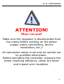
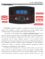
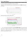
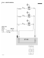
ST-85 – USER'S MANUAL
TECH
Declaration of Conformity No. 35/2010
Hereby, we declare under sole responsibility that the ST-85
230V 50Hz thermoregulator manufactured by TECH, ul. St.
Batorego 14, 34-120 Andrychów, is compliant with the
Regulation by the Ministry of Economy. (Journal of Laws
Dz.U. 155 Item 1089) of July 21, 2007 implementing
provisions of the Low Voltage Directive (LVD) 2006/95/EC
of January 16, 2007.
The
ST-85
controller
has
electromagnetic compatibility (EMC)
been
tested
for
with optimal loads
applied.
For compliance assessment, harmonized standards were
used:
PN-EN 60730-2-9:2006.
Co-owners:
Paweł Jura, Janusz Master
-2-
ST- 85 – USER'S MANUAL
ATTENTION!
HIGH
VOLTAGE!
Make sure the regulator is disconnected from
the mains before working on the power
supply (cable connections, device
installation, etc.)!
All connection works must only be carried out
by qualified electricians.
Before activating the controller, measure the
motor resetting efficiency, check the boiler
and inspect wire insulation.
-3-
Blow
ST- 85 – USER'S MANUAL
I. Description
Manual Mode
Blow
H.C.W. Pump
C.H. Pump
Exit
Standby
Encoder knob
The ST–85 temperature regulator is intended for use with central heating
boilers. The regulator is used for controlling the central heating water
circulation pump, hot consumption water pump and blow (fan).
The ST-85 is a PID-basedcontroller using a continuous signal. In this
type of controllers, the fan power is calculated based on boiler temperature
and flue gas temperature measured at the boiler outlet. The fan runs
continuously and its power depends directly on the measured boiler
temperature and flue gas temperature as well as the difference between the
two parameters and their setpoint values. Advantages of zPID regulators
include their ability to maintain a stable setpoint temperature without
unnecessary overregulations and oscillations.
By fitting the controller with a flue gas outlet sensor, you can save
from a few up to several percent of fuel, and ensure a steady water
temperature for a longer service life of your heat exchanger (boiler). Flue gas
outlet temperature monitoring ensures reduced harmful dust and
gas
-5-
ST-85 – USER'S MANUAL
emissions. The thermal energy from the flue gases is used for heating instead
of being wasted and disposed of through the funnel.
Research results presented below were obtained using the Tech PID-based
controller:
and the controller without PID control:
You can change all parameters with an encoder knob. Turning the knob
allows you to select a function or modify its value, while pressing the knob
allows you to enter the function or confirm changed values. To leave any
function, push the EXIT button.
-6-
ST- 85 – USER'S MANUAL
I.a) Basic Terms
Fire up. The cycle begins when you activate the fire up function in the
controller's menu and is active until the central heating boiler temperature
reaches
40oC
(the
default
fire-up
threshold),
on
condition
that
the
temperature does not drop below this value for 2 minutes (the default fire-up
time). If these conditions are met, the regulator will switch to the duty mode
and the manual operation symbol on the housing will be deactivated. If the
controller fails to reach parameters required for entering into the duty
mode within 30 minutes from activation of the fire-up function, the "Unable
to fire up" message will appear on the display. In such a case, the fire-up
cycle needs to be restarted.
Duty – once the fire-up cycle is finished, the controller enters the duty cycle.
The duty cycle is the basic functionality of the regulator. The blow is
controlled automatically using the zPID algorithm and the temperature is
close to its setpoint value. In the user menu, fan item will appear in place of
the fire-up function. The fan can be deactivated when needed (e.g. while
feeding fuel). If the temperature rises unexpectedly by more than 5 oC over
the setpoint value, the so-called Supervision Mode is activated.
Supervision Mode – the mode is activated during the Duty Cycle if the
temperature rises by more than 5oC over the setpoint value. In such case,
the controller is switched from the PID control to manual settings (according
to parameters entered in the Fitter’s Menu) to reduce the temperature of the
circulation water.
Damping – if boiler temperature drops by 2oC below the fire-up threshold
and fails to rise above this value for 30 minutes (default damping time), the
regulator will switch to thedamping mode. While in this mode, the fan is
deactivated and the display shows "Damping".
-7-
ST-85 – USER'S MANUAL
In case of voltage loss, the regulator ceases to operate. When power is
restored, the controller returns to operation with previously set parameters
using its built-in memory. Lack of voltage does not cause the stored
parameters to be lost.
II. Regulator Functionality
This chapter describes regulator functionality, how to change settings and
navigate in the menu with the encoder (knob). Depending on the mode the
boiler is currently in, the display will show boiler operational parameters. The
given mode is selected by the user.
II.a) Main Page
42 Oc
C.H.
|
55 Oc *
Setpoint
During normal operation, the LCD display shows the Main Page containing
the following:
● Boiler temperature (to the left of the display).
● Setpoint temperature (to the right of the display).
● Fan stop. After manually stopping the fan while in the duty mode, the star
symbol ( ) will appear in the down right corner.
● Operation Mode. In the up right corner, the corresponding letter of the
operation mode is displayed. Depending on the operation mode, the
corresponding symbol is displayed:
– house heating,
– water heater priority,
– parallel pumps,
– summer mode.
Pressing the encoder will move you to the main menu. The display
shows two options of the menu. To select a different option, turn the encoder
knob.
-8-
ST- 85 – USER'S MANUAL
II.b) Changing the central heating and hot consumption
water setpoint temperature.
In order to change the setpoint temperature of the central heating
(while in "C.H. screen" main view), turn the encoder knob and (after setting
a desired value) press it to confirm the change.
In order to change the setpoint temperature of the hot consumption
water (while in "H.C.W. screen" main view), turn the encoder knob and (after
setting a desired value) press it to confirm the change.
Chapter "Screen" describes methods of changing the main screen view.
II.c) Firing up
This function allows you to easily fire up the boiler. After igniting the
boiler, you need to activate an automatic fire-up cycle. By selecting optimum
parameters, the boiler uses the zPID function to smoothly switch to the duty
mode. If the boiler reaches the fire-up threshold temperature, the fan item
will appear instead of the fire-up function. From now on, the option will be
used to activate/deactivate the fan. This setting allows you to temporarily
deactivate the fan at any time, e.g. while feeding fuel.
If during the fire-up cycle the boiler does not reach 40 OC within 30
minutes, (default parameters), the following warning message will appear
on the display:
38 Oc
|
55 Oc
unable to fire up
To restore the boiler to operation, switch off the alarm by pressing the
encoder and restarting the fire-up procedure.
-9-
ST-85 – USER'S MANUAL
II.d) Manual Mode
42 Oc
C.H.
|
55 Oc
Setpoint *
For your convenience, the regulator features a manual mode module. In
this mode, each individual actuator is enabled and disabled independently of
the other. In addition to the Manual Mode function, the Blow Force
function has been provided.
Blow Force
Fan
20%
Blow Force
This function allows you to set the blow force of the fan while in the
Manual Mode.
Pressing the ENCODER activates the fan. The fan will operate until the
ENCODER is pressed again.
Blow Force
Fan
Press the ENCODER to enable / disable the central heating pump.
Fan
C.H. Pump
Press the ENCODER to enable / disable the (water heater) hot
consumption water pump.
C.H. Pump
H.C.W. Pump
Press the ENCODER to enable / disable the alarm.
H.C.W. Pump
Alarm
- 10 -
ST- 85 – USER'S MANUAL
II.e) Fuel Type
42 Oc
C.H.
|
Manual Mode
Fuel Type
55 Oc
Setpoint
Coal
Fines
This option allows you to select one of three fuel types (coal, fines
and
wood) for use in the boiler. Each fuel type has a fan operation mode assigned
to ensure the right burning process.
II.f) Central Heating Pump Activation
42 Oc
C.H.
|
Fuel Type
C.H. Pump Activation
55 Oc
Setpoint
35oc
C.H. Pump Activation
With this function, you can set the temperature that will activate the
central heating pump
(the temperature is measured on the boiler). The
pump will start if the setpoint temperature is exceeded. The pump will be
deactivated
when
the boiler
temperature
drops
below
the activation
temperature (minus hysteresis, e.g. 2OC). In this case, the pump will stop at
boiler temperature of 33OC.
II.g) H.C.W. Pump Activation
42 Oc
C.H.
|
55 Oc
Setpoint
C.H. Pump Activation
H.C.W. Pump Activation
40oc
H.C.W. Pump Activation
With this function, you can set the temperature that will activate the hot
consumption water pump
(the temperature is measured on the boiler).
Above the setpoint temperature (e.g. 40 OC), the pump is activated and
operates depending on the selected operation mode. The pump will be
deactivated
when
the boiler
temperature
drops
below
the activation
temperature (minus hysteresis, e.g. 3OC). In this case, the pump will stop at
boiler temperature of 37OC.
- 11 -
ST-85 – USER'S MANUAL
II.h) Operation Mode
42 Oc
C.H.
|
H.C.W. Pump Activation
Operation Mode
55 Oc
Setpoint
With this function, you can select one out of four operation modes.
II.h.1) House Heating
House Heating *
H.C.W. Priority
If you select this option, the regulator will switch to the house heating
mode. The central heating pump starts to run above the pump activation
temperature (set to 35OC by default). Below this temperature (minus central
heating hysteresis), the pump is shut off. While in the house heating mode,
the icon
is displayed in the up right corner of the main screen.
II.h.2) H.C.W. Priority
House Heating
H.C.W. Priority *
Activating the hot consumption water priority will cause the regulator to
switch into
consumption
the water heater priority mode. In this mode, the (hot
water)
heater
pump
is
activated
until
the
set
H.C.W.
temperature is reached. Then, the H.C.W. pump is shut off and the C.H.
pump is activated. The central heating pump will run until the water heater
temperature drops below the setpoint value (and the H.C.W. hysteresis);
then, the C.H. pump is shut off and the H.C.W. pump is activated.
In this mode, the fan is operated as long as the temperature is below 62°C
to prevent the boiler from overheating.
The
hot
consumption
water
priority
function
consists
in
that
consumption water is heated up before heating up water in radiators.
- 12 -
the
ST- 85 – USER'S MANUAL
While in the H.C.W. Priority mode, the icon
is displayed in the up right
corner of the main screen.
ATTENTION: The boiler should have non-return valves mounted on the
central heating pump circuit and the hot consumption water pump circuit. A
valve mounted on the hot consumption water pump will prevent hot
consumption water from being drawn from the water heater.
II.h.3) Parallel Pumps
H.C.W. Priority
Parallel Pumps *
42 Oc
C.H.
|
55 Oc
Setpoint
In this mode, the pumps start to run in parallel above the pump activation
temperature (set by default to 35OC). These temperatures may, however,
vary depending on user settings. This will cause irregular activation of the
pumps. However, when both thresholds are exceeded, the pumps will
operate simultaneously. The central heating pump runs continuously, while
the hot consumption water pump stops after the setpoint temperature is
reached in the water heater.
While in the Parallel Pumps mode, the icon
is displayed in the up right
corner of the main screen.
ATTENTION: In this mode, a non-return valve should be fitted to
maintain different temperatures in the water heater and in the house. After
activation of the parallel pumps function, three items appear on the display.
Starting from the left, these are: Boiler Temperature (C.H.); Water Heater
Temperature (H.C.W.) and Setpoint Temperature (C.H.).
II.h.4) Summer Mode
Parallel Pumps
Summer Mode *
45 Oc 43 Oc 55 Oc
C.H. H.C.W. Set
When the function is enabled, only the hot consumption water pump is
- 13 -
ST-85 – USER'S MANUAL
running in order to heat water in the water heater. The pump is switched on
above
a
predefined
activation
threshold
(see
the
pump
activation
temperature function) and will run until the setpoint temperature has been
reached. The pump will start again when the temperature drops below the set
hysteresis. In the Summer Mode, only the setpoint temperature is set on the
boiler that heats up water for the water heater (the temperature set for the
boiler is also the temperature set for the water heater).
While in the Summer Mode, the icon
is displayed in the up right corner
of the main screen.
II.i) Main Screen
OPERATION MODE
MAIN SCREEN
This function allows you to change the view of the main screen. The
following views are available:
➢ C.H. SCREEN
• C.H. SCREEN
H.C.W. SCREEN
44 Oc
C.H.
|
55 Oc
Setpoint
This screen displays the current and setpoint C.H. temperatures. By
turning the knob, you can change the setpoint temperature. After setting the
appropriate value, confirm it by pressing the encoder knob.
➢ H.C.W. SCREEN
C.H. SCREEN
• H.C.W. SCREEN
43 Oc
H.C.W.
|
50 Oc
Setpoint
This screen displays the current and setpoint H.C.W. temperatures. By
turning the knob, you can change the setpoint H.C.W. temperature. After
- 14 -
ST- 85 – USER'S MANUAL
setting the appropriate value, confirm it by pressing the encoder knob.
➢ FLUE GASES SCREEN
H.C.W. SCREEN
• FLUE GASES SCREEN
45 Oc 93 Oc 80%
C.H. FLUE FAN
The following items are displayed, starting from the left: current C.H.
temperature, current flue gases temperature and blow power in percentages.
This view is used for monitoring current boiler parameters.
II.j) Language
MAIN SCREEN
LANGUAGE
With this function, you can select the language of your controller.
II.k) Factory Settings
23 Oc
|
55 Oc
Setpoint
Fixed C.H. Pump
Factory Settings
Yes
No
The regulator has been pre-configured. However, it should be adjusted to
your individual needs. It is possible to return to the factory settings at any
time. By enabling the Factory Settings, all existing boiler settings will be
replaced by settings made by the manufacturer. From then on, you can again
set your own operating parameters for the boiler.
II.l) Fitting parameters
Access to fitting parameters is disabled for the user. This special view
contains advanced parameters accessible only by the manufacturer.
- 15 -
ST-85 – USER'S MANUAL
III. Protections
In order to ensure a safe and faultless operation, the regulator has been
provided with numerous protections. In the case of an alarm, an acoustic
warning is sounded and the display shows a corresponding message.
Press the encoder to restore the controller to operation. In the case of the
C.H. Temperature Too High alarm, wait until the temperature drops below
the alarm value.
III.a) Thermal protection
The boiler is protected with an additional bimetal sensor (located at the
boiler temperature sensor) that disables the fan when the temperature
exceeds the critical value: 85 OC. This is to prevent water from boiling in the
system when the boiler has been overheated or the controller is damaged.
When the protective function is enabled and the temperature drops to a safe
value, the sensor will automatically restart the device and the alarm will be
deactivated. If the sensor is damaged or overheated, the burner, fan and
feeder are disabled.
III.b) Automatic Sensor Check
When the temperature sensor of the central heating or hot consumption
water is damaged, an alarm is sounded with an additional indication shown in
the display, e.g.: „C.H. Sensor Damaged".
Alarm
C.H. Sensor Damaged
Blow is disabled and both pumps are activated simultaneously, regardless of
the temperature.
If the central heating sensor is damaged, the alarm will remain active until
the sensor is replaced. If the hot consumption water sensor is damaged,
pressMENU to deactivate the alarm and restore the single (house heating)
- 16 -
ST- 85 – USER'S MANUAL
pump mode. To be able to operate the boiler in all modes, it is necessary to
replace the sensor.
III.c) Temperature Protection
The regulator features an additional protection in case the bimetal sensor
is damaged. After the temperature exceeds 85 OC, the alarm is sounded with
the display showing the following message:
Alarm
Temperature Too
High
The current temperature is read from an electronic sensor
and
processed by the thermoregulator. When the alarm temperature is exceeded,
the fan is shut off and both pumps begin to run in order to distribute hot
consumption water throughout the system.
III.d) Anti-Boil Protection
This protective function is used only with the water heater priority
mode. For example, when the water heater setpoint temperature is 55 OC and
the boiler temperature rises to 67OC (5OC over the so-called priority
temperature), the controller shuts off the fan.If the boiler temperature
reaches 80OC, the C.H. pump will be activated. If the temperature continues
to rise, the alarm will be activated at 85 OC. Such condition may appear when
the water heater or the pump is damaged or when the sensor has been
improperly installed. However, if the temperature drops, the controller will
activate the fan at 66OC and it will remain in the duty mode maintaining the
priority temperature of 62OC.
- 17 -
ST-85 – USER'S MANUAL
III.e) Monitoring the flue gas outlet temperature
23 Oc
C.H.
98 Oc
Flue
50%
Fan D
This sensor constantly monitors the flue gas outlet temperature. If the
sensor is damaged, disconnected from the controller or removed from the
flue conduit, Flue Gas Sensor Damaged massage will appear on the
display. This will cause the controller to switch to the emergency mode. In
such case, only boiler temperature is used. The controller is operated using
only the boiler sensor and the zPID function remains active without the flue
gas outlet sensor.
III.f) Fuse
The regulator has a network protection WT 3.15 A tube fuse. Higher
current ratings may cause damage to the controller.
IV. Maintenance
Before and during the heating season, the ST-85 controller should be
checked for condition of its cables. You should also check if the controller is
properly mounted and clean it if dusty or dirty. It is advisable to measure
grounding
parameters
for
the
consumption water pump and fan)
- 18 -
motors
(central
heating
pump,
hot
ST- 85 – USER'S MANUAL
ST-85 Technical Specifications
No. Specification
Unit
1
Supply Voltage
V
230V/50Hz +/-10%
2
Power consumption
W
5
3
Ambient temperature
O
4
Circulation pump outlet load
A
0,5
5
Fan outlet load
A
0,6
6
Temperature measurement range
O
C
0÷90
7
Measurement accuracy
O
C
1
8
Sensor thermal resistance
O
C
-25÷90
9
Fuse insert
A
C
5÷50
3,15
V. Assembly
ATTENTION: all assembly works must only be carried out by qualified
persons. During assembly, the device must be disconnected (make sure the
power cord is unplugged)!
ATTENTION: improper cable connections may damage the regulator!
The regulator may not be operated in a closed-circuit central heating
system. It is necessary to provide for safety valves, pressure valves and a
surge tank in order to prevent water from boiling in the central heating
system.
V.a) Cable Connection Diagram for Controller
Pay special attention to cable connections during assembly. Especially, the
ground wire should be connected properly.
- 19 -
ST-85 – USER'S MANUAL
- 20 -
ST- 85 – USER'S MANUAL
We are committed to protecting the environment. Manufacturing electronic devices
imposes an obligation of providing for environmentally safe disposal of used electronic
components and devices. Hence, we have been entered into a register kept by the
Inspection For Environmental Protection. The crossed-out bin symbol on a product means
that the product may not be disposed of to household waste containers. Recycling of
wastes helps to protect the environment. The user is obliged to transfer their used
equipment to a collection point where all electric and electronic components will be
recycled.
- 21 -
ST-85 – USER'S MANUAL
Table of Contents
I. Description....................................................................................... 5
II. Regulator Functionality...................................................................... 8
II.a) Main Page.................................................................................. 8
II.b) Changing the central heating and hot consumption water setpoint
temperature...................................................................................... 9
II.c) Firing up.................................................................................... 9
II.d) Manual Mode............................................................................ 10
II.e) Fuel Type................................................................................. 11
II.f) Central Heating Pump Activation..................................................11
II.g) H.C.W. Pump Activation............................................................11
II.h) Operation Mode......................................................................... 12
II.h.1) House Heating.....................................................................12
II.h.2) H.C.W. Priority.................................................................... 12
II.h.3) Parallel Pumps.....................................................................13
II.h.4) Summer Mode.....................................................................13
II.i) Main Screen............................................................................... 14
II.j) Language.................................................................................. 15
II.k) Factory Settings........................................................................ 15
II.l) Fitting parameters...................................................................... 15
III. Protections.................................................................................... 16
III.a) Thermal protection...................................................................16
III.b) Automatic Sensor Check............................................................16
III.c) Temperature Protection.............................................................17
III.d) Anti-Boil Protection...................................................................17
III.e) Monitoring the flue gas outlet temperature..................................18
III.f) Fuse........................................................................................ 18
IV. Maintenance.................................................................................. 18
V. Assembly........................................................................................ 19
V.a) Cable Connection Diagram for Controller.......................................20
- 22 -
ST- 85 – USER'S MANUAL
- 23 -
ST- 85 – USER'S MANUAL
- 24 -


![Manuel d`utilisation Régulation TECH ST3[...]](http://vs1.manualzilla.com/store/data/006377962_1-761c4fa99f631e7c2b8551b5818edead-150x150.png)