1
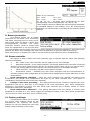
TECH TECH Declaration of conformity 61/2012 Hereby, we declare under our sole responsibility that ST-450zPID 230V, 50Hz thermoregulator manufactured by TECH, headquartered in Wieprz 1047A, 34-122 Wieprz, is compliant with: the regulation by the Ministry of Economy, Labour and Social Policy (Journal of Laws No. 155, Item 1089) of August 21, 2007 implementing provisions of the Low Voltage Directive (LVD) 2006/95/EC, an act of April 13, 2007 concerning Electromagnetic Compatibility (Journal of Laws 07.82.556) implementing provisions of EMC directive 2004/108/EC, the regulation by the Ministry of Economy of May 8, 2013 concerning the essential requirements as regards the restriction of the use of certain hazardous substances in electrical and electronic equipment, implementing provisions of RoHS directive 2011/65/EU. For compliance assessment, harmonized standards were used: PN-EN 60730-2-9:2011, PN-EN 60730-1:2012 Date of CE marking : 08-2012 Wieprz, 15. 12. 2014 2 ST-450zPID I. Safety Before using the device for the first time the user should read the following regulations carefully. Not obeying the rules included in this manual may lead to personal injuries or controller damage. The user’s manual should be stored in a safe place for further reference. In order to avoid accidents and errors it should be ensured that every person using the device has familiarized themselves with the principle of operation as well as security functions of the controller. If the device is to be sold or put in a different place, make sure that the user’s manual is there with the device so that any potential user has access to essential information about the device. The manufacturer does not accept responsibility for any injuries or damage resulting from negligence; therefore, users are obliged to take the necessary safety measures listed in this manual to protect their lives and property. ! WARNING High voltage! Make sure the regulator is disconnected from the mains before performing any activities involving the power supply (plugging cables, installing the device etc.) The device should be installed by a qualified electrician. Before starting the controller, the user shoud measure earthing resistance of the electric motors as well as the insulation resistance of the cables. The regulator should not be operated by children. ! WARNING The device may be damaged if struck by a lightning. Make sure the plug is disconnected from the power supply during storm. Any use other than specified by the manufacturer is forbidden. Before and during the heating season, the controller should be checked for condition of its cables. The user should also check if the controller is properly mounted and clean it if dusty or dirty. 3 TECH II. Description Temperature controller ST–450 zPID is intended for use with central heating boilers equipped with feeding screw. It controls water circulation pump, domestic hot water pump, floor heating pump, circulation pump, blower (fan) and fuel feeder. It incorporates a valve control module and can operate with two mixing valves (via additional ST-61 modules), conventional (two-state) room controller or RSport communication, GSM module or Ethernet module. The advantage of the controller is the ease of use. The user can change all parameters using a pulser knob. Another advantage is a large and easy-to-read display where the current boiler operation is shown. Exemplary view of the main screen: Pump operation mode Clock, flue gas temperature Current boiler temperature Current DHW temperature Set-point boiler temperature Set-point DHW temperature Feeder, Fan, Pumps: CH, DHW, circulating or valve, valve calibration Exit Pulser knob STANDBY mode The ST-450zPID controller is a regulator with a continuous output signal utilizing the PID regulation algorithm. In this type of controller the blow-in power is calculated on the basis of the measurement of the temperature of the boiler and the temperature of flue gas measured on the outlet of the boiler. Operation of the fan proceeds on an ongoing basis and the blow-in power depends directly than the measured boiler temperature, the temperature of flue gas and the difference of these parameters from their preset values. Stable maintenance of the set temperature without any unnecessary adjustments and oscillations is the advantage of a regulator with PID. When using this type of controller with a flue gas outlet sensor, savings in fuel combustion may reach up to more than ten percent; The outlet water temperature is very stable, which affects the longer life span of the exchanger (boiler). Checking the temperature of flue gas at the outlet from the boiler causes low emission of dusts and gases harmful for the environment. Thermal energy from the flue gas is not wasted and released to the chimney, but used for heating. Below we present the results of tests conducted with the use of the Tech controller with PID control: 4 ST-450zPID and the same controller without PID control: Any comments concerning the program should be reported to the boiler's manufacturer. Each controller should be set individually for personal needs, depending on the type of fuel used for burning as well as the type of the boiler. The TECH company shall not be liable for any incorrect settings of the controller. a) Basic terms Firing – The cycle starts after the flue gas temperature has reached the defined value provided that it does not drop below that level for a period of 30 seconds (factory-set firing time). Operation – After completion of firing cycle the controller enters the operation cycle and a message reading “PID:OPERATION” appears on the display. It is the basic operation status of the controller where the blowing operation and fuel feeding are performed automatically following the PID algorithm and the temperature is fluctuating around the temperature preset by the user. Should the temperature rise unexpectedly 5°C above the pre-set value a so-called supervision mode is activated. Supervision mode– It is activated automatically if the temperature exceeds the pre-set value by more than 5°C in the operation mode. In such a case the controller changes PID operation to manual settings (according to parameters stored in the installation menu >> Supervision mode) to reduce the circulation water temperature and a message “PID:SUPERVISION” appears in the display. Damping – If the flue gas temperature drops below the predefined value and does not rise above that level for a period of 300 seconds (factory-set damping time) the controller enters the damping mode. When in that mode both blower and feeder are stopped and the display reads “PID:DAMPED””. III. Functions of the regulator This chapter describes the functions of the regulator, the method of changing the settings as well as navigation in the menu which is made using the pulse generator (knob). The boiler's operational parameters are displayed on the main screen of the controller. The user selects the operation mode and a number of settings of the boiler according to their own needs. b) Homepage During normal operation of the regulator, the main page is visible on the graphic display. Depending on the operation mode, one of the following screens is displayed. Pressing the knob of the pulse generator brings the user to the first level menu. The first three menu options are shown on the display. Turn the knob to move to subsequent options. Press the knob to select a given function. Similar actions are made when changing parameters. To introduce changes it is necessary to approve them by pressing the pulse generator when the APPROVE message is shown. If the user does not want to make any changes in a given function, they should press the pulse generator when the CANCEL message is shown. To exit the menu select the exit option. If necessary, you can use the standby mode button located on the controller housing to rapidly turn off all actuators. This is an additional safeguard feature for use in an emergency situation that allows you to power down all controller actuators (fan, pump, valve). NOTE: Power is not disconnected from the controller when it is in standby mode. 5 TECH b) Screen view You can use this function to select one of four thermoregulator operation main screens: CH screen (displays the current mode of operation of the boiler) main valve (displays the operating parameters of the main valve) valve 1 (displays the operating parameters of additional valve 1). valve 2 (displays the operating parameters of additional valve 2). NOTE: To enable the views showing valve parameters the respective valves must be pre-installed and configured properly by a installation fitter. c) Firing This function helps to fire the boiler easily. After initiation of fire the user will start the automatic firing cycle. Selection of optimum working parameters will allow the boiler to enter the operation mode smoothly by using the PID function. d) Preset temperature of the central heating system The option is used to set the boiler temperature. The user can change the boiler temperature within the range of 45ºC to 80ºC. The preset central heating system temperature can also be changed directly in the main screen of the controller by turning the pulser knob. Additionally, the preset central heating system temperature can be adjusted using the room temperature reduction function and the weekly control function. The preset temperature is a sum of all those values but it may not exceed the range of 45ºC to 80ºC. e) Set-point DHW temperature This function allows you to set your required set-point temperature for domestic hot water. You can adjust this temperature within a range from 40⁰C to 75⁰C. f) Manual operation For the user's convenience, the regulator has been equipped with a Manual operation module. In this function, each executive device (the feeder, the blow-in, the CH pump, the HUW pump, the circulation pump and the floor pump) is activated and deactivated independently of the others. Pressing the pulse generato activates the engine of the chosen device. This device remains activated until the pulse generator is pressed again. The blow-in power, where the user has the possibility to set any rotational speed of the fan in manual operation, is additionally available. g) Operation mode In this function, the user selects one of four options of the boiler's operation. 6 ST-450zPID House heating When you select this option the controller switches over to a mode where heating is provided only to heat the central heating circuit. The central heating pump begins to run above the pump activation temperature (factory set at 38⁰C). The pump will turn off below this temperature (minus a hysteresis of 2°C. Boiler tank priority In this mode, the boiler tank (hot water) pump will be switched on first to run until the set-point temperature is reached (see Section II.e), after which the pump will be turned off and the CH circulating pump will be enabled. The central heating pump will run all the time until the boiler tank temperature drops below its set-point by the hot water hysteresis value. At that moment the CH pump will turn off and the HW pump will turn on (both pumps operating alternately). In this mode the fan and the feeder are run only up to 62OC as measured at the boiler (instantaneous set-point) so as to prevent overheating of the boiler. NOTE: The boiler must be fitted with check valves on the central heating and hot water pump circuits. The valve mounted on the hot water pump is to prevent drawing hot water from the boiler tank. Pumps in parallel In this mode both pumps begin to run together (in parallel) above the pump activation temperature. However, these temperatures may vary for each pump, depending on your settings. When this is so one of the pumps will switch on earlier than the other one, but after both thresholds are crossed both pumps will run together. The central heating pump will run all the time while the hot water pump will turn off when the boiler tank set-point temperature is reached. It will turn on again when the temperature drops by the preset HW hysteresis value below its set-point. Summer mode Once this function is activated the central heating pump will be off and the DHW pump will turn on above the preset activation temperature (see Section III.h) and will work continuously until the temperature drops below the activation temperature by the hot water hysteresis value or until the following conditions are met: (boiler temperature) + 2°C ≤ (boiler tank temperature) In summer mode you only enter the set-point temperature of the boiler, which is also understood to mean the set-point temperature of the boiler tank. h) Weekly control The function is used to programme daily changes in the boiler temperature. The preset temperature deviations are within the range of +/-10⁰C. Step #1: The user needs to set current time and date first (Installer menu > Clock). Step #2: The user sets temperature values for individual days of the week (Set mode 1): Monday– Sunday Select specific hours and required deviations from the preset temperature (how many degrees the temperature should rise or drop) for each day of the week. Additionally, the preset values can be copied to facilitate the operation. Example Monday preset: 3 00 , temp. -100C (temperature change– 100C) 7 TECH preset: 4 00 , temp. -100C (temperature change – 100C) preset: 5 00 , temp. -100C (temperature change – 100C) In such a case, if the temperature preset on the boiler is 60ºC, it will drop 10ºC to 50ºC between 3 a.m. and 6 a.m. on Monday. As an alternative to the temperatures being preset separately for individual days, the temperatures can also be set collectively, in the second mode, for the working days (from Monday to Friday) and the weekend (Saturday and Sunday) separately - Set mode 2. Monday - Friday; Saturday - Sunday Similarly to the previous mode it is necessary to select specific times and required deviations from the temperature preset for the working days (Monday - Friday) and the weekend (Saturday, Sunday). Example Monday - Friday preset: 3 00 , temp. -100C (temperature change – 100C) preset: 4 00 , temp. -100C (temperature change – 100C) preset: 5 00 , temp. -100C (temperature change – 100C) Saturday - Sunday preset: 16 00 , temp. 50C (temperature change +50C) preset: 17 00 , temp. 50C (temperature change +50C) preset: 18 00 , temp. 50C (temperature change +50C) In this case, if the preset boiler temperature is 60ºC, the temperature will drop 10ºC to 50ºC between 3 a.m. and 6 a.m. on each day from Monday to Friday. However, the temperature will rise 5ºC to 65ºC during weekend (Saturday, Sunday) between 4 p.m. and 7 p.m. Step #3: The user enables one of two preset modes (Mode1, Mode2) or disables the weekly control option. Once the mode is enabled the value of the deviation currently set is displayed on the main page of the controller next to the preset central heating system temperature. This, additionally, indicates that the weekly control is active. Data deletion function is a simple method to remove all previously saved weekly programme settings to enter new settings. i) Fuel size This option is used to select one of two fuel sizes: coarse or fine. Appropriate blowing power and fuel supply rate are selected for each of the sizes. j) Room temperature reduction After the room controller reaches the preset room temperature, the preset boiler temperature (set in the installation menu - see Item III.16) will drop by the value set there. The reduced temperature will not be lower however than the preset minimum central heating temperature. Example: Temperature preset on the boiler: 55ºC Room temperature reduction: 15ºC Minimum temperature set on the boiler: 45ºC (factory setting) Once the preset room temperature is reached (indicated by the room controller) the temperature preset on the boiler will drop to 45ºC i.e. only 10ºC although the room temperature reduction is 15ºC. At the same time a message reading "!-10º" will be shown in the main display next to the preset boiler temperature. k) Factory settings The controller is pre-configured for its operation. However, its settings should be modified to meet your individual needs. You can return to the factory settings at any time. If you enable the factory settings option you will lose all of your own boiler settings, which will replaced with the settings saved by the boiler manufacturer. From now on you can re-set your own parameters of the boiler. l) About the program You can use this function to check the software version installed in the boiler controller. 8 ST-450zPID IV. Installation menu The functions of the installation menu should be set by the person installing the boiler or service personnel of the manufacturer. a Fan coefficient This function is used to control the fan power. The control is based on shifting the fan performance curve up or down. If the blowing rate in the whole control range is too low/high, the coefficient should be increased/decreased accordingly to ensure proper efficiency of the fan operation. Malfunctioning of the blowing system is most frequently caused by relatively large differences between voltages supplied to individual units, which has a significant impact on the fan operation. c) Feeding coefficient Fuel feeding coefficient is intended to optimize the feeder operation so as to ensure that fuel is fed to the furnace in proper quantities. This function allows setting the percentage increase or decrease of fuel being supplied. Once the proper fuel size is selected in the main menu it is possible, by using the coefficient, to adapt precisely the fuel quantity to be fed by the feeder to the furnace. d) TECH controller A room controller can be connected to ST-450zPID controller. This function allows configuring the controller by selecting “ON” option. Additionally, the user may check the programme version of the room controller. After connection of TECH controller the user may check and change the preset temperature of the central heating system, hot domestic water and the mixing valve. Additionally all boiler controller alarms are displayed. When the operation involves the mixing valve the user may preview the current external temperature while viewing the main screen with the valve parameters. After TECH Controller option is enabled a letter "P" appears in the upper part of the display in the main screen of the controller. A flashing letter "P" indicates that the temperature in the room is too low. As soon as the required room temperature is reached the letter "P" stops flashing and stays on. ATTENTION: No external voltage can be connected to the room controller output. e) Valve ST-450zPID controller incorporates a mixing valve control module. The below options are used to set the operation of the mixing valve. 1. Valve state The function allows disabling the valve temporarily without the need to remove it completely. Once it is re-enabled no registration is required. 2. Set-point valve temperature This setting is used to set the circuit temperature to be maintained by the mixing valve. This is the main temperature based on which the room thermostat reduction function is to be run. The room thermostat reduction function is set separately for the CH system (setting in the user menu) and separately for each of the valves. 9 TECH 3. Temperature control This parameter determines the sampling (control) frequency of the water temperature downstream of the valve for the central heating or hot water system. If the sensor indicates a change in temperature (deviation from set-point), then the solenoid will open or close partially by a preset step to restore the set-point temperature. 4. Opening time You can use this function to set the time for the full opening of the valve, that is to say, how long it takes to open the valve to 100%. This time should be selected according to your valve actuator (shown on the nameplate). 5. Single step You can use this function to set a percentage value for a single step in the operation of valve opening, that is to say the maximum percentage value of opening or closing that the valve can move in a single step (maximum movement of the valve in one measurement cycle). 6. Minimum opening Use this function to set the minimum value for valve opening. Below this value, the valve will not close shut. 7. Type of valve You can use this option to select the type of valve: central heating or floor type. 8. Weather program (weekly valve program) In order to enable the weather function an outdoor sensor should be installed in a place not exposed directly to sunlight or weather conditions. After installing and connecting the sensor the Weather program function must be enabled in the controller menu. For the valve to work properly enter set-point temperatures (downstream of the valve) for the following four intermediate outside temperatures: TEMP. FOR -20 TEMP. FOR -10 TEMP. FOR 0 TEMP. FOR 10 Heating curve - curve which is used to determine the set-point temperature of the controller based on the outside temperature. In our controller this curve is established based on four temperature set-points selected for their respective outside temperatures. Set-point temperatures must be provided for the following outside temperatures: -20ºC, -10ºC, 0ºC and 10ºC 10 ST-450zPID Where in our controller: XA = -20ºC, XC = 0ºC, XB = -10ºC, XD = 10ºC, YA, YB, YC, YD – set-point valve temperatures for their corresponding outside temperatures: XA, XB, XC, XD After weather control is enabled the valve set-point parameter is calculated based on the heating curve. By changing this parameter you can decrease or increase all the weather control settings. 9. Return protection This feature allows you to enable protection for the boiler from excessively cold water returning from the main circuit, which could cause the boiler to suffer from low-temperature corrosion. The return protection function works to ensure that when the temperature is too low the valve will close partially until the short circuit of the boiler reaches the desired temperature. This feature also protects the boiler from a dangerously high return temperature to prevent water from boiling. When this function is enabled you need to set the minimum and maximum return temperatures. 10. Room controller The option is used to define the room controller type to operate with the valve. The following options are available: Off – State of the room controller has no impact on the valve settings. Standard controller – A two-state controller. This setting applies to the controller connected directly to the valve control module (ST-61) for external valves (valve 1 & 2). For internal valve, in turn, the setting applies to the controller connected directly to ST-450zPID controller. TECH controller– Controller with RS communication function. Proportional control – Available only with TECH controllers with RS communication. It operates properly after configuration of the preset valve change option and the difference in room temperatures. Room temperature reduction – Once the room controller has reached the preset room temperature, the preset valve temperature will drop by the value indicated here. (The option is unavailable if Proportional control has been selected). Change of the valve presetting – The setting determines the number of degrees the valve temperature will rise or drop with a unit change of the room temperature (see: Room temperature difference). The function is active only with TECH room controller and is directly related to “Room temperature difference” parameter. Room temperature difference – The setting determines the unit change in current room temperature (accurate to 0.1°C) which triggers the predefined change in the valve preset temperature (The function is active with TECH room controller only). 11. Factory settings This parameter allows you to restore the mixing valve settings saved by the manufacturer. By restoring the factory settings you will not change the valve type setting (central heating or floor type). 11 TECH f) Valve 1 NOTE: Control with an additional valve (1 or 2) is only possible after you purchase and connect the controller to an additional control module (ST-61), which is not provided as standard equipment with the controller. In order to control two valves you need to connect two ST-61 modules. The options presented in this chapter are used to adjust the operating settings of an additional mixing valve. In order for the valve to work properly and meet your expectations it should be configured with its parameters set like in the case of the main valve. 1. Registration To register an additional valve enter the serial number of the control module of the ST-61 mixing valve servo (look for the five-digit number on the cover of this module). Without this number the valve cannot be activated. 2. Switch on Setting as for the main valve 3. Set-point valve temperature Setting as for the main valve 4. Temperature control Setting as for the main valve 5. Opening time Setting as for the main valve 6. Single step Setting as for the main valve 7. Minimum opening Setting as for the main valve 8. Type of valve Setting as for the main valve 9. Weather program (weather control) Setting as for the main valve 10. Return protection Setting as for the main valve. 11. Additional sensors When two mixing valves are used and you select this function you will be able to select the sensors from which temperature data are to be retrieved for a valve (for return and outside temperature sensors). Temperatures can be retrieved from the sensors of the valve being set (Own) or as per the controller sensors (Main controller). 12. Room thermostat reduction Setting as for the main valve 13. Factory settings Setting as for the main valve 14. Valve removal This function is used to completely remove a valve from the controller memory. Valve removal is used for example when removing or replacing a module (the new module requires to be registered again). 15. About the program When this option is selected the display will show the software version of the active valve module. 12 ST-450zPID g) Valve 2 All settings for valve 2 are made in the same way as in the case of valve 1. h) GSM module NOTE: Controlling of this type is possible after purchasing and connecting, to the controller, the additional control module ST65 which is not attached to the regulator as a standard feature. The GSM module is an optional device cooperating with the boiler controller, enabling remote control of the boiler operation with the use of a mobile phone. The User is notified with a text message on each alert of the boiler controller, and by sending an appropriate text message at any time, he or she receives a return message with the information on the current temperature of all sensors. After entering an authentication code it is also possible to remotely change the set temperatures. The GSM module can also operate independently from the boiler controller. It has two inputs with temperature sensors, single contact input for use in any configuration (detecting short circuit/opening of contacts) and one controlled output (e.g. possibility to connect additional contactor to control any electrical circuit). When any temperature sensor reaches the preset deactivation temperature, maximum or minimum, the module will automatically send a text message with such information. It is similar in the case of a short-circuit or opening of contact input, which may be used e.g. for simple protection of property. If ST-450 controller is equipped with an additional GSM module, in order to activate this device, it is required to start the activated option (MENU> Installer menu> GSM module> Activated). i) Internet module NOTE: Controlling of this type is possible after purchasing and connecting, to the controller, the additional control module ST500 which is not attached to the regulator as a standard feature. The Internet module is a device enabling remote control of the boiler over the Internet or local network . On the home computer screen the user controls the condition of all boiler system devices and the operation of each device is presented in the animated form. Apart from the possibility to view the temperature of every sensor, the user has the possibility of introducing changes of the set temperatures for both the pumps and the mixing valves. After activating the Internet module and selecting the DHCP option, the controller will automatically download such parameters from the local network as: IP address, IP Mask, Gateway address and DNS Address. In the case of any problems with downloading network parameters of the existing network, there is a possibility of setting these parameters manually. The method of obtaining local network parameters has been described in the instructions for the Internet module. The function Reset module password may be used when the User, on the login page, has changed the factory user's password to his or her password. When a new password is lost, it is possible to return to the factory password after resetting the module password. j) Pump activation temperature The option is used to set the activation temperature for central heating and domestic hot water pumps (the temperature is measured on the boiler). None of the pumps will operate if the temperature is lower than the preset one. If the actual temperature is higher than the preset one the pumps are working but they operate depending on the operation mode (see: pump operation modes). 13 TECH k) DHW hysteresis Use this option to set your set-point temperature hysteresis at the boiler tank. This is the maximum difference between the set-point temperature (your required temperature for the boiler tank when the pump turns off) and the temperature when its operation is to resume. Example: The set-point temperature is 55°C and the hysteresis value is 5oC. After the set-point temperature (i.e. 55⁰C) is reached the hot water pump will turn off causing the central heating pump to turn on. The hot water pump will be switched on again when the temperature drops back to 50⁰C. l) Feeder in auto mode The option allows the automatic operation of the feeder to be enabled or disabled. The feeder can be disabled to feed fuel manually or to shut the boiler down. m) Blowing in auto mode Automatic operation of the fan can be enabled or disabled using this function. Blowing can be disabled to manually control the natural chimney draught. n) Floor pump The function is used to control the floor heating. The user sets the floor heating temperature in the range between 30ºC to 55ºC. After activation of the floor pump the minimum activation (threshold) temperature (measured on the boiler) and the maximum (preset) temperature of the floor heating (measured on the pump sensor) should be set. The floor pump will not operate below the minimum temperature. It turns on after the minimum temperature is exceeded until the preset maximum temperature is reached. Once the preset temperature is reached the pump turns off and it is restarted if the temperature drops 2ºC below the pre-set value. o) Circulation pump The function allows controlling the pump which is used to mix hot water between the boiler and the domestic hot water taps. After the function is activated the user sets the 24h activation cycle or pause cycle accurate to 30 minutes. To facilitate the 24h operation and pause cycle setting it is possible to copy the selected time interval to another interval. After the operation schedule has been set it is necessary to set the working and pause times for the pump while the previously selected time period is active. If necessary the previous settings can be easily deleted to facilitate setting of new intervals. p) Clock You can use the clock settings to enter the current time and day of the week. q) Date setting The function is used to set current date (day and month). r) Pulser sensitivity With this setting you can change the sensitivity of the pulser knob within a range from 1 to 3 (where 1 means the highest sensitivity). s) Language choice The user can choose the language version of the controller. 14 ST-450zPID t) PID selection After the PID control function is disabled the controller will operate as a normal two-state controller and the below listed additional functions will appear in the main menu: Feeding time This option is used to set the fuel feeder operation time. The time should be set according to the fuel being used and the boiler type; Feeding pause Feeding pause time is used to set the pause time in feeder operation. The pause length should be adapted to the fuel type combusted in the boiler. Wrong selection of operation and/or pause times may result in boiler malfunctioning i.e. the fuel may be not fully combusted or the boiler may not reach the preset temperature. Selection of appropriate times will ensure proper operation of the boiler; Temperature alarm This function is used to set the time after which the temperature alarm is activated. If the preset boiler temperature is not reached within the set time, the alarm will go off. The alarm is disabled by pressing the pulser knob. Once the alarm is disabled the controller will return to the most recent operation mode. Blowing rate The function controls the operating speed of the fan. The adjustment range is between 1 and 100% (equivalent to fan speeds). The higher the speed is, the faster the fan operates, where 1% stands for the minimum fan speed and 100% is the maximum speed. Sustained operation This function is used to set the fuel feeding time when in sustain mode (operation above the preset temperature). This prevents the boiler from damping if the actual temperature is higher than the preset one. ATTENTION: Wrong setting may cause constant temperature increase. Sustain pause This function is used to set the pause time in fuel feeder operation when in the sustain mode. ATTENTION: Wrong setting may cause constant temperature increase! The sustain pause should not be too short. Fan in sustain mode The function allows the user to select working and pause times during fan operation in the sustain cycle. Boiler hysteresis This option is used to set the hysteresis of the preset temperature. It is a difference between the sustain cycle activation temperature and the temperature to return to operation cycle (e.g. if the preset temperature is 60°C with hysteresis equal to 3°C, switching to sustain mode is performed after the temperature of 60°C is reached, and the device returns to operation cycle once the temperature drops to 57°C). Once the controller operation without PID is selected the following functions (assigned to PID only) will disappear from the main and installation menus: firing, damping boiler power, air correction, fuel type, supervision mode. u) Room controller This function is used to define the type of the controller connected to ST-450 controller with PID and programme the room controller operation: 15 TECH Off – no room controller connected; Standard controller – two-state room controller; TECH controller – controller with RS communication function. Room controller unit Off – state of the room controller has no impact on other settings Boiler – once the room controller indicates that the preset temperature has been reached the temperature preset on the boiler will be reduced Central heating pump - once the room controller indicates that the preset temperature has been reached the central heating pump will be turned off After TECH Controller or standard option is enabled a letter "P" appears in the upper part of the display in the main screen of the controller. A flashing letter "P" indicates that the temperature in the room is too low. As soon as the required room temperature is reached the letter "P" stops flashing and stays on. Information about the programme – This function allows the user to check the programme version of the TECH room controller connected. v) Display contrast Allows changing the display contrast settings. V. Service Menu To access the servicing functions of the ST-450 controller you must enter a four-digit code. This code is known to the boiler manufacturer and the company Tech. VI. ST-66 Pellet module ST-450zPID controller may optionally be used to control a pellet boiler via an additional ST-66P module. In the case of pellet boilers, it is possible to remotely initiate both the fire-up and the damping phase via a telephone (an additional GSM module (ST-65) must be connected to the controller). Certain function of the controller are changed: a) Fire-up In the case of ST-450zPID controller with ST-66P module, the fire-up process is automated and it is carried out with the use of a heater. After the furnace is cleared, the user initiates the fire-up process in the controller. The first portion of fuel is fed to the furnace followed by activation of the fan and the heater. The heater operates until the flue gas temperature increases by 10ºC and it is disabled. When the flue gas outlet temperature reaches the threshold value of 55oC, the controller enters operation mode. When the flue gas temperature does not reach the fire-up temperature within 10 minutes from the heater deactivation, the heater is enabled and operates until the flue gas outlet temperature reaches at least 50oC (but no longer than 20 minutes from the initial fuel feeding). If the flue gas temperature does not reach the temperature of 50ºC, the display informs about the fire-up failure. In such a case, the fire-up should be started again after the furnace is cleared. When the fire-up fails, the controller should be switched off at the power switch and the user should check if there is any fuel left in the furnace. If so, the furnace should be emptied. If there is no fuel left, the user should check if there is enough fuel in the fuel tank. Then, the controller should be switched on again and the fire-up process should be activated anew. CAUTION: The furnace needs to be cleared before each fire-up attempt. b) Damping This function is used to damp down the fire and clear the furnace. Damping must be carried out before the controller is switched off. It ensures that all the fuel is burnt and the remaining ash is removed. WARNING: Do not switch off the controller at the power strip before carrying out the damping process. 16 ST-450zPID After the damping function is activated, the feeder stops feeding the fuel to the furnace and the fan operates until the flue gas temperature drops below 50oC (default setting). c) Supervision mode In the case of pellet boiler, the user may activate supervision mode with damping – when the controller enters the supervision mode, the damping process is initiated. The CH boiler is fired up again when the temperature drops to the pre-set value minus damping hysteresis. d) Grate settings In the case of pellet boiler, the controller may be used to control the operation of the grate. Its aim is to remove the ash from the furnace. Two additional functions in the fitter’s menu need to be configured: Grate operation pause This option is available in the fitter’s menu in the case of cooperation with ST-66P module. It is used to set the pause time of the grate in operation mode. Grate sustain pause This option is available in the fitter’s menu in the case of cooperation with ST-66P module. It is used to set the pause time of the grate in sustain mode. e) Summer mode This option is available in the fitter’s menu in the case of cooperation with ST-66P module. The user may adjust the settings for summer mode. When the pre-set DHW temperature is reached, the CH boiler may either enter damping mode (option with damping) or enter sustain mode (option without damping). In the case of selecting the option with damping, the CH boiler is damped when the pre-set temperature is reached and the fire-up process is activated when the temperature drops to the pre-set value minus DHW hysteresis. 17 TECH f) Connection diagram Cables for distribution strip Grate hall-sensor cables for the protective pipe 18 ST-450zPID VII. Protections To ensure maximally safe and unfailing operation, the regulator has a number of protections. In the case of an alarm, a sound signal is activated and an appropriate message is shown on the display. To make the controller return to operation, press the pulse generator. a Thermal protection It is an additional bimetallic mini-sensor (located at the boiler temperature sensor), disconnecting the fan and the feeder in the event of exceeding the alarm temperature: 85O C. Its activation prevents the water in the installation from boiling , in the event when the boiler overheats or the controller is damaged. After activation of this protection, when the temperature goes down to a safe value, the sensor will unlock automatically and the alarm will be deactivated. In the case of damage or overheating of this sensor, the fan the and feeder will be disconnected. b) Automatic sensor control In the event of damage of each of the sensors the sound alarm is activated, additionally signalling, the defect on the relevant display, e.g.: "CH sensor damaged". The feeder and the blow-in is disabled. The pumps operate according to the set temperatures, regardless of alarms. In the case of damage of the CH sensor or the feeder, the alarm will be active until the sensor is replaced with a new one. If the HUW sensor is damaged, one should press the menu button, which will turn off the alarm and the controller will return to the one pump (CH) operation mode. In order to ensure that the boiler will be able to work in all modes, the sensor must be replaced with a new one.. c) Temperature protection The regulator has an additional protection in the event of damage of the bimetallic sensor. After exceeding the temperature of 85ºC, the alarm is activated, signalling the following on the display: "Temperature too high". Despite damage of the bimetallic sensor, the controller receives information on the current temperature in the boiler from the electronic sensor. In the case of exceeding the alarm temperature, the fan is turned off and, at the same time, both pumps begin to operate in order to distribute hot water across the house installation. d) Protection against boiling of water in the boiler. This protection is applies only to reboiler priority operation mode. When the set reboiler temperature is e.g. . 55⁰C and the actual temperature in the boiler increases up to 62⁰C (this is the socalled the priority temperature), then the controller will turn off and the feeder the fan. If the temperature in the boiler still increases up to 80⁰C, the CH pump will be activated. When the temperature still increases, then the alarm will be activate at the temperature of 85⁰C. Most often such a condition may appear when the reboiler is damaged, the sensor is improperly fitted or the pump is damaged. However, when the temperature drops, then at the threshold of 60⁰C the controller will turn on the feeder and the blow-in and will run in the operating mode until the temperature of 62⁰C is reached. e) Control of the outlet flue gas temperature This sensor is used to continuously monitor the outlet flue gas temperature. In the case of sensor failure or in the event of the sensor getting unplugged from the controller or pulled from the flue the display will show an exclamation mark instead of the current flue gas temperature. This will cause the controller to enter emergency mode. In this case only the boiler temperature will be taken as input. The controller will be controlled only with the boiler sensor and the modified PID function will continue to run without the flue gas sensor, which will significantly deteriorate the accuracy of temperature control. f) Fuse The regulator has a WT 6.3A tubular fuse insert, protecting the network. Using a fuse with a higher value can cause damage to the existing controller. ATTENTION: The fuse of higher value should not be used. Assembling the fuse with a higher value may cause damage to the controller. 19 TECH VIII. Maintenance The ST-450zPID controller must be checked for the technical condition of its wires before and during the heating season. You should also check the mounting of the controller, clean it of dust and other contamination. Furthermore, you should also measure the effectiveness of the grounding of the motors (central heating pump, hot water pump and blower). Pos Specifications Unit 1 Power supply V 230V/50Hz +/-10% 2 Power consumption W 11 3 Ambient temperature O 4 C 5÷50 Max. load on circulating pump outputs A 0,5 5 Max. load on fan output A 0,6 6 Max. load on feeder output A 2 7 Temperature measurement range O C 0÷90 8 Measurement accuracy O C 1 9 Adjustable temperature range O C 45÷80 10 Temperature resistance of sensors O C -25÷90 11 Fuse element A 6,3 IX. Assembly NOTE: Installation should be performed by a properly qualified technician! Do not install the unit with the power on (make sure that the plug is disconnected from the mains)! NOTE: Incorrect wiring may damage the controller! The controller cannot be operated in a closed central heating system. The installation must include safety valves, pressure valves and an equalizing tank to protect the boiler from water boiling in the central heating system. 20 ST-450zPID Table of contents I. Safety ................................................................................................................................ 3 II. Description ................................................................................................................... 4 a) Basic terms ..................................................................................................................... 5 III. Functions of the regulator ............................................................................................... 5 b) b) c) d) e) f) g) h) i) j) k) l) IV. Homepage ....................................................................................................................... 5 Screen view ..................................................................................................................... 6 Firing .............................................................................................................................. 6 Preset temperature of the central heating system ................................................................ 6 Set-point DHW temperature ............................................................................................. 6 Manual operation ............................................................................................................. 6 Operation mode ............................................................................................................... 6 Weekly control ................................................................................................................. 7 Fuel size ......................................................................................................................... 8 Room temperature reduction ............................................................................................. 8 Factory settings ............................................................................................................... 8 About the program ........................................................................................................... 8 Installation menu ......................................................................................................... 9 a Fan coefficient ................................................................................................................. 9 c) Feeding coefficient ........................................................................................................... 9 d) TECH controller ................................................................................................................ 9 e) Valve .............................................................................................................................. 9 1. Valve state ..................................................................................................................... 9 2. Set-point valve temperature ............................................................................................. 9 3. Temperature control ...................................................................................................... 10 4. Opening time ................................................................................................................ 10 5. Single step ................................................................................................................... 10 6. Minimum opening .......................................................................................................... 10 7. Type of valve ................................................................................................................ 10 8. Weather program (weekly valve program) ........................................................................ 10 9. Return protection .......................................................................................................... 11 10. Room controller ........................................................................................................... 11 11. Factory settings ........................................................................................................... 11 f) Valve 1 ......................................................................................................................... 12 1. Registration .................................................................................................................. 12 2. Switch on ..................................................................................................................... 12 5. Opening time ................................................................................................................ 12 6. Single step ................................................................................................................... 12 7. Minimum opening .......................................................................................................... 12 8. Type of valve ................................................................................................................ 12 9. Weather program (weather control) ............................................................................... 12 10. Return protection ......................................................................................................... 12 11. Additional sensors ........................................................................................................ 12 12. Room thermostat reduction ........................................................................................... 12 13. Factory settings ........................................................................................................... 12 14. Valve removal ............................................................................................................. 12 g) h) i) j) k) Valve 2 ......................................................................................................................... 13 GSM module .................................................................................................................. 13 Internet module ............................................................................................................ 13 Pump activation temperature ........................................................................................... 13 DHW hysteresis ............................................................................................................. 14 21 TECH l) Feeder in auto mode ....................................................................................................... 14 m) Blowing in auto mode ..................................................................................................... 14 n) Floor pump .................................................................................................................... 14 o) Circulation pump ............................................................................................................ 14 p) Clock ............................................................................................................................ 14 q) Date setting .................................................................................................................. 14 r) Pulser sensitivity ............................................................................................................ 14 s) Language choice ............................................................................................................ 14 t) PID selection ................................................................................................................. 15 u) Room controller ............................................................................................................. 15 v) Display contrast ............................................................................................................. 16 V. Service Menu .................................................................................................................... 16 VI. ST-66 Pellet module ..................................................................................................... 16 a) b) c) d) e) f) VII. Fire-up.......................................................................................................................... 16 Damping ....................................................................................................................... 16 Supervision mode .......................................................................................................... 17 Grate settings ................................................................................................................ 17 Summer mode ............................................................................................................... 17 Connection diagram........................................................................................................ 18 Protections ................................................................................................................. 19 a b) c) d) e) f) VIII. Thermal protection ......................................................................................................... 19 Automatic sensor control ..................................................................................................... 19 Temperature protection .................................................................................................. 19 Protection against boiling of water in the boiler. ................................................................. 19 Control of the outlet flue gas temperature ......................................................................... 19 Fuse ............................................................................................................................. 19 Maintenance ............................................................................................................... 20 IX. Assembly.................................................................................................................... 20 22 ST-450zPID We are committed to protecting the environment. Manufacturing electronic devices imposes an obligation of providing for environmentally safe disposal of used electronic components and devices. Hence, we have been entered into a register kept by the Inspection For Environmental Protection. The crossed-out bin symbol on a product means that the product may not be disposed of to household waste containers. Recycling of wastes helps to protect the environment. The user is obliged to transfer their used equipment to a collection point where all electric and electronic components will be recycled. 23 TECH 24


![Manuel d`utilisation Régulation TECH ST3[...]](http://vs1.manualzilla.com/store/data/006377962_1-761c4fa99f631e7c2b8551b5818edead-150x150.png)