1
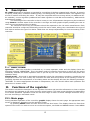
User’s manual ST-630H ST-630H 2 User’s manual Declaration of Conformity No. 71/2012 Hereby, we declare under sole responsibility that the ST-402 230V 50Hz thermoregulator manufactured by TECH, headquartered in Wieprz 1047A, 34122 Wieprz, is compliant with the Regulation by the Ministry of Economy. (Journal of Laws Dz.U. 155 Item 1089) of July 21, 2007 implementing provisions of the Low Voltage Directive (LVD) 2006/95/EC of January 16, 2007. The ST-402 controller has been tested for electromagnetic compatibility (EMC) with optimal loads applied. For compliance assessment, harmonized standards were used: PN-EN 60730-2-9:2011, PN-EN 60730-1:2012. 3 ST-630H I. Description ST–630H temperature regulator is intended for controlling CH boilers eqippped with a feeder. It controls CH pump, DHW pump, underfloor heating pump, circulating pump, fan and fuel feeder. The regulator has a built-in module controlling the valve. . It may also cooperate with two mixing valves (via additional ST61 modules), a room regulator (traditional two-state regulator or with RS communication), GSM module and Ethernet module. The advantage of the controller is that it is easy to use. All parameter changes may be introduced using buttons. Another asset of the controller is its large and clear graphic display enabling the user to check the current status of the CH boiler. All comments concerning the software should be reported to the CH boiler manufacturer. Each controller should be configured individually to suit the user's needs, taking into consideration the type of fuel used as well as the type of CH boiler. TECH does not accept responsibility for incorrect setting of the controller. I.1. Basic terms: Operation – after the controller is switched on, it enters operation mode and the display shows the following message 'OPERATION'. This is the basic mode of controller functioning in which the fan works constantly whereas the feeder operation time is pre-set by the user (the user defines both pause and operation time). Sustain mode – this mode is activated automatically when the temperature equals or exceeds the set temperature value. In such a case, the controller will slow down the process of fuel feeding in order to gradually decrease the temperature of circulating water and the display will show the following message: 'SUSTAIN'. To ensure appropriate decrease in temperature, the user should define both operation and pause time in sustain mode. II. Functions of the regulator This section includes the description of the regulator functions and provides information on how to adjust the settings and navigate in the menu structure using buttons. The main screen displays the parameters of CH boiler operation. Operation mode as well as a range of other CH boiler settings should be set by the user according to individual needs. II.1. Main page During standard operation of the controller, graphic display shows the main page. An appropriate main screen is displayed, depending on the operation mode. By pressing MENU button the user enters the first level menu. The display shows the first three options of the menu. In order to move on to the next option, use PLUS and MINUS buttons. Press MENU 4 User’s manual to select an option. Follow a similar procedure when adjusting parameters. In order for the changes to be saved, use MENU button to select CONFIRM. In order not to introduce any changes, use MENU button to select CANCEL. In order to exit, select EXIT option in the menu or press EXIT button. II.2. Screen view The user can select one of three main screens of the temperature controller operation using that function. They include: central heating screen (displays current boiler operation mode) valve (displays working parameters of the valve) valve 1 (displays working parameters of the first valve). valve 2 (displays working parameters of the second valve). NOTE The valve parameter views are available only if the valves have been properly preinstalled and configured by a technician. II.3.Preset temperature of the central heating system The option is used to set the boiler temperature. The user can change the boiler temperature within the range of 45 OC to 80OC. The preset central heating system temperature can also be changed directly in the main screen of the controller by turning the pulser knob. Additionally, the preset central heating system temperature can be adjusted using the room temperature reduction function (see Item II.15) and the weekly control function (see Item II.6). The preset temperature is a sum of all those values but it may not exceed the range of 45OC to 80OC. II.4. Preset temperature of hot domestic water The option is used to set the temperature of hot domestic water. The temperature is adjustable within the range between 40°C and 75°C., II.5. Manual mode For the user's convenience, the regulator has been equipped with the Manual mode module. In this function, each device (feeder, fan, CH pump, DHW pump, circulating pump, underfloor heating pump and valves) may be activated and deactivated independently of the others. 5 ST-630H By pressing MENU button, the user activates the motor of a given device. The device remains active until the user presses MENU button again. Additionally, blow force option is available, which enables the user to adjust the fan speed in manual mode. II.6. Weekly control The function is used to programme daily changes in the boiler temperature. The preset temperature deviations are within the range of +/-10 degrees of Celsius. Step 1: The user needs to set current time and date first (Installer menu > Clock). Step 2: The user sets temperature values for individual days of the week (Set mode 1): Monday– Sunday Select specific hours and required deviations from the preset temperature (how many degrees the temperature should rise or drop) for each day of the week. Additionally, the preset values can be copied to facilitate the operation. Example Monday preset: 3 00 , temp. -10°C (temperature change– 10°C) preset: 4 00 , temp. -10°C (temperature change – 10°C) preset: 5 00 , temp. -10°C (temperature change – 10°C) In such a case, if the temperature preset on the boiler is 60ºC, it will drop 10ºC to 50ºC between 3 a.m. and 6 a.m. on Monday. As an alternative to the temperatures being preset separately for individual days, the temperatures can also be set collectively, in the second mode, for the working days (from Monday to Friday) and the weekend (Saturday and Sunday) separately - Set mode 2. Monday - Friday; Saturday - Sunday Similarly to the previous mode it is necessary to select specific times and required deviations from the temperature preset for the working days (Monday - Friday) and the weekend (Saturday, Sunday) Example Monday - Friday preset: 3 00 , temp. -10°C (temperature change – 10°C) preset: 4 00 , temp. -10°C (temperature change – 10°C) preset: 5 00 , temp. -10°C (temperature change – 10°C) Saturday - Sunday preset: 16 00 , temp. 5°C (temperature change +5°C) preset: 17 00 , temp. 5°C (temperature change +5°C) preset: 18 00 , temp. 5°C (temperature change +5°C) In this case, if the preset boiler temperature is 60ºC, the temperature will drop 10ºC to 50ºC between 3 a.m. and 6 a.m. on each day from Monday to Friday. However, the temperature will rise 5ºC to 65ºC during weekend (Saturday, Sunday) between 4 p.m. and 7 p.m. Step 3. The user enables one of two preset modes (Mode1, Mode2) or disables the weekly control option. Once the mode is enabled the value of the deviation currently set is displayed on the main page of the controller next to the preset central heating system temperature. This, additionally, indicates that the 6 User’s manual weekly control is active. Data deletion function is a simple method to remove all previously saved weekly programme settings to enter new settings. II.7. Feeder pause Pause time is used to define the time of feeder pause. Pause length should be adjusted to the type of fuel used in the CH boiler. Incorrect operation and pause time may result in inefficient operation of CH boiler, i.e. unburnt coal or failure to reach the pre-set temperature of the CH boiler. Appropriate pause and operation time ensures efficient operation of the CH boiler. II.8. Temperature alarm Activation of this function may occur only in operation mode (i.e. when the CH boiler temperature is lower than the set temperature). If the CH boiler temperature does not increase during the period of time defined by the user (setting range: 0-12 hours), an alarm is activated: feeder and fan are switched off (the pump is switched on/off independently) and a sound signal is activated. The display shows the following message: 'CH temperature not rising'. The alarm may be cancelled by pressing MENU button. II.9. Blow force This function is used to control the fan speed. The setting range is 10-100% ( the values may be regarded as fan gears). The higher the gear is, the faster the fan works. 10% is the minimum fan speed whereas 100% is the maximum fan speed. Initially the fan always operates at a full, which enables successful activation even if the motor is dusty. II.10. Pump operation modes This function allows you to select one of the following four boiler operation modes. II.10.a) House heating When you select this option the controller switches over to a mode where heating is provided only to heat the central heating circuit. The central heating pump begins to run above the pump activation temperature (factory set at 38OC - see Section III.g). The pump will turn off below this temperature (minus a hysteresis of 2°C). 7 ST-630H II.10.b) Boiler tank priority In this mode, the boiler tank (hot water) pump will be switched on first to run until the set-point temperature is reached (see Section II.e), after which the pump will be turned off and the CH circulating pump will be enabled. The central heating pump will run all the time until the boiler tank temperature drops below its set-point by the hot water hysteresis value. At that moment the CH pump will turn off and the HW pump will turn on (both pumps operating alternately). In this mode the fan and the feeder are run only up to 62 OC as measured at the boiler (instantaneous set-point) so as to prevent overheating of the boiler. NOTE: The boiler must be fitted with check valves on the central heating and hot water pump circuits. The valve mounted on the hot water pump is to prevent drawing hot water from the boiler tank. II.10.c) Pumps in parallel In this mode both pumps begin to run together (in parallel) above the pump activation temperature.. II.10.d) II.11. Summer mode Once this function is activated the central heating pump will be off and the DHW pump will turn on above the preset activation temperature (see Section III.h) and will work continuously until the temperature drops below the activation temperature by the hot water hysteresis value or until the following conditions are met: (boiler temperature) + 2°C ≤ (boiler tank temperature) In summer mode you only enter the set-point temperature of the boiler, which is also understood to mean the set-point temperature of the boiler tank Sustain pause Sustain pause Sustain pause function is used to define the length of fuel feeding pause is sustain mode. Incorrect setting of both operation and pause time may result in further temperature increase, unintended damping of the CH boiler or may lead to fuel ignition in the fuel tank. II.12. Fan in sustain mode This option allows the user to set appropriate operation and pause time for fan operation in sustain mode (so called „blow-by”) 8 User’s manual II.13. Room temperature reduction When the room temperature regulator signalises that the set room temperature has been reached, the set CH boiler temperature (setting in the fitter's menu; see: III.16) drops by the value saved in this parameter. However, the temperature will not drop below the minimum set CH temperature. Example: Set temperature of the CH boiler: 55ºC Room temperature reduction: 15ºC Minimum set temperature of the CH boiler: 45ºC (default setting) After the set temperature of the room has been reached (signalised by the room regulator), the set temperature of the CH boiler will drop to 45ºC. The actual temperature reduction will equal 10ºC even though the pre-set value of room temperature reduction is 15ºC. The following message will appear on the main screen next to the set CH boiler temperature :„!-10º”. II.14. Factory settings The regulator is pre-configured for operation. However, the settings should be customized to the user's needs. Return to factory settings is possible at any time. When the factory settings option is activated, all customized settings of the controller (saved in user's menu) are lost and replaced with the manufacturer's settings. Then, the CH boiler parameters may be customized anew. NOTE: Restoration of factory settings does not cause deletion of changes introduced in service settings. II.15. Software version This function enables the user to check which software version is used in the controller. III. Installation menu The functions of the installation menu should be set by the person installing the boiler or service personnel of the manufacturer III.1. Valve I NOTE: Control with an additional valve (1 or 2) is only possible after you purchase and connect the controller to an additional control module (ST-61), which is not provided as standard equipment with the controller. In order to control two valves you need to connect two ST-61 modules. III.1.a) Registration To register an additional valve enter the serial number of the control module of the ST-61 mixing valve servo (look for the five-digit number on the cover of this module). Without this number the valve cannot be activated. 9 ST-630H III.1.b) Valve State This feature allows you to temporarily make the valve inactive. III.1.c) Set-point valve temperature This setting is used to set the circuit temperature to be maintained by the mixing valve. III.1.d) Temperature control This parameter determines the sampling (control) frequency of the water temperature downstream of the valve for the central heating or hot water system. If the sensor indicates a change in temperature (deviation from set-point), then the solenoid will open or close partially by a preset step to restore the set-point temperature. III.1.e) Opening time You can use this function to set the time for the full opening of the valve, that is to say, how long it takes to open the valve to 100%. This time should be selected according to your valve actuator (shown on the nameplate). III.1.f) Single step You can use this function to set a percentage value for a single step in the operation of valve opening, that is to say the maximum percentage value of opening or closing that the valve can move in a single step (maximum movement of the valve in one measurement cycle). III.1.g) Minimum opening Use this function to set the minimum value for valve opening. Below this value, the valve will not close shut. III.1.h) Type of valve You can use this option to select the type of valve: central heating or floor type. 10 User’s manual III.1.i) Weather program (weekly valve program) In order to enable the weather function an outdoor sensor should be installed in a place not exposed directly to sunlight or weather conditions. After installing and connecting the sensor the Weather program function must be enabled in the controller menu. For the valve to work properly enter set-point temperatures (downstream of the valve) for the following four intermediate outside temperatures: TEMP. FOR -20 TEMP. FOR -10 TEMP. FOR 0 TEMP. FOR 10 Heating curve - curve which is used to determine the set-point temperature of the controller based on the outside temperature. In our controller this curve is established based on four temperature set-points selected for their respective outside temperatures. Set-point temperatures must be provided for the following outside temperatures: -20ºC, -10ºC, 0ºC and 10ºC. The more points there are available for constructing the curve, the greater is its accuracy, which allows you to determine its shape in a flexible way. In our case, four points seem to be a very good compromise between accuracy and ease of setting its shape. Where in our controller: XA = -20ºC, XC = 0ºC, XB = -10ºC, XD = 10ºC, YA, YB, YC, YD – set-point valve temperatures for their corresponding outside temperatures: XA, XB, XC, XD After weather control is enabled the valve set-point parameter is calculated based on the heating curve. By changing this parameter you can decrease or increase all the weather control settings. III.1.j) Return protection This feature allows you to enable protection for the boiler from excessively cold water returning from the main circuit, which could cause the boiler to suffer from low-temperature corrosion. The return protection function works to ensure that when the temperature is too low the valve will close partially until the short circuit of the boiler reaches the desired temperature. This feature also protects the boiler from a dangerously high return temperature to prevent water from boiling. When this function is enabled you need to set the minimum and maximum return temperatures. III.1.k) Additional sensors When two mixing valves are used and you select this function you will be able to select the sensors from which temperature data are to be retrieved for a valve (for return and outside temperature sensors). Temperatures can be retrieved from the sensors of the valve being set (Own) or as per the controller sensors (Main controller). III.1.l) Room temperature regulator function This function is used to define how the room regulator settings should influence a given valve status. Room regulator – this option is used to select the type of room regulator, cooperating with the valve. The following options are available:: Switched off – the room regulator status does not influence the valve settings Standard regulator – a two-state regulator. In the case of external valves (valves 1 and 2), this settings refers to the regulator which is connected directly to the valve controlling module (ST-61). In 11 ST-630H the case of an internal valve, this setting refers to the room regulator connected directly to ST-630H controller. TECH regulator – regulator with RS communication Proportional controll– option available only in the case of TECH regulators with RS communication. It works correctly after Change of the set valve temperature and Room temperature difference options are configured. Room temperature reduction - When the room regulator signalises that the set temperature of the room has been reached, the set valve temperature will be reduced by the value saved in this parameter. (Function unavailable when Proportional control function is selected) Change of the set valve temperature – This setting determines by how many degrees the valve temperature is to increase or decrease with a single unit change in room temperature (see: Room temperature difference) This function is active only with TECH room temperature regulator and it is closely related to the Room temperature difference parameter. Room temperature difference - This setting is used to define the single unit change in the current room temperature (with the accuracy of 0.1°C) at which a predefined change in the set temperature of the valve will be introduced (function available only with TECH room temperature regulator). III.1.m) External sensor adjustment This function enables calibration of external sensor temperature. III.1.n) Factory settings This function is used to restore a given valve to its factory settings, predefined by the manufacturer. Restoration of factory settings does cause change of valve type selected (CH valve or underfloor heating valve). III.1.o) Valve removal (function available only for valves 1 and 2) This function is used to remove the valve from the controller memory. Valve removal is used e.g. at disassembling the valve or module replacement (re-registration of a new module is necessary). III.1.p) Software version (function available only for valves 1 and 2) This function enables the user to check which software version is used in the valve control module. III.2. Temperature of pump activation This function is used to set the temperature of activation for CH pump and DHW pump (temperature measured at the CH boiler). When the temperature is below the set value, both pumps are inactive. When the temperature is above the set value, both pumps are activated and operate according to the selected operation mode (see: pump operation modes) III.3. CH boiler hysteresis This option can be used to set the hysteresis of the set CH temperature. It is the difference between the temperature of entering the sustain mode and the temperature of returning to the operation mode (e.g. when the set temperature value is 60ºC and the hysteresis is 3ºC, entering the sustain mode will take place at 60ºC, whereas returning to the operation mode will take place at 57ºC. 12 User’s manual III.4. CH boiler hysteresis This option can be used to set the hysteresis of the set CH temperature. It is the difference between the temperature of entering the sustain mode and the temperature of returning to the operation mode (e.g. when the set temperature value is 60ºC and the hysteresis is 3ºC, entering the sustain mode will take place at 60ºC, whereas returning to the operation mode will take place at 57ºC. III.5. TECH regulator ST-630H may be connected to a room temperature regulator. This function enables the user to configure the regulator by selecting the type of room temperature regulator connected to ST-630 controller. Here, the user may also check the software version used in the room temperature regulator. Connecting TECH regulator enables the user to monitor and change the set temperature of CH and DHW, as well as the set temperature of the mixing valve. Moreover, the regulator displays all alarms of the CH boiler controller. In the case of controlling mixing valve, the user may preview the current external temperature displayed in the main screen view with the valve parameters. After selecting TECH regulator option, letter 'P' will be displayed in the upper part of the main screen of the controller. Flashing 'P' indicates that the room temperature is too low. After the set temperature of the room is reached, 'P' is displayed steadily. ATTENTION: No external voltage may be connected to the room regulator output. Room temperature regulator function enables the user to program the room regulator operation: switched off – room regulator status does not influence other settings Kocioł – CH boiler– after the room regulator signalises that the set temperature has been reached, the set CH boiler temperature will drop (detailed settings – see: II.15) CH pump - after the room regulator signalises that the set temperature has been reached, the CH pump will be switched off (detailed settings – see: II.15) III.6. GSM module NOTE: Controlling of this type is possible after purchasing and connecting, to the controller, the additional control module ST-65 which is not attached to the regulator as a standard feature. The GSM module is an optional device cooperating with the boiler controller, enabling remote control of the boiler operation with the use of a mobile phone. The User is notified with a text message on each alert of the boiler controller, and by sending an appropriate text message at any time, he or she receives a return message with the information on the current temperature of all sensors. After entering an authentication code it is also possible to remotely change the set temperatures. The GSM module can also operate independently from the boiler controller. It has two inputs with temperature sensors, single contact input for use in any configuration (detecting short circuit/opening of contacts) and one controlled output (e.g. possibility to connect additional contactor to control any electrical circuit). When any temperature sensor reaches the preset deactivation temperature, maximum or minimum, the module will automatically send a text message with such information. It is similar in the case of a short-circuit or opening of contact input, which may be used e.g. for simple protection of property. III.7. Internet module NOTE: Controlling of this type is possible after purchasing and connecting, to the controller, the additional control module ST-500 which is not attached to the regulator as a standard feature. The Internet module is a device enabling remote control of the boiler over the Internet or local network . On the home computer screen the user controls the condition of all boiler system devices and the operation of each device is presented in the animated form. Apart from the possibility to view the temperature of every sensor, the user has the possibility of introducing changes of the set temperatures for both the pumps and the mixing valves. 13 ST-630H After activating the Internet module and selecting the DHCP option, the controller will automatically download such parameters from the local network as: IP address, IP Mask, Gateway address and DNS Address. In the case of any problems with downloading network parameters of the existing network, there is a possibility of setting these parameters manually. The method of obtaining local network parameters has been described in the instructions for the Internet module. The function Reset module password may be used when the User, on the login page, has changed the factory user's password to his or her password. When a new password is lost, it is possible to return to the factory password after resetting the module password . III.8. Feeder in auto mode This function is used to activate or deactivate automatic feeder operation. Feeder may be switched off in order to feed fuel manually or damp the CH boiler. III.9. Fan in auto mode This function is used to activate or deactivate automatic fan operation. Fan may be switched off in order to manually adjust the chimney draft. III.10. Underfloor heating pump This function is used to control the underfloor heating system. The user defines the set temperature value for the underfloor heating within the range of 30oC – 55oC. After switching on the undefloor heating pump, the user defines the minimum (threshold) temperature of pump activation (measured at the CH boiler) as well as the maximum (set) temperature of underfloor heating (measured at the pump sensor) When the temperature is below the minimum, the pump is inactive. When the temperature exceeds this value, the pump is activated and operates until the set maximum temperature value is reached. After the set temperature has been reached, the pump is switched off. It will be activated again when the temperature drops 2oC below the set value. III.11. Circulating pump This function is used to control the pump which mixes hot water between the CH boiler and DHW receivers. After activating this function, the user sets the 24-hour minutes). In order to make setting the 24-hour cycle easier, the user may copy a selected time interval into the next one. After the operation plan is defined, the user sets the pump operation time and the pump pause time while the previously selected time interval is active. The user may easily delete the previously saved settings in order to introduce new intervals. 14 User’s manual III.12. Clock You can use the clock settings to enter the current time and day of the week. III.13. Set the date The function is used to set current date (day and month). III.14. Language selection Using this function, the user selects the language in which the controller will be operated. IV. Service menu In order to enter the service menu of the ST630H controller, enter a 4-digit code. The code is available in TECH company. V. Protections In order to ensure safe and failure-free operation, the regulator has been equipped with a range of safeguards. In case of alarm, a sound signal is activated and the display shows an appropriate message. V.1. Temperature alarm This protection may be activated only in operation mode (i.e. when the CH boiler temperature is lower than the set temperature). If the CH boiler temperature does not increase during the period of time defined by the user, an alarm is activated: feeder and fan are switched off and a sound signal is activated. The display shows the following message: 'CH temperature not rising'. The alarm may be cancelled by pressing MENU BUTTON. The controller will return to the previously selected mode of operation. V.2. Thermal protection The controller is equipped with a bimetallic mini-sensor (placed next to CH boiler temperature sensor or on the supply pipe, as close to the CH boiler as possible), which automatically disconnects the fan and feeder from the power supply when the alarm temperature of about 85-90°C is exceeded. It prevents the water in the installation from boiling in the case of CH boiler overheating or controller damage. After this protection has been activated and the temperature has dropped to a safe level, the sensor will automatically unlock itself. In the case when this sensor is damaged or overheated, both the fan and feeder will be disconnected. NOTE: In the case when the thermal overload relay is damaged, the fan does not operate either in manual mode or in automatic mode V.3. Automatic sensor check If the temperature sensor of CH, DHW, feeder or fuel tank is damaged, an alarm sound is activated and the display message informs about the failure; e.g.: 'CH sensor damaged'. Both feeder and fan remain 15 ST-630H active. The pump operates regardless of the current temperature. The alarm will be active until a new sensor is installed. If the CH sensor or feeder sensor is damaged, the alarm will be active until a new sensor is installed. In the case of DHW sensor damage, the alarm may be switched off by pressing MENU button – the controller will restore operation with one pump (CH). A new sensor should be installed so that all modes of CH boiler operation were available. V.4. Protection against boiling of water in the CH boiler This protection concerns only water boiler priority mode, in the case when the water tank is insufficiently heated. When the set temperature of water boiler is 55 OC whereas the actual CH boiler temperature reaches 62OC (so called priority temperature), the controller disables the fan and feeder. If the CH boiler temperature still increases reaching 80 OC, the CH pump will be switched on. In the case of further temperature increase, an alarm will be activated at the temperature of 85OC. Such a situation usually occurs when the water boiler or pump is damaged or when the sensor is incorrectly mounted. When the temperature drops, at the threshold of 60OC the controller will enable the fan and feeder and it will remain in operation mode until the temperature of 62OC is reached. V.5. Temperature protection The regulator has an additional protection against hazardous temperature growth. If the alarm temperature of 80OC is exceeded, the fan is disabled and the pumps are switched on simultaneously in order to distribute hot water throughout the house installation. When the temperature of 85 OC is exceeded, an alarm is activated and the display shows the following alarm message: Temperature too high. In order for the controller to return to previous operation mode, its temperature must decrease below the alarm value and the user must press MENU button to delete the alarm. V.6. Feeder protection There is an additional sensor measuring temperature on the feeder. In the event of a significant temperature increase (above 85OC), an alarm is activated: the feeder is enabled every 20 minutes, which moves the fuel into the combustion chamber. Feeder sensor prevents the fuel in the tank from igniting. V.7. Hall effect sensor of the feeder ST-630H controller is equipped with an additional feeder protection – Hall effect sensor, which monitors fuel feeding. If the feeder fails to make a full turn, the following alarm message will appear: Clean the feeder. When the feeder makes a full turn, 'k' will appear on the screen indicating that the reed sensor detects a magnet. V.8. Fuse The regulator has two WT 6.3A tube fuse-links protecting the network. Caution: Higher amperage fuse should not be used as it may damage the controller. VI. Maintenance Before and during the heating season, ST-630H controller should be checked for condition of its cables. You should also check if the controller is properly mounted and clean it if dusty or dirty. It is advisable to measure earthing parameters for the motors (CH pump, DHW pump, fan, feeder, underfloor heating pump and circulating pump). 16 User’s manual No. 1 2 3 4 5 6 7 8 9 10 11 VII. Specification Power supply Maximum power consumption Ambient temperature Output load of CH pump, DHW pump, underfloor heating pump, circulating pump, valve Fan output load Feeder output load Range of temperature measurement Accuracy of measurement Range of temperature settings Thermal resistance of the sensor Fuse Jedn. V W ˚C A A A ˚C ˚C ˚C ˚C A 230V/50Hz +/-10% 11 5÷50 0,5 0,6 2 0÷90 1 45÷80 -25÷90 6,3 Installation ATTENTION: The device should be installed by a qualified person. During installation the device mustn't be powered! (make sure the plug is disconnected from the power supply!) ATTENTION: Incorrect connection of the wires may damage the regulator! ATTENTION: ST-630H controller must be embedded in the CH boiler housing in order to ensure sufficient protection of the cables and the mounting strip. 17 ST-630H VII.1. Controller wiring diagram Particular attention should be paid when connecting the controller cables to the correct connection of the earthing wires. 18 User’s manual Table of contents I. Description ........................................................................................................................ 4 I.1. II. Basic terms: ................................................................................................................................................................................................................ 4 Functions of the regulator .................................................................................................... 4 II.1. II.2. II.3. II.4. II.5. II.6. II.7. II.8. II.9. II.10. II.11. II.12. II.13. II.14. II.15. III. Installation menu ............................................................................................................. 9 III.1. III.2. III.3. III.4. III.5. III.6. III.7. III.8. III.9. III.10. III.11. III.12. III.13. III.14. IV. V. Main page .................................................................................................................................................................................................................. 4 Screen view ................................................................................................................................................................................................................ 5 Preset temperature of the central heating system ..................................................................................................................................................... 5 Preset temperature of hot domestic water ................................................................................................................................................................ 5 Manual mode ............................................................................................................................................................................................................. 5 Weekly control ........................................................................................................................................................................................................... 6 Feeder pause .............................................................................................................................................................................................................. 7 Temperature alarm ..................................................................................................................................................................................................... 7 Blow force .................................................................................................................................................................................................................. 7 Pump operation modes .............................................................................................................................................................................................. 7 Sustain pause ............................................................................................................................................................................................................. 8 Fan in sustain mode.................................................................................................................................................................................................... 8 Room temperature reduction ..................................................................................................................................................................................... 9 Factory settings .......................................................................................................................................................................................................... 9 Software version......................................................................................................................................................................................................... 9 Valve I ......................................................................................................................................................................................................................... 9 Temperature of pump activation .............................................................................................................................................................................. 12 CH boiler hysteresis .................................................................................................................................................................................................. 12 CH boiler hysteresis .................................................................................................................................................................................................. 13 TECH regulator ......................................................................................................................................................................................................... 13 GSM module............................................................................................................................................................................................................. 13 Internet module ....................................................................................................................................................................................................... 13 Feeder in auto mode ................................................................................................................................................................................................ 14 Fan in auto mode..................................................................................................................................................................................................... 14 Underfloor heating pump......................................................................................................................................................................................... 14 Circulating pump ...................................................................................................................................................................................................... 14 Clock ......................................................................................................................................................................................................................... 15 Set the date .............................................................................................................................................................................................................. 15 Language selection ................................................................................................................................................................................................... 15 Service menu ................................................................................................................ 15 Protections....................................................................................................................... 15 V.1. V.2. V.3. V.4. V.5. V.6. V.7. V.8. VI. VII. VII.1. Temperature alarm ................................................................................................................................................................................................... 15 Thermal protection .................................................................................................................................................................................................. 15 Automatic sensor check ........................................................................................................................................................................................... 15 Protection against boiling of water in the CH boiler ................................................................................................................................................. 16 Temperature protection ........................................................................................................................................................................................... 16 Feeder protection ..................................................................................................................................................................................................... 16 Hall effect sensor of the feeder ................................................................................................................................................................................ 16 Fuse .......................................................................................................................................................................................................................... 16 Maintenance .................................................................................................................. 16 Installation .................................................................................................................... 17 Controller wiring diagram......................................................................................................................................................................................... 18 Care for the natural environment is our priority. Being aware of the fact that we manufacture electronic devices obligates us to dispose of used elements and electronic equipment in a manner which is safe for nature. As a result, the company has received a registry number assigned by the Main Inspector of Environmental Protection. The symbol of a crossed out rubbish bin on a product means that the product must not be thrown out to ordinary waste bins. By segregating waste intended for recycling, we help protect the natural environment. It is the user's responsibility to transfer waste electrical and electronic equipment to the selected collection point for recycling of waste generated from electronic 19 ST-630H 20


![Manuel d`utilisation Régulation TECH ST3[...]](http://vs1.manualzilla.com/store/data/006377962_1-761c4fa99f631e7c2b8551b5818edead-150x150.png)