1
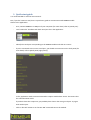
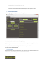
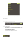
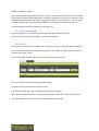
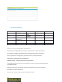
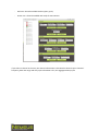
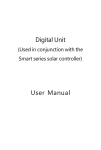
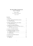
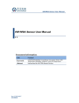
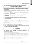
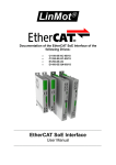
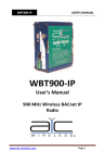
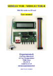
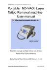
Nemeus Client
App
User Manual
v0.5
Table of contents
Disclaimer............................................................................................................................................... 3
Document history................................................................................................................................... 4
References.............................................................................................................................................. 4
Revisions................................................................................................................................................. 4
1.Quick start guide.................................................................................................................................. 5
2.General description............................................................................................................................. 5
2.1Serial port ..................................................................................................................................... 6
2.1.1Communication with Nemeus module....................................................................................... 6
2.1.2 Shell panel (right panel)............................................................................................................. 6
2.2RF tab............................................................................................................................................. 7
2.2.1Top panel.................................................................................................................................... 7
2.2.2RF command panel (left panel)................................................................................................... 7
2.3MAC tab......................................................................................................................................... 8
2.3.1Top panel.................................................................................................................................... 8
2.3.2MAC command panel (left panel)............................................................................................... 8
2.4LRC tab .......................................................................................................................................... 9
3.Menu description............................................................................................................................ 9
4.Basic RF Demo .................................................................................................................................. 10
5.Advanced functions........................................................................................................................... 11
5.1Load binary.................................................................................................................................. 11
5.2Rx/Tx parameters......................................................................................................................... 11
5.3Mac parameters........................................................................................................................... 11
5.4AT command................................................................................................................................ 12
6.Troubleshooting................................................................................................................................. 12
2
Disclaimer
1.
This document is provided for reference purposes only so that Nemeus customers may select the
appropriate products for their use. Nemeus neither makes warranties or representation with respect to
the accuracy or completeness of the information contained in this document, nor grants any license to any
intellectual property rights or any other rights of Nemeus or any third party with respect to the information
in this document.
2.
You should not use the products or the technology described in this document for the purpose of military
applications such as the development of weapons of mass destruction or for the purpose of any other
military use. When exporting the products or technology described herein, you should follow the
applicable export control laws and regulations, and procedures required by such laws and regulations.
3.
All information included in this document such as product data, diagrams, charts, programs, algorithms,
and application circuit examples, is current as of the date this document is issued. Such information,
however, is subject to change without any prior notice. Before purchasing or using any Nemeus products
listed in this document, please confirm the latest product information with Nemeus company.
4.
Nemeus has used reasonable care in compiling the information included in this document, but Nemeus
assumes no liability whatsoever for any damages incurred as a result of errors or omissions in the
information included in this document.
5.
When using or otherwise relying on the information in this document, you should evaluate the information
in light of the total system before deciding about the applicability of such information to the intended
application. Nemeus makes no representations, warranties or guaranties regarding the suitability of its
products for any particular application and specifically disclaims any liability arising out of the application
and use of the information in this document or Nemeus products.
6.
Nemeus products are not designed, manufactured or tested for applications or otherwise in systems the
failure or malfunction of which may cause a direct threat to human life or create a risk of human injury or
which require especially high quality and reliability such as safety systems, or equipment or systems for
transportation and traffic, healthcare, combustion control, aerospace and aeronautics, nuclear power, or
undersea communication transmission. Use of Nemeus products for such application is under customer
responsibility.
7.
You should use the products described herein within the range specified by Nemeus, especially with
respect to the maximum rating, operating supply voltage range, movement power voltage range, heat
radiation characteristics, installation and other product characteristics. Nemeus shall have no liability for
malfunctions or damages arising out of the use of Nemeus products beyond such specified ranges.
8.
In case Nemeus products listed in this document are detached from the products to which the Nemeus
products are attached or affixed, the risk of accident such as swallowing by infants and small children is
very high. You should implement safety measures so that Nemeus products may not be easily detached
from your products. Nemeus shall have no liability for damages arising out of such detachment.
9.
This document may not be reproduced or duplicated, in any form, in whole or in part, without prior written
approval from Nemeus.
3
10. Please contact Nemeus company ( [email protected]) if you have any questions regarding the
information contained in this document.
4
Document history
Version
V0.1
V0.2
V0.3
V0.4
V0.5
V0.6
Date
27/06/2014
22/07/2014
24/07/2014
03/11/2014
14/11/2014
27/05/15
Author
Alan Kreutz
Alan Kreutz
Alan Kreutz
Alan Kreutz
Alan Kreutz
Alan Kreutz
Comments
Initial
Description of MAC tab
Description of LRC tab
MAC V3 update
Update upload procedure
Update document with latest application
modification
V0.7
30/06/15
Alan Kreutz
Update with new menu
Table 1 : Document versions
References
[1] Nemeus / AT command API guide MM001-S1-140624-AT_command_v0.2
[2] Semtech / IBM / Actility –LoRa MAC Class A Specification R3.1
Revisions
This document is dedicated to Nemeus Java client application description.
5
1. Quick start guide
It is recommended to read the entire manual.
But, if you don’t want to read, here is a quick start guide to communicate with MM00X module
thanks to the application.
-
First, connect MM00X to a USB port of your computer (for more detail, refer to §Serial port).
-
Tick “Local Echo” checkbox and check serial port list in the application:
-
Identify the serial port corresponding to the MM00X module and click on Connect
-
If you’re connected to the correct serial port, you should see some text on the shell panel (for
more detail, refer to §Shell panel (right panel)):
In fact, application sends some AT command to request module basic status. This means that
the communication works.
If you don’t have this output text, you probably have chosen the wrong serial port. Try again
with another port.
-
6
Click on “RF ON” button to see “AT+RF= ON” command sent to the module.
The MM00X should answer with +RF: ON or OFF
To quickly test communication between 2 modules, please refer to §Basic RF Demo.
2. General description
The following image shows the general aspect of Java application:
This chapter describes the different part of the application.
Application allows to communicate with MM00X module by serial port. This is a graphical interface
for the serial port communication.
On top of the window (below menu bar), we have three tabs RF, MAC and LRC.
Let’s have a look to the different parts.
2.1 Serial port
We first introduce the serial port communication. Java application is just a graphical interface to the
serial port. First, you must identify and connect to the MM00X module.
7
2.1.1 Communication with Nemeus module
Available on top of RF & MAC tabs, the Serial Port part lists the connected serial ports.
A Connect/Disconnect button allows to connect to a serial port with the following configuration:
-
Baud rate: 38400
-
Data: 8 bits
-
Parity: None
-
Stop: 1 bit
-
Flow control: None
A “Local Echo” checkbox is present to enable/disable the shell echo for AT command.
You must identify the MM00X serial port on your computer. Connection is possible to any serial port
without issue. To check that you’re connected to MM00X module, Java application sends a set of AT
command to read module status at connection.
2.1.2 Shell panel (right panel)
The shell panel is common to RF & MAC tabs. This text area displays the input and output text of
module.
8
You’ll see the AT command request and response and some debug information.
A command line besides the “Send Command” button allows to send AT command (if user knows
about AT command).
CLS clears the window content.
2.1.3 Top panel
The top part of the application is composed of 3 regions.
From left to right, you can find:
9
-
Monitoring Rx values (RSSI, SNR and Rx Success) updated depending on AT response
received.
-
Serial port management (refer to § Serial port )
-
Load binary button (refer to load procedure § Load binary)
2.2 Command panel
This is the left panel of application. There are two tabs. One for RF and one for MAC.
2.2.1 RF command tab
The RF command tab is composed of several components.
These commands allow to control the RF modem by sending pre-registered AT command.
The possible actions are:
-
“RF ON/OFF” button depending on module RF state. This button switches RF module from
ON to OFF or OFF to ON.
-
Tx Start Demo (refer to demo part for more detail § Basic RF Demo)
-
-
10
o
“TX ON” to start TX demo.
o
“TX OFF” to stop TX demo
o
Text field to check the last frame number sent
Rx Start Demo
o
“RX ON” to start continuous RX mode
o
“RX OFF” to stop continuous RX mode
o
Text field to check the last frame received
GPS Demo (only available with corresponding sensor)
2.2.2 MAC command tab
For MAC test in front of a gateway, you can use this tab to test MAC functionalities.
2.2.2.1
MAC start/stop
The panel offers a button to switch MAC on/off.
According to device capabilities, you could select the MAC class (A or C). If this combo box is not
enabled, it seems your device is not Class C compatible.
You could select the activation procedure if the device allow it. The second combo box offers 2
choices ABP or OTAA for activation. ABP is for Activation By Personalization. The device Address is
stored in device file system. OTTA for Over The Air Activation. The device Address is provided by the
network.
2.2.2.2
MAC LCR
Then, you can send a Link Check Request and checks the result returned by the gateway.
2.2.2.3
MAC send
You can send a MAC frame with some options (ACK or UNACK frame), send Binary payload or Text
payload, set the number of repetition and the Mac port.
Check ADR and PiggyBacked status.
11
Enable or disable encryption.
You can send periodic MAC frame by setting a number of period and a period value. The “Periodic
Send” button enables periodic MAC frames sending. If the period is too short, the application will
automatically increase the timer value (according to time on air transmission etc...). If duty cycle
occurs during periodic send, some frame could be transmitted later than the base period.
A text area displays the last received frame following a Tx.
2.2.3 MAC information
The last component is a text area with some MAC information about the device.
Mac version, device UID, device address, network ID, ISM bands.
2.3 LRC tab
Please note that this tab is only useful if you’ve access to a LRC server (not provided by Nemeus).
LRC server used in MAC communication (via gateways) could allow to register frames in order to
simulate traffic (LRC->mote).
On top of the LRC tab panel, you have different fields to configure for this.
First, you can find a combo box with pre-registered LRC.
The UDP port for communication with LRC server.
The device ID destination, mac port and payload you want to register.
After clicking on Register button, you can briefly check the result in the “Server response” part.
In the panel below, you find the 100 last received MAC frames payload.
12
3. Menu description
File
Load
Config
Rx parameters…
Quit
Tx parameters…
Mac V3
parameters…
Device Perso
Control
Init module
step
Wakeup
module
Reset device
Debug
Verbose ON
Help
About
Verbose OFF
Factory Reset
LoRa Mac Cfg...
Load item: refer to Load procedure (§ Load binary).
Rx parameters: configure RX channel (refer to Rx parameters § Rx/Tx parameters).
Tx parameters: configure TX channel (refer to Tx parameters § Rx/Tx parameters).
Mac V3 parameters: configure Mac parameters (refer to § Mac parameters).
Device Perso: configure Device Personalization
LoRa Mac Config...: read and set loramac.cfg in filesystem
Init module step (Ctrl+I): Start the init procedure in case of missing information following
reset/disconnection…
Wakeup module (Ctrl+W): Wakeup sleeping module (linked to powersaving feature).
Reset device (Ctrl+R): Reset device.
Factory reset : Facoryt reset. Be careful, file system is reset.
13
Verbose ON (Ctrl+N): Activate verbose trace
Verbose OFF (Ctrl+F): Disable verbose trace
4. Basic RF Demo
You must have two MM00X modules.
1. Connect MM00X with USB cable on the same computer (or two different computers).
2. Start application twice if MM00X modules are connected to the same computer.
3. Detect the USB serial port used by MM00X in order to connect to the correct serial port.
4. Choose the serial port and click on “Connect”.
5. You should see “Connected!!!” displayed on shell panel. And if connected to the serial port of
MM001, you should see responses to AT commands. If not, you are not connected to
MM001. Try to identify the device serial port again.
6. Once connected, some buttons of the RF Command panel are enabled. Switch ON the RF if
needed by clicking on “RF ON” button. If you only see “RF OFF”, that means the MM00X has
already the Radio ON.
7. The “RX ON” & “TX ON” buttons are now available. Click on “RX ON” to configure MM00X on
continuous RX mode.
8. Repeat step 3 to 6 for the second MM00X.
9. Last step for the second MM00X, click on “TX ON” in order to send a periodic frame (every 5
seconds).
On TX module, you must see frames being sent.
On RX module, you should see reception of frames. +RFRX: …<data frame>
The frame sent contains an ID (generated randomly at application start) on 2 bytes and a counter
on 2 bytes as data payload. You can check the frame on reception thanks to this number.
14
Note that, the reference ID in Rx mode is saved when module received his first frame. Remember this
if you have problem during demo with LoRa interferences around or if you want to test 2 demos in
parallel.
5. Advanced functions
5.1 Load binary
If you have a new software to load on MM00X, you can do it with the Load function (File->Load in
menu or “Load Binary…” button).
You’ll be noticed of the flashing procedure if needed.
5.2 Rx/Tx parameters
For advanced users, Rx and Tx parameters are configurable.
Please refer to LoRa MAC specification document in order to configure correct parameters.
Rx parameters and Tx parameters configuration are available by menu Config->Rx parameters or
Config->Tx parameters.
15
16
A simple couple of button to get the actual configuration and set the wanted configuration.
5.3 Mac parameters
Mac parameters are totally configurable too.
Please refer to LoRa Mac specification v3.x to know about Mac parameters.
In menu Config->Mac V3 Parameters… a dialog box allows to access the Mac channels configuration.
There are 16 possible channels (taken from LoRa Mac specification).
In left, you find a Tree with channels node.
You must first “Read All Channels”. This allows to get the 16 channels configuration.
Icon color gives indication on channels (updated after every Mac frame sending):
17
-
Light gray icon: No channel configured
-
Dark gray icon: channel not configured in Channel Mask
-
Red icon: channel available but busy (Duty cycle)
-
Green icon : channel available and ready for transmission
If you select a channel in the tree, the channel information is described in Channels part. Channel’s
frequency, data rate range and duty cycle information. Plus, the Aggregated Duty Cycle.
18
Then, you find the different information about Mac parameters:
19
-
Data Rate (data rate to use, Tx power, Channel mask, channel mask control and repetition)
-
Time Info (Rx window 1 & 2 and symbolic time out)
-
Rx info (Rx2 channel frequency & data rate and Rx1 data rate offset)
5.4 AT command
For advanced users, you can command MM00X with AT command based on the AT command user
guide in order to have more possibilities.
Just enter your AT command in the command line above the shell.
6. Troubleshooting
If the module doesn’t react to the application stimuli:
-
Disconnect & reconnect module (via Serial Port panel)
-
Reset module
-
Check the module USB connection
For debug, application generates 1 fileslog-mm001-<date>.txt.
The console output (when run by command line) generates an xml-like file.
You can copy/paste the output in a xml file to see MAC messages traces. If you copy/paste while the
application is running, you must add the </xml> tag at the end of your file.
20