1
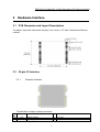
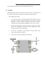
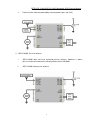
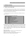
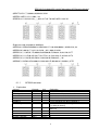
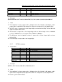
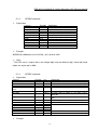
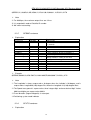
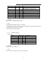
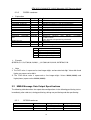
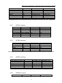
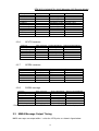
User’s Manual
SPK-GPS-Y1020A/GPS-Y1020P
Mountable GPS Receiver Module
Version 1.00
SPK-GPS-Y1020A/GPS-Y1020P Mountable GPS Receiver Module
Copyright © 2005 by S.P.K. ELECTRONICS CORP. All rights reserved.
The drawings, specifications and the data contained herein are the exclusive property of
S . P . K . ELECTRONICS CORP. issued in strict confidence and shall not, without the
prior written permission of S . P . K . ELECTRONICS CORP., be reproduced, copied or
used, in parts or as a whole, for any purpose whatsoever, except the manufacture of articles
for S.P.K. ELECTRONICS CORP.
S.P.K. makes no warranties with respect to the correctness, accuracy or wholeness of
this specification. The information in this document is subject to change without notice.
S.P.K. reserves the right to make revisions to this document and the product described
herein without obligation to notify any person or entity of any such changes.
Date: Apr. 8th, 2005
S.P.K. ELECTRONICS CO.,LTD.
10F, No. 510,SEC. 5 ,CHUNG HSIAO E.RD, TAIPEI, TAIWAN
E-MAIL:[email protected] WEB:http://www.spkecl.com
ii
SPK-GPS-Y1020A/GPS-Y1020P Mountable GPS Receiver Module
Revision History
Ver.
1.00
Date
Apr. 8th, 2005
Description
Initial Draft
iii
SPK-GPS-Y1020A/GPS-Y1020P Mountable GPS Receiver Module
Contents
1
2
INTRODUCTION.................................................................................................................................. 1
1.1
OVERVIEW.............................................................................................................................. 1
1.2
FEATURES ............................................................................................................................... 1
1.3
TECHNICAL SPECIFICATIONS.................................................................................................... 2
1.4
SERIAL COMMUNICATION INTERFACE ...................................................................................... 2
1.5
INITIALIZATION ....................................................................................................................... 2
1.6
NAVIGATION ........................................................................................................................... 3
HARDWARE INTERFACE................................................................................................................... 4
2.1
PCB DIMENSION AND LAYOUT DESCRIPTIONS ......................................................................... 4
2.2
30-PIN I/O INTERFACE ............................................................................................................. 4
2.2.1
Electrical interface................................................................................................................. 4
2.2.2
Mechanical interface.............................................................................................................. 6
2.3
3
6-PIN CONNECTOR INTERFACE ................................................................................................. 6
2.3.1
Electrical interface................................................................................................................. 6
2.3.2
Mechanical interface.............................................................................................................. 6
2.4
ANTENNA ............................................................................................................................... 7
2.5
POWER SAVING MODE ............................................................................................................. 9
SOFTWARE INTERFACE...................................................................................................................10
3.1
NMEA TRANSMITTED MESSAGES ..........................................................................................10
3.1.1
GPGGA sentence ..................................................................................................................11
3.1.2
GPGLL sentence ...................................................................................................................12
3.1.3
GPGSA sentence ...................................................................................................................13
3.1.4
GPGSV sentence ...................................................................................................................13
3.1.5
GPRMC sentence ..................................................................................................................14
3.1.6
GPVTG sentence...................................................................................................................14
3.1.7
GPZDA sentence...................................................................................................................15
3.1.8
PSGSA sentence....................................................................................................................16
3.2
NMEA MESSAGE DATA OUTPUT SPECIFICATIONS ...................................................................16
3.2.1
GPGGA sentence ..................................................................................................................16
3.2.2
GPGLL sentence ...................................................................................................................17
3.2.3
GPGSA sentence ...................................................................................................................17
3.2.4
GPGSV sentence ...................................................................................................................17
3.2.5
GPRMC sentence ..................................................................................................................17
3.2.6
GPVTG sentence...................................................................................................................18
3.2.7
GPZDA sentence...................................................................................................................18
iv
SPK-GPS-Y1020A/GPS-Y1020P Mountable GPS Receiver Module
3.2.8
3.3
4
PSGSA message ....................................................................................................................18
NMEA MESSAGE OUTPUT TIMING .........................................................................................18
OPTIONS SUMMARY .........................................................................................................................20
v
SPK-GPS-Y1020A/GPS-Y1020P Mountable GPS Receiver Module
1 Introduction
1.1
Overview
The S P K GPS-Y1020A/GPS-Y1020P mountable GPS receiver module is a single side
Global Position System Receiver. Innovative packaging technologies enable the high
integration of GPS receiver in a small module measuring just 25.4mm x 25.4 mm and allowing
the straightforward integration in particularly small end products and the opportunities in new
application fields.
The GPS-Y1020A/GPS-Y1020P shows the mini size, high performance, low power
consumption and is suitable for handheld applications. It is also the first application of such
small single side GPS unit based on the newest SONY architecture in the world.
1.2
Features
The GPS-Y1020A/GPS-Y1020P provides the features that make the host easy for
integration.
Full implementation of SONY CXD2951 architecture.
12 parallel satellite-tracking channels for fast acquisition and reacquisition
Provide superior navigation performance in urban canyon and foliage environments
Ultra small, single side and low power consumption
Support NMEA0183 v3.01 data protocol or SONY binary code
Full navigation accuracy provided by Standard Positioning Service (SPS).
Integrated powerful CPU, base band and RF hardware in an SOC (System On Chip)
design reduces the space and power consumption in state of the art.
High performance firmware drives an excellent positioning speed.
No any initialization setup is required while start to use.
Fully shielded.
Postage stamp type package.
No RF connector, RF input via pin.
Battery supply pin for real time clock and backup memory.
Power saving support.
1
SPK-GPS-Y1020A/GPS-Y1020P Mountable GPS Receiver Module
1.3
Technical Specifications
Features
Specifications
GPS receiver:
L1, C/A code, 12 channels
Tracking sensitivity:
–152dBm (average) or better
Acquisition sensitivity:
–139dBm (average) or better
TTFF (Time to First Fix):
Cold Start: 50s (average) / 60s (95% possibility)
Warm Start: 35s (average) / 40s (95% possibility)
Hot Start: 2s (minimum) / 6s (95% possibility)
Positioning accuracy:
Standard Positioning Service (SPS), WAAS (optional)
2DRMS: approx. 5m
Time accuracy:
1 s or less precision
Measurement data output:
Update time: 1 second
NMEA output protocol: V.3.01
Baud rate: 4800, 9600, 19200, 38400 bps (8-N-1)
Datum: WGS-84
Type: GGA, GSA, GSV, RMC, VTG, ZDA, GLL, SONY
Binary
Power consumption:
39mA (average)
Power supply:
3.3V
Antenna type:
GPS-Y1020A: Active antenna
GPS-Y1020P: Passive antenna
1.4
Dimension:
single side 25.4(W) x 25.4(L) x 3.6(H) mm
Operating temperature:
-40°C ~ +85°C
Storage temperature:
-55°C ~ +100°C
Serial Communication Interface
1. Serial communication channel and user selectable baud rate among 4800, 9600,
19200, and 38400 (default 4800) bps.
2. NMEA 0183 Version 3.01 ASCII output. (GGA, GLL, GSA, GSV, RMC, VTG, ZDA)
1.5
Initialization
As soon as the initial self-test is complete, the GPS-Y1020A/GPS-Y1020P engine board
begins the process of satellite acquisition and tracking automatically. After a position fix has
been calculated, information about valid position, velocity and time is transmitted over the
output channel.
2
SPK-GPS-Y1020A/GPS-Y1020P Mountable GPS Receiver Module
The GPS-Y1020A/GPS-Y1020P engine board utilizes initial data, such as last stored
position, date, time and satellite orbital data, to achieve maximum acquisition performance. If
the initial data is inaccurate, or the orbital data is obsolete, it may take more time to achieve a
position fix process. The GPS-Y1020A/GPS-Y1020P engine board auto-locate feature is capable
of automatically determining the position fixing without intervention from the host system.
1.6
Navigation
After the position fixing process is complete, the GPS-Y1020A/GPS-Y1020P engine board
sends valid navigation information over output channels. These data include:
1. Latitude/longitude/altitude
2. Velocity
3. Date/time
4. Error estimates
5. Satellite and receiver status
3
SPK-GPS-Y1020A/GPS-Y1020P Mountable GPS Receiver Module
2
Hardware Interface
2.1
PCB Dimension and Layout Descriptions
The 30-pin stamp hole mechanical interface is the same as JP7 from Falcom® and TIM from
u-blox®.
2.2
30-pin I/O Interface
2.2.1
Electrical interface
The definitions of 30-pin interface connector:
Pin
No
1
2
Name
VCC
GND
Pin Description
I/O
Supply voltage
Digital ground
I
I
4
Note
3.3V DC
GPS-1020A/GPS-1020P Mountable GPS Receiver Module
3
4
NC
RXD
Serial data input
I
5
TXD
Serial data output
O
6
7
8
NC
NC
STATUS
Indicates fix status of GPS
O
9
10
11
12
13
14
15
Indicates power state of RF part
Digital ground
Analog ground
Analog ground
Analog ground
Analog ground
Analog ground (default) / Power
switch (customized by order)
Analog ground
GPS signal from antenna
Analog ground
Power supply for active antenna
Voltage supply of RF section
Backup voltage supply for RTC
O
I
I
I
I
I
I
16
17
18
19
20
21
RF_ON
GND
RF_GND
RF_GND
RF_GND
RF_GND
RF_GND /
PWR_SW
RF_GND
RF_IN
RF_GND
V_ANT
VCC_RF
V_BAT
I
I
I
I
O
I
22
RESET_N
Active low reset input
I
23
24
25
26
27
28
29
NC
NC
NC
NC
NC
NC
1PPS
One pulse per second
O
30
GND
Digital ground
I
This input is used to receive binary
messages from application software.
This output provides NMEA navigation
data and binary messages to user’s
application program.
The output is flashing when it is not fixed.
The frequency becomes higher as it is
closer to fix. It is always ON as it is fixed.
High if VCC_RF is on
Enter power saving mode if high
50 Ohms @ 1.575GHz.
Power supply for an active antenna
3.3V DC
Battery backup input for saving positioning
data.
This pin provides an active-low reset input
to the engine board. Activation of this pin
will reset and start acquisition process. It
may be left open if not utilized. To reset
GPS-1020, the low period of this input
signal should be at least 100ms.
This pin provides One-Pulse-Per-Second
output from the engine board, which is
synchronized to GPS time.
Notes:
1. The VCC input voltage should be well regulated. Noise on it will degrade the
performance of this product.
2. Pin 15 is by default RF_GND. For cases that users of GPS-1020 want to enter power
saving mode and are not able to cut off VCC, set this pin (PWR_SW) high, then it will
cut off VCC inside GPS-1020. However, this function needs to be specially
customized made and thus needs to order separately. By default, this is an analog
ground pin.
3. In addition to the internally supported power source (VCC_RF; 3.3V) for external
antenna, there could be other voltage options. E.g. To use an active antenna of
5
SPK-GPS-Y1020A/GPS-Y1020P Mountable GPS Receiver Module
4V/5V/12V, voltages of 4V/5V/12V needs to be connected to V_ANT respectively.
Please note that noise on the antenna bias voltage will degrade the GPS performance
of GPS-Y1020. Do not connect VCC_RF to this pin if external voltage input is used.
4. Connect pin VCC_RF to V_ANT if there is no external voltage input for external
antenna. It supports active antenna of 3.3V.
2.2.2
Mechanical interface
GPS-Y1020A/GPS-Y1020P engine board supports a 30-pin reflow solderable interface,
which allows automatic pick-and-place assembly.
2.3
6-pin Connector Interface
2.3.1
Electrical interface
There is a 6-pin interface mainly for engineering test purpose. It could also be used for
production test or as user interface. To connect it to a 6-pin PS2 interface. It is defined as
following:
Pin Name I/O
Description
Level
PS2 Pin
1
VCC
I
Power source
3.3V DC
1
2 VBAT I
Battery input Max. 3.3V DC
2
3
TXD O Serial data output
3.3V
3
4 GND
I
Ground
4
5
RXD
I Serial data input
3.3V
5
6 STATUS O GPS fix status
3.3V
6
Please note that the UART (TXD, RXD) level is 3.3V not RS232. To communicate via
RS232, an UART to RS232 data cable should be used.
2.3.2
Mechanical interface
These pins could be connected to outside application environment via either soldering or
male connector of pitch 2.54mm. Female connector of pitch 2.54 mm is adopted for this
interface.
When in mass production, the male connector is not mounted on board. It is mounted
6
SPK-GPS-Y1020A/GPS-Y1020P Mountable GPS Receiver Module
only at engineering test phase. It can be mounted by customer’s order.
2.4
Antenna
GPS-Y1020 supports both passive and active antennas and they are connected to the
RF_IN directly. The two models are different and should be specified while order.
1. GPS-Y1020A: Active antenna
i.
The external active antenna could be powered by GPS-Y1020A or by external
power input. This option is especially mandatory as active antenna of different
voltage bias is used. E.g. the built-in voltage for active antenna is 3.3V. User
may prefer active antenna of different voltage biases such as 4V, 5V, 12V etc.
ii.
Connect the external power source to pin V_ANT if external active antenna
power source is preferred. E.g. connect the 4V/5V/12V voltage bias to V_ANT
for active antenna of 4V/5V/12V respectively.
iii.
Pin VCC_RF is connected to V_ANT externally if the built-in power source
(3.3V) for external antenna is preferred.
iv.
External active antenna powered by GPS-Y1020A (3.3V)
7
GPS-GPS-Y1020A/GPS-Y1020P Mountable GPS Receiver Module
v.
External active antenna powered by external power input. (not 3.3V)
2. GPS-Y1020P: Passive antenna
i.
GPS-Y1020P does not have on-board passive antenna. However, it allows
passive antenna to connect to it directly without extra LNA/SAW.
ii.
GPS-Y1020P with passive antenna.
8
GPS-GPS-Y1020A/GPS-Y1020P Mountable GPS Receiver Module
2.5
Power saving mode
Default:
The power saving mode is achieved by cut off the VCC input. It consumes only 7.7uA (Ta
= 25°C). Please note that V_BAT should be connected for better TTFF.
Customized made:
The other way to enter power saving mode for cases that users are not able to cut off
VCC is to use PWR_SW pin. This pin will enable power saving. For cases that users of
GPS-Y1020 want to enter power saving mode and are not able to cut off VCC, set
PWR_SW pin high, then it will cut off VCC inside GPS-Y1020. The backup power is always
requested to support power of RTC and GPS memory while in power saving mode. There
is no on-board backup battery. The backup power is supported via pin V_BAT of the
30-pin stamp-hole interface.
9
SPK-GPS-Y1020A/GPS-Y1020P Mountable GPS Receiver Module
3 Software Interface
3.1
NMEA Transmitted Messages
The GPS-Y1020 engine board interface protocol is based on the National Marine
Electronics Association'
s NMEA-0183 interface specification, which is defined in NMEA 0183,
Version 3.01. This engine board doesn’t support the Radio Technical Commission for Maritime
Services (RTCM) for Differential Navstar GPS Services.
The default communication parameters for NMEA output are 4800 baud, 8 data bits, 1
stop bit, and no parity.
The NMEA-0183 Output Messages are shown as below:
NMEA Record
Descriptions
GPGGA
Global positioning system fixed data
GPGLL
Geographic position- latitude/longitude
GPGSA
GNSS DOP and active satellites
GPGSV
GNSS satellites in view
GPRMC
Recommended minimum specific GNSS data
GPVTG
Course over ground and ground speed
GPZDA
Time & Date
GPS-Y1020 outputs messages in NMEA0183 (Ver. 3.01) format. GPS-Y1020 can output 8
different types of sentence: GPGGA, GPGLL, GPGSA, GPGSV, GPRMC, GPVTG, GPZDA
and PSGSA. If 9600bps or 19200bps or 38400bps baud rate is set for port setting, it outputs 6
types of sentence: GPGGA, GPGSA, GPGSV, GPVTG, GPZDA, and PSGSA as default.
Moreover, if 4800bps baud rate is set, it outputs 4 types of sentences: GPGGA, GPGSA,
GPGSV, and GPRMC as default.
Single message example
$GPGGA,105512,3536.5981,N,13944.8914,E,1,05,01.7,00100.7,M,039.2,M,,*44
$GPGSA,A,3,08,11,20,28,31,,,,,,,,03.2,01.7,02.7*02
$GPGSV,2,1,08,28,52,298,49,31,34,097,42,04,00,242,27,20,55,152,47*7E
$GPGSV,2,2,08,14,,,00,11,63,033,49,07,,,00,08,15,239,37*7B
10
SPK-GPS-Y1020A/GPS-Y1020P Mountable GPS Receiver Module
$GPVTG,152.1,T,,M,000.0,N,000.0,K,A*0A
$GPZDA,105512,12,11,2003,,*48
$PSGSA,4,11,20,28,31,08,,,,,,,,03.2,01.7,02.7,01685,10551110,H*22
Single message example(at 4800 bps)
$GPGGA,112350,3536.6006,N,13944.8931,E,1,08,00.9,00098.1,M,039.2,M,,*44
$GPGSA,A,3,09,10,17,18,21,26,28,29,,,,,02.1,00.9,01.8*00
$GPGSV,3,1,11,05,02,178,00,08,03,039,00,09,52,208,46,10,34,120,43*77
$GPGSV,3,2,11,15,09,322,26,17,20,175,41,18,28,313,38,21,43,283,48*78
$GPGSV,3,3,11,26,59,023,50,28,18,063,39,29,50,044,45,,,,*46
$GPRMC,112350,A,3536.6006,N,13944.8931,E,000.0,016.2,240304,,,A*7B
3.1.1
GPGGA sentence
Explanation
Contents
Sentence ID
UTC of position
Latitude
North/South
Longitude
East/West
GPS Quality Indicator
Example
$GPGGA
012041
3537.1464
N
13943.8529
E
2
Number of satellites
07
HDOP
Altitude
Unit
Geoidal separation
01.2
00101.2
M
039.2
Unit
meters
meters
Explanation
GGA header
hh: Hours mm: Minutes ss: Seconds
dd: ° mm.mmmm: *1
N: North Latitude, S: South Latitude
Ddd: ° mm.mmmm: *1
E: East Longitude, W: West Longitude *1
0: Disabled, 1: GPS positioning,
2: D-GPS positioning
Number of satellites used in positioning calculation
(00 to 12)
*2
*3
Meters
*4
11
SPK-GPS-Y1020A/GPS-Y1020P Mountable GPS Receiver Module
Unit
Age of DGPS data
DGPS reference station
ID
checksum
<CR><LF>
M
04
0000
second
Meters
Time elapsed since D-GPS reception*5
42
End of sentence
Example
$GPGGA,012041,3537.1464,N,13943.8529,E,2,07,01.2,00101.2,M,039.2,M,04,0000*42
Note
*1 The Longitude is always expressed as 0 degree when the Latitude is 90 degree, and is
expressed as Longitude 0(180) degree East when the Longitude is 0(180) degree West.
*2 The DOP value is expressed as two integer digits and one decimal digit. Values 99.9 and
higher are expressed as 99.9.
*3 The elevation is expressed as five integer digits and one decimal digit. Values of 99999.9
or more (–99999.9 or less) are expressed as 99999.9 (–99999.9).
*4 The difference from the geoidal surface is expressed as three integer digits and one
decimal digit.
*5 The DGPS Age is expressed as two integer digits.
3.1.2
GPGLL sentence
Explanation
Contents
Sentence ID
Latitude
North/South
Longitude
East/West
UTC of position
Status
Mode Indicator
checksum
<CR><LF>
Example
$GPGLL
3537.1483
N
13943.8511
E
034639
A
A
41
Unit
Explanation
GLL header
dd: ° mm.mmmm:
N: North Latitude, S: South Latitude
ddd: ° mm.mmmm: *1
E: East Longitude, W: West Longitude *1
hh: Hours mm: Minutes ss: Seconds
A: Data valid, V: Data invalid
A: Autonomous, D: D-GPS, N: Data not valid *2
End of sentence
Example
$GPGLL,3537.1483,N,13943.8511,E,034639,A,A*41
Note
*1 The Longitude is always expressed as 0 degree when the Latitude is 90 degree, and is
expressed as Longitude 0(180) degree East when the Longitude is 0(180) degree West.
*2 Position system mode indicator
12
SPK-GPS-Y1020A/GPS-Y1020P Mountable GPS Receiver Module
3.1.3
GPGSA sentence
Explanation
Contents
Sentence ID
Mode
Positioning mode
Satellite ID number
Satellite ID number
…
PDOP
HDOP
VDOP
checksum
<CR><LF>
Example
$GPGSA
A
3
05
06
01.6
01.0
01.3
05
Explanation
GSA header
M: Manual, A: Automatic
1: Fix not available, 2: 2D, 3: 3D
ID number of satellite used in solution
ID number of satellite used in solution
Display of quantity used (12 max)
*
*
*
End of sentence
Example
$GPGSA,A,3,05,06,09,14,18,23,25,30,,,,,01.6,01.0,01.3*05
Note
* The DOP value is expressed as two integer digits and one decimal digit. Values 99.9 and
higher are expressed as 99.9.
3.1.4
GPGSV sentence
Explanation
Contents
Sentence ID
Total number of sentences
Sentence number
Total number of satellites in
view
Satellite ID number
Elevation
Example
$GPGSV
2
1
08
Unit
Explanation
GSV header
Total number of GSV sentences output (1 to 9) *1
Sequence number within total number (1 to 9)
Number of satellites visible from receiver
05
61
degrees
Azimuth
056
degrees
SNR (C/N)
…
Satellite ID number
Elevation
Azimuth
SNR (C/N)
checksum
<CR><LF>
35
dBHz
14
52
321
42
70
degrees
degrees
dBHz
Satellite ID (01 to 32) *2
Elevation angle of satellite as seen from receiver
(00 to 90)
Satellite azimuth as seen from receiver (000 to
359)
Received signal level C/N (00 to 99) *3
Write for four satellites
End of sentence
Example
13
SPK-GPS-Y1020A/GPS-Y1020P Mountable GPS Receiver Module
$GPGSV,2,1,08,05,61,056,35,06,12,158,41,09,23,066,41,14,52,321,42*70
Note
*1 For 4800 bps, the maximum output lines are 3 lines.
*2 It is outputted in order of Satellite ID number.
*3 “00” when not tracking
3.1.5
GPRMC sentence
Explanation
Contents
Sentence ID
UTC of position
Example
$GPRMC
093931
Status
Latitude
North/South
Longitude
East/West
Speed over ground
Course over ground
A
3536.5987
N
13944.8905
E
000.0
090.7
Date
Magnetic variation
East/West
Mode Indicator
checksum
<CR><LF>
241203
Unit
knots
degrees
degrees
A
Explanation
RMC header
hh: Hours mm: Minutes
ss: Seconds
A: Data valid, V: Data invalid
dd: ° mm.mmmm:
N: North Latitude, S: South Latitude
ddd: ° mm.mmmm: *1
E: East Longitude, W: West Longitude *1
Receiver’s speed *2
Receiver’s direction of travel
Moving clockwise starting at due north
dd: Day, mm: Month, yy: Year
*3
E: East, W: West *3
A: Autonomous, D: D-GPS, N: Data not valid *4
76
End of sentence
Example
$GPRMC,093931,A,3536.5987,N,13944.8905,E,000.0,090.7,241203,,,A*76
Note
*1 The Longitude is always expressed as 0 degree when the Latitude is 90 degree, and is
expressed as Longitude 0(180) degree East when the Longitude is 0(180) degree West.
*2 The Speed over ground is expressed as three integer digits and one decimal digit. Values
999.9 and higher are expressed as 999.9.
*3 Travel direction (Degree Magnetic) is not output.
*4 Positioning system mode indicator
3.1.6
GPVTG sentence
Explanation
14
SPK-GPS-Y1020A/GPS-Y1020P Mountable GPS Receiver Module
Contents
Sentence ID
Course over ground
Course over ground
Speed over ground
Unit
Speed over ground
Unit
Mode Indicator
checksum
<CR><LF>
Example
$GPVTG
275.6
Unit
Explanation
VTG header
Receiver’s direction of travel
Moving clockwise starting at due north
degrees
T
M
000.0
N
000.0
K
A
0B
degrees
Receiver’s direction of travel*1
knots
Receiver’s speed (knots) *2
knots
Receiver’s speed (km/h) *2
km/h
A: Autonomous, D: D-GPS, N: Data not valid *3
km/h
End of sentence
Example
$GPVTG,275.6,T,,M,000.0,N,000.0,K,A*0B
Note
*1 Travel direction (Magnetic Degrees) is not output.
*2 The Speed over ground is expressed as three integer digits and one decimal digit. Values
999.9 and higher are expressed as 999.9.
*3 Positioning system mode indicator
3.1.7
GPZDA sentence
Explanation
Contents
Sentence ID
UTC
Day
Month
Year
Local zone hours
Local zone minutes
checksum
<CR><LF>
Example
$GPZDA
105512
12
11
2003
48
Unit
hour
minute
Explanation
ZDA header
UTC time
Day according to UTC time
Month according to UTC time
Year according to UTC time
*
*
End of sentence
Example
$GPZDA,105512,12,11,2003,,*48
Note
* Local zone hours and Local zone minutes are not output.
15
SPK-GPS-Y1020A/GPS-Y1020P Mountable GPS Receiver Module
3.1.8
PSGSA sentence
Explanation
Contents
Sentence ID
Positioning mode
Calculation satellite ID
Calculation satellite ID
…
PDOP
HDOP
VDOP
TCXO offset value
Positioning
calculation
time
SONY Reserve
checksum
<CR><LF>
Example
$PSGSA
4
11
23
01.5
00.9
01.2
01682
10270708
D
29
Unit
Hz
Explanation
PSGSA header
See table
Satellite ID number used in speed calculation
Satellite ID number used in speed calculation
Display quantity of satellite used (12 max)
Speed calculation PDOP *1
Speed calculation HDOP *1
Speed calculation VDOP *1
*2
hhmmssxx hh:Hours mm: Minutes ss:seconds
xx:0.01seconds
Time determined in positioning calculation
Reserved
End of message
Value
0
1
2
3
Explanation
Speed non-positioning
2D speed positioning
Pseudo 3D speed positioning
3D speed positioning
Example
$PSGSA,4,11,23,27,03,08,28,20,31,,,,,01.5,00.9,01.2,01682,10270708,D*29
Note
*1 The DOP value is expressed as two integer digits and one decimal digit. Values 99.9 and
higher are expressed as 99.9.
*2 The TCXO offset value is expressed as five integer digits. Values 99999(-99999) and
higher(lower) expressed as 99999(-99999).
3.2
NMEA Message Data Output Specifications
The following table describes the output data configurations in the following positioning states:
immediately after cold start, during positioning, during non-positioning and after positioning.
3.2.1
GPGGA sentence
Contents
UTC of position
Latitude
North/South
After cold start
default (00:00:00)
null
N
During positioning
UTC
Positioning results
Positioning results
16
During non-positioning
UTC
Previous value
Previous value
SPK-GPS-Y1020A/GPS-Y1020P Mountable GPS Receiver Module
Longitude
East/West
GPS Quality Indicator
Number of satellites
HDOP
Altitude
Geoidal separation
Age of DGPS data
DGPS reference station ID
null
E
0
00
null
null
null
null
null
Positioning results
Positioning results
1 or 2
Positioning results
Positioning results
Positioning results
Positioning results
null/DGPS information
null/DGPS information
Previous value
Previous value
0
00
null*
Previous value
Previous value
null/DGPS information
null/DGPS information
* Non-positioning results are based on DOP limit restrictions. So, the DOP value is displayed.
3.2.2
GPGLL sentence
Contents
Latitude
North/South
Longitude
East/West
UTC of position
Status
Mode Indicator
3.2.3
After cold start
null
N
null
E
default (00:00:00)
V
N
During positioning
Positioning results
Positioning results
Positioning results
Positioning results
UTC
A
A or D
During non-positioning
Previous value
Previous value
Previous value
Previous value
UTC
V
N
During positioning
A
2 or 3
Positioning results
Positioning results
Positioning results
Positioning results
During non-positioning
A
1
null
null*
null*
null*
GPGSA sentence
Contents
Mode
Positioning mode
Satellite ID number
PDOP
HDOP
VDOP
After cold start
A
1
null
null
null
null
*Non-positioning results are based on DOP limit restrictions. So, the DOP value is displayed.
3.2.4
GPGSV sentence
Contents
Total number of sentences
Sentence number
Number of satellites in view
Satellite ID
Elevation
Azimuth
SNR(C/N)
3.2.5
After cold start
1
1
00
null
null
null
null
During positioning
Calculation results
Calculation results
Calculation results
Calculation results
Calculation results
Calculation results
Calculation results
During non-positioning
Calculation results
Calculation results
Calculation results
Calculation results
Calculation results
Calculation results
Calculation results
GPRMC sentence
Contents
After cold start
During positioning
17
During non-positioning
SPK-GPS-Y1020A/GPS-Y1020P Mountable GPS Receiver Module
UTC of position
Status
Latitude
North/South
Longitude
East/West
Speed over ground
Course over ground
Date
Magnetic
East /West
Mode Indicator
3.2.6
UTC
V
Previous value
Previous value
Previous value
Previous value
Previous value
Previous value
UTC
null
null
N
After cold start
null
null
null
null
N
During positioning
Positioning results
null
Positioning results
Positioning results
A or D
During non-positioning
Previous value
null
Previous value
Previous value
N
GPZDA sentence
Contents
UTC
Day
Month
Year
Local zone hours
Local zone minutes
3.2.8
UTC
A
Positioning results
Positioning results
Positioning results
Positioning results
Positioning results
Positioning results
UTC
null
null
A or D
GPVTG sentence
Contents
Course (True)
Course (Magnetic)
Speed (knot)
Speed (km/h)
Mode Indicator
3.2.7
default (00:00:00)
V
null
N
null
E
null
null
default (010303)
null
null
N
After cold start
default (00:00:00)
default (01)
default (03)
default (2003)
null
null
During positioning
UTC
UTC
UTC
UTC
null
null
During non-positioning
UTC
UTC
UTC
UTC
null
null
PSGSA message
Contents
Positioning mode
Calculation satellite ID
PDOP
HDOP
VDOP
TCXO offset value
After cold start
0
null
Calculation results
Calculation results
Calculation results
00000
During positioning
1 or 2 or 3
Positioning results
Positioning results
Positioning results
Positioning results
Positioning results
During non-positioning
0
null
null*
null*
null*
Previous value
* During non-positioning based on DOP limit restrictions, the DOP value is displayed.
3.3
NMEA Message Output Timing
NMEA messages are output within 1 s after the 1PPS pulse as shown in figure below.
18
SPK-GPS-Y1020A/GPS-Y1020P Mountable GPS Receiver Module
19
SPK-GPS-Y1020A/GPS-Y1020P Mountable GPS Receiver Module
4 Options Summary
The following options could be achieved by mounting different components on board. Once it
is mounted, it is also fixed. These options are open to users for more market opportunity.
Items
Baud rate
WAAS
Power switch
GPS status LED
6-pin connector
Default
4800
off
no
no
no
Options
9600,19200,38400
on
High enable
Green LED
2.54 mm male
20
Remark
Bps
Available only after F/W R22
Cut off VCC power supply
GPS positioning status
Connector interface