1
CCII Systems (Pty) Ltd Registration No. 1990/005058/07
C ommunications
C omputer I ntellig ence
I nteg ration
User Manual
for the
4-Channel New Generation
and
8-Channel High-Speed Serial I/O Adapters
Linux Software Driver
C²I² Systems Document No.
CCII/HSS8/6-MAN/003
Document Issue
1.2
Issue Date
2009-08-20
Print Date
2009-08-20
File Name
W:\HSS8\TECH\MAN\CH8MAN03.WPD
Distribution List No.
© C²I² Systems The copyright of this document is the property of C²I² Systems. The document is issued for the sole
purpose for which it is supplied, on the express terms that it may not be copied in whole or part, used by
or disclosed to others except as authorised in writing by C²I² Systems.
Document prepared by C²I² Systems, Cape Town
Signature Sheet
Name
Signature
Date
Completed by
Project Engineer
Board Level Products
C²I² Systems
Accepted by
Project Manager
Board Level Products
C²I² Systems
Accepted by
Quality Assurance
C²I² Systems
CCII/HSS8/6-MAN/003
CH8MAN03.WPD
2009-08-22
Issue 1.2
Page ii of vii
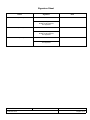
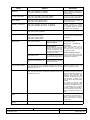
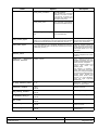
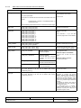
Amendment History
Issue
Description
Date
ECP No.
0.1
First draft
2004-11-09
-
0.2
Changes to driver installation
2004-11-24
-
0.3
Changed driver distribution table
2004-11-26
-
1.0
Baselined document
2004-12-20
-
1.1
Implemented ECP, made references to adapters more
generic
2006-06-29
CCII/HSS8/6-ECP/025
1.2
Improve document naming conventions
2009-08-22
CCII/HSS/6-ECP/042
CCII/HSS8/6-MAN/003
CH8MAN03.WPD
2009-08-22
Issue 1.2
Page iii of vii
Contents
1.
Scope . . . . . . . . . . . . . . . . . . . . . . . . . . . . . . . . . . . . . . . . . . . . . . . . . . . . . . . . . . . . . . . . . . . 1
1.1
1.2
1.3
2.
Identification . . . . . . . . . . . . . . . . . . . . . . . . . . . . . . . . . . . . . . . . . . . . . . . . . . . . . . . . . . . . . . . . . . . . . . . . . 1
System Overview . . . . . . . . . . . . . . . . . . . . . . . . . . . . . . . . . . . . . . . . . . . . . . . . . . . . . . . . . . . . . . . . . . . . . 1
Document Overview . . . . . . . . . . . . . . . . . . . . . . . . . . . . . . . . . . . . . . . . . . . . . . . . . . . . . . . . . . . . . . . . . . . 1
Applicable and Reference Documents . . . . . . . . . . . . . . . . . . . . . . . . . . . . . . . . . . . . . . . . . 2
2.1
2.2
Applicable Documents . . . . . . . . . . . . . . . . . . . . . . . . . . . . . . . . . . . . . . . . . . . . . . . . . . . . . . . . . . . . . . . . . 2
Reference Documents . . . . . . . . . . . . . . . . . . . . . . . . . . . . . . . . . . . . . . . . . . . . . . . . . . . . . . . . . . . . . . . . . 2
3.
HSS8 Linux Software Driver Distribution . . . . . . . . . . . . . . . . . . . . . . . . . . . . . . . . . . . . . . 3
4.
Installation Procedure . . . . . . . . . . . . . . . . . . . . . . . . . . . . . . . . . . . . . . . . . . . . . . . . . . . . . . 4
4.1
4.2
5.
Using the HSS8 Linux Software Driver . . . . . . . . . . . . . . . . . . . . . . . . . . . . . . . . . . . . . . . . 5
5.1
5.2
5.3
5.4
5.5
5.6
5.7
5.8
5.9
5.10
5.11
6.
Opening of Devices . . . . . . . . . . . . . . . . . . . . . . . . . . . . . . . . . . . . . . . . . . . . . . . . . . . . . . . . . . . . . . . . . . . 5
Configuring the Channels . . . . . . . . . . . . . . . . . . . . . . . . . . . . . . . . . . . . . . . . . . . . . . . . . . . . . . . . . . . . . . 5
Adding Receive Call-back Function . . . . . . . . . . . . . . . . . . . . . . . . . . . . . . . . . . . . . . . . . . . . . . . . . . . . . . . 6
Reading in Received Data . . . . . . . . . . . . . . . . . . . . . . . . . . . . . . . . . . . . . . . . . . . . . . . . . . . . . . . . . . . . . . 6
Writing Data . . . . . . . . . . . . . . . . . . . . . . . . . . . . . . . . . . . . . . . . . . . . . . . . . . . . . . . . . . . . . . . . . . . . . . . . . 7
Closing the Devices . . . . . . . . . . . . . . . . . . . . . . . . . . . . . . . . . . . . . . . . . . . . . . . . . . . . . . . . . . . . . . . . . . . 7
Obtaining the Current Host and Firmware Version Number . . . . . . . . . . . . . . . . . . . . . . . . . . . . . . . . . . . . 7
HSS8 Built-in Tests (BITs) . . . . . . . . . . . . . . . . . . . . . . . . . . . . . . . . . . . . . . . . . . . . . . . . . . . . . . . . . . . . . . 7
Enable / Disable Power-On-Self Tests . . . . . . . . . . . . . . . . . . . . . . . . . . . . . . . . . . . . . . . . . . . . . . . . . . . . 8
Return POST Status . . . . . . . . . . . . . . . . . . . . . . . . . . . . . . . . . . . . . . . . . . . . . . . . . . . . . . . . . . . . . . . . . . 8
Return Adapter Type . . . . . . . . . . . . . . . . . . . . . . . . . . . . . . . . . . . . . . . . . . . . . . . . . . . . . . . . . . . . . . . . . . 8
HSS8 Linux Software Driver Interface . . . . . . . . . . . . . . . . . . . . . . . . . . . . . . . . . . . . . . . . 10
6.1
6.2
6.3
7.
Compiling the HSS8 Linux Software Driver Module . . . . . . . . . . . . . . . . . . . . . . . . . . . . . . . . . . . . . . . . . . 4
Loading the HSS8 Linux Software Driver . . . . . . . . . . . . . . . . . . . . . . . . . . . . . . . . . . . . . . . . . . . . . . . . . . 4
HSS8 Linux Software Driver System Calls . . . . . . . . . . . . . . . . . . . . . . . . . . . . . . . . . . . . . . . . . . . . . . . . 10
6.1.1 Open System Call . . . . . . . . . . . . . . . . . . . . . . . . . . . . . . . . . . . . . . . . . . . . . . . . . . . . . . . . . . . . . 10
6.1.2 Close System Call . . . . . . . . . . . . . . . . . . . . . . . . . . . . . . . . . . . . . . . . . . . . . . . . . . . . . . . . . . . . 11
6.1.3 Read System Call . . . . . . . . . . . . . . . . . . . . . . . . . . . . . . . . . . . . . . . . . . . . . . . . . . . . . . . . . . . . . 11
6.1.4 Write System Call . . . . . . . . . . . . . . . . . . . . . . . . . . . . . . . . . . . . . . . . . . . . . . . . . . . . . . . . . . . . . 12
6.1.5 Ioctl System Call . . . . . . . . . . . . . . . . . . . . . . . . . . . . . . . . . . . . . . . . . . . . . . . . . . . . . . . . . . . . . . 13
HSS8 BIT Data Structures . . . . . . . . . . . . . . . . . . . . . . . . . . . . . . . . . . . . . . . . . . . . . . . . . . . . . . . . . . . . . 14
Protocol Data Structures . . . . . . . . . . . . . . . . . . . . . . . . . . . . . . . . . . . . . . . . . . . . . . . . . . . . . . . . . . . . . . 15
6.3.1 UART Mode . . . . . . . . . . . . . . . . . . . . . . . . . . . . . . . . . . . . . . . . . . . . . . . . . . . . . . . . . . . . . . . . . 16
6.3.1.1
UART Protocol Information Structure . . . . . . . . . . . . . . . . . . . . . . . . . . . . . . . . . . . . . . 16
6.3.1.2
UART Protocol Information Structure Members . . . . . . . . . . . . . . . . . . . . . . . . . . . . . . 17
6.3.2 HDLC Mode . . . . . . . . . . . . . . . . . . . . . . . . . . . . . . . . . . . . . . . . . . . . . . . . . . . . . . . . . . . . . . . . . 20
6.3.2.1
HDLC Protocol Information Structure . . . . . . . . . . . . . . . . . . . . . . . . . . . . . . . . . . . . . . 20
6.3.2.2
HDLC Protocol Information Structure Members . . . . . . . . . . . . . . . . . . . . . . . . . . . . . . 21
6.3.2.3
Preamble Requirements . . . . . . . . . . . . . . . . . . . . . . . . . . . . . . . . . . . . . . . . . . . . . . . 23
6.3.3 BISYNC Mode . . . . . . . . . . . . . . . . . . . . . . . . . . . . . . . . . . . . . . . . . . . . . . . . . . . . . . . . . . . . . . . 24
6.3.3.1
BISYNC Protocol Information Structure . . . . . . . . . . . . . . . . . . . . . . . . . . . . . . . . . . . . 24
6.3.3.2
BISYNC Protocol Information Structure Members . . . . . . . . . . . . . . . . . . . . . . . . . . . . 25
6.3.4 SMC UART Mode . . . . . . . . . . . . . . . . . . . . . . . . . . . . . . . . . . . . . . . . . . . . . . . . . . . . . . . . . . . . . 29
6.3.4.1
SMC UART Protocol Information Structure . . . . . . . . . . . . . . . . . . . . . . . . . . . . . . . . . 29
6.3.4.2
SMC UART Protocol Information Structure Members . . . . . . . . . . . . . . . . . . . . . . . . . 30
Getting Started . . . . . . . . . . . . . . . . . . . . . . . . . . . . . . . . . . . . . . . . . . . . . . . . . . . . . . . . . . . 31
CCII/HSS8/6-MAN/003
CH8MAN03.WPD
2009-08-22
Issue 1.2
Page iv of vii
8.
Contact Details . . . . . . . . . . . . . . . . . . . . . . . . . . . . . . . . . . . . . . . . . . . . . . . . . . . . . . . . . . . 32
8.1
8.2
8.3
8.4
8.5
1.
Scope . . . . . . . . . . . . . . . . . . . . . . . . . . . . . . . . . . . . . . . . . . . . . . . . . . . . . . . . . . . . . . . . . . . 1
1.1
1.2
1.3
2.
Contact Person . . . . . . . . . . . . . . . . . . . . . . . . . . . . . . . . . . . . . . . . . . . . . . . . . . . . . . . . . . . . . . . . . . . . . 32
Physical Address . . . . . . . . . . . . . . . . . . . . . . . . . . . . . . . . . . . . . . . . . . . . . . . . . . . . . . . . . . . . . . . . . . . . 32
Postal Address . . . . . . . . . . . . . . . . . . . . . . . . . . . . . . . . . . . . . . . . . . . . . . . . . . . . . . . . . . . . . . . . . . . . . . 32
Voice and Electronic Contacts . . . . . . . . . . . . . . . . . . . . . . . . . . . . . . . . . . . . . . . . . . . . . . . . . . . . . . . . . . 32
Product Support . . . . . . . . . . . . . . . . . . . . . . . . . . . . . . . . . . . . . . . . . . . . . . . . . . . . . . . . . . . . . . . . . . . . . 32
Identification . . . . . . . . . . . . . . . . . . . . . . . . . . . . . . . . . . . . . . . . . . . . . . . . . . . . . . . . . . . . . . . . . . . . . . . . . 1
System Overview . . . . . . . . . . . . . . . . . . . . . . . . . . . . . . . . . . . . . . . . . . . . . . . . . . . . . . . . . . . . . . . . . . . . . 1
Document Overview . . . . . . . . . . . . . . . . . . . . . . . . . . . . . . . . . . . . . . . . . . . . . . . . . . . . . . . . . . . . . . . . . . . 1
Applicable and Reference Documents . . . . . . . . . . . . . . . . . . . . . . . . . . . . . . . . . . . . . . . . . 2
2.1
2.2
Applicable Documents . . . . . . . . . . . . . . . . . . . . . . . . . . . . . . . . . . . . . . . . . . . . . . . . . . . . . . . . . . . . . . . . . 2
Reference Documents . . . . . . . . . . . . . . . . . . . . . . . . . . . . . . . . . . . . . . . . . . . . . . . . . . . . . . . . . . . . . . . . . 2
3.
HSS8 Linux Software Driver Distribution . . . . . . . . . . . . . . . . . . . . . . . . . . . . . . . . . . . . . . 3
4.
Installation Procedure . . . . . . . . . . . . . . . . . . . . . . . . . . . . . . . . . . . . . . . . . . . . . . . . . . . . . . 4
4.1
4.2
5.
Using the HSS8 Linux Software Driver . . . . . . . . . . . . . . . . . . . . . . . . . . . . . . . . . . . . . . . . 5
5.1
5.2
5.3
5.4
5.5
5.6
5.7
5.8
5.9
5.10
5.11
6.
Compiling the HSS8 Linux Software Driver Module . . . . . . . . . . . . . . . . . . . . . . . . . . . . . . . . . . . . . . . . . . 4
Loading the HSS8 Linux Software Driver . . . . . . . . . . . . . . . . . . . . . . . . . . . . . . . . . . . . . . . . . . . . . . . . . . 4
Opening of Devices . . . . . . . . . . . . . . . . . . . . . . . . . . . . . . . . . . . . . . . . . . . . . . . . . . . . . . . . . . . . . . . . . . . 5
Configuring the Channels . . . . . . . . . . . . . . . . . . . . . . . . . . . . . . . . . . . . . . . . . . . . . . . . . . . . . . . . . . . . . . 5
Adding Receive Call-back Function . . . . . . . . . . . . . . . . . . . . . . . . . . . . . . . . . . . . . . . . . . . . . . . . . . . . . . . 6
Reading in Received Data . . . . . . . . . . . . . . . . . . . . . . . . . . . . . . . . . . . . . . . . . . . . . . . . . . . . . . . . . . . . . . 6
Writing Data . . . . . . . . . . . . . . . . . . . . . . . . . . . . . . . . . . . . . . . . . . . . . . . . . . . . . . . . . . . . . . . . . . . . . . . . . 7
Closing the Devices . . . . . . . . . . . . . . . . . . . . . . . . . . . . . . . . . . . . . . . . . . . . . . . . . . . . . . . . . . . . . . . . . . . 7
Obtaining the Current Host and Firmware Version Number . . . . . . . . . . . . . . . . . . . . . . . . . . . . . . . . . . . . 7
HSS8 Built-in Tests (BITs) . . . . . . . . . . . . . . . . . . . . . . . . . . . . . . . . . . . . . . . . . . . . . . . . . . . . . . . . . . . . . . 7
Enable / Disable Power-On-Self Tests . . . . . . . . . . . . . . . . . . . . . . . . . . . . . . . . . . . . . . . . . . . . . . . . . . . . 8
Return POST Status . . . . . . . . . . . . . . . . . . . . . . . . . . . . . . . . . . . . . . . . . . . . . . . . . . . . . . . . . . . . . . . . . . 8
Return Adapter Type . . . . . . . . . . . . . . . . . . . . . . . . . . . . . . . . . . . . . . . . . . . . . . . . . . . . . . . . . . . . . . . . . . 8
HSS8 Linux Software Driver Interface . . . . . . . . . . . . . . . . . . . . . . . . . . . . . . . . . . . . . . . . 10
6.1
6.2
6.3
HSS8 Linux Software Driver System Calls . . . . . . . . . . . . . . . . . . . . . . . . . . . . . . . . . . . . . . . . . . . . . . . . 10
6.1.1 Open System Call . . . . . . . . . . . . . . . . . . . . . . . . . . . . . . . . . . . . . . . . . . . . . . . . . . . . . . . . . . . . . 10
6.1.2 Close System Call . . . . . . . . . . . . . . . . . . . . . . . . . . . . . . . . . . . . . . . . . . . . . . . . . . . . . . . . . . . . 11
6.1.3 Read System Call . . . . . . . . . . . . . . . . . . . . . . . . . . . . . . . . . . . . . . . . . . . . . . . . . . . . . . . . . . . . . 11
6.1.4 Write System Call . . . . . . . . . . . . . . . . . . . . . . . . . . . . . . . . . . . . . . . . . . . . . . . . . . . . . . . . . . . . . 12
6.1.5 Ioctl System Call . . . . . . . . . . . . . . . . . . . . . . . . . . . . . . . . . . . . . . . . . . . . . . . . . . . . . . . . . . . . . . 13
HSS8 BIT Data Structures . . . . . . . . . . . . . . . . . . . . . . . . . . . . . . . . . . . . . . . . . . . . . . . . . . . . . . . . . . . . . 14
Protocol Data Structures . . . . . . . . . . . . . . . . . . . . . . . . . . . . . . . . . . . . . . . . . . . . . . . . . . . . . . . . . . . . . . 15
6.3.1 UART Mode . . . . . . . . . . . . . . . . . . . . . . . . . . . . . . . . . . . . . . . . . . . . . . . . . . . . . . . . . . . . . . . . . 16
6.3.1.1
UART Protocol Information Structure . . . . . . . . . . . . . . . . . . . . . . . . . . . . . . . . . . . . . . 16
6.3.1.2
UART Protocol Information Structure Members . . . . . . . . . . . . . . . . . . . . . . . . . . . . . . 17
6.3.2 HDLC Mode . . . . . . . . . . . . . . . . . . . . . . . . . . . . . . . . . . . . . . . . . . . . . . . . . . . . . . . . . . . . . . . . . 20
6.3.2.1
HDLC Protocol Information Structure . . . . . . . . . . . . . . . . . . . . . . . . . . . . . . . . . . . . . . 20
6.3.2.2
HDLC Protocol Information Structure Members . . . . . . . . . . . . . . . . . . . . . . . . . . . . . . 21
6.3.2.3
Preamble Requirements . . . . . . . . . . . . . . . . . . . . . . . . . . . . . . . . . . . . . . . . . . . . . . . 23
6.3.3 BISYNC Mode . . . . . . . . . . . . . . . . . . . . . . . . . . . . . . . . . . . . . . . . . . . . . . . . . . . . . . . . . . . . . . . 24
6.3.3.1
BISYNC Protocol Information Structure . . . . . . . . . . . . . . . . . . . . . . . . . . . . . . . . . . . . 24
6.3.3.2
BISYNC Protocol Information Structure Members . . . . . . . . . . . . . . . . . . . . . . . . . . . . 25
6.3.4 SMC UART Mode . . . . . . . . . . . . . . . . . . . . . . . . . . . . . . . . . . . . . . . . . . . . . . . . . . . . . . . . . . . . . 29
6.3.4.1
SMC UART Protocol Information Structure . . . . . . . . . . . . . . . . . . . . . . . . . . . . . . . . . 29
CCII/HSS8/6-MAN/003
CH8MAN03.WPD
2009-08-22
Issue 1.2
Page v of vii
6.3.4.2
SMC UART Protocol Information Structure Members . . . . . . . . . . . . . . . . . . . . . . . . . 30
7.
Getting Started . . . . . . . . . . . . . . . . . . . . . . . . . . . . . . . . . . . . . . . . . . . . . . . . . . . . . . . . . . . 31
8.
Contact Details . . . . . . . . . . . . . . . . . . . . . . . . . . . . . . . . . . . . . . . . . . . . . . . . . . . . . . . . . . . 32
8.1
8.2
8.3
8.4
8.5
Contact Person . . . . . . . . . . . . . . . . . . . . . . . . . . . . . . . . . . . . . . . . . . . . . . . . . . . . . . . . . . . . . . . . . . . . . 32
Physical Address . . . . . . . . . . . . . . . . . . . . . . . . . . . . . . . . . . . . . . . . . . . . . . . . . . . . . . . . . . . . . . . . . . . . 32
Postal Address . . . . . . . . . . . . . . . . . . . . . . . . . . . . . . . . . . . . . . . . . . . . . . . . . . . . . . . . . . . . . . . . . . . . . . 32
Voice and Electronic Contacts . . . . . . . . . . . . . . . . . . . . . . . . . . . . . . . . . . . . . . . . . . . . . . . . . . . . . . . . . . 32
Product Support . . . . . . . . . . . . . . . . . . . . . . . . . . . . . . . . . . . . . . . . . . . . . . . . . . . . . . . . . . . . . . . . . . . . . 32
CCII/HSS8/6-MAN/003
CH8MAN03.WPD
2009-08-22
Issue 1.2
Page vi of vii
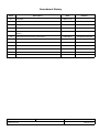
Abbreviations and Acronyms
API
Application Program Interface
BCS
Block Check Sequence
BISYNC
Binary Synchronous Communication
BIT
Built-in Test
bit/s
bits per second
BRG
Baud Rate Generator
CD
Carrier Detect
CRC
Cyclic Redundancy Check
CTS
Clear to Send
DLE
Data Link Escape
DPLL
Digital Phase-Locked Loop
EEPROM
Electrically Erasable Programable Read Only Memory
FIFO
First In First Out
HDLC
High Level Data Link Control
HSS4NG
4-Channel High-Speed Serial Adapter
HSS8
8-Channel High-Speed Serial
I/O
Input / Output
LED
Light Emitting Diode
MHz
MegaHertz
NRZ
Non-Return-to-Zero
NRZI
Non-Return-to-Zero-Inverted
POST
Power-On-Self Test
RAM
Random Access Memory
RTS
Request to Send
RxD
Receive Data
SCC
Serial Communications Controller
SDLC
Synchronous Data Link control
SMC
Serial Management Controller
SYNC
Synchronisation
TxD
Transmit Data
UART
Universal Asynchronous Receiver/Transmitter
CCII/HSS8/6-MAN/003
CH8MAN03.WPD
2009-08-22
Issue 1.2
Page vii of vii
1.
Scope
1.1
Identification
This document is the user manual for the HSS8 Linux Software Driver for the C²I² Systems 8-channel
High-Speed Serial (HSS8) Adapter and the 4-Channel High-Speed Serial Adapter (HSS4NG). The HSS4NG
is based on a stripped down HSS8 Adapter and as such this manual applies, except that only SCC channels
0 - 3 and SMC channels 8 - 9 will be available.
1.2
System Overview
The HSS8 Adapter provides eight channels of simultaneous, high-speed, bi-directional serial communications
and an additional four channels of lower-speed serial communications. The eight high-speed channels are
jumper configurable (on a per channel basis) for RS-232 or RS-422/485 drivers while the lower-speed channels
have RS-232 drivers only.
The HSS8 Linux Software Driver is a low level, device-dependent interface for transferring data over a
C²I² Systems HSS8 Adapter. The HSS8 Linux Software Driver binaries are provided with explicit installation
instructions.
1.3
Document Overview
This document gives an overview of the HSS8 Linux Software Driver installation procedure and its Software
Driver Interface.
CCII/HSS8/6-MAN/003
CH8MAN03.WPD
2009-08-20
Issue 1.2
Page 1 of 32
2.
Applicable and Reference Documents
2.1
Applicable Documents
2.1.1
MPC8260 PowerQUICC II Family Reference Manual, MPC8260UM/D, rev. 1, dated May 2003.
2.1.2
CCII/HSS8/6-MAN/001, Hardware Reference Manual for the 4-Channel New Generation and 8-Channel
High-Speed Serial I/O Adapters.
2.2
Reference Documents
None.
CCII/HSS8/6-MAN/003
CH8MAN03.WPD
2009-08-20
Issue 1.2
Page 2 of 32
3.
HSS8 Linux Software Driver Distribution
The HSS8 Linux Software Driver software distribution consists of (at least) the following files :
ccHss8LnxSrcV<version>.tar.gz
HSS8 Linux Software Driver source code.
<version> - Software version is a 3 digit integer :
•
1st digit : version number
•
2nd digit : revision number
•
3rd digit : beta number
ccHss8EmbV<version>.hex
HSS8 firmware.
<version> - Software version is a 3 digit integer :
•
1st digit : version number
•
2nd digit : revision number
•
3rd digit : beta number
flashprog
Flash update utility.
hss8Readme.txt
General information and installation notes.
hss8Release_emb.txt,
hss8Release_linux.txt
Release notes and revision history :
Please check this file for information on the latest updates.
ccHss8Test.c
Sample C code for accessing the HSS8 Linux Software Driver.
hss8Flash.txt
Procedure for updating the firmware if required.
hss8Test.txt
Test procedure for verifying HSS8 Linux Software Driver and firmware.
CCII/HSS8/6-MAN/003
CH8MAN03.WPD
2009-08-20
Issue 1.2
Page 3 of 32
4.
Installation Procedure
This paragraph describes the installation procedure for the HSS8 Linux Software Driver.
4.1
Compiling the HSS8 Linux Software Driver Module
Unpack the HSS8 Linux Software Driver.source file using : tar -xvzf ccHss8LnxSrcV<version>.tar.gz. A
directory named ‘hss8' will be created. Change to ‘hss8/lnx/builds/host/linux’ to build the HSS8 Linux Software
Driver module by typing the following commands :
make clean
make all
Note :
4.2
The HSS8 Linux Software Driver is only supported on Linux kernel versions 2.6 and upwards.
Loading the HSS8 Linux Software Driver
Within the ‘hss8/lnx/builds/host/linux’‘ directory are 3 script files to help load the HSS8 Linux Software Driver.
The HSS8 Linux Software Driver may be loaded in two ways :
C
Using script files (hss8_load/hss8_unload), which can be invoked from the system’s rc.local file or be called
manually whenever the module is needed.
C
Using an init script (hss8_init), to be placed in the directory the Linux distribution uses to load init scripts,
i.e. /etc/init.d or /etc/rc.d/init.d. The HSS8 Linux Software Driver module should be located in the module
directory of the kernel : /lib/modules/[kernel version]/kernel/drivers/misc.
The HSS8 Linux Software Driver supports up to four HSS8 Adapters on one host system. The script files will
detect all HSS8 Adapters present and setup all devices. All HSS8 devices are created in /dev and have the
following naming convention :
hss8_<X>_<Y>
X
Y
- [A - D] indicating which HSS8 Adapter this device belongs to.
- [0 - 11] indicating the channel number of the HSS8 Adapter.
The file /proc/devices lists each HSS8 Adapter and its corresponding major number under the character devices
section. Each devices minor number corresponds to the channel number of the HSS8 Adapter.
Note :
In order to load the HSS8 Linux Software Driver, the user must have root privileges.
CCII/HSS8/6-MAN/003
CH8MAN03.WPD
2009-08-20
Issue 1.2
Page 4 of 32
5.
Using the HSS8 Linux Software Driver
The HSS8 Linux Software Driver is a character driver. Each channel on the HSS8 Adapter is available as a
separate device on Linux and can be accessed with the following file-handling system calls :
5.1
C
open
-
open the device (or corresponding channel on the HSS8 Adapter) for reading and writing.
C
close
-
close the device (or corresponding channel on the HSS8 Adapter) for reading and writing.
C
read
-
read from the device (or receive data on the specific channel on the HSS8 Adapter).
C
write
-
write to the device (or send data on the specific channel on the HSS8 Adapter).
C
ioctl
-
setup the various protocols (UART, HDLC, BISYNC).
Opening of Devices
Before any device may be accessed, it must be opened with the open system call. The open system call returns
a file descriptor, which is used as a handle to the device for subsequent accesses.
The HSS8 Linux Software Driver allows only one instance of the device to be open at any time. Hence
subsequent open calls will return an error. The user application should share the file descriptor between
processes to access the device at any time.
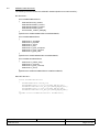
Example :
For device /dev/hss8_A_0 :
fd = open("/dev/hss8_A_0", O_RDWR);
if(fd < 0)
{
printf("Error opening device: %s - %s\n", "/dev/hss8_A_”, strerror(errno));
return 1;
}
5.2
Configuring the Channels
The HSS8 Adapter has eight Serial Communications Controllers (SCCs) [Channels A - H] that support UART,
HDLC/SDLC and BISYNC protocols, and four Serial Management Controllers (SMC's) [Channels I - L] that
support only asynchronous UART. Devices hss8_[A - D]_[0 - 7] correspond to Channels A - H and devices
hss8_[A - D]_[8 - 11] to Channels I - L.
After a HSS8 device has been opened, the user must first set the default configuration for each of the channels.
To set the configuration of a channel, a protocol-specific information structure is used. Examples of the required
structure is given in ccHss8Test.c (for the UART protocol) and can be used as a starting point.
The structures allow the user to set all the protocol-specific options available on the HSS8 communication
controller chip (the MPC8260 PowerQUICC II™). For available options for each of the structure fields,
see [2.1.1].
The ioctl system call is used to feed the protocol specific structure to the HSS8 Linux Software Driver.
Example :
Set device with file descriptor fd to UART mode :
/* Set initial SCC port configuration */
ioctl(fd, HSS8_IOC_SET_PORT_CONFIG, &uart_info);
CCII/HSS8/6-MAN/003
CH8MAN03.WPD
2009-08-20
Issue 1.2
Page 5 of 32
5.3
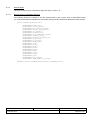
Adding Receive Call-back Function
The HSS8 Linux Software Driver is able to notify the user if data is available to read. This is accomplished with
asynchronous notification and is enabled as follows :
C
C
C
C
C
The user program needs to specify a process as the owner of the device. This is necessary so that the
kernel knows which process to notify of an event.
For the Call-back function to determine the file descriptor that caused this signal, the user program must
set the SIGIO flag in the device by means of the F_SETSIG fcntl command.
To actually enable asynchronous notification, the user program must set the FASYNC flag in the device
by means of the F_SETFL fcntl command.
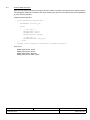
The above steps are implemented in software as follows :
#include <fcntl.h>
/* setup this process as the owner of the file descriptor */
fcntl(fd, F_SETOWN, getpid());
/* set the SIGIO signal */
fcntl(fd, F_SETSIG, SIGIO);
/* setup async notification */
fcntl(fd, F_SETFL, fcntl(fd, F_GETFL) | FASYNC);
The Call-back function may be setup as follows :
#include <signal.h>
void hss8Test_rx_callback(int signo, siginfo_t *siginfo, void *what)
{
/* read data */
read(siginfo->si_fd, rx_data, 10);
}
...
...
struct sigaction action;
/* setup rx callback */
memset(&action, 0, sizeof(action));
action.sa_sigaction = hss8Test_rx_callback;
action.sa_flags = SA_SIGINFO | SA_NOMASK;
sigaction(SIGIO, &action, NULL);
Note :
5.4
For more information on the sigaction system call, consult its man page.
Reading in Received Data
The read system call will return the number of bytes received on the specific channel of the HSS8 Adapter. If
less data is available than the application requested, this amount will be returned immediately.
If no data is present, the read system call will block by default until at least one byte is there. If the flag
O_NONBLOCK has been specified and no data is present, the read system call will return immediately with
a return value of -EAGAIN.
CCII/HSS8/6-MAN/003
CH8MAN03.WPD
2009-08-20
Issue 1.2
Page 6 of 32
Example :
Read 10 bytes from device with file descriptor fd :
unsigned char rx_data[10];
read(fd, rx_data, 10);
5.5
Writing Data
The write system call writes data to be send on the specific channel of the HSS8 Adapter. The return value,
if the call was successful, is the number of bytes written.
Blocking is not supported with the write system call. If the specific channel of the HSS8 Adapter cannot accept
anymore data, the write system call will return immediately with a return value of -EBUSY.
Example :
Write 4 bytes to device with file descriptor fd :
unsigned char tx_data[4] = {0xAA, 0xBB, 0xCC, 0xDD};
write(fd, tx_data, 4);
5.6
Closing the Devices
Devices are closed with the close system call. Once closed, the corresponding channel of the device will reject
all incoming data. This data will not be available once the device is re-opened.
5.7
Obtaining the Current Host and Firmware Version Number
The HSS8 Linux Software Driver, engine version and the firmware version may be obtained with the ioctl
system call. This information is available on all devices per HSS8 Adapter.
char host_string[HSS8_VERSION_STRING_LENGTH] = {0};
char engine_string[HSS8_VERSION_STRING_LENGTH] = {0};
char firmware_string[HSS8_VERSION_STRING_LENGTH] = {0};
status = ioctl(fd, HSS8_IOC_ENGINE_VERSION_GET, engine_string);
if(status != 0)
{
printf("Could not get current engine version.\n");
}
status = ioctl(fd, HSS8_IOC_EMBEDDED_VERSION_GET, firmware_string);
if(status != 0)
{
printf("Could not get current firmware version.\n");
}
status = ioctl(fd, HSS8_IOC_HOST_VERSION_GET, host_string);
if(status != 0)
{
printf("Could not get current host version.\n");
}
printf("Current driver:
V%s\n", host_string);
printf("Current engine:
V%s\n", engine_string);
printf("Current firmware: V%s\n\n", firmware_string);
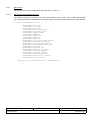
5.8
HSS8 Built-in Tests (BITs)
The structure hss8BitInfo defined in hss8ControlIfc.h stores each channel's statistics : e.g. how many
bytes / packets have been accepted / rejected / sent / received and how many errors were reported. The ioctl
system call fills in the structure with the latest data and returns it to the user application. This information is
available on all devices per HSS8 Adapter.
CCII/HSS8/6-MAN/003
CH8MAN03.WPD
2009-08-20
Issue 1.2
Page 7 of 32
Example :
Obtaining each channel's statistics :
hss8BitInfo bit_info;
ioctl(fd, HSS8_IOC_BIT_GET, &bit_info);
To clear the counters on the HSS8 Adapter, use the following ioctl command :
ioctl(fd, HSS8_IOC_BIT_CLEAR);
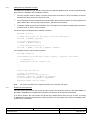
5.9
Enable / Disable Power-On-Self Tests
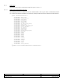
Various Power-On-Self Tests (POSTs) may be enabled/disabled via the ioctl system call. The following macros
(see hss8ControlIfc.h) define the tests :
!
!
!
!
HSS8_POST_RAM_DATA_ENABLE
HSS8_POST_RAM_ADDR_ENABLE
HSS8_POST_RAM_DEV_ENABLE
HSS8_POST_KERNEL_CRC_ENABLE
- Test the onboard RAM data bus.
- Test the onboard RAM address bus.
- Test the onboard RAM devices.
- Test the embedded firmware CRC.
To disable all tests, specify zero.
Note :
Every time the HSS8 Adapter starts up, the specified tests are run. If the user doesn’t require these
tests anymore, they need to be disabled again. By default, no tests are specified.
Example :
Enable all POST tests :
char post_tests = HSS8_POST_RAM_DATA_ENABLE | HSS8_POST_RAM_ADDR_ENABLE |
HSS8_POST_RAM_DEV_ENABLE | HSS8_POST_KERNEL_CRC_ENABLE;
ioctl(fd, HSS8_IOC_POST_ENABLE, &post_tests);
5.10
Return POST Status
The POST status may be obtained via the ioctl system call. The following macros (see hss8ControlIfc.h) define
the status :
!
!
!
!
!
!
!
!
!
HSS8_OK
HSS8_EEPROM_UPDATE
HSS8_EEPROM_ERROR
HSS8_RAM_DATA_ERROR
HSS8_RAM_ADDR_ERROR
HSS8_RAM_DEVICE_ERROR
HSS8_FLASH_MAGIC_ERROR
HSS8_FLASH_KERNEL_CRC_ERROR
HSS8_SLAVE_PowerQUICC_II_FAIL
Example :
-
All tests passed.
EEPROM was corrupt and was reprogrammed.
EEPROM read / write error.
RAM databus error.
RAM addressbus error.
RAM device error.
Flash magic number corrupt.
Flash CRC error.
Second PowerQUICC II processor failed to start up.
Get POST status :
char post_status = 0;
ioctl(fd, HSS8_IOC_POST_STATUS, &post_status);
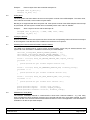
5.11
Return Adapter Type
The adapter type may be obtained via the ioctl system call. The return value will be either 4 or 8, describing a
4-channel (four SCCs and two SMCs available) or 8-channel (eight SCCs and four SMCs available) adapter.
When a 4-channel adapter is present, only the following devices are valid : hss8_[A - D]_[0 - 3] (four SCC
channels) and hss8_[A - D]_[8 - 9] (two SMC ports). All other devices, although visible in /dev, will return an
error (-ENODEV) when accessed.
CCII/HSS8/6-MAN/003
CH8MAN03.WPD
2009-08-20
Issue 1.2
Page 8 of 32
Example :
Get adapter type :
char adapter_type = 0;
ioctl(fd, HSS8_IOC_ADAPTER_TYPE, &adapter_type);
CCII/HSS8/6-MAN/003
CH8MAN03.WPD
2009-08-20
Issue 1.2
Page 9 of 32
6.
HSS8 Linux Software Driver Interface
The HSS8 Linux Software Driver source contains the following header files (in ‘hss8/lnx/src/h’), which should
always be included in user applications :
C
hss8LnxDriver.h
-
IOCTL command definitions.
C
hss8Defs.h
-
HSS8 type definitions.
C
hss8HostDriver.h -
Of only importance for the HSS8 Linux Software Driver are the defines of the HSS8
adapter. The function declarations may be ignored, as they are not applicable to the
HSS8 Linux Software Driver.
C
hss8ControlIfc.h
-
Definition of structures and types for all protocols available on the HSS8 Adapter.
C
other header files -
Other header files are only used to compile the software driver module and are not
necessary for user applications.
6.1
HSS8 Linux Software Driver System Calls
6.1.1
Open System Call
Function :
open
Purpose :
Open the HSS8 device (or port) and return a file descriptor.
Arguments :
<pathname>
-
<flags>
-
The path and name of device. Usually “/dev/hss8_X_Y”, where X = [A - D] and
Y = [0 - 11].
Always O_RDWR. If no blocking is desired, specify O_NONBLOCK as well
(bitwise-ORed with previous parameter). Do not specify O_ASYNC here, rather
setup asynchronous notification as described in 5.3.
-
File descriptor.
Error occurred.
-
Incorrect device specified or device cannot be found.
The device is already open or the adapter is busy.
The open system call was interrupted by a signal.
Returns :
fd
-1
Errors :
-ENODEV
-EBUSY
-EINTR
#include <sys/types.h>
#include <sys/stat.h>
#include <fcntl.h>
int open(const char *pathname, int flags);
CCII/HSS8/6-MAN/003
CH8MAN03.WPD
2009-08-20
Issue 1.2
Page 10 of 32
6.1.2
Close System Call
Function :
close
Purpose :
Close the HSS8 device (or port) and release the file descriptor.
Arguments :
<fd>
-
The file descriptor to be closed.
-
On success.
Error occurred.
-
Incorrect file descriptor specified.
Incorrect device specified or device cannot be found.
The adapter is busy.
The close system call was interrupted by a signal.
Returns :
0
-1
Errors :
-EBADF
-ENODEV
-EBUSY
-EINTR
#include <unistd.h>
int close(int fd);
6.1.3
Read System Call
Function :
read
Purpose :
Read from device (or read in received data from port).
Arguments :
<fd>
<buf>
<count>
-
File descriptor to read from.
Buffer to read bytes into.
Number of bytes to read from device.
num_bytes
-
-1
-
Number of bytes read. This may be less than the bytes requested, which is not
an error. If zero, there are no bytes to read at present.
Error occurred.
Returns :
Errors :
-EBADF
-EFAULT
-EAGAIN
-
-EINTR
-
Incorrect file descriptor specified.
There was a problem copying data into the user specified buffer.
Non blocking has been specified and no data was immediately available for
reading.
The close system call was interrupted by a signal.
#include <unistd.h>
ssize_t read(int fd, void *buf, size_t count);
CCII/HSS8/6-MAN/003
CH8MAN03.WPD
2009-08-20
Issue 1.2
Page 11 of 32
6.1.4
Write System Call
Function :
write
Purpose :
Write to device (or send data on specific port).
Arguments :
<fd>
<buf>
<count>
-
File descriptor to write to.
Buffer containing the data to be written to device.
Number of bytes to write to device. May only be up to a maximum of 32 kBytes.
-
Number of bytes written. If zero, no bytes have been written.
Error occurred.
-
Incorrect file descriptor specified.
Incorrect device specified or device cannot be found.
The maximum number of bytes to be written has been exceeded.
There was a problem copying data from the user specified buffer.
The close system call was interrupted by a signal.
Returns :
num_bytes
-1
Errors :
-EBADF
-ENODEV
-EINVAL
-EFAULT
-EINTR
#include <unistd.h>
ssize_t write(int fd, const void *buf, size_t count);
CCII/HSS8/6-MAN/003
CH8MAN03.WPD
2009-08-20
Issue 1.2
Page 12 of 32
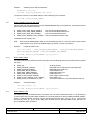
6.1.5
Ioctl System Call
Function :
ioctl
Purpose :
Configure the protocol of the device or obtain device specific information.
Arguments :
<fd>
<request>
-
File descriptor to configure.
Command to be performed. One of :
1.
2.
3.
4.
5.
6.
7.
8.
9.
10.
<...>
-
HSS8_IOC_SET_PORT_CONFIG
HSS8_IOC_GET_PORT_CONFIG
HSS8_IOC_BIT_CLEAR
HSS8_IOC_BIT_GET
HSS8_IOC_ENGINE_VERSION_GET
HSS8_IOC_EMBEDDED_VERSION_GET
HSS8_IOC_HOST_VERSION_GET
HSS8_IOC_POST_ENABLE
HSS8_IOC_POST_STATUS
HSS8_IOC_ADAPTER_TYPE
Command specific argument :
1.
2.
3.
4.
5.
6.
7.
8.
9.
10.
Initialised hss8ProtocolInfo structure.
Cleared hss8ProtocolInfo structure.
No argument.
Cleared hss8BitInfo structure.
char buffer.
char buffer.
char buffer.
char variable.
char variable.
char variable.
Returns :
0
-1
-
On success.
Error occurred.
-
Incorrect file descriptor specified.
Incorrect device specified or device cannot be found.
Incorrect protocol specified for specific device or port.
The command specific argument references an inaccessible memory area.
The specified request does not exist.
Internal temporary kernel memory allocation failed.
HSS8 Adapter may be busy.
Errors :
-EBADF
-ENODEV
-EINVAL
-EFAULT
-ENOTTY
-ENOMEM
-EBUSY
#include <sys/ioctl.h>
int ioctl(int fd, int request, ...);
CCII/HSS8/6-MAN/003
CH8MAN03.WPD
2009-08-20
Issue 1.2
Page 13 of 32
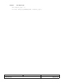
6.2
HSS8 BIT Data Structures
The following structures define the HSS8 BIT variables (defined in hss8ControlIfc.h) :
BIT Structures :
struct hss8BoardBitInfoStruct
{
hss8UINT32 board_number;
hss8UINT32 firmware_version;
hss8UINT32 firmware_revision;
hss8UINT32 firmware_beta;
char firmware_creation_date[30];
};
typedef struct hss8BoardBitInfoStruct hss8BoardBitInfo;
struct hss8SendBitInfoStruct
{
hss8Count nr_accepted;
hss8Count nr_rejected;
hss8Count nr_errors;
hss8Count nr_sent;
hss8Count nr_bytes_accepted;
hss8Count nr_bytes_rejected;
hss8Count nr_bytes_sent;
};
typedef struct hss8SendBitInfoStruct hss8SendBitInfo;
struct hss8ReceiveBitInfoStruct
{
hss8Count nr_buffers_busy;
hss8Count nr_received;
hss8Count nr_bytes_received;
hss8Count nr_errors;
};
typedef struct hss8ReceiveBitInfoStruct hss8ReceiveBitInfo;
Main BIT Structure :
struct hss8BitInfoStruct
{
hss8BoardBitInfo board_bit;
hss8SendBitInfo tx_scc_bit[HSS8_HW_NR_SCC];
hss8ReceiveBitInfo rx_scc_bit[HSS8_HW_NR_SCC];
hss8SendBitInfo tx_smc_bit[HSS8_HW_NR_SMC];
hss8ReceiveBitInfo rx_smc_bit[HSS8_HW_NR_SMC];
};
typedef struct hss8BitInfoStruct hss8BitInfo;
CCII/HSS8/6-MAN/003
CH8MAN03.WPD
2009-08-20
Issue 1.2
Page 14 of 32
6.3
Protocol Data Structures
Each protocol defines a protocol information structure used to configure a port with protocol specific options.
This paragraph details the information structures used by each protocol and explains the use and limitations
of every structure member.
hss8ProtocolInfo structure :
struct hss8ProtocolInfoStruct
{
hss8UINT32 protocol_id;
union
{
/* SCC info */
hss8UartInfo uart;
hss8HdlcInfo hdlc;
hss8BisyncInfo bisync;
/* SMC info */
hss8SmcUartInfo smc_uart;
} info;
};
typedef struct hss8ProtocolInfoStruct hss8ProtocolInfo;
protocol_id :
HSS8_PROTOCOL_UART
HSS8_PROTOCOL_HDLC
HSS8_PROTOCOL_BISYNC
HSS8_PROTOCOL_SMC_UART
CCII/HSS8/6-MAN/003
CH8MAN03.WPD
2009-08-20
Issue 1.2
Page 15 of 32
6.3.1
UART Mode
This protocol may only be used with the eight SCC ports : Ports A - H.
6.3.1.1
UART Protocol Information Structure
The following structure is defined in the file hss8ControlIfc.h and is given here in abbreviated format
(i.e. reserved and obsolete members are not shown). Always use the structure as defined in hss8ControlIfc.h.
struct hss8UartInfoStruct
{
hss8UINT32 baud_rate;
hss8UINT32 flow_control;
hss8UINT32 stop_bits;
hss8UINT32 data_bits;
hss8UINT32 uart_mode;
hss8UINT32 freeze_tx;
hss8UINT32 rx_zero_stop_bits;
hss8UINT32 sync_mode;
hss8UINT32 disable_rx_while_tx;
hss8UINT32 parity_enable;
hss8UINT32 rx_parity;
hss8UINT32 tx_parity;
hss8UINT32 diag_mode;
hss8UINT32 max_receive_bytes;
hss8UINT32 max_idl;
hss8UINT32 brkcr;
hss8UINT32 parec;
hss8UINT32 frmec;
hss8UINT32 nosec;
hss8UINT32 brkec;
hss8UINT32 uaddr1;
hss8UINT32 uaddr2;
hss8UINT32 toseq;
hss8UINT32 cc[8];
hss8UINT32 rccm;
hss8UINT32 clock_source;
};
typedef struct hss8UartInfoStruct hss8UartInfo;
CCII/HSS8/6-MAN/003
CH8MAN03.WPD
2009-08-20
Issue 1.2
Page 16 of 32
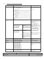
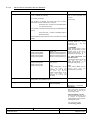
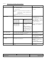
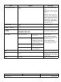
6.3.1.2
UART Protocol Information Structure Members
Name
baud_rate
Options
Description
1 200 - 1 Mbit/s (RS-232)
1 200 - 16 Mbit/s (RS-422/485)
Used to specify a single baud rate
for both transmitter and receiver.
Any values permissible.
Units in bit/s.
The equation to calculate the actual baud rate for asynchronous
UART is as follows :
Actual baud rate = 100 MHz / 16 / ROUND(100 MHz / 16 /
Desired baud rate)
The equation to calculate the actual baud rate for synchronous
UART is as follows :
Actual baud rate = 100 MHz / ROUND(100 MHz / Desired
baud rate)
Where ROUND() implies that the result is rounded to the nearest
integer.
clock_source
HSS8_CLOCK_DEFAULT
HSS8_CLOCK_DEFAULT
connects
Baud
Rate
Generators (BRGs) [1 - 4] to
Channels [A - D] and
Channels [E - H].
BRGs [1-4].
BRG1 for Channels [A and E]
BRG2 for Channels [B and F]
BRG3 for Channels [C and G]
BRG4 for Channels [D and H]
HSS8_CLOCK_BRG1
HSS8_CLOCK_BRG2
HSS8_CLOCK_BRG3
HSS8_CLOCK_BRG4
HSS8_CLOCK_EXT1
HSS8_CLOCK_EXT2
HSS8_CLOCK_EXT3
HSS8_CLOCK_EXT4
External Clocks connected on
CLK_IN Pins.
Note :
HSS8_CLOCK_EXT[1 - 2] can
only
be
used
for
Channel [A and B] and
[E
and
F],
while
HSS8_CLOCK_EXT[3 - 4] can
only
be
used
for
Channels [C and D] and
[G and H].
For synchronous UART :
When transmit clock is set to
HSS8_CLOCK_BRG[1 - 4], then
receive clock is still set to
HSS8_CLOCK_EXT[1 - 4] for
Channels [A - D] and [E - H].
For asynchronous UART :
Transmit and receive clocks can
be
set
to
one
of
HSS8_CLOCK_BRG[1 - 4] or
HSS8_CLOCK_EXT[1 - 4].
Note :
There are four BRGs and four
clock
input
pins
per
PowerQUICC II processor.
flow_control
HSS8_UART_FLOW_NORMAL
HSS8_UART_FLOW_ASYNC
Normal or asynchronous flow
control.
stop_bits
HSS8_UART_STOP_BITS_ONE
HSS8_UART_STOP_BITS_TWO
Number of full stop bits.
data_bits
HSS8_UART_DATA_BITS_5
HSS8_UART_DATA_BITS_6
HSS8_UART_DATA_BITS_7
HSS8_UART_DATA_BITS_8
HSS8_UART_DATA_BITS_9
HSS8_UART_DATA_BITS_10
HSS8_UART_DATA_BITS_11
HSS8_UART_DATA_BITS_12
HSS8_UART_DATA_BITS_13
HSS8_UART_DATA_BITS_14
Number of data bits. Note only
channels [I - L] (i.e. the SMC
channels) support nine or more
data bits.
uart_mode
HSS8_UART_MODE_NORMAL
HSS8_UART_MODE_MAN_MM
HSS8_UART_MODE_AUTO_MM
Select UART mode : normal,
manual multidrop or automatic
multidrop mode.
CCII/HSS8/6-MAN/003
CH8MAN03.WPD
2009-08-20
Issue 1.2
Page 17 of 32
Name
Options
Description
freeze_tx
HSS8_UART_FREEZE_TX_NORMAL
HSS8_UART_FREEZE_TX_FREEZE
Pause (freeze) transmission.
Transmission continues when set
back to normal.
rx_zero_stop_bits
HSS8_UART_RX_ZERO_STOP_BITS_NORMAL
HSS8_UART_RX_ZERO_STOP_BITS_NONE
If set to none, the receiver
receives data without stop bits.
sync_mode
HSS8_UART_SYNC_MODE_ASYNC
HSS8_UART_SYNC_MODE_SYNC
Select asynchronous (normal) or
synchronous mode.
disable_rx_while_tx
HSS8_UART_DISABLE_RX_WHILE_TX_NORMAL
HSS8_UART_DISABLE_RX_WHILE_TX_DISABLE
Enable (normal) or disable
receiver while transmitting. Used
in multidrop mode to prevent
reception of own messages.
parity_enable
HSS8_UART_PARITY_NO_PARITY
HSS8_UART_PARITY_ENABLE
Enable or disable parity checking.
rx_parity, tx_parity
HSS8_UART_PARITY_ODD
HSS8_UART_PARITY_LOW
HSS8_UART_PARITY_EVEN
HSS8_UART_PARITY_HIGH
Receive and transmit parity.
Parity will only be checked if parity
is enabled.
diag_mode
HSS8_DIAG_NORMAL
Normal operation. Use this for
external loopback.
HSS8_DIAG_LOOPBACK
Internal loopback :
TxD and RxD are connected
internally. The value on RxD,
CTS and CD is ignored. The
transmitter and receiver share
the same clock source.
HSS8_DIAG_ECHO
The transmitter automatically
resends received data bit-bybit.
HSS8_DIAG_LOOPBACK_EC
HO
Loopback and echo operation
occur simultaneously.
Set diagnostic mode.
External
loopback
RS-422/485 :
Connect TxD+ to RxD+, TxD- to
RxD-, (CLK_OUT+ to CLK_IN+
and CLK_OUT- to CLK_IN- for
synchronous mode).
External loopback - RS-232 :
Connect TxD to RxD, (CLK_OUT
to CLK_IN for synchronous mode)
and RTS to CTS and CD.
max_receive_bytes
1 to 2 048 (default) or up to 32 kBytes, depending on how many
bytes have been allocated to the RX and TX buffers (See function
hss8Create_device(..)).
Maximum number of bytes that
may be copied into a buffer.
max_idl
0 to 2 048 (default) or up to 32 kBytes, depending on how many
bytes have been allocated to the RX and TX buffers (See function
hss8Create_device(..)).
Maximum idle characters. When a
character is received, the receiver
begins counting idle characters. If
max_idl idle characters are
received before the next data
character, an idle timeout occurs
and the buffer is closed. Thus,
max_idl offers a way to demarcate
frames.
To disable the feature, clear
max_idl. The bit length of an idle
character is calculated as follows :
1 + data length (5-9) + 1 (if parity
is used) + number of stop bits (12). For 8 data bits, no parity, and 1
stop bit, the character length is 10
bits.
brkcr
0 - 2 048
Number of break characters sent
by transmitter. For 8 data bits, no
parity, 1 stop bit, and 1 start bit,
each break character consists of
10 zero bits.
parec
0 - 65 535
Number of received parity errors.
CCII/HSS8/6-MAN/003
CH8MAN03.WPD
2009-08-20
Issue 1.2
Page 18 of 32
Name
Options
Description
frmec
0 - 65 535
Number of received characters
with framing errors.
nosec
0 - 65 535
Number of received characters
with noise errors.
brkec
0 - 65 535
Number of break conditions on the
signal.
uaddr1, uaddr2
0x0000 - 0x00FF
Address in multidrop mode. Only
the lower 8 bits are used so the
upper 8 bits should be cleared.
toseq
0x0000 - 0x00FF
Transmit out of sequence
character (e.g. XON, XOFF).
cc[8]
0b00------cccccccc 0b10------cccccccc -
Valid entry.
Cntry not valid and is not used.
Control character 1 to 8. These
characters can be used to delimit
received messages.
------ (6 bits) Reserved. Initialise to zero.
cccccccc (8 bits) Defines control characters to be
compared to the incoming
character.
rccm
0b11------00000000 0b11------11111111 -
CCII/HSS8/6-MAN/003
CH8MAN03.WPD
Ignore these bits when comparing
incoming character.
Enable comparing the incoming
character to cc[n].
2009-08-20
Receive control character mask. A
one enables comparison and a
zero masks it.
Issue 1.2
Page 19 of 32
6.3.2
HDLC Mode
This protocol may only be used with the eight SCC ports : Ports A - H.
6.3.2.1
HDLC Protocol Information Structure
The following structure is defined in the file hss8ControlIfc.h and is given here in abbreviated format
(i.e. reserved and obsolete members are not shown). Always use the structure as defined in hss8ControlIfc.h.
struct hss8HdlcInfoStruct
{
hss8UINT32 baud_rate;
hss8UINT32 crc_mode;
hss8UINT32 diag_mode;
hss8UINT32 max_receive_bytes;
hss8UINT32 max_frame_bytes;
hss8UINT32 address_mask;
hss8UINT32 address1;
hss8UINT32 address2;
hss8UINT32 address3;
hss8UINT32 address4;
hss8UINT32 nr_flags_between_frames;
hss8UINT32 retransmit_enabled;
hss8UINT32 flag_sharing_enabled;
hss8UINT32 rx_disabled_during_tx;
hss8UINT32 bus_mode;
hss8UINT32 bus_mode_rts;
hss8UINT32 multiple_tx_frames;
hss8UINT32 encoding_method;
hss8UINT32 preamble_length;
hss8UINT32 preamble_pattern;
hss8UINT32 send_idles_or_flags;
hss8UINT32 clock_source;
};
typedef struct hss8HdlcInfoStruct hss8HdlcInfo;
CCII/HSS8/6-MAN/003
CH8MAN03.WPD
2009-08-20
Issue 1.2
Page 20 of 32
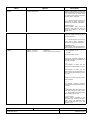
6.3.2.2
HDLC Protocol Information Structure Members
Name
baud_rate
Options
1 200 - 1 Mbit/s (RS-232)
1 200 - 16 Mbit/s (RS-422/485)
Description
Used to specify a single baud
rate for both transmitter and
receiver.
Any values permissible.
Units in bit/s.
The equation to calculate the actual baud rate for FM0/1,
Manchester and Diff. Manchester is as follows :
Actual baud rate = 100 MHz / 16 / ROUND(100 MHz
/ 16 / Desired baud rate)
The equation to calculate the actual baud rate for NRZ/NRZI is as
follows :
Actual baud rate = 100 MHz / ROUND(100 MHz /
Desired baud rate)
Where ROUND() implies that the result is rounded to the nearest
integer.
clock_source
HSS8_CLOCK_DEFAULT
HSS8_CLOCK_BRG1
HSS8_CLOCK_BRG2
HSS8_CLOCK_BRG3
HSS8_CLOCK_BRG4
HSS8_CLOCK_EXT1
HSS8_CLOCK_EXT2
HSS8_CLOCK_EXT3
HSS8_CLOCK_EXT4
HSS8_CLOCK_DEFAULT
connects BRGs [1 - 4] to
Channels [A - D] and
Channels [E - H].
BRGs [1-4].
BRG1 for Channels [A and E]
BRG2 for Channesl [B and F]
BRG3 for Channels [C and G]
BRG4 for Channels [D and H]
External Clocks connected on
CLK_IN Pins.
Note :
HSS8_CLOCK_EXT[1 - 2] can
only
be
used
for
Channels [A and B] and
[E
and
F],
while
HSS8_CLOCK_EXT[3 - 4] can
only
be
used
for
Channels [C and D] and
[G and H].
For NRZ/NRZI :
When transmit clock is set to
HSS8_CLOCK_BRG[1 - 4], then
receive clock is still set to
HSS8_CLOCK_EXT[1 - 4] for
Channels [A - D] and [E - H].
For FM0/1, Manchester and
Diff. Manchester :
Transmit and receive clocks can
be
set
to
one
of
HSS8_CLOCK_BRG[1 - 4] or
HSS8_CLOCK_EXT[1 - 4].
Note :
There are four BRGs and four
clock input pins per
PowerQUICC II processor.
crc_mode
HSS8_HDLC_CRC_MODE_16_BIT
HSS8_HDLC_CRC_MODE_32_BIT
HDLC CRC mode.
diag_mode
HSS8_DIAG_NORMAL
Set diagnostic mode.
Normal operation. Use this for
external loopback.
External loopback RS-422/485 :
Connect TxD+ to RxD+, TxD- to
RxD-, (CLK_OUT+ to CLK_IN+
and CLK_OUT- to CLK_IN- for
synchronous mode).
External loopback - RS-232 :
Connect TxD to RxD, (CLK_OUT
to CLK_IN for synchronous
mode) and RTS to CTS and CD.
Set diagnostic mode.
For synchronous mode :
see encoding_method.
CCII/HSS8/6-MAN/003
CH8MAN03.WPD
2009-08-20
Issue 1.2
Page 21 of 32
Name
Options
HSS8_DIAG_LOOPBACK
Internal loopback :
TxD and RxD are connected
internally. The value on RxD,
CTS and CD is ignored. The
transmitter and receiver share
the same clock source.
HSS8_DIAG_ECHO
The transmitter automatically
resends received data bit-by-bit.
HSS8_DIAG_LOOPBACK_EC
HO
Loopback and echo operation
occur simultaneously.
Description
max_receive_bytes
1 to (2 048 - CRC bytes (2 or 4)) (default) or up to (32 kBytes - CRC
bytes (2 or 4)), depending on how many bytes have been allocated
to the RX and TX buffers (See function hss8Create_device(..)).
Maximum number of bytes to
receive before closing buffer. Set
equal to max_frame_bytes.
max_frame_bytes
1 to 2 048 (default) or up to 32 kBytes, depending on how many
bytes have been allocated to the RX and TX buffers (See function
hss8Create_device(..)).
Maximum number of bytes per
frame. Set equal to the number
of data bytes plus the number of
CRC bytes (either two or four)
per frame.
address_mask
0x0000 - 0xFFFF
HDLC address mask. A one
enables comparison and a zero
masks it.
address1, address2,
address3, address4
0x0000 - 0xFFFF
Four address registers for
address recognition. The SCC
reads the frame address from the
HDLC receiver, compares it
with the address registers, and
masks the result with
address_mask.
For example, to recognize a
frame that begins 0x7E (flag),
0x68, 0xAA, using 16-bit address
recognition, the address registers
should contain 0xAA68 and
address_mask should contain
0xFFFF. For 8-bit addresses,
clear the eight high-order
address bits.
nr_flags_between_frames
0 - 15
M i nimum number of f l a g s
between or before frames.
retransmit_enabled
TRUE
FALSE
Enable re-transmit.
flag_sharing_enabled
TRUE
FALSE
Enable flag sharing.
rx_disabled_during_tx
TRUE
FALSE
Disable receive during transmit.
bus_mode
TRUE
FALSE
Enable bus mode.
bus_mode_rts
TRUE
FALSE
Enable special RTS operation in
HDLC bus mode.
multiple_tx_frames
TRUE
FALSE
Enable multiple
transmit FIFO.
CCII/HSS8/6-MAN/003
CH8MAN03.WPD
2009-08-20
frames
in
Issue 1.2
Page 22 of 32
Name
6.3.2.3
Options
Description
encoding_method
HSS8_HDLC_ENCODING_METHOD_NRZ
HSS8_HDLC_ENCODING_METHOD_NRZI_MARK
HSS8_HDLC_ENCODING_METHOD_NRZI_SPACE
HSS8_HDLC_ENCODING_METHOD_FM0
HSS8_HDLC_ENCODING_METHOD_FM1
HSS8_HDLC_ENCODING_METHOD_MANCHESTER
HSS8_HDLC_ENCODING_METHOD_DIFF_MANCHESTER
RX / TX encoding method. NRZ
and NRZI use no DPLL. FM0/1,
Manchester and Diff_Manchester
use the DPLL for clock
recovery.The clock rate is 16x
when the DPLL is used.
preamble_length
HSS8_DPLL_PREAMBLE_LENGTH_0
HSS8_DPLL_PREAMBLE_LENGTH_8
HSS8_DPLL_PREAMBLE_LENGTH_16
HSS8_DPLL_PREAMBLE_LENGTH_32
HSS8_DPLL_PREAMBLE_LENGTH_48
HSS8_DPLL_PREAMBLE_LENGTH_64
HSS8_DPLL_PREAMBLE_LENGTH_128
Determines the length of the
preamble pattern.
preamble_pattern
HSS8_DPLL_PREAMBLE_PATTERN_00
HSS8_DPLL_PREAMBLE_PATTERN_10
HSS8_DPLL_PREAMBLE_PATTERN_01
HSS8_DPLL_PREAMBLE_PATTERN_11
Determines what bit pattern
precedes each TX frame.
send_idles_or_flags
HSS8_HDLC_SEND_IDLES
HSS8_HDLC_SEND_FLAGS_SYNCS
Send either idles or flags/syncs
between frames as defined by
the protocol. For HDLC the flag
is defined as 0x7E. NRZI
encoding methods may only be
used with flags/syncs.
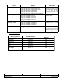
Preamble Requirements
Preamble Pattern
Minimum Preamble Length
Required
NRZI Mark
All zeros
8-bit
NRZI Space
All ones
8-bit
FM0
All ones
8-bit
FM1
All zeros
8-bit
101010...10
8-bit
All ones
8-bit
Decoding Method
Manchester
Differential Manchester
CCII/HSS8/6-MAN/003
CH8MAN03.WPD
2009-08-20
Issue 1.2
Page 23 of 32
6.3.3
BISYNC Mode
This protocol may only be used with the eight SCC ports : Ports A - H.
6.3.3.1
BISYNC Protocol Information Structure
The following structure is defined in the file hss8ControlIfc.h and is given here in abbreviated format
(i.e. reserved and obsolete members are not shown). Always use the structure as defined in hss8ControlIfc.h.
struct hss8BisyncInfoStruct
{
hss8UINT32 baud_rate;
hss8UINT32 clock_source;
hss8UINT32 max_receive_bytes;
hss8UINT32 min_no_sync_pairs;
hss8UINT32 crc_select;
hss8UINT32 receive_bcs;
hss8UINT32 rx_transparant_mode;
hss8UINT32 reverse_data;
hss8UINT32 disable_rx_while_tx;
hss8UINT32 rx_parity;
hss8UINT32 tx_parity;
hss8UINT32 diag_mode;
hss8UINT32 crcc;
hss8UINT32 prcrc;
hss8UINT32 ptcrc;
hss8UINT32 parec;
hss8UINT32 bsync;
hss8UINT32 bdle;
hss8UINT32 cc[8];
hss8UINT32 rccm;
hss8UINT32 sync;
hss8UINT32 syn_length;
hss8UINT32 send_idles_or_flags;
};
typedef struct hss8BisyncInfoStruct hss8BisyncInfo;
CCII/HSS8/6-MAN/003
CH8MAN03.WPD
2009-08-20
Issue 1.2
Page 24 of 32
6.3.3.2
BISYNC Protocol Information Structure Members
Name
baud_rate
Options
Description
1 200 - 1 Mbit/s (RS-232)
1 200 - 16 Mbit/s (RS-422/485)
Used to specify a single baud rate for
both transmitter and receiver.
Any values permissible.
Units in bit/s.
The equation to calculate the actual baud rate for BISYNC is as
follows :
Actual baud rate = 100 MHz / ROUND(100 MHz /
Desired baud rate)
Where ROUND() implies that the result is rounded to the nearest
integer.
clock_source
HSS8_CLOCK_DEFAULT
HSS8_CLOCK_DEFAULT
connects BRGs[1 - 4] to
Channels [A - D] and Channels [E - H].
BRGs [1 - 4].
BRG1 for Channels [A and E]
BRG2 for Channels [B and F]
BRG3 for Channels [C and G]
BRG4 for Channels [D and H]
HSS8_CLOCK_BRG1
HSS8_CLOCK_BRG2
HSS8_CLOCK_BRG3
HSS8_CLOCK_BRG4
HSS8_CLOCK_EXT1
HSS8_CLOCK_EXT2
HSS8_CLOCK_EXT3
HSS8_CLOCK_EXT4
External Clocks connected on
CLK_IN Pins.
When transmit clock is set to
HSS8_CLOCK_BRG[1 - 4], then
receive clock is still set to
HSS8_CLOCK_EXT[1 - 4] for
Channels [A - D] and [E - H].
Note :
There are four BRGs and four clock
input pins per PowerQUICC II
processor.
Note :
HSS8_CLOCK_EXT[1 - 2]
can only be used for
Channels [A and B] and
[E
and
F],
while
HSS8_CLOCK_EXT[3 - 4]
can only be used for
Channels [C and D] and
[G and H].
max_receive_bytes
1 to (2 048 - 2 CRC bytes) (default) or up to (32 kBytes - 2 CRC
bytes), depending on how many bytes have been allocated to the RX
and TX buffers (See function hss8Create_device(..)).
Maximum number of bytes to receive
before closing buffer.
min_no_sync_pairs
0b0000 (0 pairs) - 0b1111 (16 pairs)
Minimum number of SYN1-SYN2 pairs
sent between or before messages. The
entire pair is always sent, regardless of
the syn_length variable.
crc_select
HSS8_BISYNC_CRC_MODE_16
HSS8_BISYNC_CRC_MODE_LRC
CRC selection.
1 : CRC16 (X16 + X15 + X2 + 1) :
Initialise prcrc and ptcrc to all zeros
or all ones.
2 : LRC (sum check) :
For even LRC, initialise prcrc and
ptcrc to zeros, for odd LRC initialise to
ones.
receive_bcs
TRUE
FALSE
Enable Receive
Sequence (BCS).
CCII/HSS8/6-MAN/003
CH8MAN03.WPD
2009-08-20
Block
Check
Issue 1.2
Page 25 of 32
Name
rx_transparant_mode
Options
TRUE
FALSE
Description
Enable Receiver transparent mode.
FALSE :
Normal receiver mode with SYNC
stripping and control character
recognition.
TRUE :
Transparent receiver mode. SYNC’s,
DLE’s and control characters are
recognised only after the leading DLE
character. The receiver calculates the
CRC16 sequence even if it is
programmed to LRC while in
transparent mode. Initialize prcrc to
the CRC16 preset value before setting
rx_transparant_mode.
reverse_data
TRUE
FALSE
Enable Reverse data.
disable_rx_while_tx
TRUE
FALSE
Disable receiver while sending.
rx_parity
tx_parity
HSS8_BISYNC_PARITY_ODD
HSS8_BISYNC_PARITY_LOW
HSS8_BISYNC_PARITY_EVEN
HSS8_BISYNC_PARITY_HIGH
Receive and transmit parity. Parity is
ignored unless crc_select = LRC.
diag_mode
HSS8_DIAG_NORMAL
Normal operation. Use this for
external loopback.
HSS8_DIAG_LOOPBACK
Internal loopback :
TxD and RxD are connected
internally. The value on RxD,
CTS and CD is ignored. The
transmitter and receiver share
the same clock source.
HSS8_DIAG_ECHO
The transmitter automatically
resends received data bit-bybit.
HSS8_DIAG_LOOPBACK_ECHO
Loopback and echo operation
occur simultaneously.
Set diagnostic mode.
External loopback - RS-422/485 :
Connect TxD+ to RxD+, TxD- to RxD-,
CLK_OUT+ to CLK_IN+ and
CLK_OUT- to CLK_IN-.
External loopback - RS-232 :
Connect TxD to RxD, CLK_OUT to
CLK_IN and RTS to CTS and CD.
crcc
0
CRC constant value.
prcrc
ptcrc
0x0000 or
0xFFFF
Preset receiver / transmitter
CRC16/LRC. These values should be
preset to all ones or zeros, depending
on the BCS used.
parec
0 - 65 535
Number of received parity errors.
CCII/HSS8/6-MAN/003
CH8MAN03.WPD
2009-08-20
Issue 1.2
Page 26 of 32
Name
bsync
Options
0bv0000000ssssssss
Description
BISYNC SYNC register. Contains the
value of the SYNC character stripped
from incoming data on receive once
the receiver synchronizes to the data
using the SYN1- SYN2 pair.
vIf v = 1 and the receiver is not in hunt
mode when a SYNC character is
received, this character is discarded.
ssssssss (8 bits) SYNC character. When using 7-bit
characters with parity, the parity bit
should be included in the SYNC
register value.
bdle
0bv0000000dddddddd
BISYNC DLE register. In transparent
mode, the receiver discards any DLE
character received.
vIf v = 1 and the receiver is not in hunt
mode when a DLE character is
received, this character is discarded.
dddddddd (8 bits) DLE character. This character tells the
receiver that the next character is text.
cc[8]
0b0bh-----cccccccc 0b1bh-----cccccccc -
Valid entry.
Entry not valid and is not used.
Control characters 1 to 8.
----- (5 bits) Reserved. Initialise to zero.
bBlock check sequence expected. A
maskable interrupt is generated after
the buffer is closed.
b=0:
The character is written into the
receive buffer and the buffer is closed.
b=1:
The character is written into the
receive buffer. The receiver waits for 1
LRC or 2 CRC bytes and then closes
the buffer.
hEnables hunt mode when the current
buffer is closed.
h=0:
The BISYNC controller maintains
character synchronisation after closing
the buffer.
h=1:
The BISYNC controller enters hunt
mode after closing the buffer. When
b = 1, the controller enters hunt mode
after receiving LRC or CRC.
cccccccc (8 bits) Defines control characters to be
compared to the incoming character.
When using 7-bit characters with
parity, include the parity bit in the
character value.
CCII/HSS8/6-MAN/003
CH8MAN03.WPD
2009-08-20
Issue 1.2
Page 27 of 32
Name
rccm
Options
0b11------00000000 0b11------11111111 -
Ignore these bits when comparing
incoming character.
Enable comparing the incoming
character to cc[n].
Description
Receive control character mask. A one
enables comparison and a zero masks
it.
sync
0xssss (2 bytes)
SYNC character :
Should be programmed with the sync
pattern.
syn_length
HSS8_BISYNC_SYNL_8
HSS8_BISYNC_SYNL_16
HSS8_BISYNC_SYNL_8 :
Should be chosen to implement
mono-sync protocol. The receiver
synchronizes on an 8-bit sync pattern
in sync.
HSS8_BISYNC_SYNL_16 :
The receiver synchronizes on a 16-bit
sync pattern stored in sync.
send_idles_or_flags
CCII/HSS8/6-MAN/003
CH8MAN03.WPD
HSS8_BISYNC_SEND_IDLES
HSS8_BISYNC_SEND_FLAGS_SYNCS
2009-08-20
Send either idles or flags/syncs
between frames as defined by the
protocol. The flag character is equal to
sync.
Issue 1.2
Page 28 of 32
6.3.4
SMC UART Mode
This protocol may only be used with the four SMC ports : Ports I - L.
6.3.4.1
SMC UART Protocol Information Structure
The following structure is defined in the file hss8ControlIfc.h and is given here in abbreviated format
(i.e. reserved and obsolete members are not shown). Always use the structure as defined in hss8ControlIfc.h.
struct hss8SmcUartInfoStruct
{
hss8UINT32 max_receive_bytes;
hss8UINT32 max_idl;
hss8UINT32 data_bits;
hss8UINT32 stop_bits;
hss8UINT32 parity_enable;
hss8UINT32 parity_mode;
hss8UINT32 diag_mode;
hss8UINT32 baud_rate;
};
typedef struct hss8SmcUartInfoStruct hss8SmcUartInfo;
CCII/HSS8/6-MAN/003
CH8MAN03.WPD
2009-08-20
Issue 1.2
Page 29 of 32
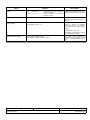
6.3.4.2
SMC UART Protocol Information Structure Members
Name
baud_rate
Options
1 200 - 115.2 kbit/s (RS-232/RS-422/485)
Description
Used to specify a single baud rate for
both transmitter and receiver.
Any values permissible.
Units in bit/s.
The equation to calculate the actual baud rate for the SMC UART is as
follows :
Actual baud rate = 100 MHz / 16 / ROUND(100 MHz / 16
/ Desired baud rate)
Where ROUND() implies that the result is rounded to the nearest integer.
stop_bits
HSS8_UART_STOP_BITS_ONE
HSS8_UART_STOP_BITS_TWO
Number of full stop bits.
data_bits
HSS8_UART_DATA_BITS_5
HSS8_UART_DATA_BITS_6
HSS8_UART_DATA_BITS_7
HSS8_UART_DATA_BITS_8
HSS8_UART_DATA_BITS_9
HSS8_UART_DATA_BITS_10
HSS8_UART_DATA_BITS_11
HSS8_UART_DATA_BITS_12
HSS8_UART_DATA_BITS_13
HSS8_UART_DATA_BITS_14
Number of data bits.
Note :
parity_enable
HSS8_UART_PARITY_NO_PARITY
HSS8_UART_PARITY_ENABLE
Enable or disable parity checking.
parity_mode
HSS8_UART_SMC_PARITY_ODD
HSS8_UART_SMC_PARITY_EVEN
Receive and transmit parity. Parity will
only be checked if parity is enabled.
diag_mode
HSS8_DIAG_NORMAL
HSS8_DIAG_LOOPBACK
Only Channels I - H (i.e. the SMC
channels) support nine or more data bits.
Normal operation. Use this for
external loopback.
Internal loopback :
TxD and RxD are connected
internally. The value on RxD is
ignored.
HSS8_DIAG_ECHO
The transmitter automatically
resends received data bit-by-bit.
HSS8_DIAG_LOOPBACK_ECHO
Loopback and echo operation
occur simultaneously.
Set diagnostic mode.
External loopback - RS-422/485 :
Connect TxD+ to RxD+ and TxD- to
RxD-.
External loopback - RS-232 :
Connect TxD to RxD.
max_receive_bytes
1 to 2 048 (default) or up to 32 kBytes, depending on how many bytes
have been allocated to the RX and TX buffers (See function
hss8Create_device(..)).
Maximum number of bytes that may be
copied into a buffer.
max_idl
0 to 2 048 (default) or up to 32 kBytes, depending on how many bytes
have been allocated to the RX and TX buffers (See function
hss8Create_device(..)).
Maximum idle characters. When a
character is received, the receiver
begins counting idle characters. If
max_idl idle characters are received
before the next data character, an idle
timeout occurs and the buffer is closed.
Thus, max_idl offers a way to demarcate
frames.
To disable the feature, clear max_idl.
The bit length of an idle character is
calculated as follows :
1 + data length (5-14) + 1 (if parity is
used) + number of stop bits (1 - 2). For 8
data bits, no parity, and 1 stop bit, the
character length is 10 bits.
CCII/HSS8/6-MAN/003
CH8MAN03.WPD
2009-08-20
Issue 1.2
Page 30 of 32
7.
Getting Started
After installing the HSS8 Linux Software Driver according to Paragraph 4, test it by following the test procedure
given in hss8Test.txt.
CCII/HSS8/6-MAN/003
CH8MAN03.WPD
2009-08-20
Issue 1.2
Page 31 of 32
8.
Contact Details
8.1
Contact Person
Direct all correspondence and / or support queries to the Project Manager at C²I² Systems.
8.2
Physical Address
C²I² Systems
Unit 3, Rosmead Place, Rosmead Centre
67 Rosmead Avenue
Kenilworth
Cape Town
7708
South Africa
8.3
Postal Address
C²I² Systems
P.O. Box 171
Rondebosch
7701
South Africa
8.4
Voice and Electronic Contacts
Tel
Fax
Email
Email
URL
8.5
:
:
:
:
:
(+27) (0)21 683 5490
(+27) (0)21 683 5435
[email protected]
[email protected]
http://www.ccii.co.za/
Product Support
Support on C²I² Systems products is available telephonically between Monday and Friday from 09:00 to 17:00 CAT.
Central African Time (CAT = GMT + 2).
CCII/HSS8/6-MAN/003
CH8MAN03.WPD
2009-08-20
Issue 1.2
Page 32 of 32