1
User Manual
for the
C 2I2 Systems’
PMC High Speed Serial VxWorks Driver
CCII Document No.
CCII/HSS/6-MAN/002
3.5
Document Issue
Issue Da te
2002-04-11
Print Date
2002-04-11
File Name
P:\HSS\TECH\MAN\USERMAN\cManHssDrv.wpd
© C²I² Syste ms. T he co pyrigh t of this do cum ent is th e prop erty of C ²I² Syste ms. T he do cum ent is iss ued fo r the so le
purpos e for whic h it is supplied , on the ex press term s that it may not be co pied in w hole or pa rt, used by o r disclosed to
others except as authorised in writing by C²I² Systems.
D o c u m en t pr e pa r ed f or C ²I ² S y s te m s
(Pty) Ltd
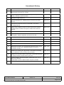
Amen dmen t History
Issue
Description
Date
ECP No
1.0
Initial version created b y splitting cM anSioD rv.wpd, Is sue 1.1 in to
separate SIO and HSS user manuals.
2000-03-16
-
1.1
Upda ted App lication Pro gram In terface (A PI) to corre spond with
version 1 release 0 of the host driver.
2000-05-23
-
2.0
Updated for HSS version 2.0.
2000-06-06
-
2.1
Updated paragraph 4.2, detailing protocol structures and setup
options.
2000-10-31
-
2.3
Updated driver data structures to include DPLL and various
encoding methods.
2001-01-19
-
2.4
Added version display function for driver and firmware software.
Updated UART and HDLC descriptions. Added clock detection
function.
2001-03-19
-
2.5
Added functionality to attach external clocks. Added SMC ports.
2001-04-23
-
2.6
Implemented the BISYNC protocol. Included the BIT functions
descriptions. Added configuration specifics for the X86.
2001-05-21
-
2.6.1
Added HS S Front Panel functionality.
2001-06-15
-
2.6.2
Changed flash programming.
2001-07-05
-
3.0
General up date of driver.
2001-09-13
-
3.1
Updated description of include-files.
2001-09-25
-
3.2
HSS Serial I/O back & front panel boards share the same protocol
information structure now. Updated description of protocol
information structure.
2001-10-01
-
3.3
Added new hssOpen_port_fp() function, which allows for floating
point initialisation of send, receive and clock tasks.
2001-10-12
-
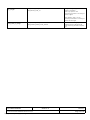
3.4
Added new hssCreate_device_ex() function, which allows the user
to specify th e Rx & Tx buffer s ize for eac h port.
2002-01-17
-
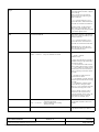
3.5
Updated callback function description: added CRC error and Tx
done e rror reporting .
Updated BIT structure: added oscillator frequency variable.
2002-04-11
-
CCII/HSS/6-MAN/002
P:\HSS\TECH\MAN\USERMAN\cManHssDrv.wpd
Copyright © C²I² Systems (Pty) Ltd, All rights reserved, 2002
2002-04-11
Issue 3.5
Page iii of vi
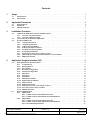
Contents
1
Scope . . . . . . . . . . . . . . . . . . . . . . . . . . . . . . . . . . . . . . . . . . . . . . . . . . . . . . . . . . . . . . . . . . . 1
1.1
1.2
2
Applicable Documents . . . . . . . . . . . . . . . . . . . . . . . . . . . . . . . . . . . . . . . . . . . . . . . . . . . . . 2
2.1
2.2
2.3
3
Specifications . . . . . . . . . . . . . . . . . . . . . . . . . . . . . . . . . . . . . . . . . . . . . . . . . . . . . . . . . . . . . . . . . . . . . . 2
Standards . . . . . . . . . . . . . . . . . . . . . . . . . . . . . . . . . . . . . . . . . . . . . . . . . . . . . . . . . . . . . . . . . . . . . . . . . 2
Other D ocum ents . . . . . . . . . . . . . . . . . . . . . . . . . . . . . . . . . . . . . . . . . . . . . . . . . . . . . . . . . . . . . . . . . . . 2
Installation Procedure . . . . . . . . . . . . . . . . . . . . . . . . . . . . . . . . . . . . . . . . . . . . . . . . . . . . . . 3
3.1
3.2
3.3
4
Identification . . . . . . . . . . . . . . . . . . . . . . . . . . . . . . . . . . . . . . . . . . . . . . . . . . . . . . . . . . . . . . . . . . . . . . . 1
Introduction . . . . . . . . . . . . . . . . . . . . . . . . . . . . . . . . . . . . . . . . . . . . . . . . . . . . . . . . . . . . . . . . . . . . . . . 1
To Build the HSS Driver into the VxWorks Kernel . . . . . . . . . . . . . . . . . . . . . . . . . . . . . . . . . . . . . . . .
3.1.1
Tornado 1.0.1 Environment . . . . . . . . . . . . . . . . . . . . . . . . . . . . . . . . . . . . . . . . . . . . . . . . . . . .
3.1.2
Tornado 2.0 Environment . . . . . . . . . . . . . . . . . . . . . . . . . . . . . . . . . . . . . . . . . . . . . . . . . . . . . .
To Lo ad the D river So ftware Sepa rately . . . . . . . . . . . . . . . . . . . . . . . . . . . . . . . . . . . . . . . . . . . . . . . .
Using the HSS Driver . . . . . . . . . . . . . . . . . . . . . . . . . . . . . . . . . . . . . . . . . . . . . . . . . . . . . . . . . . . . . . . .
3.3.1
Creating the Device . . . . . . . . . . . . . . . . . . . . . . . . . . . . . . . . . . . . . . . . . . . . . . . . . . . . . . . . . . .
3.3.2
Configur ing the Po rts . . . . . . . . . . . . . . . . . . . . . . . . . . . . . . . . . . . . . . . . . . . . . . . . . . . . . . . . .
3.3.3
Adding Re ceive Buffers . . . . . . . . . . . . . . . . . . . . . . . . . . . . . . . . . . . . . . . . . . . . . . . . . . . . . . .
3.3.4
Adding Call-back Functions . . . . . . . . . . . . . . . . . . . . . . . . . . . . . . . . . . . . . . . . . . . . . . . . . . . .
3.3.5
Sending and Rec eiving Data . . . . . . . . . . . . . . . . . . . . . . . . . . . . . . . . . . . . . . . . . . . . . . . . . . .
3.3.6
Destroying the Device . . . . . . . . . . . . . . . . . . . . . . . . . . . . . . . . . . . . . . . . . . . . . . . . . . . . . . . . .
3.3.7
Detecting a n active clock signal on po rts . . . . . . . . . . . . . . . . . . . . . . . . . . . . . . . . . . . . . . . . .
3.3.8
Obtaining the current host and firmware version number . . . . . . . . . . . . . . . . . . . . . . . . . . .
3.3.9
HSS B uilt-In-Tests . . . . . . . . . . . . . . . . . . . . . . . . . . . . . . . . . . . . . . . . . . . . . . . . . . . . . . . . . . . .
3
3
3
3
4
4
4
4
5
6
6
6
7
7
Application Program Interface (API) . . . . . . . . . . . . . . . . . . . . . . . . . . . . . . . . . . . . . . . . . . 8
4.1
4.2
High Speed Serial Driver Interface . . . . . . . . . . . . . . . . . . . . . . . . . . . . . . . . . . . . . . . . . . . . . . . . . . . . . 8
4.1.1
Create Device . . . . . . . . . . . . . . . . . . . . . . . . . . . . . . . . . . . . . . . . . . . . . . . . . . . . . . . . . . . . . . . . 9
4.1.2
Destroy Device . . . . . . . . . . . . . . . . . . . . . . . . . . . . . . . . . . . . . . . . . . . . . . . . . . . . . . . . . . . . . 10
4.1.3
Port Exists? . . . . . . . . . . . . . . . . . . . . . . . . . . . . . . . . . . . . . . . . . . . . . . . . . . . . . . . . . . . . . . . . 11
4.1.4
Set Port Configuration . . . . . . . . . . . . . . . . . . . . . . . . . . . . . . . . . . . . . . . . . . . . . . . . . . . . . . . 12
4.1.5
Get Port Configuration . . . . . . . . . . . . . . . . . . . . . . . . . . . . . . . . . . . . . . . . . . . . . . . . . . . . . . . 13
4.1.6
Open Po rt . . . . . . . . . . . . . . . . . . . . . . . . . . . . . . . . . . . . . . . . . . . . . . . . . . . . . . . . . . . . . . . . . . 14
4.1.7
Close Port . . . . . . . . . . . . . . . . . . . . . . . . . . . . . . . . . . . . . . . . . . . . . . . . . . . . . . . . . . . . . . . . . 16
4.1.8
Send D ata . . . . . . . . . . . . . . . . . . . . . . . . . . . . . . . . . . . . . . . . . . . . . . . . . . . . . . . . . . . . . . . . . . 17
4.1.9
Add Receive Buffer . . . . . . . . . . . . . . . . . . . . . . . . . . . . . . . . . . . . . . . . . . . . . . . . . . . . . . . . . . 18
4.1.10 Remove Receive Buffer . . . . . . . . . . . . . . . . . . . . . . . . . . . . . . . . . . . . . . . . . . . . . . . . . . . . . . 19
4.1.11 Add Call-back . . . . . . . . . . . . . . . . . . . . . . . . . . . . . . . . . . . . . . . . . . . . . . . . . . . . . . . . . . . . . . 20
4.1.12 Remove Call-back . . . . . . . . . . . . . . . . . . . . . . . . . . . . . . . . . . . . . . . . . . . . . . . . . . . . . . . . . . . 21
4.1.13 Detecting a n active clock signal on po rts . . . . . . . . . . . . . . . . . . . . . . . . . . . . . . . . . . . . . . . . 22
4.1.14 Print out current version number . . . . . . . . . . . . . . . . . . . . . . . . . . . . . . . . . . . . . . . . . . . . . . 23
4.1.15 HSS Built-In-Test . . . . . . . . . . . . . . . . . . . . . . . . . . . . . . . . . . . . . . . . . . . . . . . . . . . . . . . . . . . . 24
Driver Data Structures . . . . . . . . . . . . . . . . . . . . . . . . . . . . . . . . . . . . . . . . . . . . . . . . . . . . . . . . . . . . . . 26
4.2.1
UART Mode . . . . . . . . . . . . . . . . . . . . . . . . . . . . . . . . . . . . . . . . . . . . . . . . . . . . . . . . . . . . . . . . 27
4.2.1.1 UART P rotocol Information Struc ture . . . . . . . . . . . . . . . . . . . . . . . . . . . . . . . . . . . . 27
4.2.1.2 UART P rotocol Information Struc ture Memb ers . . . . . . . . . . . . . . . . . . . . . . . . . . . . 28
4.2.2
HDLC Mode . . . . . . . . . . . . . . . . . . . . . . . . . . . . . . . . . . . . . . . . . . . . . . . . . . . . . . . . . . . . . . . . 31
4.2.2.1 HDLC P rotocol Information Struc ture . . . . . . . . . . . . . . . . . . . . . . . . . . . . . . . . . . . . 31
4.2.2.2 HDLC P rotocol Information Struc ture Memb ers . . . . . . . . . . . . . . . . . . . . . . . . . . . . 32
4.2.2.3 Pream ble Requ irements . . . . . . . . . . . . . . . . . . . . . . . . . . . . . . . . . . . . . . . . . . . . . . . 34
CCII/HSS/6-MAN/002
P:\HSS\TECH\MAN\USERMAN\cManHssDrv.wpd
Copyright © C²I² Systems (Pty) Ltd, All rights reserved, 2002
2002-04-11
Issue 3.5
Page iv of vi
4.2.3
4.2.4
5
6
BISYNC Mode . . . . . . . . . . . . . . . . . . . . . . . . . . . . . . . . . . . . . . . . . . . . . . . . . . . . . . . . . . . . . .
4.2.3.1 BISYNC Protocol Information S tructure . . . . . . . . . . . . . . . . . . . . . . . . . . . . . . . . . .
4.2.3.2 BISYNC Protocol Information S tructure Mem bers . . . . . . . . . . . . . . . . . . . . . . . . . .
SMC UART Mode . . . . . . . . . . . . . . . . . . . . . . . . . . . . . . . . . . . . . . . . . . . . . . . . . . . . . . . . . . . .
4.2.4.1 SMC U ART Pro tocol Information Structure . . . . . . . . . . . . . . . . . . . . . . . . . . . . . . . .
4.2.4.2 SMC U ART Pro tocol Information Structure M embers . . . . . . . . . . . . . . . . . . . . . . .
35
35
36
40
40
41
Getting Started . . . . . . . . . . . . . . . . . . . . . . . . . . . . . . . . . . . . . . . . . . . . . . . . . . . . . . . . . . . 43
Contact Details . . . . . . . . . . . . . . . . . . . . . . . . . . . . . . . . . . . . . . . . . . . . . . . . . . . . . . . . . . . 44
6.1
6.2
6.3
6.4
6.5
Contact Person . . . . . . . . . . . . . . . . . . . . . . . . . . . . . . . . . . . . . . . . . . . . . . . . . . . . . . . . . . . . . . . . . . . .
Physical Address . . . . . . . . . . . . . . . . . . . . . . . . . . . . . . . . . . . . . . . . . . . . . . . . . . . . . . . . . . . . . . . . . .
Postal Address . . . . . . . . . . . . . . . . . . . . . . . . . . . . . . . . . . . . . . . . . . . . . . . . . . . . . . . . . . . . . . . . . . . .
Voice an d Electron ic Contac ts . . . . . . . . . . . . . . . . . . . . . . . . . . . . . . . . . . . . . . . . . . . . . . . . . . . . . . .
Product Sup port . . . . . . . . . . . . . . . . . . . . . . . . . . . . . . . . . . . . . . . . . . . . . . . . . . . . . . . . . . . . . . . . . . .
CCII/HSS/6-MAN/002
P:\HSS\TECH\MAN\USERMAN\cManHssDrv.wpd
Copyright © C²I² Systems (Pty) Ltd, All rights reserved, 2002
2002-04-11
44
44
44
44
44
Issue 3.5
Page v of vi
Abbreviations and Acronyms
API
Application Program Interface
BIT
Built-In-Test
BRG
Baudrate Generator
BSD
Berkeley Socket Devices
BSP
Board Support Package
CCII
Communications, Computer Intelligence, Integration
C 2I 2
C²I² Syste ms (Pty ) Ltd
DPLL
Digital Phase-Locked Loop
FTP
File Transfer Protocol
HCC
Host Carrier C ard
HSS
High Spe ed Serial (Acron ym for the C²I² PM C Serial I/O card project)
I/O
Input/Output
PC
Personal Computer
PCI
Peripheral Component Interconnect
PMC
PCI Me zzanine C ard
SBC
Single Board Computer
SCC
Serial Communications Controller
SIO
Serial Input/Output
SMC
Serial Management Controller
TBD
To Be Determined
VME
Versa M odule Euroc ard
CCII/HSS/6-MAN/002
P:\HSS\TECH\MAN\USERMAN\cManHssDrv.wpd
Copyright © C²I² Systems (Pty) Ltd, All rights reserved, 2002
2002-04-11
Issue 3.5
Page vi of vi
1
Scope
1.1
Identification
This document is the User's Manual for the C²I² Systems' Peripheral Component Interconnect (PCI) Mezzanine
Card (PMC) High Speed Serial VxWorks Driver. This document refers to the High Speed Serial VxWorks driver
version 3.5 or later.
1.2
Introduction
The PMC High Speed Serial (HSS) driver is a low level, device-de pendant, interface for transferring data ove r a
C²I² Systems ' HSS PC I Mezzanin e Card (PMC). The driver binaries are provided with explicit installation
instructions .
The driver software distribution consists of (at least) the following files:
ccHss Lib[4|8]vx.y .z.<host>
Host-architecture specific, driver object file:
cc
- CCII Sy stems (Pty) Ltd
HssL ib
- High Speed Serial driver
[4|8]
- 4 port or 8 port HSS PMC
x
- Version num ber
y
- Revision number
z
- Beta number
<host>
- Host for wh ich the binary is built
e.g. “ccHss4v2.4.dmv179” for version 2.4 of the HSS
software, built for a DY4 DMV179 PowerPC host for a 4
port HSS PMC.
ccHss4vx.y.z.firmware.zip containing:
ccHss4vx.y.z -<freq>.hex
HSS firmware.
<freq>
- corresponding oscillator frequency
ccHss Flashvx .y.z.<hos t>
Flash upda te driver.
hssReadme.txt
General information and installation notes.
hssRelease_emb.txt, hssRelease_host.txt
Relea se no tes an d revis ion hist ory: Ple ase ch eck th is file
for information on the latest updates.
ccHs s4vx. y.z.h_ files.zip
Zip file which contains all header files that define the
application progra m interface (AP I) to the driver.
ccHss Test.c, cc HssT est.<ho st>
Samp le C code for ac cessing the H SS driver.
hssChanges.txt
Changes to be made to VxWorks and BS P files.
hssFlash.txt
Procedure for updating the firmware if required.
hssTest.txt
Test procedure for verifying host driver and firmware.
CCII/HSS/6-MAN/002
P:\HSS\TECH\MAN\USERMAN\cManHssDrv.wpd
Copyright © C²I² Systems (Pty) Ltd, All rights reserved, 2002
2002-04-11
Issue 3.5
Page 1 of 45
2
Applicable Docum ents
2.1
Specifications
Not applicable.
2.2
Standards
!
2.3
DI-IPS C-81 443: D ata Item Desc ription fo r a Softw are U ser M anua l.
Other Documents
!
VxWorks 5.3.1, Programmers Guide, Edition 1.
!
MPC860 PowerQUICC™ User’s Manual Rev. 1.
CCII/HSS/6-MAN/002
P:\HSS\TECH\MAN\USERMAN\cManHssDrv.wpd
Copyright © C²I² Systems (Pty) Ltd, All rights reserved, 2002
2002-04-11
Issue 3.5
Page 2 of 45
3
Installation Proc edure
This paragraph describes the installation procedure for the HSS host driver. (The examples given are for a DY4
DMV 179 Po werPC host.)
3.1
To Build the HSS Driver into the VxWorks Kernel
Assume the BSP directory is given as: BSP_DIR = /tornado/target/config/dmv179
3.1.1
Tornado 1.0.1 Environment
!
Copy ccHss4vx.y.z.dmv179 to your $(BSP_DIR)/lib directory as ccHss4.a.
!
Edit the Mak efile in the BSP d irectory
(Use hs sCha nges.txt to copy an d paste th e relevan t informatio n.)
Add the follow ing macro (or e dit the existing one):
EXTR A_M ODU LES = $(BSP _DIR)/lib/c cHss4 .a
! Rebuild all VxWorks images.
3.1.2
Tornado 2.0 Environment
! Copy ccHss4vx.y.z.dmv179 to your $(BSP_DIR)/lib directory as ccHss4.a.
! In the Bu ilds section of the Pro ject Wo rkspace , change the Kern el propertie s to include the ccH ss4.a
library file in the Macros LIBs option.
! Rebuild all VxWorks images.
3.2
To Load the Driver Software Separately
Note this step is not required if the driver was built into the BSP.
If the driver is not built into the BSP, a user can load it separately:
! Copy ccHss4vx.y.z.dmv179 to your present working directory as ccHss4.a.
! From the VxWorks shell type:
ld < ccH ss4.a
CCII/HSS/6-MAN/002
P:\HSS\TECH\MAN\USERMAN\cManHssDrv.wpd
Copyright © C²I² Systems (Pty) Ltd, All rights reserved, 2002
2002-04-11
Issue 3.5
Page 3 of 45
3.3
Using the HSS Driver
3.3.1
Creating the Device
The HSS driver supports multiple HSS PMC on a single host. To establish a connection and construct all the
device s pecific struc tures, a us er mus t create ea ch of the d evices s eparate ly, using the device ID to identify it.
The device ID starts at 0 and increments by 1 for each of the devices. Device 0 refers to the device in the lowest
PMC slot. The HSS driver can not be used until the user has created the device.
Example: For device 0:
/* Create all HSS devices */
hssCreate _device(0);
The device ID is used in all calls to the HSS driver to identify the correct device.
3.3.2
Configuring the Ports
The HSS PMC has four serial communications controllers (SCC’s) [Ports A-D] that support UART and
HDLC/SDLC protoc ols, an d two s erial m anag eme nt con trollers (S MC ’s) [Por ts I&J] th at sup port on ly
asynchronous UART.
After the HSS device has been created, the user must first set the default configuration for each of the ports. To
set the configuration of a port, a protocol-specific information structure is used. Examples of the required structure
is given in c cHssT est.c (for the U ART protocol) a nd can be used as a starting point.
The structures allow the u ser to set all the protocol-s pecific options available on the HSS PMC comm unication
contro ller chip (the MPC860 PowerQUICC™). For available options for each of th e structure fields, see [2 .3.3].
Example: Set two SCC ports to UART mode and two to HDLC mode:
/* Set initial SCC port configuration */
hssSet_p ort_config(0, HS S_PO RT_A, & uart_info);
hssSet_p ort_config(0, HS S_PO RT_B, & uart_info);
hssSet_p ort_config(0, HS S_PO RT_C , &hdlc_info);
hssSet_p ort_config(0, HS S_PO RT_D , &hdlc_info);
/* Set initial SMC port configuration */
hssSet_p ort_config(0, HS S_PO RT_I, &sm c_uart_info);
hssSet_p ort_config(0, HS S_PO RT_J, &s mc_ua rt_info);
3.3.3
Adding Receive Buffers
Note: this step is not necessary anymore. Receive buffers are added automatically by the driver in the
hssOpe n_port() function. It is still possible to call hssAdd_receive_buffer(), but this function will not do anything.
CCII/HSS/6-MAN/002
P:\HSS\TECH\MAN\USERMAN\cManHssDrv.wpd
Copyright © C²I² Systems (Pty) Ltd, All rights reserved, 2002
2002-04-11
Issue 3.5
Page 4 of 45
3.3.4
Adding Call-back Functions
The HSS driver notifies the user of different events by calling a user defined Call-back function. The events for
which the user may specify one or more Call-back functions are:
Send Begin
Send Done
Receive Done
Clock D etect
-
The driver has accepted the data for sending.
The driver has finished sending the data.
Data has be en received a nd written into the use r’s buffer.
A clock s ignal has been de tected on that spec ific port.
Only one Call-back function for each ev ent is recomm ended. For the user to receive data, at least the Receive
Don e Call-b ack m ust be installed . While the Re ceive Done Call-ba ck is ex ecute d, the c orresp ondin g buffe r will
not be accessed by the HS S driver. The user can process the data in the Ca ll-back function or copy the data
somewhere else for processing at the user’s leisure.
Receive function prototype:
void Proces s_rx_data(int dev id, int portid, int crc_error, int userid, int length, void *pdata );
Transmit Begin prototype:
void Proces s_tx_data(int dev id, int portid, int dummy, int use rid, int length, void *pdata);
Transmit Done prototype:
void Proces s_tx_data(int dev id, int portid, int error, int userid, int length, void *pdata);
Clock Detection prototype:
void Proces s_clk_detec t(int devid, int portid, int dummy 1, int userid, int dumm y2, void *dum my3);
devid
portid
crc_error
error
userid
length
pdata
dummy/1/2
dummy3
=
=
=
=
=
=
=
=
=
=
=
device ID.
port ID.
HSS _OK (no CRC e rror).
HSS _ERR OR (CR C error).
HSS _OK (se nd done O K).
HSS _ERR OR (buffer un derrun or CT S lost: send no t complete).
user defined ID.
length of received data.
buffer with received data.
variables not us ed (always 0 ).
variable not use d (always N ULL).
Example: Add a Call-back function for handling receives:
/* Receive function prototype - this function is implemented by the user */
void Proces s_rx_data(int dev id, int portid, int crc_error, int userid, int length, void *pdata );
/* Add receive Call-back */
hssAdd _callback(0, H SS_C B_ON _REC EIVE_D ONE , Process_rx_ data, 0);
CCII/HSS/6-MAN/002
P:\HSS\TECH\MAN\USERMAN\cManHssDrv.wpd
Copyright © C²I² Systems (Pty) Ltd, All rights reserved, 2002
2002-04-11
Issue 3.5
Page 5 of 45
3.3.5
Sending and Receiving Data
To send and receive data on a specified port, the user must first open the port. To sto p send ing or rece iving data
from a p ort, the use r must clo se the po rt.
Example: Send some data on device 0, port B:
/* Open port for sending data */
hssOpe n_port(0, HS S_PO RT_B, 5 0);
/* Send some da ta */
hssSen d_data(0, HS S_PO RT_B, 0 , 256, pbuffer256 , NO_W AIT);
/* Do other stuff */
/*
*/
/* Close port after final usage */
hssClose _port(0, HSS _POR T_B);
3.3.6
Destroying the Device
When the device is no longer required it should be destroyed to free system resources.
Example: Device 0 is no longer required:
/* Close ports after final usage */
hssClose _port(0, HSS _POR T_A);
hssClose _port(0, HSS _POR T_B);
hssClose _port(0, HSS _POR T_C);
hssClose _port(0, HSS _POR T_D);
hssClose _port(0, HSS _POR T_I);
hssClose _port(0, HSS _POR T_J);
/* Destroy device to free resources */
hssDes troy_device(0);
3.3.7
Detecting an active clock signal on ports
To detect when a port’s clock signal becomes active, use the following function.
Example: Detecting a clock signal on device 0 and Port A:
/* Enable port to detect clock */
hssClock_ detect(0, HSS _POR T_A);
A Call-back function gets called once a clock has been detected. After this Call-back function has been serviced,
the user can re-initialise the clock detection routine as shown above.
/* Clock detection prototype - this function is implemented by the user */
void Proces s_clk_even t(int devid, int portid, int dummy 1, int userid, int dumm y2, void *dum my3);
/* adding clock_detect callback */
hssAdd _callback (0,H SS_C B_ON _CLO CK_D ETEC T,Process _clk_detect,0);
Note: The last 2 variables of the clock detection prototype function are dummy variables and are not initialised.
CCII/HSS/6-MAN/002
P:\HSS\TECH\MAN\USERMAN\cManHssDrv.wpd
Copyright © C²I² Systems (Pty) Ltd, All rights reserved, 2002
2002-04-11
Issue 3.5
Page 6 of 45
3.3.8
Obtaining the current host and firmware version number
The following function prints out the current version number of the driver and firmware software:
/* Print current version number */
hssVersion _print(0);
Note: R un hssC reate_d evice(0) first.
3.3.9
HSS Built-In-Tests
The following function displays each port’s statistics: e.g. how many bytes / packets have been accepted / rejected
/ sent / received and how many errors were reported.
Example: Displaying each port’s statistics for device 0:
hssBit_repo rt(0);
To clear the cou nters of the hssB it_report(0) function, use the function hssB it_clear(0).
CCII/HSS/6-MAN/002
P:\HSS\TECH\MAN\USERMAN\cManHssDrv.wpd
Copyright © C²I² Systems (Pty) Ltd, All rights reserved, 2002
2002-04-11
Issue 3.5
Page 7 of 45
4
App lication Prog ram Interfa ce (A PI)
4.1
High Speed Serial Driver Interface
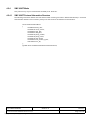
The zip file ccHss4vx.y.z.h_files.zip contains the following header files:
crc.h - used for crc algorithm
hssDe fs.h
hssHo stDriver.h
hssCo ntrolIfc.h
The following files should always be included:
hssDe fs.h
hssHo stDriver.h
hssCo ntrolIfc.h
CCII/HSS/6-MAN/002
P:\HSS\TECH\MAN\USERMAN\cManHssDrv.wpd
Copyright © C²I² Systems (Pty) Ltd, All rights reserved, 2002
2002-04-11
Issue 3.5
Page 8 of 45
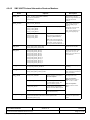
4.1.1
Create Device
Function :
hssCreate_device
Purpose:
Create and initialize the HSS device specific structures.
Arguments:
<dev_id> -
Device ID on the PCI bus. The HSS device in the lowest PCI
slot:<dev_id> = 0, next HSS device: <dev_id> = 1, etc.
Returns:
HSS_OK HSS_ INVALID _PAR AM HSS_PCI_INIT_FAIL HSS_MEM_ALLOC_FAILED HSS_DEVICE_NOT_FOUND HSS_MEM_INVALID_ADDRESS -
On success.
Invalid dev_id supplied.
PCI initialisation failed.
If HSS device structure could not be created in mem ory.
If HSS device <dev_id> was not found on the PCI bus.
If the HSS device PCI address was not valid.
hssStatus h ssCreate_ device(hssD eviceId dev_ id);
Function:
hssCreate_device_ex
Purpose:
Create and initialize the HSS device specific structures. This extended version allow s the use r to
specify the maxim um R x & Tx b uffer size for e ach po rt.
Arguments:
<dev_id> <scc_#_size> <smc_#_size> -
<reserved1&2> -
Device ID on the PCI bus. The HSS device in the lowest PCI
slot:<dev_id> = 0, next HSS device: <dev_id> = 1, etc.
maxim um R x&Tx b uffer size for s pecific scc port.
max imum Rx& Tx bu ffer size for spe cific sm c port. (v alid
arguments: HSS_2K, HSS_4K, HSS_8K, HSS_16K,
HSS_32K)
2 reserved variables for future use.
Returns:
HSS_OK HSS_INVALID_PARAM HSS_PCI_INIT_FAIL HSS_MEM_ALLOC_FAILED HSS_DEVICE_NOT_FOUND HSS_MEM_INVALID_ADDRESS -
On success.
Invalid parameters supplied.
PCI initialisation failed.
If HSS device structure could not be created in mem ory.
If HSS device <dev_id> was not found on the PCI bus.
If the HSS device PCI address was not valid.
hssStatus hssCreate_device_ex(hssDeviceId dev_id, unsigned int scc_0_size, unsigned int scc_1_size,
unsigne d int scc_2 _size, un signed in t scc_3_ size,
unsigned int smc_0_size, unsigned int smc_1_size,
unsigned int rese rved1, unsigne d int reserved2);
Notes:
One of these two func tions has to be called (once pe r device) b efore any other func tion call to the
specified device will be valid. The function h ssCrea te_dev ice() sets up the Rx & Tx bu ffer size for all
ports to the default value of 2Kbytes.
CCII/HSS/6-MAN/002
P:\HSS\TECH\MAN\USERMAN\cManHssDrv.wpd
Copyright © C²I² Systems (Pty) Ltd, All rights reserved, 2002
2002-04-11
Issue 3.5
Page 9 of 45
4.1.2
Destroy Device
Function:
hssDestroy_device
Purpose:
Destroy the HSS device specific structures.
Arguments:
<dev_id> -
Device ID on the PCI bus. The HSS device in the lowest PCI
slot: <dev_id> = 0, next HSS device: <dev_id> = 1, etc.
Returns:
HSS_OK HSS_INVALID_PARAM HSS_PCI_INIT_FAIL HSS_ERROR -
On success.
Invalid dev_id supplied.
PCI initialisation failed
If the interrupt tasks have not been destroyed.
hssStatus h ssDestroy_ device(hssD eviceId dev_ id);
Notes:
After this function is called, no other function call to the specified device will be valid, except for
hssCreate _device(..).
CCII/HSS/6-MAN/002
P:\HSS\TECH\MAN\USERMAN\cManHssDrv.wpd
Copyright © C²I² Systems (Pty) Ltd, All rights reserved, 2002
2002-04-11
Issue 3.5
Page 10 of 45
4.1.3
Port Exists?
Function:
hssPo rt_exists
Purpose:
Determine whether a port exists on the specified device.
Arguments:
<dev_id> <port_id> -
Device ID on the PCI bus. The HSS device in the lowest PCI
slot: <dev_id> = 0, next HSS device: <dev_id> = 1, etc.
Port to query.
Returns:
TRUE FALSE -
If the port exists in hardware.
If the port does not exist in hardware.
hssBoo l hssPort_exists(h ssDeviceId dev_id, hssP ortId port_id);
CCII/HSS/6-MAN/002
P:\HSS\TECH\MAN\USERMAN\cManHssDrv.wpd
Copyright © C²I² Systems (Pty) Ltd, All rights reserved, 2002
2002-04-11
Issue 3.5
Page 11 of 45
4.1.4
Set Port Configuration
Function:
hssS et_por t_config
Purpose:
Set port protocol and protocol configuration.
Arguments:
<dev_id> -
Device ID on the PCI bus. The HSS device in the lowest PCI
slot: <dev_id> = 0, next HSS device: <dev_id> = 1, etc.
Port to configure.
Pointer to information struct used for configuration.
<port_id> <p_info> Returns:
HSS_OK HSS_PCI_INIT_FAIL HSS_ ERRO R HSS_INVALID_PARAM HSS_PORT_NOT_INSTALLED HSS_ DEVIC E_BU SY HSS_ DEVIC E_NO T_RES PON DING -
HSS_INCORRECT_PARAM_COMBINATION -
On success.
PCI initialisation failed.
If the Tx/Rx tasks have not been destroyed.
Invalid dev_id or port_id supplied.
If the port does nor exists.
If no PCI buffer is available.
If the HSS control block could not be accessed
within a certain time.
If an incorrect parameter combination was selected
in the protocol structure.
hssStatus h ssSet_po rt_config(hssD eviceId dev_ id, hssPortId port_id, hs sProtocolInfo* p_ info);
Notes:
The <p_in fo> po inter m ust po int to a va lid hssP rotoco lInfo stru cture w ith all protocol information set
as required. If only a few items need to change, the hssGet_port_config(..) function should be used
to fill in the rest of the structure.
Warning:
Do not call this function while sending or receiving data as this may result in data loss.
CCII/HSS/6-MAN/002
P:\HSS\TECH\MAN\USERMAN\cManHssDrv.wpd
Copyright © C²I² Systems (Pty) Ltd, All rights reserved, 2002
2002-04-11
Issue 3.5
Page 12 of 45
4.1.5
Get Port Configuration
Function:
hssG et_por t_config
Purpose:
Get port protocol and protocol configuration.
Arguments:
<dev_id> -
Device ID on the PCI bus. The HSS device in the lowest PCI
slot: <dev_id> = 0, next HSS device: <dev_id> = 1, etc.
Port to get configuration info from.
Pointer to information struct used for configuration.
<port_id> <p_info> Returns:
HSS_OK HSS_ERROR HSS_INVALID_PARAM HSS_DEVICE_BUSY HSS_DEVICE_NOT_RESPONDING -
On success.
If the Tx/Rx tasks have not been destroyed.
Invalid dev_id or port_id supplied.
If no PCI buffer is available.
If the HSS control block could not be accessed within a
certain time.
hssStatus h ssGet_po rt_config(hssD eviceId dev_ id, hssPortId port_id, hs sProtocolInfo* p_ info);
Notes:
The <p_info> pointer must point to an existing hssProtocolInfo structure.
CCII/HSS/6-MAN/002
P:\HSS\TECH\MAN\USERMAN\cManHssDrv.wpd
Copyright © C²I² Systems (Pty) Ltd, All rights reserved, 2002
2002-04-11
Issue 3.5
Page 13 of 45
4.1.6
Open Port
Function:
hssOpen _port
Purpose:
Open specified port for send and receive.
Arguments:
<dev_id> -
Device ID on the PCI bus. The HSS device in the lowest PCI
slot: <dev_id> = 0, next HSS device: <dev_id> = 1, etc.
Port to open for send and receive.
Priority of the send, receive and clock detection task
servicing this port.
<port_id> <priority> -
Returns:
HSS_OK HSS_ERROR HSS_INVALID_PARAM HSS_PORT_NOT_INSTALLED HSS_PORT_NOT_CONFIGURED HSS_DEVICE_BUSY HSS_DEVICE_NOT_RESPONDING HSS_MEM_ALLOC_FAILED -
On success.
If opening of port failed.
Invalid dev_id or port_id supplied
If the port does nor exists.
If an ‘Open’ is attempted on a port before configuring the
port.
If no PCI buffer is available.
If the HSS control block could not be accessed within a
certain time.
If failed to create semaphore or spawn receive task.
hssStatus h ssOpen _port(hssDe viceId dev_id, hs sPortId port_id, hss INT32 priority);
CCII/HSS/6-MAN/002
P:\HSS\TECH\MAN\USERMAN\cManHssDrv.wpd
Copyright © C²I² Systems (Pty) Ltd, All rights reserved, 2002
2002-04-11
Issue 3.5
Page 14 of 45
Function:
hssOp en_port_ fp
Purpose:
Open specified port for send and receive with floating point functionality.
Arguments:
<dev_id> -
Device ID on the PCI bus. The HSS device in the lowest PCI
slot: <dev_id> = 0, next HSS device: <dev_id> = 1, etc.
Port to open for send and receive.
Priority of the send, receive and clock detection task
servicing this port.
Floating point enable for send, receive and clock detect task:
HSS_TX_TASK_FP_ENABLE,
HSS_RX_TASK_FP_ENABLE,
HSS_CLK_TASK_FP _ENABLE
<port_id> <priority> <fp_options> -
Returns:
HSS_OK HSS_ERROR HSS_INVALID_PARAM HSS_PORT_NOT_INSTALLED HSS_PORT_NOT_CONFIGURED HSS_DEVICE_BUSY HSS_DEVICE_NOT_RESPONDING HSS_MEM_ALLOC_FAILED -
On success.
If opening of port failed.
Invalid dev_id or port_id supplied.
If the port does nor exists.
If an ‘Open’ is attempted on a port before configuring the
port.
If no PCI buffer is available.
If the HSS control block could not be accessed within a
certain time.
If failed to create semaphore or spawn receive task.
hssStatus h ssOpen _port_fp(hssD eviceId dev_ id, hssPortId port_id, hs sINT32 priority, char fp_ options);
Notes:
These functions must be called prior to attempting to send or receive on any channel of the specified
port.
Opening a port spawns a receive, send and clo ck det ect tas k for tha t spec ific port. Th e priority of thes e task s is
specified by <priority>.
CCII/HSS/6-MAN/002
P:\HSS\TECH\MAN\USERMAN\cManHssDrv.wpd
Copyright © C²I² Systems (Pty) Ltd, All rights reserved, 2002
2002-04-11
Issue 3.5
Page 15 of 45
4.1.7
Close Port
Function:
hssClose_p ort
Purpose:
Close specified port for send and receive.
Arguments:
<dev_id> -
Device ID on the PCI bus. The HSS device in the lowest PCI
slot: <dev_id> = 0, next HSS device: <dev_id> = 1, etc.
Port to close for send and receive.
<port_id> Returns:
HSS_OK HSS_ERROR HSS_INVALID_PARAM HSS_PORT_NOT_INSTALLED HSS_PORT_NOT_CONFIGURED HSS_DEVICE_BUSY HSS_DEVICE_NOT_RESPONDING -
On success.
If opening of port failed or Rx/Tx tasks have not been
destroye d..
Invalid dev_id or port_id supplied.
If the port does nor exists.
If an ‘Open’ is attempted on a port before configuring the
port.
If no PCI buffer is available.
If the HSS control block could not be accessed within a
certain time.
hssStatus h ssClose_ port(hssDev iceId dev_id, hss PortId port_id);
Notes:
Closing a port a secon d time has no effect a nd still re turns H SS_ OK, s ince th e port w as suc cessf ully
closed.
CCII/HSS/6-MAN/002
P:\HSS\TECH\MAN\USERMAN\cManHssDrv.wpd
Copyright © C²I² Systems (Pty) Ltd, All rights reserved, 2002
2002-04-11
Issue 3.5
Page 16 of 45
4.1.8
Send Data
Function:
hssSen d_data
Purpose:
Send data o ver the specifie d cha nnel.
Arguments:
<dev_id> -
Device ID on the PCI bus. The HSS device in the lowest PCI
slot: <dev_id> = 0, next HSS device: <dev_id> = 1, etc.
Port on w hich data must be sent.
Channel on which data must be sent. If a port has only one
channel, <chan_id> = 0.
Number of bytes to send.
Pointer to buffer with at least <nr_bytes> bytes of data.
Not used anymore.
<port_id> <chan_id> <nr_bytes><p_data> <timeout> Returns:
HSS_OK HSS_INVALID_PARAM HSS_PORT_NOT_INSTALLED HSS_PORT_NOT_OPEN HSS_DEVICE_BUSY HSS_DEVICE_NOT_RESPONDING -
On success.
Invalid dev_id or port_id supplied.
If the port does nor exists.
If the port is no t open ye t.
If no PCI buffer is available.
If the HSS control block could not be accessed within a
certain time.
hssStatus hssSend_data(hssDeviceId dev_id, hssPortId port_id, hssChannelId chan_id, hssCount nr_bytes,
hssBufferP tr p_data, hssInt32 tim eout);
Notes:
The po rt must be opene d before a ttempting to send d ata over it.
CCII/HSS/6-MAN/002
P:\HSS\TECH\MAN\USERMAN\cManHssDrv.wpd
Copyright © C²I² Systems (Pty) Ltd, All rights reserved, 2002
2002-04-11
Issue 3.5
Page 17 of 45
4.1.9
Add Receive Buffer
Function:
hssAdd_receive_buffer
Purpose:
Add a receiv e buffe r to a sp ecified chan nel.
Arguments :
<dev_id> <port_id> <chan_id> <min_nr_bytes> <max_nr_bytes> <p_data> -
Device ID on the PCI bus. The HSS device in the lowest PCI
slot: <dev_id> = 0, next HSS device: <dev_id> = 1, etc.
Port on which data must be received.
Cha nnel o n whic h data mus t be rec eived . If a port h as on ly
one channel, <chan_id> = 0.
Minimum number of bytes to receive before Call-back
function is called.
Maximu m num ber of bytes to receive into this buffer.
Pointer to buffer with space for at least <max_nr_bytes>
bytes of data.
Returns:
HSS_OK -
On success.
hssStatus hssAdd_receive_buffer(hssDeviceId dev_id, hssPortId port_id, hssChannelId chan_id, hssCount
min_nr_b ytes, hssCou nt max_n r_bytes, hssB ufferPtr p_data);
Note:
This function is not used anymore . The receive bu ffers are added internally. The user may still call
this function, but this function returns only HSS_OK.
CCII/HSS/6-MAN/002
P:\HSS\TECH\MAN\USERMAN\cManHssDrv.wpd
Copyright © C²I² Systems (Pty) Ltd, All rights reserved, 2002
2002-04-11
Issue 3.5
Page 18 of 45
4.1.10
Remove Receive Buffer
Function:
hssRemove_receive_buffer
Purpose:
Rem ove a receiv e buffe r from a specifie d cha nnel.
Arguments:
<dev_id> <port_id> <chan_id> <p_data> Returns:
HSS_OK -
Device ID on the PCI bus. The HSS device in the lowest PCI
slot: <dev_id> = 0, next HSS device: <dev_id> = 1, etc.
Port on which data must be received.
Cha nnel o n whic h data mus t be rec eived . If a port h as on ly
one channel, <chan_id> = 0.
Pointer to buffer to be removed.
On success.
hssStatus hssRem ove_re ceive_b uffer(hssD eviceId dev_id, hssPo rtId port_id, hssChanne lId chan_id, hssBufferPtr
p_data);
Note:
This function is not used anym ore. Th e rece ive bu ffers are remo ved in ternally . The u ser m ay still ca ll
this function, but this function returns only HSS_OK.
CCII/HSS/6-MAN/002
P:\HSS\TECH\MAN\USERMAN\cManHssDrv.wpd
Copyright © C²I² Systems (Pty) Ltd, All rights reserved, 2002
2002-04-11
Issue 3.5
Page 19 of 45
4.1.11
Add Call-back
Function:
hssAdd_callback
Purpose:
Add a user defined Call-back routine.
Arguments:
<dev_id> -
Device ID on the PCI bus. The HSS device in the lowest PCI
slot: <dev_id> = 0, next HSS device: <dev_id> = 1, etc.
Call-back type, one of: HSS_CB_ON_SEND_BEGIN,
HSS_CB_ON_SEND_DONE,
HSS_CB_ON_RECEIVE_DONE,
HSS_CB_ON_CLOCK_DETECT
User function.
User identifier. This identifier will be passed to the Call-back
function when it is called.
<cb_type> -
<Call-back> <user_id> -
Returns:
HSS_OK HSS_INVALID_PARAM HSS_MEM_ALLOC_FAILED -
On success.
Invalid dev_id supplied.
If HSS Ca ll-back node co uld not be created in memo ry
hssSta tus hssAdd_ callback (hssDe viceId de v_id, hss Callbac kType c b_type, h ssCallb ack Ca ll-back, hss UserId
user_id);
Notes:
Four call-backs are provided for us er notification from the driver:
HSS_CB_ON_SEND_BEGIN:
This Call-back will be called as soon as the data has been handed over to the driver for sending.
HSS_CB_ON_SEND_DONE:
This Call-back will be called whe n all the data for a given s end has be en sent by the d river.
HSS_CB_ON_RECEIVE_DONE:
This Call-back will be called when a block of data has been received by the driver. The user must
add at least one of these call-backs to receive data.
Only one call-back for each above type per device is recommended. The call-back function receives the port id,
such that the user can distinguish which port triggered the call-back. More than one call-back function may be
used, in which case the call-backs will be called in the sequence they were added.
HSS_CB_ON_CLOCK_DETECT:
This C all-bac k will be called w hen a clock s ignal h as be en de tected on a po rt. The u ser m ust ad d only
one of the se call-ba cks. This Call-bac k function will only be c alled onc e a port ha s been instructed to
detect a clock sign al, e.g. calling the function hssC lock_detect().
Note:
HSS_CB_ON_RECEIVE_BEGIN:
This Call-back does not exist anymore.
CCII/HSS/6-MAN/002
P:\HSS\TECH\MAN\USERMAN\cManHssDrv.wpd
Copyright © C²I² Systems (Pty) Ltd, All rights reserved, 2002
2002-04-11
Issue 3.5
Page 20 of 45
4.1.12
Remove Call-back
Function:
hssRemove_callback
Purpose:
Remove a user defined Call-back routine.
Arguments:
<dev_id> <cb_type> -
<Call-back><user_id> -
Device ID on the PCI bus. The HSS device in the lowest PCI
slot: <dev_id> = 0, next HSS device: <dev_id> = 1, etc.
Call-back type, one of: HSS_CB_ON_SEND_BEGIN,
HSS_CB_ON_SEND_DONE,HSS_CB_ON_RECEIVE_DON
E, HSS_CB_ON_CLOCK_DETECT
User function to remove.
User identifier. This identifier must be the same as the one
passed to hssAdd_callback.
Returns:
HSS_OK HSS_INVALID_PARAM -
On success.
Invalid dev_id supplied.
hssStatus hssRemov e_callba ck(hssD eviceId dev_id, hssCallbackType cb_type, hssCallback Call-back, hssUse rId
user_id);
CCII/HSS/6-MAN/002
P:\HSS\TECH\MAN\USERMAN\cManHssDrv.wpd
Copyright © C²I² Systems (Pty) Ltd, All rights reserved, 2002
2002-04-11
Issue 3.5
Page 21 of 45
4.1.13
Detecting an active clock signal on ports
Function:
hssClock_detect
Purpose:
Set up a port to detect when clock signal becomes active.
Arguments:
<dev_id> -
Device ID on the PCI bus. The HSS device in the lowest PCI
slot: <dev_id> = 0, next HSS device: <dev_id> = 1, etc.
Port o n whic h to de tect clo ck sign al.
<port_id> Returns:
HSS_OK HSS_INVALID_PARAM HSS_PORT_NOT_INSTALLED HSS_DEVICE_BUSY HSS_DEVICE_NOT_RESPONDING -
On success.
Invalid dev_id or port_id supplied.
If the port does nor exists.
If no PCI buffer is available.
If the HSS control block could not be accessed within a
certain time.
hssStatus h ssClock_d etect(hssDe viceId dev_id, hs sPortId port_id);
CCII/HSS/6-MAN/002
P:\HSS\TECH\MAN\USERMAN\cManHssDrv.wpd
Copyright © C²I² Systems (Pty) Ltd, All rights reserved, 2002
2002-04-11
Issue 3.5
Page 22 of 45
4.1.14
Print out current version number
Function:
hssVersion_print
Purpose:
To obtain the current version number of the driver and firmware software.
Arguments:
<dev_id> -
Device ID on the PCI bus. The HSS device in the lowest PCI
slot: <dev_id> = 0, next HSS device: <dev_id> = 1, etc.
Returns:
HSS_OK HSS_INVALID_PARAM HSS_DEVICE_BUSY HSS_DEVICE_NOT_RESPONDING -
On success.
Invalid dev_id supplied.
If no PCI buffer is available.
If the HSS control block could not be accessed within a
certain time.
hssStatus h ssVersion_ print(hssDevice Id dev_id);
Note:
Run first hssC reate_device (dev_id);
CCII/HSS/6-MAN/002
P:\HSS\TECH\MAN\USERMAN\cManHssDrv.wpd
Copyright © C²I² Systems (Pty) Ltd, All rights reserved, 2002
2002-04-11
Issue 3.5
Page 23 of 45
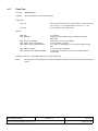
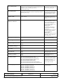
4.1.15
HSS Built-In-Test
The follow ing structu res define the HS S Built_In _Test va riables (de fined in hss Contro lIfc.h):
BIT structures:
struct hssBoardBitInfoStruct
{
hssUINT 32 board_n umber;
hssUINT32 board_type;
hssUINT32 firmware_version;
hssUINT32 firmware_revision;
hssUINT32 firmware_beta;
hssUINT32 oscillator_freq;
char firmw are_cre ation_da te[30];
};
typedef struct hssBoardBitInfoStruct hssBoardBitInfo;
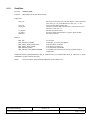
struct hssSendBitInfoStruct
{
hssCount nr_accepted;
hssCount nr_rejected;
hssCount nr_errors;
hssCo unt nr_se nt;
hssCount nr_bytes_accepted;
hssCount nr_bytes_rejected;
hssCo unt nr_by tes_sen t;
};
typedef struct hssSendBitInfoStruct hssSendBitInfo;
struct hssReceiveBitInfoStruct
{
hssCount nr_buffers_busy;
hssCount nr_received;
hssCount nr_bytes_received;
hssCount nr_errors;
};
typedef struct hssReceiveBitInfoStruct hssReceiveBitInfo;
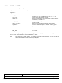
Main BIT structure:
struct hssBitInfoStruct
{
hssBo ardBitInfo board_ bit;
hssSe ndBitInfo tx_scc_ bit[HSS _HW _NR _SCC ];
hssRe ceiveB itInfo rx_scc _bit[HS S_HW _NR _SCC ];
hssSe ndBitInfo tx_smc _bit[HS S_HW _NR _SM C];
hssRe ceiveB itInfo rx_sm c_bit[HS S_HW _NR _SM C];
};
typedef struct hssBitInfoStruct hssBitInfo;
CCII/HSS/6-MAN/002
P:\HSS\TECH\MAN\USERMAN\cManHssDrv.wpd
Copyright © C²I² Systems (Pty) Ltd, All rights reserved, 2002
2002-04-11
Issue 3.5
Page 24 of 45
Three functions give access to the HSS Built_In_Test structures:
Function:
hssBit_getstruct
Purpose:
To obtain the latest BIT variables.
Arguments:
<dev_id> -
Device ID on the PCI bus. The HSS device in the lowest PCI
slot: <dev_id> = 0, next HSS device: <dev_id> = 1, etc.
Pointer to BIT info stru ct.
<bit_info> Returns:
HSS_OK HSS_INVALID_PARAM HSS_DEVICE_BUSY HSS_DEVICE_NOT_RESPONDING -
On success.
Invalid dev_id supplied.
If no PCI buffer is available.
If the HSS control block could not be accessed within a
certain time.
hssStatus h ssBit_getstruct(hs sDeviceId d ev_id, hssBitInfo *b it_info);
Function:
hssBit_report
Purpose:
To display each port’s statistics.
Arguments:
<dev_id> -
Device ID on the PCI bus. The HSS device in the lowest PCI
slot: <dev_id> = 0, next HSS device: <dev_id> = 1, etc.
Returns:
HSS_OK HSS_INVALID_PARAM HSS_DEVICE_BUSY HSS_DEVICE_NOT_RESPONDING -
On success.
Invalid dev_id supplied.
If no PCI buffer is available.
If the HSS control block could not be accessed within a
certain time.
hssStatus h ssBit_report(hss DeviceId de v_id);
Function:
hssBit_clear
Purpose:
To clear each port’s counters.
Arguments:
<dev_id> -
Device ID on the PCI bus. The HSS device in the lowest PCI
slot: <dev_id> = 0, next HSS device: <dev_id> = 1, etc.
Returns:
HSS_OK HSS_INVALID_PARAM HSS_DEVICE_BUSY HSS_DEVICE_NOT_RESPONDING -
On success.
Invalid dev_id supplied.
If no PCI buffer is available.
If the HSS control block could not be accessed within a
certain time.
hssStatus h ssBit_clear(hss DeviceId de v_id);
CCII/HSS/6-MAN/002
P:\HSS\TECH\MAN\USERMAN\cManHssDrv.wpd
Copyright © C²I² Systems (Pty) Ltd, All rights reserved, 2002
2002-04-11
Issue 3.5
Page 25 of 45
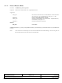
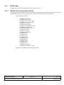
4.2
Driver Data Structures
Each protocol defines a protocol information structure used to configure a port with protoc ol spe cific optio ns. Th is
paragraph details the information structures used by each protocol and explains the use and limitations of every
structure mem ber.
hssProtocolInfo structure:
struct hssProtocolInfoStruct
{
hssUINT32 protocol_id;
/* only used for HSS Front Pane l boards - value ignored otherwise */
hssUINT32 elec_interface;
union
{
/* SCC info */
hssUa rtInfo uart;
hssHdlcInfo hdlc;
hssBisyncInfo bisync;
/* SMC info */
hssSm cUartInfo smc_ uart;
} info;
};
typedef struct hssProtocolInfoStruct hssProtocolInfo;
______________________________________________________________
protocol_id:
HSS_PROTOCOL_UART
HSS_PROTO COL_HDLC
HSS_PROTOCOL_BISYNC
HSS_PROTOCOL_SMC_UART
elec_interface: (only used for HSS Front Panel boards)
HSS_RS485
/* RS485/422 */
HSS_RS232_INT_CTL_LINES
/* RS232 : control lines (RTS , CTS, CD ) are
connected internally */
HSS_RS232_EXT_CTL_LINES
/* RS232: control lines (RTS, CTS, CD) need to be
connected externally */
CCII/HSS/6-MAN/002
P:\HSS\TECH\MAN\USERMAN\cManHssDrv.wpd
Copyright © C²I² Systems (Pty) Ltd, All rights reserved, 2002
2002-04-11
Issue 3.5
Page 26 of 45
4.2.1
UART Mode
This protocol may only be used with the four SCC ports: Ports A-D.
4.2.1.1
UART Protocol Information Structure
The followin g struc ture is d efined in the file hssControlIfc.h and is given here in abbreviated format (i.e. reserved
and obsolete members are not shown). Always use the structure as defined in hssControlIfc.h.
struct hssUartInfoStruct
{
hssUIN T32 ba ud_rate ;
hssUINT32 clock_source;
hssU INT3 2 flow_ contro l;
hssUINT32 stop_bits;
hssUINT32 data_bits;
hssUINT32 uart_mode;
hssUINT32 freeze_tx;
hssUINT32 rx_zero_stop_bits;
hssUINT32 sync_mode;
hssUINT32 disable_rx_while_tx;
hssUINT32 parity_enable;
hssUINT32 rx_p arity;
hssUINT32 tx_pa rity;
hssUINT32 diag_mode;
hssUINT32 max_receive_bytes;
hssU INT3 2 ma x_idl;
hssUINT 32 brkcr;
hssUINT32 parec;
hssUINT32 frmec;
hssUINT32 nosec;
hssUINT32 brkec;
hssUINT32 uaddr1;
hssUINT32 uaddr2;
hssUINT32 toseq;
hssUIN T32 cc [8];
hssUINT32 rccm;
};
typedef struct hssUartInfoStruct hssUartInfo;
CCII/HSS/6-MAN/002
P:\HSS\TECH\MAN\USERMAN\cManHssDrv.wpd
Copyright © C²I² Systems (Pty) Ltd, All rights reserved, 2002
2002-04-11
Issue 3.5
Page 27 of 45
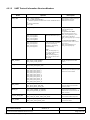
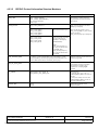
4.2.1.2
UART Protocol Information Structure Members
Nam e
Options
Description
baud_ rate
1200 - 115kbps (RS232)
1200 - 2.4Mbps (RS422/RS485)
0 - Indicates separate transmitter and receiver baudrates will be
set.
Any values permissible.
Units in bps.
This mem ber is used to spe cify a
single b audra te for bo th
transm itter and receive r.
clock_source
HSS_CLOCK_DE FAULT
HSS_CLOCK_DE FAULT
connects BRG[1-4] to
Port[A -D].
For s y n c hr o n o us U A R T:
when transm it clock is set to
HSS_CLOCK_BR G[1-4], then
receive clock is still set to
H S S _ C L O C K _ E X T [1 - 4 ] f o r P o r t[ A D].
For a s y n ch r o n ou s U A R T:
transmit & receive clocks can be
set to one of
HSS_CLOCK_BR G[1-4] or
HSS _CLO CK_ EXT [1-4].
H S S _ C L O C K _B R G 1
H S S _ C L O C K _B R G 2
H S S _ C L O C K _B R G 3
H S S _ C L O C K _B R G 4
Baud rate Ge nerato rs [1-4].
HSS_CLOCK_EXT1
HSS_CLOCK_EXT2
HSS_CLOCK_EXT3
HSS_CLOCK_EXT4
External Clocks connected
on Pins: RXCLK[1-4]
(RS232) or CLKIN[1-4]
(RS48 5/RS4 22).
Note:
HSS_CLOCK_EXT[1-2]
c a n o nl y be u s e d f o r S C C
Port[A&B], while
HSS_CLOCK_EXT[3-4]
c a n o nl y be u s e d f o r S C C
Port[C &D].
flow_control
HSS_UART_FLOW_NORMAL
H S S _ U A R T _ FL O W _ A S Y N C
Normal or asynchronous flow
contro l.
stop_b its
H S S _ U A R T _ ST O P _ B IT S _ O N E
H S S _U A R T_ S TO P _B IT S _T W O
Number of full stop bits.
data_b its
HSS_UART_DATA_B ITS_5
HSS_UART_DATA_B ITS_6
HSS_UART_DATA_B ITS_7
HSS_UART_DATA_B ITS_8
HSS_UART_DATA_B ITS_9
HSS_UART_DATA_B ITS_10
HSS_UART_DATA_B ITS_11
HSS_UART_DATA_B ITS_12
HSS_UART_DATA_B ITS_13
HSS_UART_DATA_B ITS_14
Num ber of d ata bits. N ote on ly
ports I & J (i.e. the SMC ports) can
select 9 or more data bits.
uart_mode
HSS_UART_MODE_NORMAL
H S S _ UA R T _ MO D E _ M AN _ M M
H S S _ UA R T _ MO D E _ AU T O _ M M
Selec t UAR T mo de: no rmal,
man ual m ultidrop o r autom atic
multidrop mode.
freeze_ tx
H S S _ U A R T _ F R E E Z E _ T X _N O R M A L
HSS_UART_FREEZE_TX_FREEZE
Paus e (freez e) trans missio n.
Transmission continues when set
back to norm al.
rx_zero _stop_ bits
H S S _ U A R T _ R X _ Z E R O _ S T O P _B I T S _ N O R M A L
H S S _ U A R T _ RX _ Z E R O _ S TO P _ B I TS _ N O N E
If set to none, the receiver
receives data without stop bits.
sync_mode
H S S _ U A R T _ SY N C _ M O D E _ A S YN C
H S S _ U A R T _ SY N C _ M O D E _ S YN C
Select asynchronous (normal) or
synchronous mode.
CCII/HSS/6-MAN/002
P:\HSS\TECH\MAN\USERMAN\cManHssDrv.wpd
Copyright © C²I² Systems (Pty) Ltd, All rights reserved, 2002
2002-04-11
Issue 3.5
Page 28 of 45
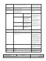
disable_ rx_wh ile_tx
H S S _ U A R T _ D I S A B LE _ R X _ W H I L E _ T X _N O R M A L
HSS_UART_DISABLE_RX _WHILE_TX_DISABLE
Enab le (norm al) or disa ble
receiver while transmitting. Used
in multidrop mode to prevent
reception of own messages.
parity_ enab le
HSS_UART_PARITY_NO_PARITY
HSS_UART_PARITY_ENAB LE
Enable or disable parity checking.
rx_parity, tx_ parity
H S S _ U A R T _ PA R I T Y _O D D
H S S _ U A R T _ PA R I T Y _L O W
H S S _ U A R T _ P A R I TY _ E V E N
H S S _ U A R T _ PA R I T Y _H I G H
Rece ive and transm it parity.
Parity w ill only be c heck ed if par ity
is enabled.
diag_mode
HSS_DIAG_NORMAL
Norm al ope ration. U se this
for external loopback.
H S S _ D I AG _ L O O P B A C K
Internal loopback: T X D &
RXD are connected
internally. The value on
RXD , CTS & CD is
ignored. The transmitter
and receiver share the
same clock source.
H S S _ D I AG _ E C H O
The transmitter
automatically resends
receive d data bit-by-bit.
H S S _ D I AG _ L O O P B A C K _E C H O
Loopback and echo
operation occur
simultaneous ly.
Set diagnostic mode.
External loopback - RS485:
conn ect TX D+ to R XD+ , TXD - to
RXD-, (TXCLK+ to RXCLK+ and
TXCLK- to RXCLK- for
synchro nous m ode).
External loopback - RS232:
conn ect TX D to R XD, (T XCL K to
RXCLK for synchronous mode)
a n d R T S to C T S & C D .
For HSS Front Panel I/O Board:
p r og r am elec_interface=
H S S _ R S 2 3 2 _ IN T _ C T L _ L IN E S
and connect TXD to RXD, (TXCLK
to RXC LK for syn chronou s mod e).
I g n or e R T S , C T L & C D .
max_receive_bytes
1 to 2048 (default) or up to 32 Kbytes, depending on how many
bytes have been allocated to the Rx & Tx buffers (See function
hssCre ate_dev ice_ex()).
Maximum number of bytes that
may be copied into a buffer.
max_idl
0 to 2048 (default) or up to 32 Kbytes, depending on how many
bytes have been allocated to the Rx & Tx buffers (See function
hssCre ate_dev ice_ex()).
Maximum idle characters. When a
character is received, the receiver
begin s cou nting idle chara cters. If
max_ idl idle charac ters are
receive d befo re the n ext data
characte r, an idle time out occu rs
and the buffer is closed. Thus,
max _idl offers a way to dem arcate
frames. To disable the feature,
clear max_idl. The bit length of an
idle character is calculated as
follows: 1 + data length (5-9) + 1
(if parity is used) + number of stop
bits (1-2). For 8 data bits, no
parity, and 1 stop bit, the character
length is 10 bits.
brkcr
0 - 2048
Number of break characters sent
by transmitter. For 8 data bits, no
parity, 1 s top bit, an d 1 sta rt bit,
each break character consists of
10 zero bits.
parec
0 - 65535
Number of received parity errors.
frmec
0 - 65535
Num ber of rece ived cha racters
with framing errors.
CCII/HSS/6-MAN/002
P:\HSS\TECH\MAN\USERMAN\cManHssDrv.wpd
Copyright © C²I² Systems (Pty) Ltd, All rights reserved, 2002
2002-04-11
Issue 3.5
Page 29 of 45
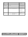
nosec
0 - 65535
Num ber of rece ived cha racters
with noise errors.
brkec
0 - 65535
Number of break conditions on the
signa l.
uaddr1, uad dr2
0x0000 - 0x00FF
Addre ss in m ultidrop m ode. O nly
the lower 8 bits are used so the
upper 8 bits should be cleared.
toseq
0x0000 - 0x00FF
Transmit out of sequence
characte r (e.g. XON , XOFF ).
cc[8]
0b00------ccc ccccc
0b10------cccccccc
- va lid entry
- entry not valid and is not used.
Control character 1 to 8. These
chara cters ca n be u sed to delimit
received messages.
------ (6 bits) - re serve d.
Initialise to zero.
cccccccc (8 bits) - defines control
characters to be compared to the
incomin g charac ter.
rccm
0b11------00000000
0b11------11111111
CCII/HSS/6-MAN/002
P:\HSS\TECH\MAN\USERMAN\cManHssDrv.wpd
Copyright © C²I² Systems (Pty) Ltd, All rights reserved, 2002
- ignore these bits when comparing
incomming character
- enable comparing the incoming
characte r to cc[n].
2002-04-11
Rece ive con trol char acter m ask.
A one enables comparison and a
zero m asks it.
Issue 3.5
Page 30 of 45
4.2.2
HDLC Mode
This protocol may only be used with the four SCC ports: Ports A-D.
4.2.2.1
HDLC Protocol Information Structure
The followin g struc ture is d efined in the file hssControlIfc.h and is given here in abbreviated format (i.e. reserved
and obsolete members are not shown). Always use the structure as defined in hssControlIfc.h.
struct hssHdlcInfoStruct
{
hssUINT32 tx_baud_rate;
hssUINT32 rx_baud_rate;
hssUINT32 clock_source;
hssUINT32 crc_mode;
hssUINT32 diag_mode;
hssUINT32 max_receive_bytes;
hssUINT32 max_frame_bytes;
hssUINT32 address_mask;
hssUINT32 address1;
hssUINT32 address2;
hssUINT32 address3;
hssUINT32 address4;
hssUINT32 nr_flags_between_frames;
hssUINT32 retransmit_enabled;
hssUINT32 flag_sharing_enabled;
hssUINT32 rx_disabled_during_tx;
hssUINT32 bus_mode;
hssUINT32 bus_mode_rts;
hssUINT32 multiple_tx_frames;
hssUINT32 encoding_method;
hssUINT32 preamble_length;
hssUINT32 preamble_pattern;
hssUINT32 send_idles_or_flags;
};
typedef struct hssHdlcInfoStruct hssHdlcInfo;
CCII/HSS/6-MAN/002
P:\HSS\TECH\MAN\USERMAN\cManHssDrv.wpd
Copyright © C²I² Systems (Pty) Ltd, All rights reserved, 2002
2002-04-11
Issue 3.5
Page 31 of 45
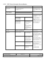
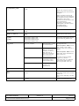
4.2.2.2
HDLC Protocol Information Structure Members
Name
tx_baud_rate,
rx_bau d_rate
Options
Description
NB: It is n ot pos sible to s pecify
the transmitter and receiver
baudrate separately anymore.
S e t b o th v ar ia b le s to t he s am e
baudrate.
1200 - 115kbps (RS232)
1200 - 12Mbps (RS422/RS485)
Any values permissible.
Units in bps.
OBSOLETE VARIABLES
tx_clock_direction
rx_clock_direction
clock_source
HSS_CLOCK_DE FAULT
H S S _ C L O C K _B R G 1
H S S _ C L O C K _B R G 2
H S S _ C L O C K _B R G 3
H S S _ C L O C K _B R G 4
Baud rate Ge nerato rs [1-4].
HSS_CLOCK_EXT1
HSS_CLOCK_EXT2
HSS_CLOCK_EXT3
HSS_CLOCK_EXT4
External Clocks connected
on Pins: RXCLK[1-4]
(RS232) or CLKIN[1-4]
(RS48 5/RS4 22).
HSS_CLOCK_DE FAULT
conn ects B RG[1 -4] to Po rt[A-D].
For NRZ/NRZI: when transm it
clock is set to
HSS_CLOCK_BR G[1-4], then
receive clock is still set to
HSS_CLOCK_EXT[1-4] for
Port[A -D].
For FM0/1 , Manc hester & Diff.
Manchester: transmit & receive
clocks can be set to one of
HSS _CLO CK_B RG[1-4 ] or
HSS _CLO CK_ EXT [1-4].
Note:
HSS_CLOCK_EXT[1-2]
c a n o nl y be u s e d f o r S C C
Port[A&B], while
HSS_CLOCK_EXT[3-4]
c a n o nl y be u s e d f o r S C C
Port[C &D].
crc_mode
HSS _HD LC_C RC_ MO DE_ 16_B IT
HSS _HD LC_C RC_ MO DE_ 32_B IT
diag_mode
HSS_DIAG_NORMAL
H S S _ D I AG _ L O O P B A C K
HDLC CRC m ode.
Norm al ope ration. U se this
for external loopback.
Internal loopback: T X D &
RXD are connected
internally. The value on
RXD , CTS & CD is
ignored. The transmitter
and receiver share the
same clock source.
H S S _ D I AG _ E C H O
The transmitter
automatically resends
receive d data bit-by-bit.
H S S _ D I AG _ L O O P B A C K _E C H O
Loopback and echo
operation occur
simultaneous ly.
CCII/HSS/6-MAN/002
P:\HSS\TECH\MAN\USERMAN\cManHssDrv.wpd
Copyright © C²I² Systems (Pty) Ltd, All rights reserved, 2002
2002-04-11
Set diagnostic mode.
External loopback - RS485:
conn ect TX D+ to R XD+ , TXD - to
RXD-, (TXCLK+ to RXCLK+ and
TXCLK- to RXCLK- for
synchro nous m ode).
External loopback - RS232:
conn ect TX D to R XD, (T XCL K to
RXCLK for synchronous mode)
a n d R T S to C T S & C D .
For HSS Front Panel I/O Board:
p r og r am elec_interface=
H S S _ R S 2 3 2 _ IN T _ C T L _ L IN E S
a n d c on n e c t T X D t o R X D ,
(TXCLK to RXCLK for
s y n c h ro n o u s m o d e) . Ig n o r e R T S ,
CTL & CD.
For synchronous mode:
see encoding_method.
Issue 3.5
Page 32 of 45
max_receive_bytes
1 to (2048 - CRC bytes (2 or 4)) (default) or up to (32 Kbytes CRC bytes (2 or 4)), depending on how many bytes have been
allocated to the Rx & Tx buffers (See function
hssCre ate_dev ice_ex()).
Max imum num ber of b ytes to
receive before closing buffer. Set
equal to max_frame_bytes.
max_frame_bytes
1 to 2048 (default) or up to 32 Kbytes, depending on how many
bytes have been allocated to the Rx & Tx buffers (See function
hssCre ate_dev ice_ex()).
Maximum number of bytes per
frame. Set equal to the number
of data bytes plus the number of
CRC bytes (either 2 or 4) per
frame.
address_mask
0x0000 - 0xFFFF
HDLC address mask. A one
enables comp arison an d a zero
mas ks it.
address1, address2,
address3, address4
0x0000 - 0xFFFF
Four address registers for
a d d re s s re c o g ni ti o n . T h e S C C
reads the frame address from the
HDL C rece iver, com pares it
with the address registers, and
mas ks the re sult with
addre ss_m ask.
For example, to recognize a
frame tha t begins 0 x7E (flag),
0x68, 0xAA,
using 16-bit address recognition,
the ad dress register s sho uld
contain 0xAA68 and
address_mask
shou ld conta in 0xFF FF. Fo r 8-bit
addresses, clear the eight highorder address bits.
nr_flags_between_frames
0 - 15
Minimum number of flags
between or before frames.
retransmit_enabled
TRUE
FALSE
Enab le re-tran smit.
flag_sharing_enabled
TRUE
FALSE
Enable flag sharing.
rx_disab led_du ring_tx
TRUE
FALSE
Disab le rece ive dur ing tran smit.
bus_mode
TRUE
FALSE
Enable bus mode.
bus_m ode_rts
TRUE
FALSE
Enab le spec ial RTS opera tion in
HDLC bus mode.
multiple_tx_frames
TRUE
FALSE
Enab le mu ltiple fram es in
t r an s m i t F I F O .
encoding_method
HSS_UART_ENCODING_METHOD_NRZ
H S S _ U A R T _ E N C O D I N G _ M E T H O D _ N R ZI _ M A R K
H S S _ U A R T _ EN C O D I N G _ M E TH O D _ N R Z I_ S P A C E
H S S _ UA R T _ EN C O D IN G _ M E TH O D _ FM 0
H S S _ UA R T _ EN C O D IN G _ M E TH O D _ FM 1
HSS_UART_ENCODING_METHOD_MANCHESTER
H S S _ U A R T _ E N C O D I N G _ M E T H O D _ D IF F _ M A N C H E S T E R
R x / Tx e n c od i n g m e t h od . N R Z
and NRZI use no DPLL. FM0/1,
Manchester & Diff_Manchester
use the DPLL for clock
recovery.The clock rate is 16x
when the DPLL is used.
pream ble_leng th
HSS_DPLL_PREAM BLE_LENGTH_0
HSS_DPLL_PREAM BLE_LENGTH_8
HSS_DPLL_PREAM BLE_LENGTH_16
HSS_DPLL_PREAM BLE_LENGTH_32
HSS_DPLL_PREAM BLE_LENGTH_48
HSS_DPLL_PREAM BLE_LENGTH_64
HSS_DPLL_PREAM BLE_LENGTH_128
Determines the length of the
preamble pattern.
CCII/HSS/6-MAN/002
P:\HSS\TECH\MAN\USERMAN\cManHssDrv.wpd
Copyright © C²I² Systems (Pty) Ltd, All rights reserved, 2002
2002-04-11
Issue 3.5
Page 33 of 45
preamble _pattern
HSS_DPLL_PREAM BLE_PATTERN_00
HSS_DPLL_PREAM BLE_PATTERN_10
HSS_DPLL_PREAM BLE_PATTERN_01
HSS_DPLL_PREAM BLE_PATTERN_11
Determ ines wh at bit pattern
precedes each Tx frame.
send_idles_or_flags
H S S _ H D L C _ S E N D _ ID L E S
H S S _ H D L C _ SE N D _ F L A G S _S Y N C S
Send either idles or flags/syncs
between frames as defined by
the protocol. For HDLC the flag
is defined as 0x7E. NRZI
encoding methods may only be
used with flags/syncs.
4.2.2.3
Preamble Requirements
Decoding Method
Preamb le Pattern
Minimu m Prea mble Le ngth
Required
NRZI M ark
All zeros
8-bit
NRZI Space
All ones
8-bit
FM0
All ones
8-bit
FM1
All zeros
8-bit
101010...10
8-bit
All ones
8-bit
Manchester
Differential Manchester
CCII/HSS/6-MAN/002
P:\HSS\TECH\MAN\USERMAN\cManHssDrv.wpd
Copyright © C²I² Systems (Pty) Ltd, All rights reserved, 2002
2002-04-11
Issue 3.5
Page 34 of 45
4.2.3
BISYNC Mode
This protocol may only be used with the four SCC ports: Ports A-D.
4.2.3.1
BISYNC Protocol Information Structure
The followin g struc ture is d efined in the file hssControlIfc.h and is given here in abbreviated format (i.e. reserved
and obsolete members are not shown). Always use the structure as defined in hssControlIfc.h.
struct hssBisyncInfoStruct
{
hssUIN T32 ba ud_rate ;
hssUINT32 clock_source;
hssUINT32 max_receive_bytes;
hssUINT32 min_no_sync_pairs;
hssUIN T32 crc _select;
hssUINT32 receive_bcs;
hssUINT32 rx_transparant_mode;
hssUINT32 reverse_data;
hssUINT32 disable_rx_while_tx;
hssUINT32 rx_p arity;
hssUINT32 tx_pa rity;
hssUINT32 diag_mode;
hssUINT32 crcc;
hssUINT32 prcrc;
hssUINT32 ptcrc;
hssUINT32 parec;
hssUINT32 bsync;
hssUINT32 bdle;
hssUIN T32 cc [8];
hssUINT32 rccm;
hssUINT32 sync;
hssUINT32 syn_length;
hssUINT32 send_idles_or_flags;
};
typedef struct hssBisyncInfoStruct hssBisyncInfo;
CCII/HSS/6-MAN/002
P:\HSS\TECH\MAN\USERMAN\cManHssDrv.wpd
Copyright © C²I² Systems (Pty) Ltd, All rights reserved, 2002
2002-04-11
Issue 3.5
Page 35 of 45
4.2.3.2
BISYNC Protocol Information Structure Members
Name
Options
Description
baud_ rate
1200 - 115kbps (RS232)
1200 - 12Mbps (RS422/RS485)
Any values permissible.
Units in bps.
This mem ber is used to spe cify a
single baudrate for both transmitter
and re ceiver.
clock_source
HSS_CLOCK_DE FAULT
HSS _CLO CK_ DEF AUL T con nects
BRG [1-4] to P ort[A-D ].
H S S _ C L O C K _B R G 1
H S S _ C L O C K _B R G 2
H S S _ C L O C K _B R G 3
H S S _ C L O C K _B R G 4
Baud rate Ge nerato rs [1-4].
HSS_CLOCK_EXT1
HSS_CLOCK_EXT2
HSS_CLOCK_EXT3
HSS_CLOCK_EXT4
External Clocks connected
on Pins: RXCLK[1-4]
(RS232) or CLKIN[1-4]
(RS48 5/RS4 22).
Whe n the tra nsm it clock is set to
HSS_CLOC K_BRG[1-4], then receive
clock is still set to
HSS _CLO CK_ EXT [1-4] for P ort[A-D ].
Note:
HSS_CLOCK_EXT[1-2]
c a n o nl y be u s e d f o r S C C
Port[A&B], while
HSS_CLOCK_EXT[3-4]
c a n o nl y be u s e d f o r S C C
Port[C &D].
max_receive_bytes
1 t o (2 0 4 8 - 2 C R C b y te s ) (d e f au l t) o r u p t o ( 3 2 K by t es - 2 C RC
bytes), depending on how many bytes have been allocated to the
Rx & T x buffers (S ee function hssCre ate_dev ice_ex()).
Maximum num ber of bytes to receive
before clos ing buffer.
min_no_ sync_pairs
0b0000 (0 pairs) - 0b1111 (16 pairs)
Minim um nu mber o f SYN1 -SYN2 pairs
sent between or before messages.
The e ntire pa ir is alwa ys sen t,
regardless of the syn_len gth
variable.
crc_select
HSS_BISYNC_CRC_M ODE_16
H S S _ B I SY N C _ C R C _ M O D E _L R C
CRC selection.
1: CRC 16 (X16 + X15 + X2 + 1):
initialise prcrc & ptcrc to all zeros or
all ones.
2 : L R C ( s u m ch e c k ): fo r e ve n L R C ,
initialise prcrc & ptcrc to zeros, for
odd LRC initialise to ones.
receive_bcs
TRUE
FALSE
Enable Receive Block Check
Sequ ence (BCS ).
CCII/HSS/6-MAN/002
P:\HSS\TECH\MAN\USERMAN\cManHssDrv.wpd
Copyright © C²I² Systems (Pty) Ltd, All rights reserved, 2002
2002-04-11
Issue 3.5
Page 36 of 45
rx_transparant_mode
TRUE
FALSE
Enab le Rec eiver tra nspa rent m ode.
FALS E: norm al rece iver m ode w ith
SYNC stripping and control character
recognition.
TRUE: transparent receiver mode.
SYNC ’s, DLE’s a nd con trol characte rs
are recognised only after the leading
DLE character. The receiver
calculates the CRC16 sequence even
if it is progra mm ed to
LRC while in transparent mode.
Initialize prcrc to the CRC16 preset
value before setting
rx_transparant_mode.
reverse _data
TRUE
FALSE
Enable Reverse data.
disable_ rx_wh ile_tx
TRUE
FALSE
Disable receiver while sending.
rx_parity
tx_parity
H S S _ B I SY N C _ P A R IT Y _ O D D
H S S _ B I SY N C _ P A R IT Y _ L O W
H S S _ B I S Y N C _ P A R IT Y _ E V E N
H S S _ B I SY N C _ P A R IT Y _ H IG H
Rece ive and transm it parity. Pa rity is
ignored unless crc_select = L R C .
diag_mode
HSS_DIAG_NORMAL
Norm al ope ration. U se this
for external loopback.
H S S _ D I AG _ L O O P B A C K
Internal loopback: T X D &
RXD are connected
internally. The value on
RXD , CTS & CD is
ignored. The transmitter
and receiver share the
same clock source.
H S S _ D I AG _ E C H O
The transmitter
automatically resends
receive d data bit-by-bit.
H S S _ D I AG _ L O O P B A C K _E C H O
Loopback and echo
operation occur
simultaneous ly.
Set diagnostic mode.
External loopback - RS485: connect
TXD+ to RXD +, TXD - to RXD -,
TXC LK+ to RXC LK+ a nd TX CLK - to
RXC LK-.
External loopback - RS232: connect
TXD to RXD, TXCLK to RXCLK and
RTS to CTS & CD.
For HSS Front Panel I/O Board:
p r og r am elec_interface=
H S S _ R S 2 3 2 _ IN T _ C T L _ L IN E S and
conn ect TX D to R XD, T XCL K to
R X C L K . Ig n o re R T S , C T L & C D .
crcc
0
CRC constant value.
prcrc
ptcrc
0x0000 or
0xFFFF
Preset receiver / transmitter
CRC16/LRC. These values should be
prese t to all
o n e s or z e ro s , de p e n di n g on t h e B C S
used.
parec
0 - 65535
Number of received parity errors.
CCII/HSS/6-MAN/002
P:\HSS\TECH\MAN\USERMAN\cManHssDrv.wpd
Copyright © C²I² Systems (Pty) Ltd, All rights reserved, 2002
2002-04-11
Issue 3.5
Page 37 of 45
bsync
0bv0000000ssssssss
BISYNC SYNC register. Contains the
value of the SYNC character stripped
from incoming
data on receive once the receiver
synchronizes to the data using the
SYN1 - SYN2 pair.
v - if v = 1a nd the receive r is not in
hunt m ode w hen a SYN C cha racter is
received, this character is discarded.
ssssss ss (8 bits) - SY NC ch aracter.
Whe n using 7-bit cha racters with
parity, the parity bit should be included
in the SYNC register value.
bdle
0bv0000000dddddddd
BISYNC DLE register. In transparent
mode, the receiver discards any DLE
character received.
v - if v = 1a nd the receive r is not in
hunt m ode w hen a DLE chara cter is
received, this character is discarded.
ddddd ddd (8 bits) - D LE cha racter.
This character tells the receiver that
the ne xt chara cter is tex t.
cc[8]
0b0bh -----ccccccc c
0b1bh-----cccccccc
- valid entry
- entry not valid and is not used.
Control character 1 to 8.
----- (5 bits) - re serve d.
Initialise to zero.
b - Bloc h che ck seq uenc e expe cted. A
maskable interrupt is generated after
the buffer is closed.
b = 0: the character is written into the
receive buffer and the buffer is closed.
b = 1: the character is written into the
receive b uffer. The rec eiver waits fo r 1
LRC or 2 CRC bytes and then closes
the buffer.
h - Enables hunt mode when the
current buffer is closed.
h = 0: the BISYNC controller maintains
character synchronisation after closing
the buffer.
h = 1: the B ISYNC controller en ters
hunt m ode after c losing the b uffer.
When b = 1, the controller enters hunt
m o d e a ft e r r e c ei v in g L R C o r C R C .
cccccccc (8 bits) - defines control
characters to be compared to the
incom ing cha racter. W hen u sing 7- bit
characters with parity, include the
parity bit in the character value.
rccm
0b11------00000000
0b11------11111111
sync
- ignore these bits when comparing
incomming character
- enable comparing the incoming
characte r to cc[n].
0xssss (2 bytes)
CCII/HSS/6-MAN/002
P:\HSS\TECH\MAN\USERMAN\cManHssDrv.wpd
Copyright © C²I² Systems (Pty) Ltd, All rights reserved, 2002
Rece ive con trol char acter m ask. A
one en ables co mpariso n and a zero
mas ks it.
SYNC character: should be
programmed with the sync pattern.
2002-04-11
Issue 3.5
Page 38 of 45
syn_len gth
HSS_BISYNC_SYNL_8
HSS_BISYNC_SYNL_16
HSS_BISYNC_SYNL_8: should be
chosen to implement
mono-sync protocol. The
receiver synchronizes on an 8-bit sync
pattern in sync.
HSS_BISYNC_SYNL_16: The
receiver synchronizes on a 16-bit sync
pattern stored in sync.
send_idles_or_flags
H S S _ B I S Y N C _ S E N D _I D L E S
H S S _ B I SY N C _ S E N D _ FL A G S _ S Y N C S
CCII/HSS/6-MAN/002
P:\HSS\TECH\MAN\USERMAN\cManHssDrv.wpd
Copyright © C²I² Systems (Pty) Ltd, All rights reserved, 2002
2002-04-11
Send either idles or flags/syncs
between frames as defined by the
protoc ol.The flag cha racter is e qual to
sync.
Issue 3.5
Page 39 of 45
4.2.4
SMC UART Mode
This protocol may only be used with the two SMC ports: Ports I&J.
4.2.4.1
SMC UART Protocol Information Structure
The followin g struc ture is d efined in the file hssControlIfc.h and is given here in abbreviated format (i.e. reserved
and obsolete members are not shown). Always use the structure as defined in hssControlIfc.h.
struct hssSmcUartInfoStruct
{
hssUIN T32 ba ud_rate ;
hssUINT32 clock_source;
hssUINT32 stop_bits;
hssUINT32 data_bits;
hssUINT32 parity_enable;
hssUINT32 parity_mode;
hssUINT32 diag_mode;
hssUINT32 max_receive_bytes;
hssU INT3 2 ma x_idl;
};
typedef struct hssSmcUartInfoStruct hssSmcUartInfo;
CCII/HSS/6-MAN/002
P:\HSS\TECH\MAN\USERMAN\cManHssDrv.wpd
Copyright © C²I² Systems (Pty) Ltd, All rights reserved, 2002
2002-04-11
Issue 3.5
Page 40 of 45
4.2.4.2
SMC UART Protocol Information Structure Members
Na m e
Options
Description
baud_ rate
1200 - 115kbps (RS232/RS422/RS485)
Any values permissible.
Units in bps.
This m emb er is use d to
specify a single baudrate for
both transmitter and
receive r.
clock_source
HSS_CLOCK_DE FAULT
HSS_CLOCK_DE FAULT
connects BRG[1-2] to
Port[I-J].
Transmit & receive clocks
can be set to one of
HSS_CLOCK_BR G[1-4] or
HSS _CLO CK_ EXT [1-4].
H S S _ C L O C K _B R G 1
H S S _ C L O C K _B R G 2
H S S _ C L O C K _B R G 3
H S S _ C L O C K _B R G 4
Baud rate Ge nerato rs [1-4].
HSS_CLOCK_EXT1
HSS_CLOCK_EXT2
HSS_CLOCK_EXT3
HSS_CLOCK_EXT4
External Clocks connected on
Pins: RXCLK[1-4] (RS232) or
CLKIN [1-4] (RS4 85/RS 422).
Note: HSS_CLOCK_EXT[1-2]
can o nly be u sed fo r SMC Port I,
while HSS_CLOCK_EXT[3-4]
can only be used for SMC Port J.
stop_b its
H S S _ U A R T _ ST O P _ B IT S _ O N E
H S S _U A R T_ S TO P _B IT S _T W O
Number of full stop bits.
data_b its
HSS_UART_DATA_B ITS_5
HSS_UART_DATA_B ITS_6
HSS_UART_DATA_B ITS_7
HSS_UART_DATA_B ITS_8
HSS_UART_DATA_B ITS_9
HSS_UART_DATA_B ITS_10
HSS_UART_DATA_B ITS_11
HSS_UART_DATA_B ITS_12
HSS_UART_DATA_B ITS_13
HSS_UART_DATA_B ITS_14
Num ber of d ata bits. N ote
only ports I & J (i.e. the
SMC ports) can select 9 or
more data bits.
parity_ enab le
HSS_UART_PARITY_NO_PARITY
HSS_UART_PARITY_ENAB LE
Enab le or disa ble pa rity
checking.
parity_mode
H S S _ U A R T _ SM C _ P A R I TY _ O D D
H S S _ U A R T _ S M C _ P A R I TY _ E V E N
Rece ive and transm it parity.
Parity w ill only be c heck ed if
parity is enabled.
diag_mode
HSS_DIAG_NORMAL
Normal operation. Use this for
external loopback.
H S S _ D I AG _ L O O P B A C K
max_receive_bytes
Internal loopback: T X D & R X D
are connected internally. The
value on RXD is ignored.
H S S _ D I AG _ E C H O
The tra nsm itter autom atically
resen ds rec eived data b it-by-bit.
H S S _ D I AG _ L O O P B A C K _E C H O
Loopback and echo operation
occur simultane ously.
1 to 2048 (default) or up to 32 Kbytes, depending on how many bytes
have been allocated to the Rx & Tx buffers (See function
hssCre ate_dev ice_ex()).
CCII/HSS/6-MAN/002
P:\HSS\TECH\MAN\USERMAN\cManHssDrv.wpd
Copyright © C²I² Systems (Pty) Ltd, All rights reserved, 2002
2002-04-11
Set diagnostic mode.
External loopback RS485: conn ect TX D+ to
RXD + & TX D- to RX D-.
External loopback RS232: conn ect TX D to
RXD.
Maximum number of bytes
that may be copied into a
buffer.
Issue 3.5
Page 41 of 45
max_idl
0 to 2048 (default) or up to 32 Kbytes, depending on how many bytes
have been allocated to the Rx & Tx buffers (See function
hssCre ate_dev ice_ex()).
CCII/HSS/6-MAN/002
P:\HSS\TECH\MAN\USERMAN\cManHssDrv.wpd
Copyright © C²I² Systems (Pty) Ltd, All rights reserved, 2002
2002-04-11
Maximum idle characters.
Whe n a ch aracte r is
received, the receiver
begin s cou nting idle
chara cters. If m ax_idl id le
characters are received
before the ne xt data
character, an idle timeout
occu rs and the bu ffer is
closed. T hus, m ax_idl offers
a way to demarcate frames.
To disable the feature, clear
max_idl. The bit length of an
idle character is calculated
as follow s: 1 + d ata len gth
(5-14) + 1 (if parity is used)
+ num ber of stop bits (1-2).
For 8 data bits, no pa rity,
and 1 stop bit, the character
length is 10 bits.
Issue 3.5
Page 42 of 45
5
Getting Started
After installing the host driver according to paragraph 3.1, test the host driver following the test procedure given
in hssTe st.txt.
CCII/HSS/6-MAN/002
P:\HSS\TECH\MAN\USERMAN\cManHssDrv.wpd
Copyright © C²I² Systems (Pty) Ltd, All rights reserved, 2002
2002-04-11
Issue 3.5
Page 43 of 45
6
Con tact D etails
6.1
Contact Person
Direct all correspondence and / or support queries to the Project Manager (HSS) at C2I2 Systems.
6.2
Physical Address
C2I2 S ystems (Pty) Ltd
Unit 3, 67 Rosmead Avenue
Kenilw orth
Cape Town
7701
South Africa
6.3
Postal Address
C2I2 S ystems (Pty) Ltd
P.O. Box 171
Rondebosch
Cape Town
7701
South Africa
6.4
Voice and Electronic Contacts
Tel:
Fax:
Ema il:
Ema il:
URL:
6.5
(+27) 21 683 5490
(+27) 21 683 5435
[email protected]
[email protected]
http://www.ccii.co.za/
Product Support
Support on C2I2 Systems’ products is available telephonically between Monday and Friday from 09:00 to 17:00
CAT. C entral African Tim e (CAT = GMT + 2).
Ema il support is a vailable at [email protected]
CCII/HSS/6-MAN/002
P:\HSS\TECH\MAN\USERMAN\cManHssDrv.wpd
Copyright © C²I² Systems (Pty) Ltd, All rights reserved, 2002
2002-04-11
Issue 3.5
Page 44 of 45
Appendix A
Making Changes to sysLib.c for X86
The PCI free memory space needs to be defined in the memory descriptor table. Consult the relevant reference
manual and obtain the upper address of the PCI memory. Allocate at least 5 megabytes of memory per HSS card.
Subtract that amount from the upper address of the PCI memory, and use this value as the base of the PCI
memory space.
Note: if there are other devices on the PCI bus, it may be necess ary to allocate more memory.
Example: For 2 HSS cards, allocate 10 megabytes of memo ry. If the upper address of the PCI m emory space is
defined as 0xFFF 00000, then subtracting 10 megabytes gives a base address of: 0xFFF00000 - 0xA00000 =
0xFF500000.
In the PC 386/486/Pentium/Pentiumpro system-dependent library (sysLib.c), code (shown in bold text) needs
to be add ed to the m emory descripto r table, sysP hysMe mDe sc[]:
#ifndef CPU_PCI_MEM_ADRS
#define CPU_PCI_MEM_ADRS
#endif
0xFF500000
/* base of PCI ME M addr */
PHY S_M EM_ DES C sysP hysMe mDe sc [] =
{
/* adrs and length parameters mu st be page-aligned (multiples of 4KB/4MB ) */
#if(VM_PAGE_SIZE == PAGE_SIZE_4KB)
/* lower memory */
...
/* video ram, etc */
...
/* upper memory for OS */
...
/* upper memory for Application */
...
/* PCI I/O space */
{
(void *) CPU_PCI_MEM_ADRS,
(void *) CPU_PCI_MEM_ADRS,
(0xA000 00),
VM_STATE_MASK_VALID | VM_STATE_MASK_WRITABLE |
VM_STATE_MASK_CACHEABLE, VM_STATE_VALID |
VM_STATE_WRITABLE | VM_STATE_CACHEABLE_NOT
},
/* entries for dynamic mappings - create sufficient entries */
DUMMY_MMU_ENTRY,
DUMMY_MMU_ENTRY,
DUMMY_MMU_ENTRY,
...
...
#else
...
...
CCII/HSS/6-MAN/002
P:\HSS\TECH\MAN\USERMAN\cManHssDrv.wpd
Copyright © C²I² Systems (Pty) Ltd, All rights reserved, 2002
2002-04-11
Issue 3.5
Page 45 of 45