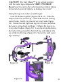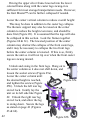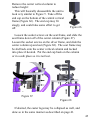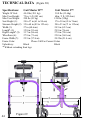
1
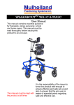
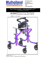
839 Albion Ave
P.O. Box 70
Burley, ID 83318
USA
(800)-543-4769
User’s Manual(IFU): GAIT MASTER I & IITM
U.S. PATENT NO. 7,275,554 B2
EC REP
Wellkang Ltd (www.CE-marking.eu),
29 Harley St., London W1G 9QR, UK
MHRA #: CA 012023
Product Code: I2
Product Category: Walking Aids & Wheelchairs
1
TABLE OF CONTENTS
Preface/Design Goals
3
Components
4
Precautions
6
Assembly
7-15
Assembly Instructions
Fitting Instructions
15
Measuring The User
15
Preparing The Unit
16
Tilt Adjustment
22-23
Options
24
Gas & Coil Springs
24
Abduction Seat
24
Front Caster Anti-Swivel Lock & No-Backs
25
Head, Neck, & Shoulder Support
25
Seat Support Frame Only
25
Pelvic Support
26
Leg Extensions
26
Getting In & Out
26
Assisted Entry
26
Unassisted Entry
27
Assisted Exit / Unassisted Exit
Fine Tuning
2
9
34
37
Spring Lock-Out
39
Cable Adjustment
39-40
Collapse & Transportation
Technical Data
40-43
44-45
Maintenance
45-46
READ ENTIRE MANUAL BEFORE USE!
PREFACE
This booklet provides information to professionals for
the setup and use of the child and adult Gait Master™.
The benefits of using the system can be profound, not only
in terms of gait development, but also in terms of
increasing the user’s independence, self-confidence, and
social interaction. The Gait Master™ provides upper body
support along with weight relief as the user develops gait
skill and tolerance.
DESIGN GOALS
The Gait Master™ is designed to give the user the
potential of hands-free, self-initiated movement while
providing lateral support and assisted lift. A two-part
spring assisted lift allows for dynamic weight relief
throughout the entire gait, and assists the user up to and
down from a standing position. Extreme adjustment of the
seat, thoracic, and sternum supports are possible with quick
and easy adjustments. If deemed allowable by a
professional, a user can get into, out of, and secure
themselves in the Gait Master™ with no outside
assistance. Additionally, adjustment of seat height and
thoracic supports are possible while the user is secured in
the unit, and the fine-tune seat height control can be easily
controlled by the user while they are in the Gait Master™.
3
COMPONENTS
Refer to Figure 1
1. Sternum Support
2. Thoracic/Upper Back Support
3. Pelvic Support
4. Seat
5. Upper Frame (silver)
6. Brake Handle
7. Caster Anti-Swivel Lock
8. Caster Wheel
9. Bumper Wheel
10. Pull Knob
11. Lower Frame (colored)
12. Gas Spring Height Adjustment Lever
13. Center Vertical Column
4
1
2
13
3
4
5
12
6
11
10
7
9
8
Figure 1
5
PRECAUTIONS
1. Standing and or gait training is only carried out under the
prescription of the user’s physician along with the
recommendations for duration, frequency, and
contraindications.
2. A therapist must always be present while the Gait
Master™ is in use, unless a physician and therapist have
authorized independent use of the Gait Master™ to the
user.
3. The Gait Master™ can tip over if used by a tall
individual with poor upper body control.
4. Best if used on level surfaces, and be moved slowly up/
down handicap approved ramps only.
5. Do not use for transportation in vehicles or as a push
stroller.
6. Check all knobs, latches, and screws that are used for
body positioning adjustments before every use to ensure
they are securely fastened.
7. Periodically check all fasteners, and tighten any loose
fasteners. Loose fasteners can cause the Gait Master™
to be inoperable.
8. Check each of the four caster legs to check that they are
locked and cannot swivel before the user gets into the
unit.
9. The thoracic supports and rear seat pad bar must be
locked into position at all times during use, unless the
user is getting into or out of the Gait Master™.
10.Secure the rear leg straps so they do not drag on the
floor during use.
11.Do not put fingers or body parts in/near joint pinch
points or holes during operation.
6
ASSEMBLY
General Information
Tools Required
3/16” Allen Wrench (included in tool pouch)
5/32” Allen Wrench (included in tool pouch)
1/8” Allen Wrench (included in tool pouch)
Tape Measure
Sliding Knobs
The sliding knobs are found on the thoracic ring support,
and the rear seat pad. These knobs slide along the length
of the tube, and automatically lock into place. Push the
round black knob along the length of the tube and away
from the hinge joint. Rotate the hinge joint outward and
release the knob. Refer to Figure 2.
To lock the knobs back in
place: swing the arm containing
the knob to its locked position.
The knob will automatically lock
into place.
Figure 2
7
Pull Knobs
Pull knobs are found on the lower frame. Behind the
round knob is an “X” shaped slot. These slots act as a
guide for a retaining pin attached to the pull knob. Pull the
round black knob out so the retaining pin is free. Rotate
the knob 90 degrees so the retaining pin lines up with other
slot. Release the knob and allow the retaining pin to slide
into the slot. The pull knob is in the “locked position”
when the retaining pin is in the deeper of the two “X” slots.
Refer to Figure 3.
Locked
Retaining Pin
Unlocked
Figure 3
8
Allen Screws
All other adjustments are
comprised of allen screws.
Insert the short end of the
appropriate allen wrench into
the socket of the allen screw.
Tighten or loosen the screw
by turning the allen wrench.
Figure 4
Assembly Instructions
Unpack and unwrap all of the parts. Depending on your
specific order, your parts may differ than the ones shown
below.
Figure 5
9
Unwrap the two black straps that keep the caster legs
together, and rotate the legs to an open position as shown
in Figure 1. The caster legs do not automatically lock into
place. Put away the straps by wrapping them around the
leg and looping the strap through the two D-rings.
Lock the caster legs in place. Rotate the rear leg pull
knobs so the retaining pin is aligned with the deepest slot.
Release the knob. It is ok if the knob does not slide all the
way into the slot. Rotate the caster leg back and fourth
until the retaining pin locks the leg in place. Refer to
Figure 6, note that the location of the slots may not be
depicted as in the figure.
Locked
Unlocked
Figure 6
The front and rear caster legs have two locking pins
each. The locking pins are located at the center of the legs.
It is highly recommended to have all leg locking pins
engaged when using the unit.
10
Having the four leg locking pins engaged during use
increases stability of the unit, especially for outside use.
If the silver and colored frames are not
together: Confirm that the pull knobs
near the top of the square tubes are in
the unlocked position (retaining pin is
in the shallow slot) as shown in Figure
7. If they are in the locked position, the
upper frame will not slide into the lower frame. Figure 7
Actuate the gas springs* to make insertion of the upper
frame into the lower frame easier (This may have already
been done for you before the unit was
packaged). Pull the ring toward the front of
the unit while rotating the gas spring release
lever toward the right side of the Gait
Master ™. Refer to Figure 8. The ring may
by released once the handle is vertical.
Pull
Continue to rotate the handle until both gas
springs stop rising out of the square tubes.
Figure 8
*Caution, the gas springs
will extend upward out of
the opening of the square
tubes (Figure 9), and can
do so with much force and
speed. Keep clear of the
opening of the square tubes while
actuating the gas spring release
handle.
Figure 9
11
Insert the upper frame into the lower frame. Make sure
the “U” shape of the silver round tube is pointing toward
the front of the lower frame. Insert the silver vertical
square tube over the black round gas spring. Refer to
Figure 10. Continue to slide the upper frame down and
into the square tube of the lower frame. Fixed inside the
larger square tube of the lower frame are plastic inserts.
These pieces fit snugly between the two square tubes. If
the silver square tube does not immediately slide past the
plastic inserts, put slight pressure on the silver square tube
to help align it in place. When aligned properly, the upper
frame should easily slide down into the lower frame.
Forcing the upper frame into the lower frame when not
properly aligned can cause damage to the plastic inserts.
Figure 10
12
Rotate the thoracic support so the front pads are about 4
inches (10 cm) lower than the rear curved pads. Loosen
the four allen screws on the central block, only one or two
turns is necessary. Rotate the support arms and tighten all
four allen screws firmly.
Rotate
Screws
Figure 11
Insert the center vertical column into the top of the
square opening in the center of the upper frame. Remove
the end-cap from the column. Slide the center vertical
column into the square opening.
Make sure that the nuts attached to
the screws can slide into the
groove of the vertical column. It
may be necessary to rotate the
screws a few turns to line up the
nuts correctly. Slide the center
column toward the floor until
Screws
about 5 inches (13 cm) extends
below the square opening. Firmly
tighten both of the screws located
on the side of the square tube until
the column is securely in place.
Figure 12
13
Attach the seat to the center
vertical column. Slide the open
square tube attached to the seat
frame up around the center vertical
column. Make sure the nuts
attached to the allen screws are
aligned so they can slide into the
groove of the center column. Stop
when about a 1/2 inch (1.5 cm) of
the column extends below the
square tube. Firmly tighten the
allen screws until the seat is
securely in place.
Figure 13
Attach the end cap of the center
column. Push the cap into place until it
cannot go any further.
Figure 14
If the pelvic support came with your unit, attach it now
to the vertical column. Place the pelvic support below
the thoracic support and above the upper frame to the
desired height. The pelvic support is attached by firmly
tightening the allen screws located behind the pelvic
support. See Figure 14b for details.
14
Figure 14b
FITTING INSTRUCTIONS
Measuring The User
#1: Inseam + 2in: ________
#2: Crotch to Tip of the Sternum* - 2in: ________
#3: Chest Width + 1in: ________
#4: Chest Depth + 2.5in: ________
*This measurement can be changed for the most effective
area of the sternum pad placement; either, below, across,
or above the breast area.
15
Preparing The Unit
The design of the Gait Master™ allows for a wide range
of users. This section explains the basic steps in getting
the unit in an arrangement that will allow the user to
comfortably get in/out and use the device. Additional
“fine-tuning” can be done based on preference and user
feedback (see Fine Tuning section). During preparation,
the user should NOT be placed in the Gait Master™ at any
time!
First, make sure the upper frame is free to slide up and
down inside of the lower frame. On each side of the lower
frame near the top of the square tube is a pull knob (Figure
7). This knob allows the upper frame to be locked to the
lower frame (No spring action). When the retaining pin is
in the shallow slot, the upper frame is able to slide in and
out of the lower frame when downward pressure is applied.
This is what is desired at this time. If the pull knob does
not come out when you pull it, try putting downward
pressure on the upper frame while you pull the knob out.
Gas Spring Handle Operation
The gas spring release handle has a
locking pin to prevent accidental actuation
of the gas spring. The handle can be placed
in two main positions (see next page). Use
the pull ring to change handle positions.
Pull
Figure 15
16
Position 1, the handle is in a vertical locked position. It
cannot rotate, and does not actuate the gas spring (Figure
16a). Position 2, the handle is in a vertical un-locked
position. It can rotate, and will actuate the gas spring when
rotated toward the right of the unit (Figure 16b).
Fixed vertically
Figure 16a
Movable with activation
Figure 16b
Position 1 is to be used to help prevent accidental
actuation of the gas spring by the user. Position 2 allows
the handle to actuate the gas spring without having to use
the locking pull pin (Figure 15).
To actuate the gas spring (raise the upper frame), rotate
the handle to the right of the unit (Figure 16b). The further
the handle is rotated, the faster the spring will raise the
frame. The handle can be released at any time, and this
will lock the position of the upper frame in its current
location (The upper frame can still move up/down due to
the coil spring).
17
Preparing The Unit (con.)
Adjust the angle of the sternum support to a
position similar to Figure 17. Use the allen
wrench to loosen/tighten the four screws. The
angle of the sternum pad can be adjusted
further once the user is in the unit. Do not
place the user in the unit at this time!
Screws
Figure 17
Adjust the distance between the sternum
pad and the seat so it is equal to measurement
#2 as shown in Figure 18 by moving the seat frame up/
down on the center column.
Confirm that the seat height can be reached. Actuate the
gas spring so the upper frame rises until it comes to a stop.
The gas spring has a
7.9in (20cm) stroke.
Measurement #1
#2
should be in between
the value of #5 (Figure
18) and #5 - 7.9in.
#5 ≥ #1 ≥ (#5 – 7.9in)
18
If this relationship is
not true, adjust the
location of the center
mast on the upper
frame using the screws
shown in Figure 18
until the relationship is
valid.
#5
Figure 18
Adjust the height of the thoracic support so about 7
inches (18 cm) separates the sternum pad and front
thoracic pad. Loosen the four allen screws located on the
center block to slide the thoracic support up/down as
shown in Figure 20. The location of the thoracic support
can be adjusted further when the user is in the unit. Do not
place the user in the unit at this time!
~7in
Figure 19
Figure 20
Adjust the width of the thoracic support so it is equal to
measurement #3 as shown in Figure 21. Loosen the two
allen screws located on the underside of the front thoracic
pads. Make sure the distance from the center vertical
column to the left and right sides of the thoracic pads are
equal for symmetric support.
#3
Figure 21
19
Adjust the depth of
the thoracic support so it
is equal to measurement #4 as
shown in Figure 22. Loosen/
tighten the two allen screws
located on
the underside of the foam
padding.
Figure 22
#4
The width and depth of the thoracic support can be
adjusted further when the user is in the unit. Do not place
the user in the unit at this time!
Additionally, the thoracic support can be tilted in any
angle to maximize proper support. A good starting angel is
about 20 degrees up from the floor. To modify the angle,
loosen the top two allen screws on the center thoracic
block. Adjust the thoracic angle, and tighten the screws
firmly (Figure 23).
Screws
Figure 23
20
For unicycle style type seats:
The seat can be slid along the seat support frame. Start
by having the nose of the seat approximately 1inch (2.5
cm) from the center vertical column. To adjust the seat
position, loosen the T-screw, and slide the seat (Figure 24,
a). Then, tighten the screw.
The pitch of the seat can be adjusted. Loosen the four
nuts located under the seat (tool not provided) and tilt the
seat. Tighten the nuts (Figure 24,b).
b
a
b
a
b
Figure 24
Tapered style seats (not shown) cannot be adjusted on the
seat support bar.
The rear seat pad can be adjusted up/down and front/
back. Exact placement of the pad is user preference.
To adjust the pad up/down, loosen the two allen screws
on the block attached to the back of the pad. Slide the pad
up/down, and tighten the screws (Figure 25).
21
To adjust the pad front/back, disengage the sliding lock
behind the seat, and allow the pad to swing down (Figure
26). Loosen the now exposed hex head bolt until the tube it
is attached to is free to slide (tool not included). Move the
bar to the desired position, and tighten the allen screw.
Swing the pad back up into place.
IMPORTANT: Make sure the rear seat pad arm can lock
back into place after each rear seat pad adjustment!
Figure 25
22
Figure 26
The tilt adjustment feature is a new feature added to all
Gait Master™ units. When the human body walks, it has a
natural tendency to lean forward. With every step taken
the upper body will shift or lean slightly forward. The tilt
adjustment feature allows the vertical column of the unit to
tilt slightly forward by a few degrees. When the vertical
column moves, the sternum, thoracic, and pelvic supports
move with the column. This new feature will simplify
walking in the Gait Master™.
Jam nut
Locknut
Figure 27
To use the tilt adjustment, start by loosening
the bottom locknuts located on the upper frame,
you will need a 9/16 size
wrench to do this. See
Figure 27 for details.
Make sure the user is not
in the unit at this time.
Also, make sure both
locknuts, one on each
side of the unit, are loosened the same distance.
Once the locknut is loosened, tilt the upper frame,
this will tilt the column
as well. Tighten the
locknut, the upper jam
nut may need to be tightened as well.
Not Tilted
Tilted
The basic setup of the Gait Master™ is now complete.
For instruction on how to get in and out of the Gait Master™ see the Getting In & Out section. For fine tuning, see
the Fine Tuning section.
23
OPTIONS
Gas & Coil Springs
When a Gait Master™ is ordered, we request the user’s
weight in order to assist you in choosing the correct gas
and coil springs for the unit. The main purpose of the gas
springs is to allow for easy adjustment of the seat height
while the user is in the unit, weight-relief for the legs, and
to provide supportive assistance to the user during the sitto-stand and stand-to-sit positions. Depending on the
user’s weight, a specific pressure of gas spring is installed
on the Gait Master™. The gas springs on the unit are
capable of handling a range of user weights. However, a
Gait Master™ ordered for a light-weight user may not be
suitable for a second heavy-weight user. Gas springs are
not changeable in the field. If desired, the lower frame of
the unit can be sent back to the manufacture to have a
different pressure of gas spring put in.
Coil springs, like gas springs, are ordered with the unit
based on the user’s weight. They allow for the dynamic
up/down motion of the upper frame while the user takes a
step as well as weight relief for the legs. Coil springs can
be changed in the field if need be.
Abduction Seat
The abduction seat is a modified tapered seat. The seat
has elongated sides which helps to prevent the user’s legs
from abducting.
24
Front Caster Anti-Swivel Lock
This option allows either of the front casters to be locked
so they only track in a forward/reverse direction. These
locks are similar in appearance and usage to the standard
rear caster swivel locks.
No-Backs
No-Backs prevent the rear wheels from rotating
backward. The rear swivel locks need to be engaged at the
same time as the no-backs to keep the Gait Master™ from
rolling backward.
Head, Neck, & Shoulder Support
Many of our adaptive components used for head, neck,
and shoulder support can be added onto the Gait Master™.
The rear seat pad assembly is replaced by a removable
rigid padded vertical support bar where shoulder pads,
neck rests, and head pads can be attached.
Seat Support Frame Only
This option is for users who have excellent upper body
control, and do not require the use of the thoracic and
sternum supports.
25
Pelvic Support
The pelvic support is a wide padded belt-like support
that securely controls the user’s pelvic area. It is width and
depth adjustable, and has velcro and snap-buckle closures.
Leg Extensions:
Refer to the pictures below.
To extend the base of the Gait MasterTM simply pull up on
the ring (1) and slide out the extension tube to the desired
length. Both sides should be set to the same length. Push
the pin back in place.
Caution: Adjust the length to suit the conditions of use.
Extend the legs for play or outdoor use. The Gait MasterTM
may become unstable if the legs are too short for the
conditions of use.
1
GETTING IN & OUT
Assisted Entry
Same as unassisted entry, except a therapist provides
assistance at all times to safely get in.
26
Unassisted Entry
CAUTION!
Unassisted entry is ONLY allowed with the permission
of a THERAPIST, and ONLY after the user has gotten in
and out of the unit with the assistance of a therapist!
Preparing The Unit
Place the Gait Master™ is on a firm, level surface.
Unlock the upper and lower frames from each other if not
already done so. The seat must be in the lowered position
via the gas spring handle. The seat should already be in
the lowered position because the user actuated the gas
spring handle and lowered the seat in order to get out. If
the seat is not lowered, apply downward force on the seat,
and push and hold the gas spring handle to the side (Figure
16). Allow the seat to lower until it stops. Release the gas
spring handle. Lock both of the rear wheel brakes by
pressing down and slightly in on the two brake levers
(Figure 28). The brake handle will self-lock.
Unlocked
Locked
Figure 28
27
For the Gait Master I™ brakes refer to Figure 28b.
Unlocked
Locked
Figure 28b
If the rear caster swivel lock is desired, use the pull knob
on the back of the caster to lock them in place. Align the
retaining pin with the deeper slot (Figure 29). Make sure
the swivel is locked! Rotate the caster until the pull knob
pin mates with the hole on the caster fork.
Note: The caster swivel locks cannot be adjusted by the
user once they are in the unit!
28
Figure 29
Lower the rear seat pad. Pull up on the black round knob
on the end of the seat support bar, and allow the pad to
swing down and hang (Figures 30 & 31).
Figure 30
Figure 31
Open the thoracic support. Pull the black round knobs
toward the rear of the unit, and swing the arms to the front
(Figures 32 & 33).
Figure 32
Figure 33
29
Getting In
Approach from the rear, and get as close to the seat as
possible (Figure 34). However, do not get so close so that
the chair you are sitting on
blocks the “swing up” of
the rear seat pad. One
option is to have the rear
seat pad rest on top of the
chair seat and in-between
the user’s legs. This allows
the Gait Master™ to be
closer to the chair, and will
not hinder the “swing up”
of the pad.
Figure 34
The seat the user is in must be FIXED and not able to
move! For example, lock the wheels of a wheelchair. A
standard 4-leged non-caster chair will also work.
The user may wish to
move toward the front of
the seat they are sitting in to
get closer to the Gait
Master™, as this may assist
in the transfer (Figure 35).
Do not get so close to the
edge of the chair as to fall
off!
Figure 35
30
Grab a the silver round tube of the Gait Master™ with
both hands (Figure 36). In your own best way, stand/lift
yourself out of the chair, over the back of the Gait
Master’s™ seat, and down into the seat (Figure 37). Do
not let go of the frame!
Figure 36
Figure 37
Lean forward and rest against the sternum pad for
support (Figure 38). Let go of the silver frame with your
non-dominant hand only, and close the side of the thoracic
support of that same side (Figure 39). Make sure it locks
into place!
Figure 38
Figure 39
31
Grab the silver frame so that the just closed thoracic side
support is between your torso and inner-arm (Figure 40).
With your dominant arm let go of the silver frame, and
reach around to the back of the seat. Swing up the rear seat
pad (Figure 41). Make sure the pad locks into place!
Figure 40
Figure 41
Close the other side of the
thoracic support (Figure 42).
Make sure it locks into place!
You may now completely let
go of the silver frame.
Figure 42
32
Push the gas spring handle to the right as you straighten
your legs to a standing position * (Figures 43 & 44).
When you are at the peak of your stance, release the lever.
The seat will now be at the standing height, and you will
feel an upward pressure from the seat. If you totally relax
your legs, the seat will only move down about 2 to 3 inches
(5.1 to 7.6 cm).
When you are ready to move, release the two rear caster
brakes. Pull up on the two brake handles (Figure 45). The
handle will stay in an upward position. You are now freely
to move around in the Gait Master™!
Pull
Figure 44
Unlock
Figure 43
Figure 45
* NOTE: The blue frame shown in these photographs is an
early model of the Gait Master™. It’s gas spring handle is
located on the silver frame. The lavender models shown
depict the gas spring handle and frame setup for the 2006
production.
33
Assisted Exit
Same as unassisted exit, except a therapist provides
assistance at all times to safely get out.
Unassisted Exit
CAUTION!
Unassisted exit is ONLY allowed with the permission of
a THERAPIST, and ONLY after the user has gotten in and
out of the unit with the assistance of a therapist.
Getting Out
Position the Gait Master™ so that a FIXED chair is
directly behind you (Figure 46), and lock both of the rear
brake levers (Figure 28).
34
Figure 46
Push and hold the gas spring
handle to the right, and relax your
legs so all your weight is on the
seat of the Gait Master™. Your
body weight will push the seat
down * (Figures 44 & 47). When
the seat stops, release the gas
spring lever.
*See note on page 33
Figure 47
Grab the silver frame with your
non-dominant hand. Do not let go
until stated to do so! With your
dominant hand, release the thoracic
ring of that side (Figure 48).
Figure 48
With your dominant hand, reach
around to the back of the seat and
release the rear seat pad (Figure
49). It is ok if the seat pad comes
to rest on top of the chair you are
about to sit on.
Figure 49
35
Grab the silver frame with your
dominant hand. Do not let go
until stated to do so! Let go of
the frame with your nondominant hand, and release the
other side of the thoracic ring
(Figure 50). Again, grab the
silver frame with both hands for
support!
Figure 50
From this point on, at least one of the user’s hands must
be firmly held on to the silver frame at all times to provide
upper body support!
In the best way possible, lift up off the seat, back toward,
and down into the FIXED waiting chair (Figures 51 & 52).
Once you are secure in the chair, you may completely let
go of the Gait Master™. If desired, close and lock the rear
seat pad and thoracic ring in place.
Figure 51
36
Figure 52
FINE TUNING
After preliminary adjustments are made, and the user has
gotten into the unit, some readjustment may be needed. All
adjustments can be made while the user is in the Gait
Master™ WITH THE FOLLOWING EXCEPTIONS:
DO NOT adjust the seat frame on the center vertical
column while someone is in the unit! (Figure 53)
DO NOT adjust the rear seat pad forward/backward
while someone is in the unit! (Figure 54)
DO NOT adjust the center vertical column in relation to
the upper frame while someone is in the unit! (Figure 55)
Figure 53
Figure 54
Figure 55
37
Common adjustments made to the Gait Master™ while
someone is in it include:
Thoracic width and depth: Use the screws on the
underside the pads to adjust the width and/or depth
(Figures 57 & 58). If the user does not have good upper
body control, it is suggested to have the thoracic support fit
snugly around the chest to prevent extreme shifts of their
center of gravity. Also, you may adjust the angle of the
thoracic support by loosening the screws in the center
clamp block. This may be difficult if to do while the user
is in the unit if there is little room between the clamp block
and the user’s chest/abdomen area.
Figure 57
Figure 58
38
Figure 59
Spring Lockout
The upper frame and lower frame
can be “locked-out” so there is no
vertical movement between the two
frames. This can be done while
someone is in or out of the unit.
Lock the frames together:
Figure 60
Orient the center knob on the
left and right side of the
lower frame into its locked
position (Figure 60). Push
down on the upper frame
until the knobs click into
place (Figure 61). The
upper frame should now
not be able to move up or
Figure 61
down.
If only one knob engages, some slight up/down movement
of the non-engaged side of the upper frame should align
the pin.
DO NOT operate the gas spring lever when the frames
are locked together! Doing so may make pulling the knobs
out to unlock the frames very difficult!
CABLE ADJUSTMENT
The tension in the gas spring and brake cable may need
to be adjusted after a period of time. The following
information will show how to tighten the cables.
39
You will need a 7/16 size wrench to loosen the nut on
the gas spring or brake cable. Loosen the bottom nut for
the gas spring cable, and the rear nut for the brake cable.
See Figure 56 & 56b for details. Once the nut is loosened,
softly pull the covered part of the cable as needed to add
tension to the cable. Tighten the nut once you are finished.
Figure 56
Figure 56b
The handle stop is an “L” shaped
bar used to stop the gas spring handle
from rotating too far to the right. After
a period of time the handle stop may
need to be adjusted. To move the handle stop, unloosen the set screw at the
top of the pivot block using the appropriate allen wrench. After, slide the
handle stop to the right, just enough to
allow the handle to actuate the gas
springs. See Figure 56c for details.
Set Screw
Figure 56c
COLLAPSE & TRANSPORTATION
The Gait Master™ can be collapsed for storage or transportation. There are several ways to accomplish this. No
one may be in the unit during or after any of the steps in
40 this section!
CAUTION! The Gait Master™ in its vertical position
with the caster legs collapsed is VERY UNSTABLE!
Do not store the unit in the vertical position without taking
precautions to prevent tipping, as damage may result!
Swing the legs in to reduce overall length:
Lock the frames together (Figures 60 & 61). Undo the
straps on the rear caster legs. Unlock the two left side leg
swivel locks. Gently, lay the unit on its left side (Figure
62). Unlock the two right side leg swivel locks, and allow
the legs to swing down and hang. Collapse the legs in an
every-other fashion (Figure 63). Loop the strap attached to
the back left leg around the front left leg, and tighten it by
use of the two D-rings (Figure 64). Secure the right caster
legs similarly.
Figure 62
Figure 64
Figure 63
41
Having the upper silver frame lowered into the lower
colored frame along with the caster legs swung-in is
sufficient for most storage/transportation needs. However,
the Gait Master™ can be further collapsed if needed.
Lower the center vertical column to reduce overall height:
This may be done in addition to the caster leg collapse.
The thoracic support may also be raised on the center
column to reduce the height even more, and should be
done first (Figure 20). It is assumed that the legs will also
be collapsed in this section. Lock the frames together
(Figures 60 & 61). The lowered position of the center
column may obstruct the collapse of the front caster legs,
and it may be necessary to collapse the two front legs
before the center column is lowered. If this is so, firmly
secure the unit so it will not tip over when the front caster
legs are swung inward.
Unlock and swing in the front legs. Hang on to
the center column so it does not shift down, and
loosen the socket screws (Figure 65a).
Lower the center column until
the desired height is reached,
Figure 65a
and tighten the screws (Figure
65b). Unlock the left rear leg
swivel lock. Gently lay the
unit on its left side like Figure
62. Unlock the right rear leg
swivel lock, and allow the leg
to swing down. Secure the legs
as stated on page 41 (Figures
63 & 64).
42
Figure 65b
Remove the center vertical column to
reduce height:
This will basically disassemble the unit to
look very similar to Figure 5. Take off the
end cap on the bottom of the central vertical
frame (Figure 66). The end cap may fit
snugly, and could take some effort to get
off.
Figure 66
Loosen the socket screws on the seat frame, and slide the
seat frame down off of the center column (Figure 67).
Loosen the socket screws on the silver frame, and slide the
center column up and out (Figure 68). The seat frame may
be slid back onto the center vertical column and locked
into place if desired. Put the end cap back on the column
or in a safe place so it is not lost.
Figure 67
Figure 68
If desired, the caster legs may be collapsed as well, and
done so in the same manner as described on page 41.
43
TECHNICAL DATA
Specifications:
(Figure 69)
Gait Master II™
Gait Master I™
Weight Of Unit:
44.4 lbs (20.1 kg)
30.0 lbs (13.6kg)
Max User Height:
72 in / 6 ft (183 cm)
60in / 5 ft (152.4cm)
Max User Weight:
200 lbs (91 kg)
120 lbs (55kg)
Seat Height (1):
24 to 37 in (61 to 94 cm)
17 to 30 in (43 to 76cm)
Sternum Height (2): 35 to 60 in (89 to 152 cm)
28 to 53 in (71 to 135cm)
Width (3):
27 in (68.6cm)
24.5 in (62.2 cm)
Length* (4):
35.8 in (91 cm)
29.9 in (76 cm)
Rigid Length* (5): 33.7 in (86 cm)
27.8 in (70.6 cm)
Wheelbase (6):
27.9 in (71 cm)
22.0 in (56.0 cm)
Frame Width (7):
22.5 in (57.2cm)
20.25in (51.4 cm)
Frame Color:
Please Call For Current Colors
Upholstery:
Black
Black
* Without extending front legs
2
1
7
3
44
Figure 69
4
5
6
Materials
Frame:
Parts:
Padding:
Fabric:
Bumpers:
Wheels:
Powder-coated steel tube
Stainless steel tube
Black anodized aluminum
Zink plated steel
Powder-coated steel
Black anodized aluminum
Neoprene foam, spongy foam
Nylon packcloth
Solid gray cushion rubber with delrin bearing
Solid gray cushion rubber with double seal
ball bearings
MAINTENANCE
Keep the unit clean. All parts can be washed with a mild
concentration of soap and water. Rinse and dry with a
towel.
Check weekly for loose screws and nuts. Firmly tighten
as needed.
Over a period of time the rubber on the wheels will
slowly start to wear off. In this case, the plunger head in
the braking system will need to be lowered to grip the
wheel with more power during braking. To adjust or lower
the plunger head you will need to take the caster wheel off.
After the wheel is off you will need a pair of pliers to grip
the plunger head. Turn the plunger head counter-clockwise
to lower it. Only a few turns is necessary. Make sure the
user is not in the unit at this time. Adjust the plunger head
on both rear legs the same distance!
45
Attach the caster wheels back on when you are finished.
See Figure 70&70b for details.
Plunger head
Caster Wheel
Figure 70
Figure 70b
If there is a problem you cannot fix, discontinue use and
contact your distributor or Mulholland Positioning Sys.
Inc.
46
NOTES
47
839 Albion Ave
P.O. Box 70
Burley, ID 83318
48
Phone: (208) 878-3840
(800) 543-4769
Fax:
(208) 878-3841
[email protected]
www.mulhollandinc.com