1
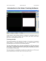
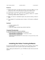
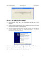
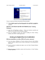
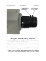
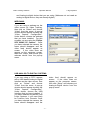
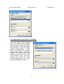
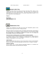
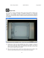
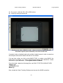
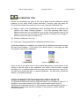
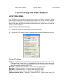
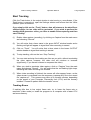
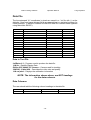
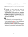
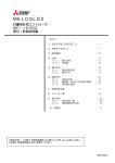
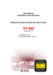
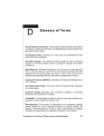
LoliTrack Quatro
Video Tracking
Software
Operation Manual
TABLE OF CONTENTS
INTRODUCTION TO THE VIDEO TRACKING SOFTWARE
Tracking Principle
Features
Included
Computer Requirements
1
2
2
2
INSTALL THE VIDEO TRACKING SOFTWARE
Install the WIBU Key Runtime Kit
Install LoliTRACK Software (Video Tracking Software)
3
4
ANALOG-TO-DIGITAL DEVICE INSTALLATION
Webcam Installation (or other USB or Fire wire cameras)
CCTV Cameras (or other analog cameras)
Typical CCTV Camera and Lens with Auto-Iris Control
5
5
6
USING THE VIDEO TRACKING SOFTWARE
Webcams
USB Analog-to-Digital Systems
PCI Card Analog-to-Digital Systems
7
8
8
VIDEO TRACKING MENUS
Video Capture Configuration Menu
Device
Compression
File Recording
Temp File
Video Settings Menus
Main Menu Options
Zoom
Video Mode
9
9
9
9
9
9
10
10
10
PREPARE FOR TRACKING
Display Tool
Threshold
Cross
Trace
Length(s)
Noise Filter Tool
Thresholds Tool
Mask Tool
Multible object tracking (domains)
Calibration Tool
11
11
11
11
11
11
12
13
14
15
LIVE TRACKING AND VIDEO CAPTURE
Live Tracking
Start Tracking
Tracking Errors
Data File
Data in Text File
Data Columns
Video Capture
To Make a Video Capture
Tracking Pre-Recorded Video
16
18
18
19
19
19
20
20
21
MONITORING TRACKING RESULTS
Input
Total Input Frames
Skipped Frames
Input Frame Rate
Output
Total Output Frames
Output Utilization
Output Frame Rate
Results
Position (pixels) (X,Y)
Tracked pixels
Velocity (pixels/s)
Time Averages (milliseconds/frame)
Input Time (ms/f)
Output Time (ms/f)
Process Time (ms/f)
22
22
22
22
22
22
22
22
23
23
23
23
23
23
23
23
Video Tracking Software
Operation Manual
Loligo Systems
Introduction to the Video Tracking Software
Loligo Systems’ video tracking software is designed for automated analysis of
behavior in a wide range of setups, such as mazes, open fields, home cages,
swim tests, activity/preference boxes, etc.
Tracking principle
The program operates on the principle of contrast, i.e. the object to be tracked is
placed against a contrasting background and the software assigns a (x,y)
coordinate pair to the centroid of the contrasting object(s).
The input video images (color or b/w) are converted into a 256 gray scale tone
video output. The program then finds all pixels within the range of a minimum
and maximum threshold value (0-256) for each frame and calculates the center y
& y coordinates of these pixels.
The time-stamped x,y-coordinates are written into a data file up to 60 times per
second, depending on the frame rate of the video input source.
-1-
Video Tracking Software
Operation Manual
Loligo Systems
Features
(1) Multiple video inputs, e.g. digital video camera or files (AVI, MPEG, etc.) and
analog video (VHS, VCR, camcorder) through a video capture device
(2) Track position of an animal in real-time (up to 30 times per second)
(3) Online data export via serial port for triggering devices for operant
conditioning, demand-feeder, shuttle box etc.
(4) Mask tool removes undesirable objects and prevents tracking outside of
arena
(5) Time-stamped X,Y-coordinates saved in simple *.txt file (pixels or calibrated
units)
Included
•
•
•
Software Installation CD
User manual
WIBU-BOX dongle (software copy protection hard key)
Computer Requirements
PC with Windows 2000 or XP and 512 MB RAM
For real-time tracking (25-30 frames/sec) we recommend:
•
•
Video modes up to 320x240 pixels:
PC2100 DDR-RAM, min 2.2 GHz Pentium 4 or AMD Athlon XP 2000+
Video modes up to 720x576 pixels:
PC3200 Dual Channel DDR-RAM, min 2.8 GHz Pentium 4 with HyperThreading or AMD
Athlon 64 3200+
Installing the Video Tracking Software
Do not insert the WIBU Key into the USB port of your computer, until you have
installed the Software, which is located on the Video Tracking Software CD.
Start by placing the software CD in your CD-ROM drive and view the menu that
appears:
-2-
Video Tracking Software
Operation Manual
Loligo Systems
INSTALL THE WIBU KEY RUNTIME KIT
(1)
Ensure that the WIBU key is not connected to the USB port of your
computer.
(2)
Install the WIBU Key Runtime Kit. Follow the directions carefully and install
all of the options that the program suggests.
(3)
Once the installation has completed, insert the WIBU key into the USB port
on your computer and follow the installation procedure. You will be
prompted with the following screen:
Choose “No, not this time”, as the files for installation of the WIBU Key have
already been installed on your computer. Click “Next”.
(4)
You will then be prompted with the following screen:
-3-
Video Tracking Software
Operation Manual
Loligo Systems
Choose “Install the software automatically (Recommended).
(5)
The installation program will prompt you when the installation is complete,
you do NOT have to view the ReadMe.txt file when the installation is
complete.
INSTALL LOLITRACK QUATRO SOFTWARE (Video Tracking
Software)
(1) Install the LoliTrackQuatro software. Follow the directions carefully and
install all of the options that the program suggests.
(2) Once the Installation program has finished installing the Video Tracking
software, click “EXIT” on the original menu.
Analog-to-Digital Device Installation
Webcam installation (or other USB or Fire-wire cameras)
(1) If you are using a Webcam or Fire-wire camera with your video tracking
system, install the camera and its drivers according to the manufacturer’s
instructions.
(2) Once the camera is installed and ready to use, the Video Tracking Software
will recognize it.
(3) When the camera is installed, continue with the section on “Video Tracking
Software Operation”.
-4-
Video Tracking Software
Operation Manual
Loligo Systems
(4) Ensure that you have the camera connected to your computer when running
the Video Tracking Software.
CCTV Cameras (or other analog cameras)
(1) If you are using an analog camera, such as a CCTV camera, then you will
need to install an Analog-to-Digital interface to allow the camera to be
viewed on your computer. Typical interfaces can be purchased from Loligo
Systems and can be either external USB based, or can be internal PCI
based. Notice that analog video cameras and devices are made for either
the PAL or NTSC television standard, e.g. PAL cameras cannot be used with
US type monitors and visa versa.
(2) Install the Analog-to-Digital interface according to the manufacturer’s
instructions.
(3) Connect the camera to the Analog-to-Digital interface before loading the
Video Tracking Software.
Most CCD cameras have very small lenses that produce the “Fish-Eye” effect,
where the edges of the viewing area are bent, due to the curvature of the lens.
Therefore, when using a CCD camera, you should move the camera as far back
as possible and zoom in to get the best quality picture without “Fish-Eye”.
If you are buying a camera for this application, we suggest that you purchase a
good quality CCD camera, or a webcam, with at least a manual focus.
Otherwise, the following options should be considered:
Iris – This controls the amount of light that enters the lens (Auto or manual)
Focus – This allows the user to focus the lens on the image being tracked
Zoom – This allows the user to zoom in on the image being tracked
If you have a camera that possesses all of these features, then the best way to
avoid “Fish-Eye” is to zoom in as close as possible, and then physically move the
camera away from the target, until you can focus on the object. For best tracking
results, and the most resolution, try to fill the screen with the “arena” in which the
object being tracked, will move.
You may have to try a few different
combinations of zoom, focus and physical location of the camera before you
achieve the best location for tracking. If you have any questions at all, please
contact Loligo Systems for help!
Typical CCTV Camera and Lens with Auto-Iris Control
-5-
Video Tracking Software
Operation Manual
Loligo Systems
Using the Video Tracking Software
(1) Insert the WIBU Dongle into the USB port of your computer. The Video
Tracking Software will not run without the dongle!
(2) Ensure that your camera is connected to the computer, either directly by
USB, or through the Analog-to-Digital Interface.
(3) Load the Video Tracking Software by double clicking on the Icon generated
on the desktop when the program was first installed.
(4) You should see the video feed on the computer screen, when the software is
loaded. If you do not see the video screen, then you will have to select the
video source. Follow the instructions below based on the type of camera
-6-
Video Tracking Software
Operation Manual
Loligo Systems
and Analog-to-digital device that you are using (Webcams do not need an
analog-to-digital device, they are already digital!).
WEBCAMS:
If you are using a webcam as the
video source for Video Tracking,
then click on “Select” and choose
“Video” from the menu. A pop-up
window should appear showing the
“Video Capture Configuration”.
Under device, choose the webcam
that you have installed. For this
example, we are using the “Philips
SPC 900NC PC Camera”. Once
you have selected the camera, the
menu should disappear and the
video feed should appear on
screen.
If the video does not
appear on the computer screen,
then click “Setup” and choose your
webcam device from the pop-up
menu.
USB ANALOG-TO-DIGITAL SYSTEMS:
video feed should appear on
screen.
If the video does not
appear on the computer screen,
then click “Setup” and choose your
Analog-to-Digital device from the
pop-up menu.
If you are using a CCTV camera
with a USB based Analog-to-Digital
Interface as the video source, then
click on “Select” and choose
“Video” from the menu. A pop-up
window should appear showing the
“Video Capture Configuration”.
Under device, choose the USB
Interface that you have installed. If
you have obtained this device from
Loligo Systems, it will most likely
be a device from Pinnacle. Once
you have selected the camera, the
menu should disappear and the
-7-
Video Tracking Software
Operation Manual
PCI CARD ANALOG-TO-DIGITAL SYSTEMS:
If you are using a CCTV camera
with a PCI based Analog-to-Digital
Interface as the video source, then
click on “Setup”. A pop-up window
should appear showing the “Video
Capture Configuration”.
Under
device, choose the PCI Interface
that you have installed. If you have
obtained this device from Loligo
Systems, it will most likely be one
from Pinnacle. Once you have
selected the camera, the menu
should disappear and the video
feed should appear on screen.
-8-
Loligo Systems
Video Tracking Software
Operation Manual
Loligo Systems
Video Tracking Menus
VIDEO CAPTURE CONFIGURATION MENU
When you are choosing your video capture device, the Video Capture
Configuration pop-up menu may appear (unless the video feed is automatically
recognized by the software). If this menu does not appear, click “Setup” to view it.
There are a few items of special notice in this menu:
Device: This is the device that you are using to capture images in the software.
Compression: You can choose to compress the video when it is recorded, to
save valuable hard-drive space. If you do NOT choose to “compress the video
when recording” the video files may be extremely large (sometimes a 20
second video can reach up to 300 Mb in size!). If you choose to compress the
video, there will be several options located under the compression window.
Choose the option that best suits your computer (it may take some trial and
error to choose a compression setting that works best for you!).
File Recording: This shows the location of the video file that is being recorded
and saved to your hard-drive. Notice that this file is called “capture.avi” and is
saved in the default location “C:/Program Files/LoliTRACK”. You can change
this location if you wish, but be sure that you know how to find it!
Temp File: This shows the location of the TEMPORARY video file that is being
recorded and saved to your hard-drive. Notice that this file is called
“captemp.avi” and is saved in the default location “C:/Program
Files/LoliTRACK”. You can change this location if you wish, but be sure that
you know how to find it! This file will grow in size as the video is captured and
will be transferred to the “capture.avi” file when capturing is complete. The
longer the video, the more time this process will take when you finish a video
capture. If you notice the program becomes sluggish after you stop a capture,
it is because the program is transferring the data from “captemp.avi” to
“capture.avi”.
VIDEO SETTINGS MENUS
To adjust the frame rate, video mode and image controls, click Capture and then
choose either “Video Capture Filter” or “Video Capture Config”. Use the
appropriate menu options, depending on the video camera or device.
-9-
Video Tracking Software
Operation Manual
Loligo Systems
MAIN MENU OPTIONS
At the top of the video tracking screen, there are several options to consider for
Video Tracking:
Zoom: This allows the user to increase the size of the viewing image on the
screen. This DOES NOT cause the camera to zoom, it simply increases the
size of the image shown in the software. Once the maximum zoom has been
achieved, increasing the zoom will not have any effect on the image viewed
onscreen. Check the “AUTO” zoom feature to enable automatic zoom, in
which the largest image will always be shown onscreen.
Video Mode: This allows the user to select the size, quality and potential type of
compression of the video feed being tracked. The options under this menu will
differ from camera to camera. However, if tracking fails or is sluggish, choose
a smaller video size (i.e. 320x240) or a smaller quality (i.e. 12 bits instead of 16
bits)
Prepare for Tracking
DISPLAY TOOL
Clicking the Display Tool hides and shows the Display options at the top right of
the Video Tracking Screen. On this screen are 4 options:
Threshold - This converts the OUTPUT window into a binary view of white pixels
beyond and blue pixels within the range of the thresholds values.
Cross - an indication of tracked X,Y-coordinates, which appears as a red cross on
the OUTPUT window.
Trace - an indication of tracked X,Y-coordinates, which appears as a red trace on
the OUTPUT window.
Length (s) – This determines the length of the red trace which follows the cross
on the tracked object. The time represents the number of seconds until the
trace begins to erase, AFTER the tracked object has started moving (1-60
seconds).
- 10 -
Video Tracking Software
Operation Manual
Loligo Systems
NOISE FILTER TOOL
Clicking the Noise Filter Tool hides and shows the Noise Filter options at the
middle right of the Video Tracking Screen. This option allows you to reduce any
noise that may be in the field of view of the object being tracked, whether it is in
the foreground or in the background.
Choose:
No Filtering
Linear Filtering (from 2-8)
Spline Filtering (from 2-8)
THRESHOLDS TOOL
Clicking the Thresholds Tool hides and shows the Thresholds options at the
middle to bottom right of the Video Tracking Screen.
Adjust the minimum and maximum bars until all blue pixels are part of the object(s)
you want to track. For a quick scan, choose a difference of 10 and slide the middle
bar up and down. If it is difficult to separate the object from the background
surroundings, consider the following factors:
Contrast between background surroundings and object tracked
It is important to have a uniform background in contrast with the object(s) that you
want to track. Change the “tone” of object(s) or background, e.g. a dark object on
a sheet of white paper (or visa versa) is ideal.
Light/shadow
Use an indirect light source above or next to the arena in order to avoid shadows.
Shades may help to avoid alternating light conditions due to changes in daylight.
Undesired objects
Use the Mask Tool to avoid tracking undesirable objects or to exclude nonrelevant areas outside of the test arena from analysis.
- 11 -
Video Tracking Software
Operation Manual
Loligo Systems
MASK TOOL
Use this tool to remove undesirable objects and prevent tracking outside of the
test arena. For example, consider a zebrafish swimming in a rectangular
aquarium. In this example, there are objects in (or part of) the aquarium which are
in the field of view and are similar in contrast and thus interfere with the tracking of
the zebrafish.
Tracking arena before a MASK is made – observe the similarly contrasted objects
(1) Choose one of the four tools (freehand, line, circle, or square) to draw the
outer limits of where the object to be tracked can move about, e.g. draw a
square around the edges of the aquarium with the fish inside, and the circle
tool to remove objects inside the square.
(2) Then click the paint bucket and fill the outside areas and the insides of the
circles (the dark shaded areas will not be analyzed by the program).
- 12 -
Video Tracking Software
Operation Manual
Loligo Systems
(3) To zoom in, click the 100, 150 or 200 buttons.
(4) Finish by saving the mask file.
Tracking arena after a MASK is made – observe that there are no similarly
contrasted objects (to the zebrafish) in the non-shaded area
If needed, make a detailed mask with multiple shaded areas in order to speed up
the analysis and/or avoid areas with little or no contrast.
If at any time, when you click on the MASK TOOL to create a new MASK, the
menu does not appear, you need to delete some files on your hard-drive. Locate
the folder on your hard-drive: “C:\Program Files\LoliTRACK”
From this folder, delete the following files, and ONLY THE FOLLOWING FILES!
Capture.cfg
LoliTRACK_C.ini
Mask.cfg
Now, reload the Video Tracking Software and resume the MASK operation.
- 13 -
Video Tracking Software
Operation Manual
Loligo Systems
CALIBRATION TOOL
Default x,y-coordinates are given in the unit of pixels and the numbers of pixels
depends on the video mode (image resolution). However, data can easily be
converted into engineering units (e.g. mm or cm) using the Calibration Tool.
(1) Place a ruler in the experimental arena ensuring that the increments are
visible in the Video Tracking Software. If you are capturing video from a
distant source and it is not feasible to use a ruler, then measure some of the
objects in the view and use them a measurement of distance (for example, if
there is a tree in the view, how tall is it?).
(2) Click the Calibration Tool icon.
(3) Follow the 7 Step procedure for calibrating the field of view.
Once the procedure is completed, you should see a calibration area near the lower
left part of the Software. If you click on the “pixels” button, it will toggle the data
from pixels to the units of calibration.
Units in Pixels
Units in Calibration (cm)
Keep an eye on the data shown in the Results data section at the bottom of the
screen to see the data in your calibration unit. Notice, that the data is plotted
according to a co-ordinate plane with the upper left corner being the origin (0,0).
As data move toward the right, x increases positively. As data move toward the
bottom, y increases positively.
USING DOMAINS FOR TRACKING MULTIBLE OBJECTS
It is possible to track more than one object at a time, e.g. one object in each of 1-4
domains. In the output window to the right, click the two Domains icons to
subdivide the visible area into two or four domains. Click and drag the red lines to
adjust the horizontal and vertical boundaries of the domains in which tracking
should take place.
- 14 -
Video Tracking Software
Operation Manual
Loligo Systems
Live Tracking and Video Capture
LIVE TRACKING
Live Tracking is the process by which the object is tracked in real-time. When
performing live tracking, the coordinate data is sent to a .txt file for later analysis.
Notice that Live Tracking does NOT automatically record video. If you wish to
record video and perform live tracking at the same time, ensure that you read the
section on Start Tracking.
If you wish to perform live tracking:
(1)
Setup the software as described in the above sections.
(2)
On the OUTPUT screen, click on Settings and view the following pop-up icon:
Comport Settings
Comport – Default setting at NO COM, meaning that the data is sent to a .txt file.
If a Comport is chosen, the x,y-coordinates will be exported via the serial port
(RS 232). Unless you are using a feedback system for punishment or reward,
leave the comport setting to NO COM.
Baudrate – Default setting at “9600”. Ignore when using NO COM.
Byte Size – Default setting to “8”. Ignore when using NO COM.
Stop Bits – Default setting to “1”. Ignore when using NO COM.
Parity – Default setting to “None”. Ignore when using NO COM.
Communications Mode – Default to Classic:XXXYYY. Ignore when using NO
- 15 -
Video Tracking Software
Operation Manual
Loligo Systems
COM.
Datafile Settings
Write Datafile – Default setting is unchecked. If you wish to perform live video
tracking, check this option. If left unchecked, no data file is generated, and the
Track option on the main screen will be grayed out.
Sample Rate (Hz) – Default setting is 1. This means that the data sampling rate
is 1 sample per second. Regardless of the frame rate, only 1 data point will be
sampled and written to the file per second. If you want to obtain more data
points per second, increase the value. Notice that the maximum is “Output”
which matches the sampling rate to the frame rate of the camera (most often
30 Hz), and the minimum is 0.1.
Window – This shows the location of the data file that is being written to, during
live
video
tracking.
The
default
location
is
“C:\Program
Files\LoliTRACK\LoliData.txt”. You can change the location and name of this
file, but ensure that you keep a record of it.
Add Start Date/Time to filename – This option allows the user to identify the start
date and time of the file. It is suggested that the user leaves this option
checked to help identify the data files.
File Settings
If a file already exists then do the following - Default setting is to “Add a
Number” to the data file. It is suggested that you leave this setting as it, otherwise,
the software may overwrite important data files. By adding a number to the data
file, a list of files will be generated corresponding to the start time of the tracking:
LoliData 2006-05-09 09-56-30.txt
LoliData 2006-05-09 09-57-24.txt
LoliData 2006-05-09 09-58-34.txt
LoliData 2006-05-09 09-59-51.txt
The format for is: LoliData Year-Month-Day Hour-Minute-Second.txt
Forced Scale Settings
Force Processing down to this size if input size exceeds it – The default
setting for this option depends on the camera and computer that you are using.
You do not have to check this option, unless you know the maximum processing
size that your computer/camera combination can handle.
- 16 -
Video Tracking Software
Operation Manual
Loligo Systems
Start Tracking
Click the Track button in the output window to start saving x,y-coordinates. If the
Track button is grayed out, open the Settings window and ensure that the “Write
Datafile” option is checked.
If you simply click on the “Track” button, data will stream to the data file as
outlined above, but no video will be generated. If you wish to perform live
tracking AND generate a video, you have to enable video capturing and then
start Tracking.
(1)
Enable video capture (recording), by clicking on Capture from the main menu
and choosing “Record”.
(2)
You will notice that a timer starts in the green INPUT window header and a
flashing red light will appear to signal that video recording is started.
(3)
Click on “Track”. You will notice that a timer starts in the brown OUTPUT
window header to signal that tracking is started.
(4)
To stop tracking, click on the icon “Stop Tracking”.
(5)
You can start and stop live tracking as often as you wish, without terminating
the video capture, however, the video size will continue to increase
(significantly, if you haven’t chosen to compress the video).
(6)
When you wish to terminate video capture, click on “Capture” from the main
menu and choose “Record”. You will notice that the red flashing light stops,
indicating that video recording has finished.
(7)
When video recording is finished, the screen will often appear frozen, as the
video stream is converted from the temporary (captemp.avi) file to the stored
file “capture.avi”. This process may take up to several minutes, depending
on the speed of your Computer Processing Unit (CPU) and the memory
installed. Please be patient while the transfer occurs.
Tracking Errors
If tracking fails due to low output frame rate, try to lower the frame rate or
resolution (video mode) or install the program on a computer with a faster CPU
and more memory.
- 17 -
Video Tracking Software
Operation Manual
Loligo Systems
Data File
The time-stamped X,Y-coordinates in pixels are saved in a *.txt file with (;) as the
delimiter. Open and parse this text file in any spreadsheet or statistical program for
further analysis. A sample COMMA DELIMITED data file is shown below (opened
using Microsoft® EXCEL).
LoliData v1.3
1.00 Hz
50:18.8
50:19.8
50:20.8
50:21.8
50:22.8
50:23.8
50:24.8
50:25.8
50:26.8
50:27.8
50:28.8
50:29.8
50:30.8
Philips SPC 900NC PC Camera
195
193
164
203
209
174
214
217
219
159
175
207
191
320x240, 12 bits I420
142
144
154
73
79
154
97
114
110
150
162
81
72
1.00 cm/pixel
18560
18397
19589
22687
24844
18858
27472
23938
25187
21341
17741
23933
23990
Data in Text File
LoliData v1.3 – Program used to produce the data file
1.00 Hz – Datafile Sample Rate
Philips SPC 900NC PC Camera – Camera used for tracking
320x240, 12 bits I420 – Describes the video size and quality
1.00 cm/pixel – Displays the calibration information
NOTE: The information shown above, are NOT headings
for the data columns.
Data Columns
The user should add the following column headings to the data file.
Time
50:18.8
X-coordinate
195
Y-coordinate
142
- 18 -
# of Tracked Pixels
18560
Video Tracking Software
Operation Manual
Loligo Systems
VIDEO CAPTURE
Using the Video Tracking software, it is possible to make a video capture or
recording without tracking the object in question. With this option, you can record
the object and then replay the video in the tracking software once, or as many
times as you wish.
Video capture is advantageous for tracking several objects in the same field of
view. Simply record the experiment and then replay the video in the tracking
software and set the threshold to track 1 object at a time. Replay the video as
many times as necessary to track all of the objects (as long as they have
sufficiently different contrast).
To Make a Video Capture
(1)
Load the Video Tracking Software, ensuring that the camera is connected to
the computer.
(2)
Set the Video Capture Filter and Configuration specifications using the
appropriate menus, as described in previous sections.
(3)
Enable video capture (recording), by clicking on Capture from the main menu
and choosing “Record”.
(4)
You will notice that a timer starts in the green INPUT window header and a
flashing red light will appear to signal that video recording is started.
(5)
When you wish to terminate video capture, click on “Capture” from the main
menu and choose “Record”. You will notice that the red flashing light stops,
indicating that video recording has finished.
(6)
When video recording is finished, the screen will often appear frozen, as the
video stream is converted from the temporary (captemp.avi) file to the stored
file “capture.avi”. This process may take up to several minutes, depending
on the speed of your Computer Processing Unit (CPU) and the memory
installed. Please be patient while the transfer occurs.
- 19 -
Video Tracking Software
Operation Manual
Loligo Systems
Tracking Pre-Recorded Video
(1)
Load the Video Tracking Software, ensuring that the camera is connected to
the computer.
(2)
Click on Select from the INPUT window and choose “File…”
(3)
Locate the file on your hard drive and click “Open”.
(4)
The video should appear in the INPUT window. Create a mask or perform
the calibration if need be.
(5)
Set the threshold to track the object in the field of view.
(6)
From the INPUT window, click “Play” to play the video and ensure that the
threshold is set properly to track the object throughout the entire video.
Notice that if the object fails to be tracked at a certain point in the video, you
can alter the thresholds during playback, but it is not advised. Try to set the
threshold so that the object is tracked throughout the entire video!
(7)
Once the video has played entirely through, it will reset back to the beginning,
or you can rewind the video using the controls in the INPUT window.
(8)
When you are ready to begin tracking, click “Track” from the OUTPUT
window. This will simultaneously start playing the video and tracking the
object.
(9)
When the video has completed, tracking will stop automatically. If at any
point during the video you wish to terminate tracking, simply click on “Stop
Tracking” from the OUTPUT window.
When you have finished tracking the video, if you wish to open another video file,
click “Setup” from the INPUT window. A menu will appear allowing you to choose
the new file from your computer.
- 20 -
Video Tracking Software
Operation Manual
Loligo Systems
Monitoring Tracking Results
The Monitor section at the bottom of the Video Tracking Software provides the
user with live information regarding tracking and software performance.
Input
Total Input Frames – This is the total number of frames that have been
processed by the software since the video feed was activated and/or tracking
was started. This number will reset every time you choose a new camera,
reset the video feed or start tracking.
Skipped Frames – This is the total number of frames that have not been
processed by the software, likely due to insufficient memory. Skipped frames
may be a result of excessive sampling rates or overloading the memory with
large video sizes. If your tracking produces large number of skipped frames, it
is suggested that you slow the sampling rate and/or input frame rate.
Input Frame Rate – This is the frame rate from the camera or Analog-to-Digital
Interface. You can change the input frame rate by changing the “Video
Capture Config” and the “Video Capture Filter”. A maximum of 30 fps is
allowed in the Video Tracking Software.
Output
Total Output Frames – The number of frames processed by the software. This
number is the result of the # of Total Input Frames - # of Skipped Frames.
Output Utilization – The amount of memory being used by the program as a
percentage of maximum. If too much memory is being used by the program,
the output frame rate will show as RED and the number of skipped frames will
begin to increase. If this happens, then you need to reduce the Video Mode
(either video size or bitrate) and/or reduce the sampling rate.
Output Frame Rate - This shows the rate of output of frames from the software.
This number should NOT BE RED, if it is then there is not enough memory to
process all of the input frames. You will notice that the number of skipped
frames increases during the time that the Output Frame Rate is RED. If this
happens, then you need to reduce the Video Mode (either video size or bitrate)
and/or reduce the sampling rate.
- 21 -
Video Tracking Software
Operation Manual
Loligo Systems
Results
Position (pixels) (X,Y) - X,Y-coordinates calculated as the geometric centre of
all pixels within the threshold values. This data is saved in the data file, when
tracking is active. If you have used a calibration, the data are shown in the
calibration unit, if selected.
Tracked pixels - The number of pixels within the threshold values. This data is
saved in the data file, when tracking is active.
Velocity (pixels/s) - The velocity (or speed) of tracked object(s). These data are
NOT saved in the data file. If you have used a calibration, the data are shown
in the calibration unit, if selected.
Time Averages (milliseconds/frame)
Input Time (ms/f) – Time required to process the input frames from the camera.
Output Time (ms/f) – Time required to process the output frames from the
software.
Process Time (ms/f) – Total time required to process the video for Video Tracking
(Input + Output)
- 22 -