1
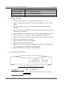
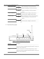
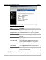
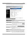
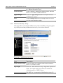
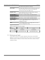
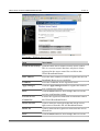
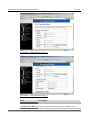
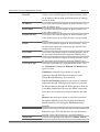
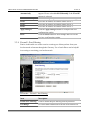
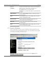
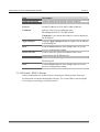
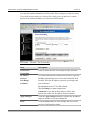
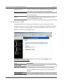
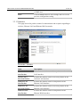
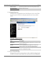
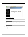
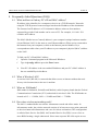
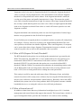
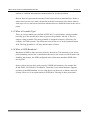
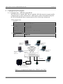
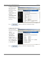
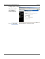
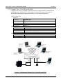
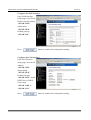
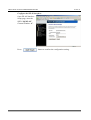
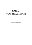
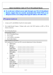
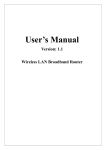
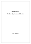
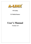
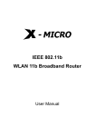
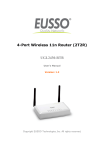
User’s Manual
Version: 2.1
Wireless LAN Broadband Router
Trademarks
Copyright @2003
Contents are subject to change without notice.
All trademarks belong to their respective proprietors.
Copyright Statement
THIS DOCUMENT CONTAINS OF PROPRIETARY TECHNICAL INFORMATION THAT IS THE PROPERTY OF
THIS COMPANY. AND NO PART OF THIS DOCUMENTATION MAY BE REPRODUCED, STORED IN A RETRIEVAL
SYSTEM OR TRANSMITTED IN ANY FORM OR BY ANY MEANS, ELECTRICAL OR MECHANICAL, BY
PHOTOCOPYING, RECORDING, OR OTHERWISE, WITHOUT THE PRIOR WRITTEN CONSENT OF THIS
COMPANY.
USER’S MANUAL OF WLAN BROADBAND ROUTER
Version: 2.1
Revision History
DATE
REVISION
2003/7/16
First release
2003/7/22
Release 1.1; add information about time required on boot-up sequence.
2003/7/24
Release 1.2; modify the boot-up sequence notice in chapter 1
2003/8/4
Release 2.0; add configuration examples
2003/9/5
Release 2.1; support multi-language including English, German and
Spanish, change to DC v7.5 power supply
i
USER’S MANUAL OF WLAN BROADBAND ROUTER
Version: 2.1
Terminology
ANSI
American National Standards Institute
AP
Access Point
CCK
Complementary Code Keying
CSMA/CA
Carrier Sense Multiple Access/ Collision Avoidance
CSMA/CD
Carrier Sense Multiple Access/ Collision Detection
DHCP
Dynamic Host Configuration Protocol
DSSS
Direct Sequence Spread Spectrum
FCC
Federal Communications Commission
FTP
File Transfer Protocol
IEEE
Institute of Electrical and Electronic Engineers
IP
Internet Protocol
ISM
Industrial, Scientific and Medical
LAN
Local Area Network
MAC
Media Access Control
NAT
Network Address Translation
NT
Network Termination
PSD
Power Spectral Density
RF
Radio Frequency
SNR
Signal to Noise Ratio
SSID
Service Set Identification
TCP
Transmission Control Protocol
TFTP
Trivial File Transfer Protocol
WEP
Wired Equivalent Privacy
WLAN
Wireless Local Area Network
ii
USER’S MANUAL OF WLAN BROADBAND ROUTER
Version: 2.1
Table of Contents
REVISION HISTORY .....................................................................................................................I
TERMINOLOGY ........................................................................................................................... II
1
INTRODUCTION.................................................................................................................... 1
1.1
1.2
1.3
1.4
1.5
2
INSTALLATION ..................................................................................................................... 5
2.1
2.2
3
PACKAGE CONTENTS ........................................................................................................... 1
PRODUCT SPECIFICATIONS .................................................................................................. 1
PRODUCT FEATURES ........................................................................................................... 2
FRONT PANEL DESCRIPTION ................................................................................................ 2
REAR PANEL DESCRIPTION.................................................................................................. 3
HARDWARE INSTALLATION ................................................................................................. 5
SOFTWARE INSTALLATION ................................................................................................... 5
SOFTWARE CONFIGURATION ......................................................................................... 6
3.1
3.2
3.3
3.3.1
3.3.2
3.3.3
3.3.4
3.3.5
3.3.6
3.3.7
PREPARE YOUR PC TO CONFIGURE THE WLAN BROADBAND ROUTER ............................... 6
CONNECT TO THE WLAN BROADBAND ROUTER ................................................................ 8
MANAGEMENT AND CONFIGURATION ON THE WLAN BROADBAND ROUTER ..................... 8
STATUS ............................................................................................................................ 8
WIRELESS BASIC SETTINGS .......................................................................................... 10
WIRELESS ADVANCED SETTINGS .................................................................................. 11
WIRELESS SECURITY SETUP .......................................................................................... 13
WIRELESS ACCESS CONTROL ........................................................................................ 14
LAN INTERFACE SETUP ................................................................................................ 16
WAN INTERFACE SETUP ............................................................................................... 17
3.3.8
3.3.9
3.3.10
3.3.11
3.3.12
3.3.13
3.3.14
FIREWALL - PORT FILTERING ......................................................................................... 20
FIREWALL - IP FILTERING ............................................................................................. 21
FIREWALL - MAC FILTERING ........................................................................................ 22
FIREWALL - PORT FORWARDING .................................................................................... 23
FIREWALL - DMZ.......................................................................................................... 25
STATISTICS .................................................................................................................... 26
UPGRADE FIRMWARE .................................................................................................... 27
3.3.15
SAVE/ RELOAD SETTINGS ............................................................................................. 27
iii
USER’S MANUAL OF WLAN BROADBAND ROUTER
3.3.16
4
PASSWORD SETUP ......................................................................................................... 28
FREQUENTLY ASKED QUESTIONS (FAQ).................................................................... 30
4.1
4.2
4.3
4.4
4.5
4.6
4.7
4.8
4.9
4.10
4.11
4.12
4.13
4.14
5
Version: 2.1
WHAT AND HOW TO FIND MY PC’S IP AND MAC ADDRESS? ............................................. 30
WHAT IS WIRELESS LAN? ................................................................................................ 30
WHAT ARE ISM BANDS? ................................................................................................... 30
HOW DOES WIRELESS NETWORKING WORK?...................................................................... 30
WHAT IS BSSID? .............................................................................................................. 31
WHAT IS ESSID? .............................................................................................................. 31
WHAT ARE POTENTIAL FACTORS THAT MAY CAUSES INTERFERENCE? ................................ 32
WHAT ARE THE OPEN SYSTEM AND SHARED KEY AUTHENTICATIONS? ............................. 32
WHAT IS WEP? ................................................................................................................. 32
WHAT IS FRAGMENT THRESHOLD?.................................................................................... 32
WHAT IS RTS (R EQUEST TO SEND) THRESHOLD?............................................................. 33
WHAT IS BEACON INTERVAL?............................................................................................ 33
WHAT IS PREAMBLE TYPE? ............................................................................................... 34
WHAT IS SSID BROADCAST? ............................................................................................ 34
CONFIGURATION EXAMPLES........................................................................................ 35
5.1
5.2
EXAMPLE ONE – PPPOE ON THE WAN............................................................................. 35
EXAMPLE TWO – FIXED IP ON THE WAN.......................................................................... 38
iv
USER’S MANUAL OF WLAN BROADBAND ROUTER
Version: 2.1
1 Introduction
The Wireless LAN Broadband Router is an affordable IEEE 802.11b wireless LAN broadband
router solution; setting SOHO and enterprise standard for high performance, secure,
manageable and reliable WLAN.
This document describes the steps required for the initial IP address assign and other WLAN
router configuration. The description includes the implementation of the above steps.
Notice: It will take about 25 seconds to complete the boot up sequence after powered on
the WLAN Broadband Router; all LEDs are blank while booting except the
Power LED, and after that the WLAN Activity LED will be flashing to show the
WLAN interface is enabled and working now.
1.1 Package contents
The package of the WLAN Broadband Router includes the following items,
The WLAN Broadband Router
The AC to DC power adapter
The Documentation CD
1.2 Product Specifications
Product Name
WLAN Broadband Router
Standard
801.11b(Wireless), 802.3(10BaseT), 802.3u(100BaseT)
Data Transfer Rate
11Mbps(Wireless), 100Mbps(Ethernet)
Modulation Method
DBPSK/ DQPSK/ CCK
Frequency Band
2.4GHz – 2.497GJz ISM Band, DSSS
RF Output Power
< 17 dBm
Receiver Sensitivity
11Mbps better than 8% PER @ -80 dBm
Operation Range
30 to 300 meters (depend on surrounding)
Antenna
External Antenna
LED
Power, Active (WLAN), Act/Link (Ethernet)
Security
64 bit/ 128 bit WEP, port filtering, IP filtering, MAC
filtering, port forwarding and DMZ hosting
LAN interface
One 10/100BaseT with RJ45 connector (WAN)
Four 10/100BaseT with RJ45 connectors (LAN)
Power Consumption
7.5V DC Power Adapter
1
USER’S MANUAL OF WLAN BROADBAND ROUTER
Version: 2.1
Dimension
160 x 110 x 35 mm
Operating Temperature
0 – 50oC ambient temperature
Storage Temperature
-20 - 70oC ambient temperature
Humidity
5 to 90 % maximum (non-condensing)
1.3 Product Features
Complies with IEEE 802.11b standard for 2.4GHz Wireless LAN.
Supports 11Mbps data transfer rate with automatic fallback to 5.5M, 2M and
1Mbps.
Supports bridging, routing functions between wireless and wired Ethernet
interfaces.
Supports 64-bit and 128-bit WEP encryption/decryption function to protect the
wireless data transmission.
Supports IEEE 802.3x full duplex flow control on 10/100M Ethernet interface.
Supports DHCP server to provide clients auto IP addresses assignment.
Supports DHCP client for Ethernet WAN interface auto IP address assignment.
Supports static and dynamic IP routing.
Supports PPPoE on Ethernet WAN interface.
Supports clone MAC address function.
Supports firewall security with port filtering, IP filtering, MAC filtering, port
forwarding, trigger port and DMZ hosting functions.
Supports WEB based management and configuration.
1.4 Front Panel Description
Figure 1 –WLAN Broadband Router Front Panel
LED Indicator
State
Description
1. Power LED
On
The WLAN Broadband Router is powered on.
Off
The WLAN Broadband Router is powered off.
2
USER’S MANUAL OF WLAN BROADBAND ROUTER
2. WLAN Activity LED
Version: 2.1
Flashing
Off
3. WAN ACT LED
Flashing
Off
Data is transmitting or receiving on the antenna.
No data is transmitting or receiving on the antenna.
Data is transmitting or receiving on the WAN interface.
No data is transmitting or receiving on the WAN
interface.
4. WAN 10/100M LED
5. LAN ACT LED
On
Connection speed is 100Mbps on WAN interface.
Off
Connection speed is 10Mbps on WAN interface.
Flashing
Off
Data is transmitting or receiving on the LAN interface.
No data is transmitting or receiving on the LAN
interface.
6. LAN 10/100M LED
On
Connection speed is 100Mbps on LAN interface.
Off
Connection speed is 10Mbps on LAN interface.
1.5 Rear Panel Description
Antenna
WAN
LAN
Power
Figure 2 – WLAN Broadband Router Rear Panel
Interfaces
Description
1. WAN
The RJ-45 socket allows WAN connection through a Category 5 cable.
Support auto-sensing on 10/100M speed and half/ full duplex; comply with
IEEE 802.3/ 802.3u respectively.
2. LAN
The RJ-45 sockets allow LAN connection through Category 5 cables.
Support auto-sensing on 10/100M speed and half/ full duplex; comply with
IEEE 802.3/ 802.3u respectively.
3
USER’S MANUAL OF WLAN BROADBAND ROUTER
3. Power
Version: 2.1
The power jack allows an external DC +7.5 V power supply connection.
The external AC to DC adaptor provide adaptive power requirement to the
WLAN Broadband Router.
4. Antenna
The Wireless LAN Antenna.
4
USER’S MANUAL OF WLAN BROADBAND ROUTER
Version: 2.1
2 Installation
2.1 Hardware Installation
Step One: Place the Wireless LAN Broadband Router to the best optimum transmission
location.
The best transmission location for your WLAN Broadband Router is usually at the
geographic center of your wireless network, with line of sign to all of your mobile
stations.
Step Two: Connect the WLAN Broadband Router to your wired network.
Connect the Ethernet WAN interface of WLAN Broadband Router by category 5
Ethernet cable to your switch/ hub/ xDSL modem or cable modem. A
straight-through Ethernet cable with appropriate cable length is needed.
Step Three: Supply DC power to the WLAN Broadband Router.
Use only the AC/DC power adapter supplied with the WLAN Broadband Router; it
may occur damage by using a different type of power adapter.
The hardware installation finished.
2.2 Software Installation
There are no software drivers, patches or utilities installation needed, but only the
configuration setting. Please refer to chapter 3 for software configuration.
5
USER’S MANUAL OF WLAN BROADBAND ROUTER
Version: 2.1
3 Software configuration
There are web based management and configuration functions allowing you to have the jobs
done easily.
The WLAN Broadband Router is delivered with the following factory default parameters on
the Ethernet LAN interfaces.
Default IP Address: 192.168.1.254
Default IP subnet mask: 255.255.255.0
WEB login User Name: <empty>
WEB login Password: <empty>
3.1 Prepare your PC to configure the WLAN Broadband Router
For OS of Microsoft Windows 95/ 98/ Me:
1. Click the Start button and select Settings, then click Control Panel. The Control
Panel window will appear.
2.
3.
4.
5.
6.
7.
Note: Windows Me users may not see the Network control panel. If so, select View
all Control Panel options on the left side of the window
Move mouse and double-click the right button on Network icon. The Network
window will appear.
Check the installed list of Network Components. If TCP/IP is not installed, click the
Add button to install it; otherwise go to step 6.
Select Protocol in the Network Component Type dialog box and click Add button.
Select TCP/IP in Microsoft of Select Network Protocol dialog box then click OK
button to install the TCP/IP protocol, it may need the Microsoft Windows CD to
complete the installation. Close and go back to Network dialog box after the TCP/IP
installation.
Select TCP/IP and click the properties button on the Network dialog box.
Select Specify an IP address and type in values as following example.
IP Address: 192.168.1.1, any IP address within 192.168.1.1 to 192.168.1.253 is
good to connect the Wireless LAN Access Point.
IP Subnet Mask: 255.255.255.0
8. Click OK and reboot your PC after completes the IP parameters setting.
For OS of Microsoft Windows 2000, XP:
1. Click the Start button and select Settings, then click Control Panel. The Control
Panel window will appear.
6
USER’S MANUAL OF WLAN BROADBAND ROUTER
Version: 2.1
2. Move mouse and double-click the right button on Network and Dial-up Connections
icon. Move mouse and double-click the Local Area Connection icon. The Local Area
Connection window will appear. Click Properties button in the Local Area
Connection window.
3. Check the installed list of Network Components. If TCP/IP is not installed, click the
Add button to install it; otherwise go to step 6.
4. Select Protocol in the Network Component Type dialog box and click Add button.
5. Select TCP/IP in Microsoft of Select Network Protocol dialog box then click OK
button to install the TCP/IP protocol, it may need the Microsoft Windows CD to
complete the installation. Close and go back to Network dialog box after the TCP/IP
installation.
6. Select TCP/IP and click the properties button on the Network dialog box.
7. Select Specify an IP address and type in values as following example.
IP Address: 192.168.1.1, any IP address within 192.168.1.1 to 192.168.1.253 is
good to connect the Wireless LAN Access Point.
IP Subnet Mask: 255.255.255.0
8. Click OK to completes the IP parameters setting.
For OS of Microsoft Windows NT:
1. Click the Start button and select Settings, then click Control Panel. The Control
Panel window will appear.
2. Move mouse and double-click the right button on Network icon. The Network
window will appear. Click Protocol tab from the Network window.
3. Check the installed list of Network Protocol window. If TCP/IP is not installed, click
the Add button to install it; otherwise go to step 6.
4. Select Protocol in the Network Component Type dialog box and click Add button.
5. Select TCP/IP in Microsoft of Select Network Protocol dialog box then click OK
button to install the TCP/IP protocol, it may need the Microsoft Windows CD to
complete the installation. Close and go back to Network dialog box after the TCP/IP
installation.
6. Select TCP/IP and click the properties button on the Network dialog box.
7. Select Specify an IP address and type in values as following example.
IP Address: 192.168.1.1, any IP address within 192.168.1.1 to 192.168.1.253 is
good to connect the Wireless LAN Access Point.
IP Subnet Mask: 255.255.255.0
8. Click OK to completes the IP parameters setting.
7
USER’S MANUAL OF WLAN BROADBAND ROUTER
Version: 2.1
3.2 Connect to the WLAN Broadband Router
Open a WEB browser, i.e. Microsoft Internet Explore, then enter 192.168.1.254 on the
URL to connect the WLAN Broadband Router.
3.3 Management and configuration on the WLAN Broadband Router
3.3.1 Status
This page shows the current status and some basic settings of the device, includes
system, wireless, Ethernet LAN and WAN configuration information.
Screenshot – Status-1
8
USER’S MANUAL OF WLAN BROADBAND ROUTER
Version: 2.1
Screenshot – Status-2
Item
Description
System
Alias Name
It shows the alias name of this WLAN Broadband
Router.
Uptime
It shows the duration since WLAN Broadband Router is
powered on.
Firmware version
It shows the firmware version of WLAN Broadband
Router.
Wireless configuration
SSID
It shows the SSID of this WLAN Broadband Router.
The SSID is the unique name of WLAN Broadband
Router and shared among its service area, so all devices
attempts to join the same wireless network can identify it.
Channel Number
It shows the wireless channel connected currently.
WEP
It shows the status of WEP encryption function.
Associated Clients
It shows the number of connected clients (or stations,
PCs).
BSSID
It shows the BSSID address of the WLAN Broadband
Router. BSSID is a six-byte address.
9
USER’S MANUAL OF WLAN BROADBAND ROUTER
Version: 2.1
LAN configuration
IP Address
It shows the IP address of LAN interfaces of WLAN
Broadband Router.
Subnet Mask
It shows the IP subnet mask of LAN interfaces of WLAN
Broadband Router.
Default Gateway
It shows the default gateway setting for LAN interfaces
outgoing data packets.
DHCP Server
It shows the DHCP server is enabled or not.
MAC Address
It shows the MAC address of LAN interfaces of WLAN
Broadband Router.
WAN configuration
Attain IP Protocol
It shows how the WLAN Broadband Router gets the IP
address. The IP address can be set manually to a fixed
one or set dynamically by DHCP server or attain IP by
PPPoE connection.
IP Address
It shows the IP address of WAN interface of WLAN
Broadband Router.
Subnet Mask
It shows the IP subnet mask of WAN interface of WLAN
Broadband Router.
Default Gateway
It shows the default gateway setting for WAN interface
outgoing data packets.
MAC Address
It shows the MAC address of WAN interface of WLAN
Broadband Router.
3.3.2 Wireless Basic Settings
This page is used to configure the parameters for wireless LAN clients that may
connect to your Broadband Router. Here you may change wireless encryption
settings as well as wireless network parameters.
10
USER’S MANUAL OF WLAN BROADBAND ROUTER
Version: 2.1
Screenshot – Wireless Basic Settings
Item
Description
Alias Name
It is the alias name of this WLAN Broadband Router. The
alias name can be 32 characters long.
Disable Wireless LAN Tick on to disable the wireless LAN data transmission.
Interface
SSID
It is the wireless network name. The SSID can be 32
bytes long.
Channel Number
Select the wireless communication channel from
pull-down menu.
Associated Clients
Click the Show Active Clients button to open Active
Wireless Client Table that shows the MAC address,
transmit-packet, receive-packet and transmission-rate for
each associated wireless client.
Apply Changes
Click the Apply Changes button to complete the new
configuration setting.
Reset
Click the Reset button to abort change and recover the
previous configuration setting.
3.3.3 Wireless Advanced Settings
These settings are only for more technically advanced users who have a sufficient
11
USER’S MANUAL OF WLAN BROADBAND ROUTER
Version: 2.1
knowledge about wireless LAN. These settings should not be changed unless you
know what effect the changes will have on your WLAN Broadband Router.
Screenshot – Wireless Advanced Settings
Item
Description
Authentication Type
Click to select the authentication type in Open System,
Shared Key or Auto selection.
Fragment Threshold
Set the data packet fragmentation threshold, value can be
written between 256 and 2346 bytes. Refer to 4.10 What
is Fragment Threshold?
RTS Threshold
Set the RTS Threshold, value can be written between 0
and 2347 bytes. Refer to 4.11 What is RTS (Request To
Send) Threshold?
Beacon Interval
Set the Beacon Interval, value can be written between 20
and 1024 ms.
Refer to 4.12 What is Beacon Interval?
Data Rate
Select the transmission data rate from pull-down menu.
Data rate can be auto-select, 11M, 5.5M, 2M or 1Mbps.
Preamble Type
Click to select the Long Preamble or Short Preamble
support on the wireless data packet transmission. Refer to
12
USER’S MANUAL OF WLAN BROADBAND ROUTER
Version: 2.1
4.13 What is Preamble Type?
Broadcast SSID
Click to enable or disable the SSID broadcast function.
Refer to 4.14 What is SSID Broadcast?
Apply Changes
Click the Apply Changes button to complete the new
configuration setting.
Reset
Click the Reset button to abort change and recover the
previous configuration setting.
3.3.4 Wireless Security Setup
This page allows you setup the WEP security. Turn on WEP by using encryption
keys could prevent any unauthorized access to your wireless network.
Screenshot – Wireless Security Setup
Item
Description
Enable WEP Security Click the check box to enable WEP security function.
Refer to 4.9 What is WEP?
Key Length
Select the WEP shared secret key length from pull-down
menu. The length can be chose between 64-bit and
128-bit (known as “WEP2”) keys.
The WEP key is composed of initialization vector (24
13
USER’S MANUAL OF WLAN BROADBAND ROUTER
Version: 2.1
bits) and secret key (40-bit or 104-bit).
Key Format
Select the WEP shared secret key format from pull-down
menu. The format can be chose between plant text
(ASCII) and hexadecimal (HEX) code.
Default Tx Key
Set the default secret key for WEP security function.
Value can be chose between 1 and 4.
Encryption Key 1
Secret key 1 of WEP security encryption function.
Encryption Key 2
Secret key 2 of WEP security encryption function.
Encryption Key 3
Secret key 3 of WEP security encryption function.
Encryption Key 4
Secret key 4 of WEP security encryption function.
Apply Changes
Click the Apply Changes button to complete the new
configuration setting.
Reset
Click the Reset button to abort change and recover the
previous configuration setting.
WEP encryption key (secret key) length:
Length
64-bit
Format
128-bit
ASCII
5 characters
13 characters
HEX
10 hexadecimal codes
26 hexadecimal codes
3.3.5 Wireless Access Control
If you enable wireless access control, only those clients whose wireless MAC
addresses are in the access control list will be able to connect to your Access Point.
When this option is enabled, no wireless clients will be able to connect if the list
contains no entries.
14
USER’S MANUAL OF WLAN BROADBAND ROUTER
Version: 2.1
Screenshot – Wireless Access Control
Item
Description
Enable WEP Security Click the check box to enable wireless access control.
This is a security control function; only those clients
registered in the access control list can link to this
WLAN Broadband Router.
MAC Address
Fill in the MAC address of client to register this WLAN
Broadband Router access capability.
Comment
Fill in the comments for the registered client.
Apply Changes
Click the Apply Changes button to register the client to
new configuration setting.
Reset
Click the Reset button to abort change and recover the
previous configuration setting.
Current Access
Control List
It shows the registered clients that are allowed to link to
this WLAN Broadband Router.
Delete Selected
Click to delete the selected clients that will be access
right removed from this WLAN Broadband Router.
Delete All
Click to delete all the registered clients from the access
allowed list.
Reset
Click the Reset button to abort change and recover the
15
USER’S MANUAL OF WLAN BROADBAND ROUTER
Version: 2.1
previous configuration setting.
3.3.6 LAN Interface Setup
This page is used to configure the parameters for local area network that connects
to the LAN ports of your WLAN Broadband Router. Here you may change the
setting for IP address, subnet mask, DHCP, etc.
Screenshot – LAN Interface Setup
Item
Description
IP Address
Fill in the IP address of LAN interfaces of this WLAN
Broadband Router.
Subnet Mask
Fill in the subnet mask of LAN interfaces of this WLAN
Broadband Router.
Default Gateway
Fill in the default gateway for LAN interfaces out going
data packets.
DHCP Server
Select to enable or disable the DHCP server function on
LAN interfaces from pull-down menu.
DHCP Client Range
Fill in the start IP address and end IP address to allocate a
range of IP addresses; client with DHCP function set will
be assigned an IP address from the range.
16
USER’S MANUAL OF WLAN BROADBAND ROUTER
Show Client
Version: 2.1
Click to open the Active DHCP Client Table window that
shows the active clients with their assigned IP address,
MAC address and time expired information.
802.1d Spanning Tree Select to enable or disable the IEEE 802.1d Spanning
Tree function from pull-down menu.
Clone MAC Address
Fill in the MAC address that is the MAC address to be
cloned.
Clone MAC address is designed for your special
application that request the clients to register to a server
machine with one identified MAC address.
Since that all the clients will communicate outside world
through the WLAN Broadband Router, so have the
cloned MAC address set on the WLAN Broadband
Router will solve the issue.
Apply Changes
Click the Apply Changes button to complete the new
configuration setting.
Reset
Click the Reset button to abort change and recover the
previous configuration setting.
3.3.7 WAN Interface Setup
This page is used to configure the parameters for wide area network that connects
to the WAN port of your WLAN Broadband Router. Here you may change the
setting for IP address, PPPoE and DNS, etc.
17
USER’S MANUAL OF WLAN BROADBAND ROUTER
Version: 2.1
Screenshot – WAN Interface Setup - 1
Screenshot – WAN Interface Setup - 2
Item
Description
Click to select DHCP support on WAN interface for IP
Attain IP
Automatically (DHCP) address assigned automatically from a DHCP server.
18
USER’S MANUAL OF WLAN BROADBAND ROUTER
Version: 2.1
Fixed IP
Click to select fixed IP support on WAN interface. There
are IP address, subnet mask and default gateway settings
need to be done.
IP Address
If you select the fixed IP support on WAN interface, fill
in the IP address for it.
Subnet Mask
If you select the fixed IP support on WAN interface, fill
in the subnet mask for it.
Default Gateway
If you select the fixed IP support on WAN interface, fill
in the default gateway for WAN interface out going data
packets.
PPPoE
Click to select PPPoE support on WAN interface. There
are user name, password, connection type and idle time
settings need to be done.
User Name
If you select the PPPoE support on WAN interface, fill in
the user name and password to login the PPPoE server.
Password
If you select the PPPoE support on WAN interface, fill in
the user name and password to login the PPPoE server.
Connection Type
Select the connection type from pull-down menu. There
are Continuous, Connect on Demand and Manual three
types to select.
Continuous connection type means to setup the
connection through PPPoE protocol whenever this
WLAN Broadband Router is powered on.
Connect on Demand connection type means to setup the
connection through PPPoE protocol whenever you send
the data packets out through the WAN interface; there are
a watchdog implemented to close the PPPoE connection
while there are no data sent out longer than the idle time
set.
Manual connection type means to setup the connection
through the PPPoE protocol by clicking the Connect
button manually, and clicking the Disconnect button
manually.
Idle Time
If you select the PPPoE and Connect on Demand
connection type, fill in the idle time for auto-disconnect
function. Value can be between 1 and 1000 minutes.
Attain DNS
Click to select getting DNS address for DHCP, PPPoE
19
USER’S MANUAL OF WLAN BROADBAND ROUTER
Version: 2.1
Automatically
support. Please select Set DNS Manually if the Fixed IP
support is selected.
Set DNS Manually
Click to select getting DNS address for Fixed IP support.
DNS 1
Fill in the IP address of Domain Name Server 1.
DNS 2
Fill in the IP address of Domain Name Server 2.
DNS 3
Fill in the IP address of Domain Name Server 3.
Apply Changes
Click the Apply Changes button to complete the new
configuration setting.
Reset
Click the Reset button to abort change and recover the
previous configuration setting.
3.3.8 Firewall - Port Filtering
Entries in this table are used to restrict certain types of data packets from your
local network to Internet through the Gateway. Use of such filters can be helpful
in securing or restricting your local network.
Screenshot – Firewall - Port Filtering
Item
Description
Enable Port Filtering Click to enable the port filtering security function.
Port Range
To restrict data transmission from the local network on
20
USER’S MANUAL OF WLAN BROADBAND ROUTER
Version: 2.1
Protocol
Comments
certain ports, fill in the range of start-port and end-port,
and the protocol, also put your comments on it.
The Protocol can be TCP, UDP or Both.
Comments let you know about whys to restrict data from
the ports.
Apply Changes
Click the Apply Changes button to register the ports to
port filtering list.
Reset
Click the Reset button to abort change and recover the
previous configuration setting.
Delete Selected
Click to delete the selected port range that will be
removed from the port-filtering list.
Delete All
Click to delete all the registered entries from the
port-filtering list.
Reset
Click the Reset button to abort change and recover the
previous configuration setting.
3.3.9 Firewall - IP Filtering
Entries in this table are used to restrict certain types of data packets from your
local network to Internet through the Gateway. Use of such filters can be helpful
in securing or restricting your local network.
Screenshot – Firewall - IP Filtering
21
USER’S MANUAL OF WLAN BROADBAND ROUTER
Version: 2.1
Item
Description
Enable IP Filtering
Click to enable the IP filtering security function.
Local IP Address
Protocol
Comments
To restrict data transmission from local network on
certain IP addresses, fill in the IP address and the
protocol, also put your comments on it.
The Protocol can be TCP, UDP or Both.
Comments let you know about whys to restrict data from
the IP address.
Apply Changes
Click the Apply Changes button to register the IP address
to IP filtering list.
Reset
Click the Reset button to abort change and recover the
previous configuration setting.
Delete Selected
Click to delete the selected IP address that will be
removed from the IP-filtering list.
Delete All
Click to delete all the registered entries from the
IP-filtering list.
Reset
Click the Reset button to abort change and recover the
previous configuration setting.
3.3.10 Firewall - MAC Filtering
Entries in this table are used to restrict certain types of data packets from your
local network to Internet through the Gateway. Use of such filters can be helpful
in securing or restricting your local network.
22
USER’S MANUAL OF WLAN BROADBAND ROUTER
Version: 2.1
Screenshot – Firewall - MAC Filtering
Item
Description
Enable MAC Filtering Click to enable the MAC filtering security function.
MAC Address
Comments
To restrict data transmission from local network on
certain MAC addresses, fill in the MAC address and your
comments on it.
Comments let you know about whys to restrict data from
the MAC address.
Apply Changes
Click the Apply Changes button to register the MAC
address to MAC filtering list.
Reset
Click the Reset button to abort change and recover the
previous configuration setting.
Delete Selected
Click to delete the selected MAC address that will be
removed from the MAC-filtering list.
Delete All
Click to delete all the registered entries from the
MAC-filtering list.
Reset
Click the Reset button to abort change and recover the
previous configuration setting.
3.3.11 Firewall - Port Forwarding
Entries in this table allow you to automatically redirect common network services
23
USER’S MANUAL OF WLAN BROADBAND ROUTER
Version: 2.1
to a specific machine behind the NAT firewall. These settings are only necessary
if you wish to host some sort of server like a web server or mail server on the
private local network behind your Gateway's NAT firewall.
Screenshot – Firewall - Port Forwarding
Item
Description
Enable Port
Forwarding
Click to enable the Port Forwarding security function.
IP Address
Protocol
Port Range
Comment
To forward data packets coming from WAN to a specific
IP address that hosted in local network behind the NAT
firewall, fill in the IP address, protocol, port range and
your comments.
The Protocol can be TCP, UDP or Both.
The Port Range for data transmission.
Comments let you know about whys to allow data
packets forward to the IP address and port number.
Apply Changes
Click the Apply Changes button to register the IP address
and port number to Port forwarding list.
Reset
Click the Reset button to abort change and recover the
previous configuration setting.
24
USER’S MANUAL OF WLAN BROADBAND ROUTER
Version: 2.1
Delete Selected
Click to delete the selected IP address and port number
that will be removed from the port-forwarding list.
Delete All
Click to delete all the registered entries from the
port-forwarding list.
Reset
Click the Reset button to abort change and recover the
previous configuration setting.
3.3.12 Firewall - DMZ
A Demilitarized Zone is used to provide Internet services without sacrificing
unauthorized access to its local private network. Typically, the DMZ host contains
devices accessible to Internet traffic, such as Web (HTTP ) servers, FTP servers,
SMTP (e-mail) servers and DNS servers.
Screenshot – Firewall - DMZ
Item
Description
Enable DMZ
Click to enable the DMZ function.
DMZ Host IP Address To support DMZ in your firewall design, fill in the IP
address of DMZ host that can be access from the WAN
interface.
Apply Changes
Click the Apply Changes button to register the IP address
25
USER’S MANUAL OF WLAN BROADBAND ROUTER
Version: 2.1
of DMZ host.
Reset
Click the Reset button to abort change and recover the
previous configuration setting.
3.3.13 Statistics
This page shows the packet counters for transmission and reception regarding to
wireless, Ethernet LAN and Ethernet WAN networks.
Screenshot – Statistics
Item
Description
Wireless LAN
Sent Packets
It shows the statistic count of sent packets on the wireless
LAN interface.
Wireless LAN
Received Packets
It shows the statistic count of received packets on the
wireless LAN interface.
Ethernet LAN
Sent Packets
It shows the statistic count of sent packets on the
Ethernet LAN interface.
Ethernet LAN
Received Packets
It shows the statistic count of received packets on the
Ethernet LAN interface.
Ethernet WAN
Sent Packets
It shows the statistic count of sent packets on the
Ethernet WAN interface.
26
USER’S MANUAL OF WLAN BROADBAND ROUTER
Version: 2.1
Ethernet WAN
Received Packets
It shows the statistic count of received packets on the
Ethernet WAN interface.
Refresh
Click the refresh the statistic counters on the screen.
3.3.14 Upgrade Firmware
This page allows you upgrade the Access Point firmware to new version. Please
note, do not power off the device during the upload because it may crash the
system.
Screenshot – Upgrade Firmware
Item
Description
Select File
Click the Browse button to select the new version of web
firmware image file.
Upload
Click the Upload button to update the selected web
firmware image to the WLAN Broadband Router.
Reset
Click the Reset button to abort change and recover the
previous configuration setting.
3.3.15 Save/ Reload Settings
This page allows you save current settings to a file or reload the settings from the
file that was saved previously. Besides, you could reset the current configuration
27
USER’S MANUAL OF WLAN BROADBAND ROUTER
Version: 2.1
to factory default.
Screenshot – Save/Reload Settings
Item
Description
Save Settings to File
Click the Save button to download the configuration
parameters to your personal computer.
Load Settings from
File
Click the Browse button to select the configuration files
then click the Upload button to update the selected
configuration to the WLAN Broadband Router.
Reset Settings to
Default
Click the Reset button to reset the configuration
parameter to factory defaults.
3.3.16 Password Setup
This page is used to set the account to access the web server of Access Point.
Empty user name and password will disable the protection.
28
USER’S MANUAL OF WLAN BROADBAND ROUTER
Version: 2.1
Screenshot – Password Setup
Item
Description
User Name
Fill in the user name for web management login control.
New Password
Fill in the password for web management login control.
Confirmed Password
Because the password input is invisible, so please fill in
the password again for confirmation purpose.
Apply Changes
Clear the User Name and Password fields to empty,
means to apply no web management login control.
Click the Apply Changes button to complete the new
configuration setting.
Reset
Click the Reset button to abort change and recover the
previous configuration setting.
29
USER’S MANUAL OF WLAN BROADBAND ROUTER
Version: 2.1
4 Frequently Asked Questions (FAQ)
4.1 What and how to find my PC’s IP and MAC address?
IP address is the identifier for a computer or device on a TCP/IP network. Networks
using the TCP/IP protocol route messages based on the IP address of the destination.
The format of an IP address is a 32-bit numeric address written as four numbers
separated by periods. Each number can be zero to 255. For example, 191.168.1.254
could be an IP address.
The MAC (Media Access Control) address is your computer's unique hardware number.
(On an Ethernet LAN, it's the same as your Ethernet address.) When you're connected to
the Internet from your computer (or host as the Internet protocol thinks of it), a
correspondence table relates your IP address to your computer's physical (MAC) address
on the LAN.
To find your PC’s IP and MAC address,
Open the Command program in the Microsoft Windows.
Type in ipconfig /all then press the Enter button.
Your PC’s IP address is the one entitled IP Address and your PC’s MAC address is
the one entitled Physical Address.
4.2 What is Wireless LAN?
A wireless LAN (WLAN) is a network that allows access to Internet without the need
for any wired connections to the user’s machine.
4.3 What are ISM bands?
ISM stands for Industrial, Scientific and Medical; radio frequency bands that the Federal
Communications Commission (FCC) authorized for wireless LANs. The ISM bands are
located at 915 +/- 13 MHz, 2450 +/- 50 MHz and 5800 +/- 75 MHz.
4.4 How does wireless networking work?
The 802.11 standard define two modes: infrastructure mode and ad hoc mode. In
infrastructure mode, the wireless network consists of at least one access point connected
to the wired network infrastructure and a set of wireless end stations. This configuration
is called a Basic Service Set (BSS). An Extended Service Set (ESS) is a set of two or
more BSSs forming a single subnetwork. Since most corporate WLANs require access
30
USER’S MANUAL OF WLAN BROADBAND ROUTER
Version: 2.1
to the wired LAN for services (file servers, printers, Internet links) they will operate in
infrastructure mode.
Example 1: wireless Infrastructure Mode
Ad hoc mode (also called peer-to-peer mode or an Independent Basic Service Set, or
IBSS) is simply a set of 802.11 wireless stations that communicate directly with one
another without using an access point or any connection to a wired network. This mode
is useful for quickly and easily setting up a wireless network anywhere that a wireless
infrastructure does not exist or is not required for services, such as a hotel room,
convention center, or airport, or where access to the wired network is barred (such as for
consultants at a client site).
Example 2: wireless Ad Hoc Mode
4.5 What is BSSID?
A six-byte address that distinguishes a particular a particular access point from others.
Also know as just SSID. Serves as a network ID or name.
4.6 What is ESSID?
The Extended Service Set ID (ESSID) is the name of the network you want to access. It
is used to identify different wireless networks.
31
USER’S MANUAL OF WLAN BROADBAND ROUTER
Version: 2.1
4.7 What are potential factors that may causes interference?
Factors of interference:
Obstacles: walls, ceilings, furniture… etc.
Building Materials: metal door, aluminum studs.
Electrical devices: microwaves, monitors and electrical motors.
Solutions to overcome the interferences:
Minimizing the number of walls and ceilings.
Position the WLAN antenna for best reception.
Keep WLAN devices away from other electrical devices, eg: microwaves,
monitors, electric motors, … etc.
Add additional WLAN Access Points if necessary.
4.8 What are the Open System and Shared Key authentications?
IEEE 802.11 supports two subtypes of network authentication services: open system and
shared key. Under open system authentication, any wireless station can request
authentication. The station that needs to authenticate with another wireless station sends
an authentication management frame that contains the identity of the sending station.
The receiving station then returns a frame that indicates whether it recognizes the
sending station. Under shared key authentication, each wireless station is assumed to
have received a secret shared key over a secure channel that is independent from the
802.11 wireless network communications channel.
4.9 What is WEP?
An optional IEEE 802.11 function that offers frame transmission privacy similar to a
wired network. The Wired Equivalent Privacy generates secret shared encryption keys
that both source and destination stations can use to alert frame bits to avoid disclosure to
eavesdroppers.
WEP relies on a secret key that is shared between a mobile station (e.g. a laptop with a
wireless Ethernet card) and an access point (i.e. a base station). The secret key is used to
encrypt packets before they are transmitted, and an integrity check is used to ensure that
packets are not modified in transit.
4.10 What is Fragment Threshold?
The proposed protocol uses the frame fragmentation mechanism defined in IEEE 802.11
to achieve parallel transmissions. A large data frame is fragmented into several
32
USER’S MANUAL OF WLAN BROADBAND ROUTER
Version: 2.1
fragments each of size equal to fragment threshold. By tuning the fragment threshold
value, we can get varying fragment sizes. The determination of an efficient fragment
threshold is an important issue in this scheme. If the fragment threshold is small, the
overlap part of the master and parallel transmissions is large. This means the spatial
reuse ratio of parallel transmissions is high. In contrast, with a large fragment threshold,
the overlap is small and the spatial reuse ratio is low. However high fragment threshold
leads to low fragment overhead. Hence there is a trade-off between spatial re-use and
fragment overhead.
Fragment threshold is the maximum packet size used for fragmentation. Packets larger
than the size programmed in this field will be fragmented.
If you find that your corrupted packets or asymmetric packet reception (all send packets,
for example). You may want to try lowering your fragmentation threshold. This will
cause packets to be broken into smaller fragments. These small fragments, if corrupted,
can be resent faster than a larger fragment. Fragmentation increases overhead, so you'll
want to keep this value as close to the maximum value as possible.
4.11 What is RTS (Request To Send) Threshold?
The RTS threshold is the packet size at which packet transmission is governed by the
RTS/CTS transaction. The IEEE 802.11-1997 standard allows for short packets to be
transmitted without RTS/CTS transactions. Each station can have a different RTS
threshold. RTS/CTS is used when the data packet size exceeds the defined RTS
threshold. With the CSMA/CA transmission mechanism, the transmitting station sends
out an RTS packet to the receiving station, and waits for the receiving station to send
back a CTS (Clear to Send) packet before sending the actual packet data.
This setting is useful for networks with many clients. With many clients, and a high
network load, there will be many more collisions. By lowering the RTS threshold, there
may be fewer collisions, and performance should improve. Basically, with a faster RTS
threshold, the system can recover from problems faster. RTS packets consume valuable
bandwidth, however, so setting this value too low will limit performance.
4.12 What is Beacon Interval?
In addition to data frames that carry information from higher layers, 802.11 includes
management and control frames that support data transfer. The beacon frame, which is a
type of management frame, provides the "heartbeat" of a wireless LAN, enabling
33
USER’S MANUAL OF WLAN BROADBAND ROUTER
Version: 2.1
stations to establish and maintain communications in an orderly fashion.
Beacon Interval represents the amount of time between beacon transmissions. Before a
station enters power save mode, the station needs the beacon interval to know when to
wake up to receive the beacon (and learn whether there are buffered frames at the access
point).
4.13 What is Preamble Type?
There are two preamble types defined in IEEE 802.11 specification. A long preamble
basically gives the decoder more time to process the preamble. All 802.11 devices
support a long preamble. The short preamble is designed to improve efficiency (for
example, for VoIP systems). The difference between the two is in the Synchronization
field. The long preamble is 128 bits, and the short is 56 bits.
4.14 What is SSID Broadcast?
Broadcast of SSID is done in access points by the beacon. This announces your access
point (including various bits of information about it) to the wireless world around it. By
disabling that feature, the SSID configured in the client must match the SSID of the
access point.
Some wireless devices don't work properly if SSID isn't broadcast (for example the
D-link DWL-120 USB 802.11b adapter). Generally if your client hardware supports
operation with SSID disabled, it's not a bad idea to run that way to enhance network
security. However it's no replacement for WEP, MAC filtering or other protections.
34
USER’S MANUAL OF WLAN BROADBAND ROUTER
Version: 2.1
5 Configuration Examples
5.1 Example One – PPPoE on the WAN
Sales division of Company ABC likes to establish a WLAN network to support mobile
communication on sales’ Notebook PCs. MIS engineer collects information and plans
the WLAN Broadband Router implementation by the following configuration.
WAN configuration:
PPPoE
User Name
Password
LAN configuration
IP Address
Subnet Mask
Default Gateway
DHCP Client Range
WLAN configuration
SSID
Channel Number
H890123456
PW192867543210
192.168.1.254
255.255.255.0
0.0.0.0
192.168.1.100 – 192.168.1.131
SDWLAN
1
SSID: SDWLAN
Channel: 1
DHCP client
SSID: SDWLAN
Channel: 1
DHCP client
SSID: SDWLAN
Channel: 1
DHCP client
SSID: SDWLAN
Channel: 1
DHCP range: 192.168.1.100 to 192.168.1.131
SSID: SDWLAN
Channel: 1
DHCP client
Ethernet
Cable
Internet
Ethernet cable
xDSL/ CM
Bridge mode
DHCP client
Power adapter
PPPoE connection parameters:
User Name: H890123456
Passwrod: pw192867543210
Figure 3 – Configuration Example One – PPPoE on the WAN
35
USER’S MANUAL OF WLAN BROADBAND ROUTER
Version: 2.1
Configure the WAN interface:
Open WAN Interface
Setup page, select
PPPoE then enter the
User Name
“H890123456” and
Password
“PW192867543210”,
the password is
encrypted to display on
the screen.
Press
button to confirm the configuration setting.
Configure the LAN interface:
Open LAN Interface
Setup page, enter the IP
Address
“192.168.1.254”,
Subnet Mask
“255.255.255.0”,
Default Gateway
“0.0.0.0”, enable DHCP
Server, DHCP client
range “192.168.1.100”
to “192.168.1.131”.
Press
button to confirm the configuration setting.
36
USER’S MANUAL OF WLAN BROADBAND ROUTER
Version: 2.1
Configure the WLAN interface:
Open WLAN Interface
Setup page, enter the
SSID “SDWLAN”,
Channel Number “1”.
Press
button to confirm the configuration setting.
37
USER’S MANUAL OF WLAN BROADBAND ROUTER
Version: 2.1
5.2 Example Two – Fixed IP on the WAN
Company ABC likes to establish a WLAN network to support mobile communication
on all employees’ Notebook PCs. MIS engineer collects information and plans the
WLAN Broadband Router implementation by the following configuration.
WAN configuration:
Fixed IP
IP Address
192.168.2.254
Subnet Mask
255.255.255.0
Default Gateway
192.168.2.10
DNS Address
168.95.1.1
LAN configuration
IP Address
192.168.1.254
Subnet Mask
255.255.255.0
Default Gateway
192.168.2.254
DHCP Client Range 192.168.1.100 – 192.168.1.131
WLAN configuration
SSID
MyWLAN
Channel Number
6
SSID: MyWLAN
Channel: 6
DHCP client
SSID: MyWLAN
Channel: 6
DHCP client
SSID: MyWLAN
Channel: 6
DHCP client
SSID: MyWLAN
Channel: 6
DHCP client
SSID: MyWLAN
Channel: 6
DHCP range: 192.168.1.100 to 192.168.1.131
192.168.2.254/ 255.255.255.0
Ethernet
Cable
192.168.2.10/ 255.255.255.0
Internet
Ethernet cable
xDSL/ CM
Router mode
DHCP client
Power adapter
Figure 4 – Configuration Example Two – Fixed IP on the WAN
38
USER’S MANUAL OF WLAN BROADBAND ROUTER
Version: 2.1
Configure the WAN interface:
Open WAN Interface
Setup page, select Fixed
IP then enter IP Address
“192.168.2.254”,
subnet mask
“255.255.255.0”,
Default gateway
“192.168.2.10”.
Press
button to confirm the configuration setting.
Configure the LAN interface:
Open LAN Interface
Setup page, enter the IP
Address
“192.168.1.254”,
Subnet Mask
“255.255.255.0”,
Default Gateway
“192.168.2.254”, enable
DHCP Server, DHCP
client range
“192.168.1.100” to
“192.168.1.131”.
Press
button to confirm the configuration setting.
39
USER’S MANUAL OF WLAN BROADBAND ROUTER
Version: 2.1
Configure the WLAN interface:
Open WLAN Interface
Setup page, enter the
SSID “MyWLAN”,
Channel Number “6”.
Press
button to confirm the configuration setting.
40