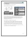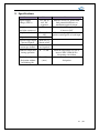
1
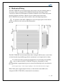
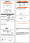
USER MANUAL
DLC-C2P6-D-E
LED CURRENT CONTROLLER
Revision 1
JM Vistec System Private Limited
10 Kaki Bukit Road 1
#01-40 KB Industrial Building
Singapore 416175
Tel : 65 67485517
Fax : 65 67485507
Web : www.jm-vistec.com
1 Disclaimer
Except as prohibited by law:
- All hardware, software and documentation is provided on an “as is” basis.
- It is essential that the user ensures that the operation of the product is suitable for
their application.
- The user must ensure that incorrect functioning of this equipment cannot cause
any dangerous situation or significant financial loss to occur.
- JM Vistec System Private Ltd will not accept any liability for consequential loss
of any kind.
2 Getting Started
Read the sections on Safety and Specifications and check the DLC-C2P6-D-E fulfils
your requirements.
Controlling DLC-C2P6-D-E is achieved through Ethernet communication to
Computer. Connect a straight Ethernet cable if a switch is installed or a cross Ethernet
cable directly to any computer Ethernet port.
Note that most new computer do come with auto-cross feature Ethernet which allow
straight or cross Ethernet to be able to communicate with controller directly with
Switch or hub.
Connect DLC-C2P6-D-E to a supply and an LED lighting unit as described in
Connections. Once DLC-C2P6-D-E powers up observe Ethernet port LED is lighted.
Users need refer to Ethernet Configuration and Ethernet Communications sections for
more in depth information.
Mount the DLC-C2P6-D-E as described in “Mechanical Fixing” using a DIN rail or
the mounting holes.
Read the section on Heat Dissipation. Set up the DLC-C2P6-D-E for the desired
operation and test.
2
/ 18
3 Safety
3.1 DLC-C2P6-D-E– Safety
Please read this before using DLC-C2P6-D-E. If in doubt, contact your distributor
Or JM Vistec
Where this symbol appears in the manual, refer to the text for precautions to be
taken.
3.2 Heat
The DLC-C2P6-D-E can get very hot. It should be positioned where personnel cannot
accidentally touch it and away from flammable materials.
Read the section on Heat Dissipation. Do not exceed the power ratings given in the
manual.
Note that at the maximum ratings the case temperature can reach above 65℃.
3.3 Electrical
The user must ensure that potential difference between any combinations of applied
signals does not exceed 48V.
WARNING: Higher voltages may cause a danger to personal health.
DLC-C2P6-D-E does not have complete tracking isolation of inputs and outputs.
Transients caused by inductive loads must be suppressed external to DLC-C2P6-D-E.
3.4 General
The DLC-C2P6-D-E must not be used in an application where its failure could cause
a danger to personal health or damage to other equipment.
If equipment is used in a manner not specified by the manufacturer, the protection
provided by equipment may be impaired.
3
/ 18
4 Mechanical Fixing
The DLC-C2P6-D-E can be mounted onto a flat surface using the mounting holes in
the corners, Refer to diagram. DLC-C2P6-D-E should only be mounted either
vertically or with its base horizontal. It should be mounted at least 15mm away from
the sides of plastic enclosures. Likewise leave a similar space between the
DLC-C2P6-D-E and any parts which could be affected by high temperatures.
The enclosure of the DLC-C2P6-D-E is used to dissipate power in the form of
heat. Refer to the section on Heat Dissipation.
The DLC-C2P6-D-E can be mounted from above using the M4 clearance corner holes,
or from beneath using the M4 tapped holes (maximum screw length inside is 6mm).
To avoid a fire hazard consider the implications of overheating in the unlikely
event of a fault in the DLC-C2P6-D-E. The power dissipation in a fault
condition is approximately given by sum of the following for the two channels:
(<Power supply voltage> - <rated voltage for lighting>) * <max current delivered by Power supply>
Either limits power supply output current(s) so that not more than 30W can be
dissipated in DLC-C2P6-D-E, or mount unit in an enclosure.
4
/ 18
Choose a PSU that limits its output current by design, by setting current limit on
power supply (if this feature exists) or use fuses. Remember to de rate the fuse, if
mounted in an enclosure, as temperature will be higher than ambient.
The DLC-C2P6-D-E enclosure is a fire enclosure as long as the following conditions
are met:
•
•
The Ethernet connector must not be facing downwards
The mounting holes on underside must be covered or have a screw fitted.
If an enclosure is used, enclosure should be metal or plastic (with a flammability
rating of UL94 V1 or better); with no holes below or to the sides of the
DLC-C2P6-D-E when mounted. Cable entries below DLC-C2P6-D-E should be via
glands that have a flammability rating as before. Observe specified gap between the
DLC-C2P6-D-E and any other part or side of the enclosure. DLC-C2P6-D-E does not
have an IP rating and should be mounted so that moisture and dirt cannot enter the
unit.
5
/ 18
5 Heat Dissipation
DLC-C2P6-D-E has a linear circuit to produce constant current output. This means
that it generates heat which needs to be dissipated.
5.1 Heat Output per Channel
For a continuous output current the heat output is given by:
<Heat output (W)> = <output current (A)> * (<supply voltage (V)> - <voltage across lighting (V)>)
Where:
Output current
Set by the user
Supply voltage
Voltage across PSU+ and PSUVoltage across lighting Voltage across LD1+ and LD1- (for channel 1)
This is usually easy to calculate as voltage across lighting is usually the voltage rating
of light given in its specification or can be measured using a voltmeter.
For a pulsed output the heat output is given by:
<Heat output (W)> = <output current (A)> * <duty cycle>
* (<supply voltage (V)> - <voltage across lighting when pulsing (V)>)
<Duty cycle> = <pulse width in seconds> * <trigger frequency in Hertz>
When overdriving, voltage across lighting is more difficult to find out. In most cases
it is reasonable to use voltage rating of the light.
5.2 Total Heat Output
The heat output for DLC-C2P6-D-E is given by adding heat output for both channels,
as calculated above. There are several ways to reduce heat output from
DLC-C2P6-D-E
:
• Use pulse mode. If the output is only on when you need it then you can
dramatically reduce heat output. Feed camera trigger into DLC-C2P6-D-E and
pulse lights.
• Turn light off when not needed. If you don't have precise timing of when camera
will trigger, you can use Switched mode to switch output off or on depending on
trigger input (or use DLC-C2P6-D-E with Ethernet commands to turn the output
on and off).
• Reduce the output current if possible
• Reduce the supply voltage. Most PSUs have some adjustment in their output
voltage.
• Connect lights in series instead of parallel. If you have an array of lights or LEDs
in parallel then changing arrangement to serial will increase voltage across them
6
/ 18
•
but reduce overall current.
Use two DLC-C2P6-D-E and use one channel from each. For high power
applications this may be the easiest solution. Even with one light, it is possible to
parallel up two output channels from different DLC-C2P6-D-E.
With no heat sinking and no airflow, DLC-C2P6-D-E can dissipate approximately the
following:
8W at 30℃ ambient
6W at 40℃ ambient
4W at 50℃ ambient
If heat output is no greater than these limits, then no heat sinking is required. If the
heat output is above but less than 24W then DLC-C2P6-D-E needs to be bolted to a
solid piece of metal to dissipate heat. Above 24W, it is necessary to have a large heat
sink with fan cooling
7
/ 18
6 Connections
The screw terminals have the following connections:
Opto-Coupled Trigger Input Details
Screw
Terminal ID
Operating Conditions
3V <= VTRIG <= 24V
VTRIG < 1V
VF
Logic 1
Logic 0
1.5V typ
TRIG1 TRIG1 +
LED1 +
LED1 PSU +
PSU LED2 LED2 +
TRIG2 +
TRIG2 -
Function
Channel 1 trigger input
- See illustration to left
Channel 1 output to
lighting
Power Supply +ve
Power Supply –ve ( GND )
Channel 2 output to
lighting
Channel 1 trigger input
- See illustration to left
Ensure wire gauge used for these connections is appropriate for current to be drawn.
Ideally, wires should be double crimped or independently secured to ensure they
cannot come loose. Route low voltage and mains wiring separately. If they must be
loomed together ensure that low voltage insulation rating is sufficient or that
supplementary insulation is used.
DLC-C2P6-D-E has a single power input connection.
Power supplies should be regulated with SELV compliant outputs (fault tolerant).
Consideration should be given to fusing PSU+. The fuse value can be based on
average current output. Note that in Europe fuses are designed to conduct at their
rated current, while in the USA fuses are designed to blow at their rated current.
RJ45 Ethernet connector requires a straight through cable to connect into a network
switch, hub or router. It runs at 10Mbits per second.
8
/ 18
7 General Description
The DLC-C2P6-D-E current controller provides repeatable intensity control of LED
lighting for machine vision applications. It includes intensity control, timing and
triggering functions required for machine vision systems.
LED lighting needs constant current supply as small variations in voltage can cause
large variations in light output. Currents can be specified in 2.5mA steps to give very
fine control of intensity.
Two modes of operation are provided separately for each channel:
- Continuous
In continuous mode, output is a continuous current.
- Pulse (Strobe)
In this mode output is pulsed once per trigger. One trigger input is used as a trigger.
Delay and pulse duration can range from 20us to 1 second in 20us steps.
- Switched
In switched mode a trigger input can be used to switch output current on and off.
Output is only enabled when the input has a voltage on it.
For Pulsed mode, either channel can be controlled by either trigger input.
DLC-C2P6-D-E can be set up using Ethernet commands. Configurations are saved ins
non-volatile memory, so DLC-C2P6-D-E will resume same operation after a power
cycle.
7.1 Output Modes
The trigger inputs are used as follows:
Mode
Trigger Input
Continuous Unused
Switched
Trigger Input at 0V
Pulsed
Trigger Input between 4.5V
and 24V
Rising edge
Goes from 0V to 4.5V above
Falling edge
Goes from 4.5V above to 0V
Output
Output is on
Output is off if P flag = 1 ( default )
Output is on if P flag = 0
Output is on if P flag = 1 ( default )
Output is off if P flag = 0
Pulse is triggered if P flag = 1 (default )
See RE Ethernet command
Pulse is triggered if P flag = 0
9
/ 18
7.1.1 Continuous Output and Switched Output
In continuous mode, output current is fixed and continuous. Switched mode uses a
trigger input to switch output on or off.
Both continuous and switched modes, output current can be varied from 0% to 100%
of full brightness.
7.1.2 Pulsed Output
Output is off by default. When DLC-C2P6-D-E is triggered it will wait for delay and
then pulse output. Delay, pulse width and pulse intensity are all configurable.
In pulsed mode, brightness can be set up to 999% of its rating, but only for short
periods and at low duty cycles, so that lighting does not overheat and get damaged.
The duty cycle is limited by ignoring triggers which are too soon after previous
trigger.
Output Brightness
0 to 100%
101% to 200%
201% to 300%
301% to 500%
501% to 999%
Allowed Pulse Width
2999ms
30ms
10ms
2ms
1ms
Allowed Duty Cycle
100%
30%
20%
10%
5%
So for example, if brightness is set to 350%, then DLC-C2P6-D-E will not allow
pulses greater than 2ms long. If trigger occurs within 20ms of a previous trigger (so
that the duty cycle would be greater than 10%) the trigger is ignored.
10
/ 18
8 Specifications
Parameter
Digital supply
voltage ( PSU+)
Supply current with
no lights connected
Input enable level
Input disable level
Typical trigger input
current required
Maximum output
current per channel
Ambient temperature
during operation
Total allowed power
dissipation without
heatsinking (PD)
Value
12V DC to
48V DC
regulated
150mA
From 4.5 to
24V
< 1V
3mA at 4.5V,
22mA at 24V
2A continuous
or 6A pulsed
5
50
℃ to ℃
PD = 8 Watts
( max )
Notes
Must be at least 1V greater than
load potential difference at
maximum required current
This is with a 12V supply. Current
is lower at 24V
This is voltage applied between
positive and negative of each input
Ambient temperature need to be
lower if DLC-C2P6-D-E is
dissipating a lot of heat
See Section for information on heat
dissipation
11
/ 18
9 Ethernet Configurations
9.1 Communication
DLC-C2P6-D-E can be configured via the Ethernet connection using UDP or TCP/IP.
A Configuration Program with source code is given free of charge.
Communication consists of commands sent by the host (controlling PC). All output
generated by command is returned in reply UDP or TCP/IP packets. The last character
sent is “>” (“greater than” symbol). Once this is received, host knows that command
has been completed.
It is recommended that host waits for the “>” symbol before sending next command.
UDP communications are not guaranteed to arrive, so host software must be able to
cope with lost messages.
Using the GT command, a host can request that a message is sent to it whenever an
error occurs.
For TCP and UDP, commands from a host should be sent to destination port 30313.
Replies will be to destination port 30312.
A TCP/IP connection will timeout and close if it is idle for more than 10 seconds. Host
must send regular “heartbeat” commands (eg “VR”) to keep the link open.
9.2 Command Structure
Several commands can be put into one command line by separating them by a
semi-colon (“;”). A carriage return character should be sent to terminate command line.
DC-C2P6-D-E will send any replies to the commands and then send a ‘>’ character to
indicate that the command line has been completed.
Commands comprise a code of two letters followed by the parameters (if any) needed
for command. Spaces in commands are ignored.
Numeric parameters are separated by a comma (“,”). For a parameter which is a time
period default units are milliseconds. “s”, “ms” or “us” can be added to the end of the
number to indicate seconds, milliseconds or microseconds. For current setting, “a” or
“ma” can be added to indicate “amps” or milliamps”. The default is amps.
12
/ 18
For example:
Parameter
0.1
200us
0.1s
100ma
2.45A
2.3
Meaning
0.1 milliseconds
200 microseconds
0.1 seconds
100mA
2.45A
2300mA or 2.3A
Note that parameters are in “USA/UK” format so that a half is written “0.5” not
“0,5”
Command codes and their meaning are described below. Upper case commands are
shown, followed by lower case letters denoting the numeric argument.
Error number
Reason
Err 1
A parameter value is invalid
Err 2
Command not recognised
Err 3
Numeric value is wrong format
Err 4
Wrong number of parameters
Err 5
(Warning only) A timing parameter was
out of range and has been adjusted.
Any changes made using Ethernet commands are not saved permanently until the
AW command has been issued.
9.3.1 General Commands
Save the settings to memory.
AW
Once the settings are saved to memory they are then retained when the unit is switched off. If
this is not done, changes to the settings are volatile, and if the unit is switched off they revert to
those in force when the last AW command was issued.
13
/ 18
Report the configuration
ST
Typical output is:
CH 1, MD 2, IP 4, CS 0.100A, SE 75.0, DL 2.0us, PU 300.0us, RT 500.0us, FL 1
CH 2, MD 0, IP 2, CS 0.100A, SE 25.8, DL 1.000ms, PU 1.000ms, RT 0.0us, FL 0
Where the numeric values are:
CH
Channel number
MD
Mode: 0 = continuous, 1 = pulse, 2 = switched
IP
Trigger input: 1, 2, 3, 4
CS
Current rating of the light
SE
Brightness percentage setting
DL
Pulse delay
PU
RT
Pulse width
Retrigger delay
ST0
Report general settings. Typical output is:
TM 1, TP 20.00ms
STc
Where c channel number (1 or 2)
Report settings for a single channel.
Enable Ethernet Messages
GTm
m
= 0 to disable Ethernet messages
= 1 to enable Ethernet messages
When Ethernet messages are enabled, any error reports are sent to the most recent UDP
or TCP address from which a command has been received.
Messages are of the form:
Evtc,e
Where c zero for no channel or channel number (1 or 2)
v event value:
32 to 47
Lighting error code
128
Light detected and waiting for current rating
129
Light detected and not waiting for current rating
Clear any Errors
GR
If Ethernet messages are not enabled, last event or error number can be read by this
command. Any error displayed on the unit is cleared, so if there was a lighting error,
DLC-C2P6-D-E will resume auto-sensing on that channel.
The reply will be in he same form as the GT command above. If there are no
outstanding events or errors, then only the prompt “>” is returned.
14
/ 18
Clear Settings
CL
Clears output channel configuration. This excludes Ethernet settings. For each channel,
if AUTO_SENSE flag is set, then the flag and current rating are preserved.
Set/Clear the Webpage Password
EY
EY asc1, asc2, asc3, asc4, asc5, asc6
This command sets password required to access web pages. If EY is entered on its own
then password is cleared. There are six optional parameters, which are ASCII values for
password from one to six letters. A value of 65 is ‘A’, 66 is ‘B’, etc to 90 is ‘Z’.
Set the Channel Flags
REc,m
Where:
c = output channel (1, 2, 3, 4)
m = Flags, where
bit 0
1 = No autosense (current rating is fixed)
0 = Autosense (current rating needs to be entered on connection)
bit 1
1 = No error detect
0 = Error detect. The PP420 continually monitors output current
and voltage
bit 2
1 = Negative trigger. In pulse mode the trigger is the falling edge.
In switched mode a low input turns the light on.
0 = Positive trigger. In pulse mode the trigger is the leading edge.
In switched mode a high input turns the light on.
Set the trigger input
This command changes which input is used when in switched or pulsed modes.
RPc,t
Where:
c = output channel (1, 2, 3, 4)
t = trigger input (1, 2, 3, 4)
Set the output current rating
This command changes the current rating for a light.
RRc,v
Where:
c = output channel (1, 2, 3, 4)
v = rated current (10mA to 2A)
15
/ 18
Set continuous mode
The output is set to continuous mode at a percentage of full brightness.
RSc,s
Where:
c = output channel (1, 2, 3, 4)
s = setting in percent (s = 0 to 100)
Set switched mode
The output is set to switched mode at a percentage of full brightness.
RWc,s
Where:
c = output channel (1, 2, 3, 4)
s = setting in percent (s = 0 to 100)
Set pulse mode
Output can be set up to pulse on a trigger input. Delay from trigger to start of pulse,
length of the pulse and brightness are configurable.
An error is generated if the brightness setting requires a current greater than 10A or if
the combination of pulse width and setting is not allowed.
RTc,p,d,s
RTc,p,d,s,r
Where:
c = output channel (1, 2, 3, 4)
p = pulse width in milliseconds (0.02 to 999)
d = delay from trigger to pulse in milliseconds (0.02 to 999)
s = setting in percent (s = 0 to 999)
r = retrigger delay. This parameter is optional
Simulate an Input Trigger
TRc
c which input channel (1, 2, 3, 4)
Simulates a trigger pulse. If channel is in pulse mode it will pulse.
Set Internal Trigger
Enable or disable internal trigger. When enabled, all outputs are triggered
simultaneously using an internal trigger signal. This setting can be saved to non-volatile
memory using AW command.
TT0
Disable internal trigger
TT1
Enable internal trigger (uses previously set period)
TT1,p
Enable internal trigger and set the period
Where:
p= period of the triggers in microseconds
16
/ 18
For example:
TT1,200 Set the internal trigger to 200ms (5Hz)
TT1,500US Set the internal trigger to 500us (2KHz)
9.3.2 Command Summary
Command
AW
ST
GT
GR
VR
RR
RS
RW
RT
Example
AW
ST
GT1
GR
VR
RR1,0.2
RS1,65
RW1,50
RT2,3,4,50
TT
TR
CL
EY
RP
RE
TT1,1ms
TR2
CL
EY80,87
RP2,1
RE1,3
Effect
Save changes
Show configuration
Enable Ethernet messages
Get any error codes
Read firmware version
Set rating of channel 1 to 0.2A
Set channel 2 to 65% brightness continuous
Set channel 1 to 50%, switch by Trig 1
Set channel 2 to 3ms pulses, delay by 4 ms, at 50%
brightness
Set internal triggers every 1 ms
Simulate trigger on trigger input 2
Clear all settings, except Ethernet
Set webpage password to “PW”
Use trigger input 1 for Channel 2
Set channel 1 to ignore lighting errors and do not prompt
for current rating of a light when it is connected
17
/ 18
If Ethernet message are enabled, these errors cause a message to be sent of the form:
Err c,e
Where: c = output channel (1, 2)
e = error number
9.3.3 Error Code Summary
Error number
Err 1
Err 2
Err 3
Err 4
Err 5
Reason
A parameter value is invalid
Command not recognized
Numeric value is wrong format
Wrong number of parameters
One of parameters is out of range. The value of the parameter has
been adjusted. For example, sending an RT command with a delay
of 0 will get a reply of “Err 5”. When settings are viewed delay will
have been set to 20us.
Err 8, 12
EEPROM corrupt. Configuration has been cleared.
Err 20
Can’t save settings to EEPROM.
Err 27
Can’t read Ethernet settings from EEPROM, so these maybe
incorrect.
Err 34
Internal power dissipation is too high. Output turned off
Err 35
Output current to lighting is too low
Err 36
Output is short circuit
Err 37
Voltage required for lighting has increased too much. Check for
aging of lighting or a failed LED
Err 38
Voltage required for lighting has decreased too much. Check for
aging of lighting or a failed LED
Err 39
There is not enough supply voltage for requested output current
Err 40, 41, 45
More current is being output than should be, so DLC-C2P6-D-E
has turned off outputs. This may be caused by hardware error.
Check with your distributor.
Err 42
Output current is too high
Err 44
Temperature error. DLC-C2P6-D-E is too hot and has switched off
to protect itself
Any other errors are internal errors.
18
/ 18