1
An
Company
ZEPIR0AAS02MODG
ZMOTION™ Detection Module
Product Specification
PS028405-1010
Copyright ©2010 by Zilog, Inc. All rights reserved.
www.zilog.com
ZMOTION™ Detection Module
Product Specification
Warning: DO NOT USE IN LIFE SUPPORT
LIFE SUPPORT POLICY
ZILOG'S PRODUCTS ARE NOT AUTHORIZED FOR USE AS CRITICAL COMPONENTS IN LIFE
SUPPORT DEVICES OR SYSTEMS WITHOUT THE EXPRESS PRIOR WRITTEN APPROVAL OF
THE PRESIDENT AND GENERAL COUNSEL OF ZILOG CORPORATION.
As used herein
Life support devices or systems are devices which (a) are intended for surgical implant into the body, or (b)
support or sustain life and whose failure to perform when properly used in accordance with instructions for
use provided in the labeling can be reasonably expected to result in a significant injury to the user. A
critical component is any component in a life support device or system whose failure to perform can be
reasonably expected to cause the failure of the life support device or system or to affect its safety or
effectiveness.
Document Disclaimer
©2010 by Zilog, Inc All rights reserved. Information in this publication concerning the devices,
applications, or technology described is intended to suggest possible uses and may be superseded. ZILOG,
INC. DOES NOT ASSUME LIABILITY FOR OR PROVIDE A REPRESENTATION OF ACCURACY
OF THE INFORMATION, DEVICES, OR TECHNOLOGY DESCRIBED IN THIS DOCUMENT.
Z I L O G A L S O D O E S N O T A S S U M E L I A B I L I T Y F O R I N T E L L E C T U A L P R O P E RT Y
INFRINGEMENT RELATED IN ANY MANNER TO USE OF INFORMATION, DEVICES, OR
TECHNOLOGY DESCRIBED HEREIN OR OTHERWISE. The information contained within this
document has been verified according to the general principles of electrical and mechanical engineering.
ZMOTION and Z8 Encore! XP are trademarks or registered trademarks of Zilog, Inc. (An IXSYS
Company). All other product or service names are the property of their respective owners.
PS028405-1010
ZMOTION™ Detection Module
Product Specification
iii
Revision History
Each instance in the revision history table reflects a change to this document from
its previous revision. For more details, refer to the corresponding pages or appropriate links given in the table below.
Date
Revision Level Description
Page Number
October 2010
05
Replaced all instances of ePIR with
advanced passive infrared.
All
September
2010
04
Fixed formatting and pagination
issues.
All
September
2010
03
Replaced Zilog logos, ePIR with
ZMOTION, and Zdots with Module.
Updated Figure 11.
All
October 2008
02
Updated Related Documents section
All
(changed 88-pin SOIC to 28-pin SOIC
for Z8FS040AHJ20SG). Removed
references to GP and General
Purpose.
October 2008
PS028405-1010
01
Original issue
All
Revision History
ZMOTION™ Detection Module
Product Specification
iv
Table of Contents
Revision History . . . . . . . . . . . . . . . . . . . . . . . . . . . . . . . . . . . . . . . . . . . . . . . . iii
Table of Contents . . . . . . . . . . . . . . . . . . . . . . . . . . . . . . . . . . . . . . . . . . . . . . . iv
Architectural Overview . . . . . . . . . . . . . . . . . . . . . . . . . . . . . . . . . . . . . . . . . . . 1
Features . . . . . . . . . . . . . . . . . . . . . . . . . . . . . . . . . . . . . . . . . . . . . . . . . . . . 1
ZEPIR0AAS02MODG Block Diagram . . . . . . . . . . . . . . . . . . . . . . . . . . . . . . 2
Pin Description . . . . . . . . . . . . . . . . . . . . . . . . . . . . . . . . . . . . . . . . . . . . . . . 3
Operational Modes . . . . . . . . . . . . . . . . . . . . . . . . . . . . . . . . . . . . . . . . . . . . 3
Setting Operation Mode . . . . . . . . . . . . . . . . . . . . . . . . . . . . . . . . . . . . . . 4
Signal Descriptions (Hardware Interface Mode) . . . . . . . . . . . . . . . . . . . . . . 4
GND - Ground - Pin 1 and Pin 8 . . . . . . . . . . . . . . . . . . . . . . . . . . . . . . . 4
VDD - Supply Voltage - Pin 2 . . . . . . . . . . . . . . . . . . . . . . . . . . . . . . . . . 4
RXD/DLY - Delay - Pin 3 . . . . . . . . . . . . . . . . . . . . . . . . . . . . . . . . . . . . . 4
TXD/SNS - Sensitivity - Pin 4 . . . . . . . . . . . . . . . . . . . . . . . . . . . . . . . . . 5
/MD - Motion Detect - Pin 5 . . . . . . . . . . . . . . . . . . . . . . . . . . . . . . . . . . . 5
LG - Light Gate - Pin 6 . . . . . . . . . . . . . . . . . . . . . . . . . . . . . . . . . . . . . . . 6
/SLP - SLEEP Mode - Pin 7 . . . . . . . . . . . . . . . . . . . . . . . . . . . . . . . . . . . 6
Signal Descriptions (Serial Interface Mode) . . . . . . . . . . . . . . . . . . . . . . . . . 6
GND - Ground - Pin 1 and Pin 8 . . . . . . . . . . . . . . . . . . . . . . . . . . . . . . . 6
VDD - Supply Voltage - Pin 2 . . . . . . . . . . . . . . . . . . . . . . . . . . . . . . . . . 6
RXD/DLY - Receive Data - Pin 3 . . . . . . . . . . . . . . . . . . . . . . . . . . . . . . . 6
TXD/SNS - Transmit Data - Pin 4 . . . . . . . . . . . . . . . . . . . . . . . . . . . . . . 7
/MD//RST - Motion Detect and Reset - Pin 5 . . . . . . . . . . . . . . . . . . . . . . 7
LG - Light Gate - Pin 6 . . . . . . . . . . . . . . . . . . . . . . . . . . . . . . . . . . . . . . . 7
/SLP - SLEEP Mode - Pin 7 . . . . . . . . . . . . . . . . . . . . . . . . . . . . . . . . . . . 7
Voltage Brownout Protection and Power-On-Reset . . . . . . . . . . . . . . . . . . . 8
Operation . . . . . . . . . . . . . . . . . . . . . . . . . . . . . . . . . . . . . . . . . . . . . . . . . . . . 9
Hardware Interface Mode . . . . . . . . . . . . . . . . . . . . . . . . . . . . . . . . . . . . . . . 9
SLEEP Mode in Hardware Interface Mode . . . . . . . . . . . . . . . . . . . . . . 10
Serial Interface Mode . . . . . . . . . . . . . . . . . . . . . . . . . . . . . . . . . . . . . . . . . 10
SLEEP Mode in Serial Interface Mode . . . . . . . . . . . . . . . . . . . . . . . . . 11
Serial Interface Commands and Description . . . . . . . . . . . . . . . . . . . . . 11
Serial Commands . . . . . . . . . . . . . . . . . . . . . . . . . . . . . . . . . . . . . . . . . . . . 15
PS028405-1010
Table of Contents
ZMOTION™ Detection Module
Product Specification
v
Motion Status . . . . . . . . . . . . . . . . . . . . . . . . . . . . . . . . . . . . . . . . . . . . .
Light Gate Level . . . . . . . . . . . . . . . . . . . . . . . . . . . . . . . . . . . . . . . . . .
/MD/RST Pin Configuration . . . . . . . . . . . . . . . . . . . . . . . . . . . . . . . . . .
/MD Activation Time . . . . . . . . . . . . . . . . . . . . . . . . . . . . . . . . . . . . . . .
Hyper Sense . . . . . . . . . . . . . . . . . . . . . . . . . . . . . . . . . . . . . . . . . . . . .
Frequency Response Setting . . . . . . . . . . . . . . . . . . . . . . . . . . . . . . . .
Motion Detection Suspend . . . . . . . . . . . . . . . . . . . . . . . . . . . . . . . . . .
Software Revision . . . . . . . . . . . . . . . . . . . . . . . . . . . . . . . . . . . . . . . . .
Serial Interface Command Mode . . . . . . . . . . . . . . . . . . . . . . . . . . . . . .
Motion Detected Unsolicited Mode . . . . . . . . . . . . . . . . . . . . . . . . . . . .
/MD Current Active Output Time . . . . . . . . . . . . . . . . . . . . . . . . . . . . . .
Ping . . . . . . . . . . . . . . . . . . . . . . . . . . . . . . . . . . . . . . . . . . . . . . . . . . . .
Range Setting . . . . . . . . . . . . . . . . . . . . . . . . . . . . . . . . . . . . . . . . . . . .
Sensitivity . . . . . . . . . . . . . . . . . . . . . . . . . . . . . . . . . . . . . . . . . . . . . . .
Directional Detection . . . . . . . . . . . . . . . . . . . . . . . . . . . . . . . . . . . . . . .
Module Reset . . . . . . . . . . . . . . . . . . . . . . . . . . . . . . . . . . . . . . . . . . . .
Sleep Mode . . . . . . . . . . . . . . . . . . . . . . . . . . . . . . . . . . . . . . . . . . . . . .
Detection Pattern . . . . . . . . . . . . . . . . . . . . . . . . . . . . . . . . . . . . . . . . . . . . .
Mechanical Information . . . . . . . . . . . . . . . . . . . . . . . . . . . . . . . . . . . . . . . .
ZMOTION™ Detection Module Schematic . . . . . . . . . . . . . . . . . . . . . . . . .
Related Documents . . . . . . . . . . . . . . . . . . . . . . . . . . . . . . . . . . . . . . . . . . .
Related Products . . . . . . . . . . . . . . . . . . . . . . . . . . . . . . . . . . . . . . . . . . . . .
15
16
18
20
22
24
26
28
29
31
33
34
36
37
38
42
44
45
46
47
48
48
Electrical Characteristics . . . . . . . . . . . . . . . . . . . . . . . . . . . . . . . . . . . . . . . . 49
Absolute Maximum Ratings . . . . . . . . . . . . . . . . . . . . . . . . . . . . . . . . . . 50
Ordering Information . . . . . . . . . . . . . . . . . . . . . . . . . . . . . . . . . . . . . . . . . . . 51
Part Numbers . . . . . . . . . . . . . . . . . . . . . . . . . . . . . . . . . . . . . . . . . . . . 51
Customer Support . . . . . . . . . . . . . . . . . . . . . . . . . . . . . . . . . . . . . . . . . . . . . . 55
PS028405-1010
Table of Contents
ZMOTION™ Detection Module
Product Specification
1
Chapter 1 Architectural Overview
Zilog’s ZMOTION™ Detection Module is a complete and fully functional motion detection solution ideal for lighting control and other occupancy and proximity detection applications. It is a board level module that combines the unique features of Zilog's Z8FS040
Motion Detection Microcontroller with a Pyroelectric Sensor and a low profile Fresnel
lens.
The surface mount pyroelectric sensor and Fresnel lens combine to provide the lowest
possible profile without sacrificing performance. The module is only 25.5 mm x 16.7 mm
(a little over ½ square inch) so it can easily fit into many size constrained applications.
The ZMOTION™ Detection Module can operate in a simple Hardware mode which provides an output signal when motion is detected; or in an advanced asynchronous serial
mode when greater control over the motion detection performance is required. In both
modes sensitivity and delay time can be controlled to match the application requirements.
It is an excellent choice for lighting controls, access control, display systems, and general
purpose proximity sensing. It is also an easy way to add energy management capability to
various applications such as vending machines and appliances; and Zilog's Evaluation Kit
makes it quick and easy to integrate into your own custom application.
Features
Key features of the ZMOTION™ Detection Module include:
•
•
•
•
•
•
•
•
•
•
•
•
•
•
PS028405-1010
Complete, fully functional motion detection including Fresnel lens
– Comes pre-programmed with motion detection software
Small form factor—25.5 mm x 16.7 mm
Up to 5 m x 5 m, 60 degree detection pattern.
Sensitivity control via simple hardware configuration
Advanced serial (UART) based configuration and interface
SLEEP mode for low power applications
No temperature compensation required
Input to support CDS photocell input for ambient light detection
Minimal components ensure highest possible Mean Time Between Failures (MTBF)
Application code can also be modified to support custom solutions
Complete development system available
Operates from 2.7 V to 3.6 V power supply
Simple 8-pin interface
Standard operating temperature: 0 °C to 70 °C
Architectural Overview
ZMOTION™ Detection Module
Product Specification
2
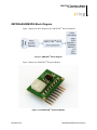
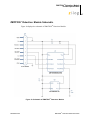
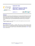
ZEPIR0AAS02MODG Block Diagram
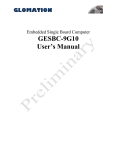
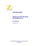
Figure 1 displays the block diagram of the ZMOTION™ Detection Module.
Figure 1. ZMOTION™ Block Diagram
Figure 2 displays the ZMOTION™ Detection Module.
Figure 2. The ZMOTION™ Detection Module
PS028405-1010
ZEPIR0AAS02MODG Block Diagram
ZMOTION™ Detection Module
Product Specification
3
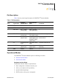
Pin Description
Table 1 lists the pin and signal description for ZMOTION™ Detection Module.
Table 1. Pin Description
Pin#
Signal Name
Hardware
Interface Mode
Serial Interface
Mode
Comments
1
GND
Ground
Ground
—
2
VDD
Supply Voltage
Supply Voltage
—
3
RXD / DLY
DLY — Delay
(analog input)
RXD — Receive
Data (digital input)
—
4
TXD / SNS
SNS — Sensitivity TXD — Transmit
Mode Select during reset
(analog input)
Data (digital output)
5
/MD/RST
Motion Detect
(digital output)
6
LG
Light Gate(analog Light Gate (analog
input)
input)
If unused, connect to Vdd
7
/SLP/DBG
/SLP — Sleep
(digital input)
/SLP — Sleep
(digital input)
DBG is used for programming
and debug
8
GND
Ground
Ground
—
Configurable: /RST - Default is /RST (Reset) in Serial
Reset (digital input) / Interface Mode
MD Motion Detect
(digital input)
Operational Modes
The ZMOTION™ Detection Module operates in following two modes:
•
•
Hardware Interface Mode
Serial Interface Mode
Hardware Interface Mode
The Hardware Interface Mode is explained below:
•
•
•
•
PS028405-1010
Basic configuration via hardware interface pins
Allows you to adjust sensitivity and delay
Optional ambient light input
SLEEP mode to reduce power consumption
Pin Description
ZMOTION™ Detection Module
Product Specification
4
Serial Interface Mode
The Serial Interface Mode is explained below:
•
•
•
Advanced configuration and status via serial interface
/MD, LG and /SLP remain functional
The serial interface runs at: 9600 bps, no parity, 8 data bits, and 1 stop bit, no flow
control
Setting Operation Mode
Serial Interface Mode Selection
To select Serial Interface Mode, provide a pull up resistor from TXD/SNS to Vdd during
power ON or when exiting SLEEP Mode (typically 100 K). The device detects that the
voltage on the pin is greater than 2.5 V and enables the TXD and RXD signals. /MD, LG
and /SLP remain active also. This resistor will have no effect on the transmitted data.
Hardware Interface Mode Selection
The Hardware Interface Mode is selected when TXD/SNS is between 0 V and 1.8 V during power ON or when exiting SLEEP Mode.
For examples of using the ZMOTION™ Detection Module in Hardware and Serial Interface Modes, see Appendix A—Hardware Interface Mode on page 52 and Appendix
B—Serial Interface Mode on page 53.
Signal Descriptions (Hardware Interface Mode)
GND - Ground - Pin 1 and Pin 8
Both Pin 1 and Pin 8 ground signals are tied together on the ZMOTION™ Detection Module PCB and are connected to power ground.
VDD - Supply Voltage - Pin 2
Provides power to the ZMOTION™ Detection Module. For power consumption, see
Electrical Characteristics on page 49.
RXD/DLY - Delay - Pin 3
A high impedance analog input pin that sets the time for the /MD (Motion Detect) pin to
remain active once motion has been detected. Provide a voltage between 0 and 2 V to
PS028405-1010
Signal Descriptions (Hardware Interface Mode)
ZMOTION™ Detection Module
Product Specification
5
select a delay of 2 seconds to 15 minutes (see Table 2). Typically a simple resistor divider
or trim pot is used to set the voltage.
Table 2. Delay Time and Voltage on DLY
Delay Time
Voltage on DLY
2 sec
0V
5 sec
0.2 V
10 sec
0.4 V
30 sec
0.6 V
1 min
0.8 V
2 min
1.0 V
3 min
1.2 V
5 min
1.4 V
10 min
1.6 V
15 min
1.8 V
TXD/SNS - Sensitivity - Pin 4
A high impedance analog input that sets the Module's sensitivity to motion. Provide a voltage between 0 V and 1.8 V to adjust the sensitivity to meet the application requirements. A
lower voltage means higher sensitivity. Typically a simple resistor divider or trim pot is
used to set the voltage.
1.8 V = Lowest Sensitivity
0 V = Highest sensitivity
This signal also determines the interface mode of the Module. At power ON and when
exiting SLEEP Mode, the signal is sampled and if it is greater than 2.5 V (for example,
pulled to VDD via resistor), then Serial Interface Mode is entered and the pin is converted
to TXD. If the signal is between 0 V and 1.8 V, Hardware Interface Mode is selected.
/MD - Motion Detect - Pin 5
An active Low output that is activated when motion is detected. The time that this signal
remains active is set by the DLY signal. This signal is actively driven High.
0 = Motion detected
1 = No motion detected
PS028405-1010
Signal Descriptions (Hardware Interface Mode)
ZMOTION™ Detection Module
Product Specification
6
LG - Light Gate - Pin 6
A high impedance analog input. This pin should be provided with a voltage that is proportional to the amount of ambient light in the environment (typically provided via a CDS
photo cell or similar circuit). The signal is used internally to gate the /MD output signal
such that it does not activate in the presence of daytime ambient light. When the voltage
on this pin is lower than 1.0 V, the /MD signal will not activate even when motion is
detected. If /MD is in an active state when LG transitions below 1.0 V, the current DLY
time is completed before /MD is deactivated. If LG is unused, connect to Vdd.
GND to 1.0 V = /MD is activated when motion is detected
1.0 V to Vdd = /MD does not activate when motion is detected
/SLP - SLEEP Mode - Pin 7
An active Low digital input. When at logic ‘0’, the Module enters low power SLEEP
mode. The Module does not detect any motion and /MD is driven inactive. When SLP is at
logic ‘1’, the Module exits SLEEP mode and begins detecting motion. This signal must be
held at logic ‘1’ during power ON.
0 = Module disabled - low power SLEEP mode is active
1 = Normal operation
Signal Descriptions (Serial Interface Mode)
GND - Ground - Pin 1 and Pin 8
Both Pin 1 and Pin 8 ground signals are tied together on the ZMOTION™ Detection Module Single Board Computer PCB and are connected to power ground.
VDD - Supply Voltage - Pin 2
This provides power to the Module. For power consumption, see Electrical Characteristics
on page 49.
RXD/DLY - Receive Data - Pin 3
This input is the asynchronous serial input used for sending commands and configuration
to the Module. It operates at 9600 bps, No Parity, 8 Data Bits, and 1 Stop Bit, no flow control. For a list and description of the commands supported, see Table 3.
PS028405-1010
Signal Descriptions (Serial Interface Mode)
ZMOTION™ Detection Module
Product Specification
7
TXD/SNS - Transmit Data - Pin 4
This output is the asynchronous serial data output from the Module in response to commands and configuration supplied on the RXD line. It operates at 9600 bps, No Parity, 8
Data Bits, 1 Stop Bit. For more information on the serial command interface, see Serial
Interface Commands and Description on page 11.
This signal also determines the interface mode of the Module. At power ON and when
exiting Sleep Mode, the signal is sampled and if it is higher than 2.5 V (for example,
pulled to VDD via resistor), then Serial Interface Mode is entered. If the signal is at a
value between 0 V and 1.8 V, Hardware Interface Mode is selected.
/MD//RST - Motion Detect and Reset - Pin 5
An active Low output that is activated when motion is detected. The time that this signal
remains active is set by the DLY signal. This signal is actively driven High.
0 = Motion detected
1 = No motion detected
As /RST, this pin provides an active low hardware reset signal for the Module. The function of this pin is selected by the ‘C’ serial command. The default value for this pin is
/RST.
LG - Light Gate - Pin 6
A high impedance analog input. The signal is used internally to gate the /MD signal such
that it does not activate in the presence of daytime ambient light. The voltage applied to
this pin should be proportional to the amount of ambient light in the environment (typically provided via a CDS photo cell or similar circuit).
•
•
LG > Light Gate Threshold Register - /MD is activated when motion is detected
LG < Light Gate Threshold Register - /MD does not activate when motion is detected
If /MD is in an active state when LG transitions above the programmed value, the current
DLY time is completed before /MD is deactivated.
If LG is unused, connect to Vdd.
/SLP - SLEEP Mode - Pin 7
An active Low digital input. When at logic '0' the Module enters low power SLEEP mode.
The Module does not detect any motion and /MD is driven inactive. When SLP is at logic
'1' the Module exits SLEEP mode and begins detecting motion. This signal must be held at
logic '1' during power ON.
PS028405-1010
Signal Descriptions (Serial Interface Mode)
ZMOTION™ Detection Module
Product Specification
8
0 = Module disabled - low power SLEEP mode is active
1 = Normal operation
Voltage Brownout Protection and Power-On-Reset
The ZMOTION™ Detection Module contains an internal Reset Controller with a Poweron Reset circuit and Brown out Protection to ensure proper operation. When power is first
applied, the POR circuit monitors the supply voltage and holds the Module’s MCU in the
Reset state until the supply voltage reaches a safe operating level. After the supply voltage
exceeds the POR voltage threshold (VPOR), the MCU is released and the Module begins
operating. A further delay of typically 20 seconds is included to allow the pyro-electric
sensor to stabilize. This value varies depending on environmental conditions. After this
delay, the system begins to look for motion. Prior to this delay, the /MD signal remains
inactive.
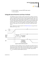
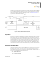
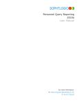
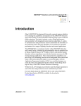
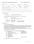
Figure 3 displays Power-on Reset operation. See Related Documents on page 48 for the
POR threshold voltage (VPOR).
Figure 3. Power-On Reset Operation
The ZMOTION™ Detection Module provides low Voltage Brownout (VBO) protection to
ensure proper operation when the supply voltage drops below an unsafe level - below the
VBO threshold voltage The VBO circuit senses this condition and forces the Module into
the Reset state. While the supply voltage remains below the POR voltage threshold
(VPOR), the VBO block holds the Module in the Reset.
PS028405-1010
Voltage Brownout Protection and Power-On-Reset
ZMOTION™ Detection Module
Product Specification
9
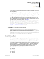
After the supply voltage again exceeds the Power-On Reset voltage threshold, the Module
progresses through a full Power-On Reset sequence, as described in the Power-On Reset
section. Figure 4 displays the Voltage Brownout operation. See Related Documents on
page 48 for the VBO threshold voltage (VVBO).
Figure 4. Voltage Brownout Reset Operation
Operation
When power is applied, the TXD/SNS pin is sampled to determine the mode of operation.
If the signal is above 2.5 V, serial interface mode is entered. If the signal is between 0 V
and 1.8 V hardware interface mode is entered. During this time, the pyro-electric sensor is
monitored and the device waits for it to become ready. Once it is stable, the device starts
normal operation in the selected mode. In hardware interface mode, the DLY, SNS, LG
and /SLP signals are sampled regularly. In serial interface mode, TXD/RXD are used to
communicate with the device and LG, /SLP and /MD also provide their defined functions.
Hardware Interface Mode
This mode of operation is selected when the SNS pin is at a value between 0 V and 1.8 V
during power ON (or after a reset caused by Vbo). Once Hardware Interface mode has
been established, this pin becomes the sensitivity input and accepts a voltage between 0 V
and 1.8 V to set the motion detection sensitivity level.
0 V = Highest Sensitivity
1.8 V = Lowest Sensitivity
PS028405-1010
Operation
ZMOTION™ Detection Module
Product Specification
10
These sensitivity levels are normally achieved with a simple resistor divider or potentiometer resistor divider.
After application of power, the PIR sensor is allowed to stabilize. At this point the MCU
waits for the PIR sensor to stabilize - this typically takes 20 seconds, but varies depending
on environmental conditions. The software dynamically monitors the pyro-electric sensor
during power up and begins detecting motion as soon as the sensor is stable.
The /MD (Motion Detect) pin is driven active (Low) when motion is detected. The time
that the signal remains active is determined by the voltage on the delay pin and can be set
to a value between 2 seconds and 15 minutes. See Table 2.
The Light Gate signal acts as a disable (gate) for the /MD signal. In a typical application,
this signal is a representation of the ambient light in the environment. If there is light
detected, the /MD signal does not activate even in the presence of motion. For an example
showing how to use the ZMOTION™ Detection Module in Hardware Interface Mode, see
Appendix A—Hardware Interface Mode on page 52.
SLEEP Mode in Hardware Interface Mode
In applications where motion detection is not always required, the Sleep signal can be
used to put the device into a low power mode. The advantage of this feature vs. removing
power from the Module is that the PIR stabilization time is much shorter.
If the Sleep (/SLP) input signal is driven Low, the device enters a low power SLEEP mode
and is woken up by deactivating the signal (driving the signal high).
Serial Interface Mode
The Serial Interface mode is implemented as a superset of the features available in Hardware interface mode. The interfacing device (Host) has an expanded feature set and more
flexibility with many of those features. The interface is designed to be simple to implement on the host processor and use as few resources as possible.
This mode of operation is selected when the SNS pin is above 2.5 V during power ON (or
after a reset caused by Vbo). Typically this signal is tied to Vdd through a pull-up resistor.
Once Serial Interface mode has been established, this pin becomes the Transmit Data
(TXD) output and is used to send responses to commands given to the device.
The serial interface is asynchronous and is set to:
•
•
•
•
PS028405-1010
9600 Baud
No Parity
8 Data Bits
1 Stop Bit
Serial Interface Mode
ZMOTION™ Detection Module
Product Specification
11
•
No flow control
In Serial Interface Mode, commands are sent to the device over the RXD input pin and
responses are sent from the device over the TXD output pin. The other signals on the
device (/MD, LG, /SLP) remain active in Serial Interface mode.
Motion Detect (/MD) output is driven active for the time set by the Output Activation
Time command when motion is detected. The signal is also gated by the (Light Gate) LG
input. For an example showing how to use the ZMOTION™ Detection Module in Serial
Interface Mode, see Appendix A—Hardware Interface Mode on page 52.
SLEEP Mode in Serial Interface Mode
In applications where motion detection is not always required, the Sleep signal can be
used to put the device into a low power mode. The advantage of this feature vs. removing
power from the Module is that the PIR stabilization time is much shorter.
If the Sleep (/SLP) input signal is driven Low, the device enters a low power SLEEP mode
and is woken up by either deactivating the signal (driving the signal high) or sending a
character over the serial interface - the character is received and processed.
Serial Interface Commands and Description
The Serial Interface operates as a Host-Client relationship where the Module is the client.
Commands are sent from the Host and the Module responds with the requested information or confirmation. The only exception is when the Module is configured for "/MD
Unsolicited" operation. In this mode, the Module will send Motion Detected information
without first receiving a command from the host. All commands sent to the ZMOTION™
Detection Module are in ASCII character format, but the data sent to and from the Module
may be ASCII or decimal.
There are three types of commands accepted by the Module:
•
•
•
PS028405-1010
Read Commands
Write Commands
Confirmation Commands.
Serial Interface Mode
ZMOTION™ Detection Module
Product Specification
12
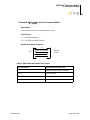
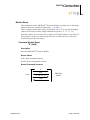
Read Command Structure
Read Commands are used to request information from the Module. Read Commands are
sent from the Host and the ZMOTION™ Detection Module responds with the requested
data.
•
•
All read commands are initiated by single lower-case letters.
Once received, the device returns the applicable value as described in the Serial Commands on page 15.
Command
Host
Response
ZMOTION Module
Figure 5. Read Command Structure
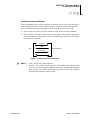
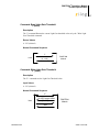
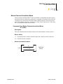
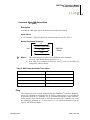
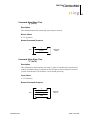
Write Command structure
Write Commands are used to update configuration of the ZMOTION™ Detection Module. The command is sent from the Host, and the Module responds with the current value
as an acknowledgment. Then the Host sends the new data and the Module responds with
an 'ACK'.
•
•
All write commands are initiated by single upper-case letters.
•
When the data value is received, the device returns an 'ACK'. If no data is received after
the inactivity timeout of 2.5 seconds, the device returns a 'NACK'.
Once a write command is received the device returns the current value, and expects an
appropriate single-byte data value.
Command
Current Value
Host
ZMOTION Module
New Value
ACK
Figure 6. Write Command Structure
PS028405-1010
Serial Interface Mode
ZMOTION™ Detection Module
Product Specification
13
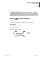
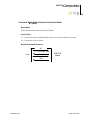
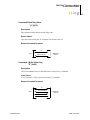
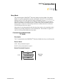
Confirmed Command Structure
Certain commands require a specific sequence of characters to be sent in order to help prevent accidental initiation. These commands require a 4-character confirmation sequence.
Once a command requiring confirmation is received, the device returns an 'ACK'.
•
•
If the sequence is correct, the device returns an 'ACK' and executes the command.
If the sequence is incorrect, or there is an inactivity delay of more than 2.5 seconds between any characters of the sequence, the device immediately sends a 'NACK' and does
not execute the command.
Command
ACK
Host
ZMOTION Module
Sequence(4)
ACK
Figure 7. Confirmed Command Structure
Notes: 1. ACK = 0x06 (ASCII ACK character).
2. NACK = 0x15 (ASCII NACK character). The Module will respond with a
'NACK' on all unrecognized commands, and when command requiring data
(that is, Write, Clear, and Confirmation types) does not receive the required
data within the inactivity timeout period.
PS028405-1010
Serial Interface Mode
ZMOTION™ Detection Module
Product Specification
14
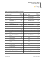
Table 3. Summary of Serial Interface Commands
Command Name
Value
[Default] Command
Value
[Default]
Name
0x61 - 'a'
Read Motion Status
‘Y’, ‘N’,
‘U’
0x6D - 'm’
Read Motion Detected
Unsolicited Mode
‘Y’,’N’
[N]
0x62 - 'b’
Read Current Light Gate Input
Level
0 - 255
0x4D - 'M’
Write Motion Detected
Unsolicited Mode
‘Y’,’N’
0x63 - 'c'
Read /MD//RST Pin
Configuration
'M', 'R'
[R]
0x6F - 'o'
Read /MD Current
Output Active Time
0 - 255
[0]
0x43 - 'C'
Write /MD//RST Pin
Configuration
'M', 'R'
0x4F - 'O'
Write /MD Output State
0 - 255
0x64 - 'd'
Read /MD Activation Time
0 - 255
[2]
0x70 - 'p'
Read Ping Value
0 - 255
[1]
0x44 - 'D'
Write /MD Activation Time
0 - 255
0x50 - 'P'
Write Ping Value
0 - 255
0x65 - 'e'
Read Hyper Sense Setting
'Y', 'N'
[N]
0x72 - 'r'
Read Range Setting
0 - 15
[0]
0x45 - 'E'
Write Hyper Sense Setting
'Y', 'N'
0x52 - 'R'
Write Range Setting
0 - 15
0x66 - 'f'
Read Frequency Response
Setting
'H', 'L'
[L]
0x73 - 's'
Read Sensitivity
0 - 255
[16]
0x46 - 'F'
Write Frequency Response
Setting
'H', 'L'
0x53 - 'S'
Write Sensitivity
0 - 255
0x68 - 'h'
Read Motion Detection
Suspend Setting
'Y', 'N'
[N]
0x75 - 'u'
Read Dual Directional
Mode
'Y', 'N'
[N]
0x48 - 'H'
Write Motion Detection
Suspend Setting
'Y', 'N'
0x55 - 'U'
Write Dual Directional
Mode
'Y', 'N'
0x69 - 'i'
Read Module Software
Version
0 - 255
0x76 - 'v'
Read Single Directional
Mode
'A', '+', '-'
[A]
0x6B - 'k'
Read Serial Interface
Command Mode
'D', 'A'
[D]
0x56 - 'V'
Write Single Directional
Mode
'A', '+', '-'
0x4B - 'K'
Write Serial Interface
Command Mode
'D', 'A'
0x58 - 'X'
Module Reset
'1', '2', '3',
'4'
0x6C - 'l'
Read Light Gate Threshold
0 - 255
[100]
0x79 - 'y'
Read Sleep Time
0 - 255
[0]
0x4C - 'L'
Write Light Gate Threshold
0 - 255
0x59 - 'Y'
Write Sleep Time
0 - 255
0x5A - 'Z'
Sleep Mode
PS028405-1010
'1', '2', '3',
'4'
Serial Interface Mode
ZMOTION™ Detection Module
Product Specification
15
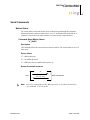
Serial Commands
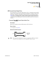
Motion Status
The current status of detected motion can be read and cleared through this command.
When motion has been detected the value is set to 'Y' and latched until read with the 'a'
command. Once cleared, the status remains at 'N' until motion is again detected.
Command: Read Motion Status
“a” (0x61)
Description
This command returns the current status of detected motion. The current status is set to 'N'
when read.
Return Values
'Y' = Motion Detected
'N' = No Motion Detected
'U' = PIR Sensor has not stabilized after power up
Normal Command Sequence
“a”
Host
[“Y”, “N”, “U”]
ZMOTION Module
Note: This value is independent of the /MD output state or the /MD Activation Time
(see commands 'o'/'O' and 'd'/'D').
PS028405-1010
Serial Commands
ZMOTION™ Detection Module
Product Specification
16
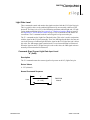
Light Gate Level
These commands control and monitor the signal associated with the LG (Light Gate) pin.
This is typically relative to the ambient light detected by an externally connected CDS
photocell. The range is 0 to 255, with 0 indicating maximum ambient light and, 255 indicating minimum ambient light. See Appendix A—Hardware Interface Mode on page 52
and Appendix B—Serial Interface Mode on page 53 for recommended CDS Photo Cell
connections. The 'b' command reads the current signal level present on the pin.
The "L" command sets the Light Gate Threshold value. This value is used in conjunction
with the signal on the LG pin to internally "Gate" the /MD signal such that it does not activate in the presence of ambient light. When the signal on the LG (Light Gate) pin is below
this value, the /MD output signal remains inactive even when motion has been detected.
When the signal on the LG (Light Gate) pin is above this value, the /MD signal activates
normally when motion has been detected.
Command: Read Current Light Gate Input Level
"b" (0x62)
Description
The "b" command returns the current signal level present on the LG (Light Gate) pin.
Return Values
0 - 255 (decimal)
Normal Command Sequence
“b”
Host
PS028405-1010
[0 – 255]
ZMOTION
Module
Serial Commands
ZMOTION™ Detection Module
Product Specification
17
Command: Read Light Gate Threshold
"l" (0x6C)
Description
The "l" command Returns the current Light Gate threshold value set by the "Write Light
Gate Threshold command.
Return Values
0 - 255 (decimal)
Normal Command Sequence
“l”
Host
[0 – 255]
ZMOTION
Module
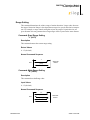
Command: Write Light Gate Threshold
"L" (0x4C)
Description
The "L" command sets the Light Gate Threshold value.
Input Values
0 - 255 (decimal)
Normal Command Sequence
“L”
[0–255] Current Value
Host
[0 – 255]
ZMOTION
Module
ACK
PS028405-1010
Serial Commands
ZMOTION™ Detection Module
Product Specification
18
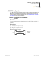
/MD/RST Pin Configuration
The /MD//RST pin can be configured to function as either the Motion Detect output or the
Reset input. This command selects between the two modes. As /RST, a low on this pin
causes the Module to perform a full hardware reset. See Signal Descriptions (Serial Interface Mode) on page 6 for more information.
Command: Read /MD//RST Pin Configuration
"c" (0x63)
Description
This Read command returns the configuration mode of the /MD//RST pin as set by the "C"
command.
Return Values
'M' = /MD//RST pin configured as /MD
'R' = /MD//RST pin configured as /RST
Normal Command Sequence
“c”
Host
PS028405-1010
[“M”, “R”]
ZMOTION
Module
Serial Commands
ZMOTION™ Detection Module
Product Specification
19
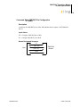
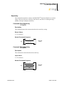
Command: Write /MD//RST Pin Configuration
"C" (0x43)
Description
Configures the /MD//RST pin as either /MD (Motion Detect output) or /RST (Module
Reset).
Input Values
'M' = Configure /MD//RST pin as /MD
'R' = Configure /MD//RST pin as /RST
Normal Command Sequence
“C”
[“M”, “R”]
Host
[“M”, “R”]
ZMOTION
Module
ACK
PS028405-1010
Serial Commands
ZMOTION™ Detection Module
Product Specification
20
/MD Activation Time
The length of time that the /MD pin is held active when motion is detected is configured
by this command. See Table 6 for corresponding values.
Command: Read /MD Activation Time
"d" (0x64)
Description
Returns the /MD pin output activation time value used when motion is detected.
Return Values
0 - 255 (decimal) — See Table 6.
Normal Command Sequence
“d”
Host
PS028405-1010
[0 – 255]
ZMOTION
Module
Serial Commands
ZMOTION™ Detection Module
Product Specification
21
Command: Write /MD Activation Time
"D" (0x44)
Description
Selects the /MD pin output activation time value used when motion is detected.
Input Values
0 - 255 (decimal) - See Table 6.
Normal Command Sequence
“D”
[0–255] Current Value
Host
[0 – 255]
ZMOTION
Module
ACK
Table 4. /MD Output Activation Time Values
Command Value
/MD Output Activation Time
0
Output does not activate on motion
1–127
1–127 seconds
128
Output does not activate on motion
129–255
1–128 minutes
PS028405-1010
Serial Commands
ZMOTION™ Detection Module
Product Specification
22
Hyper Sense
Hyper Sense Mode allows smaller signal changes to be considered valid motion events.
This significantly increases sensitivity at the cost of more potential false motion detections. The typical application for this mode is in occupancy sensing where it is enabled
after valid 'normal' motion has already been detected.
Command: Read Hyper Sense Setting
"e" (0x65)
Description
This command returns the current status of the Hyper Sense setting.
Return Values
'Y' = Hyper Sense Enabled
'N' = Hyper Sense Disabled
Normal Command Sequence
“e”
Host
PS028405-1010
[“Y”, “N”]
ZMOTION
Module
Serial Commands
ZMOTION™ Detection Module
Product Specification
23
Command: Write Hyper Sense Setting
"E" (0x45)
Description
This command enables and disables Hyper Sense mode.
Input Values
'Y' = Hyper Sense Enabled
'N' = Hyper Sense Disabled
Normal Command Sequence
“E”
[“Y”,“N”] Current Value
Host
[“Y”, “N”]
ZMOTION
Module
ACK
PS028405-1010
Serial Commands
ZMOTION™ Detection Module
Product Specification
24
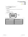
Frequency Response Setting
The Frequency Response setting controls sensitivity to targets producing lower frequencies. When set to "H", sensitivity to targets producing lower frequencies is reduced. This
also has the effect of reducing the distance that the ZMOTION™ Detection Module can
see.
Command: Read Frequency Response Setting
"f" (0x66)
Description
This command returns the current Frequency Response setting of the Module.
Return Values
L = Low and High frequency targets detected
H = Low frequency target sensitivity reduced
Normal Command Sequence
“f”
Host
PS028405-1010
[“L”, “H”]
ZMOTION
Module
Serial Commands
ZMOTION™ Detection Module
Product Specification
25
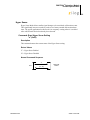
Command: Write Frequency Response Setting
"F" (0x46)
Description
This command sets the Frequency Response of the Module.
Input Values
L = Low and High frequency targets detected
H = Low frequency target sensitivity reduced
Normal Command Sequence
“F”
[“L”,“H”] Current Value
Host
[“L” , “H”]
ZMOTION
Module
ACK
PS028405-1010
Serial Commands
ZMOTION™ Detection Module
Product Specification
26
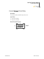
Motion Detection Suspend
This command enables and disables motion detection by the ZMOTION™ Detection
Module. When set to 'N', the Module detects motion. When set to "Y", motion detection is
suspended. While Motion Detection Suspend is a method to temporarily disable motion
detection, the /MD pin may still be manually driven active/inactive via the "O" (Write /
MD Output State) command.
Command: Read Motion Detection Suspend Setting
"h" (0x68)
Description
This read command returns the current Motion Detection Suspend setting.
Return Values
Y = Motion Detection is suspended
N = Motion Detection is active
Normal Command Sequence
“h”
Host
PS028405-1010
[“Y”, “N”]
ZMOTION
Module
Serial Commands
ZMOTION™ Detection Module
Product Specification
27
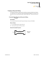
Command: Write Motion Detection Suspend Setting
"H" (0x48)
Description
This write command enables and disables motion detection by the ZMOTION™ Detection
Module.
Input Values
Y = Motion Detection is suspended
N = Motion Detection is active
Normal Command Sequence
“H”
[“Y”,“N”] Current Value
Host
[“Y”, “N”]
ZMOTION
Module
ACK
PS028405-1010
Serial Commands
ZMOTION™ Detection Module
Product Specification
28
Software Revision
The software in the ZMOTION™ Detection Module is made up of two parts:
•
•
Advanced passive infrared software engine
Application software
The S/W Revision command returns the revisions of this software.
The advanced passive infrared software engine is locked into the device and cannot be
changed. This software provides all of the algorithms and processing functions required
for motion detection - Refer to product specification for the Z8FS040 ZMOTION™ MCU
for more details on the operation of this software.
The application software provides the Serial and H/W Interface Mode functionality. It uses
the services provided by the advanced passive infrared software engine for all of the
motion detection functions. This application software is available for download and can be
modified for custom applications. Please see the Zilog Web Site to obtain the application
software project.
See Appendix C on page 54 for version information.
Command: S/W Revision
"i" (0x69)
Description
The 'i' command returns the revision of the software programmed into the ZMOTION™
Detection Module. The first value returned is the application software revision. The second value returned is the advanced passive infrared software engine revision. See Table 8
and Table 9 in Appendix C for a description of software revisions.
Return Values
VAL1 = 0 - 255 (decimal) - Application S/W Version
VAL2 - 0 - 255 (decimal) - ZMOTION™ S/W Engine Version
PS028405-1010
Serial Commands
ZMOTION™ Detection Module
Product Specification
29
Normal Command Sequence
“i”
Host
VAL1, VAL2
ZMOTION
Module
Serial Interface Command Mode
The serial interface can operate in either ASCII or ASCII/Decimal modes. The default is
ASCII/Decimal where commands are sent as ASCII characters, but numeric values sent
and returned are decimal. In ASCII mode, all commands and numeric values are sent and
returned in ASCII. This is useful for demonstration purposes or when using a terminal to
control and monitor the ZMOTION™ Detection Module.
For example, the data for the Sensitivity command is a value from 0 to 255. In ASCII/Decimal mode this would be sent as a single byte (0x00 to 0xFF). In ASCII mode, this would
be sent as 3 bytes: '0','0','0' to '2','5','5'. All values are sent as 3 characters.
Command: Read Serial Interface Command Mode
“k” (0x6B)
Description
This command returns the current command interface mode.
Return Values
'A' = ASCII Mode Enabled
'D' = ASCII/Decimal Mode Enabled (Default)
Normal Command Sequence
“k”
Host
PS028405-1010
[“A”, “D”]
ZMOTION
Module
Serial Commands
ZMOTION™ Detection Module
Product Specification
30
Command: Write Serial Interface Command Mode
“K” (0x4B)
Description
This command selects the command interface mode.
Input Values
'A' = ASCII Mode Enabled
'D' = ASCII/Decimal Mode Enabled
Normal Command Sequence
“K”
[“A”,“D”] Current Value
Host
[“A”, “D”]
ZMOTION
Module
ACK
s
Table 5. /MD Output Activation Time Values
Command Value
/MD Output Activation Time
0
Output does not activate on motion
1–127
1–127 seconds
128
Output does not activate on motion
129–255
1–128 minutes
PS028405-1010
Serial Commands
ZMOTION™ Detection Module
Product Specification
31
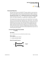
Motion Detected Unsolicited Mode
This mode allows the ZMOTION™ Detection Module to send motion detection status to
the Host unsolicited (without first sending the 'a' command). The Module will send an 'M'
to the Host every time motion is detected. When Unsolicited mode is not used, the Host
must poll the Module using the 'a' command or read the Current Output Active Time using
the "o" to determine motion detection status.
Command: Read Motion Detected Unsolicited Mode
"m" (0x6D)
Description
This read command returns the Motion Detected Unsolicited Mode currently selected.
Return Values
‘Y’ = Unsolicited mode is enabled. Module sends an 'M' each time motion is detected.
‘N' = Unsolicited mode is disabled.
Normal Command Sequence
“m”
Host
PS028405-1010
[“Y”, “N”]
ZMOTION
Module
Serial Commands
ZMOTION™ Detection Module
Product Specification
32
Command: Write Motion Detected Unsolicited Mode
"M" (0x4D)
Description
Enable/disable Motion Detected Unsolicited Mode
Input Values
'Y' = Unsolicited mode is enabled. Module sends an 'M' each time motion is detected.
'N' = Unsolicited mode is disabled.
Normal Command Sequence
“M”
[“Y”,“N”] Current Value
Host
[“Y”, “N”]
ZMOTION
Module
ACK
PS028405-1010
Serial Commands
ZMOTION™ Detection Module
Product Specification
33
/MD Current Active Output Time
This command directly controls the /MD output pin. The "O" command activates the /MD
output pin for the amount of time specified in the command; it is a manual override of the
current state of /MD and is independent of motion detection. The valid range is listed in
Table 6. The "o" command is used to read the remaining time that /MD will be held active
- as initiated by this command or by detected motion. If motion is detected after the "O"
command is given, the /MD output time restarts at the /MD Activation Time set by the "D"
command.
Command: Read /MD Current Output Active Time
"o" (0x6F)
Description
Returns the remaining time that the /MD output pin will be held active.
Return Values
0 - 255 (decimal) - See Table 6.
Normal Command Sequence
“o”
Host
[0 – 255]
ZMOTION
Module
Note: This command is still valid if the /MD pin is configured for /RST. The command
returns the state of /MD pin as if it was configured to indicate motion.
PS028405-1010
Serial Commands
ZMOTION™ Detection Module
Product Specification
34
Command: Write /MD Output State
"O" (0x4F)
Description
Activates the /MD output pin for the amount of activation time desired.
Input Values
0 - 255 (decimal) - /MD activated for the selected amount of time. See Table 6.
Normal Command Sequence:
“O”
[0–255] Current Value
Host
ZMOTION
Module
[0 – 255]
ACK
Notes: 1. This command does not affect the Read Motion Status command
('a') or the Clear Motion Status command ("'A"').
2. If the /MD pin is configured as Reset, the value is saved as if the /MD pin is
configured to indicate motion.
Table 6. /MD Output Activation Time Values
Command Value
/MD Output Activation Time
0
Output does not activate on motion
1–127
1–127 seconds
128
Output does not activate on motion
129–255
1–128 minutes
Ping
This command provides a simple method to ping the ZMOTION™ Detection Module to
ensure it is responding to commands. The "P" writes a value (typically a 1 or a 2) that can
be read back using the "p" command. The "P" command only accepts a single character
written whether it is in ASCII mode or ASCII/Decimal mode ("K" command). For example, sending the command "P", "1" will return '0', '4', '9' in ASCII mode and 0x31 (49 decimal) in ASCII/Decimal mode.
PS028405-1010
Serial Commands
ZMOTION™ Detection Module
Product Specification
35
Command:Read Ping Value
"p" (0x70)
Description
This command returns the last written Ping value.
Return Values
Last value written using the "P" command. The default value is 1.
Normal Command Sequence
“p”
Host
[Return Value]
ZMOTION
Module
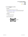
Command: Write Value Ping
"P" (0x50)
Description
This write command stores a value that can be read by the "p" command.
Input Values
0 - 255 (decimal) - Value is stored and read by 'p' command
Normal Command Sequence
“P”
[Current Value]
Host
[New Value]
ZMOTION
Module
ACK
PS028405-1010
Serial Commands
ZMOTION™ Detection Module
Product Specification
36
Range Setting
This command determines the relative range of motion detection. Larger values decrease
the range of detection. Range is also dependent on target size, speed, and relative temperature. For example, a range control setting that rejects one target of a particular size at a
given distance does not guarantee that a larger target will be rejected at the same distance.
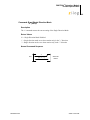
Command: Read Range Setting
"r" (0x72)
Description
This command returns the current range setting.
Return Values
0 - 15 (decimal)
Normal Command Sequence
“r”
Host
[0-15]
ZMOTION
Module
Command: Write Range Setting
"R" (0x52)
Description
This command sets the Range value.
Input Values
0 - 15 (decimal)
Normal Command Sequence
“R”
[0–15] Current Value
Host
[0–15]
ZMOTION
Module
ACK
PS028405-1010
Serial Commands
ZMOTION™ Detection Module
Product Specification
37
Sensitivity
This command controls how sensitive the ZMOTION™ Detection Module is to motion.
Larger values provide lower sensitivity and also have the effect of reducing the range.
Smaller values provide higher sensitivity.
Command: Read Sensitivity
"s" (0x73)
Description
This command returns the current motion detection sensitivity setting.
Return Values
0 - 255 (decimal)
Normal Command Sequence
“s”
Host
[0 – 255]
ZMOTION
Module
Command: Write Sensitivity
"S" (0x53)
Description
This command sets the motion detection sensitivity.
Input Values
0 - 255 (decimal)
Normal Command Sequence
“S”
[0–255] Current Value
Host
[0 – 255]
ZMOTION
Module
ACK
PS028405-1010
Serial Commands
ZMOTION™ Detection Module
Product Specification
38
Directional Detection
Directional Detection places the ZMOTION™ Detection Module in a mode that detects
both positive and negative motion directions. When Dual Direction Mode is enabled via
the 'U' command, motion is detected in either direction and the 'a' and 'M' commands are
enhanced to respond with a '+' or '-' to indicate the direction of the motion target. Single
Direction Mode is enabled via the 'V' command and is similar to the 'U' command except
motion is detected in only one of the '+' or '-' directions as set when the 'V' command is
issued. The 'a' and 'M' commands are not modified when in Single Direction Mode.
The signal generated by the pyro-electric sensor used to discern direction can vary from
device to device, but is consistent for a particular device. Therefore, the '+' and '-' direction
settings can mean either left to right or right to left motion, but will always be the same for
that particular device. Each device can be calibrated simply by creating motion in one or
both directions and observing the results. Other factors such as where the target starts
motion will affect the directional detection capabilities of the ZMOTION™ Detection
Module. Directional detection works best when the target moves horizontally starting
from outside of the range (left or right side) of Module and through the beams of the detection pattern. If the target begins motion while inside the Module detection pattern area, an
incorrect direction can be reported.
Command: Read Dual Direction Mode
“u” (0x75)
Description
The 'u' command returns the current Dual Direction Mode setting.
Return Values
'N' = Dual Direction Mode Disabled
'Y' = Dual Direction Mode Enabled
Normal Command Sequence
“u”
Host
PS028405-1010
[“Y”, “N”]
ZMOTION
Module
Serial Commands
ZMOTION™ Detection Module
Product Specification
39
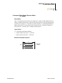
Command: Write Dual Direction Mode
“U” (0x55)
Description
Enable directional detection in both '+' and '-' directions.
When Dual Direction mode is enabled, the 'a' command (Read Motion Status) and 'M'
command (Motion Detected Unsolicited Mode) provide the directional information:
'+' = Motion detected in the '+' direction
'-' = Motion detected in the '-' direction
Input Values
'N' = Dual Direction Mode Disabled
'Y' = Dual Direction Mode Enabled
Normal Command Sequence
“U”
[“Y”,“N”] Current Value
Host
[“Y”, “N”]
ZMOTION
Module
ACK
PS028405-1010
Serial Commands
ZMOTION™ Detection Module
Product Specification
40
Command: Read Single Direction Mode
“v” (0x76)
Description
The 'v' command returns the current setting of the Single Direction Mode.
Return Values
'A' = Single Direction Mode Disabled
'+' = Single direction mode set to detect motion only in the "+" direction
'-' = Single direction mode set to detect motion only in the "-" direction
Normal Command Sequence
“v”
Host
PS028405-1010
[“A”, “+”, “-“]
ZMOTION
Module
Serial Commands
ZMOTION™ Detection Module
Product Specification
41
Command: Write Single Direction Mode
“V” (0x56)
Description
The 'V' command selects the direction of motion to be detected. When Single Direction
Mode is enabled, motion status is reported only when motion is detected in the direction
specified. For example, if '+' direction is specified, then the 'a' command (Read Motion
Status) will return a 'Y' only when motion is detected in the '+' direction. If motion is
detected in the '-' direction, the 'a' command would return 'N'.
Input Values
'A' = Single Direction Mode Disabled
'+' = Detect motion only in the "+" direction
'-' = Detect motion only in the "-" direction
Normal Command Sequence
“V”
[“A”,“+”,”-“] Current Value
Host
[“A”, “+”, “-“]
ZMOTION
Module
ACK
PS028405-1010
Serial Commands
ZMOTION™ Detection Module
Product Specification
42
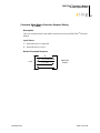
Module Reset
This command forces the ZMOTION™ Detection Module to perform a reset. All configuration and status are returned to default values — see Table 3.
This is a special command that requires confirmation. Once "X" is received, the Module
sends an 'ACK' and expects the 4-digit confirmation sequence ("1", "2", "3", "4").
Once this sequence is received the device sends an 'ACK' and performs a reset. If the confirm sequence is incorrect or the inactivity timeout is exceeded, the device will send a
'NACK' and ignore the reset request.
Command: Module Reset
"X" (0x58)
Description
Reset the ZMOTION™ Detection Module.
Return Values
ACK = Reset command accepted
NACK = Reset command not accepted
Normal Command Sequence
“X”
ACK
Host
“1”, “2”, “3”, “4”
ZMOTION
Module
ACK
PS028405-1010
Serial Commands
ZMOTION™ Detection Module
Product Specification
43
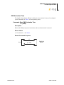
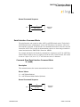
Command: Read Sleep Time
"y" (0x79)
Description
This command returns the current sleep time setting in seconds.
Return Values
0 - 255 (decimal)
Normal Command Sequence
“y”
Host
[0-255]
ZMOTION
Module
Command: Write Sleep Time
"Y" (0x79)
Description
This command sets the Sleep time in seconds. A value of 0 disables the sleep timer and
wake up is initiated only by a transition on the /SLP pin or when a character is received
over the serial interface (The character is received and processed).
Input Values
0 - 255 (decimal)
Normal Command Sequence
“Y”
[0–255] Current Value
Host
[0–255]
ZMOTION
Module
ACK
PS028405-1010
Serial Commands
ZMOTION™ Detection Module
Product Specification
44
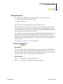
Sleep Mode
This command places ZMOTION™ Detection Module into Sleep Mode. Sleep Mode
Enable is a special command that requires confirmation. Once the "Z" is received, the
Module sends an 'ACK' and expects the 4-digit confirmation sequence ("1", "2", "3", "4").
Once this sequence is received the device sends an 'ACK' and enters low power Sleep
Mode for the number of seconds set by the 'Y' (Write Sleep Time) command. If the confirm sequence is incorrect or the inactivity timeout is exceeded, the device will send a
'NACK' and ignore the reset request.
Sleep mode is exited automatically when the sleep time expires or by a transition on the /
SLP pin or by sending a character over the serial interface - this character is ignored. A
value of 0 for sleep time disables the sleep timer.
Command: Sleep Mode Enable
"Z" (0x5A)
Description
The 'Z' command places the ZMOTION™ Detection Module into low power Sleep mode.
Return Values
ACK = Sleep command accepted
NACK = Sleep command not accepted
Normal Command Sequence
“Z”
ACK
Host
“1”, “2”, “3”, “4”
ZMOTION
Module
ACK
PS028405-1010
Serial Commands
ZMOTION™ Detection Module
Product Specification
45
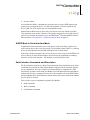
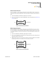
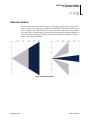
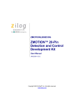
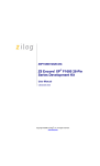
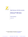
Detection Pattern
The Fresnel lens directs the infrared energy from the target on to the pyro-electric sensor.
Figure 8 shows the coverage area provided by the ZMOTION™ Detection Module. It provides a 60 degree cone with 4 beams. The two inner beams provide greater range than the
two outer beams. The actual range is affected by ambient temperature and the settings provided to the Module (Sensitivity, Range, Hyper Sense and Frequency Response all contribute to the range performance).
Figure 8. Detection Pattern
PS028405-1010
Detection Pattern
ZMOTION™ Detection Module
Product Specification
46
Mechanical Information
5.35±0.2
6.10±0.2
1.60±0.2
10.55±0.2
16.80±0.3
9.00±0.2
8.00±0.2
7.0±0.2
5.3±0.2
3.55±0.1
25.40±0.5
3.95±0.2
21.73±0.2
Figure 9. Mechanical Drawing of ZMOTION™ Detection Module
PS028405-1010
Mechanical Information
ZMOTION™ Detection Module
Product Specification
47
ZMOTION™ Detection Module Schematic
Figure 10 displays the schematic of ZMOTION™ Detection Module.
Figure 10. Schematic of ZMOTION™ Detection Module
PS028405-1010
ZMOTION™ Detection Module Schematic
ZMOTION™ Detection Module
Product Specification
48
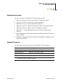
Related Documents
The related documents for ZMOTION™ Detection Module include:
•
•
•
•
•
•
ZMOTION™ Detection Module Evaluation Kit User Manual (UM0223)
•
Power Management and Customer Sensing with Zilog's ZMOTION™ Detection
Module (AN0301)
•
ZMOTION™ Detection and Control Family Featuring PIR Technology Product
Specification (PS0285)
Z8 Encore! XP® F082A Series Product Specification (PS0228)
ZMOTION™ Detection Module Product Brief (PB0223)
ZMOTION™ Detection Module Development Kit Quick Start Guide (QS0073)
ZMOTION™ Detection Module Application Walkthrough (AN0307)
ZMOTION™—A New PIR Motion Detection Architecture White Paper
(WP0017)
Related Products
The table below lists the products related with ZMOTION™ Detection Module.
Product Number
Product Description
Z8FS040BSB20EG
ZMOTION™ MCU (8 pin SOIC)*
Z8FS040BHH20EG
ZMOTION™ MCU (20 pin SOIC)*
Z8FS040BHJ20EG
ZMOTION™ MCU (28 pin SOIC)*
ZEPIR000102ZCOG
ZMOTION™ Detection Module Evaluation Kit
Note: *See Zilog’s ZMOTION™ Detection and Control Family Featuring PIR Technology Product
Specification (PS0285), available on Zilog.com.
PS028405-1010
Related Documents
ZMOTION™ Detection Module
Product Specification
49
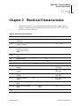
Chapter 2 Electrical Characteristics
The data in this chapter is pre-qualification and pre-characterization and is subject to
change. For additional electrical characteristics, refer to Z8 Encore! XP® F082A Series
Product Specification (PS0228).
Table 5. Electrical Characteristics
Symbol
Parameter
Min
Typ
Max
Units
Conditions
VPOR
Power-on Reset Voltage
Threshold
2.20
2.45
2.70
V
VDD = VPOR
VVBO
Voltage Brownout Reset
Voltage Threshold
2.15
2.40
2.65
V
VDD = VPOR
TRAMP
Time for VDD to
transition from VSS to
VPOR to ensure valid
Reset
0.10
—
100
ms
—
TPOR
Power-on Reset Digital
Delay
—
1.0
—
ms
—
VDD
Supply Voltage
2.7
—
3.6
V
—
VIL1
Low Level Input Voltage
-0.3
—
0.3*VDD
V
RXD, /RST, /SLP
VIH1
High Level Input Voltage 0.7*VDD
—
5.5
V
RXD, /RST, /SLP
VOL1
Low Level Output
Voltage
—
—
0.4
V
IOL = 2 mA; VDD = 3.0 V
TXD, /MD
VOL2
Low Level Output
Voltage
—
—
0.6
V
IOL = 20 mA; VDD = 3.3 V
TXD, /MD
VOH1
High Level Output
Voltage
2.4
—
—
V
IOH = -2 mA; VDD = 3.0 V
TXD, /MD
VOH2
High Level Output
Voltage
2.4
—
—
V
IOH = -20 mA; VDD = 3.3 V
TXD, /MD
IDD Active Supply Current in Active
Mode
—
8.9 mA
—
—
VDD = 3.3 V
IDD Sleep
Supply Current in Sleep
Mode
—
600 uA
(Typ)
—
—
VDD = 3.3 V
TPIR
PIR Stabilization Time
—
20
—
PS028405-1010
seconds —
Electrical Characteristics
ZMOTION™ Detection Module
Product Specification
50
Table 5. Electrical Characteristics (Continued)
Symbol
Parameter
Min
Typ
Max
ZIN
Units
Conditions
Analog Pin Input
Impedance
—
550
—
K
Serial Interface Inactivity
Timeout
—
2.5
—
seconds —
DLY, SNS, LG
Absolute Maximum Ratings
Stresses greater than those listed in Table 6 can cause permanent damage to the device.
These ratings are stress ratings only. Operation of the device at any condition outside those
indicated in the operational sections of these specifications is not implied. Exposure to
absolute maximum rating conditions for extended periods may affect device reliability.
For improved reliability, unused inputs should be tied to one of the supply voltages (VDD
or VSS).
Table 6. Absolute Maximum Ratings
PS028405-1010
Parameter
Min
Max
Units
Ambient Temperature Under Bias
0
70
°C
Storage Temperature
-65
+150
°C
Voltage on Any Pin with respect to VSS
-0.3
+5.5
V
Voltage on VDD Pin with respect to VSS
-0.3
+3.6
V
Maximum Output Current from Active Output Pin
-25
+25
mA
Electrical Characteristics
ZMOTION™ Detection Module
Product Specification
51
Chapter 3 Ordering Information
You can order the ZMOTION™ Detection Module from Zilog® or any of our authorized
distributors using the following part numbers. For more information on ordering, please
consult your local Zilog sales office. The Zilog website www.zilog.com lists all regional
offices and provides additional information about ZMOTION™ Detection Module product line.
Part Numbers
Table 7 lists the part numbers for ZMOTION™ Detection Module and a brief description
of each part.
Table 7. Part Numbers
PS028405-1010
Part Number
Description
ZEPIR0AAS02MODG
ZMOTION™ Detection Module
ZEPIR000102ZCOG
ZMOTION™ Detection Module Evaluation Kit
Ordering Information
ZMOTION™ Detection Module
Product Specification
52
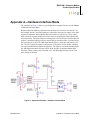
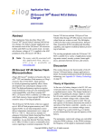
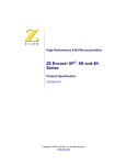
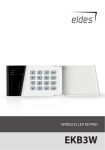
Appendix A—Hardware Interface Mode
The schematic in Figure 11 shows a typical application example of how to use the Module
in Hardware Interface Mode.
Hardware Interface Mode is selected because the Sense pin is between 0V and 1.8V. In
this example, the DLY and SNS signals are connected to trim pots for control of the /MD
output activation time and the Motion Detection sensitivity respectively. These connections can also be replaced with fixed resistor values in an application where adjustments
are not necessary. The Sleep feature is not being used so the /SLP input is left unconnected
as there is an internal pull-up resistor to ensure this pin remains inactive. It is also acceptable to tie this pin to Vdd. The /MD signal directly drives a solid state relay and is active
low. The LG (Light Gate) signal is connected to a CDS photo cell in a divider configuration with a potentiometer to adjust the light level. The signal is used by the Module to gate
the /MD signal such that it does not activate in the presence of daytime ambient light.
When the voltage on this pin is lower than 1.0 V, the /MD signal will not activate even
when motion is detected.
Figure 11. Application Example - Hardware Interface Mode
PS028405-1010
Appendix A—Hardware Interface Mode
ZMOTION™ Detection Module
Product Specification
53
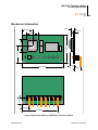
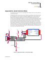
Appendix B—Serial Interface Mode
The schematic in Figure 12 shows a typical application example of how to use the module in
Serial Interface Mode.
Serial Interface Mode is selected because the TXD pin is pulled High via the 10K ohm resistor
R1. This High state is only required to be guaranteed during power up. In this example, the
RXD and TXD signals are connected to the TXD and RXD signals (respectively) of the
Z8F1680. Since the /MD and /SLP signals are still active in the Serial Interface Mode, they are
also connected to the host MCU. If they were not connected to the MCU, /MD would typically
drive the control circuitry similar the Hardware Interface Mode and /SLP either left unconnected or tied high. /SLP has an internal pull-up to ensure proper operation. The LG (Light
Gate) signal is connected to a CDS photo cell in a divider configuration with a potentiometer to
adjust the light level. The signal is used by the Module to gate the /MD signal such that it does
not activate in the presence of daytime ambient light. When the signal on this pin is lower than
lower than the value programmed into the Light Gate Threshold register, the /MD signal will
not activate even when motion is detected.
U1
+3.3V
+3.3V
+3.3V
C1
1uF
GND
PB1/ANA1/AMPINN
PB2/ANA2/AMPINP
PB3/CLKIN/ANA3
VDD
PA0/T0IN/T0OUT/XIN
PA1/T0OUT/XOUT
VSS
PA2/DE0
PA3/CTS0
PA4/RXD0
>>>SERIAL>>>
TXD/SENSE
(OPTIONAL)
/MD/RESET
<<<SERIAL<<<
LIGHT GATE
(OPTIONAL)
/SLEEP/DBG
+3.3V
R2
100K
LIGHT LEVEL
R3
CDS 100K
Figure 12. Application Example - Serial Interface Mode
PS028405-1010
PB0/ANA0/AMPOUT
PC3/COUT/LED
PC2/ANA6/LED
PC1/ANA5/CINN/LED
PC0/ANA4/CINP/LED
DBG
RESET/PD0
PA7/T1OUT
PA6/T1IN/T1OUT
PA5/TXD0
Z8F1680
RXD/DELAY
GND
1
2
3
4
5
6
7
8
VDD
R1
100K
1
2
3
4
5
6
7
8
9
10
20
19
18
17
16
15
14
13
12
11
ZMOTION™ Detection Module
Product Specification
54
Appendix C
Table 8. ZMOTION™ Detection Module S/W Revision (Application S/W)
Returned Value
(‘i’ command)
S/W Revision
Changes/Updates
1
1.0
Initial Production Release
2
2.0
Support for additional features in ZMOTION™
Detection Module. Added ASCII serial mode, RAM R/
W, and sleep timer. Improved sleep mode current.
Table 9. ZMOTION™ S/W Engine Revision
Returned Value
(‘i’ command)
S/W Revision
Changes/Updates
1
1.0
Initial Production Release
2
2.0
Release of ZMOTION™ Detection MCU Family.
Improved detection/stability. Added Range, Low
Power, Hyper Sense, Advanced API features.
PS028405-1010
Appendix C
ZMOTION™ Detection Module
Product Specification
55
Customer Support
To share comments, get your technical questions answered, or report issues you may be
experiencing with our products, please visit Zilog’s Technical Support page at http://support.zilog.com.
This publication is subject to replacement by a later edition. To determine whether a later
edition exists, please visit the Zilog website at http://www.zilog.com.
PS028405-1010
Customer Support