1
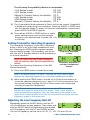
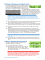
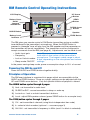
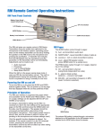
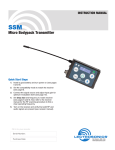
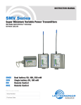
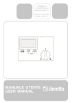
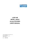
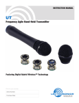
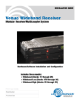
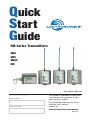
Quick
Start
Guide
SM Series Transmitters
sma
smv
smqv
rm
U.S. Patent 7,225,135
Fill in for your records:
Serial Number:
This guide is intended to assist with
initial setup and operation of your
Lectrosonics product.
Purchase Date:
For a detailed user manual, download the most current
version at:
www.lectrosonics.com/manuals
06 jun10
Controls and Functions
LCD Screen
Battery
Compartment
Cover Plate
UP Arrow
Antenna
Battery
Compartment
Opener
DOWN Arrow
Modulation
LEDs
Audio
Input Jack
Power LED
AUDIO Button
FREQ Button
(Tuning)
LCD Screen
Used to display the status of the selected function.
Power LED
Indicates power status and battery strength.
Audio Input Jack
Accommodates most lavaliere and dynamic microphones, and line level
signals.
Modulation LEDs
Provides a visual indication of the audio input signal level - either red or green
to indicate modulation levels.
Audio Button
Used to display the audio level setting (0 dB to 44 dB) on the LCD and used
with the Up and Down arrows to adjust the audio level input from the microphone.
FREQ Button
Used to set the operating frequency and toggle the LCD between the operating
frequency in MHz and a two-digit hexadecimal frequency code.
Up/Down Arrows
Used to adjust the selected function or parameter.
Battery Compartment, Cover Plate and Opener
Used to install or remove battery/batteries.
2
LECTROSONICS, INC.
Operating Instructions
Power On
1) Ensure that good batteries are installed.
2) Simultaneously press and hold the AUDIO
and FREQ buttons until the Power On Boot
Sequence is initiated (3 seconds).
Initial Power On
Timer Screen
Power Off
1) Simultaneously press and hold the AUDIO and
FREQ buttons while observing that the word
“Off” appears in the LCD along with a counter.
2) When the counter reaches “0”, the unit turns off.
Initial Power Off
Timer Screen
Note: If the AUDIO and FREQ buttons are
released before the end of the countdown, the unit will not turn off.
Standby Mode
From the “OFF” position, quickly press and release
both the AUDIO and FREQ buttons simultaneously
to enter and exit this mode. Allows the user to verify
or change the transmitter’s operating frequency or
audio input level without transmitting any signals.
Standby Screen
Selecting the Compatibility Mode and Power (SMV & SMQV ONLY)
SM Series transmitters will work with all Digital
Hybrid Wireless® receivers in the native, compandorless mode. They are also capable of working with
200 Series, 100 Series and IFB analog receivers,
plus some other brands of analog wireless receivers (contact the factory for details).
400 Series or Digital
Hybrid Wireless™
Compatibility Mode
Note: RF transmission is prevented while selecting Compatibility
Modes. Also, the SM exits the Compatibility Mode screen to Standby
Mode. (See Standby Mode, this section.)
Note: The unit comes from the factory configured as a 400 Series
transmitter.
1) Set the receiver’s audio controls to minimum.
2) Power up the SM and observe the Boot Sequence. If the Compatibility
Mode for the SM does not match the corresponding receiver, then power
off the SM transmitter.
3) From a power off condition, press and hold the Up arrow, then press the
AUDIO and FREQ buttons simultaneously.
4) The LCD will display the current Compatibility Mode. Use the Up or
Down arrow buttons to set the Compatibility Mode to match the corresponding receiver.
www.lectrosonics.com
3
The following Compatibility Modes are selectable:
• 100 Series mode: • 200 Series mode: • Mode 3 (Contact factory for details): • 400 Series mode:
• IFB Series mode:
• Mode 6 (Contact factory for details): CP 100
CP 200
CP 3
CP 400
CP IFB
CP 6
5) The Compatibility Mode selected in Step 4 will be the current Compatibility Mode until reset using this procedure. Pressing AUDIO or FREQ exits
into the Standby Mode. To power off from the compatibility mode screen,
press AUDIO and FREQ together.
6) Press either AUDIO or FREQ button to select
power setting screen and use the up/down
arrows for your desired level of power (50, 100
or 250mw).
Setting Transmitter Operating Frequency
The Operating Frequency of the SM is displayed
either in MHz or as a two-digit hexadecimal number. Pressing the FREQ button toggles between
the two display modes. The frequency can be set
with the unit in Standby Mode or while powered up
for normal operation.
Note: You must first find a clear frequency
with the receiver, then set the transmitter to
match.
Frequency displayed
in MHz
Frequency displayed as
two-digit hexadecimal
number
To change the Operating Frequency of the SM
Series transmitter:
1) Press the FREQ button to enter this screen.
Note: The default display is in MHz. Pressing the FREQ button again
displays the operating frequency as a two-digit hexadecimal number.
2) While holding the FREQ button, use the Up or Down arrow buttons to
move the operating frequency up or down in 100 kHz increments from
the current setting. Holding the Up or Down arrows will cause rapid
scrolling through the frequencies.
Note: The operating frequency displayed on the LCD wraps as it
reaches the upper or lower end of its range. Thus, if you intend to
move the operating frequency from the lower end of the range to the
upper end, it may be faster to do this by using the Down arrow until the
frequency wraps to the upper end.
Adjusting the Low Frequency Roll-off
Repeatedly press the AUDIO button until the LF
roll-off adjustment screen appears. Then press and
hold the AUDIO button while selecting the desired
roll-off frequency with the UP and DOWN arrows.
The roll-off frequency can be set to 35, 50, 70, 100, 120 and 150 Hz.
4
LECTROSONICS, INC.
Attaching a Microphone and Adjusting Gain
The front panel Modulation LEDs indicate limiter activity. (See chart below.) Once set, the transmitter’s
audio level setting should not be used to control
the volume of your sound system or recorder levels.
This gain adjustment matches the transSignal Level
-20 LED
-10 LED
mitter gain with the microphone’s output
Off
Off
Less than -20 dB
level, the user’s voice level and the microGreen
Off
-20 dB to -10 dB Green Green
-10 dB to +0 dB
phone’s position. The audio input level can
Red
Green
+0 dB to +10 dB
be set with the unit in Standby Mode or
Red
Red
Greater than +10 dB
powered up for normal operation.
Note: Different voices will usually require different settings of the
AUDIO control, so check this adjustment for each person using the
system. If several different people will be using the transmitter and
there is not time to make the adjustment for each individual, adjust it for
the loudest voice.
1) With the SM powered off, insert the microphone plug into the Audio Input
Jack, aligning the pins and ensuring that the connector locks.
2) Place the SM in Standby Mode, or if the unit is to be powered up and adjusted, mute the main sound system prior to powering up the transmitter.
3) Position the microphone in the location where it will be used in actual
operation.
4) Observe the SM audio level LEDs while speaking or singing into the
microphone at the same voice level that will be used during the program.
While holding the AUDIO button, press the Up or Down arrow buttons
until the both the -20 and -10 LEDs glow green, with the -20 LED occasionally flickering red (+0 dB to +10 dB range during peaks).
Note: Setting the audio level too high reduces the dynamic range of the
audio signal. Setting the audio level too low may cause hiss and noise
in the audio.
5) If the unit was set up in Standby Mode, it will be necessary to power up
the SM and adjust the remaining components of the audio system prior to
use.
Locking or Unlocking the Control Panel
The Lock mode protects the transmitter from
accidental changes to its settings.
1) Ensure the SM setup is complete.
2) Simultaneously press both the Up and Down
arrow buttons to start the Lock timer. When
the timer reaches zero, “Loc” is displayed and
the controls are locked.
Important: The only ways to unlock a locked transmitter are to remove
the battery or unlock it via the remote control. It cannot be unlocked
or powered off using the buttons. The remote control will work only if
the transmitter was previously configured to respond to the remote
control. The unit will always power up in “unlocked” mode.
www.lectrosonics.com
5
Battery Installation
We recommend using lithium or high-capacity
rechargeable batteries for longest life.
Note: Standard zinc-carbon batteries marked
“heavy-duty” or “long-lasting” are not adequate.
The battery status circuitry is designed for the voltage drop over the life of lithium batteries.
To install new batteries:
1) Turn the Battery Cover Plate Opener counterclockwise, open the battery compartment and remove any old batteries.
2) Insert the new battery (or batteries) into the housing, positive (+)
terminal first.
Important: On dual-battery transmitters, BOTH
batteries go positive (+) terminal first.
3) Replace the Battery Cover Plate and tighten the Opener.
Configuring for Remote Control Use
Some transmitter settings can be changed with the
Lectrosonics RM Remote Control. However, you
must first configure the SM Series transmitter to
accept commands from the RM:
1) Press and hold the Down Arrow Button then
power on the transmitter by pressing the
Audio and Freq buttons simultaneously.
Remote Control Screens
2) The LCD will display the status, either “rc ON” or “rc OFF.” To change the
setting, press the Up or Down arrow button.
3) Power Off the transmitter by pressing the Audio and Freq buttons simultaneously. The RC setting will persist when you Power Up the transmitter
again.
Note: SM Series transmitters with firmware version 1.6 and later are
factory set to “rc ON” by default.
Configuring for Power Restore (SMV & SMQV ONLY)
When using external power source through a
battery eliminator, Power Restore will return
your transmitter to settings it had before it was
powered off. This eliminates the need to power on
through the unit itself.
1) Press and hold the Down Arrow Button then
power on the transmitter by pressing the
Audio and Freq buttons simultaneously.
Power Restore Screens
2) The LCD will display the status, either “rc ON” or “rc OFF.” Press “AUDIO”
or “FREQ” key to scroll to the “PbAc 0” setting and use arrow keys to
turn to “PbAc 1” for on.
3) When power is restored the unit will turn on with previous settings.
6
LECTROSONICS, INC.
RM Remote Control Operating Instructions
LCD Display
UP Arrow
Button
Battery Cover
Knob/
Lanyard
Attachment
SEND
Button
DOWN Arrow
Button
AUDIO Button
Speaker
Battery Level
Indicator
FREQ Button
The RM gives you remote control of SM Series transmitters using an audible
tone delivered to the transmitter’s microphone. When the SEND button is
pressed, a “dweedle” tone will play from the RM speaker and the parameter on
the transmitter will be set immediately. The transmitter must be configured to
accept commands from the RM (see page 6). Adjustments can be made to set:
• Audio input gain
Note: The speaker should be uncovered and
held within a few inches of the transmitter’s
microphone. The longest usable range is about
• Lock or Unlock modes 6 feet, depending on the microphone and volume
• Sleep mode ON/OFF settings.
• Frequency
In the power saving sleep mode, power consumption drops to 20% of normal.
Powering the RM On and Off
Press the AUDIO and FREQ buttons together briefly.
Principles of Operation
The RM user interface is organized into pages which are accessible via the
AUDIO and FREQ buttons. Once on a page, settings can be adjusted with the
UP and DOWN arrow buttons. Only the specific function displayed is altered.
The AUDIO button cycles through 4 pages:
1) Aud - set transmitter’s audio level
2) SLEEP/unSLP - cause transmitter to sleep or wake up
3) Loc/unLoc - lock or unlock transmitter’s buttons
4) Loud - adjust RM speaker volume (press SEND button for a sample tone)
The FREQ button cycles through 3 pages:
1) CH - set transmitter’s channel (using block-independent hex code)
2) b - select a block number (optional — uncovers page 3)
3) 000.000 - set transmitter’s frequency in MHz (avail. if a block is selected)
www.lectrosonics.com
7