1
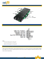
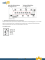
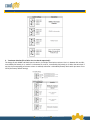
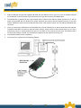
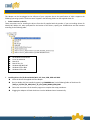
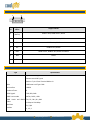
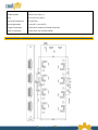
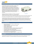
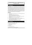
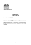
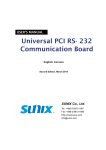
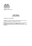
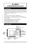
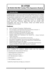
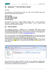
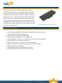
SG-PCIE8SRS422485MOD 8 Port PCI Express RS232 / 422 / 485 Module Manual This high performance 8-port RS232/422/485 Combo to USB 2.0 Module Box product includes a metal module box and a USB cable. Each box has an upstream and a downstream USB ports to support multiple units installed in daisy-chain mode. It supports 8 serial ports which can be set in any combinations of RS232, RS422, RS485-2W, or RS485-4W modes. The UART based serial ports (2K-byte deep FIFO) are fully 16C550 UART compatible with most of the RS232C, RS422 and RS485 devices available from the market. The Isolation and Surge Protection model supports 2,500Vrms and 15KV ESD surge protection feature for critical applications. SG-PCIE8SRS422485MOD PCI Express Module Specifications and Features • • • • • • • • • • • USB 2.0 High Speed (480Mbits/Second) and Full Speed (12Mbits/Second) Compatible Supports 8 RS232/422/485 Combo Serial Ports RS232 Supports 3-wire Signals (TXD, RXD, GND) Supports 4-wire RS422, RS485 and 2-wire RS485 Modes Supports RS485 Auto Transceiver Turn Around by Unique Featured ATTATM Hardware 128-byte deep FIFO per transmitter and receivers Each Serial Port Supports 7-pin Screw-Lock-type Terminal Blocks Supports one Downstream USB2.0 Port for Daisy-chain Expansion Modules Supports Baud Rate up to 921.6Kpbs Optional Model: Isolated and 15KV ESD Surge Protection Supports Win2000, XP, 2003, 2008, Vista, Win 7, and Linux [email protected] www.CoolGear.com Connector Layout Port 5 Port 6 Port 4 Port 7 Port 8 Port 3 Port 2 Wall Mounting Ear Port 1 7-pin Terminal Blocks Pin Assignment for Port 1 ~ 8 LEDs: T (Green): Blinking when sending data R (Green): Blinking when receiving data Mode and Terminator Setting Switches There are 16 4-pin DIP switches on the back side of the box for Port 1 to Port 8. 8 of them are mode switches (marked M1 to M8 for Port 1 to Port 8 respectively) and the other 8 are terminator configuration switches (marked T1 to T8 for Port 1 to Port 8 respectively). [email protected] www.CoolGear.com 1. Mode Switches (M1 to M8 for Port 1 to Port 8 respectively): Each M1 to M8 has 4 switch pins which were marked their function names as the following diagram. Pin 1 is to enable RS485 2 wire mode (when ON), pin 2 enables RS485 4 wire mode (ON), pin 3 enables RS422 mode (ON) and pin 4 enables Echo option (ON). Please refer to the following table for more detail. M1 to M8 DIP Switches: [email protected] www.CoolGear.com Mode Setting Table 2. Terminator Switches (T1 to T8 for Port 1 to Port 8 respectively): The design of each RS485 and RS422 port has built-in 2 120 Ohm termination resistors. One is in between RX+ and RX-, controlled by DIP switch pin 1; another is in between TX+ and TX-, controlled by DIP switch pin 2. When the switch pin is set ON, the corresponding terminator resistor is enabled; otherwise it is disabled (floated). Both switch pins were set to OFF by the factory default settings. [email protected] www.CoolGear.com Installing the Module Box 1. Plug the USB Type-A end of the supplied USB cable into the USB host port on your PC or into an available USB port on an USB hub. Connect the other Type-B end to the rear Type-B connector of this Module Box. 2. The Module Box is powered by the 2-pin terminal blocks instead of the USB bus, please connect the +7~12V DC power (not provided with this product) for proper operation (the polarity must be applied correctly). If you have another USB device need to be connected with daisy-chain mode, please connect it to the USB Type-A downstream connector. 3. If you are connecting a RS232 device to the Module Box, then the 3 RS232 pins on the terminal blocks are required. The RS232 mode does not need any extra DIP switch settings, simply connect to the terminal blocks’ pin 5, 6 and 7 and left the rest pin 1~4 unconnected. Each port can only work in one mode at the same time. The RS232 mode is not set by DIP switches. Instead, it is automatically supported by the separate connector pins. 4. Proceed with Software Driver Installation. 5. The connection is explained as the following diagram: [email protected] www.CoolGear.com Software Installation This Adapter can be hot-plugged to the USB port of your computer due to the specifications of USB. It supports the following operating systems. The drivers were shipped in the following folders on the supplied driver CD. 1. Driver Locations on the CD These instructions are for installing the drivers from the CD supplied with the product. If you are installing drivers for Win98, ME, 2000 or XP, when prompted for the location of the drivers, specify your CD-ROM drive and the locations according to the following table: 2. All Windows 32 and 64-bit Linux 32 and 64-bit Mac OS X Mac OS 9.x, 8.x Windows 98, 98SE, ME Windows CE for ARM Windows CE for ix86 Installing Drivers for (32-bit and 64-bit) Win7, XP, Vista, 2008, 2003 and 2000: Insert the Driver CD supplied with the Adapter. Run (or double click) the Installer Program (e.g. CDM20600.exe ) in the following folder of the driver CD: \USB_to_IO\FTDI\ (32_64bit) Win7_XP_Vista_2008_2008R2_2003_2000 Follow the instructions of the installer program to complete the setup procedures. Plugging the Adapter will hook the drivers into the Windows kernel automatically. [email protected] www.CoolGear.com Terminal Blocks Pin Assignments 1 7 Pin No. Signal Name Support Modes 1 TX+ (DATA+) RS485 2-wire, RS485 4-wire, RS422 2 TX- (DATA-) RS485 2-wire, RS485 4-wire, RS422 3 RX+ RS485 4-wire, RS422 4 RX- RS485 4-wire, RS422 5 GND RS485 2-wire, RS485 4-wire, RS422 and RS232 6 RXD RS232 7 TXD RS232 Specifications Type Connectors Specifications Upstream USB: Type-B Downstream USB: Type A Devices: 7-pin 3.5mm Terminal Blocks x 8 Cable USB Screw-Lock-Type Cable Bus Interface USB2.0 Number of Ports 8 RS232 Signals TXD, RXD, GND RS485 2-wire mode DATA+, DATA-, GND RS485 4-wire and RS422 TX+, TX-, RX+, RX-, GND modes 110 bps to 921.6Kbps Baud Rate 5,6,7,8,9 Data Bits 1, 1.5, 2 [email protected] www.CoolGear.com Stop Bits Plug-and-Play (various) I/O address/IRQ None, Even, Odd, 1, 0 Parity 0 to 55°C(32 to 132°F) Operating Temperature 5 to 95% RH Operating Humidity -20 to 85°C (-4 to 185°F) Storage Temperature 12V/0.5A for Isolation and Surge Protection Power Consumption 12V/0.2A for non-Isolation Model Mechanical Drawing [email protected] www.CoolGear.com