1
CT-10G-MC series
Media Converter
User’s Manual
CT-10G-MC Ver 1.1
2
Revision History
Date
2011/05/06
2011/08/01
Version
1.0
1.1
History
First draft version
Add XFP2 version
3
Table of Contents
Foreword ..........................................................................................................................................2
Revision History ..............................................................................................................................3
1. CT-10G-MC series Overview.......................................................................................................6
1.1. General Descriptions of CT-10G-MC ................................................................................6
1.2. Features, Key Advantages, and Main Applications of CT-10G-MC series ....................7
1.3. CT-10G-MC series Functions Overview ...........................................................................8
1.3.1. CT-10G-MC series Outer Case .....................................................................................8
1.3.2. CT-10G-MC series Front Panel.....................................................................................9
A. Front Panel of CT-10G-MC-SFP+2 series......................................................................9
B. Front Panel of CT-10G-MC-XSFP+ series ...................................................................10
C. Front Panel of CT-10G-MC-SFP+ series...................................................................... 11
D. Front Panel of CT-10G-MC-CX4 series........................................................................12
E. Front Panel of CT-10G-MC-XFP2 series ......................................................................13
F. Front Panel of CT-10G-MC-XFP series.........................................................................14
1.3.3. CT-10G-MC series Back Panel ...................................................................................15
2. CT-10G-MC series Installation ...............................................................................................16
2.1. Choices of UTP Cable and Optical fiber .........................................................................16
2.1.1. 10GBASE-T (Copper Wire)..........................................................................................16
2.1.2. 10GBASE-R (Optical Fiber).........................................................................................17
2.2. Connection of UTP Cable and Optical fiber ...................................................................18
2.2.1. 10GBASE-T (Copper Wire)..........................................................................................18
2.2.2. 10GBASE-R (Optical Fiber).........................................................................................18
2.3. Applications Examples for Your Network.......................................................................20
2.3.1. Application for University ...........................................................................................20
2.3.2. Application for Online Game Company .....................................................................21
2.3.3. Application for Home Users .......................................................................................22
3. CT-10G-MC series Management...............................................................................................23
3.1. Managing CT-10G-MC series with Management Webpage ...........................................23
3.1.1. Accessing CT-10G-MC series Management Webpage .............................................24
3.1.2. CT-10G-MC series Management Webpage – Overview ............................................25
3.1.3. CT-10G-MC series Management Webpage – System ...............................................26
A. System Information ..........................................................................................................26
3.1.3. CT-10G-MC series Management Webpage – Management......................................27
A. IP Configuration ............................................................................................................27
B. User Settings .................................................................................................................28
C. System Configuration...................................................................................................28
D. SNMP Setting.................................................................................................................29
3.1.4. CT-10G-MC series Management Webpage – Counter ..............................................29
A. Device Counter..............................................................................................................29
3.1.5. CT-10G-MC series Management Webpage – Maintenance ......................................30
A. Save Changes................................................................................................................30
B. Update F/W (Firmware) .................................................................................................30
C Update FPGA ..................................................................................................................30
D. System Reboot ..............................................................................................................31
E. System Config ...............................................................................................................31
F. Config Upload ................................................................................................................31
G. Factory Defaults ............................................................................................................31
3.2. Managing CT-10G-MC series with HyperTerminal.........................................................32
3.3.1. HyperTerminal Settings for CT-10G-MC series.........................................................32
3.3.2. CT-10G-MC series HyperTerminal Commands .........................................................35
A. CT-10G-MC series HyperTerminal Command – system ............................................36
B. CT-10G-MC series HyperTerminal Command – counter ...........................................38
C. CT-10G-MC series HyperTerminal Command – ip .....................................................38
D. CT-10G-MC series HyperTerminal Command – cls....................................................39
4
E. CT-10G-MC series HyperTerminal Command – logout..............................................39
4. CT-10G-MC series General Specifications..............................................................................40
5
1. CT-10G-MC series Overview
1.1. General Descriptions of CT-10G-MC
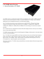
CT-10G-MC series is a complete and versatile solution for applications such as FTTx, CWDM, and carrier
Ethernet. By the diversified speeds of 10Gbps, our provides standalone CT-10G-MC series for different
applications and can be applied according to your ideal network topology.
Our CT-10G-MC series provides various interfaces such as 10GUTP, SFP+, XFP and CX4. All these
interfaces are developed to support the protocols such as 10GBase-T, 10GBase-EZR, 10GBase-ZR,
10GBase-ER, 10GBase-LR, 10GBase-SR and 10GBase-CX4, thus making your network more complete
and solid.
All CT-10G-MC series are equipped with real-time LEDs which display the status of each port, thus allowing
users to view network status easily.
CT-10G-MC series provides an easy-to-access Management Webpage, allowing users to view system status,
counters, and network statistics.
Also, CT-10G-MC series supports MIB Counter Report including counters such as Packet, Byte, Broadcast
packet, Pause Frame, Length: 64 Bytes, Length: 65-127 Bytes, Length: 128-255 Bytes, Length: 256-511
Bytes, Length: 512-1023 Bytes, Length: 1024-1518 Bytes, Unicast packet, Multicast packet, CRC Error,
IP Checksum Error , Under size packet, and Over size packet.
With various interfaces, CT-10G-MC series provides different conversions between fibers and copper wires in
10Gbps Ethernet.
6
1.2. Features, Key Advantages, and Main Applications of CT-10G-MC series
Features
Diversified interfaces including SFP+, RJ45, XFP and CX4
Supports 3R (Re-generation, Re-timing, Re-shaping) Performance, both in STM-64 & OC-192
Supports Jumbo Frame
Supports DDI (Digital Detection) functioned optical transceivers and overload protection
Support easy-to-use Management Webpage that allows users to view system status, counters,
and network statistics
Supports SNMP (Simple Network Management Protocol)
Supports Link Loss Forwarding
Key Advantages
Fast connection with multi-function
Provide reliable long-distance connection
Port supported: SFP+, RJ45, XFP and CX4
Small portable size case
Plug and play without extra configuration
Main Applications
Media converter for network backbone
Connection between fiber to copper or fiber to fiber 10Gbps Ethernet equipment
Can be applied in Telecommunication room, R&D laboratory, Data center, and etc.
7
1.3. CT-10G-MC series Functions Overview
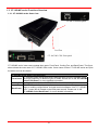
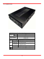
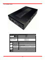
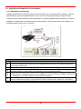
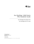
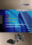
1.3.1. CT-10G-MC series Outer Case
CL-MC-CX4 back panel
Cool Fan
CT-10G-MC-CX4 Front panel
CT-10G-MC series’ outer case consists three parts: Front Panel, Cooling Fan, and Back Panel. The figure
above shows the outer case of CT-10G-MC-CX4 series. Outer cases of other CT-10G-MC series are quite
the same and can be related.
CT-10G-MC series Outer Case Overview
CT-10G-MC series comes with various different types of ports, providing media
Front Panel converting platforms for different types of media. Please see “1.3.2. CT-10G-MC
series Front Panel” for more detailed information.
Cooling
fan for ventilation. All CT-10G-MC series have cooling fans installed.
Cooling Fan
CT-10G-MC series’ back panels allow users to access their management web
pages or making configurations via hyper terminal softwares. Also, CT-10G-MC
Back Panel
series’ power jack is located on the back panel as well. Please see “1.3.3.
CT-10G-MC series Back Panel” for more detailed information.
8
1.3.2. CT-10G-MC series Front Panel
As mentioned in “1.3.1. CT-10G-MC series Outer Case”, CT-10G-MC series comes with various different
types of ports, providing media converting platforms for different types of media. Please see the sections
down below for more detailed information/specification for CT-10G-MC series.
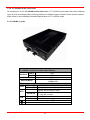
A. CT-10G-MC-1 series
CT-10G-MC-1 series Front Panel Specification
Port A
SFP+
Interface
Port B
SFP+
10Gbps
Data Transfer Rate
10GBase-LR
Ethernet Mode
10GBase-SR
LED Status
CT-10G-MC-1 series is power on.
Green ON
Power
Green OFF CT-10G-MC-1 series is power off.
CT-10G-MC-1 series is booting
Green ON
properly and is ready for tests.
SYS
Error occurred when booting
Yellow ON
CT-10G-MC-1 series.
Port A/B is connected.
Green ON
A/B
Green Blinking Port A/B is transmitting/receiving data.
▇
User-defined LED
▲
User-defined LED
9
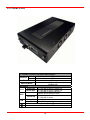
B. CT-10G-MC-2 series
CT-10G-MC-2 series Front Panel Specification
Port A
SFP+
Interface
XFP
Port B
10Gbps
Data Transfer Rate
10GBase-LR
Ethernet Mode
10GBase-SR
LED Status
CT-10G-MC-2 series is power on.
Green ON
Power
Green OFF CT-10G-MC-2 series is power off.
CT-10G-MC-2 series is booting
Green ON
properly and is ready for tests.
SYS
Error occurred when booting
Yellow ON
CT-10G-MC-2 series.
Port A/B is connected.
Green ON
A/B
Green Blinking Port A/B is transmitting/receiving data.
▇
User-defined LED
▲
User-defined LED
10
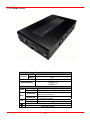
C. CT-10G-MC-3 series
CT-10G-MC-3 series Front Panel Specification
RJ45
Port A
Interface
Port B
SFP+
10Gbps
Data Transfer Rate
10GBase-LR
10GBase-SR
Ethernet Mode
10GBase-T
LED Status
CT-10G-MC-3 series is power on.
Green ON
Power
Green OFF CT-10G-MC-3 series is power off.
CT-10G-MC-3 series is booting properly
Green ON
and is ready for tests.
SYS
Error occurred when booting
Yellow ON
CT-10G-MC-3 series.
Port A/B is connected.
Green ON
A/B
Green Blinking Port A/B is transmitting/receiving data.
▇
User-defined LED
▲
User-defined LED
11
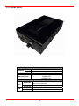
D. CT-10G-MC-4 series
CT-10G-MC-4 series Front Panel Specification
CX4
Port A
Interface
Port B
SFP+
10Gbps
Data Transfer Rate
10GBase-LR
10GBase-SR
Ethernet Mode
10GBase-CX4
LED Status
CT-10G-MC-4 series is booting properly
Green ON
and is ready for tests.
SYS
Error occurred when booting
Yellow ON
CT-10G-MC-4 series.
Port A/B is connected.
Green ON
A/B
Green Blinking Port A/B is transmitting/receiving data.
12
E. CT-10G-MC-5 series
CT-10G-MC-5 series Front Panel Specification
XFP
Port A
Interface
XFP
Port B
10Gbps
Data Transfer Rate
10GBase-LR
Ethernet Mode
10GBase-SR
LED Status
CT-10G-MC-5 series is power on.
Green ON
Power
Green OFF CT-10G-MC-5 series is power off.
CT-10G-MC-5 series is booting properly
Green ON
and is ready for tests.
SYS
Error occurred when booting
Yellow ON
CT-10G-MC-5 series.
Port A/B is connected.
Green ON
A/B
Green Blinking Port A/B is transmitting/receiving data.
▇
User-defined LED
▲
User-defined LED
13
F. CT-10G-MC-6 series
CT-10G-MC-6 series Front Panel Specification
RJ45
Port A
Interface
XFP
Port B
10 Gbps
Data Transfer Rate
1000Base-T
10GBase-LR
Ethernet Mode
10GBase-SR
LED Status
CT-10G-MC-6 series is power on.
Green ON
Power
Green OFF CT-10G-MC-6 series is power off.
CT-10G-MC-6 series is booting properly and
Green ON
is ready for tests.
SYS
Error occurred when booting CT-10G-MC-6
Yellow ON
series.
Port A/B is connected.
Green ON
A/B
Green Blinking Port A/B is transmitting/receiving data.
▇
User-defined LED
▲
User-defined LED
14
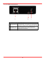
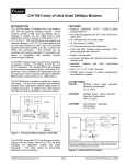
1.3.3. CT-10G-MC series Back Panel
A
B
C
CT-10G-MC series Back Panel Description
100 Mbps RJ45 Management Port for connecting
A Management Port CT-10G-MC series to a network, thus allowing users
to access CT-10G-MC series’ management web pages
2.5mm Phone Jack for connecting PC’s RS 232
B Diagnostic Port port, thus allowing users to make configurations
via hyper terminal softwares.
DC 12 V Power Jack
C
Power Jack
15
2. CT-10G-MC series Installation
As a media convertor platform, installing CT-10G-MC series is very easy and simple: all you have to do is to
plug the proper fiber/UTP cables into CT-10G-MC series’ ports like a general Ethernet switch without any extra
configurations. However, selecting the proper physical media and applications in your network
environment is crucial when installing CT-10G-MC series. Please see the sections down below for detailed
information regarding to physical media types and CT-10G-MC series application.
2.1. Choices of UTP Cable and Optical fiber
2.1.1. 10GBASE-T (Copper Wire)
10GBASE-T, or IEEE 802.3an-2006, is a standard released in 2006 to provide 10 gigabit/second
connections over unshielded or shielded twisted pair cables and over distances up to 100 meters (330 ft).
10GBASE-T cable infrastructure can also be used for 1000BASE-T, allowing a gradual upgrade from
1000BASE-T, and auto-negotiation to select which speed to use.
10GBASE-T Connectors
10GBASE-T uses 650 MHz versions of the venerable IEC 60603-7 8P8C (RJ-45) connectors, which is
already widely used in Ethernet.
10GBASE-T Cables
10GBASE-T works up to 55 m (180 ft) with existing Category 6 cabling. In order to allow deployment at
the usual 100 m (330 ft), the standard uses a new partitioned Category 6a cable specification, designed
to reduce crosstalk between UTP cables.
The table down below is a reference regarding to UTP cable categories.
UTP Cable Categories References
Provides performance of up to 100 MHz, and was frequently used on 100 Mbps Ethernet
Cat 5
networks. Cat 5 may not be suitable for 1000BASE-T gigabit Ethernet.
Provides performance of up to 100 MHz, and is frequently used for both 100 Mbps and
Cat 5e
Gigabit Ethernet networks.
Provides performance of up to 250 MHz, more than double of category 5 and 5e. It works up
Cat 6
to 55 m (180 ft) for 10Gbps Ethernet.
Provides performance of up to 500 MHz. It is suitable for
10GBASE-T and works up to 100 m (330 ft) for 10Gbps
Cat 6a Ethernet. All the cables mentioned above do not have
individually- shielded pairs as the picture here, including
Cat 6a.
This standard specifies four individually-shielded pairs (STP) inside an overall shield.
Cat 7 Designed for transmission at frequencies up to 600 MHz. It has better performance than Cat
6a.
16
2.1.2. 10GBASE-R (Optical Fiber)
10GBASE-R is 10Gbps Ethernet connection that based on IEEE802.3ae. It uses fiber as transmission
media with different specification of fiber, connector and transceiver. CT-10G-MC series uses two standards,
10GBASE-LR and 10GBASE-SR.
10GBASE-SR
10GBASE-SR ("Short Range") uses 64B/66B encoding and 850 nm wavelength lasers. It is designed to
support short distances over deployed multi-mode fiber cabling, it has a range of between 26 meters (85
ft) and 82 meters (270 ft) depending on cable type. It also supports 300 meters (980 ft) operation over
new, 50 μm 2000 MHzkm OM3 multi-mode fiber (MMF).
The transmitter can be implemented with a VCSEL (Vertical Cavity Surface Emitting Laser) which is low
cost and low power. MMF has the advantage of having lower cost connectors than SMF (single-mode
fiber) due to its wider core.
10GBASE-SR delivers the lowest cost, lowest power and smallest form factor optical modules.
10GBASE-LR
10GBASE-LR ("Long Range") is a Long Range Optical technology delivering serialized 10 gigabit
Ethernet over a laser with 1310 nm wavelength connection on single-mode fiber via IEEE 802.3 Clause
49 64B-66B Physical Coding Sub layer (PCS) using a line rate of 10.3125.
Single-mode optical cabling is used to interconnect transceivers at a distance spaced at 10 kilometers
(6.2 mi), but it can often reach distances of up to 25 kilometers (16 mi) with no data loss.
Fabry–Pérot lasers are commonly used in 10GBASE-LR optical modules. Fabry–Pérot lasers are more
expensive than VCSELs (mentioned above) but their high power and focused beam allow efficient
coupling into the small core of single mode fiber.
Fiber Specification
Fibers which support many propagation paths or transverse modes are called multi-mode fibers (MMF).
Fibers which can only support a single mode are called single-mode fibers (SMF). Multi-mode fibers
generally have a larger core diameter, and are used for short-distance communication links and for
applications where high power must be transmitted. Single-mode fibers are used for most
communication links longer than 200 meters.
Fiber Buffer/Jacket Color
Meaning
Yellow
Single-mode optical fiber, long distance connection
Orange
Multi-mode optical fiber, short distance connection
17
2.2. Connection of UTP Cable and Optical fiber
2.2.1. 10GBASE-T (Copper Wire)
10GBASE-T uses the same RJ45 connector that is the same as original 100M/1000Mbps Ethernet
network. Just plugging the RJ45 connector into the port of 10Gbps and it is ready to work. When
connected properly, the Link/ACT LED located under the RJ45 Port will be on accordingly. 10G UTP
need apply Cat6a or Cat7 cable.
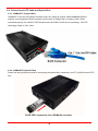
2.2.2. 10GBASE-R (Optical Fiber)
Please see the figure down below for connecting the optical fiber, transceiver, and CT-10G-MC series’ SFP+
Port.
PLUG SFP+ transceiver into 10G Media converter
18
Optical Fiber
As mentioned above, there are Single-mode and Multi-mode optical fiber. Both of them can be used for
CT-10G-MC series .
Fiber Connector
Optical fiber connector contains two ends of fibers and can attach
to SFP+ transceivers. There are two ports for one SFP+
transceiver: one fiber is for receiving and one fiber is for
transmitting. The picture here is called LC connector that can
attach to SFP+ transceiver.
Transceiver (Connector)
SFP+/XFP Transceivers can be plugged into CT-10G-MC series’ SFP+/XFP Ports. SFP+/XFP Transceivers
are active components that consume power from CT-10G-MC series and are capable of converting signals
between optical data flow and electronic data flow.
For different transmission purpose, the component inside SFP+ form factor can be 10BASE-SR, LR, ER,
ZR, EZR, mode.
19
2.3. Applications Examples for Your Network
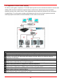
2.3.1. Application for University
10Gbps speed Ethernet connection may not be commonly seen in ordinary offices. However, network
administrators may have Gigabit Ethernet in their control rooms already. Getting 10Gbps Ethernet
connection from Internet Backbone and distributing it to different Gigabit Ethernet segment for different
buildings or organizations is practical and more cost-effective. Figure down below is an example of a
possible network structure for a university:
Descriptions
A Internet backbone from ISP.
The distance from the central office to the university might be long, and it is advised to construct the
B connection via single-mode optical fiber with 10BASE-LR mode, which can extend the distance
beyond tens of kilometers.
C CT-10G-MC series, which is located at the computer center of university.
After the conversions made by CT-10G-MC series, expensive equipments for
D
transmitting/receiving network data via optical fiber are not required anymore.
Full 10Gbps Ethernet switches may be exceeding your budget or not available. Some 1Gbps
E switches reserve a swappable slot for future upgrading. You can purchase a 10Gbps module with
one 10Gbps port for these switches to serve the same purpose.
Several 1Gbps connections can be distributed by the switches mentioned above to different
F
buildings inside the university by Cat 6a network cables (which can be extended to 100 meters).
G/H/I General switches with 1Gbps or 100Mbps ports can be connected here for the end-users.
20
2.3.2. Application for Online Game Company
For ISPs or online game companies, CT-10G-MC series provide a more economical solution for control room
cabling. ISP runs lots of customer's service such as e-mail servers, web servers or any co-located
network services in the control rooms. These equipments may not have the interface for the connection
of optical fibers. For online game company, administrators may have lots of online game servers that
need high-speed connections to Internet backbone in the control rooms as well.
Descriptions
A Internet client users
B Mass requests of the general public, coming from other ISPs through Internet.
The distance from other ISPs to the game company might be long, and it is advised to construct the
C connection via single-mode optical fiber with 10BASE-LR mode, which can extend the distance
beyond tens of kilometers.
D CT-10G-MC series, which is located at the control room of the game company.
After the conversions made by CT-10G-MC series, expensive equipments for transmitting/receiving
E
network data via optical fiber are not required anymore.
Depending on the network loading requirements, Ethernet Switch with full 10Gbps ports or partial
F
10Gbps/1Gbps ports should be configured for data flow distributions.
If that the bandwidth requirement of co-located mail servers for some companies is not heavy, you can
G
connect them to 1Gbps port of 10Gbps switch as shown in the figure above.
If the bandwidth requirement of online game servers is heavy, you can connect them to 10Gbps port of
H
10Gbps switch as shown in the figure above.
Different kinds of server with different applications are located side by side by connections from
I
10Gbps Ethernet Switch via inexpensive Cat.6 cable.
21
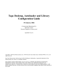
2.3.3. Application for Home Users
The figure down below is an example of how the FTTX architectures may vary regarding to distances
between the optical fiber and the end-users. Fiber to the x (FTTX) is a generic term for any network
architecture that uses optical fiber to replace all or part of the usual copper local loop used for
telecommunications. These four Technology are listed down below:
Fiber to the node / neighborhood (FTTN)
Fiber to the building (FTTB)
Fiber to the curb (FTTC) / Fiber to the kerb (FTTK) Fiber to the home (FTTH)
The building on the left is the central office. The building on the right is one of the buildings served by the
central office. The white or gray blocks represent separate rooms or office spaces within the same
building.
Descriptions
A ISP Central Office
B Network connection via optical fiber
C Installation of CT-10G-MC series for media conversion
Network connection via copper wire. It can be Cat 6a cable (under 300 meters) or telephone line via
D
xDSL (Technology such as VDSL provide high speed, short-range link are used often in FTTx service)
E Different rooms of homes or different compartments in the same building.
CT-10G-MC series can be located at any place that near or away from building, depending on the
F
service to home users.
22
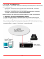
3. CT-10G-MC series Management
You can configure CT-10G-MC series’ settings and view statistics generated while performing media converting
with CT-10G-MC series by:
Connecting CT-10G-MC series and PC to the same network via an RJ45 cable, and accessing
CT-10G-MC series’ settings/statistics with PC’s web browser.
Connecting CT-10G-MC series and PC via a 2.5mm Phone Jack to RS232 cable, and accessing
CT-10G-MC series’ settings/statistics with HyperTerminal Softwares.
Please see the sections down below for more information regarding to CT-10G-MC series management.
3.1. Managing CT-10G-MC series with Management Webpage
CT-10G-MC series is embedded with a management webpage, and can be accessed by connecting
CT-10G-MC series’ Management Port to the network which your PC is connected to via an RJ45 cable.
Before accessing to CT-10G-MC series’configuration webpage with your PC’s web browser, please set the
network according CT-10G-MC series’default IP Address (192.168.1.8). The figure down below is an example
of network/PC settings for accessing CT-10G-MC series
23
management webpage.
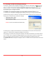
3.1.1. Accessing CT-10G-MC series Management Webpage
To access CT-10G-MC series’ management webpage, please open your web browser, and
type in CT-10G-MC series’ default IP address (192.168.1.8) in web browser’s URL field as
shown in the figure on the right side. If you’ve changed CT-10G-MC series’ IP address, please input
the IP address you’ve changed to instead.
CT-10G-MC series’ management webpage only supports Microsoft Internet Explorer ®, and
CT-10G-MC series’ management webpage might not display correctly if you’re using other web browser.
A window will pop up after you entering CT-10G-MC series’IP address. Please enter the User Name and
Password for CT-10G-MC series’ configuration webpage.
Default User Name: admin
Default Password: admin*
*Please note that the User Name and Password are case-sensitive.
RE-BOOT if you have any modification than Default setting
For safety issues, it is highly recommended that you should change the User name and Password when
logging to CT-10G-MC series’ management webpage for the first time.
After inputting CT-10G-MC series management webpage’s User Name and Password, you should be able to
see CT-10G-MC series’ management webpage displayed on your web browser as shown in the figure down
below. The following sections will illustrate CT-10G-MC series management webpage functions with
CT-10G-MC-XFP2 series. Management webpage for other CT-10G-MC series are quite the same and can be
related.
24
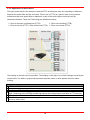
3.1.2. CT-10G-MC series Management Webpage – Overview
CT-10G-MC series
A
Management Webpage Overview
This field displays the port status of your CT-10G-MC series. You can
view the media type of a specific port by moving the mouse to it.
If CT-10G-MC series’ port is not connected, the Port
Status icon will show as the figure on the left.
Port Status
If CT-10G-MC series’ port is connected, the Port Status
icon will show as the figure on the left.
Also, to view the counter report of a specific port, just click on the port.
The Setting Options contains options for CT-10G-MC series’ettings,
information, and statistics, which can be divided into:
System: You can view system information here in this field.
Management: This option allows you to make settings such as
CT-10G-MC series’IP address, SNMP, or user accounts.
B
Setting Options
Counter: You can view CT-10G-MC series’ counter reports with
this option.
Maintenance: This option allows you to save system settings,
reboot CT-10G-MC series, and reset all CT-10G-MC series’
settings to default value.
This field displays the model name of your CT-10G-MC series.
C
Model Name
The Main Display Screen displays the system information, network
D Main Display Screen
tapping statistics, and detail configuration options.
25
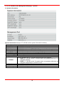
3.1.3. CT-10G-MC series Management Webpage – System
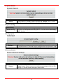
A. System Information
System Information displays CT-10G-MC series’ system information including:
System Information
S/N
MAC Address
FPGA Version
Firmware Version
Port A SFP Factory
Port B SFP Factory
SFP Wavelength
Management Port
IP Mode
IP Address
Subnet Mask
Gateway
CT-10G-MC series’ serial number.
CT-10G-MC series’ MAC address.
CT-10G-MC series’ current FPGA (Field-Programmable Gate Array) version.
CT-10G-MC series’ current firmware version.
The manufacturer of the transceiver plugged in Port A.
The manufacturer of the transceiver plugged in Port B.
The wavelength of Port A/B.
This field displays how CT-10G-MC series acquires its IP address.
Static: CT-10G-MC series’ IP, subnet mask, and gateway addresses are
assigned manually.
DHCP: CT-10G-MC series’ IP, subnet mask, and gateway addresses are
assigned automatically by a DHCP server.
CT-10G-MC series’ IP address.
CT-10G-MC series’ subnet mask.
CT-10G-MC series’ gateway address.
26
3.1.3. CT-10G-MC series Management Webpage – Management
There are 3 options available for Management, which includes:
IP Configuration: Allows you to set how CT-10G-MC series will acquire its IP, subnet mask, and
gateway addresses. Also, you could input these addresses manually here.
User Settings: Allows you to change CT-10G-MC series configuration webpage User Name and
Password.
System Configuration: You can set System Contact, System Location, and System Name
here.
SNMP Setting: You can make SNMP (Simple Network Management Protocol) settings here.
Please see the sections for detail descriptions about settings available in Management:
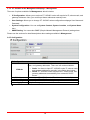
A. IP Configuration
IP Configuration
You can choose how CT-10G-MC series acquires its IP, subnet
mask, and gateway addresses. There are two modes available:
IP Mode
IP Address
Subnet Mask
Gateway
Apply
Static: You have to input CT-10G-MC series’ IP, subnet mask,
and gateway addresses manually in the fields down below.
DHCP: CT-10G-MC series acquires its IP, subnet mask, and
gateway addresses automatically from network’s DHCP
server.
You can input CT-10G-MC series’ IP address here in this field.
You can input CT-10G-MC series’ subnet mask here in this field.
You can input CT-10G-MC series’ gateway address here in this field.
Apply the changes you’ve made here.
*Note: The default IP address for CT-10G-MC series is 192.168.1.8.
27
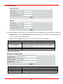
B. User Settings
For issues regarding to system security, CT-10G-MC series has 2 different user security levels, which are:
Administrator: User with Administrator privilege can change CT-10G-MC series system settings
and view system information/statistics.
Guest: User with Guest privilege can only view system information/statistics.
User Settings for Administrator/Guest
Input the user name here in this field.
User Name
Input the password here in this field. Please note that the
password must contain at least 5 alphanumeric characters
New Password
and is case sensitive.
Confirm New Password Please input the password here again for confirmation.
Apply the changes you’ve made here.
Apply
C. System Configuration
System Configuration
System Contact
System Location
System Name
Apply
Input the contact information for CT-10G-MC series here in this field.
Input the system’s location for CT-10G-MC series here in this field.
Input the alias for CT-10G-MC series here in this field.
Apply the changes you’ve made here.
28
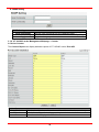
D. SNMP Setting
SNMP Setting
Read Community
Write Community
Apply
Input the user name that has only READ privilege.
Input the user name that has both WRITE and READ privileges.
Apply the changes you’ve made here.
3.1.4. CT-10G-MC series Management Webpage – Counter
A. Device Counter
The Counter Report can display statistics reports of CT-10G-MC series’ Port A/B.
Device Counter
Auto Refresh
Refresh
Clear
Click the check box here allows the statistics table to refresh automatically.
Refresh the configuration webpage and update the latest statistics.
Clear all statistics displayed in the table.
29
3.1.5. CT-10G-MC series Management Webpage – Maintenance
Four options are available in the Maintenance configuration webpage: Save Changes, System Reboot,
Factory Defaults, and Logout.
A. Save Changes
Save Changes
Save
If you don’t save the setting you’ve made via CT-10G-MC series’ configuration
webpage, all settings will be erased after rebooting CT-10G-MC series. Please
click the “Save” button to save the settings to CT-10G-MC series’ NV-RAM.
B. Update F/W (Firmware)
Update F/W (Firmware)
Click the Browse… button to choose the firmware file you would like to
Browse…
upgrade. CT-10G-MC series’ firmware files are in the format of “*.bin”.
Click this button to start upgrading CT-10G-MC series’ firmware.
Send
C Update FPGA
Update FPGA
Browse…
Send
Click the Browse… button to choose the FPGA file you would like to upgrade.
CT-10G-MC series’ FPGA files are in the format of “*.bin”.
Click this button to start upgrading CT-10G-MC series’ FPGA.
30
D. System Reboot
System Reboot
Reboot
You can reboot CT-10G-MC series by clicking the “Reboot” button. Please
note that all unsaved settings will be lost after system reboot.
E. System Config
System Config
System Config
Click System Config to save all CT-10G-MC series’ current settings into a
“*.cfg” file. You can upload this config file to CT-10G-MC series with Config
Upload function.
F. Config Upload
Config Upload
Browse…
Send
Click the Browse… button to choose the config file you would like to upload to
CT-10G-MC series. CT-10G-MC series’ config files are in the format of “*.cfg”.
Click this button to start uploading CT-10G-MC series’ config file.
G. Factory Defaults
Factory Defaults
Restore
You can set all CT-10G-MC series’ settings to the default value by clicking the
“Restore” button. Please note that all unsaved data/settings will be lost after
restoring CT-10G-MC series’ settings to default value.
31
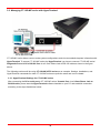
3.2. Managing CT-10G-MC series with HyperTerminal
CT-10G-MC series allows users to make system configurations and view test statistics/system information with
HyperTerminal. To access CT-10G-MC series via HyperTerminal, you have to connect CT-10G-MC series’
Diagnostic Port with PC’s RS-232 Port via a 2.5mm Phone Jack to RS-232 cable as shown in the figure
above.
The following sections will be using CT-10G-MC-XFP2 series as an example. Settings, installations, and
HyperTerminal commands for other CT-10G-MC series are quite the same and can be related.
3.3.1. HyperTerminal Settings for CT-10G-MC series
After connecting the PC’s serial port to CT-10G-MC series’ Console Port via a 2.5mm Phone Jack to
RS-232 cable, please start the HyperTerminal software installed on your PC and establish connection
according to the steps listed down below.
32
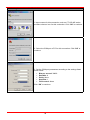
Establishing Connection with CT-10G-MC series
1. Input a name for this connection, such as CT-10G-MC series,
and also select an icon for this connection. Click “OK” to continue.
2. Select the COM port of PC for this connection. Click “OK” to
continue.
3. Set the COM port parameters according to the settings listed
down below:
Bits per second: 38400
Data bits: 8
Parity: None
Stop bits: 1
Flow control: None
Click “OK” to continue.
33
Establishing Connection with CT-10G-MC series
Click the “Enter” key on your keyboard to start setting CT-10G-MC series via HyperTerminal. To log in,
please type CT-10G-MC series’ user name and password:
Default User Name: admin
Default Password: admin (Both the User Name and Password are case-sensitive.)
If you change CT-10G-MC series’ user name and password with CT-10G-MC series’ configuration
webpage, please log in with the new user name and password here.
34
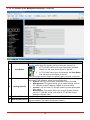
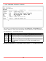
3.3.2. CT-10G-MC series HyperTerminal Commands
After logging in CT-10G-MC series via HyperTerminal, a CT-10G-MC series Command Menu will be
displayed, showing CT-10G-MC series’ HyperTerminal commands. Please see the table down below for
brief descriptions of CT-10G-MC series commands:
Command Alias
Command Description
The system command allows you to view CT-10G-MC series’ system information,
system
sys
make system configurations, and upgrade CT-10G-MC series’ firmware/FPGA.
counter
cnt The counter command allows you to view CT-10G-MC series’ counter information.
The ip command allows you to view CT-10G-MC series’ current IP settings or
ip
ip
configure these settings.
cls
cls The cls command allows you to clear HyperTerminal screen.
The logout command allows you to log out. For security issues, it is
logout logout recommended that you should log out if you’re not using the HyperTerminal
anymore.
Please see sections down below for more detailed information regarding to CT-10G-MC series’ command.
35
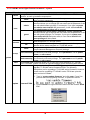
A. CT-10G-MC series HyperTerminal Command – system
Command Descriptions – system
The system show allows you to view CT-10G-MC series’ PCB/firmware/FPGA
show
versions, as well as hardware temperature.
The system user show command allows you to view the current
show
users and their passwords.
The system user admin [name | password] <name | password>
command allows you to change the user name and its password of the
admin
user with administrator privilege. For example, if you type in system
user admin name test123 and press enter, a user named test123
user
with administrator privilege will be created.
The system user guest [name | password] <name | password>
command allows you to change the user name and its password of the
user with guest privilege. For example, if you type in system user
guest
guest name test123 and press enter, a user named test123 with
guest privilege will be created.
The system devname show command allows you to view the device
show
name assigned to CT-10G-MC series.
devname
The system devname set [device name] command allows you to
set
view the device name assigned to CT-10G-MC series.
The system snmp show command will show the current SNMP
show
(Simple Network Management Protocol) settings.
The system snmp writecommunity <parameter> allows you to set
writecommunity the community with write privilege. The <parameter> can be public,
snmp
private, or user names.
The system snmp readcommunity <parameter> allows you to set
system
readcommunity the community with read privilege. The <parameter> can be public,
private, or user names.
The system save command allows you to save the current settings to CT-10G-MC
save
series’ NV-RAM. Please note that all unsaved settings will be lost after system reboot.
The system update [firmware/FPGA] commands allow you to
upgrade CT-10G-MC series’ firmware/FPGA. The following
descriptions are for upgrading CT-10G-MC series’ firmware. However,
proced ures for upgrading CT-10G-MC series’ FPGA are quite the
same and can be related.
1. Type in “system update firmware” and click enter. Press Y to
proceed and start upgrading firmware, or press N to cancel.
update
firmware/FPGA
2. Press Transfer on HyperTerminal’s menu bar and choose “Send
File”.
36
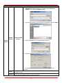
Command Descriptions – system
3. A Send File window will pop up. Please set the Protocol to
Xmodem, and click the Browse button.
4. Choose the firmware you would like to upgrade to and click Open.
update firmware/FPGA
(Contd.)
(Contd.)
system
(Contd.)
5. Click the Send button to start sending firmware.
6. System is sending firmware to CT-10G-MC series.
7. CT-10G-MC series will reboot when finishing upgrading its
firmware.
The system reset command allows you to reset all CT-10G-MC series settings back to
reset
the default values.
The system reboot command allows you to reboot CT-10G-MC series. Please note
reboot
that all unsaved settings will be lost after rebooting.
37
B. CT-10G-MC series HyperTerminal Command – counter
Command Descriptions – counter
The counter show command allows you to view all CT-10G-MC series’ counter report.
show
counter
C: Press C to clear all counters.
S: Press S to stop/start refreshing counters.
P: Press P to switch pages. CT-10G-MC series’ counter report has 2 pages.
Esc: Press the Esc key to exit CT-10G-MC series’ counter report.
0 Clear all counter reports of CT-10G-MC series’ Port A.
1 Clear all counter reports of CT-10G-MC series’ Port B.
all Clear all counter reports of CT-10G-MC series’ Port A and Port B.
The refreshtime show command allows you to view the refresh time for the
show
report.
refreshtime
The refreshtime set command allows you to set the refresh time (in seconds)
set
for the report.
clear
C. CT-10G-MC series HyperTerminal Command – ip
Command Descriptions – ip
show The ip show command allows you to view information of CT-10G-MC series’ IP configuration.
status The ip status command allows you to view information of CT-10G-MC series’ IP status.
The ip mode dhcp command allows you to set CT-10G-MC series’ IP acquiring mode
dhcp
to DHCP, allowing CT-10G-MC series to acquire IP automatically from DHCP server.
mode
The ip mode static command allows you to set CT-10G-MC series’ IP acquiring
static
mode to Static, allowing you to set IP/Subnet Mask/Gateway IP manually.
The ip address <IP Address> command allows you to set CT-10G-MC series’ IP address.
ip
address* For example, to set CT-10G-MC series’ IP address to 192.168.1.20, please input the
command “ip address 192.168.1.20”.
The ip mask <Subnet Mask Address> command allows you to set CT-10G-MC series’
mask* subnet mask address. For example, to set CT-10G-MC series’ subnet mask address to
255.255.255.0, please input the command “ip mask 255.255.255.0”.
The ip gateway <Gateway Address> command allows you to set CT-10G-MC series’
gateway* gateway address. For example, to set CT-10G-MC series’ subnet gateway address to
192.168.1.254, please input the command “ip gateway 192.168.1.254”.
*CT-10G-MC series’ default IP address/subnet mask/default gateway are 192.168.1.8/255.255.255.0/192.168.1.1
38
D. CT-10G-MC series HyperTerminal Command – cls
Command Descriptions – cls
cls The cls command allows you to clear HyperTerminal screen.
E. CT-10G-MC series HyperTerminal Command – logout
Command Descriptions – logout
logout The logout command allows you to log out of CT-10G-MC series’ HyperTerminal configuration session.
39
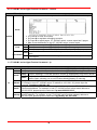
4. CT-10G-MC series General Specifications
System Control
System Control
Transceiver
Power ON/OFF
Media Type
Selectable Auto/Force
Device Status Report
Information
Status Report Link Status
Temperature Detection
MIB Counter Report *
Packet
Broadcast packet
Length: 64 Bytes
Length: 128-255 Bytes
Counter Report
Length: 512-1023 Bytes
Unicast packet
CRC Error
Under size packet
Hardware
Temperature Operating: 0oC ~ 40oC (32oF ~ 104oF)
Humidity
Operating: 0% ~ 85% RH
(non-condensing)
Dimension
Link
Connection Mode: Slave/Segment
Upgrade (F/W, FPGA)
System
Module
Detection
Module Detection
Transceiver overloading
Fiber
Byte
Pause
Frame
Length: 65-127 Bytes
Length: 256-511 Bytes
Length: 1024-1518 Bytes
Multicast packet
IP Checksum Error *
Over size packet
Storage:
0oC ~ 50oC (32oF ~ 122oF)
Storage:
0% ~ 85% RH
147 mm x 89 mm x 28 mm
40