1
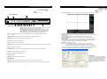
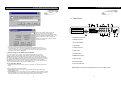
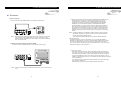
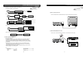
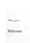
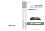
Thank you for purchasing our product.
Please read this User s Manual before
using the product.
STAND-ALONE DVMR
4 Channel Digital Video Multiplex Recorder
User Manual
STAND-ALONE DVMR
VER 2.0
The most stable and reliable real stand-alone Digital Video Multiplex Recorder
ALL ABOUT IMAGE RECOGNITION & PROCESSING
ALL ABOUT IMAGE RECOGNITION & PROCESSING
ALL ABOUT IMAGE RECOGNITION & PROCESSING
SAFETY PRECAUTIONS
CAUTION
RISK OF ELECTRIC
SHOCK. DO NOT OPEN!
CAUTION : TO REDUCE THE RISK OF ELECTRICAL SHOCK, DO NOT OPEN COVERS.
NO USER SERVICEABLE PARTS INSIDE. REFER SERVICING TO QUALIFIED
SERVICE PERSONNEL.
This label may appear on the bottom of the unit due to space limitations.
The lightning flash with an arrowhead symbol within an equilateral triangle is intended
to alert the user to the presence of uninsulated “ dangerous voltage” within the
product’s enclosure that may be of sufficient magnitude to constitute a risk of electric
shock to persons.
The exclamation point within an equilateral triangle is intended to alert the user to
presence of important operating and maintenance (Servicing) instructions in the
literature accompanying the appliance.
WARNING : TO PREVENT FIRE OR SHOCK HAZARD, DO NOT EXPOSE UNITS NOT
SPECIFICALLY DESIGNED FOR OUTDOOR USE TO RAIN OR MOISTURE.
Attention: installation should be performed by qualified service Personnel only in
accordance with the National Electrical Code or applicable local codes.
Power Disconnect. Units with or without ON-OFF switches have power supplied to
the unit whenever the power cord is inserted into the power source ; however, the unit
is operational only when the ON-OFF switch is in the ON position. The power cord is
the main power disconnect for all unites.
ALL ABOUT IMAGE RECOGNITION & PROCESSING
ALL ABOUT IMAGE RECOGNITION & PROCESSING
ALL ABOUT IMAGE RECOGNITION & PROCESSING
7. Manual for
Remote viewer
software
FCC INFORMATION
⑨ Command button : We have 3 different buttons that are, save, print, and event.
a) Save
During searching recorded pictures, you can save pictures one by one in the folder in
client PC by pressing save button. File name automatically designated shall be date
and time when selected picture was recorded.
b) Print
During searching recorded pictures, you can print picture, one by one, you see.
c) Event
Press event button to see alarm list saved in DVMR unit, and you can search recorded
pictures based on event list by clicking any one of list.
d) Record
This button enables you to download pictures while you search recorded pictures for a
time duration (Record Duration) you already set in SYSTEM SETTING. While you
search recorded pictures, press Record button and you can save series of pictures for
Record Duration in avi format. If you set Record Duration at 30 sec, our client program
download pictures in avi format for 30 sec and save in the file name of Year-Month-DayHour-Minute-Second, and continue to download and save again after 30 seconds, and
so on. Every 30 seconds, it creates file in the name of Year-Month-Day-Hour-MinuteSecond until you press Stop button or Record button again. Then you can see using
Media Player later or you can put those pictures on CD or on other type of storage media
to show somebody who are in other place.
Size of file downloaded for 30 sec, for example, shall be 100MB, more or less,
depending on pictures taken, and we recommend you to download and save on your
computer whenever it is necessary, and delete those files if it is not necessary to save
for a long time, to take care of storage space of hard disk drive in your computer.
⑩ Calendar : You can select date and time to search pictures recorded at selected time
and date. You can refer to start and end of recording in ⑦.
Notice : From time to time, connection shall be cut unexpectedly due to conditions of network line. Whenever it is cut,
quit search window by pressing power switch(①), and then press connect button in live-view window and scan button
to enter into search window again, to continue searching.
Notice : Compatibility of Remote Viewer Software with different kinds of operating systems and PC hardware may
not be simply specified due to the characteristics of network that it is much related with not only PC hardware and
operating system but also other software installed on the client PC and conditions of network(internet) line. Basically,
Argus’ Remote Viewer Software is compatible with typical Windows operating system from Windows 98 to Windows
XP.
Notice : To see continuous live view, we recommend not to select motion recording in RECORD SETUP menu of
DVMR. If it is set at motion recording in SETUP menu of DVMR, image transmission is done only there is motions
detected.
Notice : While you search recorded data using client software in client PC, DVMR unit to which you access via IP
network is in playback mode, and no recording is done as far as you search recorded data. However, while you are in
connection with DVMR unit via IP network for live view, DVMR unit continues to record but at a little lowered
recording rate.
Therefore we recommend you to DVMR unit only when it is necessary.
39
A CLASS A computing device subject to certification by the Commission shall be identified pursuant to
par.2.925 et Seq of the chapter. In addition, the label shall include the following statement:
This device complies with Part 15 of the FCC Rules.
Operation is subject to the following two conditions:
(1)This device may not cause harmful interference, and
(2)This device must accept any interference received,
including interference that may cause undesired operation.
Where a device is constructed in two or more sections connected by wires and marketed together, the
statement specified in this Section is required to be affixed only to the main control unit.
The users manual or instruction manual for the EUT shall contain the following statement or eqivalent.
Caution : Changes or Modifications not expressly approved by the party responsible for compliance could
void the users authority to operate the equipment.
If the EUT requires accessories such as special shielded cables and/or connectors to enable compliance
with emission limits, the instruction manual for the EUT shall include appropriate instructions on the first
page of the text concerned with the installation of the device that these special accessories must be used
with the device. It is the responsibility of the user to use the needed special accessories supplied with the
equipment.
For a CLASS A digital device or peripheral, the instructions furnished the user shall include the following or
similar statement placed in a prominent location in the text of the manual.
Note : This equipment has been tested and found to comply with the limits for a CLASS a digital device,
pursuant to Part 15 of FCC Rules. These limits are designed to provide reasonable protection against
harmful interference when the equipment is operated in a commercial environment. This equipment
generates, uses and can radiate radio frequency energy and, if not installed and used in accordance with
the instruction manual, may cause harmful interference to radio communications. Operation of the this
equipment in a residential area is likely to cause harmful interference in which case the user will be required
to correct the interference at his own expense.
ALL ABOUT IMAGE RECOGNITION & PROCESSING
ALL ABOUT IMAGE RECOGNITION & PROCESSING
7. Manual for
Remote viewer
software
Function of each button in search window :
Table of Contents
1.About this document
2
2. Before reading this document
2
3. Unit Description
3
1) Front Panel
2) Rear Panel
3
4
4. Installation
5
5. Operation
9
1) Log-in
2) Record
3) Play
4) Setting
1 Basic Operation
2 DISPLAY SETUP
3 CAMERA SETUP
4 TIME/DATE SETUP
5 ALARM/MOTION SETUP
6 RECORD SETUP
7 TCP/IP SETUP
8 MISCELLANEOUS SETUP
9
10
13
15
15
16
17
19
20
23
24
25
① Power switch : Press power switch to quit.
② Full screen button : Press full screen button to search recorded picture channel by
channel in full screen.
③ Quad button : Press Quad button to search recorded pictures in quad screen, 4 pictures
from 4 channels at the same time.
④ Enlargement scale : You can adjust size by pressing or button and you will see
separate picture to be shown in enlargement window(⑦). By increasing or decreasing
size of enlargement scale, you will see picture to be shown in enlargement window shall
be increased or decreased.
Further you can drag enlargement scale you adjusted to the position to see enlarged
picture of corresponding part.
⑤ Channel selection button : Press any one from 1 to 4 to see picture of corresponding
channel, if you first chose full screen button(②).
Time displayed in green color is the time picture recorded.
⑥ Time selection button : You can set time to search pictures recorded at set time by
dragging vertical line to the left or right. See time to be displayed on the left(⑤) in green
color and find an exact location for the time from which you want to search.
⑦ Start and end of recording : It shows time from which recording started and recording
ended. Further it show time from which search will start.
⑧ Search operation button : You can search recorded data using various buttons useful
for searching effectively as follows.
Bottom row
Upper row
: Move to previous hour (on the hour)
: Play fast backward
(Speed set in SYSTEM SETTING (5-⑦) )
: Play backward(x1)
: Pause/Reverse play in set speed
: Stop
: Pause/Play in set speed
: Play forward (x1)
: Play fast forward
: Move to next hour (on the hour)
(Speed set in SYSTEM SETTING (5- ⑦) )
6. Specification & Configuration
1) SPECIFICATIONS
2) Stand alone DVMR
3) RS-232C Hex-codes table
4) Arrangement RS-232C pin
7. Manual for Remote viewer software
29
29
30
30
31
32
Speed of playback according to scan rate set in 5-⑦-b).
Scan rate set in 5-⑦-b)
or
1x
1x
1x
2x
1x
2x
4x
1x
4x
8x
1x
8x
16x
1x
16x
32x
1x
32x
64x
1x
60x
Maximum playback speed of DVMR is 60x.
1
or
38
ALL ABOUT IMAGE RECOGNITION & PROCESSING
ALL ABOUT IMAGE RECOGNITION & PROCESSING
7. Manual for
Remote viewer
software
1. About this document
Speed of playback in DVMR unit according to scan rate set in 4-7-b).
Scan rate set in 4-7-b)
or
or
1x
2x
4x
8x
16x
32x
64x
1x
1x
1x
1x
1x
1x
1x
1x
2x
4x
8x
16x
30x
60x
Before installing stand alone DVMR, be sure to thoroughly review and follow the instructions in this
User’s Manual. Pay particular attention to the parts those are marked NOTICE.
Also, when connecting with external application, first turn the power OFF and follow manual
instruction for appropriate installation.
2. Before reading this document
Maximum playback speed of DVMR is 60x.
10 : Command button.
We have 3 different buttons, that are, save, print, and event, and those buttons work only when stop
button is pressed.
a)Save
During searching recorded pictures, you can save pictures one by one in the folder in client PC by
pressing save button. Press Save button while you see recorded picture, and picture you selected by
pressing Save button shall be save on the folder you already assigned under the file name of year-monthday-hour-minute-second in jpg format.
b)Print
During searching recorded pictures, you can print picture, one by one, you see, by pressing Print button.
c)Event
Press event button to see alarm list saved in DVMR unit, and you can search recorded pictures based on
event list by clicking any one of list.
11 : Calendar.
You can select date and time to search pictures recorded at selected time and date. You can refer to start
and end of recording in 7.
Notice : From time to time, connection shall be cut unexpectedly due to conditions of network line.
Whenever it is cut, quit search window by pressing power switch(1), and then press connect button in liveview window and scan button to enter into search window again, to continue searching.
Notice : Compatibility of Remote Viewer Software with different kinds of operating systems and PC
hardware may not be simply specified due to the characteristics of network that it is much related with not
only PC hardware and operating system but also other software installed on the client PC and conditions
of network(internet) line. Basically, Remote Viewer Software is compatible with typical Windows operating
system from Windows 98 to Windows XP.
Notice : To see continuous live view, we recommend not to select motion recording in RECORD SETUP
menu of DVMR. If it is set at motion recording in SETUP menu of DVMR, image transmission is done only
there is motions detected.
Notice : While you search recorded data using client software in client PC, DVMR unit to which you access
via IP network is in playback mode, and no recording is done as far as you search recorded data.
However, while you are in connection with DVMR unit via IP network for live view, DVMR unit continues to
record but at a little lowered recording rate. Therefore we recommend you to access to DVMR unit only
when it is necessary.
37
1. This document is intended for both the administrator and users of stand alone DVMR Model.
2. This manual contains information for configuring, managing and using stand alone DVMR Model.
3. To prevent fire or electrical shock, do not expose the product to heat or moisture
4. Be sure to read this manual before using stand alone DVMR Model.
5. For questions and technical assistance of this product, contact your local dealer.
Strong recommendation on installation of the DVMR unit
1. Check electricity at the place you want to install the DVMR unit is stable and meets our
electricity requirements.
Unstable electricity will cause malfunction of the unit or give critical damage to the unit.
2. Several chips on the main board of the DVMR unit and hard disk drive inside the unit generate
heat, and it must be properly discharged.
Do not put any objects just beside exhaust port(fan) on the left side of the unit and do not close
up an opening (fresh air in-take) on the right side of the unit..
3. Put the DVMR unit at well-ventilated place and do not put heat-generating objects on the unit.
When it is installed inside 19 inch mounting rack together with other devices, please check builtin ventilation fan of the rack is properly running.
2
ALL ABOUT IMAGE RECOGNITION & PROCESSING
ALL ABOUT IMAGE RECOGNITION & PROCESSING
7. Manual for
Remote viewer
software
3. Unit Description
③ Disconnect button : Press disconnect button to cut connection to DVMR unit via IP network.
1. Front Panel
1
POWER
1
6
13
OVERWRITE
RECORD
PLAY
MENU
SETUP
2
1
PLAY
MODE
3
PIP
P/T
ENTER
2
3
4
FRZ
SEQ
ZOOM
MARK
4
5
7
6
SPEED
8
9
10 11
12
14
1. POWER SWITCH WITH LED : DC power switch with LED
Before you turn off DC power switch off, we strongly recommend you to press
[MENU] button first to make HDD not in writing process.
Generally speaking, cutting power to system may cause trouble in DVMR
system or damage to HDD if HDD is in writing process, and we ask you to
press [MENU] button first to protect HDD from being damaged or system
failure before you press DC power switch off in practical operation.
2. MENU : Used when changing the menu of SYSTEM SETUP. If you press [MENU] button, recording is
stopped.
3. PLAY/ENTER : Starts playback, and in some functions, it is used as the SELECT key.
4. MODE : Changes to quarterly split screen or Full display screen.
5. P/T : Manages PAN/TILT CONTROLLER.
6. 1,2,3,4 : Chooses each indicated camera.
7. PIP/MARK : Assigns PIP (Picture in picture) or MARK IMAGE to protect selected image from being overwritten.
8. FRZ : : Display screen is paused.
7
8
2
3
4
5
④ Screen division button : You can select to see pictures of any single channel or
4channels at the same time. You can select channel number from 1 to 4 to see pictures of
selected channel.
If you selected 4, you swill see channel number from 1 to 4 are all activated.
⑤ Channel number button : You can select channel number to see live pictures from
selected channel.
⑥ Status window : It shows Date and Time. Further it displays “Connection established”
and a circular fan on the left bottom is rotating when connection button is activated, or
“Waiting for connection” when disconnection button is activated
⑦ Set button : 3 different set buttons
a) Rotate : Press rotate button to see live pictures from channel 1 to 4 in rotation.
Screen division must be set at 1 to see live pictures one after another in
rotation. Speed of rotation shall be as per settings of circular monitoring interval.
b) Setting : It is in the middle of 3 buttons. Press this button to input IP Address and others
and to set circular monitoring interval and scan rate, as following dialog box.
9. SEQ/SPEED : The display screen automatically rotates, and assigns playback speed and direction.
10. ZOOM : Enlarges the display screen by 200%
11. Remote Controller Sensor Input Window
12. Direction button
CONNECTION :
- On the LABE column, you are requested to
input name of 4 ch DVMR units, in case you
want to access to any one DVMR unit among
more than a unit. You can save many IP
information in Configurations Window and
select name of DVMR unit to which you want
to access.
13. LED Lamps : Represent status of operation
14. CD-RW DRIVE
NOTICE : If the Input window (IR receiver) is covered, the remote controller may not work.
NOTICE : If several buttons are simultaneously or incorrectly pressed, the system may not function properly.
3
36
ALL ABOUT IMAGE RECOGNITION & PROCESSING
ALL ABOUT IMAGE RECOGNITION & PROCESSING
7. Manual for
Remote viewer
software
3.Unit Description
2. Rear Panel
2
When winipcfg launches, you’ll get a window like this one.
CAUTION
RS485 RELAY
RISK OF ELECT RIC
SHOCK. DO NOT OPEN!
CAUTION : TO REDUCE THE RISK OF ELECTRICAL SHOCK, DO NOT OPEN COVERS.
NO USER SERVICEABLE PARTS INSID E. REFER SERVICING T O QUALIFIED
SERVICE PERSONNEL.
RS-232C
3
7
9
ALARM
D D C N N G D D D D
-- + O C O N 4 3 2 1 ETHERNET
D
M
CH1
CH2
CH3
CH4
VCR
V
G
A
DC 12V
WARNNIG : TO PREVENT FIAE OR SHOCK HAZARD, DO NOT EXPOSE UNITS NOT
SPECIFICALLY DESIGNED FOR OUTDOOR USE TO RAIN OR MOISTURE
Now, hit the "Release" button and then hit
"Renew". If all goes well, you'll get new
information, and it is for your DVMR unit. Write
down this information on separate paper
and
input IP Address, Subnet Mask, and Default
Gateway into your DVMR to which you want to
access via IP network.
5
4
MONITOR
LOOP
1
6
8
1. RS-232C Port Connection
2. PAN/TILT Controller
3. Sensor Input/Output
4. LAN (TCP/IP)
b) Confirm if IP Address is working by executing pingtest
Execute pingtest with IP Address which you assigned to DVMR unit, check if it is
successful before you try to access to DVMR unit via IP network. If it is not successful,
you may not be able to access to DVMR unit via IP network, and we recommend you to
get help from your network administrator.
4. Insertion of logo in live window and scan window
You can insert logo of your company in live window and scan window, if you want.
When you install our client program, it automatically create folder named logo under
DVMRRemoteViewer folder. Prepare logo to be inserted in live window in the resolution of
85x55 in bmp format and in resolution of 165x65 in bmp format, respectively, and put them in
logo folder under DVMRRemoteViewer folder with name of blogo (to be shown in live window)
and slogo (to be shown in scan window).These logos will be shown on the right side of
POWER switch in live window and scan window, respectively. if you do not assign blogo and
slogo, no logo will be shown on the right side of POWER switch.
5. Live view via IP network
5. Camera Connection
6. LOOP Output
7. VCR Connection
8. MONITOR Connection
9. VGA Connection
10. S-VHS Connection
11. D/C Power Connection
Click Remote Viewer icon to view live pictures via IP network. You will see then following
window.
Function of each button in live-view window :
① Power switch : Press power switch to quit. Before press power switch button, press
disconnect button first.
② Connect button : Press connect button to connect to DVMR unit via IP network to see live
pictures of DVMR unit. You will see the same live pictures, which are displayed on monitor
of DVMR unit with a certain time delay depending on transfer rate of IP network.
35
NOTICE : When connecting with other applications, be sure to turn off the system.
4
10
11
ALL ABOUT IMAGE RECOGNITION & PROCESSING
ALL ABOUT IMAGE RECOGNITION & PROCESSING
7. Manual for
Remote viewer
software
4. Installation
▶ Procedure
1) Camera Connection
c) When it arrives at DHCP SETUP, it first display “SEARCHING” until DVMR unit gets
IP information and connects to the network, and then finally changes to “OK”.
If DHCP SETUP is completed and “OK” is displayed, DVMR unit successfully
connected to the network. Then enter into SYSTEM SETUP/ TCPIP SETUP/IP
ADDRESS. You will see DVMR unit already got IP ADDRESS automatically
assigned by DHCP server, Cable modem, IP sharer of ADSL modem. Write down
this IP address and port number, and enter them into System Setting of Remote
viewer program to be installed into client PC. Port number is set at 80 automatically
by DVMR system. If your network is protected by firewall, and port number 80 is
protected by firewall, change port number from 80 to other number not protected by
firewall
Connect the camera to the CAMERA INPUT on the Rear Panel of the system.
DC
LEVEL
V.P
VIDEO
CH1
CH2
CH3
CH4
VCR
DC
V
G
A
VIDEO
LENS
AC24V/DC12
MONITOR
LOOP
Rear part of CAMERA
Notice : This DVMR system automatically detects video system of camera you connected
to the unit when you boot DVMR system first. It is not necessary to set video
system separately, and DVMR system set at NTSC or PAL system automatically
when you boot the system.
2) Monitor Connection (Composite Connection Method)
Notice : If IP DETECT MODE is set at MANUAL, DVMR unit does not get IP information
automatically during the process of booting, and you have to get IP information
manually as descried in following process.
If you set at Factory default in SETUP menu, IP DETECT MODE is MANUAL.
2) Manual assignment
If automatic assignment is not done successfully or if you set IP DETECT MODE at
MANUAL in the DHCP SETUP, you have to get IP information of DVMR unit as following
process in the client PC from which you want to access to DVMR unit via IP network.
If you connect DVMR unit to leased line with static IP already known, it is not necessary to
follow following process to get IP informaiton.
Connect the monitor to the MONITOR OUT on the Rear Panel of the system
CH1
CH2
CH3
LOOP
CH4
VCR
a) “ipconfig” or “winipcfg”
Execute “ipconfig” command in the client PC with Windows 2000 and Windows XP,
and “winicfg” command in the client PC with Windows 98 and ME, and you will get IP
information, that are IP Address, Gateway, Subnet Mask. Write down those numbers
and input into DVMR unit to which you are going to access via IP network. As far as
DVMR is in operation without turning off, it is considered that this IP Address is assigned
just to this DVMR unit.
V
G
A
MONITOR
VIDEO A
VIDEO B
VIDEO C
IN
IN
IN
OUT
OUT
OUT
Then, restart client PC to get different dynamic IP address for client PC after you get
IP information for DVMR unit.
Detail procedure to get IP information in different Windows is as follows.
Notice : Connect camera or monitor to DVMR unit while DC power switch on the front panel
is off.
5
34
ALL ABOUT IMAGE RECOGNITION & PROCESSING
ALL ABOUT IMAGE RECOGNITION & PROCESSING
7. Manual for
Remote viewer
software
1) Conditions of IP (network) assigned to our DVMR unit
ⓐ Accessing to DVMR unit via Internet line
Leased line with static IP or Cable modem w/
dynamic IP
Internet
4. Installation
Direct
DVMR
Connection
3) Monitor (S-VHS) Connection
Client PC
ⓑ Accessing to DVMR unit via internet line
Connect S-VIDEO Monitor to MONITOR OUT(S-VHS) on the Rear Panel of the system.
ADSL
modem
with dynamic IP
or static IP
Internet
Router
or
Gateway
DVMR
Settings in website of router or Gateway
: IP Forwarding (IP Bounding, Port
Forwarding, Port Bounding, or Port Routing)
Client PC
Example of IP Forwarding in website of Router or Gateway
PC
DVMR-16
192.168.1.165 : 8015
DVMR-2
192.168.1.151 : 8001
DVMR-1
192.168.1.150 : 8000
Client program
211.100.16.8
ADSL Modem
Router/Gateway
CH1
CH2
CH3
CH4
VCR
V
G
A
VIDEO
A
IN
OUT
VIDEO
B
IN
OUT
VIDEO
C
IN
IP forwarding is what we have to set in website of Router or Gateway to connect external Port to internal IP address assigned by Router of Gateway.
MONITOR
LOOP
ⓒ Accessing to DVMR unit in the same Intranet.
LAN network
Client PC
ADSL
IP sharer or
DHCP server
Internet
DVMR unit
Intranet
Client PC
In this configuration, accessing to DVMR unit via Internet line form client PC not in the same intranet is not possible, and it is just possible in the same Intranet.
ⓓ Direct connection between DVMR unit and client PC using cross over cable
4) VCR & VIDEO PRINTER Connection
Connect VCR or VIDEO PRINTER to VCR OUT on the Rear Panel of the system.
Cross over cable
DVMR
Client PC
3. How to get IP for DVMR unit
VCR
1) Automatic assignment
If IP DETECT MODE in SETUP menu of DVMR unit is set at DHCP, DVMR unit
automatically connects to the network in the process of booting and shows IP
information. FACTORY DEFAULT mode is MANUAL, not DHCP, and you have to
change setting of IP DETECTION MODE in the SETUP menu to get IP information
automatically.
CH1
CH2
CH3
LOOP
CH4
VCR
V
G
A
MONITOR
a) During the process of booting, DVMR with latest version of EPROM program
automatically connect to the network and get IP information, if it is connected to
the network specified if from ⓐ to ⓓ of 1)-b).
b) When booting process is started, DVMR unit displays followings one by one and
enter into display and recording mode.
VER 3.8
DVMR BOOTING ------------------------------------------OK
CODEC/AD/DA SETUP ----------------------------------OK
HDD INFO INITIALIZE ------------------------------------OK
IN-DVMR
HDD DETECTED
HDD-20
HDD DETECTED
TOTAL
HDD DETECTED
VIDEO PRINTER
DVMR HDD DETECTION --------------------------------OK
SETUP MENU LOADING --------------------------------OK
MOTION FILTER SETUP --------------------------------OK
DHCP SETUP -----------------------------------------------OK
CHANGE LOSS CHECK ---------------------------------OK
33
6
OUT
ALL ABOUT IMAGE RECOGNITION & PROCESSING
ALL ABOUT IMAGE RECOGNITION & PROCESSING
7. Manual for
Remote viewer
software
4. Installation
5) Sensor Connection
Connect the Sensor to the SENSOR INPUT/OUTPUT on the Rear Panel of the system
7. Manual for Remote Viewer Software (TCP/IP)
Terminal block
RELAY
ALARM
D D C N N G D D D D
-- + O C O N 4 3 2 1
D
M
Pin 1
Pin 2
Pin 3
Pin 4
Pin 5
Pin 6
Pin 7
Pin 8
Alarm1
Alarm2
Alarm3
Alarm4
GND
NO( Normal Open )
NC( Normal Close)
COM
COM NC NO GND D4 D3 D2 D1
Relay output : COM+NC, COM+NO OR COM+NC+NO
General description : TCP/IP option of 1 channel , 4channel and 16channel DVMR enables users to view live pictures,
search recorded pictures, or control PTZ camera via Internet line, far apart from the DVMR unit, and users can store
selected recorded pictures on HDD of client PC. Our stand-alone DVMR does not include web server for access to DVMR
unit via Internet line, and you must install Remote Viewer software included in the package on client PC before you try to
access to DVMR unit over IP network.
We provide purchasers of our stand-alone DVMRs, 1channel, 4channel and 16channel, including TCP/IP option with
Remote Viewer Software free of charge, and even open source program for professional customers who want to upgrade
our remote viewer program to include special functions for own use in addition to basic functions of live viewing,
searching, storing selected pictures on client PC, and PTZ control.
1. TCP/IP SETUP in DVMR unit
Alarm input : Short-circuit between Alarm1, Alarm2, Alarm3 or Alarm4 and GND is recognized as alarm.
Before you install Remote Viewer software, be sure to input IP address and others in TCP/
IP SETUP of DVMR unit. Then, execute SETUP.exe on Remote Viewer software CD
included in the package of stand-alone DVMR with TCP/IP option.
PTZ
NOTICE : Sensor input is RECOGNIZED as LOW when alarm signal is on a level with GND,
and it is recognized as HIGH when alarm signal is FLOATING or 5V. Following is internal circuit.
5
V
D1
Internal Circuit
LAN, Internet
DVMR
Thus, there is a danger of damage, when the sensor input goes to a Negative level or
voltage higher than 5V.
6) Network Connection
RS-232C : Connect to PC to operate DVMR
Install client software(Remote viewer) to DVMR unit via internet line!
RS 485 : Connect to PTZ camera
RJ-45 (ETHERNET) : Connect to LAN, WAN or Internet
RS485 RELAY
PTZ
CAMERA
RS-232C
Client PC
ALARM
D D C N N G D D D D
-- + O C O N 4 3 2 1 ETHERNET
D
M
2. Conditions of IP network
For more details, refer to arrangements RS-232c pins in page 32.
7
To access to our DVMR unit via IP network, you have to connect DVMR unit to IP network as one of followings and
assign IP address, Subnet mask, and Gateway to our DVMR unit. Our DVMR unit accepts static IP and also supports
dynamic IP with restrictive conditions,
but accessing to our DVMR unit is more stale when static IP is assigned to DVMR unit than
dynamic IP. We recommend our users to connect both DVMR unit and client PC in the same LAN network under
DHCP server of IP sharer (Intranet) for better performance.
32
ALL ABOUT IMAGE RECOGNITION & PROCESSING
ALL ABOUT IMAGE RECOGNITION & PROCESSING
7. Manual for
Remote viewer
software
4. Installation
7) HDD connection
4. Arrangement RS-232C pin
RS-232C
Pin No.
Definition
1
NC
2
RxD
3
TxD
4
NC
5
GND
m m o C
1
5
POWER
NC
7
NC
8
NC
9
NC
OVER WRITE
R ECOR D
PL AY
SETUP
6
6
CD-RW
HDD
(MASTER)
tr o P
1
MENU
PL AY
ENTER
MO DE
P/ T
PIP
MARK
2
3
4
FRZ
SEQ
Z OOM
SPEED
9
Connect main board and HDD using IDE HDD cable and power cable
included in the package.The jumper setting of HDD must be on Master,
as specified by HDD manufacturer. The jumper setting must be done
properly as specified by HDD manufacturer. Fix HDD on the bottom
of DVMR case using screws included in the package. Screws must be
inserted from outside of the bottom. And jumper setting of
CD-RW DRIVE must be on Slave.
RS-232C
Notice : Formatting before installation is not required, because DVMR system automatically detects
HDD and formats. In the first operation after installation of HDD, first set at FACTORY DEFAULT
in setup menu and then do HDD CLEAR in SETUP menu of DVMR system.
8) Power Connection
DVMR unit
Other device (PC)
Connect the power to the POWER CONNECTION on the Rear Panel of the system,
and turn on the switch.
D-SUB 9 cable (twisted RS-232C cable)
#2
RxD
RxD
#2
DC 12V
#3
TxD
TxD
#3
#5
GND
GND
#5
Notice : To turn off DC power switch on the front panel of DVMR case, be sure to press [MENU] button first.
If you press [MENU] button, DVMR system stops recording, and you can cut power to DVMR unit
while HDD head is not in writing mode. It is necessary to press [MENU] button first and turn DC power
switch off to protect HDD head from being damaged and eliminate possibility of mal-function of DVMR unit.
9) Turn on the POWER and Log-in to the system
Follow direction in the Log-in part of this manual to input the PASSWORD and start the system.
Factory default password for account manager is “1”, for user “2”
10) Detail setup in SYSTEM SETUP
For detail setup, refer to the instruction of SYSTEM SETUP.
31
8
ALL ABOUT IMAGE RECOGNITION & PROCESSING
ALL ABOUT IMAGE RECOGNITION & PROCESSING
5. Operation
6. Specification and
Configuration
1. Log-in
2. Configuration
1
Enter the password
default P/W : 1
LOGIN DVR SYSTEM
PASSWORD
(
1) Press
button to enter the
MENU
system menu after starting the system.
)
2) LOGIN DVR SYSTEM window appears as
1,2,3,4 :
MARK :
INPUT PASSWORD
ERASE PASSWORD
2
shown on the left.
Input or modify
3) Use
1
2
3
button to enter
4
password that has 1 to 8 numbers.
Display of Login DVR SYSTEM
4) Use
PIP
button to change.
MARK
5) After entering the password, press
MENU
button to go back to the system menu.
If password entered matches previously set number, “ADMIN GRADE LOGIN OK” message appears.
If password entered does not match previously set number “CURENT PW INPUT ERROR” message
appears.
Factory default password set by manufaturer is as below.
3. RS-232C Hex-codes table
Following ASCII-codes are for programmers who want to control the DVMR via RS-232C port.
RS-232C specification (baud rate/parity/data length/stop bit) : 19200, N, 8, 1
The system is equipped with two passwords.
ADMIN (Administrator) : “1”
USER (User) : “2”
NOTICE : We recommend you to enter your own password as per procedure in 5-4)-
1 Byte ASCII-code.
8
-
2
MENU
‘M’
PIP/
MARK
‘I’
CH1
‘1’
UP
‘U’
PLAY
‘P’
FRZ
‘F’
CH2
‘2’
DN
‘J’
MODE
‘D’
SEQ/
SPEED
‘Q’
CH3
‘3'
LEFT
‘H’
PANTILT
‘T’
ZOOM
‘Z’
CH4
‘4’
RIGHT
‘K’
(page.25)
to change the password.
NOTICE : Be sure to memorize the changed password.
NOTICE : When logged into USER MODE, only DISPLAY SETUP and TIME/DATE TYPE SETUP is possible.
DEFAULT KEY ‘0’ (Default setup: Displays and records on Quad mode)
9
30
ALL ABOUT IMAGE RECOGNITION & PROCESSING
ALL ABOUT IMAGE RECOGNITION & PROCESSING
5. Operation
6. Specification and
configuration
2. RECORD
1. SPECIFICATIONS
Indicates recording speed
60FPS : 60 Fields/sec
MOTION : records when motion
is detected
1. PLAY
MODEL NO
Stand alone DVMR
Changes to Playback Mode from Recording.
INPUT
OUTPUT
VIDEO I/F
HORIZONTAL RESOLUTION
S/N RATIO
COLOR
MONITORING
METHOD
480TV LINES
manual.
2002 / APR / 01
60FPS REC
16.7 MILLION
FULL, QUAD DISPLAY
LIVE & PB AVAILABLE
PIP
AVAILABLE
SEQUENCE
AVAILABLE
CAM1
of each channel and quarterly split screen is played
by turns.
CAM3
MATERIAL
HDD
With
JPEG
full screen of each camera.
TRACK PLAY
SEARCH, STILL
POST ALARM FUNCTION
1
2
3
4
Display of Recording Mode
1. Indicates address of camera
001~255
TCP/IP with client software
1~59SEC, CONTINUOUS TIMING ESTABLISHMENT POSSIBILITY
BACK-UP
CONVENTIONAL VCR, TIME LAPS VCR (VCR OUTPUT PROVIDED)
REMOTE BACK-UP USING TCP/IP
INTERNAL BACK-UP(MARK IMAGE)
3. P/T
OTHERS
RS232C, RS485, MAX 4 ALARM INPUT
1. Press
PAN/TILT/ZOOM AND FOCUS
REMOTE CONTROL : EXTERNAL EQUIPMENT, WIPER,PUMP,FAN AND
HEATER
2.Use [UP]/[DOWN] button to choose the ADDRESS
CAMERA CONTROL
HDD
CAM4
button, select
FIELD SWITCHER METHOD FULL SCREEN RECORDING
REAL-TIME/ TIME-LAPSE / EVENT
WEB INTERFACE
Indicates
camera channel
0.1~30 FRAME/SEC (EACH CHANNEL)
REC, MODE
CAM2
button is pressed, the full screen
MODE
COMPRESSED PICTURE
PICTURE RECORDING
METHOD
PM 01:00:00
2. MODE
When
FULL : 720(H)X480(V) ACTIVE PIXELS
1/4 SCREEN : 360(H)X240(V) ACTIVE PIXELS
P/T
2002 / APR / 01
60FPS REC
button.
of the P/T camera.
3. Set ON/OFF
for selected
command
PM 01:00:00
P/T
CH1
FOCUS FAR
EXIT : PRESS [P/T]
CAM1
CAM2
INTERNAL 1 HDD, 7200RPM
3. Use [LEFT]/[RIGHT] button to select the command
CD-RW BACK UP
DRIVE : CD-RW
MEDIA : CD-R
for P/T camera you want to transmit.
CAM3
4. With
OPERATION TEMPERATURE
OPERATION HUMIDITY
MECHANICAL
IR REMOTE CONTROLLER
DIMENSION
WEIGHT
POWER SUPPLY
41F~ 104F (5C~ +40C)
LESS THAN 90%
PLAY
CAM4
button, select ON/OFF.
ENTER
In most of cases, while you press PLAY button, it is
ON, and OFF while not pressed. ENTER
BUILT-IN
19" RACK SIZE 1.5U , 66X434X360 mm
APPROX. 6.5KG (WITHOUT HDD)
5. Press
screen
P/T
Display of PAN/TILT Control
(Ex: DRX-502A model)
button to come back to recording
DC ADAPTER (12V DC 5A)
29
Indicates recording conditions
ALARM : records when alarm
condition is detected
Refer to Playback part(PAGE.13)of this
MORE THAN 4dB
ZOOM
SPEED
OTHER
FUNCTION
3 OUTPUT VBS : 1.0VP~P.75 OHM UNBALANCED (BNC TYPE)
SPLIT SCREEN
SCREEN QUALITY
RECORDING
/PLAY
FUNCTION
4 CH INPUT 1.0 VP-P, 75 OHM UNBALANCED (BNC TYPE)
Indicates recording mode
REC : represents recording in
Field Switch Mode
Nothing displayed in Quad Mode
10
2. Select
Command
FOCUS FAR
FOCUS NEAR
FOCUS AUTO
PAN RIGHT
PAN LEFT
TILT UP
TILT DOWN
ZOOM IN
ZOOM OUT
AUTO PAN
LIGHT CMD
WIPER CMD
PUMP CMD
POWER CMD
FUNTION 1
FUNTION 2
FUNTION3
ALL ABOUT IMAGE RECOGNITION & PROCESSING
ALL ABOUT IMAGE RECOGNITION & PROCESSING
5. Operation
5. Operation
MARK IMAGE SETUP (Internal backup)
6
4. PICTURE IN PICTURE (PIP)
1. Use
1
3
2
Indicates if “SEQ” button
selection.
button to select a camera
4
Indicates the start and end
location of stored images.
Indicates “FRZ” key
selection.
and set a full screen.
DISPLAY SETUP
CAMERA TITLE
TIME/DATE SETUP
ALARM/MOTION
SETUP
RECORD SETUP
TCP/IP SETUP
MISCELLANEOUS
FACTORY DEFAULT
2002/APR/1
PM 09:22:06
60FPS
REC
PIP
FL
PIP WINDOWS MOVE : OFF
MOVE ON/OFF : PRESS PRZ
2. Press
button.
MARK
3. With [UP]/[DOWN] or
1
3
2
4
Indicates the number of stored
images.
TOTAL SAVE FRAME
START MARK TIME
----/--/-- --/--/-EMD MARK TIME
----/--/-- --/--/-DELETE MARK IMAGE
PLAY MARK IMAGE
SYSTEM SETUP
NOTICE : PIP is not available in quarterly split screen.
PIP
MARK IMAGE SETUP
button, select the
BUZZER SETUP
ID/PW SETUP
SCHEDULE REC
SETUP
PANTILT CMD SETUP
HDD INFORMATION
MARK IMAGE SETUP
PRODUCT ID
0
Deletes or replay marked images.
SELECT
, PRESS ENTER
camera channel in full screen, and with [LEFT]/[RIGHT]
CAM1
button select the channel of smaller screen.
SEQ
4. Press
MARK IMAGE is very useful function, because it protects marked images from being overwritten.
During playback, you can mark images to store them on HDD separately from normal pictures. Those
marked pictures are not deleted even though you clear data on HDD or even after HDD starts to overwrite.
button to make the image in smaller
SPEED
Display of PICTURE IN PICTURE
1) While replaying, press
PIP
button to select images.
MARK
screen rotate.
Then“PAUSE”, “SPEED” and “MARK” are displayed on top of the screen.
To change the location of smaller screen, press
location.
FRZ
button and use direction button to move to desired
2) At paused mode, press [LEFT]/[RIGHT] button to select frames you want to mark as many as wanted.
3) Press
PIP
button once more to complete MARK IMAGE SETUP for images you selected.
MARK
5. FRZ
Indicates if “FRZ”
button selection.
1. Live full screen pauses when
button is pressed.
FRZ
4) Therefore all images in between
When #1 camera is
paused in QUAD screen
press
FRZ
button, and with
1
That is, press
2
3
4
button
button remain not deleted unless you delete marked image on purpose.
5) When you want to mark large amount of images, cancel PAUSE by pressing
2. To pause quarterly split screen,
2002 / APR / 01
60FPS REC
PIP
MARK
FRZ
FRZ
button.
button, and search images replayed in actual speed.
PM 01:00:00
FRZ
Then press
PIP
again to complete MARK IMAGE SETUP.
MARK
select channel. On the right of the camera name, “FRZ”
CAM1 FRZ
CAM2
6) If the MARK IMAGE space given in the HDD gets to be full, “FULL” message appears and
message appears and the LIVE screen of that channel
PIP
will pause. When pressed once more, it will come back to
button does not work any more.
MARK
(HDD space for MARK IMAGE : stores about 10 minutes in normal picture taking-condition.)
CAM3
LIVE screen.
CAM4
7) To replay marked image, select PLAY MARK IMAGE, and to delete select DELETE MARK IMAGE.
NOTICE : Marked images stored on specific part of HDD, allocated for MARK IMAGE, is not deleted
NOTICE : When
FRZ
selected,
when “HDD CLEAR” is activated. It can be erased only by DELETE MARK IMAGE.
Pause Screen
1
2
3
4
button or
MODE
button do not work.
To move to full screen of each camera, press
FRZ
button once more to end Freeze mode.
11
7
PRODUCT ID
Serial number of products. Necessary for manufacturer to know manufacturing date, program version
number, and others.
28
ALL ABOUT IMAGE RECOGNITION & PROCESSING
1
01:00-03:00 ON
04:00-05:00 ON
ALL ABOUT IMAGE RECOGNITION & PROCESSING
5. Operation
5. Operation
6. SEQ
Just record from 1 to 3 and from 4 to 5, and does not record for the rest hours.
2
1.In LIVE full screen, press
01:00-03:00 OFF
04:00-05:00 OFF
SEQ
button to make picture from each channel rotate.
SPEED
2. It does not operate in quarterly split screen.
Not record from 1 to 3 and from 4 to 5, and records for the rest hours.
3
3. During automatic rotation, press
01:00-03:00 ON
04:00-05:00 OFF
SEQ
button to stop automatic rotation.
SPEED
4.During automatic rotation, press
MODE
button to stop automatic rotation and move to quarterly split screen.
Just record from 1 to 3 (When both ON and OFF are set, priority is on ON.)
3. NOTE for scheduled recording :
When scheduled recording is set, DVMR unit does not record before the set time. It only starts recording at
START time and ends at END time.
4 PANTILT COMMAND SETUP : When PTZ camera whose protocol is already incorporated into this DVMR
system (Default PTZ camera) is connected to this DVMR, just select model of
PTZ camera in PANTILT COMMAND SETUP. If user want to connect PTZ
camera which is not one of Default PTZ camera, users must input protocols of
PTZ camera or speed dome camera by themselves in USER DEFINE SETUP.
For detail procedure, refer to manual for incorporating protocol of PTZ camera
into DVMR system.
To change the time interval of the automatic rotation, change the value of SEQUENCE INTERVAL as per procedure
in 5-4)-
2 - 7
(PAGE.16). It is possible to select between 1 second to 99 seconds.
2002 / APR / 01
60FPS REC
PM 01:00:00
A
B
CAM1
CAM2
C
D
2002 / APR / 01
60FPS REC
AB
PANTILT COMMAND SETUP
SYSTEM SETUP
DISPLAY SETUP
CAMERA TITLE
TIME/DATE SETUP
ALARM/MOTION SETUP
RECORD SETUP
TCP/IP SETUP
MISCELLANEOUS
FACTORY DEFAULT
1. DRX-502A[DEFAULT]
2.AECD-2000
3.USER DEFINE
DRX-502A [DEFAULT]
USER DEFINE SETUP
BUZZER SETUP
ID/PW SETUP
SCHEDULE REC
SETUP
PANTILT CMD SETUP
HDD INFORMATION
MARK IMAGE SETUP
PRODUCT ID
SELECT
, PRESS ENTER
CAM3
CAM4
PM 01:00:00
SEQ
Full screen
automatically rotates
by the value of
SEQUENCE
INTERVAL in A/B/C/
D/A/B/C..
Display of 4-split (Quad) screen
CD
Automatic rotation of the Full Screen
7. Sensor Recording
1) When there is sensor input, the recording starts.
Procedure to control PTZ camera while you see live picture
Display of PANTILT COMMAND
1. Default PTZ camera : First select PTZ camera model connected to DVMR unit in the PANTILT COMMAND
SETUP menu. In live view mode, press [P/T] button and set CAM (Starts from 000) at camera ID which
is set on PTZ camera (DIP switch on PTZ camera) before you connect it to DVMR unit. Then select
command you want to execute using [LEFT] and [RIGHT] buttons. While you press [PLAY] button,
command you selected is executed.
2. USER DEFINE : In case you input protocols of PTZ camera which is not one of Default cameras, select
USER DEFINE in PANTILT COMMAND SETUP. Then press [P/T] button and set CAM (Ranges from
001 to 004) at any one from 001 to 004. CAM number must be the same as CH number which you set
when you input protocol of PTZ camera in USER DEFINE. Using [LEFT] and [RIGHT] button, select
command you want to execute and press [PLAY] button to execute selected command. While you press
[PLAY] button, command you selected is executed.
5 HDD INFORMATION
1
HDD DATA LIST : Shows general information of HDD.
2
HDD AUTO DETECT : Allows to detect HDD just in case first HDD search failed.
3
CD-R Backup : You can backup the recorded data into CD-R media. Please refer to the attached
GuideLine for this functioon.
27
2) It records for preset period of time
For detail setup, refer to RECORD SETUP : REC MODE SETUP in 5-4)- 6 - 3 (PAGE.23) for TIME+ALARM
and MOTION+ALARM and ALARM SETUP: ALARM DURATION in 5-4)- 5 - 1 (PAGE.20) for Time setup.
8. Scheduled Recording
Records by date and by day of the week.
Refer to MISCELLANEOUS SETUP ; SCHEDULE REC SETUP in 5-4)- 8 - 3 (PAGE.26) for detail setup.
9. Recording by MOTION DETECTION
Refer to ALARM/MOTION SETUP in 5-4)- 5
(PAGE.20~22).
10. NOTICE
1) Recording is stopped during SYSTEM SETUP.
2) Recording is stopped during playback, or search in playback mode.
3) Recording is not possible if no camera is connected.
12
ALL ABOUT IMAGE RECOGNITION & PROCESSING
ALL ABOUT IMAGE RECOGNITION & PROCESSING
5. Operation
3
5. Operation
SCHEDULE REC SETUP :
3. Play
SCHEDULE REC SETUP
YY-MM-DD
02-07-06
SAT
02-07-07
SUN
02-07-08
MON
02-07-09
TUE
SYSTEM SETUP
1. Playback setup
1
1) Press
Time recording
started.
button to begin playback.
PLAY
ENTER
DATE : Set by day
WEEK : Set by a day
of the week
DISPLAY SETUP
CAMERA TITLE
TIME/DATE SETUP
ALARM/MOTION
SETUP
RECORD SETUP
TCP/IP SETUP
MISCELLANEOUS
FACTORY DEFAULT
BUZZER SETUP
ID/PW SETUP
SCHEDULE REC SETUP
PANTILT CMD SETUP
HDD INFORMATION
MARK IMAGE SETUP
PRODUCT ID
2) Display screen as shown on the right will appear
PLAY
3) Press
button again to start playback from
START
00:00
00:00
00:00
00:00
00:00
00:00
00:00
00:00
MODE : DATE
SELECT
-
,
END
24:00
24:00
24:00
24:00
24:00
24:00
24:00
24:00
ON/OFF
ON
ON
ON
ON
ON
ON
ON
ON
RESET : NONE
ENTER OR MODE
NONE : No reset
DATE : Reset selcted
date only
All : Reset all.
2
ENTER
START picture.
START
END
:
:
2002/APR/12
2002/APR/20
AM 07:40:38
PM 02:11:56
GOTO
:
2002/APR/15
AM 00:00:00
Time recording
ended.
(To start from a specific time, first set the
GO TO time before press PLAY button.)
3
ENTER
4) To come back to recording mode.
press
PLAY
button.
Display of Search(GOTO) mode
Indicate time to be
played.
Display of SCHEDULE REC SETUP
Records according to schedule by day or a day of the week. Two recording time spans can be set for a
day and a day of the week respectively. In total, 4 recording time spans can be set in a day.
DVMR system records just as you set if you set SCHEDULE REC SETUP, and DVMR system records 24
hours a day if you do not set SCHEDULE REC SETUP.
1. Scheduled Recording for a day:
1) Press ENTER button to enter into SCHEDULE REC SETUP menu. In the sub-menu, you are requested
to select MODE or RESET. To first set up, select DATE or WEEK by pressing PLAY button.
ENTER
2. GOTO time setting
1) At
3
2) Press
, use [LEFT]/[RIGHT] button to choose the date or time of GO TO.
MODE
button to be ready for editing. Then move to the location for change using direction button.
3) Set recording time for START and END with
button. Recording time increases by 30 minutes
PLAY
ENTER
2) Use [UP]/[DOWN] button, set desired time.
whenever
PLAY
button is pressed.
ENTER
3) Press
PLAY
button to replay from the GO TO time.
ENTER
4) After set START and END time for a day and set ON/OFF using
PLAY
button.
ENTER
NOTICE : During playback or setting GO TO time, recording is stopped
5) After set all data, press
NOTICE : When value that is out of the range of start and end is entered, it starts from START time
6) RESET is used to delete previously set recording schedule.
NOTICE : When value is in the range of START and END, but there is no recorded pictures at the set time,
MODE
button once more to memorize settings you set in the system.
Select DATE, and move to the date by pressing
MODE
button, and press
PLAY
to delete.
ENTER
ALL deletes all recording schedule.
it moves to the closest time of the recorded pictures.
3. Pausing and single frame advanced
1) During playback, press
FRZ
(NONE : Does not reset
DATE : deletes only selected date
7) When all input is ended, press
button to pause. (Will replay when pressed once more)
MENU
ALL : deletes all)
button to come back to SCHEDULE REC SETUP.
NOTICE : To move the cursor in SCHEDULE RECORD SETUP menu , RESET should be set at NONE.
2. Scheduled recording by a day of the week :
2) After pressing
or left.
FRZ
, press
SEQ
button and use [LEFT]/[RIGHT] button to advance single frame to the right
SPEED
Recording is activated on a day of the week at the time set in advance. To set schedule for a day of the week,
first select WEEK in MODE of SCHEDULE REC SETUP by pressing
PLAY
button.
ENTER
Set recording time for each day of the week as the procedure for Scheduled Recording for a day.
13
26
ALL ABOUT IMAGE RECOGNITION & PROCESSING
ALL ABOUT IMAGE RECOGNITION & PROCESSING
5. Operation
8. MISCELLANEOUS SETUP
5. Operation
4. Playback Speed Setup
1) During playback , press
MISCELLANEOUS SETUP
1
BUZZER SETUP
ID/PW SETUP
SCHEDULE REC SETUP
PANTILT CMD SETUP
HDD INFORMATION
MARK IMAGE SETUP
PRODUCT ID
SELECT
2
3
4
5
6
7
BUZZER SETUP is available for each group as follows.
SYSTEM BUZZER
BUTTON BUZZER
ALARM BUZZER
MOTION BUZZER
LOSS BUZZER
You can set each group of BUZZER independently and
BUZZER is activated just in case you set at ON in
corresponding group of BUZZER SETUP.
, PRESS
SEQ
button.
SPEED
Playback speed
2) Display screen will appear as on the right.
3) Use [LEFT]/[RIGHT] button to move forward (FF) or
backward (REW).
Chosen
Chosen
1X PLAY SPEED
2X PLAY SPEED
4X PLAY SPEED
8X PLAY SPEED
16X PLAY SPEED
32X PLAY SPEED
60X PLAY SPEED
1X PLAY SPEED
1/2 PLAYSPEED
1/4 PLAYSPEED
1/8 PLAYSPEED
1/16 PLAYSPEED
1/32 PLAYSPEED
1/60 PLAYSPEED
4) Use [UP]/[DOWN] button to select the speed rate.
2002/APR/12
1X PLAY
AM 07:40:38
SPEED
(High speed up to x60 and slow speed up to 1field/60sec is possible.)
We recommend you to install 7200rpm EIDE hard disk drive.
CAM1
CAM2
CAM3
CAM4
5400rpm EIDE hard disk drive is not good enough to retrieve
Display of MISCELLANEOUS SETUP
recorded data in high speed and slow speed playback mode.
1
BUZZER SETUP : Sets different kinds of BUZZER ON/OFF.
2
ID/PW SETUP : Sets User ID and PASSWORD.
During playback at 60x speed, blue screen comes into view
instantaneously once in a while and you could not see some
pictures at that moment even though all they were recorded
correctly, due to limitation in speed of reading data on a hard
drive, and it is not a critical error in operation of DVMR unit.
Display of PLAYBACK SPEED SETUP
To see pictures you could not see, just go back for some seconds and
replay at a little lower speed than before.
ID/PW SETUP
SYSTEM SETUP
DISPLAY SETUP
CAMERA TITLE
TIME/DATE SETUP
ALARM/MOTION SETUP
RECORD SETUP
TCP/IP SETUP
MISCELLANEOUS
FACTORY DEFAULT
ID
CURRENT
NEW
CONFIRM
1,2,3,4
MARK
BUZZER SETUP
ID/PW SETUP
SCHEDULE REC SETUP
PANTILT CMD SETUP
HDD INFORMATION
MARK IMAGE SETUP
PRODUCT ID
<
<
<
<
PW
PW
PW
USER
>
>
>
>
: INPUT PASSWORD
: ERASE PASSWORD
SELECT
, PRESS ENTER
5. Display Enlargement.
1) Choose camera by pressing
2) Press
ZOOM
1
2
3
4
button.
button, during Playback or PAUSE mode.
3) The display will enlarge by 200%
Display of ID/PW SETUP
1) With [UP]/[DOWN] button, select item to be changed, and press
PLAY
button to edit.
ZOOM
4) Use direction button to move the area enlarged.
5) Press
ZOOM
to go back to Playback or FRZ mode.
ENTER
2) With [LEFT]/[RIGHT] button, move to wanted location and use [UP]/[DOWN] button to
make Selection.
Press
NOTICE : Execute in FULL SCREEN of each channel.
When
3) Press
PLAY
button after every SETUP and to be ready for next SETUP item.
Press(X2 Enlargement)
SEQ
button is pressed, ZOOM does not work.
SPEED
ENTER
4) After entering current password, enter new password and enter new password once more to verify.
Notice : In the very first setup stage, the ADMIN PASSWORD is “1”, and USER PASSWORD is “2”.
6. MARK IMAGE (Internal backup) SETUP
During Playback, press
PIP
button and choose pictures using [LEFT]/[RIGHT] button to protect selected
MARK
pictures from being overwritten when hard disk is full
Change PASSWORD as soon as this product is purchased.
25
Refer to MISCELLANEOUS SETUP : MARK IMAGE SETUP in 5-4)- 8 - 6
14
(PAGE.28) for details.
ALL ABOUT IMAGE RECOGNITION & PROCESSING
ALL ABOUT IMAGE RECOGNITION & PROCESSING
5. Operation
5. Operation
7. TCP/IP SETUP
4. System Setup
TCP/IP option of this DVMR system enables user to see live pictures and recorded pictures via internet
line, far apart from DVMR unit. To see live pictures or recorded pictures of DVMR, users must input IP
address, Gateway, and Subnet mask in TCP/IP SETUP in DVMR first, and then input IP, PORT number
and PASSWOR(ADMIN password in DVMR unit) in Remote Viewer Program installed on client PC.
For detail procedure for installing Remote Viewer Program and setting up, refer to manual for Remote
Viewer program included in the package.
1. Basic Operation
SYSTEM SETUP
DISPLAY SETUP
CAMERA TITLE
TIME/DATE SETUP
ALARM/MOTION SETUP
RECORD SETUP
TCP/IP SETUP
MISCELLANEOUS
FACTORY DEFAULT
1
IP ADDRESS : Enter numbers using direction buttons and
press [MENU] button.
2 GATEWAY : Enter numbers using direction
buttons and press [MENU] button.
SYSTEM SETUP
3 SUBNET MASK : Enter numbers using
direction buttons and press [MENU] button.
SELECT UP/DOWN , ENTER
4 MAC ADDRESS : It is unique ID number
provided by the manufacturer, and the user
should not change under any condition.
1) Press
MENU
Display of SYSTEM SETUP
button.
2) Log into the system by entering the password with
1
2
3
4
button and press
MENU
button
to enter SETUP MENU.
2) Use [UP]/[DOWN] button to select setup item.
3) Press
PLAY
button to enter sub-menu of selected SETUP.
ENTER
4) Press sub-menu item with [UP]/[DOWN] button, and change the value with [LEFT]/[RIGHT] button.
5) Press
PLAY
button to forward
MENU
button to go backward.
ENTER
PLAY
button enables to enter and
MENU
button to go back.
ENTER
6) To go back to the very first SETUP condition recommended by manufacturer, set at FACTORY DEFAULT.
You can set at FACTORY DEFAULT all in one (as a whole) or group by group. When cursor is at
ALL SETUP, you can set at ON or OFF by pressing [ENTER] button. If you set ALL SETUP at ON, all
groups of settings are SET as per FACTORY DEFAULT recommended by manufacturer. If you set
ALL SETUP at OFF, then you are requested to set each group of settings separately one by one, ON or
OFF, and groups of settings set at ON shall be reset whenever you set at FACTORY DEFAULT.
To reset, you have to select ALL SET or each group of settings (ON or OFF), and then move to
RESET NOW and press [ENTER].
4. ADMIN password
5. ALARM LIST SETUP
We recommend users to set at FACTORY DEFAULT in the first operation, and when you replaced
EEPROM for updating DVMR program or replaced HDD.
15
1
IP ADDRESS
GATEWAY
SUBNET MASK
MAC ADDRESS
DHCP SETUP
SELECT
2
3
4
5
, PRESS ENTER
5 DHCP SETUP : In case you connect DVMR
unit to LAN network under router/Gateway/IP
sharer which has DHCP server function, set
DHCP SETUP at DHCP, and DVMR unit automatically gets
TCP/IP SETUP
IP data automatically during the process of booting.
In case you connect DVMR unit to leased line with static IP or Router/Gateway connected (A)DSL line
(with static IP or dynamic IP), you are requested to set DHCP at MANUAL and input IP data manually.
For details, refer to Remote Viewer manual.
1) Concept of accessing to DVMR unit via IP network
PC
Client program
(remote viewer)
DVMR unit
LAN, WAN, or Internet
DHCP server
PC
LAN
Router/Gateway
IP Sharer
b) Accessing to DVMR unit via Internet line
PC
Client program
(remote viewer)
Internet
PC
Client program
(remote viewer)
Internet
DHCP SETUP
DVMR unit
Automatic
Leased line
Leased line w/ static IP
Cable modem w/ dynamic IP
Cable TV
(A)DSL
PTZ
Camera
TCP/IP setup
2) DHCP SETUP according to condition of IP network
a) Accessing to DVMR unit in the same Intranet(LAN)
Items remain unchanged when FACTORY DEFAULT is selected.
1. value of TIME/DATE SETUP
2. Date stored on HDD
3. Marked image (Internal backup)
DISPLAY SETUP
CAMERA TITLE
TIME/DATE SETUP
ALARM/MOTION SETUP
RECORD SETUP
TCP/IP SETUP
MISCELLANEOUS
FACTORY DEFAULT
TCP/IP SETUP
(A)DSL
modem
w/
dynamic IP
24
or
static IP
Router
or
Gateway
DHCP SETUP
DVMR unit
Leased line : Manual
Cable modem : Automatic
DHCP SETUP
DVMR unit
Manual
Other devices
Port Forwarding
PPPoE
(IP Forwarding)
protocol
For details of TCP/IP SETUP in DVMR unit and PC, refer to “Remote Viewer manual” included in the package.
24
ALL ABOUT IMAGE RECOGNITION & PROCESSING
6. RECORD SETUP
ALL ABOUT IMAGE RECOGNITION & PROCESSING
5. Operation
5. Operation
2. DISPLAY SETUP
RECORD SETUP
DISPLAY SETUP
CAMERA TITLE
TIME/DATE SETUP
ALARM/MOTION
SETUP
RECORD SETUP
TCP/IP SETUP
MISCELLANEOUS
FACTORY DEFAULT
:
:
:
:
:
:
HDD CLEAR
HDD FULL
RECORD MODE
RECORD TYPE
RECORD SPEED
PRIORITY MODE
SYSTEM SETUP
NO
OVERWRITE
TIMER
FIELD
60FPS
NONE
This is about the contents displayed on the display screen.
1
2
3
4
5
6
SELECT
TIME/DATE
CAMERA TITLE
PB TIME/DATE
PB CAMERA TITLE
DVR STATUS
BORDER SET
SEQUENCE INTERVAL
DISPLAY TYPE
, PRESS
Display of RECORD SETUP
HDD CLEAR : If YES is selected, it deletes content of the HDD.
1
Notice : All contents of the HDD is deleted and cannot be restored.
As times go by, HDDs in a DVMR unit will have bad sectors one after the other.
Pictures to be recorded in bad sectors shall be damaged, and you will see incomplete pictures
whenever you replay. However, our DVMR unit operates normally even though there is some bad
sectors in hard disk drives.
2002/ARP12
60FPS REC
SELECT
:
:
:
:
:
:
:
:
ON
ON
ON
ON
ON
WHITE
01
COMPO
AM 07:40:38
1
2
3
4
5
6
7
8
B
CAM1
, PRESS
CAM3
CAM2
CAM4
1
TIME/DATE : A Date and time is indicated on LIVE screen.
HDD FULL : Select OVERWRITE or STOP RECORD. If OVERWRITE is selected, it delete previous contents
on HDD to overwrite when HDD is full.
2
CAMERA TITLE : Camera TITLE B is indicated on LIVE screen.
3
RECORD MODE
3
PB TIME/DATE : On Playback screen, C Date and Time is indicated.
4
PB CAMERA TITLE : Camera TITLE D is indicated on the Replay SCREEN.
5
DVR STATUS : E indicates status of operation, such as REC/REPLAY.
6
BORDER SET : Changes the color of the border F
4
TIMER : Records by time.
TIMER+ALARM : Records by time or when the ALARM comes in. (POST-ALARM Functionality)
MOTION : Records only when MOTION is detected.
MOTION+ALARM : Records by MOTION or when the ALARM comes in.
RECORD TYPE
7
RECORD SPEED : Adjusts recording frame rate : 0.1 indicates 1 field per 10 seconds.
(60/30/15/10/5/2/1/0.5/0.2/0.1 FPS)
SEQUENCE INTERVAL : Sets rotating time interval of pictures . In full screen in live mode or
playback mode, pictures are rotating in a certain time interval
when you press
1
NONE : Each of 1,2,3,4 does not have priority.
2
1
3
1,2 :
:
Gives priority to #1 and #2 cameras, and records in the sequence of 1-2-3-1-2-4-1-2-3.
23
button, and SEQUENCE INTERVAL is for it.
( Time interval from 1 second to 99 seconds)
8
Gives priority to #1 camera, and records in the sequence of 1-2-1-3-1-4-1-2….
SEQ
SPEED
PRIORITY MODE : Assigns recording priority of a specific channel.
6
F
- WHITE/ BLACK
FIELD : Records images from each camera in rotation. 60 fields/sec at 720X240 resolution.
5
D
Display of DISPLAY SETUP
2
1
2
3
4
C
E
DISPLAY SETUP
HDD CLEAR
HDD FULL
RECORD MODE
RECORD TYPE
RECORD SPEED
PRIORITY MODE
A
DISPLAY TYPE : Set at COMPO if you connected Composite monitor to DVMR unit, and set
at VGA if you connected VGA monitor (CRT type PC monitor) to DVMR unit, by
pressing [LEFT] and [RIGHT] buttons. VGA option of DVMR unit enables
users to connect CRT type PC monitor to DVMR unit, and it looks better in picture
quality and also we can save cost for monitor. PC monitor must support 800 x 600
resolution and multi-sink type. Our VGA option supports just part of TCT LCD monitor.
16
ALL ABOUT IMAGE RECOGNITION & PROCESSING
ALL ABOUT IMAGE RECOGNITION & PROCESSING
5. Operation
5. Operation
3. CAMERA SETUP
4
MOTION MASK SETUP : Set detection area.
CAMERA SETUP
CAMERA COLOR SETUP
SELECT
EDIT MODE : SELECT EACH CELL
P/T
: CHANGE EDIT MODE
MODE
: CHANGE CHANNEL
ENTER
: MASK ON/OFF
: CURSOR MOVE
1
COLOR SETUP
TITLE SETUP
ACTIVE CH SETUP
SCREEN POSITION SETUP
COLOR BAR TEST
2
3
4
CH NUMBER
BRIGHTNESS
CONTRAST
SATURATION
HUE
GAIN
5
1
+2
-2
-8
+0
+0
SYSTEM SETUP
DISPLAY SETUP
CAMERA TITLE
TIME/DATE SETUP
ALARM/MOTION SETUP
RECORD SETUP
TCP/IP SETUP
MISCELLANEOUS
FACTORY DEFAULT
, PRESS
SELECT
With the direction button,
choose MASK area.
, PRESS
ALARM SETUP
ALARM LIST SETUP
MOTION SETUP
MOTION MASK SETUP
Display of Camera Setup
Display of CAMERA COLOR SETUP
1
COLOR SETUP : Adjust Camera Image
CH NUMBER
BRIGHTNESS
CONTRAST
SATURATION
HUE
GAIN
1. Press
: Select camera
: Adjust screen brightness
: Adjust color contrast
: Adjust color saturation
: Adjust color hue
: Adjust image signal level
4. Detected area is indicated in Green, and not detected area is indicated as colorless.
5. With
CAMERA TITLE SETUP
0123456789. ,<>()-=
EFGHIJKLMNOPQRSTUVW XYZa b
cdefghIjklmnopqrstuvwxyz
1) Use [LEFT]/[RIGHT] button to select CHANNEL and press
button
▶ CH1
CH2
CH3
CH4
(CAM
(CAM
(CAM
(CAM
SELECT
1
2
3
4
)
)
)
)
, PRESS ENTER
to move to item to be changed and use [UP]/[DOWN] button
When modification is finished, press
button, select channel (1,2,3,4,quad) to set for each camera.
Setup is possible only on the Full screen.
SELECT VER LINE
: Select all in a vertical line.
CLEAR VER LINE
: Clear all in a vertical line.
SELECT HOR LINE
: Select all in a horizontal line.
CLEAR HOR LINE
: Clear all in a horizontal line.
SELECT BLOCK
: Select by BLOCK.
When
: Clear the BLOCK.
button to come back to the MAIN MENU.
17
button is pressed, [START] is displayed.
SELECT ALL CELLS
: Select all.
CLEAR ALL CELLS
: Clear all.
Then select blocks using direction button.
And press
PLAY
ENTER
Display of CAMERA TITLE SETUP
MENU
PLAY
ENTER
CLEAR BLOCK
2) Go into CHANNEL content and use [LEFT]/[RIGHT] button
to change the letters.
MODE
ABCD
▲
TITLE SETUP : Input TITLE of each camera
button to set.
PLAY
3. MASK area in green color is detection area, and the rest is no detection area.
to the DVMR unit, for better appearance.
PLAY
button to choose desired EDIT mode.
ENTER
We recommend you to adjust each element of COLOR SETUP for cameras and monitor to be connected
ENTER
P/T
2. Use [LEFT]/[RIGHT] button to assign BLOCK, and press
(-31~ +32)
(-31~ +32)
(-20~ +32)
(-31~ +32)
(-31~ +32)
Right adjustment of each element in COLOR setup will increase picture quarterly displayed.
2
Display of MOTION MASK SETUP
22
button to set.
ALL ABOUT IMAGE RECOGNITION & PROCESSING
ALL ABOUT IMAGE RECOGNITION & PROCESSING
5. Operation
5. Operation
2) PAGE : Deletes current PAGE.
3) ALL : Deletes ALL.
Move to alarm number in the list using [UP]/[DOWN] button, and press
MODE
button to mark “*”.
4. GOTO : Starts playback from the marked item in the list.
Move to an item in the list using [UP]/[DOWN] button, and press
3
MODE
button to mark.
CAMERA ACTIVE SETUP
:
MOTION SETUP :
Camera selected
Adjust to Left/Right
CHs
STATUS
LIVE
REC
CH1
CH2
CH3
CH4
ACTIVE
ACTIVE
ACTIVE
ACTIVE
ON
ON
ON
ON
ON
ON
ON
ON
SELECT
ENTER
, PRESS ENTER
:
SCREEN POSITION
ADJUSTMENT
DEFAULT POSITION
CAM1
CAM2
CAM3
CAM4
MOTION SETUP
SYSTEM SETUP
DISPLAY SETUP
CAMERA TITLE
TIME/DATE SETUP
ALARM/MOTION SETUP
RECORD SETUP
TCP/IP SETUP
MISCELLANEOUS
FACTORY DEFAULT
ALARM SETUP
ALARM LIST SETUP
MOTION SETUP
MOTION MASK SETUP
CHANNEL NUM
: 1
SENSITIVITY GRADE
LOW [-----------------------] HIGH
DETECT WINDOW NUM
: 01
AUTO FREEZE TIME
: OFF
MOTION REC DURATION
: 1 SEC
Size of object in motion.
If you set the Detect Window
Number at high like 10 or 15,
motion of small objects are not
deteted.
Display of Screen Position Adjustment
Display of CAMERA ACTIVE Setup
3
ACTIVE CH SETUP :
With direction button, move to item to be changed, and press
SELECT
, PRESS
PLAY
button to select ON/OFF.
ENTER
When motion detected,
pause screen for set time
1. STATUS : In normal cable condition it is indicated as ACTIVE, and when the cable is disconnected or
has problem, it is indicated as LOSS.
CHANNEL NUM : Selected camera number
2. LIVE : Decides whether to show LIVE screen image or not.
SENSITIVITY : Adjusts motion Detection Sensitivity. (Not Sensitive
Sensitive)
3. REC : Decides whether to record relevant channel or not.
DETECT WINDOW NUM : Detects moving objects bigger than DETECT WINDOW NUM.
Can choose from 1 to 20. If DETECT WINDOW NUM value is 5, motion detections
4
Use direction button to move the full screen according to the user’s needs.
is activated only in case 5 cells are simultaneously detected.
AUTO FREEZE TIME : When MOTION is detected, the screen freezes for set time automatically.
SCREEN POSITION SETUP
5
COLOR BAR TEST : COLOR BAR CHART is generated.
Not to use this functionality, set at OFF.
Used for adjusting the monitor
Setup Time : 1,2,3,5,10 SEC
MOTION REC DURATION : Sets duration of recording when a motion is detected.
Set value from 1 sec to 3 minutes according to frequency of motion,
and FACTORY DEFAULT value is 1 sec.
21
18
ALL ABOUT IMAGE RECOGNITION & PROCESSING
ALL ABOUT IMAGE RECOGNITION & PROCESSING
5. Operation
5. Operation
5. ALARM/MOTION SETUP
4. TIME/DATE SETUP
ALARM/MOTION SETUP
SET TIME/DATE
SET TIME/DATE TYPE
SELECT
NO
DATE
TIME
TYPE
CALM
………………………………………………………
001
02/04/01
21 : 14 : 11
3_H_
.
.
.
.
.
.
.
.
.
.
.
.
.
.
.
.
.
.
.
.
SORT : TIME DELETE
GOTO
1
ALARM SETUP
ALARM LIST SETUP
MOTION SETUP
MOTION MASK SETUP
TIME/DATE SETUP
2
3
4
SET TIME/DATE
YEAR
MONTH
DAY
HOUR
MINUTE
SECOND
1
2
SELECT
, PRESS
SELECT
2002/APR/15
PM 09:23:17
C: CAMERA
A : ALARM
L : LOSS
M :MOTION
ALARM LIST SETUP
, PRESS
SELECT
, PRESS
Display of ALARM/MOTION SETUP
1
2
3
Sort
method
SORT
, ENTER OR MODE
CH
TIME
TYPE
DELETE
Move to play screen of relate
appropriate time.
MARK
PAGE
ALL
1 ALARM SETUP : Sets type of alarm sensors connected to DVMR unit.
Display of TIME/DATE SETUP
1
OFF : No alarm sensor is connected.
NC : Normal Closed alarm sensor. When an event happens, Contact is opened.
NO : Normal Open alarm sensor. When an event happens, Contact is closed.
ALARM DURATION : Duration of recording, when an ALARM is activated.
SET TIME/DATE : Can set year/month/time/minute/second.
SELECT LIST TYPE : Select type of event to be enlisted in the event list. “A” indicates Alarm, “L”
indicates Loss, and “M” indicates Motion. You can select NONE if you do not
want to have event list, and ALM if you want all of Alarm, Loss and Motion are
enlisted in event list, by pressing [LEFT] and [RIGHT] button.
ALARM POP-UP : When an alarm is activated, display screen is switch to full screen of image from
relevant channel, and a color of camera number is changed to red.
If an alarm is activated from 2 channels, display screen is changed to quarterly split
screen (Quad screen), and a color of camera number of relevant channel is change to red.
Use [UP]/[DOWN] button to assign Year/Month/Time/Minute/Second and use [LEFT]/[RIGHT]
button to change the value.
2
SET the notation of TIME/DATE :
1. HOUR DISPLAY :
TIME/DATE TYPE SETUP
2
Changes to AM/PM or 24hour time indication
2. DATE DISPLAY :
HOUR DISPLAY
: AM/PM
DATE DISPLAY
: ASIAN
MONTH DISPLAY
: ENGLISH
ALARM LIST SETUP : Shows list of alarms up to 400. If total alarm exceeds 400, it overwrites from the beginning.
Alarm list is very helpful to manage DVMR system.
1. With [LEFT]/[RIGHT] button, select SORT, DELETE or GO TO.
2. SORT
Converts into Asian type/American type/European type
SELECT
, PRESS
3. MONTH DISPLAY :
PLAY
Press
button to select submenu of SORT ,that are CH ,TIME and TYPE.
ENTER
1) CH : Sort by CHANNEL
Month indication is changed to English or Number
2) TIME : Sort by TIME
3) TYPE : Sort by TYPE
3. DELETE
Display of Time/Date TYPE
Press
PLAY
button when DELETE is highlighted, and select MARK, PAGE or ALL using [LEFT]/
ENTER
[RIGHT] button and press
PLAY
button.
ENTER
1) MARK : Deletes marked item in the list.
19
20