1
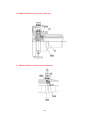
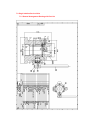
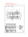
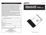
Hydraulic Retriever & Service Valve Operation & Maintenance Manual Metal Samples A Division of Alabama Specialty Products, Inc. 152 Metal Samples Rd., Munford, AL 36268 Phone: (256) 358-4202 Fax: (256) 358-4515 E-mail: [email protected] Internet: www.metalsamples.com Index CHAPTER 1 - Introduction ................................................................................................................ 1 1.1 Conformity to the Pressure Equipment Directive (PED) ......................................................... 1 CHAPTER 2 – Main Data.................................................................................................................... 2 2.1 Guarantee Restriction .............................................................................................................. 2 2.2 Tool Data - Hydraulic Retriever ................................................................................................ 3 2.2.1 Hydraulic Retrieval Tools for Single (Single Ball).e Double (Double Ball) Isolation Service Valve ............................................................................................................. 4 2.3 Restriction on use .................................................................................................................... 5 CHAPTER 3 – Technical Description ............................................................................................... 6 3.1 Double Acting Hydraulic Retriever ........................................................................................... 6 CHAPTER 4 – Operation Instruction ................................................................................................ 7 4.1 Important Safety Information .................................................................................................... 7 4.2 Operators Qualification ............................................................................................................ 8 4.3 Preparations ............................................................................................................................. 9 4.4 Retrieval from a pressurized line. .......................................................................................... 10 4.5 Installation of a Monitoring Device into a Pressurized Pipe ................................................... 17 4.6 Training program for Operators ............................................................................................. 20 CHAPTER 5 - Maintenance.............................................................................................................. 21 5.1 General .................................................................................................................................. 21 5.1.1 Introduction ................................................................................................................... 21 5.2 Maintenance instructions ....................................................................................................... 21 5.2.1 Routine Inspections before use..................................................................................... 21 5.2.2 Periodic Maintenance.................................................................................................... 23 5.2.3 Maintenance after use................................................................................................... 23 5.2.4 Storing, preservation and maintenance of preservation ..................................................... 31 CHAPTER 6 – Spare Parts List ....................................................................................................... 32 6.1 Double Acting Hydraulic Retriever ......................................................................................... 33 6.2 Service Valve ......................................................................................................................... 34 6.2.1 Single Insulation Valve .................................................................................................. 34 6.2.2 Double Insulation Valve ................................................................................................ 35 6.3 Pumps .................................................................................................................................... 36 6.3.1 Manual Hydraulic Pump ................................................................................................ 36 6.3.2 Air Hydraulic Pump ....................................................................................................... 36 CHAPTER 7 - Drawings ................................................................................................................... 37 7.1 Double Acting Hydraulic Retriever ......................................................................................... 37 7.1.1 General Arrangement Drawing with Part List ................................................................ 37 7.1.2 Detail for Seals on rear section of Retriever ................................................................. 38 7.1.3 Detail for Seals on center section of Retriever .............................................................. 38 7.1.4 Detail for Seals on front section of Retriever................................................................. 39 7.1.5 Detail for Seals on Retriever Head Valve...................................................................... 39 7.2 Single Isolation Service Valve ................................................................................................ 40 7.2.1 General Arrangement Drawing with Part List ................................................................ 40 7.3 Double Isolation Service Valve .............................................................................................. 41 7.3.1 General Arrangement Drawing with Part List ................................................................ 41 CHAPTER 8 - Sequence of Operations .......................................................................................... 42 CHAPTER 1 - Introduction 1.1 Conformity to the Pressure Equipment Directive (PED) The Tool subject of this manual, Hydraulic Retrieval Tool and Service Valve Double and Single Ball, are in compliance with "Pressure Equipment Directive (PED). Where potential hazards have been identified, appropriate warnings and safety precautions have been described throughout the manual 1 CHAPTER 2 – Main Data 2.1 Guarantee Restriction Visually inspect all components for shipping damage. If shipping damage is found, notify carrier at once. Shipping damage is not covered by the warranty. The carrier is responsible for all repair and replacement costs resulting from shipment damage. WARNING! Read and follow all instructions, warnings and cautions to avoid personal injury or property damage during system operation. METAL SAMPLES is not responsible for damage or injury resulting from unsafe use of product, lack of maintenance, incorrect installation of equipment and/or system operation. Contact METAL SAMPLES in case of doubt about any applications and safety precautions described herein. 2 2.2 Tool Data - Hydraulic Retriever The Double Acting Hydraulic can be used for replacing e.g. corrosion probes under full line pressure without shutting down and depressurizing the pipe system. The Double Acting Hydraulic Retriever is supplied with a Service Valve with single isolation (one ball) as standard. For more safety, a Service Valve with double isolation (two separate balls) is also available. NOTE! Due to the increased height of the Double Isolation Service Valve, a special Double Acting Hydraulic Retriever is required for use with this valve The Hydraulic Retriever can be operated either with a manual hydraulic pump, or an air-driven hydraulic pump. When using an air-driven pump, make sure that the pump is connected to an air supply with operational pressure between 39 - 118 psi (2.7 - 8.2 bar) and a minimum air flow of 89.8 gallons/min (340 l/min). Operative Data: Max working pressure 6090 psi (420 bar) Max/Min. working temperature 446°F (230°C) Hydraulic test pressure 9135 psi (630 bar) The Double Acting Hydraulic Retrieval Tool and Service Valve (Single & Double Ball) are PED approved. 3 2.2.1 Hydraulic Retrieval Tools for Single (Single Ball) and Double (Double Ball) Isolation Service Valve The following Double Acting Hydraulic Retrieval Tool Kits are for exclusive use with Single Isolation Service Valve: Retrieval Part Number Max Cylinder length Max retrievable probe length HA104011 HA104021 HA104031 HA104041 HA104051 HA104061 HA104071 HA104081 HA104091 HA104101 19.9 in / 505 mm 24.0 in / 610 mm 30.0 in / 760 mm 35.8 in / 910 mm 41.7 in / 1060 mm 47.6 in / 1210 mm 53.5 in / 1360 mm 59.5 in / 1510 mm 65.4 in / 1660 mm 71.3 in / 1810 mm 5.1 in / 130 mm 7.9 in / 200 mm 11.8 in / 300 mm 15.8 in / 400 mm 19.7 in / 500 mm 23.6 in / 600 mm 27.6 in / 700 mm 31.5 in / 800 mm 35.4 in / 900 mm 39.4 in / 1000 mm The following Double Acting Hydraulic Retrieval Tool Kits are for exclusive use with Double Isolation Service Valve: Retrieval Part Number HA104012 HA104022 HA104032 HA104042 HA104052 HA104062 HA104072 HA104082 HA104092 HA104102 Max Cylinder length 28.2 in / 717 mm 32.4 in / 822 mm 38.3 in / 972 mm 44.2 in / 1122 mm 50.1 in / 1272 mm 56.0 in / 1422 mm 61.9 in / 1572 mm 67.8 in / 1722 mm 73.8 in / 1872 mm 79.6 in / 2022 mm Max retrievable probe length 9.0 in / 230 mm 11.8 in / 300 mm 15.8 in / 400 mm 19.7 in / 500 mm 23.6 in / 600 mm 27.6 in / 700 mm 31.5 in / 800 mm 35.4 in / 900 mm 39.4 in / 1000 mm 43.3 in / 1100 mm NOTE! (1) If the Double Acting Hydraulic Retriever is used with standard mechanical fittings with a Hydraulic Adapter produced by Metal Samples, the max. probe / holder length is reduced by 3.15” (80mm). (2) The Retriever Kit is delivered with a Manual Pump. An Air Pump is available on request. (3) The Single Isolation Service Valves must be only used with a Double Acting Hydraulic Retrieval Tools prepared for this type of Valve, P/N HA104011 up to HA104101. (4) The Double Isolation Service Valves must be only used with a Double Acting Hydraulic Retrieval Tools prepared for this type of Valve, P/N HA104012 up to HA104102. 4 2.3 Restriction on use The maximum limits for pressure and temperature specified in section 2.2 must be observed. The owner of the pipe system where the retriever is to be used should also, in cooperation with trained retriever operators, evaluate the safety issues on the specific locations where the retrieval tool is to be used. The total process from start to finish must be evaluated, but especially the potential hazards caused by the gas/liquid flowing inside the pipelines must be considered, with special attention on the following: can the media in the pipe cause damage to the seals (standard O-ring material is Viton) in the Retriever and Service Valve? does the media in the pipe represent a hazard to the operators if they come into contact with it? If any of the above described issues, or others that might have been identified during the evaluation, are considered to represent a hazard which cannot be compensated properly for by safety precautions, then the retriever operation should not be performed under full line pressure. 5 CHAPTER 3 – Technical Description 3.1 Double Acting Hydraulic Retriever Equipment for internal corrosion monitoring can be i.e. corrosion probes, weight loss coupons and bio probes are normally installed in access fittings (of which there are many types) which have been installed on the pipe/vessel. A special version of the access fittings (T-type fittings) can also be used for installation of equipment for injection of chemicals or sampling of the contents in the pipe. The Double Acting Hydraulic Retriever is a tool which is designed for servicing all kinds of equipment that can be installed into access fittings. With the Double Acting Hydraulic Retriever, equipment can be installed into or retrieved from access fittings while the pipe system is in normal operation, i.e. under full operational pressure. The standard Double Acting Hydraulic Retriever has a pressure rating of 6090 psi (420 bar) and is PED approved. The Double Acting Hydraulic Retriever is designed to be used only on Hydraulic Access Fittings. However, it is also possible to use this tool on traditional 2" (mechanical) Access Fittings (with 3" ACME threads) if the 2" fitting has been equipped with a Hydraulic Access Fitting Adapter. The Hydraulic Access Fittings / Access Fitting Adapters do not have internal threads. Instead the retrievable parts are kept in position by use of locking pins and heavy duty covers. The Double Acting Hydraulic Retriever is designed to be lightweight and compact in size and this makes it safer and easier to operate, and can also make it possible to monitor locations which otherwise would be inaccessible due to the size of traditional mechanical retrieval tools. The main components of the retrieval tool is made in stainless steel, which makes it easy to maintain, and should ensure a long service life. The Double Acting Hydraulic Retriever is operated by either a manual hydraulic pump, or an air-driven hydraulic pump. When the Hydraulic Retriever is used on a pressurized system, the pipeline pressure alone will normally provide sufficient force for retrieval of the monitoring equipment from the access fitting and into the retriever. When monitoring equipment is to be installed, the hydraulic pump is used to create a higher pressure inside the retriever than in the pipeline, thereby pushing the monitoring equipment into the access fitting. 6 CHAPTER 4 - Operation Instruction 4.1 Important Safety Information This Manual has been prepared to provide technical information on the operation of the Metal Samples Double Acting Hydraulic Retriever, and is not intended to provide the purchaser or user with information on the proper removal of probes in a pressurized system. The procedures for probe removal in this manual are for illustrative purposes only. Specific removal procedures must be developed by the tool owner or operator for each application. As a minimum, these procedures must address the safety of the tool operator and the technical effect on the operating system. It is also necessary that the Approved Probe Removal Procedures are compared with the illustrative examples used in this Hydraulic Retriever Operation Manual to insure there are no conflicts between the examples and the Approved Probe Removal Procedures. Do only use tools made of materials that will not produce sparks when used, such as tools with plastic or brass surfaces! When operating retrieval tools, use approved personal safety tools like glasses, gloves, helmet, shoes, etc.! 7 4.2 Operators Qualification Operation of a retrieval tool on a pressurized system can be very dangerous, and must only be attempted by properly trained personnel (see section 5.6), using procedures approved by the owners of the operating system. It is very important though, that the hydraulic retriever should only be operated by people who fully understand how it works, and are trained in its use. Therefore, it is not enough just to read this manual. Operators should, before working on any "live" pipe system, be sufficiently trained by qualified instructors. Operators should also be familiar with the different components that are used with the hydraulic access fittings, e.g. Hollow and Solid Plugs, Locking Pins, Hydraulic Covers and the different types of seals used on these parts. 8 4.3 Preparations The procedure in section 4.4 describes, step by step, how to operate the Metal Samples Double Acting Hydraulic Retriever in order to perform the retrieval of a monitoring device (e.g. a corrosion probe) installed on a pressurized pipeline, and subsequent reinstallation of the monitoring device. The procedure covers use of the Double Acting Hydraulic Retriever with both the standard Service Valve and the Double Isolation Service Valve. Where there are differences in the operation of the two valve types, this is specified throughout the procedure. Before the retriever is used, it must be checked to insure that all parts are in good operating condition. See section 5.2.1, "Routine inspection before use". Before the air pump is used, please read the instruction sheet that is delivered with the pump. Before work commences on a specific location, this must be clarified with the operators responsible for the area/pipe system where the fitting is installed. Use of the Hydraulic Retriever involves bleeding of pressurized fluid/gas from the pipe system. If the pipe system contains hydrocarbons, bleeding of liquid/gas might trigger gas detectors, hence such operations must always be clarified with the operators before the job starts. The following safety precautions should apply: The operators/control room must be told when the work starts and stops at each location. The operators/control room are notified before bleeding of oil/gas, so they can bypass any gas detectors, and stop hot-work nearby, during the bleeding. 9 4.4 Retrieval from a pressurized line. 1. Make sure that there is enough space available to use the retriever. Also make sure that the size of the hydraulic retriever is sufficient for the actual probe length at the selected location. (See tables in section 2.1.1). 2. Confirm the pipeline pressure, and whether variations in pressure can be expected during the period when the hydraulic retriever is to be operated. 3. Check the hydraulic access fitting, including: 1. Check that the cover is sufficiently tightened 2. Unscrew the locking pins for inspection, one at a time 3. Check the O-rings for cuts and wear, and replace them if necessary 4. Inspect, and if necessary clean, the hole in the access fitting, especially the surface for the O-rings. (fig. 3) 4. Make sure the locking pins are sufficiently tightened after inspection 5. Remove the pipe plug, or if a continuous monitoring cable is connected, remove the cable from fitting Fig. 3 6. Remove the protective cover. Check for leaks around the plug, and around the locking pins. If leaks are discovered, then put the cover back on, and do step 3-6 once more. (fig. 4). If the leaks cannot be stopped, then put the cover back on and tighten it. Leave the access fitting until a more thorough inspection can be performed during the next shut down of the system. 7. Check external threads on access fitting. Clean and lubricate if necessary 10 Fig. 4 8. Check and inspect the O-ring on the "bottom" of Service Valve (fig. 5). Mount the service valve on the access fitting. Tighten it to the fitting with the plastic hammer 9. Fig. 5 10. Connect the hoses from the pump to the retriever. Before using the pump, observe the settings of the flow-direction valve, "RETRIEVE" and "INSTALL" (fig. 6). 11. Ensure that the valve in the retriever head (head valve) is open (1-2 turns is sufficient). For manual pumps, also check that the return valve on the pump is closed. Set the hand/airpump to "INSTALL", and pump until the connecting rod is fully extended. Continue to pump until the pressure inside the retriever is a minimum of 290 psi (20 bar) - (watch the pressure gauge on the pump). Then close the head valve, and disconnect the hoses (fig. 6). 11 Fig. 6 12. Hold the retriever so the connecting rod faces the service valve. Put the connecting rod into the service valve, and mate the threads on the rod and the plug together. Screw the rod into the plug by rotating the retriever. Screw until the rotation suddenly stops. Do not tighten (fig. 7). 13. Connect again the hoses from the pump, and set the pump to "RETRIEVE". Open the head valve, and pump 1-2 strokes on the hand/air pump. This will pull the retriever towards the end face of the service valve. 14. Connect the hammer nut to the service valve, and screw until it stops. Then tighten the hammer nut by use of the plastic hammer (fig. 7). 15. Check that the bleed-off valve on the retriever is closed. Fig. 7 12 16. Set the pump to "INSTALL", and pump until the pressure in the retriever is at least 435 - 725 psi (30 - 50 bar) higher than the pressure inside the pipeline. If it is difficult to determine the exact pipeline pressure, the pressure should be increased to an even higher level – 725 - 1450 psi (50 - 100 bar) above expected pressure in the pipeline. 17. Loosen (counter clockwise) all of the locking pins in the access fitting. The locking pins should be easy to loosen. If they are difficult to loosen (high friction), the pressure in the cylinder might be too low. The pins must then be tightened, again and the pressure increased (see step 16) before the pins are loosened again. IMPORTANT! The locking pins should only be screwed out until the head of the pin is flush with the outside of the access fitting. No threads must be visible. If the pins are unscrewed too far, they will leak when the plug is retrieved (fig. 8). Fig. 8 18. Check that the service valve is fully opened. On the double isolation service valve, both balls must be fully opened. 19. Make sure that the bleed valve on the retriever is closed For hand pump: Set the pump to "RETRIEVE". Then release the cylinder pressure by pumping one stroke on the pump For air pump: Move the handle quickly from "INSTALL" to "RETRIEVE", and avoid stopping in the center position. (Handle in center position will allow a quicker than desired retrieval of the plug/probe). If the pipeline contains gas at a pressure above 2900 psi (200 bar), the following can be done to control the pressure drop in the retriever: Close the head valve on the retriever before setting the pump to "RETRIEVE". With the handle in "RETRIEVE" position, the pressure in the retriever can be released slowly by opening the head valve. 13 Concerning the pressure in the line, to fully retrieve the plug/probe, use the hand/airpump and keep pumping until the pressure gauge on the pump shows that pressure is starting to build up inside the retriever. (Normally 25-50 strokes, depending on retriever size). This indicates that the probe is fully retrieved. Check for leaks around the locking pins. If leaks do occur, the probe must be reinstalled (see step 7-11 in the installation procedure of section 4.5). Reinstall cover, and recheck the O-rings on the locking pins IMPORTANT! When using the pump is in "RETRIEVE" position, the pressure should never exceed 1450 psi (100 bar) - (see gauge on pump). This is because if the probe for some reason should be prevented from moving out of the fitting, attempting to retrieve it at a higher pressure might cause damages to the plug or to the retriever. If the plug / probe cannot be retrieved at 1450 psi (100 bar), it should be left inside the fitting until the next shut down. 20. Close the service valve. If a double isolation valve is used, at this stage close only the lower ball (closest to the access fitting). Use of force shall normally not be required for closing the valve. If the valve cannot be closed, it is most likely due to one of the following causes: There are large amounts of sand/debris inside the valve, hampering the rotation of the ball The probe is not fully retrieved The probe is fully retrieved, but the probe length exceeds the capacity of the retriever To make sure that the probe is fully retrieved, pump some additional strokes on the pump, and check that the pressure inside the retriever increases for each stroke, and stabilizes at the higher level. (If necessary, keep pumping until such stabilization is achieved). If the valve still cannot be closed, the probe must be installed again, (see installation procedure, section 4.5, step 7-13), and the valve inspected, in order to determine the reason for this problem. 21. Assume that the service valve is closed, check that the by-pass valve on the service valve is closed. On double isolation service valves, check both by-pass valves. If the by-pass valve(s) cannot be closed, the plug/probe must be reinstalled and service valve's by-pass system checked. (See installation procedure, section 4.5, step 7-13). 22. IMPORTANT ! This section contains information about how to bleed off the pressure inside the retriever after the plug has been retrieved, and the service valve closed. Please read this section carefully. Before the retrieval operations starts, it should be agreed upon with the operators or the control room what safety precautions should apply for bleeding off the media in the retriever, (see also section 4.3, Preparations). Follow the safety precautions that have been agreed with the operators. 14 With the service valve closed, the pressure inside the retriever must be released. Use the bleed-off valve on the cylinder (fig. 9). To do this in a controllable manner, a hose can be connected to the bleed-off valve, and a can should be used to catch the gas / liquid which is bled off. (A hose for this purpose can be supplied by Metal Samples). The bleed-off valve should be left open as long as there is liquid coming out from the retriever. This to get as much liquid as possible out of the retriever before it is being disconnected from the service valve. WARNING ! When bleeding off sour gas, or other dangerous gases / fluids, a hose must Fig. 9 be used, and every precaution possible must be taken to ensure that the operators are not endangered. The procedure for bleeding off dangerous substances will be different for different situations, and therefore this manual cannot give any detailed description of such an operation. If in doubt, contact your supplier for further advice. 23. With the pressure in the retriever reduced to 0, it must be checked that the service valve is sealing properly. This can be done by closing the bleed-off valve, and leaving it closed for 1-2 minutes. Then open it again, to see if there has been any pressure build-up inside the retriever. If the service valve leaks, then check if it is properly closed. Also check that the by-pass valve is closed. If leaks in the valve cannot be stopped, the plug / probe must be reinstalled (see installation procedure, section 4.5, step 7- 12), and the valve must be serviced. For systems containing high pressure dry gas, it can be difficult to make the Service Valve to seal properly after the plug / probe has been retrieved. This is because it is difficult to reduce the pressure in the retriever quickly enough (through the bleed valve) to create the difference in pressure that is required to force the ball against its seat. To assist in creating this difference in pressure, the retriever can be utilized by pumping in "RETRIEVE" mode, as this will increase the volume inside the retriever. If the plug / probe has been fully retrieved already, the pump must be set to "INSTALL" and the plug / probe pumped towards the ball in the service Valve. Be very carefully during this pumping, to avoid having the probe coming in contact with the ball, as this might damage both the probe and the ball. Watch the pressure gauge carefully, and stop pumping immediately as soon as the pressure starts to increase. Open the bleed valve on the retriever, set the pump back to "RETRIEVE", and pump as fast as possible. This will cause the pressure drop in the retriever, and should be sufficient to make the ball seal against its seat. 15 If the gas still cannot be bled off, then close the bleed-off valve. Pump the plug back into the access fitting, tighten locking pins, remove the service valve and perform maintenance on the service valve, check the ball and sealing seats for scrape marks. 24. For double isolation valves only: When the lower ball is closed and it is sealing properly, close the upper ball. (To utilize the added safety of the double isolation valve, it is important to verify the function of the lower ball before upper ball is closed). 25. Provided the service valve is sealing properly, the retriever can now be disconnected from the valve. Loosen the hammer nut, and unscrew it from the valve. Then lift the retriever away from the service valve. If the access fitting is in 12 o'clock position, be aware of liquid that might flow out as the retriever is disconnected from the service valve. If the access fitting is in 6 o'clock position, the retriever might still be filled with liquid, and therefore, after being disconnected it must be held in the same position until it can be emptied into e.g. a bucket. IMPORTANT ! Make sure it is only the retriever that is loosened from the service valve, and that the service valve still is kept properly tightened onto the access fitting. 26. Place the retriever with the opening up, and set the pump to "INSTALL". Pump the plug / probe assembly out of the retriever. The probe and plug can now be inspected and serviced or replaced (fig. 10). Fig. 10 16 4.5 Installation of a Monitoring Device into a Pressurized Pipe The installation procedure starts where the retrieval procedure ended, i.e. with a hydraulic access fitting on a pressurized line, without a plug inside, and with a closed service valve mounted onto the fitting to contain the line pressure Before starting the installation, make sure that the retriever is clean and ready for use, ref. section 5.2.1, "Routine inspection before use". 1. Place the retriever with the opening upwards, and connect the hoses from the pump. Set the pump to "INSTALL", and pump until the connecting rod is extended. 2. Mount the plug / probe to the connecting rod. Set the pump to "RETRIEVE", and pump until the probe has been fully retracted into the retriever (fig. 11). Fig. 11 3. Lift the retriever onto the service valve, screw the hammer nut on to the valve, and tighten it. 4. Set the pump to "INSTALL". 17 5. Balance pressures on both sides of the service valve by: for standard service valves, slowly open its by-pass valve. The pressure in the retriever will now increase until it equals the line pressure. (The pressure can be read on the retriever pressure gauge). for double isolation service valves, slowly open the by-pass valve for the upper ball (closest to the retriever), and then open the upper ball itself. (Normally there will be no pressure behind this ball, but it should be opened carefully anyway, in case there is a leak past the lower ball). Now slowly open the bypass valve for the lower ball. The pressure in the retriever will now increase to line pressure. If the pressures cannot be balanced, most likely due to dirt in the by-pass valve, it will be difficult to open the service valve, especially when the line pressure is high (above 725 psi / 50 bar). The pressure should then be balanced by use of the pump To balance the pressures with the pump, use the following steps: Set the pump to "RETRIEVE", and pump until the probe is fully retrieved Install the Back Pressure Quick Coupling Assy. (NOT included in the retriever Kit) on the Bleed-off Valve. Disconnect the hose from the female quick coupling on "the middle of" the retriever, and connect it to the Back Pressure Quick Coupling Assy. on the Bleed-off Valve. Ensure that the bleed valve is open (fig. 12). Keep the pump in "RETRIEVE" position, and pump until the pressure inside the retriever equals or exceeds the line pressure. Then close the Bleed-off Valve. Move the hose from the Bleed-off Valve back to its original position. Check and make sure to have enough hydraulic oil inside the pump. Fig. 12 6. With the line pressure in the retriever, check for leaks between the retriever and the service valve. If no leaks occur, open the service valve. (For double isolation valves, open the lower ball). 7. Set the pump to "INSTALL", and pump until the plug / probe is installed into its position 18 inside the access fitting. The number of pump strokes required for this operation depends upon the line pressure and the size of the retriever. If using an air pump, the time required for this operation will be approximately 50 seconds. When the plug / probe is in position inside the hydraulic access fitting, the gauge on the pump will show that the pressure inside the retriever increases for each new pump stroke, without dropping afterwards. The retriever pressure should now be increased to 725 - 1450 psi (50 - 100 bar) above line pressure, in order to ensure that the primary packing on the plug gets properly positioned into its seat. 8. Bleed off the pressure inside the service valve by opening the retriever's or service valve's bleed-off valve carefully. Use a hose and a can to do this in a controlled manner. The same safety precautions as for retrieval operations shall apply, see section 4.4 step 22 for further advice. 9. Tighten all locking pins on the access fitting. The pins must be tightened evenly around the access fitting, in order to avoid the plug being pushed against one side of the fitting. Therefore, screw in all pins until they touch the plug. Then tighten one by one (fig. 13) approx. 1/4 of a turn, and repeat until all locking pins are sufficiently tightened. Expect a total of 3-4 turns for adequate tightening. If the locking pins suddenly stop after only 1-3 turns, or if they can easily be screwed all the way in (4-5 turns) without any resistance, this indicates that the plug is not quite in position. Loosen all pins, retrieve the plug / probe assembly again, and look for damages that might prevent proper installation (see section 4.4, step 17-25). Fig. 13 10. When the plug is fixed in position by the locking pins, the pressure in the retriever can released. Set the pump to "RETRIEVE" and pump 1-2 strokes. The gauge on the pump shall now show 0. 11. Close the bleed-off valve and wait for 1-2 minutes. Then open it again and see if pressure has built up inside the retriever. A pressure build-up indicates that the plug is not sealing properly in the access fitting. If this happens, use the pump to increase the retriever pressure to a level at least 1450 psi (100 bar) above pipeline pressure. Then loosen the locking pins, and re-tighten them. Check again if the leaks are still there. If so, the plug must be pulled out for inspection / replacement of the primary packing. (See instruction for retrieval, section 4.4 step 17-25). 19 12. Providing no leaks occur, the retriever can be removed. Loosen the hammer nut, and unscrew it completely from the service valve. (Be aware of fluid that might flow out when the retriever is being disconnected). Set the pump to "INSTALL", and pump until the connecting rod is fully extended. Continue to pump until the gauge on the pump shows that the pressure inside the retriever is at least 290 psi (20 bar). Then close the retriever head valve, and release the pressure in the pump / hose. Disconnect the hoses from the retriever, and then unscrew the retriever connecting rod from the plug by rotating the retriever. 13. Use the hammer to loosen the service valve from the hydraulic access fitting. Remove the valve. 14. Clean the end of the plug, and especially the hole where the connecting rod was mounted. Remove all dirt and moisture carefully. NOTE! If a probe with an electrical connector has been installed, the probe connector must be cleaned thoroughly with a cleansing agent suitable for electrical equipment. 15. Check external threads on the hydraulic access fitting. Lubricate them properly (fig. 14). 16. Put on the heavy duty protective cover. Tighten with a 4.134” (105 mm) spanner, or a suitable pipe wrench. This will take the load off the locking pins (fig. 14). 17. Reinstall the pipe plug (or continuous monitoring cable if applicable) (fig. 14). ) Fig. 14 4.6 Training program for Operators Only specially trained personnel should attempt to operate the Double Acting Hydraulic Retriever. 20 CHAPTER 5 – Maintenance 5.1 General 5.1.1 Introduction A Proper and regular maintenance is very important in order to ensure trouble free operation of the Double Acting Hydraulic Retrieval Tool, and to keep it in good operating condition over a long period of time. 5.2 Maintenance instructions 5.2.1 Routine Inspections before use After a storage period, the retriever must be checked to ensure that it is in operational condition before being used. The check points described in this section assume the retriever has been properly cleaned and maintained after its last use. If in doubt, follow the maintenance instructions in section 5.2.3 instead. If the retriever is to be used over a period of several days, this check should also be performed daily, before the first retrieval operation. 5.2.1.1 Double Acting Hydraulic Retriever Check that all parts are present, and that they are clean and undamaged. Check the internal seals as follows: Connect both hoses from the pump to the retriever. Set the pump to "INSTALL", and start pumping. The rod shall extend with a smooth and even movement. Continue to pump until the rod is fully extended, and the pressure gauge on the pump shows 1450 psi (100 bar). Leave the pressure on for 1-2 minutes, to see that it stabilizes and does not drop significantly. Set the pump to "RETRIEVE", and pump until the connecting rod is fully retracted. The rod should retract with a smooth and even movement. Continue to pump until the pressure gauge on the pump shows 1450 psi (100 bar). Leave the pressure on for 1-2 minutes, to see that it stabilizes and does not drop significantly. If the pressure drops more than 290 - 435 psi (20 - 30 bar) in any of the above described steps, the internal seals must be checked and replaced if necessary. Follow the instructions in section 5.2.3. 21 Check that the O-ring on the union thread adaptor (for sealing against the service valve) is present and undamaged. 22 5.2.1.2 Service Valve Check that all parts are present, especially the bolts connecting the valve sections together. Check that the service valve is clean and undamaged both externally and internally. Check that the service valve can be opened and closed easily. Check that there are no deep scratches or other damages in the surface of the Ball(s). (Minor scratches will usually not cause any problems). Check that the O-ring in the bottom end (for sealing against the access fitting) is present and undamaged. 5.2.2 Periodic Maintenance There is no regular periodic maintenance - based on time of use or number of operations - of this equipment. The need for periodic maintenance will depend on the conditions under which the equipment is being used. If the retriever is used on pipe systems containing large amounts of sand or other debris, it may be necessary to go through the maintenance routine quite frequently to keep the retriever sufficiently clean during operations. In severe cases with e.g. lots of sand in the pipe system, it might be required to clean the retriever after each single retrieval operation. This is in order to avoid high wear, and / or other damages to the internals of the retriever. To perform periodic cleaning, follow the instructions in section 5.2.3.1 Disassembly and cleaning. 5.2.3 Maintenance After Use When a series of retrieval operations are completed, and the hydraulic retriever is to be stored for a while, it should be disassembled, cleaned and checked following the procedure below. 5.2.3.1 Double Acting Hydraulic Retriever Before starting, make sure to have cleaning rugs, a can, and a stick of wood (or another non-metallic material) of approx. the same length as the retrieval tool available. Disassembly and cleaning 1. Connect the hoses from the pump. Set the pump to "RETRIEVE", and pump until the inner barrel (3) and connecting rod (4) is fully retracted into the retriever 2. Loosen the six bolts on the main cylinder head (10), and remove the main cylinder head (2) and the protection ring (8). 3. Hold the retriever over the can and pump slowly (in "RETRIEVE" mode) until the seals on the rear end of the inner barrel come out of the main cylinder (1). Put the wooden stick into the opposite end of the main cylinder and push the inner barrel slowly and carefully out of the main cylinder. Be aware that as soon as the inner barrel comes loose from the main cylinder, all the oil that is inside the retriever will flow out, so make sure to keep the opening of the main cylinder over the can. Also note that the 23 inner barrel is filled with hydraulic oil, which will flow out of the four holes in the barrel. 4. Unscrew the washer (5) from the end of the connecting rod, and push the rod out of the inner barrel. The retriever is now sufficiently disassembled for cleaning and inspection. The following steps (6 and 7) should only be performed if the union thread adapter (6), pressure gauge (39), bleed valve (38) or cylinder head valve (11-20) are defect, or leaks have occurred in connection with these parts. 5. Loosen the set screw M5x5 (24) on the union thread adapter (6). Unscrew the union thread adapter from the main cylinder (use a special hook wrench), and remove the hammer nut (10). 6. Unscrew the pressure gauge (39), the bleed valve (38) from the cylinder. 7. Unscrew the cylinder head valve assembly (11-20) by unscrewing the valve housing (11). Loosen the set screw M5x12 (15) and remove the handle (14) from the valve stem (13). Unscrew the gland (12) from the valve housing. Unscrew the valve stem (13) from the valve housing. Remove seals (17, 20) and compression ring from the valve housing. If damage to any of the remaining parts (quick couplings and handle) has occurred, these parts must also be removed, checked, and replaced as necessary. 8. Remove all O-rings, back up rings and wear rings, but leave the wiper ring (33) on the inner barrel in place. These rings are very easily damaged when they are removed, and should therefore only be removed when they are worn out and need to be replaced. 9. Clean all parts thoroughly with a suitable detergent, especially the internals of the main cylinder, the O-rings and wear rings, and their grooves on the inner barrel and connecting rod. 10. Check the seals and wear rings carefully. If any of the seals have scratches, or show other signs of wear, they must be replaced. If any of the wiper rings on the inner barrel need to be replaced, see instructions for "Replacement of wiper rings" in the following section. 11. Check all parts for damage, especially the internal surfaces of the main cylinder and the inner barrel. If all parts, including seals, are found to be in good condition, the retriever can be assembled again. The assembly shall take place in the reverse order of the described disassembly procedure. Be absolutely certain that all threaded surfaces are cleaned from particles (sand, metal particles etc.) and properly lubricated before any of the parts are mounted together. This is especially important when mounting the union thread adapter to the main cylinder. Use a high quality anti-seize lubricant, e.g. "Copaslip", "Molyslip" or similar types. After all seals have been installed on the correct locations, use O-ring grease to lubricate the seals, especially before the connecting rod is installed into the inner barrel, before the inner barrel is installed into the main cylinder, and before the union thread adapter is installed on the main cylinder. Be careful when putting the parts back together. Special care should be taken to ensure that the seals are not damaged when the components are assembled. 24 If the quick couplings (40, 41) are removed from the main cylinder for maintenance or replacement, make sure that they are reinstalled in correct positions. The female one shall be installed on the retriever head, while the male one shall be installed on the "middle" of the retriever main cylinder. IMPORTANT! If the bolts for the retriever head are to be replaced, always replace them with new original bolts from Metal Samples. If other types of bolts are used, the Double Acting Hydraulic Retriever will no longer be PED approved. The tightening torque for the M16 bolts on the retriever head is 113 ft-lbs (153 Nm). 25 Replacement of wiper rings The hydraulic retriever has one wiper ring installed on the inner barrel. When this wiper rings is damaged and need to be replaced, the following instructions should be followed. Please note that new wiper ring will be a lot easier to install and form to shape if it are heated first. Heating shall be done by keeping the wiper ring in boiling water for a few minutes. Do NOT attempt to heat the wipers in any other way. Internal wiper, (see figure 15 e drawing in section 7.1.3). 1. Make sure a new wiper of correct type is available. The Internal wiper (33) is installed together with an O-ring (34) in a common groove. 2. Remove the old wiper from the groove by use of i.e. a small screwdriver. 3. Remove the O-ring which is installed in the same groove under the wiper 4. Clean the groove properly 5. Install a new O-ring into the groove, and place it in the groove as shown on the drawing. 6. Form the wiper into a kidney shape without creating any sharp bends, fig. 15. 7. Place the "deformed" wiper in the groove over the O-ring , and make sure the orientation is correct, with the pointed (cleaning) side of the wiper facing out of the inner barrel as per fig. 15. 8. With the wiper placed in the groove, reform it back to its original shape, first by use of a finger or a small round object. When the wiper is roughly formed to shape in the groove, final shape calibration shall be done i.e. by use of the Glydring Calibrator. This calibrator has a shaft section with diameter 1.1” (28 mm). Slide the tapered end of the shaft carefully into the wiper, and push the calibrator into the inner barrel until it stops. Keep it in this position for 2-3 minutes. The internal wiper is now ready for use. 26 Fig. 15 Preservation If the retrieval tool is to be stored after maintenance, it should be preserved with a Multi-Purpose Lubricant. Make sure to select a type that also will drive out moisture and protect against corrosion. 27 5.2.3.2 Single Isolation Service Valve Maintenance of the Service Valve is basically determined by the environment in the process pipe. Presence of sand or other deposits will require frequent cleaning of the valve, maybe as often as after each retrieval / installation operation, while when used with "clean" liquids, a daily cleaning might be sufficient. After each use, check if the valve can easily be opened / closed. If the rotation of the ball is obstructed by dirt, it must be cleaned. For "quick" cleaning, compressed air can be blown inside the valve (around the ball) to remove all deposits. Then lubricate the ball with oil, and check that it rotates properly before next use. If this is not successful, the valve must be disassembled and serviced as described below. Before storage of the service valve, it should be disassembled and cleaned properly, as described in the following instructions. Disassembly and cleaning (See also drawings and parts list in section 7.2 and 7.3. Numbers in ( ) indicate pos. nos. in parts list). 1. Remove the handle (21-24). 2. Loosen the six bolts M12x40 (15), and remove the end section (14). 3. Rotate the stem (5) to "closed" position, and then remove the ball (4). 4. Remove the Seeger (16). 5. Remove the stop ring (6). 6. Push the stem (5) into the main body (1). 7. If the main seal (11) needs replacement, then unscrew the seal carrier (12). 8. Unscrew and remove the by-pass stem (17). 9. Check and eventually replace the by-pass stem O-ring (19). IMPORTANT! If the bolts for the Service Valve Body are to be replaced, always replace them with new original bolts from Metal Samples. If other types of bolts are used, the Service Valve will no longer be PED approved. The tightening torque for the M12 bolts is 113 ft-lbs (153 Nm). Preservation If the Service Valve is to be stored after maintenance, it should be preserved with a Multi-Purpose Lubricant. Make sure to select a type that also will drive out moisture and protect against corrosion. 28 5.2.3.3 Double Isolation Service Valve Maintenance of the Service Valve is basically determined by the environment in the process pipe. Presence of sand or other deposits will require frequent cleaning of the valve, maybe as often as after each retrieval / installation operation, while when used with "clean" liquids, a daily cleaning might be sufficient. After each use, check if the valve can easily be opened / closed. If the rotation of the ball is obstructed by dirt, it must be cleaned. For "quick" cleaning, compressed air can be blown inside the valve (around the ball) to remove all deposits. Then lubricate the ball with oil, and check that it rotates properly before next use. If this is not successful, the valve must be disassembled and serviced as described below. Before storage of the service valve, it should be disassembled and cleaned properly, as described in the following instructions. Disassembly and cleaning (See also drawings and parts list in section 7.2 and 7.3. Numbers in ( ) indicate pos. nos. in parts list). 1. Remove the handle (21-24). 2. Loosen the six bolts M12x120 (15), and remove the end section (14). 3. Rotate the stem (5) of the upper body (25)to "closed" position, and then remove the ball. 4. Remove the Seeger (16) 5. Remove the stop ring (6) 6. Push the stem (5) into the upper body (25) 7. Repeat steps 3 -6 for main body (1) 8. If the main seals (11) needs replacement, then unscrew the seal carriers (12) 9. Unscrew and remove the by-pass stem (17) 10. Check and eventually replace the by-pass stem O-ring (19). IMPORTANT! If the bolts for the Service Valve Body are to be replaced, always replace them with new original bolts from Metal Samples. If other types of bolts are used, the Service Valve will no longer be PED approved. The tightening torque for the M12 bolts is 113 ft-lbs (153 Nm). Preservation If the Double Service Valve is to be stored after maintenance, it should be preserved with a Multi-Purpose Lubricant. Make sure to select a type that also will drive out moisture and protect against corrosion. 29 5.2.3.4 Manual (hand operated) Hydraulic Pump The hydraulic pump usually does not need any special maintenance. However, when the pump is to be stored for a while after a series of operations, the following instructions should be followed: Visual inspection. Do a visual inspection of the pump and hoses, and make sure that all parts are in good working condition. Pay special attention to the following items: Hoses. There shall be no visual damages to the outer sheet of the hoses. Quick connects. These shall connect and disconnect easily, and there shall be no damages externally or internally. Pressure gauge. The gauge shall be undamaged and react immediately to increased pressure. Change oil in the reservoir. The hydraulic fluid should be replaced due to the possibility that it has been contaminated with moisture or other liquids / gases from the pipeline that subsequently could cause corrosion attacks inside the pump. Do as follows: Empty the tank completely. Fill up with new hydraulic fluid. Connect the hoses to the pump. Unscrew the quick connects from the free ends of the hoses. Pump 10-20 strokes in both "retrieve" and "install" mode, and make sure that new hydraulic fluid is flowing out through both hoses. Put the quick connects back on the hoses If any further maintenance or repair should be required (replacement of seals etc.), instructions for this is described in the "Repair Parts Sheet" which is delivered with the pump. For any further maintenance or spare parts please refer to the pump manufacturer directly. 5.2.3.5 Air operated Hydraulic Pump Basic operation and maintenance of the air operated pump is described the "Instruction Sheet" which is included in the retriever kit If any further maintenance or repair should be required (replacement of seals etc.), instructions for this is described in the "Repair Parts Sheet" which is delivered with the pump. For any further maintenance or spare parts please refers to the pump manufacturer directly. 30 5.2.4 Storing, preservation and maintenance of preservation 5.2.4.1 Preservation and storage Preservation As described in section 5.2.3, if the retrieval tool and/or service valve is to be stored for a while after maintenance, the equipment should be preserved with a Multi-Purpose Lubricant. Make sure to select a type that also will drive out moisture and protect against corrosion. Storage After the equipment has been properly cleaned, maintained and preserved (ref. section 5.2.3), it should be stored in the original transport cases in which it was delivered. The cases should be dry and clean on the inside before the equipment is being placed into them. The equipment shall be stored indoors in a dry area. 5.2.4.2 Maintenance during storage If the equipment has been preserved for storage as described in section 5.2.3, no additional maintenance during storage is required. 31 CHAPTER 6 - Spare Parts List All components which under normal operating conditions may require replacement due to destruction, wear, etc., are noted in a separate spare parts list for the following type of equipment: Double Acting Hydraulic Retriever Single Isolation Service Valve Double Isolation Service Valve Manual (hand operated) Hydraulic Pump Air-driven Hydraulic Pump The spare parts lists include: description, with material specification (if applicable) Metal Samples Part No. Metal Samples will normally have all recommended spare parts in stock. 32 6.1 Double Acting Hydraulic Retriever Under normal operating conditions, the following spare parts are sufficient to keep the Double Acting Retriever in good operating condition: Item 1 2 Part No. Spare part Seal Kit for Double Acting Hydraulic Retriever Repair Kit for Double Acting Hydraulic Retriever KR1015 C/F * Material Viton / PTFE Viton / PTFE Item 1, Seal Kit, includes all elastomer seals (O-rings, sliding rings, special seals etc.) that are used in the Double Acting Hydraulic Retriever as per list below with P/N: COMPRESSION RING SEAL RING O-RING 14,0x1,78 O-RING 8,73x1,78 O-RING 4,48x1,78 O-RING 58,42x2,62 O-RING 67,95x2,62 O-RING 47,22x3,53 BACK-UP RING, SPIRAL 225 SLYDRING Ø55 O-RING 40,87x3,53 BACK-UP RING SPIRAL 223 SLYDRING Ø48 O-RING 28,24x2,62 BACK-UP RING ID28 WIPER, ROD Ø28, TURCON EXCLUDER O-RING 29,82x2,62 O-RING 32,99x2,62 BACK-UP RING, OD38 SLYDRING Ø38 Item 2, Repair Kit, add to the Seal Kit the components that usually will require replacement after the retrieval tool has been used for a while, such as Quick Couplings and Retriever Head Bolts as follows: COMPRESSION RING BLEED VALVE, 10.000 PSI QUICK COUPLING, FEMALE, JN 115 QUICK COUPLING, MALE, JN 115 PRESSURE GAUGE 0-600 *C/F – Call Factory. 33 6.2 Service Valve 6.2.1 Single Insulation Valve Under normal operating conditions, the following spare parts are sufficient to keep the Single Isolation Service Valve in good operating condition: Item 1 2 3 Spare part Seal Kit for Single Isolation Service Repair Kit for Single Isolation Service Ball for Service Valve Part C/F* C/F* C/F* Material Viton / PTFE 17-4 PH Item 1, Seal Kit, includes all elastomer seals (O-rings, sliding rings, special seals etc.) that are used in the Single Insulation Valve as per list below with P/N: O-RING 59,5x3,00 O-RING 18,64x3,53 O-RING 79,5x3,00 O-RING 84,5x3,00 O-RING 55,25x2,62 O-RING 4,48x1,78 BALL SEAT MAIN SEAL Item 2, Repair Kit, add to the Seal Kit the components that usually will require replacement after the retrieval tool has been used for a while, such as ball valve, needle valve etc., as follows: 2" BALL VALVE NEEDLE VALVE SERIE 6000 SEAL CARRIER BY-PASS STEM PIN 5X50 Item 3, Ball, might need replacement if the Service Valve is used on systems with large amounts of sand or other particles that might cause scratches or other damages to the surface of the Ball. Such damages might cause minor leaks when the Valve is used on gas systems. Please note that the Ball is also included in the Repair Kit *C/F – Call Factory. 34 6.2.2 Double Insulation Valve Under normal operating conditions, the following spare parts are sufficient to keep the Double Isolation Service Valve in good operating condition: Item 1 2 3 Spare part Seal Kit for Double Isolation Service Repair Kit for Double Isolation Service Ball for Service Valve (Not2: 2 pieces for each double valve) Part Material KR1014 Viton / PTFE C/F* C/F* 17-4 PH Item 1, Seal Kit, includes all elastomer seals (O-rings, sliding rings, special seals etc.) that are used in the Single Insulation Valve as per list below with P/N: O-RING 59,5x3,00 O-RING 18,64x3,53 O-RING 79,5x3,00 O-RING 84,5x3,00 O-RING 55,25x2,62 O-RING 4,48x1,78 BALL SEAT MAIN SEAL to note that the quantity are two for each item except for O-ring 59,5x3,00 that remain one. Item 2, Repair Kit, add to the Seal Kit the components that usually will require replacement after the retrieval tool has been used for a while, such as ball valve, needle valve etc., as follows: 2" BALL VALVE NEEDLE VALVE SERIE 6000 SEAL CARRIER BY-PASS STEM PIN 5X50 to note that the quantity are two for each item Item 3, Balls, might need replacement if the Double Service Valve is used on systems with large amounts of sand or other particles that might cause scratches or other damages to the surface of the Balls. Such damages might cause minor leaks when the Valve is used on gas systems. Please note that the Balls are also included in the Repair Kit. C/F* - Call Factory. 35 6.3 Pumps 6.3.1 Manual Hydraulic Pump Under normal operating conditions, the following spare parts are sufficient to keep the Manual Hydraulic Pump in good operating condition: Item 1 2 3 Spare part Repair Kit for Manual Hydraulic Pump Hydraulic Hose with Quick coupling installation side Hydraulic Hose with Quick coupling retrieve side Part No. Material SEE PUMP MANUFACTURER C/F* C/F* - Item 1, Repair Kit, includes all seals and other components that usually will require replacement when the pump is to be overhauled. Ask directly to pump manufacturer. Item 2 and 3, Hydraulic Hoses with Quick Couplings, shall always be replaced if there are visible damages in the outer sheet of the hose. The Quick Couplings are different on the two hoses (to avoid the hoses from being incorrectly connected), so please make sure to order the correct hose. 6.3.2 Air Hydraulic Pump Under normal operating conditions, the following spare parts are sufficient to keep the Manual Hydraulic Pump in good operating condition: Item 1 2 3 Spare part Part No. Material Repair Kit for Air-driven Hydraulic Pump SEE PUMP MANUFACTURER Hydraulic Hose with Quick coupling C/F* installation side C/F* Hydraulic Hose with Quick coupling retrieve side Item 1, Repair Kit, includes all seals and other components that usually will require replacement when the pump is to be overhauled. Ask directly to pump manufacturer. Item 2 and 3, Hydraulic Hoses with Quick Couplings, shall always be replaced if there are visible damages in the outer sheet of the hose. The Quick Couplings are different on the two hoses (to avoid the hoses from being incorrectly connected), so please make sure to order the correct hose. * C/F – Call Factory. 36 CHAPTER 7 - Drawings 7.1 Double Acting Hydraulic Retriever 7.1.1 General Arrangement Drawing with Part List 37 7.1.2 Detail for Seals on rear section of Retriever 7.1.3 Detail for Seals on center section of Retriever 38 7.1.4 Detail for Seals on front section of Retriever 7.1.5 Detail for Seals on Retriever Head Valve 39 7.2 Single Isolation Service Valve 7.2.1 General Arrangement Drawing with Part List 40 7.3 Double Isolation Service Valve 7.3.1 General Arrangement Drawing with Part List 41 CHAPTER 8 - Sequence of Operations DOUBLE ACTING HYDRAULIC RETRIEVER TOOL PRELIMINARY PRECAUTIONS Check if maintenance of retrieval tool, service valve and pump has been properly carried out. Make a trial in the workshop to ensure that all parts are in good working conditions. Check the threads by screwing the service valve onto the retrieval tool & onto the access fitting. Check the oil level in the pump. The quantity of hydraulic oil in the pump and in the retrieval tool must not exceed the quantity required and indicated in the manual of the pump. Check that the line pressure is compatible with the one indicated in this manual. Check the dimension of the probe to retrieve to ensure that the retriever model is suitable for operations. RETRIEVAL OPERATIONS 1. Remove the cover slowly. If any leaks occur, retighten the cover well then check if the locking pins and o-rings are clean and well tighten then repeat operation. If leaks insist then retighten the cover and advise the control room for check during shut down. 2. Connect hoses from pump to retriever. 3. Open the retriever head valve. 4. Set pump to install and pump until connecting rod is fully extended and pressure reaches approx. 725 psi (50 bar) - (see pressure gauge on the pump). 5. Close retriever head valve and disconnect the hoses from retriever. 6. Make sure that the o-ring at bottom of service valve is in good conditions. 7. Screw the service valve on the access fitting and ensure that the service valve is in proper position and the by-pass is closed. 8. Place the retriever on the service valve. 9. Screw the rod into the plug by rotating the retriever. 10. Connect hoses and open the head valve. 11. Set pump to retrieve and pump slowly in order to be able to screw and tighten the hummer nut. Onto the service valve. 12. Check that the bleed valve of retriever is closed. 13. Set the pump to install and pump to approx. 725 psi (50 bar) over the line pressure (ask control room about the line pressure). 14. Release the locking pin (according to the sequence showed in this manual) until they are flush with access fitting. 15. Set pump to retriever and pump until pressure is built up inside the retriever (max 1450 psi / 100 bars). If line pressure (at least 87 psi / 6 bar) is sufficient to retrieve without pumping, set the pump to neutral, open the retriever head valve slowly and wait until the pressure in the pump is 0. At this point the pressure gauge of the retriever must indicate the same line pressure. 16. Close the service valve. 17. Release the pressure with the retriever/valve bleed valve. 18. Unscrew the retriever from service valve loosing the hummer nut. 19. Place the retriever with opening up and set the pump to install. 20. Pump until the probe/plug are out. 21. Unscrew probe/plug from rod. 22. Change corrosion probe/coupon and carry out maintenance (change primary packing and, if needed, wear rings). 42 INSTALLATION OPERATION 1. Connect the retriever to the pump. 2. Set the pump to install and pump until the rod is extended. 3. Mount the plug/probe to the rod. 4. Set pump to retrieve and pump until the probe is retracted into the retriever. 5. Screw the retriever to the service valve and tighten the hummer nut. 6. Open valve by pass to balance the pressure. 7. Open the service valve and then close the by-pass. 8. Set pump to install and start pumping until the plug seals to the access fitting. As soon as this happens the pressure gauge of the pump will immediately jump to higher pressure than the line pressure, continue pumping to approx. 725 psi (50 bar) over the line pressure. 9. Open the bleed valve of retriever and/or service valve to release the pressure inside the cylinder. Make sure that the gauge of the retriever shows 0. 10. Tighten the 4 locking pins. 11. Loosen the hummer nut and unscrew it from service valve. 12. Set pump to install and pump until the connecting rod is fully extended. 13. Close the retriever head valve and disconnect hoses from retriever. 14. Unscrew the rod from the plug by rotating the retriever. 15. Remove the service valve from the fitting. 16. Screw the protective cover and tighten well (grease the access fitting threads). 43