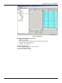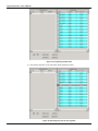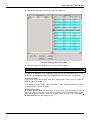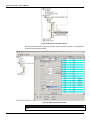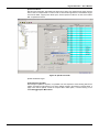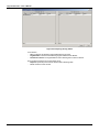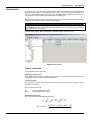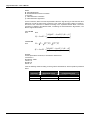
1
JUN / 05
Version 8
T L S T D F 6 5 ME
www.smar.com
Specifications and information are subject to change without notice.
Up-to-date address information is available on our website.
web: www.smar.com/contactus.asp
Table of Contents
TABLE OF CONTENTS
Tag List Generator ............................................................................................ 1
TAG LIST GENERATOR and DF65 OPC Server Installation ........................................... 1
Required System .......................................................................................................................................................... 1
Preparing the Installation ............................................................................................................................................ 1
Introduction ........................................................................................................................ 1
Using the Tag List Generator ............................................................................................ 2
Creating a New Project ................................................................................................................................................ 2
Adding and Removing ports ....................................................................................................................................... 2
Port Settings ................................................................................................................................................................. 3
Specific Configuration for the serial physical mean ................................................................................................. 3
Specific configurations for communication via Ethernet ......................................................................................... 4
Adding a New Port ....................................................................................................................................................... 4
Editing/ Removing Ports.............................................................................................................................................. 4
Redundancy........................................................................................................................ 5
Application Example .................................................................................................................................................... 5
The main path ............................................................................................................................................................... 5
The redundant path...................................................................................................................................................... 6
Adding or Removing a Configuration............................................................................... 6
Adding a Configuration ............................................................................................................................................... 7
Editing/Removing a Configuration / Device ..................................................................... 9
Saving the Project .............................................................................................................. 9
The OPC Menu.................................................................................................................... 9
Registering the Project ................................................................................................................................................ 9
Generating the Tag List Table ................................................................................................................................... 10
Verifying the Active Tag List table............................................................................................................................ 11
Viewing the Tag List Table .............................................................................................. 11
Tag List ....................................................................................................................................................................... 11
MCT ............................................................................................................................................................................. 11
Conversions...................................................................................................................... 19
Type of conversion .................................................................................................................................................... 19
Status provided by the DF65 OPC Server ...................................................................... 22
Block View Status ...................................................................................................................................................... 23
The OPC Monitor Software .............................................................................................. 24
III
Tag List Generator – User’s Manual
IV
Tag List Generator
TAG LIST GENERATOR
TAG LIST GENERATOR and DF65 OPC Server Installation
Required System
- Operating System Æ Windows NT 4.0 – Service Pack 6, Windows 2000 (Service Pack 2), or
Windows XP.
- Computer Æ PC –Pentium Processor 400 MHz or higher.
- RAM Æ 64 Mbytes (128Mbytes for Windows XP)
- Disk Space Æ 10 Mbytes of HD.
Preparing the Installation
Using the Smar installation CD “SYSTEM302 Information”, click on the OPC Server V8 and Tag List
Generator V8 to install the DF65 OPC Server and Tag List generator respectively.
Introduction
The software Tag List Generator for the DF65 OPC Server is developed to generate an information
Table to the DF65 OPC Server telling which the Tags are for each Modbus Address.
In the HMI side, just configure using links to Tags, in this way, if the user changes the DF65
configuration (the Modbus address will change), but the Tags will not. The OPC Server will be able
to read the new Tag List generated after the changes made with the LogicView.
Tag List enables the USER to enter scaled values for Tag values in engineering units. The Tag
Scaling allows the user to convert a raw value (unscaled value from the Device) to a given numeric
range (in engineering units).
Using the TreeView the USER can select, add, create, delete, and edit the List of Communications
Connections (Ports), List of Devices, Types of Conversions.
Under the Controller (Device) Level, a list of Tags will be shown, and the Properties for this Tag will
be visualized on the right Frame of the Main Application Frame.
For each Tag, the user can select if this Tag Value will have Conversion or Not and the Type of
Conversion that will apply for this Tag Value.
The versions 8.54 and later of the Tag List and support the configuration of the MCT for the DF65.
MODBUS Cross Table (MCT) is a technique to optimize variable MODBUS addresses that can
significantly increase the speed of MODBUS drivers when accessing variables in a Smar DF65
system.
Note: This function is only available for DF65 systems with DF65E or DF65ER.
1
Tag List Generator – User’s Manual
Using the Tag List Generator
Creating a New Project
To create a New Project, click on the File menu, then click New, or click on New button, on the
toolbar.’
Figure 1- Creating a new project
To open an existing project, to save a project or to close the current project just click on the File
menu then click on Open , Save or Close respectively, or click on the icons Open, Save or Close
(Windows standard) on the toolbar.
Adding and Removing ports
The DF65 OPC Server supports all types of port combinations (COM1, COM2, Ethernet) having
serial and Ethernet communication on the same configuration.
Once the user starts a new project, the Tag List will open a window similar to Figure 2. Next, by right
clicking the Communication item, Tag List will display a window where the user can configure the
parameters described below.
Figure 2- Adding a new port
Note
The user must certify that the chosen configuration option (Baud Rate or IP address) is the same
as the DF65 configuration, which will be monitored.
2
Tag List Generator – User’s Manual
Figure 3- Communication Parameters
Port Settings
Port Name (Connection)
The user must create a Tag for the port to be configured on the Tag List. This tag will be used to
define the first Browser level on the Tag List OPC Server.
Scan Period
It is the time it takes for the DF65 OPC Server to read the Tags (OPC Points) from every slave
devices, that is, the time between cyclic questions.
Retry Period
When the OPC Server Client runs out of configured tries in Retries, it verifies each time interval
established by Retry Period whether or not the connection is active.
Timeout
Waiting time for a response after a message from the DF65 Server is being sent to the slave. After
this period of time, the DF65 OPC Server retries to establish communication, based on the number
configured on Retries.
Retries
Number of times the DF65 OPC Server software will try a new communication after waiting for the
specified value on the Timeout parameter.
Specific Configuration for the serial physical mean
If the user chooses to use serial communication, it can be through EIA-232 or EIA-485. The
connection and cable specification are the same used in the communication between the DF65 and
the LogicView, and are described in the “DF65 Manual”.
Com
Allows the user to choose which serial port will be used for communication.
CTS Output Control
When this parameter is enabled, the OPC Server will transmit only when the CTS is active.
3
Tag List Generator – User’s Manual
RTS Control
The options of this parameter are:
Disable: RTS inactive (off)
Enable: RTS active (on)
Handshake: Activates the RTS, if the receiver buffer is ¾ occupied and disables when the receiver
buffer is less than half occupied.
Toggle: RTS will be activated if there are bytes to be transmitted, and RTS will be disables after
every byte is transmitted.
Specific configurations for communication via Ethernet
IP Address
In case of Ethernet TCP/IP communication, the user should set the logic controller Ethernet card’s
IP address (MB700 or ENET700) which should be communicated.
Figure 4- Adding an Ethernet Port
Adding a New Port
The user can add more serial ports or Ethernet if required. To add a new port, right-click at
Communication Connections and select Add.
Figure 5- Adding a New Port
Editing/ Removing Ports
The user can edit or erase a communication Port, for that, just right click on the added port and the
user can change its current settings, or click on Remove to remove the desired port.
4
Tag List Generator – User’s Manual
Redundancy
The DF65 OPC Server supports system redundancy. The OPC redundancy follows a main path
philosophy and a redundant path (backup). When the system detects the main path is not
communicating, the redundant path takes over communication. When communication on the main
path returns, again, it becomes the active path and the redundant gets back to being the backup.
The redundant path, even in a state of backup, it tests itself if everything is OK. Each port (main or
backup) notifies its current status through Status.
Redundancy could take place even in different physical means/data link layer: MODBUS TCP and
MODBUS RTU. For example, two Ethernet networks or even one Ethernet network and one EIA
485 network. The user can configure an existing redundant network on the system.
Application Example
Consider an application example shown in Figure A where the DF65 OPC Server monitors points
from 3 DF65 in an Ethernet network. In this case it is used path redundancy for the DF65’s, which in
case of main path failure; the DF65 OPC Server uses an alternative path for supervision.
Figure 6- An application involving an DF65 OPC Server, DF65 and MB700.
The main path
Right after a new project is created, the Tag List Generator will ask how the DF65 OPC Server and
the DF65 will communicate. The DF65 supports the communication via serial port (232 or 485) or
via Ethernet (TCP/IP). In the case of the next figure, the main path is through the Ethernet port
(”Main_Port”)
5
Tag List Generator – User’s Manual
Figure 7- Choosing a communication channel
The redundant path
After configuring the main path, the user should add a new port (channel) which will be the
redundant (backup).
Figure 8- Adding a redundant port
Adding or Removing a Configuration
Before adding a new configuration, the user is supposed to create a configuration in the LogicView
software.
Note
If the user has several DF65’s with different addresses, a configuration file should be generated
(*.PL7, *.PL8) with a different name for each DF65 used in the project.
6
Tag List Generator – User’s Manual
Adding a Configuration
The configuration must be a valid configuration generated by LogicView from Smar.
To add a new configuration the user should open the menu Edit Æ Add or in the left pane of the
Tag List Application.
Figure 9- Adding a new configuration
After the user adds a configuration, the Tag List will open a window (Figure 10) where the user
should choose the file which contains the desired configuration.
Figure 10- Locating the configuration to be added
Note
The user will not be able to include duplicate configuration names, even if in different subdirectories.
Next the Tag List will open a window for the user to configure a few parameters regarding the
chosen configuration. This configuration is present in the DF65 memory, so a reference is made to
the device.
7
Tag List Generator – User’s Manual
Figure 11- Device Configuration
Note:
The Block View and
Digital Block
features are only
available for Smar
devices.
In the window above (Figure 11) the user must configure a few parameters regarding configuration
and the recently added device.
Device Enabled: Enables/disables the device. In case this parameter is not selected, the OPC
Server will not monitor it.
- Device ID: Device address in the MODBUS network.
- BlockView: Enabling this parameter the user can compact the commands of the OPC Server,
increasing communication speed.
- Digital Block: Enabling this parameter the user can read all digital points using only
one command of the OPC Server, increasing communication speed.
-
Redundant Port Enabled: Enabling this parameter, the user will have enabled the redundant
channel.
The Redundant Enable ICON is displayed as (In GREEN) :
Redundant Disabled ICON is displayed as (In RED) :
Redundancy:
Just enable the
Redundant
Enabled and
inform which one
is the redundant
channel/port.
when it is enabled.
when it is disabled.
- Main Comm Port: the user should inform which port previously configured will be the main
channel.
- Redundant Comm Port: In case redundancy is used, the user should inform which configured
port will be used as redundant channel.
button is
- Directory: Directory where the added configuration is located. Clicking on
possible change this directory. This procedure is useful when the configurations (.tag and .pl8) are
transferred from any computer to another.
-
Configuration Name: Name of the configuration associated as a device (for example, DF65).
-
Device Tag: Is the Tag in which the device is referred by the OPC Server
After the ports are added and configured, the user should view a screen similar to the following
8
Tag List Generator – User’s Manual
picture. Two ports were included, a main serial port, a redundant port, through an Ethernet port.
Figure 12 - OPC Connection through a Serial Port/Ethernet port configured via Tag List
Editing/Removing a Configuration / Device
To edit or remove a configuration, it is necessary to select the configuration on the main screen.
Right click it, the edit/remove configuration dialog will appear, then just change the desired settings
and click on OK for the changes to take place, or click on the Remove to remove the configuration.
Saving the Project
To compile the project (to generate the Tag List) it is necessary to first save the current project.
To save the project using the menu, click on File, then Save (if the project has already a name) or
Save As (if a new you wish to save the project with a new name), or on the icon Save (windows
standard) on the toolbar.
The OPC Menu
The OPC Menu has the following options:
- OPC Monitor
- Show Active Tag List
- Register Active Tag List
Figure 13- Accessing the OPC Menu
Registering the Project
After the project name is chosen, it should be registered in Windows, in order for the reading
software of the DF65 OPC Server to recognize which configuration to search for. So every time a
new project or project name is changed, it should be registered, to be indicated as the current
project.
To register a project, just click on the OPC menu, then click on Register Tag List, or click on
Register Configuration, on the Tool bar, as shown in figure below.
9
Tag List Generator – User’s Manual
Figure 14- Registering the current Tag List
Generating the Tag List Table
The program will generate the points monitored by the DF65 OPC Server. The Tag List Table
associates the address/Tag in the DF65 with the name/Tag given to it by the OPC server.
Note
Each change done
in the configuration
in the LogicView, a
new TaglList Table
must be generated.
The user needs to
open the current Tag
List project and
execute the
command to
generate the Tag
List Table again.
While the tag List is being generated, the “Tag OPC” (name of the DF65 point that will appear for
the user on the OPC client) is assembled as follows:
- If the user defined a User Label on the LogicView for the point, then this will be defined as a
name for the Tag OPC of the point.
-
If the user did not define a User Label, then the Tag OPC will be the point’s Default Label.
To generate the Tag List Table, click on OPC and then Register Tag List, or click on the option
Register Tag List on the Toolbar.
Figure 15- Generating the Tag List Table
After the project registration and the Tag List generation, the system is ready to monitor the DF65
points using the DF65 OPC Server. The Tag List program does not need to be running, (the Tag List
can be closed). The operational system automatically locates the current configuration for the DF65
OPC Server when activated by a HMI Software (OPC Client).
10
Tag List Generator – User’s Manual
Verifying the Active Tag List table
In case the user wishes to check which Tag List Project is registered on the computer, click on the
OPC menu, then click on Show Active Tag List, then the program will show the active Tag List.
Viewing the Tag List Table
The user can verify the table generated by the Tag List. In order to make it, click on (+) of the added
configuration, two options are available: Tag List and MCT.
Tag List
The figure below shows the Tag List table generated for the current configuration.
Figure 16- Viewing the Tag List table
In the above table, it can be seen:
Tag: configuration point names.
Address: Modbus addresses of the configuration points.
Conversion: filed to convert the data types.
Type: data type.
Description: description done in the LogicView through the Global Table (it can be done also in
the Tag List).
MCT
In this option the user can choose which points will be monitored by the device that uses the
Modbus protocol. Clicking on (+) at left of MCT, two folders will be showed:
Working
Device
Type
Discrete Outputs
(0x)
Discrete Inputs
(1x)
Analog Inputs
(3x)
Analog Outpts
(4x)
Nº
points
250 points
250 points
250 points
500 points
11
Tag List Generator – User’s Manual
Working
Clicking on this folder, four Address Ranges will be open. This folder becomes available the points
which are done download.
0x – Digital Outputs and Virtual Points.
1x – Digital Inputs.
3x – Analog Inputs.
4x – Analog Outputs, Function Blocks and Special Registers.
Device
Clicking on this folder, four Address Ranges will become available to visualize the configuration
points.
0x – Digital Outputs and Virtual Points.
1x – Digital Inputs.
3x – Analog Inputs.
4x – Analog Outputs, Function Blocks and Special Registers.
Figure 17- MCT Option
Using the MCT
When one of the address ranges is selected in the Working folder, a table at left of the Address
table appears. In this table the addresses are added which must be configured. Four buttons also
appear below the screen to do the Tag List table.
Button
Description
Move the Tags between the lines up and down
Remove Tag from the table
Add lines in the table
Add the whole table at once
Delete lines
12
Tag List Generator – User’s Manual
Figure 18- MCT Option
Description of the Address Table Columns
Tag: Name of the point
Address: Point Address
MCT: Counter of how many times the Tag was added in the MCT table
Conversion: Allows scale conversion
Description: Point description
Configuring the MCT table
In order to configure the MCT table, follow the steps:
1) Click on the Add Cell button.
One line will be added in the table.
13
Tag List Generator – User’s Manual
Figure 19- Configuring the MCT table
2)
Click with the left button on the point which will be added in the table.
Figure 20- Selecting the points for the Tag table
14
Tag List Generator – User’s Manual
3)
Click with the right button on the line and drop to the added cell.
Figure 21- Adding points in the Tag table
4)
Repeat the steps above to add all the points which must be monitored.
Note
The Tag List configuration must be the same which is running in the DF65.
The user can do the upload of the configuration points without do the download previously, in order
to check the DF65 configured points. If the configurations have the same name, it is impossible.
Consistency Check
If any point is configured in the MCT Table, in the Working folder, and it is not in the Total Point
Table, its address will be red.
If any address in the MCT Table, in the Device folder, is red, it means this address is not in the
configuration that is running in the DF65.
Download to the Device
To configure the MCT Table, it is necessary to do the download of the added points. In order to
make it, click with the right button on each one of the address ranges in the Working folder. A popup
menu will be opened, select the Download to Device option. Or click on the toolbar Edit Æ
Download to Device. See the following picture:
15
Tag List Generator – User’s Manual
Figure 22- Doing the Download to Device
After doing the download of the all points that were added in the MCT Tag Table, a message about
the Successful Download will appear.
Figure 23- MCT Download Successful
Note
The Upload function can not be done successful if the Tag List and DF65 configuration is not the
same.
16
Tag List Generator – User’s Manual
Upload from Device
After all points of the MCT Tags Table have been sent to device, the upload of these points must be
done in order to compare them. In order to make it, click with the right button on the Address ranges
in the Device folder, a popup menu will be open, choose Upload from Device. Or click on the toolbar
Edit Æ Upload from Device.
Figure 24- Upload Successful
Upload all Address ranges.
Comparing the Tag Tables
After doing the Upload of all points, it is possible to do the comparison of the Working and Device
Tables. Click with the right button on one of the address ranges in the Working or Device folder, a
popup menu will be opened, choose the Compare MCT Tables option, or do this clicking on the
toolbar Edit Æ Compare MCT Tables.
17
Tag List Generator – User’s Manual
Figure 25- Comparing the Tag Tables
It can observe:
OK: The Device and Working original addresses are the same.
Tag Mismatch: The Device and Working original addresses are different.
Not found in Device: the original address was in Working was not found in Device.
There are also two buttons on the right lower corner:
Replace: replace all points from the Device table to Working table.
Close: close the active window.
-
18
Tag List Generator – User’s Manual
Conversions
For each Tag, the user can select if this Tag Value will have Conversion from Device Range to
Engineering Units, or Not. First the USER needs to create a "Conversion Type" that will apply for a
Tag Value. After having created a Conversion Type, the USER needs to assign this Conversion to a
Tag, or assign to a group of Tags, that use the same conversion type.
When the OPC reads the value from the Device, it will convert this value using the conversion rules
created, and provide the converted value to the OPC Client.
Note
Only Tags with DATA TYPES: WORD, DWORD, INT, and REAL, are allowed to have
CONVERSION, the Other DATA TYPES are NOT allowed. Only Tags that can be represented in
Eng. Units (EU) can be converted.
Tags with DATA TYPES: BOOL and BYTE are Tags that has NO conversion to EU.
Figure 26- Conversions
Type of conversion
There are three types of Conversion:
Floating Point Conversion
If the USER checks the Option: “Floating Point Conversion”, the OPC Server will convert the data
into float data type, but will not change the value itself.
Linear Conversion
The OPC Server will use linear conversion between EU and Device scale, if the option: “Linear
Conversion” is checked.
There are two types of units:
EU
Device
Engineering Unit (client scale)
Device range (device scale)
Square Root Conversion
This conversion performs the following operations:
Ri = Y = (Y − y1) * ( y 2 − y1)
⎡ ( HighEU − LowEU ) * ( Ri − y1) ⎤
Rf = LowEU + ⎢
⎥
( y 2 − y1)
⎦
⎣
19
Tag List Generator – User’s Manual
Where:
Ri: Intermediate Result
Rf: Final Result after the linear conversion
Y: Tag value
y1: Value defined for Low Device
y2: Value defined for High Device
For this conversion, there is the Cut Off parameter. When the Tag value (Y) is lower than the value
defined for Cut Off, the result of the conversion is zero. When the Tag value is higher or equals to,
the result of the conversion is obtained according to the equations showed above. The linear
conversion is applied to the obtained result, considering the values defined in High Device, Low
Device, High EU and Low EU.
If Y < Cut Off
Then
Ri=0
⎡ ( HighEU − LowEU ) * ( Ri − y1) ⎤
Rf = LowEU + ⎢
⎥
( y 2 − y1)
⎦
⎣
If Y ≥ Cut Off
Then
Ri = Y = (Y − y1) * ( y 2 − y1)
⎡ ( HighEU − LowEU ) * ( Ri − y1) ⎤
Rf = LowEU + ⎢
⎥
( y 2 − y1)
⎦
⎣
Example:
For the Square Root conversion, it considers the values below:
Low Device: 0
High Device: 10000
Low EU: 10
High EU: 50
Cut Off: 10
It has the following results according to the tag values showed below, and the equations presented
above:
Y
(Tag value)
11
10
9
20
Ri
(Intemediate result)
331.6625
316.2278
0
Rf
(in Engineering Unit)
11.3267
11.2649
10
Tag List Generator – User’s Manual
Figure 27- Conversion Types
Note
If the “Clamp” option is selected, the data value will be limited to its High Limit Value (High Clamp),
when it exceeds the upper limit, and similarly with Low Limit parameter. The Clamp occurs after the
conversion.
After setting a conversion type, the user can set the conversion for the specific TAG directly in the
Device Tag List. Just choose the TAG, and in the conversion FIELD, click at it and choose the type
of conversion in a drop down list as the following picture shows:
Figure 28-Using the Conversion
21
Tag List Generator – User’s Manual
Status provided by the DF65 OPC Server
After the user has generated the Tag List table, the OPC Client (an HMI interface for example) can
read the variables referred by the Tags. Also, the OPC Server provides some status which contains
additional information.
-
-
Status_Port.<Configured Port Tag >
CommID: A number is attributed to the configured port by the Tag List.
CommPortStatus: Shows the status on the port.
1 - Normal Communication on the port.
0 - Communication failure on the port.
ActualScan: It is the period the DF65 OPC Server takes to read all devices connected to the
configured port.
ScanPeriod: It is the value of the Scan Period parameter configured for the port.
RetryPeriod: It is the value of the Retry Period parameter configured for the port.
Timeout: It is the value of the Timeout parameter configured for the port.
Retries: It is the value of the Retries parameter configured for the port.
Status_Device.<Device Tag containing the configuration>
MainPortStatus: Indicates the main path’s communication status for the device.
1 - Communication without problems
0 - Failure on the main channel
- RednPortStatus: Indicates the redundant path’s communication status for the device.
1 - Communication without problems
0 - Failure on the Redundant channel
- UseBlockView: Indicates if the user has configured the "Block View" option.
0 - the user disabled this option
1 - the user enabled this option.
- UseDigitalBlock: Indicates if the user has configured the "Digital Block" option.
0 - the user disabled this option
1 - the user enabled this option.
- MainPortID: Indicates the main port number where the device is connected. This value is equal
to CommID for the specified port.
- RednPortID: Indicates the redundant port number where the equipment is connected. This
value equals to CommID for the specified port.
- ActivePort: Indicates which path is active.
0 - the Main Path is active
1 - the Redundant Path is active
2 - no path is being used or reading failure
- Enabled: Indicates if the user has enabled or not the device.
- MainScanInterval: Indicates the real time interval between cyclic readings of all Tags/variables
from the current device, through the main path.
- RednScanInterval: Indicates the real time interval between cyclic readings of all Tags/variables
from the current device, through the redundant path.
- MainActualScan: It indicates the real time taken to read all tags/variables from the current
device, through the main path.
- RednActualScan: It indicates the real time taken to read all tags/variables from the current
device, through the redundant path.
- NbrCommCmmd: It indicates the number of Modbus commands that the OPC Server is
sending in order to supervise the requested points.
- ViewStatus: Indicates the current status of the Block View current used by the OPC for
scanning the device. The status composition is as follows:
•
ViewStatus0x:
0 = Block View not being used
1 = Block View is being used
> 1 = Error on view assembly or view is still being assembled by the OPC.
-
Where ViewStatus0x:
•
ViewStatus01 - Block View Status 01
•
ViewStatus02 - Block View Status 02
•
ViewStatus03 - Block View Status 03
•
ViewStatus04 - Block View Status 04
•
ViewStatus01 - Block View Status 05
•
ViewStatus02 - Block View Status 06
•
ViewStatus03 - Block View Status 07
22
Tag List Generator – User’s Manual
•
ViewStatus04 - Block View Status 08
If the ViewStatus value is greater than 1, an error occurred on the assembly or ViewStatus is still
being assembled. The value is a BIT combination, and to know what the status means, the
configured BIT should be known according to the table below:
Block View Status
BIT
DESCRIPTION
VALUE
(DEC)
COMMENTS
0
Block View OK
1
If the block view is OK the other Bits should be zero
1
NEED ASSEMBLY
2
OPC has received a new configuration, and will assemble a new Block
View
2
IS ASSEMBLING
4
OPC Server is assembling the Block View
3
USE COMMAND LIST
8
An error has occurred during the assembly. OPC is using MODBUS
commands.
4
ASBL RSP CNF FAIL
16
Block View assembly has failed – CONFIGURATION ERROR
(Response Code 07(hex)). A possible cause would be an inexistent
Modbus point. In this case the OPC Server is using individual
commands.
32
Block View Assembly has failed - BLOCK VIEW IS FULL (Response
Code 0B(hex)) A possible cause would be that there are other Modbus
Masters (other servers for example) accessing the same slave device
using view. In this case the OPC Server is using MODBUS command
standards and as soon as one of the views is available, it will be read by
VIEW.
128
Block View assembly has failed- (communication failure) – This BIT will
be 1, when the bits 4 and 5 fail.
5
ASBL RSP BVW FAIL
6
------
7
ASSEMBLY FAIL
23
Tag List Generator – User’s Manual
The OPC Monitor Software
The Tag List has a software that helps the configuration test and can be used to monitor points
using the DF65 OPC Server, and check for errors in the configuration. It is the OPC Monitor. It is
accessed through the OPC menu (see figure 12). Just access the menu OPCÆ OPC Monitor.
The OPC Monitor is an OPC client that can work with any OPC Server. In case of DF65 OPC
Server monitoring, it allows the user to view the values of the Configured variables/Tags and the
status described on the previous item.
In case the DF65 OPC Server is used, initially the OPC Monitor will show the screen below, which
the user should choose the Server Smar.DF65Server.1
Figure 29- Choosing the OPC server for the OPC Monitor
Right after, the OPC Monitor automatically opens the screen shown on figure below.
Figure 30- The OPC Monitor
24
Tag List Generator – User’s Manual
On the column on the left, there are (in this order): the channel status, device status and
variables/Tags values. Note that the devices have a specific MODBUS ID and this order must be
respected. Clicking on each item, they are expanded in sub-items. For further details see the
previous item “Status provided by DF65 OPC Server”.
With a left click on the mouse button, the user can select which status, and which variable to
monitor. The screen below shows a few selected status. To remove some status from the monitor
page, just double-click the status or variable in the screen on the left.
Figure 31- Viewing Status and Tags
The configurations are right below, and can be expanded. The user can choose which variables to
monitor directly through this variable’s Tag, without worrying about the MODBUS addresses. The
OPC Monitor has some buttons on the lower screen. The “Start Monitoring” button starts the
monitoring. “Clear Grid” erases the status selection and variables previously made. “Clear Fail
Count” is used during monitoring to erase the failure messages on the communication.
With the "Add to Grid" button the user may select one tag or a group of tags (via Ctrl + left click or
left click for mark the first tag and Shift + left click for mark the last tag of a range) and add it to the
tags grid that will be monitored, clicking on this button. The “Close” button ends the program.
Figure 32- Adding and removing status and variables
25
Tag List Generator – User’s Manual
To start the monitoring, click on “Start Monitoring”. To end the monitoring, click on “Stop Monitoring”.
Figure 33-Monitoring example of the DF65 OPC Server using OPC Monitor
26