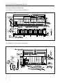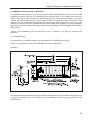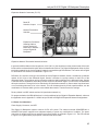
1
SLX200 Hardware User Manual isoLynxTM SLX200 Hardware User Manual isoLynxTM SLX200 Hardware User Manual MA1024 Rev. A – April 2005 © 2005 Dataforth Corporation. All Rights Reserved. The information in this manual is subject to change without notice, has been checked carefully, and is believed to be accurate; however, Dataforth assumes no responsibility for possible inaccuracies or omissions. Specifications are subject to change without notice. The information, tables, diagrams, and photographs contained herein are the property of Dataforth Corporation. No part of this manual may be reproduced or distributed by any means, electronic, mechanical, or otherwise, for any purpose other than the purchaser’s personal use, without the express written consent of Dataforth Corporation. isoLynx is a trademark of Dataforth Corporation. i isoLynx SLX200 Hardware User Manual ii Table of Contents 1.0 Inspection Guidelines ................................................................................................................................... 1 1.1 Unpacking ............................................................................................................................................. 1 1.2 isoLynx SLX200 Analog I/O Base Unit Package Contents ..................................................................... 1 1.3 Analog I/O Expansion Backpanels Package Contents ........................................................................... 2 1.4 isoLynx SLX101 Digital I/O Backpanel Package Contents ..................................................................... 3 2.0 System Overview .......................................................................................................................................... 5 2.1 Easy Installation .................................................................................................................................... 5 2.2 Easy Connectivity .................................................................................................................................. 5 3.0 Dimensions and Mounting Considerations .................................................................................................... 7 3.1 isoLynx SLX200 Analog I/O Base Unit ................................................................................................... 7 3.2 Analog I/O Expansion Backpanels ......................................................................................................... 8 3.3 isoLynx SLX101 Digital I/O Backpanel ................................................................................................... 9 4.0 isoLynx SLX200 Analog I/O Base Unit Description ..................................................................................... 11 4.1 isoLynx Controller ................................................................................................................................ 11 4.2 isoLynx SLX200 Analog I/O Base Unit Backpanel ................................................................................ 19 4.3 Functional Description ......................................................................................................................... 25 5.0 Analog I/O Expansion Backpanels Description ........................................................................................... 29 5.1 SCMPB02, 16-Position Analog I/O Backpanel ..................................................................................... 29 5.2 SCMPB06, 8-Position Analog I/O Backpanel ....................................................................................... 35 6.0 isoLynx SLX101 Digital I/O Backpanel Description ..................................................................................... 41 6.1 SCMD Modules ................................................................................................................................... 41 6.2 Expansion Considerations ................................................................................................................... 42 6.3 Power Considerations .......................................................................................................................... 43 6.4 Other Considerations ........................................................................................................................... 44 6.5 Functional Description ......................................................................................................................... 44 7.0 Computer - isoLynx Communications ......................................................................................................... 45 7.1 RS-232 Communications and Connections .......................................................................................... 45 7.2 RS-485 Communications and Connections .......................................................................................... 46 7.3 Ethernet Communications and Connections ......................................................................................... 47 7.4 Digital I/O Expansion Network Communications and Connections ....................................................... 47 7.5 The Hardware – Software Connection ................................................................................................... 48 Appendix A - Troubleshooting Guidelines ......................................................................................................... 49 A.1 isoLynx Controller A/D LED Blink Patterns .......................................................................................... 49 A.2 If the isoLynx Does Not Communicate or Sends Garbled Data From Any Interface .............................. 49 A.3 If in RS-485 the isoLynx Does Not Communicate or Sends Garbled Data ............................................ 50 A.4 If the isoLynx Is Communicating But Error Codes Persist .................................................................... 50 A.5 If the Digital I/O Backpanel Does Not Communicate or Sends Garbled Data ........................................ 50 Appendix B - Specifications, Factory Defaults, and Selection Guides .............................................................. 51 B.1 isoLynx SLX200 Analog I/O Base Unit ................................................................................................. 51 B.2 Analog I/O Expansion Backpanels ...................................................................................................... 52 B.3 SCM5B Selection Guide ...................................................................................................................... 53 B.4 LDM90 USB RS-232 Converter ............................................................................................................ 55 B.5 isoLynx SLX101 Digital I/O Backpanel ................................................................................................. 56 B.6 SCMD Selection Guide ....................................................................................................................... 56 iii isoLynx SLX200 Hardware User Manual Table of Contents (Continued) Appendix C - Ground Connections ................................................................................................................... 57 C.1 AN301 SCM5B-isoLynx Ground Connections ...................................................................................... 57 C.2 AN303 SCM5B Expansion Backpanel Ground Connections ................................................................ 58 Appendix D - AN302 isoLynx RS-485 and Digital I/O Expansion Network Configurations .................................. 59 Appendix E - Warranty, Disclaimers, Return/Repair Policy ............................................................................... 63 iv About This Manual This manual is organized as follows: • Chapter 1: Inspection Guidelines • Chapter 2: System Overview • Chapter 3: Dimensions and Mounting Considerations • Chapter 4: isoLynx SLX200 Analog I/O Base Unit Description • Chapter 5: Analog I/O Expansion Backpanels Description • Chapter 6: isoLynx SLX101 Digital I/O Backpanel Description • Chapter 7: Computer – isoLynx Communications Related Documents The following documents contain additional information: • isoLynx SLX200/101 Quick Start Guide • isoLynx SLX200 Software User Manual About Dataforth Corporation “Our passion at Dataforth Corporation is designing, manufacturing, and marketing the best possible signal conditioning and data communication products. Our mission is setting new standards of product quality, performance, and customer service.” Dataforth Corporation, with over 20 years experience, is the worldwide leader in Instrument ClassTM Industrial Electronics – rugged, high performance signal conditioning and data communication products that play a vital role in maintaining the integrity of industrial automation, data acquisition, and quality assurance systems. Our products directly connect to most industrial sensors and protect valuable measurement and control signals and equipment from the dangerous and degrading effects of noise, transient power surges, internal ground loops, and other hazards present in industrial environments. Dataforth spans the globe with over 50 International Distributors and US Representative Companies. Our customers benefit from a team of over 130 sales people highly trained in the application of precision products for industrial markets. In addition, we have a team of application engineers in our Tucson factory ready to address and solve any in-depth application questions. Upon receipt of a quote or order, our Customer Service Department provides fast one-day response of delivery information. We maintain an ample inventory that allows small quantity orders to be shipped from stock. Contacting Dataforth Corporation Contact Method Contact Information E-Mail: Technical Support: [email protected] Website: www.dataforth.com Phone: 520 741 1404 and 800 444 7644 Fax: 520 741 0762 Mail: Dataforth Corporation 3331 E. Hemisphere Loop Tucson, AZ 85706 Errata Sheets Refer to the Technical Support area of Dataforth’s web site ( www.dataforth.com) for any errata information on this product. v isoLynx SLX200 Hardware User Manual vi 1.0 Inspection Guidelines 1.1 Unpacking Each isoLynx SLX200 Analog I/O Base Unit is shipped in electro-static discharge (ESD) protective packaging. Use appropriate ESD protection measures while unpacking. Check visually for physical damage. If physical damage is noted, file a claim with the shipping carrier. 1.2 isoLynx SLX200 Analog I/O Base Unit Package Contents Figure 1.2-1 isoLynx SLX200 Analog I/O Base Unit comprised of: • isoLynx Controller (containing one SLX211 Processor Board, one I/O Signal Converter Board, and one optional Industrial Communication Board) mounted on the 12 channel Analog I/O Base Unit backpanel. Pictured in Figure 1.2-1 is a representative model of 8 models. • One CD-ROM containing isoLynx SLX200 data acquisition software drivers/examples and documentation files including: Help files, manuals, and specifications. • An isoLynx SLX200/101 Quick Start Guide. This completes the unpacking and visual inspection of the isoLynx SLX200 Analog I/O Base Unit. For rapid verification of basic functionality, reference the isoLynx SLX200/101 Quick Start Guide. For detailed configuration and installation in your system, reference the subsequent sections in this isoLynx SLX200 Hardware User Manual and/or the isoLynx SLX200 Software User Manual on CD-ROM. 1 isoLynx SLX200 Hardware User Manual 1.3 Analog I/O Expansion Backpanels Package Contents 1.3.1 SCMPB02, 16-Position Analog I/O Backpanel Figure 1.3.1-1 The SCMPB02 is shipped as a single fully assembled part. All backpanels include 16 analog I/O channel positions, 16 terminal blocks for field connections, expansion bus connectors, channel selection circuitry, address jumpers, power connection terminal block, power fuses, grounding options jumpers, and ground lug. Channel numbers 0 to 15 are printed on the board. Some options are: with or without cold junction compensation modules, with or without DIN Rail mounting brackets, depending on model ordered. 1.3.2 SCMPB06, 8-Position Analog I/O Backpanel Figure 1.3.2-1 The SCMPB06 is shipped as a single fully assembled part. All backpanels include 8 analog I/O channel positions, 8 terminal blocks for field connections, expansion bus connectors, channel selection circuitry, address jumpers, power connection terminal block, power fuses, grounding options jumpers, and ground lug. Channel numbers 0 to 7 are printed on the board. Some options are: with or without cold junction compensation modules, with or without DIN Rail mounting brackets, depending on model ordered. 2 Inspection Guidelines 1.4 isoLynx SLX101 Digital I/O Backpanel Package Contents Figure 1.4-1 • isoLynx SLX101 Digital I/O Backpanel, containing two high speed serial I/O ports and 16 digital I/O channel module sockets. Pictured in Figure 1.4-1 is a representative model of 2 models. This completes the unpacking and visual inspection of the isoLynx SLX101 Digital I/O Backpanel. For rapid verification of basic functionality, reference the isoLynx SLX200/101 Quick Start Guide. The scope of the isoLynx SLX200/101 Quick Start Guide covers rapid verification of the isoLynx SLX101 Digital I/O Backpanel connected to an isoLynx SLX200 Analog I/O Base Unit only. For detailed configuration and installation in your system, reference the subsequent sections in this isoLynx SLX200 Hardware User Manual and/or the isoLynx SLX200 Software User Manual on CD-ROM. 3 isoLynx SLX200 Hardware User Manual 4 2.0 System Overview The isoLynx SLX200 is a fast, intelligent, fully isolated data acquisition system providing superior reliability, accuracy, and isolation for a wide range of rugged industrial applications. The flexible, modular design combines a 12-channel I/O Controller base system and optional 8- and 16-channel expansion backpanels. One I/O Controller module can operate up to 60 channels of analog I/O and 128 channels of digital I/O, using Dataforth’s popular SCM5B analog and SCMD digital modules. The isoLynx SLX200 implements the industry standard Modbus RTU and TCP protocols, thereby enabling communication with a wide variety of existing third-party software drivers and HMI/SCADA packages. It is fully certified by the Modbus-IDA organization. The isoLynx uses RS-232/485 serial links up to 115.2kbps, and/or Ethernet as its physical layer. Standard communication is RS-232/485 and up to 32 systems can be multi-dropped on the RS-485 serial link. Optional fieldbus protocol communication boards are factory installed, but are field replaceable or upgradeable without processor hardware re-configuration. 2.1 Easy Installation The isoLynx’ compact footprint (17.4” x 3.5”) allows it to easily fit into cramped system designs. Using the SCMXRK metal bracket, you can easily mount it in a rack. Alternatively, by ordering DIN Rail hardware elements, you can just as easily mount it on a DIN Rail. 2.2 Easy Connectivity 2.2.1 RS-232 Connecting RS-232 is as easy as clicking an RJ-45 modular phone plug into a modular phone jack at the isoLynx end and then clicking an RJ-45 modular phone plug into a modular phone jack at the host computer end if so equipped. Alternatively, you can click the RJ-45 modular phone plug into a modular phone jack in a DB-9 connector adapter, subsequently, plugging the DB-9 connector end into the host computer port. Refer to section 7.1 RS-232 Communications and Connections for information on how this connector is wired. Also available from Dataforth is the LDM90 USB to RS-232 converter. Refer to Appendix B.4 for model numbers and descriptions. 2.2.2 RS-485 Connecting RS-485 is as easy as clicking an RJ-45 modular phone plug into a modular phone jack at the isoLynx end and then clicking an RJ-45 modular phone plug into a modular phone jack at the host computer end if so equipped. Alternatively, you can click the RJ-45 modular phone plug into a modular phone jack in a DB-9 connector adapter, subsequently, plugging the DB-9 connector end into the host computer port. If required by your installation, you will set a few termination DIP switches and then you will be off and communicating. Refer to section 7.2 RS-485 Communications and Connections for information on how this connector is wired. 2.2.3 Ethernet An Ethernet interface connection is one of the networking interfaces that can occupy the Industrial Communication Board position of the isoLynx Controller. Connecting to Ethernet is as easy as clicking an RJ-45 modular phone plug into a modular phone jack at the isoLynx end and then clicking an RJ-45 modular phone plug into a modular phone jack at the Ethernet hub or host computer if so equipped. Refer to section 7.3 Ethernet Communications and Connections for information on how this connector is wired. 5 isoLynx SLX200 Hardware User Manual 2.2.4 To Digital I/O Backpanels Connecting Digital I/O Backpanels is as easy as clicking an RJ-45 modular phone plug into a modular phone jack at the isoLynx end and then clicking an RJ-45 modular phone plug into a modular phone jack on the Digital I/O Backpanel. Refer to section 7.4 Digital I/O Expansion Network Communications and Connections for information on how this connector is wired. If required by your installation, you will set a few termination DIP switches and then you will be off and running digital I/O. Refer to section 4.1.3.2 Processor Board, Digital I/O Expansion Network Termination Network Switches and section 6.2 Expansion Considerations, Expansion Network Connectors (P1, P2) and Expansion Network Termination Network Switches. 2.2.5 To Analog I/O Expansion Backpanels Connecting Analog I/O Expansion Backpanels is as easy as setting a few address jumpers and then connecting an extension ribbon cable between the isoLynx SLX200 Analog I/O Base Unit Backpanel and the Analog I/O Expansion Backpanel. Refer to sections 5.1 SCMPB02, 16-Position Analog I/O Backpanel, and 5.2 SCMPB06, 8-Position Analog I/O Backpanel, for details. 6 3.0 Dimensions and Mounting Considerations The various models of the isoLynx system and expansion components have a choice of mounting options. Each can be mounted on a rack with the SCMXRK-002 19 inch metal mounting rack, onto a DIN Rail with available DIN Rail mounting elements, or through holes in swaged standoffs to a flat surface such as a NEMA-rated electrical enclosure. Sections 3.1 through 3.3 and their associated figures describe the isoLynx system and expansion components dimensions and mounting options. Select a mounting location that protects against the following environmental hazards: • Avoid flying metal chips that may result from installation or subsequent machine construction. Avoid conductive dusts, liquids, or condensing humidity. If any of these conditions exist, mount the isoLynx system and expansion components in a NEMA 4 or NEMA 12 rated enclosure. • Avoid mounting locations that are in close proximity to devices that produce Electro-Magnetic Interference (EMI) or Radio Frequency Interference (RFI). Devices such as motor starters, relays, large power transformers, and ultrasonic welding apparatus fall into this category. 6.850" (174.0) 9.500" (241.3) 13.200" (335.3) 0.150" (3.8) 3.050" (77.5) 3.470" (88.1) 0.210" (5.3) 1.275" (32.4) 0.210" (5.3) 3.1 isoLynx SLX200 Analog I/O Base Unit 17.100" (434.3) 17.400" (442.0) 0.150" (3.8) Overall Height: 3.330" (84.5) Dimensions in ( ) are mm. Figure 3.1-1 7 isoLynx SLX200 Hardware User Manual 3.2 Analog I/O Expansion Backpanels 3.2.1 SCMPB02, 16-Position Analog I/O Backpanel Figure 3.2.1-1 3.2.2 SCMPB06, 8-Position Analog I/O Backpanel Figure 3.2.2-1 8 Dimensions and Mounting Considerations 3.3 isoLynx SLX101 Digital I/O Backpanel Figure 3.3-1 9 isoLynx SLX200 Hardware User Manual 10 4.0 isoLynx SLX200 Analog I/O Base Unit Description 4.1 isoLynx Controller 4.1.1 Indicators and Connectors 4.1.1.1 Industrial Communication Board Ethernet - LEDs The Ethernet Board LEDs are: +5V, LNK, and ACT. The +5V LED indicates that the Ethernet board is properly powered with 5VDC. LNK indicates that the signal connected to the Ethernet board is an Ethernet signal and that it is a good connection. ACT indicates that the Ethernet link is active with data. Industrial Communication Board Ethernet - LEDs and Connector Figure 4.1.1.1-1 Ethernet - Connector The Ethernet connector is an RJ-45 modular phone jack. The Ethernet connection should always be made using a Category 5 twisted-pairs cable such as SLX141-xx, SLX141-Xxx, or equivalent. Refer to section 7.3 for pinout listings and more information on connectors and cabling for Ethernet. 11 isoLynx SLX200 Hardware User Manual 4.1.1.2 Processor Board LEDs The Processor Board LEDs are: +5V, RD, and TD. The +5V LED indicates that the Processor Board is properly powered with 5VDC. RD and TD indicate Receive Data and Transmit Data, respectively, for any serial I/O data communications. Processor Board - LEDs and Connectors Figure 4.1.1.2-1 Connectors The Processor Board connectors are: RS-232, RS-485, and isoLynx SLX101 Digital I/O Backpanel interface. All interface connectors are RJ-45 modular phone jacks. The RS-232 interface connection can be made using a variety of cables from 8-conductor flat cable through Category 3 to Category 5 twisted-pairs cable. The RS-485 and isoLynx SLX101 Digital I/O Backpanel Expansion Network connection can be made using Category 3 to Category 5 twisted-pairs cable. Dataforth offers SLX141-01,-02, and -07 Category 5 cable in three fixed lengths 1, 2, and 7 meters, respectively. Also available are the SLX142-P or –S RJ-45 (EIA-561) to DB-9 (EIA-574) RS-232 adapter and the SLX143-P or –S RJ-45 to DB-9 uncommitted adapter to be wired to the user’s DB-9 pinout. Refer to sections 7.1 and 7.2 for pinout listings for RS-232 and RS-485. Also available from Dataforth is the LDM90, USB to RS-232 converter. Refer to Appendix B.4 for model numbers and descriptions. 12 isoLynx SLX200 Analog I/O Base Unit Description 4.1.1.3 I/O Signal Converter Board LEDs I/O Signal Converter Board - LEDs Figure 4.1.1.3-1 The I/O Signal Converter Board LEDs are: +5V and A/D. The +5V LED indicates that the I/O Signal Converter Board is properly powered with 5VDC. The A/D LED indicates various states of operation of the isoLynx system. If the isoLynx micro controller detected a hardware failure during power on self test, the A/D LED signals the failure type through blink patterns. If the isoLynx hardware passed the power on self test, the A/D LED will blink at a steady rate. Appendix A.1 describes A/D LED blink patterns in greater detail. 13 isoLynx SLX200 Hardware User Manual 4.1.2 Opening the isoLynx Controller, Identifying Boards Figure 4.1.2-1 NOTE: A grounded static dissipative strap should be worn for this operation. Turn off power to the isoLynx SLX200 Analog I/O Base Unit Backpanel and disconnect all cables from the top of the isoLynx Controller. It may now be opened by removing the phillips flat head screws holding the top plate in place. There are six screws, four at the corners and two at the sides midway between the ends. Once the screws are removed lift the top plate carefully until it clears the connectors and LEDs. This will expose the boards inside. Figure 4.1.2-2 indicates the boards with names. Industrial Communication Board Processor Board I/O Signal Converter Board Figure 4.1.2-2 4.1.3 Removing and Replacing Boards NOTE: A grounded static dissipative strap should be worn for this operation. 14 isoLynx SLX200 Analog I/O Base Unit Description 4.1.3.1 Industrial Communication Board With the isoLynx SLX200 Analog I/O Base Unit in the same orientation as in Figure 4.1.2-1 grasp the left and right edges of the Industrial Communication Board and pull straight up until the board clears the top edge of the enclosure, any LEDs, and connectors. To replace, find the slot whose bus connectors on the backpanel match those on the Industrial Communication Board. Slide the board down the slot until the connectors just engage. Then push the board until the connectors fully engage. Figure 4.1.3.1-1 A description and photograph of the Ethernet Industrial Communication Board are here for completeness only. The board requires no user settings. The jumpers defining the network type are preset at the factory. Ethernet Field Installation Instructions NOTE: A grounded static dissipative strap should be worn for this operation. If at some point you decided to switch network types to Ethernet, you will have the SLX220 Ethernet Communication Board field install kit. At this point in the isoLynx SLX200 Hardware User Manual the isoLynx Controller top plate is off. If not, remove it. Find the slot whose bus connectors on the backpanel match those on the Industrial Communication Board (refer to Figure 4.1.2-1). Slide the board down the slot until the connectors just engage. Then push the board until the connectors fully engage. Use the top plate which is in the field install kit. This completes the SLX220 Ethernet Communication Board hardware field installation. Refer to the isoLynx SLX200 Software User Manual, “Modbus TCP Parameters” section, to configure the isoLynx System for Ethernet operation. 15 isoLynx SLX200 Hardware User Manual Ethernet Configuration Notes When the isoLynx has an Ethernet Industrial Communication Board installed, it will sense this upon power-up or for any other reset condition and boot up in Modbus TCP mode. The IP address, subnetmask, gateway, and dnsserver will be the last set configured by Modbus Write Single Register or Write Multiple Registers functions to the registers outlined in the isoLynx SLX200 Software User Manual, “Modbus TCP Parameters” section. The isoLynx will boot up in the factory default Ethernet configuration when powered up fresh from the factory, after cycling the “Communication Interface Reset Jumper”, or after a write to the Modbus TCP Parameters registers which explicitly reset all Ethernet parameters. The factory default Ethernet parameters are: Parameter Decimal Value Hex Value IP address subnetmask gateway TCP Port Keep alive timeout 192.168.0.215 255.255.255.0 127.0.0.1 502 7200 seconds C0.A8.00.D7 FE.FE.FE.00 7F.00.00.01 If for any reason you need to use RS-232 to communicate with the isoLynx, remove the Ethernet Industrial Communication Board using the instructions in section 4.1.3 “Removing and Replacing Boards” in this manual. Then power up and cycle the communication interface reset jumper using the instructions in section 4.2.6 “Other Considerations - Communications Interface Reset Jumper” also in this manual. 16 isoLynx SLX200 Analog I/O Base Unit Description 4.1.3.2 Processor Board Modbus RTU Slave ID Selection The jumpers outlined in Figure 4.1.3.2-1 to the right of the E1 and E2 jumpers select the lower four bits of the Modbus RTU Slave ID. There are four jumpers which allow for 16 addresses. The LSB (Least Significant Bit) of the address lines is the jumper designated LSB on the board. A jumper over both pins of any jumper position corresponds to a 0 (zero) in the address and an open (a jumper over one pin) in any jumper position corresponds to a 1 (one) in the address. To obtain the lower four bits of a particular slave ID, just arrange jumpers in the binary weighted pattern of the value desired. The factory default setting is all jumpers open. Modbus RTU Slave ID Lower Four Bits Figure 4.1.3.2-1 The upper four bits are stored in the Processor Board non-volatile memory and may be changed by writing the appropriate register location, refer to the isoLynx SLX200 Software User Manual, “Modbus RTU Parameter Register Locations” section. The factory default setting for the upper four bits is 0001. The resulting factory default Slave ID is 31 (0x1F). The following table shows the factory default settings of the Modbus RTU communications parameters. Parameter Factory Default Setting Serial Interface Data Rate Parity Slave ID RS-232 19200bps (bits per second) Even 31 (0x1F) 17 isoLynx SLX200 Hardware User Manual RS-485 and Digital I/O Termination Networks Setting With the isoLynx SLX200 Analog I/O Base Unit in the same orientation as in Figure 4.1.2-1 grasp the left and right edges including the RJ-45 connector of the Processor Board and pull straight up until the board clears the top edge of the enclosure, any LEDs, and connectors. To replace, find the slot whose bus connectors on the backpanel match those of the Processor Board. Slide the board down the slot until the connectors just engage. Then push the board until the connectors fully engage. RS-485 Termination Networks Switches In general for RS-485 for trunk line lengths over 100 ft (30.5 m), the two devices at the extreme ends of the trunk line should be terminated and all other devices in between should not. The Processor Board offers built-in termination networks for 2-wire or 4-wire networks accessed through DIP switches. The location of the RS-485 termination DIP switches are identified in Figure 4.1.3.2-2. Two-wire Networks DIP switch, S1, sections 1 through 3 are used for 2-wire networks and sections 4 through 6 should be switched off (the actuators away from ON). Section 1 switches in a pull-down resistor for the A line of the differential signal. Section 3 switches in a pull-up resistor for the B line of the differential signal. The pull-down pull-up network provides the idle line biasing for the RS-485 input. Section 2 switches the line impedance terminating resistor across the differential signal. In most cases, the installation will require sections 1 through 3 all to be switched to ON (termination network in). Some cases may allow fewer or no terminating elements to be in the network. This can be determined by a little experimentation; use the combination of elements which give the most reliable data transfer. Then document the settings. The factory default settings are: sections 1 through 3 are ON and sections 4 through 6 are OFF. These are also the end of trunk line settings for RS-485 2-wire networks. 18 isoLynx SLX200 Analog I/O Base Unit Description For proper termination of all RS-485 devices in a 2-wire multidrop network, reference the application note in Appendix D - AN302 isoLynx RS-485 and Digital I/O Expansion Network Configurations. RS-485 Termination Switches (Reference Section 4.1.3.2 Processor Board RS-485 Termination Networks Switches) Digital I/O Network Termination Switches (Reference Section 4.1.3.2 Processor Board Digital I/O Expansion Network Termination Network Switches) Figure 4.1.3.2-2 Four-wire Networks DIP switch, S1, sections 2, 4, 5, and 6 are used for 4-wire networks and sections 1 and 3 should be switched off (the actuators away from ON). Section 2 switches the line impedance terminating resistor across the Transmit Data (TD) differential signal. Section 4 switches in a pull-down resistor for the A line of the differential signal. Section 6 switches in a pull-up resistor for the B line of the differential signal. The pull-down pull-up network provides the idle line biasing for the RS-485 input. Section 5 switches the line impedance terminating resistor across the differential signal. In most cases, the installation will require sections 2, 4, 5, and 6 all to be switched to ON (termination network in). Some cases may allow fewer or no terminating elements to be in the network. This can be determined by a little experimentation; use the combination of elements which give the most reliable data transfer. Most installations will require the terminating resistor in section 5 because it terminates the receiver which is the most sensitive node. Then document the settings. The factory default settings are: sections 1 through 3 are ON and sections 4 through 6 are OFF. These are also the end of trunk line settings for RS-485 2-wire networks. For proper termination of all RS-485 devices in a 4-wire multidrop network, reference the application note in Appendix D - AN302 isoLynx RS-485 and Digital I/O Expansion Network Configurations. Digital I/O Expansion Network Termination Network Switches In general for differential trunk line lengths over 100 ft (30.5 m), the two devices at the extreme ends of the trunk line should be terminated and all other devices in between should not. The Processor Board offers a built-in termination network for the 2-wire Digital I/O network accessed through DIP switches. The location of the Digital I/O termination DIP switches are identified in Figure 4.1.3.2-2. DIP switch, S2, sections 1 through 3 are used for the 2-wire Digital I/O expansion network. Section 1 switches in a pull-down resistor for the A line of the differential signal. Section 2 switches in a pull-up resistor for the 19 isoLynx SLX200 Hardware User Manual B line of the differential signal. The pull-down pull-up network provides the idle line biasing for the differential input. Section 3 switches the line impedance terminating resistor across the differential signal. In most cases, the installation will require sections 1 through 3 all to be switched to ON (termination network in). Some cases may allow fewer or no terminating elements to be in the network. This can be determined by a little experimentation; use the combination of elements which give the most reliable data transfer. Then document the settings. The factory default settings are: sections 1 through 3 are ON. These are also the end of trunk line settings for RS-485 2-wire networks. For proper termination of all RS-485 devices in a 2-wire multidrop isoLynx Digital I/O Expansion Network, reference the application note in Appendix D - AN302 isoLynx RS-485 and Digital I/O Expansion Network Configurations. 4.1.3.3 I/O Signal Converter Board With the isoLynx SLX200 Analog I/O Base Unit in the same orientation as in Figure 4.1.2-1 grasp the left and right edges of the I/O Signal Converter Board and pull straight up until the board clears the top edge of the enclosure, any LEDs, and connectors. To replace, find the slot whose bus connectors on the backpanel match those of the I/O Signal Converter Board. Slide the board down the slot until the connectors just engage. Then push the board until the connectors fully engage. Figure 4.1.3.3-1 A description and photograph of the I/O Signal Converter Board are here for completeness only. The board requires no user adjustments. All trimpot adjustments are made for the requirements of the particular circuit component mix at the factory. 20 isoLynx SLX200 Analog I/O Base Unit Description 4.2 isoLynx SLX200 Analog I/O Base Unit Backpanel 4.2.1 SCM5B Modules Installation Vacant Channel Position Showing Sockets Orientation (Reference Section 4.2.1 SCM5B Modules Installation) Populated Channel Position Showing Module Orientation (Reference Section 4.2.1 SCM5B Modules Installation) Figure 4.2.1-1 Each channel position on the backpanel has 14 sockets and a threaded insert. An SCM5B module plugs in only one way into the socket pattern. The module has a captive fastening screw which may be tightened into the threaded insert. Wiring Field connections are made through the screw terminal blocks in front of the channel positions on the backpanel (TB1 – TB12). Figure 4.2.1-2 schematic shows the functions of the electrical connections. Figure 4.2.1-2 21 isoLynx SLX200 Hardware User Manual 4.2.2 Modbus Slave ID Selection The information in this section (4.2.2) is here for completeness and to show the physical location of the lower four bits of the Modbus Slave ID jumpers on the isoLynx SLX200 Base Unit Backpanel. To obtain complete physical and logical instructions for selecting a Slave ID, refer to section 4.1.3.2 Processor Board, subsection Modbus Slave ID Selection. Figure 4.2.2-1 is replicated in section 4.1.3.2 as Figure 4.1.3.2-1. The jumpers outlined in Figure 4.2.2-1 to the right of the E1 and E2 jumpers select the lower four bits of the Modbus RTU Slave ID. There are four jumpers which allow for 16 addresses. The LSB (Least Significant Bit) of the address lines is the jumper designated LSB on the board. A jumper over both pins of any jumper position corresponds to a 0 (zero) in the address and an open (a jumper over one pin) in any jumper position corresponds to a 1 (one) in the address. To obtain a particular Slave ID, just arrange jumpers in the binary weighted pattern of the value desired. The factory default setting is all jumpers open. Expansion Mode Selection Jumpers Expansion Connector and Cable Modbus Slave ID Lower Four Bits Figure 4.2.2-1 4.2.3 Expansion Considerations Expansion Mode Selection The isoLynx SLX200 Analog I/O Base Unit Backpanel has address decoding circuitry to allow multiplexing up to 12 input or output modules (See Appendix B.3 SCM5B Selection Guide and NOTES at end). Capability is also provided in the address decode circuitry to expand the system to 60 channels (one isoLynx SLX200 Analog I/O Base Unit Backpanel + three SCMPB02/06 backpanels) of multiplexed input or output. The isoLynx SLX200 Analog I/O Base Unit always resides at the base addresses 0-11. Therefore, E1 and E2 have only two positions each, one for stand alone operation and one for expanded operation. Channels 12-15 are not available in an isoLynx system. 22 isoLynx SLX200 Analog I/O Base Unit Description The table below shows the correlation of jumper position to address range. The factory default settings are: E1, 4 is open and 0 is set; E2, 4 is open and 0 is set. E1 Jumper Pos 4 0 E2 Jumper Pos 4 0 Address Range/Mode Channel ID’s 0-11, Panel 0/Stand Alone Channel ID’s 0-11, Panel 0/Expanded To connect to multiple SCMPB02/06 backpanels in this expanded configuration, use interconnect cable SCMXCA004-XX. Refer to sections 5.1.2 and 5.2.2 for details on SCMPB02 and SCMPB06 expansion procedures. Expansion Connector (P6) The 26 pin connector P6 provides the signal interface between the isoLynx SLX200 Analog I/O Base Unit Backpanel and the SCMPB02/06 backpanels. Two separate analog buses are provided; one for analog input signals and one for analog output signals. Two sets of six address lines and an enable pin allow input and output modules to be independently multiplexed onto their respective analog signal bus. R0 thru R5 and RD EN\ are used for input modules, and W0 thru W5 and WR EN\ are used for output modules. 4.2.4 Grounding Considerations Backpanel Jumpers Grounding Jumpers and Resistor Figure 4.2.4-1 For proper operation of the output switch or track-and-hold circuit when using the isoLynx SLX200 Analog I/O Base Unit Backpanel, a current path must exist between the host control logic power common and module I/O Common (module pin 19). This path can be established on the isoLynx SLX200 Analog I/O Base Unit Backpanel via jumper J4. If this connection exists elsewhere in the system, jumper J4 should be removed since possible ground loops could exist. Other connections of power ground and signal ground usually occur at the A/D or D/A converter of the host measurement system. More information on grounding can be found in Appendix C.1 - AN301 SCM5B-isoLynx Ground Connections. 23 isoLynx SLX200 Hardware User Manual If the connection of power common and SIG COM shield wires exist in the host measurement system, a resistive connection between SIG COM and the backpanel signal ground can be made via R1. R1 can be as large as 10K ohms; 100 ohms is a recommended value. Factory default settings are: R1=100 ohms; J1, J2, and J4 installed; and J3 not installed. Grounding Stud Grounding Stud Figure 4.2.4-2 For full protection against large electrical disturbances on the field-side of the SCM5B modules, a #10-32 ground stud is provided on the backpanel. An electrical connection between this ground stud and system ground should be provided with a large gauge wire of the shortest possible length. When this connection is made, a possible ground loop could result through the SIG COM shield wires and backpanel signal ground. If the application involves only input modules and a differential input is used by the host measurement system, J1 should be removed. Remember that J1 is required if output modules are used or if the host system does not have differential inputs. 24 isoLynx SLX200 Analog I/O Base Unit Description 4.2.5 Power Considerations Power Supply, Connector, and LED The isoLynx SLX200 Analog I/O Base Unit Backpanel requires external +5VDC ±5% power. The chassis mounted SLX160 power supply has adequate capacity to power any combination of modules. The power connection is made through the two position screw terminal block as shown in Figure 4.2.5-1. The LED shown in Figure 4.2.5-1 lights when a proper power connection has been made. Power Screw Terminal Block Power Indicator LED Power Fuse Figure 4.2.5-1 Fusing The isoLynx SLX200 Analog I/O Base Unit Backpanel power is fuse protected through F1 shown in Figure 4.2.5-1. This is a Littelfuse type 252007, 7 amp fuse. Zener diode D1 provides extra protection by clamping the input power voltage to +5.6V. If the input supply voltage connection is reversed, this zener diode will be forward biased and fuse F1 will be blown. 25 isoLynx SLX200 Hardware User Manual 4.2.6 Other Considerations Communication Interface Reset Jumper Communication Interface Reset Jumper Figure 4.2.6-1 For situations in which an isoLynx has unknown communications parameters, a hardware reset jumper has been provided. This jumper is near the jumpers labeled “ADDR” as shown in Figure 4.2.6-1. Opening the header pins momentarily with the mini-link shunt jumper provided, resets all isoLynx communications parameters to factory default settings. The shunt jumper must be re-installed over both pins and left there for the reset to complete and for continuous operation to begin. This function is one of the troubleshooting guidelines discussed in Appendix A – Troubleshooting. Refer to the communications interface type subsection of section 4.1.3.1 “Industrial Communication Board” for the particular factory default settings. 26 isoLynx SLX200 Analog I/O Base Unit Description 4.3 Functional Description 4.3.1 Industrial Communication Board Ethernet The Industrial Communication Board together with the 10Base-T Ethernet module serve as the interface to an 10Base-T Ethernet or a 10/100Base-T network. The Industrial Communication Board communicates internally with the Processor Board over a serial data link. 4.3.2 Processor Board The Processor Board serves as the central controller for the isoLynx system. Its functions include data communications for receiving, interpreting, and executing functions, storing and manipulating data and configuration parameters; commanding configuration changes to the hardware; communicating with the Digital I/O Backpanels; and gathering and communicating data and status to the host computer. 4.3.3 I/O Signal Converter Board The I/O Signal Converter Board serves as the central data conversion function for both input and output signals. It also has the ability to read a ground reference and a voltage reference for internal calibration purposes. 4.3.4 Analog I/O Base Unit Backpanel The Analog I/O Base Unit Backpanel serves as the hardware “glue” for the isoLynx system. It is the carrier for the isoLynx function boards and as well as up to 12 SCM5B analog I/O modules. It is also the central connection point for expansion backpanels, their associated signals, and grounding configuration for the system. The Analog I/O Base Unit Backpanel has two analog buses; one for analog input and one for analog output. This two-bus configuration takes advantage of the switch controlled outputs on the input modules and the track-and-hold inputs on the output modules. The backpanel address jumpers E1,E2 determine whether the backpanel will function in standalone or expansion mode. The addressing decoder circuitry allows a controller to select any channel in the address space. An optional temperature sensor is mounted on each channel to provide cold junction compensation for thermocouple input modules. 27 isoLynx SLX200 Hardware User Manual 28 5.0 Analog I/O Expansion Backpanels Description 5.1 SCMPB02, 16-Position Analog I/O Backpanel The SCMPB02 backpanel (Figure 5.1.1-1) can accept up to 16 SCM5B modules. It can be mounted on the SCMXRK-002 19-inch metal rack. The SCMPB02 has two analog buses; one for analog input and one for analog output. This two-bus configuration takes advantage of the switch controlled outputs on the input modules and the track-and-hold inputs on the output modules. A temperature sensor is mounted on each channel to provide cold junction compensation for thermocouple input modules (See Figure 5.1.1-2 for schematic). Field connections are terminated with four screw terminals at each module site. Up to three SCMPB02 backpanels may be daisy-chained to the isoLynx SLX200 Analog I/O Base Unit. Use SCMXCA004-XX cable for daisy chaining. 5.1.1 SCM5B Modules For an extensive list of available modules, refer to Appendix B.3, SCM5B Selection Guide. NOTE: For isoLynx system exceptions, see NOTES at the end of Appendix B.3. Installation Figure 5.1.1-1 Each channel position on the backpanel has 14 sockets and a threaded insert. An SCM5B module plugs in only one way into the socket pattern. The module has a captive fastening screw which may be tightened into the threaded insert. 29 isoLynx SLX200 Hardware User Manual Wiring Figure 5.1.1-2 Field connections are made through the screw terminal blocks in front of the channel positions on the backpanel (TB1 – TB16). Figure 5.1.1-2 schematic shows the functions of the electrical connections. 30 Analog I/O Expansion Backpanels Description 5.1.2 Expansion Considerations Address Selection Expansion Connectors and Cable Address Selection Jumpers Figure 5.1.2-1 The SCMPB02 backpanel has address decoding circuitry to allow multiplexing up to 16 input or output modules (See Appendix B.3 SCM5B Selection Guide and NOTES at end). Capability is also provided in the address decode circuitry to expand the system to 60 channels (three SCMPB02 backpanels + one isoLynx SLX200 Analog I/O Base Unit) of multiplexed input or output. Jumpers on HD10 header, E1 and E2 group, select which set of 16 addresses are assigned to a particular backpanel. The E1 group assigns a set of 16 addresses for input modules, and the E2 group assigns a set of 16 addresses for output modules. Channels 12-15 are not available in an isoLynx system. The table below shows the correlation of jumper position to address range. The factory default settings are: E1, 4 through 1 are open and 0 is set; E2, 4 through 1 are open and 0 is set. E1 Jumper Pos 4 E2 Jumper Pos 4 3 2 1 0 3 2 1 0 Address Range/Mode Channel ID’s 0-15/Stand Alone NOT USED WITH isoLynx Channel ID’s 48-63, Panel 3/Expanded Channel ID’s 32-47, Panel 2/Expanded Channel ID’s 16-31, Panel 1/Expanded Channel ID’s 0-15/Expanded NOT USED WITH isoLynx To connect multiple SCMPB02 backpanels in this expanded configuration, use interconnect cable SCMXCA004-XX. Refer to sections 4.2.3 and 5.2.2 for details on isoLynx SLX200 Analog I/O Base Unit Backpanel and SCMPB06 Backpanel expansion procedures. 31 isoLynx SLX200 Hardware User Manual Expansion Connectors (P1, P2) The 26 pin connectors P1 and P2 provide the signal interface between the SCMPB02 backpanel and the isoLynx System. Two separate analog buses are provided; one for analog input signals and one for analog output signals. Two sets of six address lines and an enable pin allow input and output modules to be independently multiplexed onto their respective analog signal bus. R0 thru R5 and RD EN\ are used for input modules, and W0 thru W5 and WR EN\ are used for output modules. 5.1.3 Grounding Considerations Backpanel Jumpers Grounding Jumpers and Resistor Figure 5.1.3-1 For proper operation of the output switch or track-and-hold circuit when using the SCMPB02/06 backpanels, a current path must exist between the host control logic power common and module I/O Common (module pin 19). This path can be established on the SCMPB02 via jumper J4. If this connection exists elsewhere in the system, jumper J4 should be removed since possible ground loops could exist. Other connections of power ground and signal ground usually occur at the A/D or D/A converter of the host measurement system. More information on grounding can be found in Appendix C.2 - AN303 SCM5B Expansion Backpanel Ground Connections. If the connection of power common and SIG COM shield wires exist in the host measurement system, a resistive connection between SIG COM and the backpanel signal ground can be made via R1. R1 can be as large as 10K ohms; 100 ohms is a recommended value. Factory default settings are: R1=100 ohms; J1, J2, and J4 installed; and J3 not installed. 32 Analog I/O Expansion Backpanels Description Grounding Stud Grounding Stud Figure 5.1.3-2 For full protection against large electrical disturbances on the field-side of the SCM5B modules, a #10-32 ground stud is provided on the backpanel. An electrical connection between this ground stud and system ground should be provided with a large gauge wire of the shortest possible length. When this connection is made, a possible ground loop could result through the SIG COM shield wires and backpanel signal ground. If the application involves only input modules and a differential input is used by the host measurement system, J1 should be removed. Remember that J1 is required if output modules are used or if the host system does not have differential inputs. 33 isoLynx SLX200 Hardware User Manual 5.1.4 Power Considerations Power Supply, Connector, and LED The SCMPB02 backpanel requires external +5VDC ±5% power. The chassis mounted SCMXPRE-003 or SCMXPRT-003 power supplies have adequate capacity to power any combination of modules. The power connection is made through the two position screw terminal block as outlined in Figure 5.1.4-1. The LED outlined in Figure 5.1.4-1 lights when a proper power connection has been made. Power Screw Terminal Block Power Indicator LED Power Fuse Figure 5.1.4-1 Fusing The SCMPB02 backpanel power is fuse protected through F1 outlined in Figure 5.1.4-1. This is a Littelfuse type 252004, 4 amp fuse. Zener diode D1 provides extra protection by clamping the input power voltage to +5.6V. If the input supply voltage connection is reversed, this zener diode will be forward biased and fuse F1 will be blown. 5.1.5 Functional Description The SCMPB02 has two analog buses; one for analog input and one for analog output. This two-bus configuration takes advantage of the switch controlled outputs on the input modules and the track-and-hold inputs on the output modules. The address jumpers determine where in the address space an individual backpanel will reside. The address decoding circuitry allows a controller to select any channel in the address space. A temperature sensor is mounted on each channel to provide cold junction compensation for thermocouple input modules. 34 Analog I/O Expansion Backpanels Description 5.2 SCMPB06, 8-Position Analog I/O Backpanel The SCMPB06 backpanel (Figure 5.2.1-1) can accept up to eight SCM5B modules. It can be mounted on the SCMXRK-002 19-inch metal rack. The SCMPB06 has two analog buses; one for analog input and one for analog output. This two-bus configuration takes advantage of the switch controlled outputs on the input modules and the track-and-hold inputs on the output modules. A temperature sensor is mounted on each channel to provide cold junction compensation for thermocouple input modules (See Figure 5.2.1-2 for schematic). Field connections are terminated with four screw terminals at each module site. Up to six SCMPB06 backpanels may be daisy-chained to the isoLynx SLX200 Analog I/O Base Unit. Use SCMXCA004-XX cable for daisy chaining. Jumpers on the SCMPB06 permit user selection of low (i.e. channels 0-7) or high (i.e. channels 8-15) addresses. 5.2.1 SCM5B Modules For an extensive list of available modules, refer to Appendix B.3, SCM5B Selection Guide. NOTE: For isoLynx system exceptions, see NOTES at the end of Appendix B.3. Installation Figure 5.2.1-1 Each channel position on the backpanel has 14 sockets and a threaded insert. An SCM5B module plugs in only one way into the socket pattern. The module has a captive fastening screw which may be tightened into the threaded insert. 35 isoLynx SLX200 Hardware User Manual Wiring Figure 5.2.1-2 Field connections are made through the screw terminal blocks in front of the channel positions on the backpanel (TB1 – TB8). Figure 5.2.1-2 schematic shows the functions of the electrical connections. 36 Analog I/O Expansion Backpanels Description 5.2.2 Expansion Considerations Address Selection Address Selection Jumpers Expansion Connectors and Cable Figure 5.2.2-1 The SCMPB06 backpanel has address decoding circuitry to allow multiplexing up to 8 input or output modules (See Appendix B.3 SCM5B Selection Guide and NOTES at end). Capability is also provided in the address decode circuitry to expand the system to 60 channels (six SCMPB06 backpanels + one isoLynx SLX200 Analog I/O Base Unit) of multiplexed input or output. Jumpers select which set of 16 addresses are assigned to a particular backpanel. Channels 12-15 are not available in an isoLynx system. The table below shows the correlation of jumper position to address range. The factory default settings are: E1, 4 through 1 are open and 0 is set; E2, 4 through 1 are open and 0 is set. Read Address Jumper (E1) 1 2 3 4 5 Write Address Jumper (E2) 6 7 8 9 10 Address Range/Mode Channel ID’s 0-15/Stand Alone NOT USED WITH isoLynx Channel ID’s 48-63, Panel 3/Expanded Channel ID’s 32-47, Panel 2/Expanded Channel ID’s 16-31, Panel 1/Expanded Channel ID’s 0-15/Expanded NOT USED WITH isoLynx Module read and write addresses may be selected as low (channels 0-7) or high (channels 8-15) using the four sets of 3 position jumpers labeled J5 through J8. Place a jumper over the two pins furthest from the field I/O termination blocks on all four sets to select a low address (factory configuration) or over the two pins closest to the field I/O termination blocks on all four sets to select a high address. The factory default settings are: J5 through J8, HI are open and LO are set. To connect multiple SCMPB06 backpanels in this expanded configuration, use interconnect cable SCMXCA004-XX. Refer to sections 4.2.3 and 5.1.2 for details on isoLynx SLX200 Analog I/O Base Unit Backpanel and SCMPB02 Backpanel expansion procedures. 37 isoLynx SLX200 Hardware User Manual Expansion Connectors (P1, P2) The 26 pin connectors P1 and P2 provide the signal interface between the SCMPB06 backpanel and the isoLynx System. Two separate analog buses are provided; one for analog input signals and one for analog output signals. Two sets of six address lines and an enable pin allow input and output modules to be independently multiplexed onto their respective analog signal bus. R0 thru R5 and RD EN\ are used for input modules, and W0 thru W5 and WR EN\ are used for output modules. 5.2.3 Grounding Considerations Backpanel Jumpers Grounding Jumpers and Resistor Figure 5.2.3-1 For proper operation of the output switch or track-and-hold circuit when using the SCMPB02/06 backpanels, a current path must exist between the host control logic power common and module I/O Common (module pin 19). This path can be established on the SCMPB06 via jumper J4. If this connection exists elsewhere in the system, jumper J4 should be removed since possible ground loops could exist. Other connections of power ground and signal ground usually occur at the A/D or D/A converter of the host measurement system. More information on grounding can be found in Appendix C.2 - AN303 SCM5B Expansion Backpanel Ground Connections. If the connection of power common and SIG COM shield wires exist in the host measurement system, a resistive connection between SIG COM and the backpanel signal ground can be made via R1. R1 can be as large as 10K ohms; 100 ohms is a recommended value. Factory default settings are: R1=100 ohms; J1, J2, and J4 installed; and J3 not installed. 38 Analog I/O Expansion Backpanels Description Grounding Stud Grounding Stud Figure 5.2.3-2 For full protection against large electrical disturbances on the field-side of the SCM5B modules, a #10-32 ground stud is provided on the backpanel. An electrical connection between this ground stud and system ground should be provided with a large gauge wire of the shortest possible length. When this connection is made, a possible ground loop could result through the SIG COM shield wires and backpanel signal ground. Remember that J1 is required. 39 isoLynx SLX200 Hardware User Manual 5.2.4 Power Considerations Power Supply, Connector, and LED The SCMPB06 backpanel requires external +5VDC ±5% power. The chassis mounted SCMXPRE-003 or SCMXPRT-003 power supplies have adequate capacity to power any combination of modules. The power connection is made through the two position screw terminal block as outlined in Figure 5.2.4-1. The LED outlined in Figure 5.2.4-1 lights when a proper power connection has been made. Power Screw Terminal Block Power Indicator LED Power Fuse Figure 5.2.4-1 Fusing The SCMPB06 backpanel power is fuse protected through F1 outlined in Figure 5.2.4-1. This is a Littelfuse type 252004, 4 amp fuse. Zener diode D1 provides extra protection by clamping the input power voltage to +5.6V. If the input supply voltage connection is reversed, this zener diode will be forward biased and fuse F1 will be blown. 5.2.5 Functional Description The SCMPB06 has two analog buses; one for analog input and one for analog output. This two-bus configuration takes advantage of the switch controlled outputs on the input modules and the track-and-hold inputs on the output modules. The address jumpers determine where in the address space an individual backpanel will reside. The addressing decoder circuitry allows a controller to select any channel in the address space. Additionally, since each SCMPB06 can accommodate only 8 modules, module read and write addresses may be selected as low (channels 0-7) or high (channels 8-15). A temperature sensor is mounted on each channel to provide cold junction compensation for thermocouple input modules. 40 6.0 isoLynx SLX101 Digital I/O Backpanel Description 6.1 SCMD Modules For an extensive list of available modules, refer to Appendix B.6, SCMD Selection Guide. Installation LEDs Show Logic State Installed Module Showing Orientation Vacant Channel Showing Socket Location, Orientation, and Locating Hole Position Figure 6.1-1 Each channel position on the backpanel has 5 sockets and a threaded insert. An SCMD module plugs in only one way into the socket pattern. The module has a locating peg or screw which slides or threads into the threaded insert. LEDs Each channel has an LED near the channel module position. The LED indicates the logic state of the channel input or output. When the LED is on, the input or output function is asserted. When the LED is off, the input or output function is disasserted. 41 isoLynx SLX200 Hardware User Manual Wiring Field connections are made through the screw terminal blocks behind the channel positions on the backpanel (1 – 32). Figure 6.1-2 shows the polarity of the field connections. Typical Field Wiring Fuse Typical Screw Terminal Block Field Connection Showing Signal Polarity + Figure 6.1-2 Fusing Each channel has a replaceable fuse between the module and the field wiring screw terminal blocks. A spare fuse is located between the terminal blocks for channel 7 (terminal 16) and 8 (terminal 17). 6.2 Expansion Considerations Digital I/O Panel ID Selection The jumpers outlined in Figure 6.2-1 select the Digital I/O Backpanel’s Panel ID in a multidropped Digital I/O Expansion Network (for more on this, refer to Expansion Network Termination Network Switches below and Appendix D). There is a three jumper group, J1, which allows for 8 Panel ID’s. The LSB (Least Significant Bit) of the address lines is the jumper designated as LSB on the board. A jumper over both pins of any jumper position corresponds to a 0 (zero) in the Panel ID and an open (a jumper over one pin) in any jumper position corresponds to a 1 (one) in the Panel ID. To obtain a particular Panel ID, just arrange jumpers in the binary weighted pattern of the hexadecimal value desired. Factory default is all jumpers are set (Panel ID 0). 42 isoLynx SLX101 Digital I/O Backpanel Description Expansion Network Connectors (P1, P2) Panel ID Selection Jumper Network Termination Switches Expansion Connectors Showing Cable to isoLynx Analog I/O Base Unit or Another isoLynx Digital I/O Backpanel Figure 6.2-1 Expansion Network Termination Network Switches In general for differential trunk line lengths over 100 ft (30.5 m), the two devices at the extreme ends of the trunk line should be terminated and all other devices in between should not. The Digital I/O Backpanel offers a built-in termination network for the 2-wire Digital I/O network accessed through DIP switches. The location of the Digital I/O termination DIP switches are identified in Figure 6.2-1. DIP switch, S1, sections 1 through 3 are used for the 2-wire Digital I/O network. Section 1 switches in a pull-down resistor for the A line of the differential signal. Section 3 switches in a pull-up resistor for the B line of the differential signal. The pull-down pull-up network provides the idle line biasing for the differential input. Section 2 switches the line impedance terminating resistor across the differential signal. In most cases, the installation will require sections 1 through 3 all to be switched to ON (termination network in). Some cases may allow fewer or no terminating elements to be in the network. This can be determined by a little experimentation; use the combination of elements which give the most reliable data transfer. Then document the settings. Factory default is all DIP switch sections ON (termination network in). For proper termination of all RS-485 devices in a 2-wire multidrop isoLynx Digital I/O Expansion Network, reference the application note in Appendix D - AN302 isoLynx RS-485 and Digital I/O Expansion Network Configurations. 6.3 Power Considerations Power Supply, Connector, and LED The Digital I/O Backpanel requires external +5VDC ±5% power. The chassis mounted SCMXPRE-003 or SCMXPRT-003 power supplies have adequate capacity to power any combination of modules. The power connection is made through the two position screw terminal block as outlined in Figure 6.3-1. The LED outlined in Figure 6.3-1 lights when a proper power connection has been made. 43 isoLynx SLX200 Hardware User Manual Power Indicator LED Communications Reset Jumper Power Fuse Power Screw Terminal Block Figure 6.3-1 Fusing The Digital I/O Backpanel power is fuse protected through F17 outlined in Figure 6.3-1. This is a 4 amp fuse. A Zener diode provides extra protection by clamping the input power voltage to +5.6V. If the input supply voltage connection is reversed, this zener diode will be forward biased and fuse F17 will be blown. 6.4 Other Considerations Communications Reset Jumper For situations in which the Digital I/O Backpanel to be installed has an unknown data rate, a hardware reset jumper has been provided. This jumper is near the termination network DIP switch as outlined in Figure 6.3-1. Opening the header pins momentarily with the mini-link shunt jumper provided, resets the Digital I/O Backpanel data rate to 115.2K bits per second (bps)(Baud). The shunt jumper must be re-installed over both pins and left there for the reset to complete and for continuous operation to begin. This function is one of the troubleshooting guidelines discussed in Appendix A – Troubleshooting. The factory default setting is the jumper is set. 6.5 Functional Description The Digital I/O Backpanel serves as the carrier for the digital I/O microcontroller, the digital I/O expansion network communication circuits, and up to 16 SCMD digital I/O modules and their associated logic state indicator LEDs, field connection terminal blocks and protection fuses. The digital I/O controller’s functions include data communications for receiving, interpreting, and executing commands, storing and manipulating data and configuration parameters, commanding configuration changes to the hardware, and gathering and communicating data and status to the isoLynx Processor Board or the host computer. 44 7.0 Computer – isoLynx Communications 7.1 RS-232 Communications and Connections Typical RS-232 Cable Connection to Host Computer Serial Communication Receive and Transmit Indicator LEDs SLX142-x RJ-45 to DB-9 Adapter SLX141-xx Cable Figure 7.1-1 The following table shows the pinouts of the isoLynx RS-232 RJ-45 port and the SLX142-x RJ-45 to DB-9 adapter. The SLX142-x adapter provides a null modem connection which allows the connection of a Data Terminal Equipment (DTE), the isoLynx, to another DTE, the host computer. SLX142-x isoLynx RS-232 EIA-561 Compatible Host Computer Port RS-232 EIA-574 Compatible RJ-45 Position RJ-45 Wire Color Signal Name DB-9(DCE) Position Signal Name 4 Red Sig Gnd 5 Sig Gnd 5 Green RD 3 TD 6 Yellow TD 2 RD For USB RS-232 connectivity, refer to Appendix B.4. 45 isoLynx SLX200 Hardware User Manual 7.2 RS-485 Communications and Connections Typical RS-485 Cable Connection to Host Computer Serial Communication Receive and Transmit Indicator LEDs SLX141-xx Cable SLX143-x RJ-45 to DB-9 Adapter Showing Configurable DB-9 Connector Figure 7.2-1 The following table shows the pinouts of the isoLynx RS-485 RJ-45 port and the SLX143-x uncommitted RJ-45 to DB-9 adapter. The SLX143-x allows adaptation to the DB-9 pinout of any RS-485 port card. The individual contacts may be inserted with fine point tweezers and a small straight blade screwdriver or with a DSUB contact insertion/extraction tool available at most electronic/computer parts stores. Unused contacts should be insulated and stored in the adapter backshell. isoLynx RS-485 46 SLX143-x RJ-45 Position Signal Name RJ-45 Wire Color DB-9 Position Uncommitted 1 Sig Gnd Blue ? 2 Sig Gnd Orange ? 3 RD1A’ Black ? 4 RD/TD1B Red ? 5 RD/TD1A Green ? 6 RD1B’ Yellow ? 7 Sig Gnd Brown ? 8 Sig Gnd White ? Computer - isoLynx Communications 7.3 Ethernet Communications and Connections Typical Ethernet Cable Connection to Hub or Host Computer Figure 7.3-1 The following table shows the pinouts of the isoLynx Ethernet RJ-45 port. isoLynx Ethernet RJ-45 Position Signal Name 1 Receive+ 2 Receive- 3 Transmit+ 6 Transmit- If connecting to a hub, use a CAT5 type straight through cable such as the SLX141-01, -02, or -07. If connecting directly to a network card in a host computer, use a CAT5 type crossover cable such as the SLX141-X01, -X02, or -X07. 7.4 Digital I/O Expansion Network Communications and Connections The following table shows the pinouts of Digital I/O Expansion Network RJ-45 ports on the isoLynx SLX200 Analog I/O Base Unit and on the Digital I/O Backpanel. On the Digital I/O Backpanel, the RJ-45 jacks are wired in parallel. Digital I/O Expansion Network RJ-45 Position Signal Name 1-3 Sig Gnd 4 RD/TD B 5 RD/TD A 6-8 Sig Gnd 47 isoLynx SLX200 Hardware User Manual 7.5 The Hardware – Software Connection 7.5.1 Using the Configuration Utility Software With the isoLynx system pieces interconnected and configured and connected to a host computer, power up the isoLynx system and the host computer. Now refer to the isoLynx SLX200/101 Quick Start Guide section, “Configuring an Input Channel”, for a short tutorial on running the SLX Configuration Utility. This tutorial demonstrates the basics of establishing a connection and configuring the isoLynx system parameters. 7.5.2 Using isoLynx Modbus Protocol Functions With the isoLynx system pieces interconnected and configured and connected to a host computer, power up the isoLynx system and the host computer. Now refer to the isoLynx SLX200 Software User Manual starting at chapter 3.0, isoLynx SLX200 Communication Interface, through Chapter 11.0, User Data, for a descriptive overview. Refer to the “Modbus Protocol” section for a list of supported Modbus functions, a description of the supported Modbus address space, and Modbus exception codes and messages and their meanings. Refer to the isoLynx SLX200 Modbus Address Map appendix for Modbus function mapping. 48 Appendix A - Troubleshooting Guidelines A.1 isoLynx Controller “A/D” LED Blink Patterns The following LED blink patterns identify various correct and/or erroneous operational modes of the isoLynx bootup, self-test, and continuous modes. Whenever you encounter any of the erroneous mode blink patterns, remember to check the hardware setup and connections. Equal ON/OFF Short Blink 2 Short Blinks 3 Short Blinks Full OFF isoLynx booted normally, fully operational, awaiting function requests. Short ON, Long OFF. I/O Signal Converter Board alert. Short ON, OFF, ON, Long OFF. Processor Board alert. Short ON, OFF, ON, OFF, ON, Long OFF. Invalid Modbus RTU Slave ID Configured. No power, LED circuit failed OFF. Full ON LED circuit failed ON. A.2 If the isoLynx Does Not Communicate or Sends Garbled Data From Any Interface If the isoLynx SLX200 Analog I/O Base Unit or Digital I/O Backpanel boots correctly but has unknown communication parameters, the communication parameters can be reset to a known state. Open the header pins momentarily with the mini-link shunt jumper (Communication Interface Reset Jumper) provided on header J6. After the shunt jumper is re-installed over both pins, the isoLynx will be triggered to start a boot-up sequence. The shunt jumper must be re-installed over both pins and left there for the reset to complete and for continuous operation to begin. Communication Interface Reset Jumper Figure A.2-1 RS-232, RS-485 2-wire, and 4-wire For these communication interfaces, cycling the Communication Interface Reset Jumper as described above resets the isoLynx communication configuration to communicate through its RS-232 port at 19.2K bits per second (bps) (Baud). Industrial Communication Board Configured with any Industrial Bus or Network Type If an Industrial Communication Board is installed in the isoLynx, cycling the Communication Interface Reset Jumper, as described above, resets the isoLynx configuration parameters to the factory default settings of the communications interface type configured on the Industrial Communication Board. Refer to the communications interface type subsection of section 4.1.3.1 “Industrial Communication Board” or Appendix B of this manual. 49 isoLynx SLX200 Hardware User Manual A.3 If in RS-485 the isoLynx Does Not Communicate or Sends Garbled Data For point-to-point RS-485, refer to section 4.1.3.2 and Appendix D of this manual, isoLynx SLX200 Hardware User Manual, check that the termination network switches are set as described. For multidropped RS-485, refer to section 4.1.3.2 and Appendix D of this manual, isoLynx SLX200 Hardware User Manual, check that the termination network switches are set as described. RS-485 Termination Network Switches Figure A.3-1 An alternative possibility for multiple isoLynx systems in a network is that two or more of them are set to the same Slave ID. To check this, refer to section 4.1.3.2 under Modbus Slave ID Selection which describes where the jumpers are on the isoLynx Analog I/O Base Unit Backpanel for the lower four bits of the Slave ID and how to set them for no address duplication. It also describes how to set the upper four bits of the Slave ID to avoid duplication. A.4 If the isoLynx Is Communicating But Error Codes Persist In most cases, this is due to wrong fields in functions, configuration errors, or attempting to read or write a vacant channel. Refer to the isoLynx SLX200 Software User Manual, “isoLynx SLX200 Modbus Address Map” appendix, to find where the error is. If errors persist, you may choose to continue or to call your regional Dataforth representative or Dataforth directly at 800 444 7644. A.5 If the Digital I/O Backpanel Does Not Communicate or Sends Garbled Data For situations in which the Digital I/O Backpanel to be installed has an unknown data rate, a hardware reset jumper has been provided. This jumper is near the termination network DIP switch as outlined in Figure 6.3-1. Opening the header pins momentarily with the mini-link shunt jumper provided, resets the Digital I/O Backpanel data rate to 115.2K bits per second (bps)(Baud). The shunt jumper must be re-installed over both pins and left there for the reset to complete and for continuous operation to begin. The other possibility for garbled data are the expansion network termination network settings. To determine and verify this, refer to section 6.2 Expansion Considerations, subheading, Expansion Network Termination Network Switches and Appendix D of this manual, isoLynx SLX200 Hardware User Manual, check that the termination network switches are set as described. 50 Appendix B - Specifications, Factory Defaults, and Selection Guides B.1 isoLynx SLX200 Analog I/O Base Unit Digital System: Microcontroller Status LEDs Communication Interface: Serial I/O (RS-232, RS-485) RS-485 Termination Networks Factory Default Digital I/O Expansion Network Termination Networks Factory Default Communications (Ethernet, 10Base-T) Factory Default IP address subnetmask gateway TCP Port Keep alive timeout Analog I/O: Channels Factory Default Configuration Outputs Field Connector System Connector Jumpers Factory Default E1, E2 ADDR CRST R1 J1-J4 A/D Converter D/A Converter Isolation Input Protection Throughput Power Supply Requirements: Analog I/O Base Unit Voltage @ Current Rise Rate Brown-out Reset Voltage Trip Point Industrial Communications Board Ethernet Voltage @ Current Brown-out Reset Voltage Trip Point High Performance RISC 2 on I/O Signal Converter Board: +5V, A/D 3 on Processor Board: +5V, TD, RD RJ-45 modular phone jack each 4000 feet max distance, 32 max multidrops non-isolated, -7V/+12V common mode capability S1, sections 1-3 ON, sections 4-6 OFF RJ-45 modular phone jack 4000 feet max distance, 32 max multidrops non-isolated, -7V/+12V common mode capability S2, sections 1-3 ON RJ-45 modular phone jack Decimal Values: Hexadecimal Values: 192.168.0.215 C0.A8.00.D7 255.255.255.0 FE.FE.FE.00 127.0.0.1 7F.00.00.01 502 7200 seconds Mix and match I/O types on a per channel basis (See Appendix B.3 and NOTES at end) Maximum 60 channels differential I/O of SCM5B modules All Vacant All 0VDC high density screw clamp, 14 AWG max 26-pin, male header connector 0 set, 4 open all open set 100Ω J1, J2, and J4 installed; J3 not installed 16 bit, +/-10V input, 16 bit resolution 14 bit accuracy minimum. Resolution vs. input range: 16/+/-10V, 15/+/-5V, 14/0-5V 16 bit, analog output 1500 Vrms ch-to-ch or ch-to-internal bus 240VAC continuous, 5KV peak per ANSI/IEEE C37.90.1-1989 8 msec for 16 chs analog input (~2000 ch/sec) with 115.2kbps RS-232/485 13 msec for 16 chs analog output (~1230 ch/sec) with 115.2kbps RS-232/485 +5VDC ±5% @ 500mA Max. +0.085V/ms Min. +3.65V Min., +4.35V Max. +5VDC ±5% @ 200mA Max. +4.50V Min., +4.75V Max. Operating Temperature Storage Temperature Relative Humidity -40°C to +85°C -40°C to +85°C 95%, non-condensing Certifications CSA and FM Approvals Pending CE Compliant Modbus - IDA Conformance Tested 51 isoLynx SLX200 Hardware User Manual B.2 Analog I/O Expansion Backpanels SCMPB02 Operating Temperature: Interface Connector: Field System Jumpers Factory Default E1, E2 R1 J1-J4 Address Input Logic Levels: Max Logic “0” Min Logic “1” II Input Current, “0” or “1” RD EN\ or WR EN\ Signal Delay from Connector P1, P2 to Channels 12-27 Expanded (address 12-60) -40°C to +85°C 95% relative humidity, non-condensing high density screw clamp, 14 AWG max 26-pin, male header connector 0 set, 1-4 open 100Ω J1, J2, and J4 installed; J3 not installed 0.8V 2.0V 0.1µA max at 25°C 1.0µA max -25°C to +85°C 100ns at 25°C 126ns at -25°C to +85°C SCMPB06 Operating Temperature: Interface Connector: Field System Jumpers Factory Default E1, E2 R1 J1-J4 J5-J8 Address Input Logic Levels: Max Logic “0” Min Logic “1” II Input Current, “0” or “1” RD EN\ or WR EN\ Signal Delay from Connector P1, P2 to Channels 12-60 Expanded (address 12-60) 52 -40°C to +85°C 95% relative humidity, non-condensing high density screw clamp, 14 AWG max 26-pin, male header connector 0 set, 1-4 open 100Ω J1, J2, and J4 installed; J3 not installed HI open, LO set 0.8V 2.0V 0.1µA max at 25°C 1.0µA max -25°C to +85°C 100ns at 25°C 126ns at -25°C to +85°C Appendix B - Specifications B.3 SCM5B Selection Guide ANALOG VOLTAGE INPUT MODULES, NARROW BANDWIDTH (4HzBW) MODEL INPUT RANGE OUTPUT RANGE SCM5B30-01 SCM5B30-02 SCM5B30-03 SCM5B30-04 SCM5B30-05 SCM5B30-06 SCM5B30-07 ±10mV ±50mV ±100mV ±10mV ±50mV ±100mV ±1V ±5V ±5V ±5V 0 to +5V 0 to +5V 0 to +5V ±5V SCM5B31-01 SCM5B31-02 SCM5B31-03 SCM5B31-04 SCM5B31-05 SCM5B31-06 SCM5B31-07 SCM5B31-08 SCM5B31-09 SCM5B31-10 ±1V ±5V ±10V ±1V ±5V ±10V ±20V ±20V ±40V ±40V ±5V ±5V ±5V 0 to +5V 0 to +5V 0 to +5V ±5V 0 to +5V ±5V 0 to +5V High Input Z MODEL INPUT RANGE OUTPUT RANGE BW SCM5B32-01 SCM5B32-02 SCM5B392-11 SCM5B392-12 SCM5B392-13 SCM5B392-14 4 to 20mA 0 to 20mA 4 to 20mA 4 to 20mA 4 to 20mA 4 to 20mA 0 to +5V 0 to +5V 0 to +5V ±5V 0 to +10V # ±10V # 4Hz 4Hz 1kHz 1kHz 1kHz 1kHz MODEL INPUT (rms) OUTPUT (dc) SCM5B33-01 SCM5B33-02 SCM5B33-03 SCM5B33-04 SCM5B33-05 SCM5B33-06 SCM5B33-07 0-100mV 0-1V 0-10V 0-150V 0-300V 0-1A 0-5A 0-5V 0-5V 0-5V 0-5V 0-5V 0-5V 0-5V SCM5B33-01D SCM5B33-02D SCM5B33-03D SCM5B33-04D SCM5B33-05D SCM5B33-06D SCM5B33-07D 0-100mV 0-1V 0-10V 0-150V 0-300V 0-1A 0-5A 0-10V 0-10V 0-10V 0-10V 0-10V 0-10V 0-10V # # # # # # # SCM5B34-01 SCM5B34-02 SCM5B34-03 SCM5B34-04 SCM5B34-05 100Ω Pt 100Ω Pt 100Ω Pt 100Ω Pt 100Ω Pt 100°C to +100°C (148°F to +212°F) 0°C to +100°C (+32°F to +212°F) 0°C to +200°C (+32°F to +392°F) 0°C to +600°C (+32°F to +1112°F) 100°C to +200°C (148°F to +392°F) SCM5B34C-01 SCM5B34C-02 SCM5B34C-03 10Ω Cu at 0°C 10Ω Cu at 25°C 10Ω Cu at 0° 0°C to +120°C (+32°F to +248°F) 0°C to +120°C (+32°F to +248°F) 0°C to +160°C (+32°F to +320°F) SCM5B34N-01 120Ω Ni 0°C to +300°C (+32°F to +572°F) LINEARIZED 4-WIRE RTD INPUT MODULES (0 to +5V OUTPUT, 4Hz BW) ANALOG CURRENT INPUT MODULES, 4Hz AND 1kHz BANDWIDTH ISOLATED TRUE RMS INPUT MODULES LINEARIZED 2- OR 3-WIRE RTD INPUT MODULES (0 to +5V OUTPUT , 4Hz BW) MODEL TYPE** INPUT RANGE MODEL TYPE** INPUT RANGE SCM5B35-01 SCM5B35-02 SCM5B35-03 SCM5B35-04 SCM5B35-05 100Ω Pt 100Ω Pt 100Ω Pt 100Ω Pt 100Ω Pt 100°C to +100°C (148°F to +212°F) 0°C to +100°C (+32°F to +212°F) 0°C to +200°C (+32°F to +392°F) 0°C to +600°C (+32°F to +1112°F) 100°C to +200°C (148°F t o +392°F) SCM5B35C-01 SCM5B35C-02 SCM5B35C-03 10Ω Cu at 0°C 10Ω Cu at 25°C 10Ω Cu at 0°C 0°C to +120°C (+32°F to +248°F) 0°C to +120°C (+32°F to +248°F) 0°C to +160°C (+32°F to +320°F) SCM5B35N-01 120Ω Ni 0°C to +300°C (+32°F to +572°F) POTENTIOMETER INPUT MODULES (4Hz BW) MODEL INPUT RANGE OUTPUT RANGE SCM5B36-01 SCM5B36-02 SCM5B36-03 SCM5B36-04 0 to 100Ω 0 to 500Ω 0 to 1kΩ 0 to 10kΩ 0 to +5V 0 to +5V 0 to +5V 0 to +5V THERMOCOUPLE INPUT MODULES (0 to +5V OUTPUT , 4Hz BW) MODEL TYPE INPUT RANGE SCM5B37J SCM5B37K SCM5B37T SCM5B37E SCM5B37R SCM5B37S SCM5B37B SCM5B37C SCM5B37N J K T E R S B C N 100°C to +760°C (148°F to +1400°F) 100°C to +1350°C (148°F to +2462°F) 100°C to +400°C (148°F to +752°F) 0°C to +900°C (+32°F to +1652°F) 0°C to +1750°C (+32°F to +3182°F) 0°C to +1750°C (+32°F to +3182°F) 0°C to +1800°C (+32°F to +3272°F) +350°C to +1300°C (+662°F to +2372°F) -100°C to +1300°C (-148°F to +2372°F) 53 isoLynx SLX200 Hardware User Manual STRAIN GAGE INPUT MODULES (±5V OUTPUT , 4Hz or 10kHz BW) GENERAL PURPOSE INPUT MODULES, DC EXCITATION MODEL MODEL MAXIMUM INPUT OUTPUT ANALOG CURRENT OUTPUT MODULES, 400Hz AND 1kHz BANDWIDTH SCM5B43-01 SCM5B43-02 SCM5B43-03 SCM5B43-04 SCM5B43-05 SCM5B43-06 SCM5B43-07 SCM5B43-08 SCM5B43-09 SCM5B43-10 ±1V ±2V ±3V ±4V ±5V ±6V ±7V ±8V ±9V ±10V ±5V ±5V ±5V ±5V ±5V ±5V ±5V ±5V ±5V ±5V MODEL INPUT RANGE OUTPUT RANGE BW SCM5B39-01 SCM5B39-02 SCM5B39-03 SCM5B39-04 SCM5B39-07 SCM5B392-01 SCM5B392-02 SCM5B392-03 SCM5B392-04 0 to +5V ±5V 0 to +5V ±5V ±10V 0 to +5V ±5V 0 to +10V ±10V 4 to 20mA 4 to 20mA 0 to 20mA 0 to 20mA ±20mA 4 to 20mA 4 to 20mA 4 to 20mA 4 to 20mA 400Hz 400Hz 400Hz 400Hz 275Hz 1kHz 1kHz 1kHz 1kHz FREQUENCY INPUT MODULES 10KHz SCM5B38-01 SCM5B38-02 SCM5B38-03 SCM5B38-04 SCM5B38-05 SCM5B38-06 SCM5B38-07 INPUT 4Hz -31 -32 -33 -34 -35 -36 -37 EXCITATION ±10mV Full Bridge Input, (3mV/V) 100 to 10kΩ ±30mV Full Bridge Input, (3mV/V) 300 to 10kΩ ±10mV Half Bridge Input, (3mV/V) 100 to 10kΩ ±30mV Half Bridge Input, (3mV/V) 300 to 10kΩ ±20mV Full Bridge Input, (2mV/V) 300 to 10kΩ ±33.3mV Full Bridge Input, (10mV/V) 100 to 10kΩ ±100mV Full Bridge Input, (10mV/V) 300 to 10kΩ 3.333V 10.000V 3.333V 10.000V 10.000V 3.333V 10.000V MATCHED PAIR SERVO/MOTOR CONTROLLER DRIVERS (1KHz BW) MODEL INPUT RANGE INTERFACE OUTPUT RANGE SCM5B392-0111 SCM5B392-0212 SCM5B392-0313 SCM5B392-0414 0 to +5V ±5V 0 to +10V ±10V 4 to 20mA 4 to 20mA 4 to 20mA 4 to 20mA 0 to +5V ±5V 0 to +10V # ±10V # ANALOG VOLTAGE INPUT MODULES, WIDE BANDWIDTH (10kHz BW) MODEL INPUT RANGE OUTPUT RANGE SCM5B40-01 SCM5B40-02 SCM5B40-03 SCM5B40-04 SCM5B40-05 SCM5B40-06 SCM5B40-07 ±10mV ±50mV ±100mV ±10mV ±50mV ±100mV ±1V ±5V ±5V ±5V 0 to +5V 0 to +5V 0 to +5V ±5V SCM5B41-01 SCM5B41-02 SCM5B41-03 SCM5B41-04 SCM5B41-05 SCM5B41-06 SCM5B41-07 SCM5B41-08 SCM5B41-09 SCM5B41-10 ±1V ±5V ±10V ±1V ±5V ±10V ±20V ±20V ±40V ±40V ±5V ±5V ±5V 0 to +5V 0 to +5V 0 to +5V ±5V 0 to +5V ±5V 0 to +5V High Input Z 2-WIRE TRANSMITTER INTERFACE MODULES (100Hz BW) MODEL INPUT RANGE OUTPUT RANGE SCM5B42-01 SCM5B42-02 4 to 20mA 4 to 20mA +1 to +5V +2 to +10V # 54 MODEL INPUT RANGE OUTPUT RANGE ±20mV HYST. ±400mV HYST. SCM5B45-01 SCM5B45-02 SCM5B45-03 SCM5B45-04 SCM5B45-05 SCM5B45-06 SCM5B45-07 SCM5B45-08 SCM5B45-21 SCM5B45-22 SCM5B45-23 SCM5B45-24 SCM5B45-25 SCM5B45-26 SCM5B45-27 SCM5B45-28 0 to 500Hz 0 to 1kHz 0 to 3kHz 0 to 5kHz 0 to 10kHz 0 to 25kHz 0 to 50kHz 0 to 100kHz 0 to +5V 0 to +5V 0 to +5V 0 to +5V 0 to +5V 0 to +5V 0 to +5V 0 to +5V LINEARIZED THERMOCOUPLE INPUT MODULES (0 to +5V OUTPUT, 4Hz BW) MODEL SCM5B47J-01 SCM5B47J-02 SCM5B47J-03 SCM5B47K-04 SCM5B47K-05 SCM5B47T-06 SCM5B47T-07 SCM5B47E-08 SCM5B47R-09 SCM5B47S-10 SCM5B47B-11 SCM5B47J-12 SCM5B47K-13 SCM5B47K-14 SCM5B47N-15 TYPE J J J K K T T E R S B J K K N INPUT RANGE 0°C 100°C 0°C 0°C 0°C 100°C 0°C 0°C +500°C +500°C +500°C -100°C -100°C 0°C -100°C to to to to to to to to to to to to to to to +760°C (+32°F to +1400°F) +300°C (148°F to +572°F) +500°C (+32°F to +932°F) +1000°C (+32°F to +1832°F) +500°C (+32°F to +932°F) +400°C (148°F to +752°F) +200°C (+32°F to +392°F) +1000°C (+32°F to +1832°F) +1750°C (+932°F to +3182°F) +1750°C (+932°F to +3182°F) +1800°C (+932°F to +3272°F) +760°C (-148°F to +1400°F) +1350°C (-148°F to +2462°F) +1200°C (+32°F to +2192°F) +1300°C (-148°F to +2372°F) VOLTAGE OUTPUT MODULES, 50mA DRIVE CAPACITY (400 Hz BW) MODEL INPUT RANGE OUTPUT RANGE SCM5B49-01 SCM5B49-02 SCM5B49-03 SCM5B49-04 SCM5B49-05 SCM5B49-06 SCM5B49-07 0 to +5V ±5V ±5V 0 to +10V ±10V ±10V ±5V ±5V ±5V 0 to +5V ±10V ±10V 0 to +10V ±10V Appendix B - Specifications ACCESSORIES MODEL DESCRIPTION SCMPB02 SCMPB02-1 SCMPB02-2 SCMPB02-3 SCMPB06 SCMPB06-1 SCMPB06-2 SCMPB06-3 SCMXEV SCMXCA004-xx SCMXRK-002 SCMXIF SCMXIF-DIN SCMXCJC SCM5BPT SCMXJP-003 SCMXFS-003 SCMXR1 SCM5B-PROTO SCMXRAIL1-XX Multiplexed, 16 channel backpanel. Multiplexed, 16 channel backpanel, no CJC. SCMPB02 with DIN rail mounting option. SCMPB02-1 with DIN rail mounting option. Multiplexed, 8 channel backpanel. Multiplexed, 8 channel backpanel, no CJC. SCMPB06 with DIN rail mounting option. SCMPB06-1 with DIN rail mounting option. Single channel SCM5B evaluation board. System interface cable for both analog backpanels. 19 inch metal rack for mounting analog backpanels. Ribbon cable to screw terminal interface board. Universal Interface Board Encapsulated cold junction compensation circuit. Pass Thru Package of 10 jumpers. Package of 10, 4A fuses. Precision 20Ω resistor for SCM5B32 and SCM5B42. Breadboard Kit DIN EN50022-35x7.5 (slotted steel), length -XX in meters. DIN EN50035-G32 (slotted steel), length -XX in meters. DIN EN50022-35x15 (slotted steel), length -XX in meters. Power supply, 1A, 5VDC, 120VAC U.S. Power supply, 1A, 5VDC, 220VAC European. Power supply, 3A, 5VDC, 120VAC U.S. Power supply, 3A, 5VDC, 220VAC European. SCMXRAIL2-XX SCMXRAIL3-XX SCMXPRT-001 SCMXPRE-001 SCMXPRT-003 SCMXPRE-003 THERMOCOUPLE ALLOY COMBINATIONS Standards: DIN IEC 584, ANSI MC96-1-82, JIS C 1602-1981 TYPE MATERIAL J K T E R S B C N Iron vs. Copper-Nickel Nickel-Chromium vs. Nickel-Aluminum Copper vs. Copper-Nickel Nickel-Chromium vs. Copper-Nickel Platinum-13% Rhodium vs. Platinum Platinum-10% Rhodium vs. Platinum Platinum-30% Rhodium vs.Platinum-6%Rhodium Tungsten-5% Rhenium vs. Tungsten-26% Rhenium Nickel-14.2% Chromium-1.4% Silicon vs. Nickel-4.4% Silicon-0.1% Magnesium **RTD STANDARDS TYPE 100Ω Pt 120Ω Ni 10Ω CU ALPHA COEFFICIENT 0.00385 0.00672 0.004274 DIN DIN 43760 JIS JIS C 1604-1989 NOTES: 1.) 5V and 10V (#) system-side output modules cannot be mixed in an isoLynx system. 2.) System-side current output modules cannot be used in an isoLynx system. Any module not shown with a 10V output can be specified with 10V output. Consult factory for minimum quantity and pricing details and module specifications. B.4 LDM90 USB RS-232 Converter MODEL DESCRIPTION LDM90-1 LDM90-2 Male DB-9 to Male USB Type A with 1 foot USB cable Male DB-9 to Male USB Type A with 6 foot USB cable 55 isoLynx SLX200 Hardware User Manual B.5 isoLynx SLX101 Digital I/O Backpanel Interface: Field Connector System Connector Factory Default Termination Network Jumpers ADDR CRST Data Rate Expansion Network high density screw clamp, 14 AWG max two RJ-45 modular phone jacks S1, sections 1-3 ON all set = address 0 set 115.2kbps maximum, also factory default 4000 feet max distance, 32 max multidrops non-isolated, -7V/+12V common mode capability Channels Factory Default Configuration Outputs Maximum 128 channels I/O All Vacant All Open Module Type Industry standard Opto-22 miniature style Throughput 8 msec for 16 chs digital input or output (~2000 ch/sec) with 115.2kbps RS-232/485 Power Supply Requirements Voltage @ Current Rise Rate Brown-out Reset Voltage Trip Point +5VDC ±5% @ 40mA Max. +0.05V/ms Min. +3.70V Min., +4.35V Max. Operating Temperature Storage Temperature Relative humidity -40°C to +85°C -40°C to +85°C 95%, non-condensing B.6 SCMD Selection Guide DIGITAL INPUT MODULES, MINIATURE DIGITAL OUTPUT MODULES, MINIATURE MODEL INPUT RANGE SUPPLY VOLTAGE MODEL OUTPUT RANGE SUPPLY VOLTAGE SCMD-MIAC5 SCMD-MIAC5A SCMD-MIAC5E SCMD-MIAC24 SCMD-MIAC24A SCMD-MIDC5 SCMD-MIDC5F SCMD-MIDC5N SCMD-MIDC24 90 to 140VAC/DC 180 to 280VAC/DC 18 to 36VAC/DC 90 to 140VAC/DC 180 to 280VAC/DC 3.3 to 32VDC 4.0 to 32VDC 10 to 60VDC 3.3 to 32VDC 5V 5V 5V 24V 24V 5V 5V 5V 24V SCMD-MOAC5 SCMD-MOAC5A SCMD-MOAC24 SCMD-MOAC24A SCMD-MODC5 SCMD-MODC5A SCMD-MODC5ML SCMD-MODC24 12 to 140VAC 24 to 280VAC 12 to 140VAC 24 to 280VAC 3.0 to 60VDC 5.0 to 200VDC 1.0 to 50VDC 3.0 to 60VDC 5V 5V 24V 24V 5V 5V 5V 24V Digital Input Modules - Model No. Suffixes Identifying Optional Features Suffix A E F N Feature High voltage versions (240VAC for AC modules). Low voltage 24VAC input for AC modules. Fast-switching version of DC modules. Enhanced noise immunity version of DC modules. Digital Output Modules - Model No. Suffixes Identifying Optional Features Suffix A ML 56 Feature High voltage versions (240VAC for AC modules, 250VDC for DC modules). FET output version of DC module, 5.0A, 50VDC. Appendix C - Ground Connections C.1 AN301 SCM5B-isoLynx Ground Connections Use of the ground jumper arrangement on the isoLynx Analog I/O Backpanel depends on the particular system interconnection of the backpanels and SCM5B modules. This application note details three common system interface schemes; more than these could exist. CASE 1: Factory Configuration: J1, J4 installed J2, J3, R1 out This is a general purpose configuration. Multiple analog backpanels are connected together using SIG COM. CASE 2: Remote Digital and Analog Common Connection: J1, J2 installed J3, J4, R1 out Data common and analog common are usually connected at only one point in the system. This eliminates the feared ground loop. Normally, the best single point to connect grounds is close to the ADC. This is the topology used on a standard isoLynx. However, improved noise performance may be attained for a given system by connecting these grounds remotely. CASE 3: Pseudo Ground for Offset Adjustment: J3, J4, R1 installed J1, J2 out In this case, R1 is used as a voltage dropping resistor to create the possibility of an offset voltage for the ADC system. This assumes the read select logic of the system is referenced to power common. The SCM5B modules are transformer isolated between PWR COM and I/O COM (50 volts maximum). However, RD EN\ is referenced to I/O COM. For this reason I/O COM should be within 0.2 volts of the system digital common. This 0.2 volts could be exceeded, but noise margin is reduced accordingly. R1 will allow this small offset voltage to exist. Recommended value of R1 is 100 ohms. Values up to 10K ohm may be used in quiet electromagnetic conditions. Figure C.1-1 Ground Connection Application for isoLynx Analog I/O Backpanel 57 isoLynx SLX200 Hardware User Manual C.2 AN303 SCM5B Expansion Backpanel Ground Connections Use of the ground jumper arrangement on the SCMPB02 and SCMPB06 backpanels depends on the particular system interconnection of the backpanels and SCM5B modules. This application note details four common system interface schemes; more than these could exist. CASE 1: Factory Configuration: J1, J4 installed J2, J3, R1 out This is a general purpose configuration. Multiple analog backpanels are connected together using SIG COM. CASE 2: Remote Digital and Analog Common Connection: J1 installed J2, J3, J4, R1 out Data common and analog common are usually connected at only one point in the system. This eliminates the feared ground loop. Normally, the best single point to connect grounds is close to the ADC. In this case, J4 is removed in order to allow DATA COM and SIG COM to be connected remotely. SIG COM is connected to the ADC signal common in the isoLynx and should be connected to the SIG COM of other analog backpanels. CASE 3: Pseudo Ground for Offset Adjustment: J3, J4, R1 installed J1, J2 out In this case, R1 is used as a voltage dropping resistor to create the possibility of an offset voltage for the ADC system. This assumes the read select logic of the system is referenced to power common. The SCM5B modules are transformer isolated between PWR COM and I/O COM (50 volts maximum). However, RD EN\ is referenced to I/O COM. For this reason I/O COM should be within 0.2 volts of the system digital common. This 0.2 volts could be exceeded, but noise margin is reduced accordingly. R1 will allow this small offset voltage to exist. Recommended value of R1 is 100 ohms. Values up to 10K ohm may be used in quiet electromagnetic conditions. CASE 4: Ground Loop Break: J4, R1 installed J1, J2, J3 out In some systems, it may be desired to break the signal common ground loop of multiple backplanes with resistances. R1 may be used for this. A recommended value is 100 ohms. Figure C.2-1 Ground Connection Application for SCMPB02 or SCMPB06 58 Appendix D - AN302 isoLynx RS-485 and Digital I/O Expansion Network Configurations General Notes on Termination: For isoLynx RS-485, Digital I/O Backpanel or other RS-485 device at the extreme ends of the line: The need for termination depends on data rate, line length, cable electrical characteristics and environment, and if applicable, the number of multidropped devices. This is best determined by switching in or out each termination network for most reliable data transfer. For RS-485 devices other than the isoLynx RS-485 or Digital I/O Backpanel, termination networks may need to be added externally. For TD (Transmit Data), 120Ω across the lines is standard. For RD (Receive Data), 120Ω across the lines may suffice. However, some cases may need line bias resistors as well. The line bias resistors hold the true data line (B', +, DATA) at least 0.2V more positive than the inverted data line (A', –, DATA*) in the MARK (idle) state. The network will consist of a 1.0kΩ pull-up resistor connected to +5.0V at one end to the true data line and the 120Ω resistor at the other end. Then a 1.0kΩ pull-down resistor connected to Return at one end to the inverted data line and the 120Ω resistor at the other end. If +5V and/or Return are not available externally, you may have to contact the manufacturer to find out how to access these internally. Another alternative is to install your own +5V power supply and connect its negative terminal to the RS-485 device's RS-485 Return. Also, if the RS-485 circuits are isolated, use an isolated output power supply. For isoLynx RS-485, Digital I/O Backpanel, or other RS-485 device multidropped between the extreme ends of the line: All terminations should be disconnected from the line. Figures D-1 and D-2 show 2-wire configurations and D-3 and D-4 show 4-wire configurations. isoLynx RS-485 or Digital I/O Expansion Network Connections, Half Duplex – 2-wire, Point-to-Point RJ-45 isolynx RS-485 or Digital I/O RD/TD Backpanel A B 5 1k A, -, DATA* B, +, DA TA 4 +5V 1k Host Computer or RS-485 Converter to Host Computer 120 Termination resistors are in the circuit. DIP switches must be in ON position. Add external termination resistors if no internal termination resistors provided. Figure D-1 59 isoLynx SLX200 Hardware User Manual isoLynx RS-485 or Digital I/O Expansion Network Connections, Half Duplex – 2-wire, Multidrop RJ-45 1k 4 Termination resistors are internal. DIP switches must be in ON position to put termination network into the circuit. A, -, DATA* B, +, DA TA +5V 1k Keep short 2 meters or less. NOT Terminated Host Computer or RS-485 Converter to Host Computer 120 Add external termination resistors if no internal termination resistors provided. isolynx RS-485 DATA*, -, A Digital I/O DATA, +, B Backpanel or Other RS-485 Device A B isolynx RS-485 DATA*, -, A Digital I/O DATA, +, B Backpanel or Other RS-485 Device isolynx RS-485 or Digital I/O RD/TD Backpanel 5 NOT Terminated Figure D-2 isoLynx RS-485 Connections, Half Duplex – 4-wire, Point-to-Point A TD B RD A’ B’ RJ-45 5 4 3 6 Termination resistors are internal. DIP switches must be in ON position to put termination network into the circuit. Figure D-3 60 1k ≈ ≈≈ ≈ isolynx RS-485 120 +5k 1k 120 A’ B’ RD A TD B Host Computer or RS-485 Converter to Host Computer Add external termination resistors. Appendix D -AN302 isoLynx RS-485 Connections, Half Duplex – 4-wire, Multidrop 1k 120 +5k Keep short 2 meters or less. NOT Terminated A’ B’ A B RD TD A’ B’ RD A TD B Host Computer or RS-485 Converter to Host Computer Add external termination resistors if no internal termination resistors provided. RS-485 Device A’ B’ A B RD TD isolynx or Other Termination resistors are internal. DIP switches must be in ON position to put termination network into the circuit. 1k 120 6 isolynx or Other A TD B RD A’ B’ RJ-45 5 4 3 RS-485 Device isolynx RS-485 NOT Terminated Figure D-4 61 isoLynx SLX200 Hardware User Manual 62 Appendix E - Warranty, Disclaimers, Return/Repair Policy WARRANTY General. Seller warrants that its products furnished hereunder will, at the time of delivery, be free from defects in material and workmanship and will conform to Seller’s applicable specifications or, if appropriate, to Buyer’s specifications accepted in writing by Seller. SELLER’S OBLIGATION OR LIABILITY TO BUYER FOR PRODUCTS WHICH DO NOT CONFORM TO THE ABOVE STATED WARRANTY SHALL BE LIMITED TO SELLER, AT SELLER’S SOLE DISCRETION, EITHER REPAIRING, REPLACING, OR REFUNDING THE PURCHASE PRICE OF THE DEFECTIVE PRODUCT(S) PROVIDED THAT WRITTEN NOTICE OF SAID DEFECT IS RECEIVED BY SELLER WITHIN THE TIME PERIODS SET FORTH BELOW: i. for all software products including licensed programs, thirty (30) days from date of initial delivery; ii. for all hardware products including complete systems, one (1) year from date of initial delivery; iii. for all special products, sixty (60) days from date of initial delivery; and further, all products warranted hereunder for which Seller has received timely notice of nonconformance must be returned FOB Seller’s plant within thirty (30) days after the expiration of the warranty periods set forth above. The foregoing warranties shall not apply to any products which Seller determines have, by Buyer or otherwise, been subjected to operating and/or environmental conditions in excess of the maximum value established therefor in the applicable specifications, or any products that have been the subject of mishandling, misuse, misapplication, neglect, improper testing, repair, alteration or damage. Limitation. THE PROVISIONS OF THE FOREGOING WARRANTIES EXTEND TO BUYER ONLY AND NOT TO BUYER’S CUSTOMERS OR USERS OF BUYER’S PRODUCTS AND ARE IN LIEU OF ANY OTHER WARRANTY, WHETHER EXPRESS, IMPLIED OR STATUTORY, INCLUDING ANY IMPLIED WARRANTY OF MERCHANTABILITY OR FITNESS FOR A PARTICULAR PURPOSE. IN NO EVENT SHALL SELLER BE LIABLE FOR INCIDENTAL, SPECIAL OR CONSEQUENTIAL DAMAGES. Seller’s liability arising out of the production, sale or supply of products or their use or disposition, whether based upon warranty, contract, tort or otherwise, shall not exceed the actual purchase price paid by Buyer for Seller’s products. Seller’s liability for any claim of any kind shall in no case exceed the obligation or liability specified in this Warranty. Warranty Procedures. Buyer shall notify Seller of any products which it believes to be defective during the applicable warranty period and which are covered by the warranty set forth above. Buyer shall not return any products for any reason without the prior authorization of Seller and issuance of a Return Material Authorization number. After issuance of an RMA number, such products shall be promptly returned by Buyer (and in no event later than thirty (30) days after the warranty expiration date), transportation and insurance prepaid, to the Seller’s designated facility for examination and testing. Seller shall either repair or replace any such products found to be so defective and promptly return such products to Buyer, transportation and insurance prepaid. Should Seller’s examination and testing not disclose any defect covered by the foregoing warranty, Seller shall so advise Buyer and dispose of or return the products in accordance with Buyer’s instructions and at Buyer’s sole expense, and Buyer shall reimburse Seller for testing expenses incurred at Seller’s then current repair rates. Repair Warranty. Seller warrants its repair work and/or replacement parts for a period of ninety (90) days from receipt by Buyer of the repaired or replaced products or for the remainder of the warranty period for the initial delivery of such order as set forth above in paragraph a, whichever is greater. Critical Applications. Certain applications using Seller’s products may involve potential risks of death, personal injury, or severe property or environmental damage (“Critical Applications”). SELLER’S PRODUCTS ARE NOT DESIGNED, INTENDED, AUTHORIZED, OR WARRANTED TO BE SUITABLE FOR USE IN LIFE-SUPPORT DEVICES OR SYSTEMS, SAFETY EQUIPMENT, NUCLEAR FACILITY APPLICATIONS OR OTHER CRITICAL APPLICATIONS WHERE MALFUNCTION OF THE PRODUCT CAN BE EXPECTED TO RESULT IN PERSONAL INJURY, DEATH OR SEVERE PROPERTY DAMAGE. BUYER USES OR SELLS SUCH PRODUCTS FOR USE IN SUCH CRITICAL APPLICATIONS AT BUYER’S OWN RISK AND AGREES TO DEFEND, INDEMNIFY AND HOLD HARMLESS SELLER FROM ANY AND ALL DAMAGES, CLAIMS, SUITS OR EXPENSE RESULTING FROM SUCH USE. Static Sensitive. Seller ships all product in anti-static packages. Seller’s Warranty as hereinabove set forth shall not cover warranty repair, replacement, or refund on product or devices damaged by static due to Buyer’s failure to properly ground. Technical Assistance. Seller’s Warranty as hereinabove set forth shall not be enlarged, diminished or affected by, and no obligation or liability shall arise or grow out of, Seller’s rendering of technical advice, facilities or service in connection with Buyer’s order of the goods furnished hereunder. 63 isoLynx SLX200 Hardware User Manual Return/Repair Policy All warranty and repair requests should be directed to the Dataforth Customer Service Department at (520) 741-1404. If a product return is required, request a Return Material Authorization (RMA) number. You should be ready to provide the following information: 1. Complete product model number. 2. Product serial number. 3. Name, address, and telephone number of person returning product. 4. Special repair instructions. 5. Purchase order number for out-of-warranty repairs. The product should be carefully packaged, making sure the RMA number appears on the outside of the package, and ship prepaid to: Dataforth Corporation 3331 E. Hemisphere Loop Tucson, AZ 85706 USA The information provided herein is believed to be reliable; however, DATAFORTH assumes no responsibility for inaccuracies or omissions. DATAFORTH assumes no responsibility for the use of this information, and all use of such information shall be entirely at the user's own risk. Application information is intended as suggestions for possible use of the products and not as explicit performance in a specific application. Prices and specifications are subject to change without notice. No patent rights or licenses to any of the circuits described herein are implied or granted to any third party. DATAFORTH does not authorize or warrant any DATAFORTH product for use in life support devices and/or systems. TM isoLynx SLX200 Hardware User Manual MA1024 Rev. A – April 2005 © 2005 Dataforth Corporation. All Rights Reserved. 64