1
GTS’ User’s Manual
Exemys
Exemys products are in permanent evolution to satisfy the needs customers’ needs. For this
reason, specifications and capabilities are subject to change without notice.
Please find updated information at www.exemys.com
Copyright © Exemys, 2009. All Rights Reserved.
Rev. 2.3.0 – Dic 2011
www.exemys.com
Rev. 2.3.0 – Dic 2011
2
GTS’ User’s Manual
1
Exemys
Table of Contents
1
Table of Contents
3
¡Error! Marcador no definido.
Figures
1.1 About this manual
5
1.1.1 Purpose of this manual
1.1.2 Conventions, terms and abbreviations
5
5
General Description of the Product
5
Models
5
1.1.1
1.1.2
1.1.3
GTS2001
GTS3002
GTS3003
5
6
7
Technical Characteristics
1.1.4
1.1.5
1.1.6
1.1.7
2
7
Power Supply
Digital inputs
Digital Outputs
Analog Inputs
8
8
8
9
Installation
11
Power supply connection
11
Serial connection
11
2.1.1
2.1.2
RS232 Connection
RS485 and RS422 Connections
11
12
Installation of the SIM card
12
Configuring the PIN of the SIM Card
12
LED indicators
12
3
GTS Configurator Software
Installation and Utilization
3.1.1
3.1.2
3.1.3
3.1.4
3.1.5
14
Installation
General Description
Configuration of the connection with the GTS
Establishing the Communication with the GTS
Organization
Monitoring
3.1.6
3.1.7
4
SMS Monitoring
Monitoring Inputs and Outputs
17
18
19
Basic Configuration
Serial Port Configuration
Configuration of Inputs and Outputs
Configuration, Monitoring and Control by SMS
4.1 Configuration Messages
4.1.1
4.1.2
14
14
15
16
17
17
Configuration
3.1.8
3.1.9
3.1.10
14
26
26
CSERIAL – Serial port configuration
ADDRECIP – Adds an SMS recipient
www.exemys.com
19
21
22
Rev. 2.3.0 – Dic 2011
26
26
3
GTS’ User’s Manual
4.1.3
4.1.4
4.1.5
4.1.6
4.1.7
Exemys
DELRECIP – Deletes an SMS recipient
CPASS – Password configuration
ADDSENDER – Adds a phone number to the “Filter List By Phone Number”
DELSENDER – Deletes a phone number to the “Filter List By Phone Number”
ENSENDER – Enables/Disables “Filter List By Phone Number”
Monitoring Messages
4.1.8
4.1.9
4.1.10
4.1.11
4.1.12
4.1.13
4.1.14
4.1.15
28
LISTALL – Requests the configuration
LISTRECIP – Requests the recipients list
SIGNAL – Requests the value of the signal
LISTSENDER – Requests the list of authorized telephones
DINPUTS – Requests the value of digital inputs
DOUTPUTS – Requests the value of the digital outputs
AINPUTS – Requests the value of analog inputs
VERSION – Requests the hardware and firmware versions of the device
Control Messages
4.1.16
4.1.17
4.1.18
SERIAL – Sends messages through the serial port
DOUTPUT – Modifies the status of outputs
PULSE – Generates a pulse at the output
5
SERIAL – Sends messages entering by the serial port
AINPUT – Reports the status of analog alarms
DINPUT – Reports the change of digital inputs
Messages to or from the Serial Port
Handling of digital outputs
Report of Digital Inputs
Report of analog inputs
Operational modes
6
32
32
33
34
35
35
Standard mode
Custom mode
35
35
Operational modes of the Serial Port
5.1.3
5.1.4
31
31
32
32
GTS operational modes
5.1.1
5.1.2
29
30
30
31
Customized Messages
4.1.22
4.1.23
4.1.24
4.1.25
28
28
28
29
29
29
29
29
29
Report Messages
4.1.19
4.1.20
4.1.21
27
27
27
28
28
35
Transparent mode
By commands mode
35
36
Practical Applications
37
Simple home automation
37
Centralized control
37
Inputs/Outputs+Serial Tunnel
38
A
Troubleshooting quick guide
39
B
Stream format in By Commands mode
40
C
Character table and decimal equivalent
41
D
Hysteresis operation
42
E
Factory default values
44
www.exemys.com
Rev. 2.3.0 – Dic 2011
4
GTS’ User’s Manual
Exemys
1
Introduction
1.1 About this manual
1.1.1 Purpose of this manual
The purpose of this manual is to provide the instructions to quickly and simply install and operate
the GTS.
The manual begins with a general description of the product followed by the instructions for the
correct installation of the hardware. Configuration and operation of the device are detailed later.
1.1.2 Conventions, terms and abbreviations
Convention
{…}
[…]
<…>
Description
Indicates a mandatory parameter
Indicates a parameter that can be used or not according to the case
Indicates that it is a hexadecimal value
Abbreviation
GSM
SMS
PIN
SIM
ASCII
Description
Global System for Mobile Communications
Short Message System
Personal Identification Number
Subscriber Identify Module
American Standard Code for Information Interchange
General Description of the Product
GTS is a wireless communication device via SMS. It has a serial communications port, analog and
digital inputs and digital outputs according to the model.
By means of the GTS, it is possible to send and receive messages through the serial port, to act on
the outputs, to know the status of inputs and other functionalities that are covered in this manual.
Models
The current existing models are detailed and the characteristics of each one are explained.
1.1.1
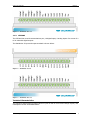
GTS2001
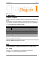
GTS2001 has a serial communications port, 16 digital inputs and 14 digital outputs.
The distribution of input and output terminals is shown below:
www.exemys.com
Rev. 2.3.0 – Dic 2011
5
GTS’ User’s Manual
Exemys
Figure 1 – Terminals 1 to 18
Figure 2 – Terminals 19 to 36
1.1.2
GTS3002
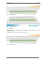
The GTS3002 has a serial communications port, 16 digital inputs, 6 analog inputs of 0 to 10 volts
and 6 digital outputs.
The distribution of input and output terminals is shown below:
Figure 3 – Terminals 1 to 18
www.exemys.com
Rev. 2.3.0 – Dic 2011
6
GTS’ User’s Manual
Exemys
Figure 4 – Terminals 19 to 36
1.1.3
GTS3003
The GTS3003 has a serial communications port, 16 digital inputs, 6 analog inputs of a current of 0
to 20 mA and 6 digital outputs.
The distribution of input and output terminals is shown below:
Figure 5 – Terminals 1 to 18
Figure 6 – Terminals 19 to 36
Technical Characteristics
The minimum and maximum possible values in inputs as well as current and voltage outputs, and
consumption of GTS are detailed below:
www.exemys.com
Rev. 2.3.0 – Dic 2011
7
GTS’ User’s Manual
Exemys
1.1.4 Power Supply
Parameter
Input voltage
Consumption idle
Consumption in
transmission
Condition
GTS
GTS
GTS
GTS
to
to
to
to
30
10
30
10
Vdc
Vdc
Vdc
Vdc
Minimum Maximum
10
30
40
100
300
800
Units
Vdc
mA
mA
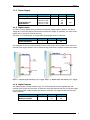
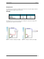
1.1.5 Digital inputs
In order to activate digital inputs an external continuous voltage must be applied. This power
supply has to share the GND terminal with the GTS power supply. If necessary, the same power
supply used to power the GTS can be used.
The input is of a sinking type. It accepts PNP sourcing type sensors or devices.
Parameter
Activated input
Input impedance
Minimum
3.5
2
Maximum
28
Units
Vdc
KΩ
Two examples of how to connect directly from the same power source of the GTS as well as an
external power supply where it can be seen that they must share a common terminal are shown.
Figure 7 - Digital input with single power supply Figure 8 - Digital input with double power supply
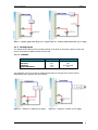
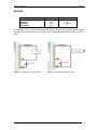
1.1.6 Digital Outputs
The digital outputs are open collector type. The connected load must be supplied with and
external power supply and they have to share the same GND terminal with the GTS power supply.
Use the same power supply to power the device if necessary. The output is NPN sourcing type
(Open Collector)
Parameter
Maximum voltage
Maximun current
www.exemys.com
Minimum
Maximum
45
50
Rev. 2.3.0 – Dic 2011
Units
Vdc
mA
8
GTS’ User’s Manual
Exemys
Figure 9 – Digital output with single power supply Figure 10 – Digital output with double power supply
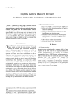
1.1.7 Analog Inputs
The analog inputs referenced to the GND terminal of the GTS, so the power supply to power the
sensor must share the GND terminal with the GTS.
1.1.7.1 GTS3002
Parameter
Value
10.00
0.01
±0.2
>10
Full scale
Precision
Tolerance
Input impedance
Units
Vdc
Vdc
% of full scale
KΩ
Two examples of how to connect a voltage analog input for a single power supply and for
independent power supplies are shown below.
Figure 11 – Analog for a single power supply
www.exemys.com
Figure 12 – Analog for a double power supply
Rev. 2.3.0 – Dic 2011
9
GTS’ User’s Manual
Exemys
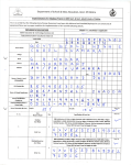
1.1.7.2 GTS3003
Parameter
Full scale
Precision
Tolerance
Shunt resistance
Value
20.00
0.01
±0.4
120
Units
mA
mA
% of full scale
Ω
Two examples where you can see the connection of a 4 – 20 mA sensor sharing the power supply
with the GTS for passive sensors or for an active sensors with independent power supply are
shown below.
Figure 13 – Analog Input for a passive sensor
www.exemys.com
Figure 14 – Analog Input for an active sensor
Rev. 2.3.0 – Dic 2011
10
GTS’ User’s Manual
2
Exemys
Installation
Power supply connection
Figure 15 – Power supply terminals
Serial connection
2.1.1 RS232 Connection
Figure 16 – RS232 cable pinout
www.exemys.com
Rev. 2.3.0 – Dic 2011
11
GTS’ User’s Manual
Exemys
2.1.2 RS485 and RS422 Connections
Figure 17 –RS485 and RS422 pinout
Installation of the SIM card
For the correct operation of the device the SIM card must meet the following requirements:
•
•
•
The installed card must have a subscription or contract providing the GSM services
Verify that the telephone number assigned to the SIM card is known.
If the PIN (security code) of the SIM card is activated you must know it and enter into the
GTS when requested.
Configuring the PIN of the SIM Card
If you place a SIM card with the PIN activated, the GTS will indicate the fault by a fast flashing of
the 3 LEDs in a synchronized manner. In this case the PIN must be entered through the GTS
Configurator Sotware. For more information see SIM card
If the entered PIN is not correct the device will not allow sending or receiving SMS. In case the
PIN is correct the GTS will store the entered code and the will continue with the normal operation.
Important: remember that if you enter 3 times the incorrect PIN number, the SIM card will block.
To unblock it you will have to enter the card’s PUK. For more information please contact
[email protected]
Once the PIN is entered, you will not need to enter it again unless you change the SIM card.
Important: When you place or remove the SIM card verify that the device is not energized;
otherwise the SIM card could be irreversibly damaged.
LED indicators
The GTS has 3 LED indicators: Power, SMS and Configuration
The Power LED indicates the device is energized.
www.exemys.com
Rev. 2.3.0 – Dic 2011
12
GTS’ User’s Manual
Exemys
The SMS LED indicates the device managed to access the SIM, that has an acceptable signal level
and that is ready to operate; this LED also indicates with a single flash the reception and sending
of an SMS.
The Configuration LED indicates when the device is being accessed through the serial port by
the GTS Configurator Software for its monitoring and configuration.
Figure 18 – LED in the front panel
Power LED
Fast flashing
SMS LED
Configuration LED
Description
The GTS is turning on the
internal modem
The GTS is subscribed to the
GSM network and is ready to
operate
Sending and receiving of SMS
Turns on ½ second
and turns off ½
second
Fast flashing in a
synchronized manner
with the other two
LEDs
Alternate flashing
with the SMS LED
GTS Configurator connected
Constantly on
A single flash
Fast flashing in a
synchronized
manner with the
other two LEDs
Alternate flashing
with the SMS LED
www.exemys.com
Fast flashing in a
synchronized
manner with the
other two LEDs
Alternate flashing
with the Power
and Configuration
LEDs
Rev. 2.3.0 – Dic 2011
The GTS could not detect the
presence of the SIM card or
the corresponding PIN is not
configured.
The level of the detected
signal is not sufficient for a
correct operation. Verify if
the antenna is correctly
placed.
13
GTS’ User’s Manual
3
Exemys
GTS Configurator Software
Installation and Utilization
The GTS Configurator is the software provided with the product used to configure the GTS.
This application was developed with the easy-to-use philosophy and allows the configuration and
monitoring of the GTS device. The GTS Configurator can be installed on the following platforms:
Windows 98 SE/ME, Windows 2000/NT4, Windows XP and Windows Vista.
3.1.1
Installation
To install the GTS Configurator follow these steps:
•
•
•
•
To begin the installation of the program insert the GTS CD and execute setup.exe.
A welcome screen will appear in the monitor, follow the installation instruction that will
request the necessary information to complete the installation. Click on “Next” to
continue.
Destination folder: Select the folder where the application program will be installed.
Wait for the installation program to finish copying all the necessary files to your hard disk,
and press “Finish” to end the installation process.
Once installed, you will be able to see in its menu, Programs a folder called Exemys, which
contains the links to software provided by the company. In this folder you will find another folder
called GTS Configurator, this contains the links GTS Configurator and Uninstall GTS
Configurator.
3.1.2
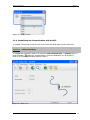
General Description
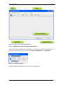
The following figure shows the GTS Configurator main screen, with its different sections.
It has a menu, a tool bar which is a quick access to the menu and in the lower part a status bar
presenting contextual help, the connection status of the GTS configurator and the selected COM
port.
www.exemys.com
Rev. 2.3.0 – Dic 2011
14
GTS’ User’s Manual
Exemys
Figure 19 – Main screen of the GTS Configurator
3.1.3
Configuration of the connection with the GTS
Before being able to establish the communication, it is necessary to configure the program so it
uses the correct serial port. Select in the menu GTS’ Communications -> Serial Port
Figure 20 – COM Configuration
And then indicate the serial port where the GTS will be connected.
www.exemys.com
Rev. 2.3.0 – Dic 2011
15
GTS’ User’s Manual
Exemys
Figure 21 – COM selection
3.1.4 Establishing the Communication with the GTS
To establish communication with the GTS, first connect the serial cable with the RS232 port.
It is necessary for the cable to have the connection for the flow control pins (see
Installation – serial connection).
To establish the connection select in the menu the GTS communication -> Connect option or
press the button.
When the communication is correctly established, you will be able to
observe on the screen information about the device.
Figure 22 – Main screen
www.exemys.com
Rev. 2.3.0 – Dic 2011
16
GTS’ User’s Manual
Exemys
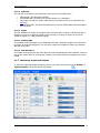
3.1.5 Organization
The GTS Configurator is divided into two main fundamental components, on one side we find the
monitoring tools that will let you visualize the GTS operation and status. On the other side we
have the configuration tools that permit to select and determine the device operation.
Figure 23 – Organization of the GTS Configurator
If the GTS Configurator finds an unknown model it will not enable the configuration
and monitoring buttons. In this case contact [email protected] to obtain the updated
software version.
Monitoring
3.1.6
SMS Monitoring
To enter the SMS Monitoring screen you must access the menu with the following path Monitor > SMS or by pressing the SMS monitor button
Figure 24 – SMS monitor screen
www.exemys.com
Rev. 2.3.0 – Dic 2011
17
GTS’ User’s Manual
Exemys
3.1.6.1 SIM Card
The GTS tell us the status of the SIM card, it can contain four possible states.
•
•
•
•
SIM Card OK: The SIM works perfectly
Inaccessible SIM: The SIM is not correctly placed or it is damaged.
Enter PIN: The SIM has a PIN number that must be entered. For more information see
SIM Card
Blocked SIM (PUK): The SIM is blocked by PUK, enter the PUK number placing the SIM in
the cell phone.
3.1.6.2 Signal
The GTS indicates the quality of the signal at this moment, and it is shown in dB and the device
will have to count on a minimum signal to work correctly. The range of values can vary from 113dB (no signal) to -51dB (maximum signal).
3.1.6.3 Sending SMS
It is possible to send messages to any destination and with a maximum length of 100 characters
by means of the GTS Configurator. You only have to place the telephone number, the message
and then press Send.
3.1.6.4 SMS Reception
In the SMS monitoring screen the GTS reports all received messages and the telephone number of
the sender. Please take into account that if switch screens while receiving messages, they will be
erased.
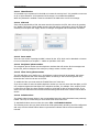
3.1.7 Monitoring Inputs and Outputs
To enter the Input and Outputs monitoring screen you have to access the menu of Monitor ->
Inputs/Outputs or press the Monitor IO’s button.
Figure 25 – Inputs and Outputs monitoring screen
www.exemys.com
Rev. 2.3.0 – Dic 2011
18
GTS’ User’s Manual
Exemys
3.1.7.1 Digital Inputs
The GTS informs in real time the value of the digital inputs. Take into consideration that the
number of inputs can differ according to the GTS model.
3.1.7.2 Digital Outputs
The GTS informs in real time the value of the digital outputs. It’s also possible to act on them.
Take into consideration that the number of outputs can vary according to the GTS model.
3.1.7.3 Analog inputs
The GTS continuously informs the value of analog inputs. Take into consideration that some
models do not have analog inputs and according to the model they can be voltage inputs or
current inputs.
Configuration
3.1.8 Basic Configuration
To enter the basic Configuration screen you must access the menu in Configuration -> Basic or
by pressing the basic configuration button.
Figure 26 – Basic configuration screen
Every time a change is made in the configuration you must press the “Apply” button to
transfer it to the GTS.
The changes are permanently stored when the communication ends with the GTS
Configurator. If a power outage takes place before this happens, the changes made
will be lost.
www.exemys.com
Rev. 2.3.0 – Dic 2011
19
GTS’ User’s Manual
Exemys
3.1.8.1 Identification
It is possible to put a password in the SMS to increase the security level. It is possible to enter text
of up to eight characters. If the password is left empty it is considered as disabled.
When the password is enabled it must be included in the SMS at the end of the message.
3.1.8.2 SIM card
If the SIM is protected by a PIN, the same must be informed to the GTS, this is done by pressing
the “Modify PIN” button which enables entering the PIN and its confirmation. Once both fields are
entered you must press the “Apply” button so changes are applied and the SIM card is enabled.
Figure 27 – Entering the PIN
3.1.8.3 Parse mode
There are two modes of parsing the SMS’ received by the GTS, which can be Standard or Custom.
For more information see chapter 5 – Modes of operation of the GTS.
3.1.8.4 Recipients’ phone number
The recipients’ phone number are the telephone numbers that will receive all the messages sent
by the GTS, either messages of the serial port, change events or alarm reports.
3.1.8.5 Filter List by phone number
The GTS will allow you to define up to 15 telephone numbers that will be accepted, this means
that those telephones that send messages and do not belong to this list will be ignored. Only
those that are in the list can act on the GTS.
To enable the filter you must mark the “Enable Filter List” check box.
If you do not want to enter the whole telephone number you can only enter the last digits, so GTS
only compares against the last digits of the telephone number, for example: if the number 12345
is entered in the filter list, those numbers ending in 12345 will be able to access the GTS. If you
want to be less restrictive enter 345 and all those ending with these three numbers will be able to
access.
3.1.8.6 Default values
The Default Values button places in the corresponding boxes the values that have been previously
loaded. This way we avoid having to enter these three values each time.
To load default values we must enter the menu File -> Edit Default Values.
The following screen lets you place values that will be permanently stored by the GTS Configurator
and every time the Default Values button is pressed the indicated values will be automatically
inserted.
www.exemys.com
Rev. 2.3.0 – Dic 2011
20
GTS’ User’s Manual
Exemys
Figure 28 – Default values edit screen
3.1.9 Serial Port Configuration
To enter the serial port configuration screen you must access from the menu to Configuration > Serial Port or by pressing the Serial Port Configuration button of the GTS
Figure 29 – Serial Port configuration screen
3.1.9.1 Serial Port
The GTS has a serial communications port that has different configurations, among them we find
Baud Rate, Data Bits, Parity and flow control.
www.exemys.com
Rev. 2.3.0 – Dic 2011
21
GTS’ User’s Manual
Exemys
3.1.9.2 Packing
The GTS will attempt to gather several data before sending a packet through the network; this
way it takes maximum advantage of each message and the communication costs are reduced. The
criteria implemented for the end of the packet are the following:
•
•
Time window (0…1000ms): once data are received, the GTS will await in silence this time
before sending the SMS. To disable this criterion the time window must be configured in 0
ms.
End character (0…255): Indicates the last character of a serial stream before sending the
SMS.
Important: if the end character criterion is enabled and the time window is disabled the GTS will
store the received data for an indefinite time until it receives the configured character or until GTS’
storage capacity reaches its limit.
If both criteria are used the first condition to be fulfilled will cause the sending of the SMS.
3.1.9.3 Serial Port mode
There are two modes for the Serial Port: Transparent and By Commands, for more information see
in chapter 5 – Operational modes of the Serial port -.You must take into account that in the By
command mode, the end character and the Window Time make no sense and are disabled.
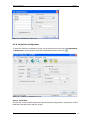
3.1.10 Configuration of Inputs and Outputs
To enter the Configuration screen for Inputs and Outputs you can access from the menu through
Configuration -> Inputs/Outputs or by pressing the IOs’ Configuration button.
In the configuration screen of Input and Outputs you can find two or three tabs corresponding to
“Digital inputs”, “Digital outputs” and “Analog inputs” as you can see in the following figure.
Figure 30 – Configuration tabs of IOs
Take into consideration that not all GTS models have Analog Inputs. In this case, the Analog
Inputs tab will not be visualized.
There are two different configurations for Inputs and Outputs. One configuration in Standard
Mode and the other one in Custom mode.
www.exemys.com
Rev. 2.3.0 – Dic 2011
22
GTS’ User’s Manual
Exemys
3.1.10.1 Configuration of Inputs and Outputs in standard mode
3.1.10.1.1
Digital Inputs
Figure 31 – Configurations of digital inputs in standard mode
In the table of digital inputs three fields are shown:
Input: Indicates the Input number and is not editable.
Name: Name assigned to the corresponding input. Is the name that will be visualized when a
change in the input is reported.
Enable: Allows enabling the input that we want to use to avoid false triggers.
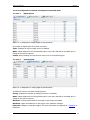
3.1.10.1.2
Analog Inputs
Figure 32 – Configuration of analog inputs in standard mode
Six fields are shown in the table of Analog Inputs:
Analog: Indicates the number of analog input and is not editable.
Name: Name assigned to the corresponding input. Is the name that will be visualized when a
change in the input is reported.
Minimum: Lower threshold limit for the trigger of the minimum message.
Maximum: Upper threshold limit for the trigger of the maximum message.
Hysteresis: Margin to avoid false triggers. For more information see Appendix D – Operation of
Hysteresis -
www.exemys.com
Rev. 2.3.0 – Dic 2011
23
GTS’ User’s Manual
Exemys
Enable: Allows enabling the input that we want to use to avoid false triggers.
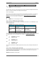
3.1.10.1.3
Digital Outputs
Figure 33 – Configuration of the digital outputs in standard mode
Three fields are shown in the table of digital outputs:
Outputs: Indicates the number of the output and is not editable.
Name: Name assigned to the corresponding output. Is the name to which reference can be made
to control the status of such output.
Follow analog alarm: Allows activation of the output so it can follow the status of analog inputs
of another GTS. For more information see chapter 6 – Practical Applications -.
3.1.10.2 Configuration of Inputs and Outputs in custom Mode
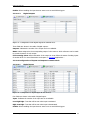
3.1.10.2.1
Digital Inputs
Figure 34 – Configuration of digital inputs in custom mode
Four fields are shown in the table of digital inputs:
Input: Indicates the number of the input and is not editable.
Low-High Edge: Text that will be sent when input is activated.
High-Low Edge: Text that will be sent when input is deactivated.
Enable: Allows enabling the input that we want to use to avoid false triggers.
www.exemys.com
Rev. 2.3.0 – Dic 2011
24
GTS’ User’s Manual
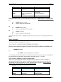
3.1.10.2.2
Exemys
Analog inputs
Figure 35 – Configuration of analog inputs in custom mode
Eight fields are shown in the table of Analog Inputs:
Analog: Indicates the number of the analog input and is not modifiable.
Minimum: Lower threshold limit for the triggering of the minimum message.
Maximum: Upper threshold limit for the triggering of the maximum message.
Hysteresis: margin to avoid false triggers.
Minimum message: Message that will be sent when the analog input changes from a normal
state to minimum state.
Normal message: Message that will be sent when the analog input changes from a state of
minimum or maximum to a normal state.
Maximum message: Message that will be sent when the analog input changes from a normal
state to a maximum state.
Enable: Allows enabling the input that we want to use to avoid false triggers.
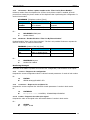
3.1.10.2.3
Digital Outputs
Figure 36 – Configuration of digital outputs in custom mode
Three fields are shown in the table of digital outputs:
Output: Indicates the number of digital outputs and is not editable.
Activate: Message configured to activate the corresponding output.
Deactivate: Message configured to deactivate the corresponding output.
Activate Response: Message returned once the activation action is executed.
Deactivate Response: Message returned once the deactivation action is executed.
www.exemys.com
Rev. 2.3.0 – Dic 2011
25
GTS’ User’s Manual
Exemys
4 Configuration, Monitoring and Control by SMS
All special messages that the GTS can receive are shown in this chapter, through them it is
possible to know the configuration, modify it, and also know the status of the inputs and outputs
or act on them.
Take into consideration that between every parameter being sent there must be only
one space. The messages send a confirmation that have been received and also if an
error occurred in the format.
Some of the messages only work in the standard operation mode and not in the custom mode,
this is indicated in each one.
4.1 Configuration Messages
BY means of SMS, it is possible to configure some of the characteristics of the GTS. In the current
chapter the messages and the required format for each one of the configuration messages is
described.
4.1.1
CSERIAL – Serial port configuration
Configures the parameters of the serial port. It works in both modes.
CSERIAL {Baudrate} {Data bits} {Parity} {Flow Control} [Pass]
Parameter
Baud rate
Data bits
Parity
Flow control
Pass
Description
Speed of serial
communication:
Number of data bits
Parity error detection
Enables or not the data
flow control
Password (optional)
Values
1200, 2400, 4800, 9600, 19200,
57600, 115200
7, 8
E (Even), O (Odd), N (No parity)
E (Enable), D (Disable)
Configured password
Ex.:
→
←
4.1.2
CSERIAL 9600 8 N E pass
Port configured
ADDRECIP – Adds an SMS recipient
Adds a phone number where the SMS’ will be sent. It works in both modes.
ADDRECIP {phone number} [Pass]
Parameters
Description
Phone number Phone number that will be
www.exemys.com
Values
From 0 to 15 numeric characters
Rev. 2.3.0 – Dic 2011
26
GTS’ User’s Manual
Exemys
added
Password (optional)
Pass
Configured password
Ex.:
→
←
4.1.3
ADDRECIP 1165845968 pass
Recipient added
DELRECIP – Deletes an SMS recipient
Deletes a phone number where the SMS’ will be sent. It works in both modes.
DELRECIP {phone number} [Pass]
Parameters
Description
Phone number Phone number that will be
deleted
Pass
Password (optional)
Values
From 0 to 15 numeric characters
Configured password
Ex.:
→
←
4.1.4
DELRECIP 1165845968 pass
Recipient deleted
CPASS – Password configuration
Configures the password that will be required for some messages. It works in both modes.
CPASS {New password} [Pass]
Parameters
Description
New password New password to be
entered
Pass
Password (optional)
Values
From 0 to 8 numeric characters
Configured password
Ex.:
→
←
CPASS newpass pass
Password configured
If you want to erase the password you have leave two spaces between CPASS and the configured
password.
4.1.5
ADDSENDER – Adds a phone number to the “Filter List By Phone Number”
Adds another phone number to the list of authorized telephone numbers. Remember that only 15
numbers are allowed. It works in both modes.
ADDSENDER {Telephone number} [Pass]
Parameters
Telephone
number
Pass
Description
Telephone number to be
added to the list
Password (optional)
Values
From 1 to 10 numeric
characters
Configured password
Ex.:
→
←
www.exemys.com
ADDSENDER 25485 pass
Sender Added
Rev. 2.3.0 – Dic 2011
27
GTS’ User’s Manual
4.1.6
Exemys
DELSENDER – Deletes a phone number to the “Filter List By Phone Number”
Deletes a number from the telephone list. If Filter List by Phone number is enabled, GTS will
prevent from erasing the phone number of the telephone that is performing this configuration. It
works in both modes.
DELSENDER {Telephone number} [Pass]
Parameters
Telephone
number
Pass
Description
Telephone number that
will be deleted
Password (optional)
Values
From 1 to 10 numeric
characters
Configured password
Ex.:
→
←
4.1.7
DELSENDER 25485 pass
Sender deleted
ENSENDER – Enables/Disables “Filter List By Phone Number”
Enables/Disables “Filter List By Phone Number”. The list is only enabled if whoever requests the
action is on the list. It works in both modes.
ENSENDER {Status of the list} [Pass]
Parameters
Status of the
list
Pass
Description
Indicates if one wants to
enable or disable the list
Password (optional)
Values
ON, OFF
Places password
Ex.:
→
←
ENSENDER ON pass
Senders list enabled
Monitoring Messages
By means of the SMS it is possible to know the GTS’ configuration, and the status of the inputs.
4.1.8
LISTALL – Requests the configuration
Requests the current configuration values. It doesn’t contain parameters. It works in both modes.
Ex.
→
←
4.1.9
LISTALL
SERIAL 9600,8,N,E MODE: STD
LISTRECIP – Requests the recipients list
Requests the current recipients list. It doesn’t contain parameters. It works in both modes.
Ex.
→
←
LISTRECIP
Recipients list: 112053521, 15248454548,1254454542
4.1.10 SIGNAL – Requests the value of the signal
Requests the value of the signal in the GTS at that instant. It works in both modes.
Ex.:
→
←
www.exemys.com
SIGNAL
Signal: -96 dB
Rev. 2.3.0 – Dic 2011
28
GTS’ User’s Manual
Exemys
4.1.11 LISTSENDER – Requests the list of authorized telephones
Requests the list of authorized telephones that can access the GTS, the character in parenthesis
indicates whether it is enabled (E) or disabled (D). It works in both modes.
Ex.:
→
←
LISTSENDER
Senders(E): 54854,1548548548,1236
4.1.12 DINPUTS – Requests the value of digital inputs
Requests the value of digital inputs at that instant, this message can originate as a response one
or two messages depending on the number of inputs that the model is using. It works in both
modes.
Ex.:
→
←
DINPUTS
IN1=ON IN2=ON IN3=OFF IN4=ON (Continues until it sends all the inputs)
4.1.13 DOUTPUTS – Requests the value of the digital outputs
Requests the value of the digital outputs at that instant, this message can originate as a response
one or two messages depending on the number of outputs the model is using. It works in both
modes.
Ex.:
→
←
outputs)
DOUTPUTS
OUT1=OFF OUT2=ON OUT3=OFF OUT4=OFF (Continues until it sends all the
4.1.14 AINPUTS – Requests the value of analog inputs
Requests the value of analog inputs at that instant, this message can originate as a response one
or two messages depending on the number of analog inputs of the model being used. It works in
both modes.
Ex.:
→
←
AINPUTS
AIN1=5.90v AIN2=6.02v AIN3=0.23v (Continues until is sends all the inputs)
4.1.15 VERSION – Requests the hardware and firmware versions of the device
Through this command it is possible to know the hardware and firmware versions of your device.
Ex.:
→
←
VERSION
GTS3002 - HARDWARE: V3.0 FIRMWARE: V1.1.0
Control Messages
By means of SMS it is possible to act on the GTS
4.1.16 SERIAL – Sends messages through the serial port
When you want to send data through the serial port you use this command that precedes the
message that we will send. It only works in Standard mode.
SERIAL {Message} [Pass]
Parameter
Message
www.exemys.com
Description
Message we want to send
through the serial port
Values
From 1 to 120 characters
Rev. 2.3.0 – Dic 2011
29
GTS’ User’s Manual
Password (optional)
Pass
Ex.:
→
Exemys
Configured password
SERIAL This is a test message pass
The word “pass” will not go out the serial port if we have the password configured with this text,
that is, as a result we will have in the output of the serial port:
This is a test message
If we want to send through the serial port data not having ASCII representation, for example an
ENTER (0x0D) at the end of the message, we must send the decimal code of the character
between <>. For more information see Appendix C – Table of characters and the decimal
equivalents -.
Ex.:
→
SERIAL This is a test message<13> pass
4.1.17 DOUTPUT – Modifies the status of outputs
Changes the status of any of the outputs, it is possible to turn them on or off individually. It only
works in Standard mode.
DOUTPUT {Name (Number)} {Status} [Pass]
Parameter
Name
Number
Status
Pass
Description
Values
Name assigned in the GTS From 1 to 10 characters
Configurator
Output number
From 1 to n (Number of outputs
for the model)
Status in which we want
ON or 1 to turn on
to place the output
OFF or 0 to turn off
Password (optional)
Configured password
It is possible to act on the output by placing only the name or number, if both are placed it acts by
the output number. For more information see in chapter 3 – Standard Digital Outputs.Ex1.:
→
←
DOUTPUT Motor(3) ON
DOUTPUT 3 ON
→
←
DOUTPUT Motor 1
DOUTPUT Motor 1
→
←
DOUTPUT (3) OFF
DOUTPUT 3 OFF
Ex2.:
Ex3.:
If you give the same name to multiple outputs and you act by name, all outputs will perform the
action.
4.1.18 PULSE – Generates a pulse at the output
Generates a pulse of a determined duration in the message. The generated pulses are first turning
on and then turning off, if the output is on, it will turn off once the duration of the pulse has
ended. It only works in Standard mode.
PULSE {Name(Number)} {Time} [Pass]
www.exemys.com
Rev. 2.3.0 – Dic 2011
30
GTS’ User’s Manual
Exemys
Parameter
Name
Number
Time
Pass
Description
Values
Name assigned in the GTS From 1 to 10 characters
Configurator
Output number
From 1 to n (Number of output
for its model)
Duration of the pulse in
From 1 to 60 seconds
seconds
Password (optional)
Configured password
It is possible to act on the output placing only the name or the number, if both are placed it will
act by the output number. For more information see chapter 3 –Digital Outputs In Standard ModeEx1.
→
←
PULSE Reset(4) 10 pass
Pulse in output 4 of 10 seconds
→
←
PULSE Reset 10 pass
Pulse in output Reset of 10 seconds
→
←
PULSE 4 10 pass
Pulse in output 4 of 10 seconds
Ex2.
Ex3.
If you place the same name to multiple outputs, and it acts by name; all outputs will perform the
action.
Report Messages
These messages are generated asynchronically by the GTS to report certain events and will be
sent to the configured receipt phone numbers.
4.1.19 SERIAL – Sends messages entering by the serial port
When data enter through the serial port and a packet is formed according to the packing criteria,
it is sent to the configured receipt phone numbers. This message is only sent in Standard mode.
SERIAL {Message}
Ex.:
← SERIAL Test message from the serial port
You should take into account that those characters entering the serial port that are not ASCII will
be transformed to its equivalent representation in decimals with the <> format.
4.1.20 AINPUT – Reports the status of analog alarms
When any of the analog inputs enters in an alarm status or leaves the status a message is
generated informing about the situation. Maximum, minimum limits, hysteresis and name are
configured by the GTS Configurator, for more information see in chapter 3 –Analog Inputs in
stander mode-. This message is only sent in Standard mode.
AINPUT {Name(Number)} {Status}
Parameter
Name
Number
Status
www.exemys.com
Description
Values
Name assigned in the GTS From 0 to 10 characters
Configurator
Input number
From 1 to n (Number of inputs
for its mod el)
Alarm status
MAXIMUM ALARM
Rev. 2.3.0 – Dic 2011
31
GTS’ User’s Manual
Exemys
MINIMUM ALARM
ALARM NORMALIZED
Ex.:
←
AINPUT Tank(2) MAXIMUM ALARM
4.1.21 DINPUT – Reports the change of digital inputs
When any of the digital inputs modifies its status a change report is generated automatically that
will be sent to the configured recipient phone numbers. Each one of the inputs can be enabled
independently, for more details see in chapter 3 –Digital Inputs in standards mode-. This message
is only sent in Standard mode.
DINPUT {Name(Number)} {Status}
Parameter
Name
Number
Status
Description
Values
Name assigned in the GTS From 0 to 10 characters
Configurator
Input number
From 1 to n (Number of inputs
for its model)
Input status
ON, OFF
Ex.:
←
INPUT Sensor(5) ON
Customized Messages
Those messages that are only sent in Standard mode have their equivalent in custom mode. Here
is the detail of how the messages operate in this mode.
4.1.22 Messages to or from the Serial Port
To send messages to the serial port in Standard mode you use the SERIAL command, in custom
mode this does not work. Simply, the work methodology is that all messages arriving at the GTS
will be sent to the serial port, except those messages that are reserved or that correspond to the
activation or deactivation of outputs.
Similarly, if you send a message through the serial port, it automatically becomes an SMS and is
sent to the configured receipt phone list. In this case, SERIAL will not be the prefix of the message
text, therefore the message is sent as it is to its destination.
Remember that if characters not corresponding to the ASCII standard are received or want to be
sent through the serial port, these are represented by their decimal equivalent between <>.
If you are working with the serial port in By Commands mode, the operation is similar except that
the port has a specific format stream. For more information see chapter 5 – Operational modes of
the serial port-.
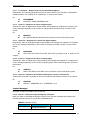
4.1.23 Handling of digital outputs
First, the messages to “activate” and “deactivate” the outputs must be configured by the GTS
Configurator.
For this you must access the configuration of customized outputs and place the desired message
to perform the action.
www.exemys.com
Rev. 2.3.0 – Dic 2011
32
GTS’ User’s Manual
Exemys
Figure 37 – Configuration of output activation and deactivation messages
Once the messages are configured you only need to send the entered text to perform the desired
action.
Ex.:
If we want to activate output 4 we send:
→
←
Turn output 4 on
Output 4 turned on
It is possible to repeat the same message to perform simultaneously multiple actions to activate
and also deactivate outputs.
Take into consideration that if you place reserved names to turn on outputs like for example:
DINPUTS, DOUTPUTS the name of the used function will have no effect. Avoid using reserved
words in customized messages.
4.1.24 Report of Digital Inputs
When the status of one of the digital inputs is modified, an SMS is generated automatically
informing about the event. In the case of a customized messages we can define the text that will
be sent when the event occurs, either when the input produces a transition from 0 to 1 or vice
versa.
The message is determined by means of the GTS Configurator in the configuration screen of
Digital Inputs in custom mode.
www.exemys.com
Rev. 2.3.0 – Dic 2011
33
GTS’ User’s Manual
Exemys
Figure 38 – Configuration of messages of events of digital inputs
Ex.:
Event: Transition from 0 to 1 of input 3
← Input 3 off-on edge
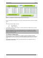
4.1.25 Report of analog inputs
When the analog inputs change value and status is changed according to the configured maximum
and minimum, a message is generated automatically reporting the change. The generated
message can be configured by means of the GTS Configurator in the configuration of Analog
Inputs in custom mode.
Figure 39 – Configuration of messages of analog input events
If for example we have an upper limit above 9.0V and the input exceeds that threshold the
corresponding message is triggered automatically and sent to the configured recipients.
Ex.:
Event: Analog input 4 changes from 8.9V to 9.1V
←
AI4 over maximum
Special attention must be paid to the configured value of hysteresis to avoid the system to send
SMS continuously when the input is oscillating in the change threshold. For more information see
Appendix D – Hysteresis operation.
www.exemys.com
Rev. 2.3.0 – Dic 2011
34
GTS’ User’s Manual
Exemys
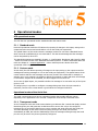
5 Operational modes
GTS operational modes
The GTS has two operational modes: standard mode and custom mode.
5.1.1 Standard mode
Under this operational mode the GTS allows the reporting of changes in the inputs, acting on the
outputs and also receives and sends SMS to or from the serial port respectively.
The special feature of this mode is that the messages received or sent have a Standard format
which cannot be modified and you are restricted to. This has the advantage that the messages
can be interpreted by other GTS.
The Standard messages are detailed in chapter 4 – Configuration, Monitoring and Control by SMS
– where the format of each of the Standard commands is shown. To better understand about this
mode see chapter 6 – Practical Application – where useful layouts are shown where this
operational mode is applied.
5.1.2 Custom mode
In this mode, the GTS allows reporting of changes in the input, acting on the outputs as well as
sending and receiving messages to or from the serial port respectively. The special feature of the
custom mode is that the sent messages can have any format. This means that for example, to
activate one or more outputs it is possible to define the message we want and when the message
is received the outputs will be activated, the same happens to turn them off.
In the case of digital inputs, it is possible to define the message to be sent when any of the inputs
goes on or off.
In analog inputs, it is possible to configure a message being sent when the input exceeds a
maximum, returns to the normal status or goes bellow the configured minimum.
Operational modes of the Serial Port
The serial communication port has two operational modes that provide different options
depending on the application to be resolved: Transparent mode and By Commands mode.
5.1.3 Transparent mode
In the Transparent mode the serial communications port behaves like a tunnel that simply receives
data through the port and generates an SMS that will be sent to the only to the configured
recipients list. Or receives an SMS from any source number and sends it through the serial port.
The main advantage of this mode is that everything arriving to the serial port becomes
automatically an SMS, but with the disadvantage is that the message entering through the serial
port can only be sent to the phones previously configured.
www.exemys.com
Rev. 2.3.0 – Dic 2011
35
GTS’ User’s Manual
Exemys
Remember that if the GTS is configured en standard mode the word SERIAL will be appended to
the messages received on the serial port. Also remember that will have to start your SMS’ with the
word SERIAL when you wont to send messages to the serial port.
In the Transparent mode of the serial port only ASCII characters are sent, those characters
without valid ASCII representation are sent between <>.
5.1.4 By commands mode
In this mode, the serial port must receive a data stream with a defined command to send a
message.
Among other things, this mode can be used to send a message to any destination and not only to
the configured recipients list. When a message is received it is also possible to know the source
number of the message and the time stamp when the message was sent. For more details see
Appendix B – Format of the stream in By commands mode -.
www.exemys.com
Rev. 2.3.0 – Dic 2011
36
GTS’ User’s Manual
Exemys
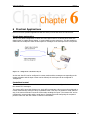
6 Practical Applications
Here we list some practical applications that can show you how and where to use the GTS.
Simple home automation
This is a very basic configuration in which the GTS report events to a cellular phone when the
digital inputs or analog alarms change, or receive data from the serial port. It’s also possible to
send orders to modify the status of the outputs or messages to the serial port from a cell phone.
Figure 40 – Simple home automation layout
In this case the GTS can be configured in custom mode and the messages corresponding to the
output activation and the input events can be defined, the serial port can be configured in
Transparent.
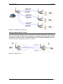
Centralized control
This is a layout where there is a data concentrator connected to an intelligent device that receives
the remote GTS’ messages.
The remote GTS’ report the changes to a single GTS concentrator, this one must be configured in
custom mode and the serial port in By Commands mode. This way it is possible to send orders to
any of the remote GTSs and know the GTS number sending the report. The remote GTS’ can be
configured in custom mode and the serial port in Transparent mode configuring the recipient’s
phone of each one with the number of the GTS concentrator.
www.exemys.com
Rev. 2.3.0 – Dic 2011
37
GTS’ User’s Manual
Exemys
Figure 41 – Centralized control layout
Inputs/Outputs+Serial Tunnel
This configuration works as a tunnel between the GTS’. Serial port data entering through one end
goes out on the other end and vice versa. The inputs of a GTS are reflected in the other’s outputs.
It can choose to reflect the status of the analog inputs or the status of the digital inputs. The main
configuration to perform a tunnel is that both devices must be configured in Standard mode and
each one must have configured the other one’s number.
Figure 42 – Tunnel layout
www.exemys.com
Rev. 2.3.0 – Dic 2011
38
GTS’ User’s Manual
A
Exemys
Troubleshooting quick guide
1. I cannot connect with the GTS Configurator
1.1. I press the connect button and it gives me an error instantaneously
1.1.1. Verify that the selected serial port exists.
1.1.2. Verify that the port is not being used by another application.
1.1.3. If you use USB adapters to the serial port be sure that it is correctly connected
and configured.
1.2. I press the connect button and attempts to connect but it cannot do it
1.2.1. Verify that the connection cable of the serial port to the GTS is a complete cable
as the one indicated in the installation section.
1.2.2. Verify that the selected port is the adequate one.
2. The GTS does not respond to SMS messages
2.1. If the GTS Configurator shows the antenna crossed out
(LEDs flicker slowly
and in alternate manner).
2.1.1. The GTS has no signal. Verify:
2.1.1.1.
That the antenna is correctly connected.
2.1.1.2.
That you are within your cell phone operator coverage area.
2.2. The status of the SIM card indicates fault (LEDs flicker fast and in a
synchronized manner).
2.2.1. The GTS cannot access the SIM.
2.2.1.1.
If the GTS Configurator indicates “SIM Inaccessible”. Verify that the GTS
has a SIM card in place.
2.2.1.2.
If the GTS Configurator indicates “Enter PIN”: the SIM card has the PIN
Security code) activated, configure the correct PIN in the GTS (See Configuring
the PIN of the SIM card).
2.2.1.3.
If the GTS Configurator indicates “SIM blocked (PUK)”: the SIM card is
blocked by PUK.
2.3. No evidence of error.
2.3.1. Verify if the SIM card placed in the GTS has credit.
2.3.2. Verify if the SIM card has a subscription or account that lets you send SMS
messages.
2.3.3. Corroborate that the destination telephone number coincides with the number of
the SIM card of the GTS.
2.3.4. Ensure that the sent message is one supported by the GTS. If the message begins
with a word that the GTS cannot interpret it will not respond.
For more information on troubleshooting please contact [email protected]
www.exemys.com
Rev. 2.3.0 – Dic 2011
39
GTS’ User’s Manual
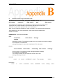
B
Exemys
Stream format in By Commands mode
All characters are in ASCII format, except those indicated between <>.
STX <0x02>
Command
SYN <0x16>
Data
ETX <0x03>
STX: Indicates the beginning of the transmission of the stream and is hexadecimal 2.
Command: It is a number formed by two characters and can go from 00 to 99.
SYN: This is a parameter separator and is a 16 hexadecimal.
Data: These are data corresponding to each command, it can contain multiple parameters.
ETX: Indicates the end of the transmission of the stream and is hexadecimal 3.
Available command:
Command ‘12’ – Send and receive SMS
Send:
Destination
number
SYN <0x16>
Message
Destination number: The telephone number to whom you want to send the message
SYN: separator 16 hexadecimal
Message: Message to be sent with a maximum of 120 characters
Receive:
Source number
SYN <0x16>
Time Stamp
SYN <0x16>
Message
Source number: The telephone number that generated the message
SYN: separator 16 hexadecimal
Time Stamp: Number that represents the seconds since 1970
Message: Message received
Ex. Send:
<0x02>
12
<0x16>
1152454545
<0x16>
Test message
<0x03>
Ex. Receive:
<0x02>
www.exemys.com
12
<0x16>
1152454545
<0x16>
Rev. 2.3.0 – Dic 2011
1524866981
<0x16>
Message
<0x03>
40
GTS’ User’s Manual
C
Exemys
Character table and decimal equivalent
0
1
2
3
4
5
6
7
8
9
10
11
12
13
14
15
16
17
18
19
20
21
22
23
24
25
26
27
28
29
30
31
32
33
34
35
36
37
38
39
40
41
42
43
44
45
46
47
48
49
50
51
52
53
54
55
56
57
58
59
60
61
62
63
www.exemys.com
NULL
SOH
STX
ETX
EOT
ENQ
ACK
BEL
BS
TAB
LF
VT
FF
CR
SO
SI
DEL
DC1
DC2
DC3
DC4
NAK
SYN
ETB
CAN
EM
SUB
ESC
FS
GS
RS
US
(space)
!
“
#
$
%
&
‘
(
)
*
+
,
.
/
0
1
2
3
4
5
6
7
8
9
:
;
<
=
>
?
64
65
66
67
68
69
70
71
72
73
74
75
76
77
78
79
80
81
82
83
84
85
86
87
88
89
90
91
92
93
94
95
96
97
98
99
100
101
102
103
104
105
106
107
108
109
110
111
112
113
114
115
116
117
118
119
120
121
122
123
124
125
126
127
@
A
B
C
D
E
F
G
H
I
J
K
L
M
N
O
P
Q
R
S
T
U
V
W
X
Y
Z
[
\
]
^
_
‘
a
b
c
d
e
f
g
h
i
j
k
l
m
n
o
p
q
r
s
t
u
v
w
x
y
z
{
|
}
~
128
129
130
131
132
133
134
135
136
137
138
139
140
141
142
143
144
145
146
147
148
149
150
151
152
153
154
155
156
157
158
159
160
161
162
163
164
165
166
167
168
169
170
171
172
173
174
175
176
177
178
179
180
181
182
183
184
185
186
187
188
189
190
191
Rev. 2.3.0 – Dic 2011
€
‘
ƒ
„
…
†
‡
ˆ
‰
Š
‹
Œ
Ž
‘
’
“
”
•
–
—
˜
™
š
›
œ
ž
Ÿ
¡
¢
£
¤
¥
¦
§
¨
©
ª
«
¬
®
‾
°
±
²
³
´
µ
¶
¸
¹
º
»
¼
½
¾
¿
192
193
194
195
196
197
198
199
200
201
202
203
204
205
206
207
208
209
210
211
212
213
214
215
216
217
218
219
220
221
222
223
224
225
226
227
228
229
230
231
232
233
234
235
236
237
238
239
240
241
242
243
244
245
246
247
248
249
250
251
252
253
254
255
À
Á
Â
Ã
Ä
Å
Æ
Ç
È
É
Ê
Ë
Ì
Í
Î
Ï
Ð
Ñ
Ò
Ó
Ô
Õ
Ö
×
Ø
Ù
Ú
Û
Ü
Ý
Þ
ß
à
á
â
ã
ä
å
æ
ç
è
é
ê
ë
ì
í
î
ï
ð
ñ
ò
ó
ô
õ
ö
÷
ø
ù
ú
û
ü
ý
þ
ÿ
41
GTS’ User’s Manual
D
Exemys
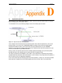
Hysteresis operation
The hysteresis of an analog inputs defines a band in which the previous alarm status is retained
before changing the current alarm status.
To understand its use, the following change curves of an analog input is shown.
Figure 43 – Hysteresis in the maximum limit
As an example we will assume that the maximum limit is 9.0V and the hysteresis is 0.5V. In the
previous figure you can see the “MAXIMUM ALARM” message is sent when the analog signal
exceeds the maximum value, in this case when the input exceeds the 9.0V, the “NORMAL
STATUS” is sent when the analog signal is below the maximum limit minus the hysteresis. In this
case it would be when it goes below the 8.5V.
Having a value of hysteresis prevents from sending repeated messages every time that passes
through this limit is the analog signal is varying arround of maximum limit.
The value of hysteresis must adapt to your needs, a very small value of hysteresis can produce
repeated alarms by maximum and normal status, on the contrary a very large value can produce a
loss of events of a not so significant magnitude.
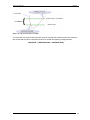
For the lower limit case the following figure shows the behavior, in which you can clearly visualize
that hysteresis is applied when the analog signal goes from its lower limit to a normal value.
www.exemys.com
Rev. 2.3.0 – Dic 2011
42
GTS’ User’s Manual
Exemys
Figure 44 – Hysteresis in the lower limit
You must take into account that hysteresis must be less than the maximum minus the minimum;
this means that the value of hysteresis should not exceed the opposing configured limits.
Hysteresis < (Maximum limit – Minimum limit)
www.exemys.com
Rev. 2.3.0 – Dic 2011
43
GTS’ User’s Manual
Exemys
E Factory default values
Parameter
Description
Value
Password for the reception of SMS
Parse mode
Telephone to which events are
reported
Filter list by telephone number
Activates the filter list by telephone
number
empty
Speed of communication
Number of bits of each datum sent
or received
Error checking
Control of reception buffer
Determined the behavior of the
serial port
Time criterion for packing
End character criterion for packing
9600
8
None
Activated
Transparent
Input name
Input activation
DinputN
Deactivated
Output name
Activation to follow the analog input
DoutputN
Deactivated
Input name
Minimum value for trigger
Maximum value for trigger
Trigger hysteresis
Input enabling
AinputN
1.0
9.0
0.5
disabled
Text in the event of off-on edge
Text in the event of on-off edge
Input enabling
Input N off-on edge
Input N on-off edge
disabled
Text to activate an output
Text to deactivate an output
Response text to activation of an
output
Response text to deactivation of an
output
Turn on N output
Turn off N output
Output N turned on
Basic configuration
Password
Mode
Receipt telephones
List filter
Filter activation
Standard
empty
empty
Deactivated
Serial port configuration
Baud rate
Data bits
Parity
Flow control
Serial port mode
Window time
End character
50
10 (disabled)
Digital inputs (Standard)
Name
Activation
Digital outputs (Standard)
Name
Follow analog
Analog inputs (Standard)
(*)
Name
Minimum
Maximum
Hysteresis
Enable
Digital inputs (Custom)
Off-on edge
On-Off edge
Enable
Digital outputs (Custom)
Activate
Deactivate
Response to activation
Response to deactivation
Output N turned off
Analog inputs (Custom)
(*)
www.exemys.com
Rev. 2.3.0 – Dic 2011
44
GTS’ User’s Manual
Exemys
Minimum
Maximum
Hysteresis
Minimum message
Minimum value for trigger
Maximum value for trigger
Trigger hysteresis
Message when it enters below the
minimum
Normal message
Message when it enters in normal
value
Maximum message
Message when it enters above the
maximum value
Enable
Input enabling
(*) Only for models GTS3002 and GTS3003
www.exemys.com
Rev. 2.3.0 – Dic 2011
1.0
9.0
0.5
AI N below minimum
AI N is normalized
AI N over minimum
Disabled
45
GTS’ User’s Manual
Exemys
F Power Supply and Inputs/Outputs connections
The minimum and maximum admissible values in inputs as well as current and voltage outputs,
and consumption of GTS are detailed below:
Power Supply
Parameter
Input voltage
Consumption idle
Consumption in
transmission
Condition
GTS
GTS
GTS
GTS
at
at
at
at
24
12
24
12
Vdc
Vdc
Vdc
Vdc
Minimum Maximum
10
30
25
40
1
1
Units
Vdc
mA
A
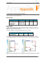
Digital inputs
In order to activate digital inputs an external continuous voltage must be applied. This power
supply has to share the GND terminal with the GTS power supply. If necessary, the same power
supply used to power the GTS can be used.
The input is sinking type. It accepts PNP sourcing type sensors or devices.
Parameter
Activated input
Input impedance
Minimum
3.5
2
Maximum
28
Units
Vdc
KΩ
Two examples of how to connect directly from the same power source of the GTS as well as an
external power supply where it can be seen that they must share a common terminal are shown.
Figure 37 - Digital input with single power supply Figure 38 - Digital input with double power supply
www.exemys.com
Rev. 2.3.0 – Dic 2011
46
GTS’ User’s Manual
Exemys
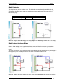
Digital Outputs
The digital outputs are open collector type. The load to be connected must be supplied with and
external power supply and they have to share the same GND terminal with the GTS power supply.
If necessary, the same power supply to power the equipment can be used. The output is of the
NPN sourcing type.
Parameter
Supported voltage
Current
Minimum
Maximum
45
50
Units
Vdc
mA
Figure 39 – Digital output with single power supply Figure 40 – Digital output with double power supply
Digital output to drive a Relay
When used one digital output is used to a relay is necessary add in the connection a protection
diode to avoid damage in the equipment. The diode must be connected in reverse (the anode to
the output terminal of the equipment and the cathode to the positive terminal that feeds the
relay).
The relay must be feed using a external power supply, sharing the GND terminal to the power supply of
the equipment, or if necessary you can use the same source which feeds the GTS.
Figure 41 - Output with relay (single power suply) Figure 42 - Output whit relay (double power suplly)
www.exemys.com
Rev. 2.3.0 – Dic 2011
47
GTS’ User’s Manual
Exemys
Analog Inputs
The analog inputs are referred to the GND terminal of the GTS, so the power supply to feed the
sensor must share the GND terminal with the GTS.
GTS3002
Parameter
Bottom of scale
Precision
Tolerance
Input impedance
Value
10.00
0.01
±0.2
13.3
Units
Vdc
Vdc
full scale %
KΩ
Two examples of how to connect an analog input of voltage for a single power supply and for
independent power supplies are shown below.
Figure 43 – Analog for a single power supply
www.exemys.com
Figure 44 – Analog for a double power supply
Rev. 2.3.0 – Dic 2011
48
GTS’ User’s Manual
Exemys
GTS3003
Parameter
Bottom of scale
Precision
Tolerance
R of shunt
Value
20.00
0.01
±0.4
124
Units
mA
mA
full scale %
Ω
Two examples where you can see the connection of a 4 – 20 ma sensor sharing the power supply
with the GTS for passive sensors or for active sensors with independent power supply are shown
below.
Figure 45 – Analog for a passive sensor
www.exemys.com
Figure 46 – Analog for an active sensor
Rev. 2.3.0 – Dic 2011
49