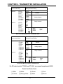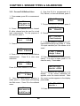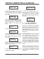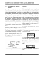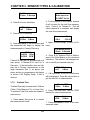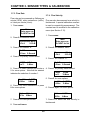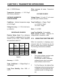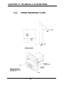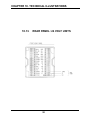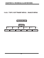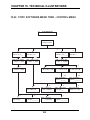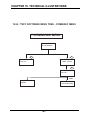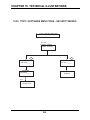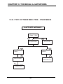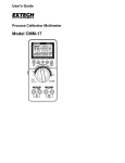
1
Part No. 84263
INSTRUCTION MANUAL
770PC
PROCESS CONTROLLER
TABLE OF CONTENTS
CHAPTER 1. GETTING STARTED
7
1.1.
1.2.
1.3.
1.4.
1.5.
1.6.
Introduction
Start Up - Powering up the 770PC
Operating Modes
Display
Numerical Entries
Menus
7
8
8
9
11
1.7.
1.6.1 Top Level Options
Helpful Hints
12
13
12
CHAPTER 2. TRANSMITTER INSTALLATION
2.1.
2.2.
2.3.
Unpacking
Panel Mounting Cut-Out and Installation
2.2.1. Wall/Pipe Mounting & Installation
Electrical Connections
CHAPTER 3. SENSOR TYPES AND CALIBRATION
3.1.
3.2.
3.3.
3.4.
Cell Constants
Measurement Types and Process
Compensation
Resistivity/Conductivity Measurements
3.4.1 TDS
3.4.2. TDS Multiplier
3.5
pH/ORP Measurement
3.5.1. Calibration
3.5.2 pH Sensor Diagnostics
3.5.3. pH Measurements - Advanced Features
3.5.4 Setting UP and STC Factors for pH
3.6. Pressure Measurements
3.6.1. Differential Pressure
3.6.2. Tank Level
3.6.3. Percent Full/Gallons/Liters
3.7. Flow Measurements
3.7.1 Percent Recovery - Reverse Osmosis
3.7.2. Totalized Flow
3.7.3. Flow Rate
3.7.4. Flow Velocity
3.8. Sensor Calibration
3.8.1. One Point Calibration
3.8.2. Two Point Calibration
3.9. Changing Sensor Calibration Constants
3.10. Entering the Inside Pipe Diameter
3.11. Saving Calibration Data
3.12. Optional +24VDC Sensor Power Supply
3.12.1. Installing the +24V Module to the 770PC
3.12.2. Attaching a Patch Cord to the +24 Volt Supply
15
15
15
15
16
19
19
20
21
21
21
22
23
23
23
24
24
25
25
25
26
27
28
29
29
30
31
31
32
32
33
34
35
34
35
TABLE OF CONTENTS
CHAPTER 4. OUTPUT OPTIONS
4.1.
4.2.
4.3.
4.4.
Analog Output Set Up
Analog Outputs
Inverting the Analog Outputs
Output Hold Feature
CHAPTER 5. 770PC TRANSMITTER OPERATIONS
5.1.
5.2.
5.3.
5.4.
5.5.
5.6.
5.7.
5.8.
5.9.
5.10.
5.11.
5.12.
5.13.
5.14.
5.15.
Measurement Type Selection
Display Setup
Display Format
Range Selection
Compensating Measurements
Temperature Source
Setpoints
5.7.1. USP Setpoint
Relays
System Reset
5.9.1
Measurement Averaging
Measurement Timing: 50/60 Hz Operation
Percent Rejection - Reverse Osmosis or Ultrafiltration
Security Password/Lockout Menus
Smart Automatic Transmitter Calibration
5.14.1. Resistance/Temperature Calibrator
5.14.2. Voltage Calibrator
5.14.3. Calibration Procedure
Using the Function Key
CHAPTER 6. NETWORKING
6.1.
6.2.
6.3.
6.4.
6.5.
6.6.
Lan Capabilities and Applications
Lan Features
Lan Guidelines
Remote Control Mode
Changing a Transmitters Address For Instruments
With Software Earlier Than Version 2.0
Setting the Network Address For Instruments
With Version 2.0 Software Or Later
CHAPTER 7. SERVICE
7.1.
7.2.
7.3.
7.4.
7.5.
7.6.
7.7.
Fuse Replacement
770PC Software Upgrade Microprocessor Replacement
Recommended Spare Parts List
Accessories
Optional Output Printed Circuit Boards
Nema 4X Rear Cover
Troubleshooting
39
39
39
41
41
43
43
44
45
46
46
48
49
50
51
53
53
53
54
54
56
58
58
58
59
60
63
63
63
64
64
66
67
69
69
70
72
72
72
72
73
TABLE OF CONTENTS
CHAPTER 8.
CHAPTER 9.
TECHNICAL SPECIFICATIONS 770PC
MODEL NUMBERS
77
9.1.
77
77
77
75
78
78
9.2.
CHAPTER 10.
WARRANTY
75
Transmitters
9.1.1. Blind
9.1.2. Full Display
9.1.3. Gateway
Patchcords
9.2.1. Sensor Patchcords with 8 Pin Female
AMP to Tinned Leads
9.2.2. T-NET Local Area Network (LAN) with 4 Pin Female
AMP to Tinned leads
9.2.3. T-NET Local Area Network (LAN) Accessories
78
78
TECHNICAL ILLUSTRATIONS
79
10.1. 770PC Overall Dimensions
10.2. 770PC Exploded Assembly
10.3. Rear Mounting
10.4. Front Mounting 1/4 DIN
10.5. Pipe/Wall Mounting Bracket Dimensions
10.6. Pipe/Wall Mounting
10.7. Pipe/Wall Mounting
10.8. Nema 4X Rear Cover Dimensions
10.9. Nema 4X Rear Cover Exploded Assembly
10.10. 770PC Measurement Board
10.11. 770PC Analog Output Conversion
10.12. 770PC Patch Cord Wiring
10.13. Rear Panel: 24 Volt Units
10.14. LAN Cables and Terminations
10.15. Smart Sensor Calibrators
10.16. Menu Tree - Main Menu
10.17. Menu Tree - Measure Menu
10.18. Menu Tree - Display Menu
10.19. Menu Tree - Calibrate Menu
10.20. Menu Tree - Time/Average
10.21. Menu Tree - Compensation/Temp Menu
10.22. Menu Tree - Range Menu
10.23. Menu Tree - Control Menu
10.24. Menu Tree - Communication Menu
10.25. Menu Tree - Security Menu
10.26. Menu Tree - Other Menus
80
81
82
83
84
85
86
87
88
89
90
91
92
93
94
95
96
97
98
99
100
101
102
103
104
105
107
CHAPTER 1. GETTING STARTED
Thank you for ordering the 770PC from modem or personal computer.
Thornton. The 770PC instrument is user
friendly, flexible and highly accurate. It is The following is the current list of paramean analytical and process control instru- ters measured:
ment for measuring solution properties.
Resistivity
The 770PC is a two channel device which
Conductivity
can process four different measures simulTDS (ppm as NaCl)
taneously. A three line vacuum fluorescent
% Rejection
display indicates measurements and setup
Temperature
information. A menu structure allows the
pH/mV
operator to modify all operational parameFlow Rate (∆ flow)
ters from the 15-key keyboard. The 770PC
Flow Velocity
is equipped with two relays for process
% Recovery
control.
Pressure (∆P)
Tank Level
A 770PC with patented Smart Sensors™,
%HCI
provides highly accurate monitoring and
%NaOH
control, measuring multiple parameters
%H2SO4
with one instrument using different sensors. Each sensor contains a NVRAM
(nonvolatile random access memory) 1.1. INTRODUCTION
which stores: sensor type, calibration data,
date of calibration and serial number. The The 770PC and Smart Sensors can be
sensor type and stored information are operated without a User Manual or special
identified by the transmitter, which auto- training. Utilizing Thornton’s Smart Senmatically compensates for manufacturing sors, the 770PC will automatically detervariables for that particular sensor. The mine the type of sensor installed, make the
result is improved accuracy for resistance appropriate measurement and display the
of ±0.3% of meter readings for resistance measurement in a conventional manner.
measurements (see specifications).
The keypad is used to achieve special
Transmitters can be connected on Thornton’s 2-wire Local Area Network (LAN),
which connects separate dual channel
instruments on a single transmission line.
Any transmitter can be monitored or reprogrammed by any other transmitter, for
process monitoring or control. An RS-232
output provides real-time data with a
7
results. However, with a little extra effort
the instrument can be customized to measure and display an amazing variety of
data. This section will explain the basic
methods of operating the instrument and
later sections will elaborate on details.
CHAPTER 1. GETTING STARTED
A “System Reset” will clear all user programming and will return the 770PC to facRead all of “Getting Started” prior to using tory default settings. If the 770PC meter
this instrument or sensors. The menu-dri- does not display the expected measureven software accessed by the keypad con- ments, do a “System Reset” as follows:
trols will guide the user through the various
1: Press menu, then press 9 for a system
operations.
reset
The following steps must be completed
prior to “start up”.
Main
Enter menu no.
• Installation - Section 2.0
Or NEXT for list
• Electrical - Section 2.0.3
• Sensor Installation & Maintenance
2. Press 2
Section 3.0
Read This First
1.2. “START UP” - POWERING
UP THE 770PC
1-Measure Reset
2-System Reset
Install one patch cord for each sensor, connect two sensors, turn on the power and
momentarily the unit will begin to display
the startup messages: (1) display software
version #, (2) measurement software verTM
sion #. If a Smart Sensor is not connected to a channel, the unit will (3)
request its type. After the user describes
the non-Smart Sensor, the 770PC will
enter normal measurement mode.
3. Press 1
1-System Reset
2-Return
The System Reset is now complete. If the
measurements do not display as expected,
see “Troubleshooting”, Section 7.04
1.3. OPERATING MODES
The 770PC will query the Smart Sensor(s) to determine sensor type and calibration constants. If the 770PC is being
used for the first time, the default units and
autoranging functions are used to display
the measured data in a suitable manner.
The 770PC automatically reads the data
from the Smart Sensor and displays the
measurement.
8
Measurement Mode - measurements are
performed and the display is updated at
one second intervals.
Menu Mode - a list of program options or
calibration parameters is displayed.
CHAPTER 1. GETTING STARTED
Measurements are not displayed in the
menu mode, but are transmitted and measured.
All functions (e.g. set points,
relays, data transmission, etc.) are operating.
are properly installed, the sensors will
identify themselves, by sensor type and
measurement data, to the transmitter
which translates the information into the
display format. The Measurement Mode is
automatically activated upon start-up.
Use the menu key to enter the menu
mode. Press exit menu to return to the Each line of the display can be programmed to display a fixed number of digmeasurement mode.
its after the decimal place. This feature is
1.4. DISPLAY
useful when a reading is fluctuating and it
is desired to display only the significant
Each line of the three line vacuum fluo- digits (see section 5.03)
rescent display can be programmed to
display any of four measurements. The A Typical Display:
top line contains five characters and will
18.18
display only the numerical measurement.
A 18.18 Mo-cm C
Its purpose is to allow the viewing of data
B 59.2 PSI
at a distance. The second and third lines
each contain 16 alphanumeric characters
which display the measurement type, the The top line of the display shows a resismeasurement value, units, and compensa- tivity reading of 18.18 Mohm-cm (Channel
A primary). The channel and units for this
tion state (if applicable).
measurement are not shown. The second
In the measurement mode, the measureline shows the Channel A Primary meament is indicated by one character:
surement (indicated by the first character
Channel
Explanation
“A”) of 18.18 Mohm-cm. This measurement is compensated for temperature as
“A”
channel A primary
“a”
channel A secondary indicated by the character “C” at the end of
“B”
channel B primary
the line. The third line shows the Channel
“b”
channel B secondary B Primary measurement (indicated by the
character “B”) of 59.2 PSI (pressure).
Capital letters: “A” & “B” indicate Primary
measurement channels for A&B
Lower case letters: “a” & “b” indicate Secondary measurements for channels A&B
When the power and sensor connections
9
Press next to toggle the display to show
the alternate measurements. For example,
if line 2 shows the Channel A Primary measurement pressing next will show the
Channel A Secondary measurement.
CHAPTER 1. GETTING STARTED
• pH in the range 0 to 14
• Volts, millivolts, or microvolts
• Temperature in degrees Celsius or
Fahrenheit
25.00
a 25.00 Deg C
b 408.3 kPas
Line 1 and 2 display Channel “a” (Secondary Measurement) for resistivity, tem- ORP (Oxidation Reduction or Redox Potential)
perature in degrees Celsius. Line 3 dis- Sensor:
plays Channel “:b” (Secondary Measure- • Measurement in millivolts
ment) for pressure in kilo Pascals (metric).
Flow Sensor:
Measurement Types
• Total flow in gallons, liters, or cubic
meters
770 Series Instruments are capable of • Flow rate in gallons/min, liters/min or
3
measuring Primary and Secondary para- meter /hour, Frequency
meters on each of two channels, designat- • Velocity in feet/second
ed A and B. The user can specify through
menus which parameters are primary and Pressure Sensor:
which are secondary. In addition, dis- • Gauge pressure in PSI, millimeters of
played results can be computed from a mercury, kilo Pascals or voltage
combination of measurements made on • ∆ Pressure
both channels (see section 5.01).
Tank Level Sensor:
Measurements depend on the type of sen- • Volume of liquid in cubic meters, liters,
sor connected. The following is a list of gallons or % full
options.
Temperature Sensor:
Conductivity Sensor:
• Conductivity in mS/cm, µS/cm, nS/cm.
• Resistivity in ohm-cm, kohm-cm, Mohmcm
• Total Dissolved Solids, TDS, in kppm
(ppt), ppm, mppm (ppb).
• Temperature in degrees Celsius or
Fahrenheit
• Temperature in degrees Celsius or
Fahrenheit
Chemical Sensor:
•
•
•
•
Resistivity, conductivity, temperature
%HCI
%NaOH
%H2SO4
Keypad & Menu Software
pH Sensor:
10
CHAPTER 1. GETTING STARTED
returns to the previous menu
The 15 key keypad provides a flexible control with few keystrokes. Here is a brief
summary of what the keys do. Try a few of
them!
The two most important keys on the keypad are exit menu and menu.
function is used to access special data
and information.
menu enters the menu structure from the
measurement display.
The exit menu key is used to escape from mode enters the menu at the Measure
recall
enter
store
start
menu.
7
8
exit
menu
menu
4
calc
5
time
6
next
–
mode
0
display
1
control
2
sensor
3
function
next steps through menu options or toggles displayed data.
recall is a feature that will be implemented
in the future.
•
the menu structure and return to measuresensor enters the menu at the Range
ment display.
menu.
The menu key allows the user to enter the
start is a feature that will be implemented
main menu structure.
in the future.
0..9, •, and – are used to select menu items
store is a feature that will be implemented
or to enter data.
in the future.
‹— (Backspace or Clear) retracts an time is a feature that will be implemented
entered number or moves up one level in in the future.
the menu.
calc is a feature that will be implemented in 1.5. NUMERICAL ENTRIES
the future.
Numbers may be entered with up to 5 digcontrol enters the menu at the Control its (including an optional decimal point, and
menu (setpoints, relays and signal out- an optional negative sign). When making a
puts).
numerical entry press <- to clear the digits
entered and press enter to accept the
display enter the menu at Display setup.
number. After pressing enter, the number
enter accepts data entry, a second enter entered will be displayed on the second
11
CHAPTER 1. GETTING STARTED
line if it is accepted. “enter” must be
pressed again to leave the menu and
return to the previous menu.
Main
0-Measure Menu
1-Display Menu
1.6. MENUS
Current Settings are indicated by an
asterisk “*” preceding the menu number.
For example, the menu for setting the
range of a resistivity measurement may
appear as:
Menus are arranged in a tree-like structure
which will allow complete control of all
770PC features. Menu options can be
cycled through or specific items can be
selected. Try pressing various keys to see
how the menu mode works. When finished
1: Auto *2:Mo-cm
using the menu, press exit menus to exit.
3:Ko-cm 4:o-cm
A tree diagram of the menu structure is
located in the back of this manual.
The “*” preceding the selection “2:Mo-cm”
shows that the meter is set to display resisPress menu, then press next to cycle tivity in Mo-cm units. Pressing “3” would
through all of the top level menu options. cause the “*” to move to “3:Ko-cm”.
To back up, press <-. Use exit menus to
exit the menu mode. A complete list of all 1.6.1. Top Level Options
options is located in the Menu Options section of this manual. The top level options 0
measure: For measurement
for getting started are listed below.
selection
NOTE: If you are entering data the
enter key must be pressed twice
to return to menu mode.
Press menu:
1
display: For display formatting
2
calibrate: Begins a calibration
sequence
3
time/averaging: is used to set the
amount of measurement damping
or averaging.
4
comp/temp: For selection of
compensation parameters or
temperature source.
Main
Enter menu no.
Or NEXT for list
Any of the top level menus can be entered
by pressing a numerical key from 0 to 9.
Pressing next will list the first two options: 5 range: For selection of a specific range
12
CHAPTER 1. GETTING STARTED
5
range: For selection of a specific
range or autoranging.
6
control: For changing setpoint
values.
7
8
compatible with one of the meter’s operating modes. Please contact Thornton Associates for more information.
5) When a menu reads “enter” the enter
key must be pressed a second time to
leave that menu.
communc: For obtaining network
(LAN) information and accessing
the remote control features.
6) Pressing exit menu will always return to
measurement operations.
security: For enabling/disabling the
menu lockout feature and changing 7) Remote Control Mode is available (see
Section 6.0, Networking).
the password.
other: For measurement or system 8) Averaging allows a user to program the
770PC to average measurements for stareset.
bilized readings (See Section 5.10., Mea1.7. HELPFUL HINTS
surement Averaging).
9
1) Analog option: two 4-20mA outputs or
two 0-10 volt outputs. The user must
assign the desired parameters to the output signals (See Section 4.0., Output
Options).
2) Transmitters can be connected together
to form a network system (see Section 6.0,
Networking).
3) Relays and Setpoints: two relays and
four setpoints are available. The user must
assign the desired parameters (see Section 5.0, 770PC Transmitter Operations).
4) Transmitters have two sensor inputs.
Two sensors may be connected to the unit.
These may be either Thornton Smart Sensor or any other sensor whose output is
13
14
CHAPTER 2. TRANSMITTER INSTALLATION
two mounting retaining screws (see 770PC
Front Mounted in 1/4 DIN Panel Opening”
Each 770PC is packed in an individual illustration in the rear of this manual.
biodegradable carton. Customers are
advised to retain packaging in the event
CAUTION: Turn the mounting
that the instrument must be returned to
retaining screw counterclockThornton Associates for service. Open
wise until the meter is tight
cartons carefully to insure that products
against the panel. Tighten the
are not damaged or dropped.
second mounting retaining screw
2.1. UNPACKING
counterclockwise until tight. Verify that both screws are tight and
the meter is firmly mounted to the
panel.
Carton contents:
1-770PC Transmitter
1-Manual
2.2.1. Wall/Pipe Mounting & Installation
2.2. PANEL MOUNTING
CUT-OUT AND
INSTALLATION
Panels must have openings cut to 3 5/8” X
3 5/8” (92mm x 92mm, 1/4 DIN). Take note
of transmitter case dimensions to insure
proper spacing on panels for multiple bezel
clearance, if more than one transmitter is
mounted on a panel.
Panel cutouts must be clean and free of
burrs and sharp edges. The proper dimensions allow a transmitter to slide freely into
the cutout.
WARNING: PIPE MOUNTING IS
NOT RECOMMENDED IF THE
PIPE IS SUBJECT TO VIBRATION.
A versatile Wall/Pipe mounting bracket
(part number 15533) is available for various mounting locations. A 3.625” X 3.625”
(92mm X 92mm) 1/4 DIN cut-out is provided for installing the instrument on this right
angle painted aluminum bracket. Four
mounting holes are provided for securing
the bracket to a flat surface or around a
pipe. Four slots are also provided for fastening with banding tape, worm clamps or
other fastening hardware.
If the NEMA 4X Rear Cover is used in a
panel mounted installation, the 770PC unit
must be installed in the panel opening Slide the meter into the cutout. From the
before the NEMA 4X Rear Cover is rear of the meter, insert a long slotted
screwdriver into on of the two mounting
installed.
retaining screws (see 770PC Front MountInstall panel gasket, slide the meter into ed in 1/4 DIN Panel Opening” illustration in
the cutout. From the rear of the meter, the rear of this manual). Turn the mounting
insert a long screwdriver into one of the retaining screw counterclockwise until the
15
CHAPTER 2. TRANSMITTER INSTALLATION
meter is tight against the panel. Tighten
the second mounting retaining screw counterclockwise until tight. Verify that both
screws are tight and the meter is firmly
mounted to the bracket.
2.3. ELECTRICAL CONNECTIONS
Make all electrical connections to the rear
of the transmitter case. Connections must
be made with one sensor patch cord (see
Section 9.0 How to Order) for each sensor
input.
Cables provide an interface
between the eight pin AMP Smart Sensors
connector and the transmitters terminal
strip.
LAN, analog outputs, relay contacts and
power input connections must be installed
as illustrated below.
NOTE: A microprocessor reset
switch may be installed on the
transmitter. To add a microprocessor reset switch, install a
momentary switch between the
RESET position and Sensor A or
B Analog Ground (AG) position
on the rear terminal strip as
shown below.
16
WARNING: MISWIRING PATCH
CORDS MAY DAMAGE SENSORS
AND WILL VOID ALL WARRANTIES! ALL WIRES MUST BE
CONNECTED. EACH SENSOR
PATCH CORD WIRE IS NUMBERED TO MATCH A NUMBER
ON THE REAR LABEL. TO VERIFY WIRE COLOR AND NUMBER,
CHECK TABLE BELOW.
NOTE: For CE-rated models 772209 and 772-219, see manual supplement 84350.
CHAPTER 2. TRANSMITTER INSTALLATION
Network, Analog Outputs,
Relays & Power Wiring
Sensor Lead Wiring
Sensor B
(8) VCC
(7) -VAN
(6) DA
(5) CLK2
(4) AG
(3) SIGB-3
(2) SIGB-2
(1) SIGB-1
Sensor A
(8) VCC
(7) -VAN
(6) DA
(5) CLK1
(4) AG
(3) SIGA-3
(2) SIGA-2
(1) SIGA-1
RESET
LANLAN+
AOUT1
AGND1
AOUT2
AGND2
NC1
NO1
C1
NC2
NO2
C2
Network
Analog Outputs
Relay Contacts
-Black
-White
-Green
L
N
Power
Input
Rear Panel Wiring Sequence: 115/230VAC Units
Network, Analog Outputs,
Relays & Power Wiring
Sensor Lead Wiring
Sensor B
Sensor A
(8) VCC
(7) -VAN
(6) DA
(5) CLK2
(4) AG
(3) SIGB-3
(2) SIGB-2
(1) SIGB-1
(8) VCC
(7) -VAN
(6) DA
(5) CLK1
(4) AG
(3) SIGA-3
(2) SIGA-2
(1) SIGA-1
RESET
LANLAN+
AOUT1
AGND1
AOUT2
AGND2
NC1
NO1
C1
NC2
NO2
C2
Network
Analog Outputs
Relay Contacts
+24V
RET
-Black
-White
-Green
Power
Input
Rear Panel Wiring Sequence: +24VDC Units
For CE-rated models 772-209 and 772-219, see manual supplement 84350.
Patch Cord Color Code:
(1)-Blue
(2)-Yellow
(3)-White
(4)-Orange/Clear
(5)-Green
(6)-Black
17
(7)-Pink
(8)-Brown
18
CHAPTER 3. SENSOR TYPES & CALIBRATION
Smart Sensors can be connected to this
unit. Thornton’s Smart Sensors are produced under license from Tektronix, Inc.
U.S. Patent 4,672,306. Smart Sensors
contain a nonvolatile memory integrated
circuit (NVRAM) in the cell housing that
stores the sensor type, serial number, calibration data, and date of calibration. Sensor types available for use with the 770PC
are:
1.
2.
3.
4.
5.
6.
7.
8.
9.
Conductivity (Resistivity)
pH/ORP
Pressure
Flow
Tank Level
Temperature
Voltage
Frequency
Chemical
revert to the default settings.
3.1. CELL CONSTANTS
Each sensor is defined by a set of calibration constants, also known as sensor constants. The two constants, a Multiplication Factor and an Adder Factor, are
used to derive an accurate measurement
from the sensor’s output signal Equations
vary by sensor type, as an example, the
output of a resistivity sensor can be represented by an equation describing a straight
line:
R=x/a1 + a2
Where:
R=resistivity value
a1=multiplier factor
x=output from cell
a2=adder factor
NOTE: Refer to each specific sensor manual, provided with each
sensor, for complete details on
installation, troubleshooting and
service.
An example: for a 0.1 constant resistivity
sensor the multiplier factor (a1) is 0.1 and
the adder factor (a2) is 0. If the sensor output is 120,000 ohms then the actual resisWhen power is first applied, the 770PC tivity of the solution measured is 1.2
determines the sensor type attached to Mohm-cm and is computed as follows:
each channel. If a Smart Sensor is
R=x/a1+a2
detected, calibration data is read. If the
R=120,000/0.1 + 0
unit does not detect a Smart Sensor it will
R=1,2,000,000
ask for the type of cell to be entered from a
R=1.2 Mohm-cm
list shown on the display. The operator
must select a sensor type. Thereafter, the
NOTE: For many sensors, such
unit will read the sensor every second. If a
as resistivity, the adder factor
new Smart Sensor is installed, the new
may be zero.
calibration data will be read. If the sensor
is removed or a non-Smart Sensor is
The calibration constants can be modified
installed, unit calibration constants will
19
CHAPTER 3. SENSOR TYPES & CALIBRATION
from the menus.
3.2. MEASUREMENT TYPES
AND PROCESS
Pressure
PSI
kpascals
The 770PC has two channel inputs for mm Hg
installing sensors. Up to four measure- Differential Pressure
ments can be continuously processed at Voltage
one second intervals (two measurements
from each sensor). Channel display: Each
channel (A and B) has a primary measurement indicated by “A” and “B”, and a secORP
ondary measurement indicated by “a” and
millivolts
“b” in the “display mode”.
When programming the software in the
“menu mode”, the primary measurements
are indicated as “Ap” and “Bp”, secondary
measurements as “As” and “Bs”.
Tank Level
% Full
total gallons
Liters
PSI
Each of the four measurements can be Chemical
Resistivity
Display
Menu Explanation
Conductivity
Mode
Mode
Degrees C
“A”
Ap
channel A primary
Degrees F
“a”
As
channel A secondary
% NaOH
“B”
Bp
channel B primary
%HCl
“b”
Bs
channel B secondary
%H2SO4
assigned a specific measurement parameter from a list that is applicable to the Voltage
installed sensor. Current measurement PSI
kpascals
parameters available:
mm Hg
Differential Pressure
Conductivity
pH
Voltage
Resistivity
pH
Conductivity
TDS
Degrees C
Degrees F
% Rejection
Voltage
Degrees C
Degrees F
20
Flow
Gal/min
m3/hr
total flow
% Recovery
Differential Flow
Liters
Gallons
Liters/min
Feet/second
Temperature
Degrees C
Degrees F
Frequency
Gal/min
m3/hr
total flow
% Recovery
Hz
CHAPTER 3. SENSOR TYPES & CALIBRATION
3.3. COMPENSATION
3.4. RESISTIVITY/CONDUCTIVITY
Measurements, such as resistivity, conducMEASUREMENTS
tivity and pH, can be compensated for temperature. For example, the resistivity of
pure water at 25 degrees C is 18.18
Megohm-cm. Yet the resistivity of ultrapure water at 30 degrees C is 14.08
Megohm-cm. By compensating the resistivity reading, the value of pure water will
always read 18.18 Megohm-cm. Compensating a measurement is selected in the
menu and is indicated on the display with
the letters “C” for a compensated measurement or “U” for uncompensated measurement, shown after the measurement
units. The source of temperature compensation can be from:
• The channel making the
measurement
• The other channel
• A manually entered value
3.4.1. TDS
Total Dissolved Solids (TDS) is another
useful way to measure and display conductivity/resistivity data. TDS is the equivalent of Sodium Chloride (NaCl) required
to produce the measured resistivity. TDS
is measured in parts per billion (ppb) or
parts per million (ppm). For this example
the display would show a TDS of 10 ppb or
0.01 ppm, where 1 ppm equals 1 milligram
per liter.
1: Press menu, then press 0 for the measurement menu.
Main
Enter menu no.
Or NEXT for list
2. Select channel A or B, as either channel
If the sensor has a temperature sensor maybe used for a TDS measurement.
(RTD) installed within the sensor housing Press 1 for channel A.
then “compensate from this channel” can
Measurement Mode
be used. If the sensor on the other chan1-Ch A
2-Ch B
nel is a temperature sensor or has an internal RTD, then “compensate from the other 3: Press 1.
channel” can be used. Manual compensation can be entered from the keypad when
Ch A Measurement
no temperature remains constant (see sec1-Prime 2-Second
tion 5.05 and 5.06).
4: Press 3 to select TDS, notice that the
asterisk moves to that selection.
21
CHAPTER 3. SENSOR TYPES & CALIBRATION
1-Res
*3-TDS
2-Con
9-More
A: Calib 1-Edit
2-Do
3-Save/Clr
5: Press exit menu to exit the menus and 3: Press 1 to edit the TDS Multiplier.
Edit
1-Cell Con
return to the display.
2-Temp 5-TDS M
NOTE: A sensor installation on
channel A should now display
that sensor information. If there
is any uncertainty about channel
A or B primary or secondary programming see Section 5.02 Display Setup.
4: Press 5 to select the TDS Multiplier .
A: TDS M =.0000
Enter No: XXXX>
5: Enter the TDS Multiplier from the table
below:
3.4.2. TDS Multiplier
TDS Multipliers (normalized to NaCl)
The default setting with TDS multiplier set
at zero provides conversion based on sodium chloride at approximately 0.5 ppm per
µS/cm but is non-linear. Changing the TDS
multiplier results in that number being multiplied by the sodium chloride factor. For
conversion of other materials, see table
below. The Total Dissolved Solids (TDS)
Multiplier Factor can be used to adjust all
TDS measurements when either a one
point calibration is used with NaCl, or for
measuring solutions other than NaCl.
1: Press menu, then press 2 for the calibration menu
Calibrate Menu
1-Ch A
2-Ch B
KCl:
CaCl2:
CaCO3:
NaOH:
1.07865
0.8839
0.8407
0.3480
6: Press enter and the new TDS multiplier
value will be displayed on the top line. If
the displayed multiplier value is correct,
press enter to verify the correct value and
exit. If the Multiplier number is incorrect,
enter a new number and press enter twice.
A: TDS M = XXXX
Enter No: >
7: Press exit menu to return to the measurement mode
2: For the purpose of this manual press 1
to select channel A:
22
CHAPTER 3. SENSOR TYPES & CALIBRATION
Calibration Procedure
3.5. PH/ORP MEASUREMENTS
Select the “two point” calibration option
from the calibration menu. The buffer soluDue to aging in the process, pH Smart tion and the electrode should be at the
Sensors require recalibration after a peri- same temperature. See section 3.08.
od of time. The stability of the sensor
depends entirely on the nature of the samNOTE:
ple solution, pressure temperature, etc.
• Stirring the solutions ensures
For this reason, calibration intervals
a quicker response.
should be based on experience with the
• Do not rub the glass electrode
particular application.
membrane when dry, since it
3.5.1. Calibration
When measuring solution not previously
measured, it is advisable to recalibrate frequently. If no significant variation is found,
the calibration interval may be increased.
will create electrostatic
charges on the glass
membrane, which causes a
delayed response.
3.5.2. pH Sensor Diagnostics
Materials and Equipment Needed for
The Additive Factor (standardize offset) is
Calibration
an indicator of how far the sensor has driftFor proper calibration, two buffer solutions ed from the nominal zero starting point, in
of adequate accuracy and pH range are pH units. It is recalculated after every calinecessary. Each buffer solution should be bration. Drift in this value is usually due to
poured into a small beaker to approximate- aging or contamination of the reference
ly 1” depth to immerse the electrode tip. electrode portion of the sensor.
One buffer solution is usually at or near 7
pH. The buffer solutions should cover the An offset of more than ±2.5 pH units is an
anticipated measurement range. For indication that the sensor should be
example, if the measurements are expect- replaced soon. The Additive Factor “A” can
ed to be done in acid media, the second be viewed at any time in the Edit Calibrate
buffer should have a pH value of 4.0. If the menu. However, the value must not be
media is expected to be alkaline, the sec- changed in this menu or the sensor will
ond buffer should have a pH value of 9 or have to be recalibrated.
10. The difference between the two caliThe Multiplier (slope or span) is an indicabration buffers should be at least 2.0 pH.
23
CHAPTER 3. SENSOR TYPES & CALIBRATION
tion of the sensitivity of the sensor to
changes in pH. It has a nominal value near
1 and is recalculated after every 2-point
calibration. Reduction in this value is usually due to aging, coating or hot caustic
attack of the glass measuring membrane
of the sensor.
determined by developing temperature vs.
pH data for the particular sample with STC
set at 0. The negative slope of this data
becomes the STC value.
The solution temperature coefficient, STC,
may be changed in the Edit Calibrate
A sensor with Multiplier value less than menu.
0.80 should be replaced soon. The Multiplier “M” can be viewed at any time in the The Isopotential Point, UP is left at 7.0
Edit Calibrate menu. The value must not be pH for all conventional pH electrodes. Spechanged in this menu or the sensor will cial purpose electrodes with zero potential
at values other than 7.0 pH will have this
have to be recalibrated.
identified in their instruction manuals. A different UP setting will allow proper temper3.5.3 pH Measurements-Advanced
ature compensation of these special elecFeatures
trodes. The UP setting is accessed through
The solution temperature coefficient (STC) the Edit Calibrate menu.
allows selection of temperature compensation for the ionization of pure waters. This 3.5.4. Setting UP and STC Factors for
is in addition to the conventional (Nernst) pH
temperature compensation for the sensor
which is always active. Solution tempera- To set the UP or STC factors for a special
ture compensation is used on power plant pH application:
and other pure water samples less than 30
Press Menu.
µS/cm where the changing ionization of 1:
water is significant. It references the pH to
Main
25˚C. In all other applications the STC
Enter menu no.
value is left at zero.
Or NEXT for list
For ammonia, phosphate and/or aminePress 2 for the Calibrate Menu.
treated power plant samples, the solution 2:
temperature coefficient, STC, should be
Calibrate Menu
set to 0.033 pH/˚C. For pure makeup water
1-Ch A 2-Ch B
or boiling water reactor samples, the solution temperature coefficient should be
Select the desired channel. For
0.016 pH/˚C. The appropriate values for 3:
other pure water compositions may be example, press 2 for channel B.
24
CHAPTER 3. SENSOR TYPES & CALIBRATION
Measurement Mode
1-Ch A
2-Ch B
B: Calib 1-Edit
2-Do 3-Save/Clr
4:
3: For the purpose of this example,
press 1.
Press 1 to enter the Edit Menu.
Edit pH: 1-Cell
2-Temp 7-UP 8-SC
Ch A Measurement
1-Prime 2-Second
5:
Press 7 to edit UP factor or press 8
to edit the STC factor. For example, press 4: Press 9 to select more
8 to edit the STC.
1 - PSI
2- KPAS
3-mmHg *9-More
B: STC = .00000
Enter No: >
5: Press 5 to select differential pressure.
4 - Volt
Enter the new STC factor and press the
6-Bars
Enter key when done. The new value will
appear on the top line. Press Enter again
to return to the previous menu.
3.6.2. Tank Level
*5 - Diff
9 - More
3.6. PRESSURE MEASUREMENTS Tank level is measured with a pressure
sensor mounted in the tank. A Smart Sensor will automatically identify the sensor.
3.6.1. Differential Pressure
Non-Smart Sensors are identified by the
If two pressure sensors are installed in a maximum pounds per square inch (psi) ratsystem and a differential pressure calcula- ing each sensor is calibrated for. Tank size
tion is required for the application, use the must be programmed into the software in
the calibration menu by entering tank
following procedure:
height and area.
1: Press menu, then press 0 to enter the
Tank-Percent Full or amount of Gallons or
measurement menu
liters may be measured by the 770PC. By
Main
entering the menus and programming this
Enter menu no.
information, these tank level measureOr NEXT for list
ments may be obtained.
2: One channel A or B will be required to
measure differential pressure. Press 1 to
select channel A.
25
CHAPTER 3. SENSOR TYPES & CALIBRATION
6: Now that Ch A is programmed for %
Full, Gallons, or Liters as selected, press 1:
3.6.3. Percent Full/Gallons/Liters
1: Press menu, press 0 for measurement
mode
Main
Enter menu no.
Or NEXT for list
Calibrate Menu
1-Ch A
2-Ch B
7: To input the tank size constants press 1:
A: 1-Edit Calibrate
2: Press 1 for channel A or 2 for channel
2-Do
3-Save/Clr
B, either channel may be used for a tank
level measurement. For the purpose of 8: Press 4
this manual, press 1.
Edit: 1 - Cell Con
4-Tank Constants
Measurement Mode
1-Ch A
2-Ch B
9: If a Smart Sensor is installed: DO NOT
input maximum psi go on to Step 11. Press
3: Press 1.
1 to input maximum psi if the sensor is not
smart.
Ch A Measurement
1-Prime 2-Second
A: Tank 1- MaxPSI
2-Height 3-Area
4: Press 1 for % Full or 2 for actual Gallons
measurement. Press 9 to view more 10: Enter the maximum psi of the pressure
sensor. If an error is made, press <— to
selections.
clear the entry. Press enter.
*1-% Full
3-PSi
2- Gals
9-More
A:Max PSI=.0000
Press 4 for cubic meters or 5 for liters.
Enter No: > XXXX
The new maximum will now appear in the
display. If the correct maximum psi
appears, enter the correct amount. Once
5: Once the measurement selection is the correct number appears in the display,
made, press <— three times until reaching press enter.
the Main menu. Press 2 for the calibrate
A:Max PSI=.XXXX
menu.
Enter No: >
4-m^3
6-Ft
5-Liters
9 - More
Main
Enter menu no.
Or NEXT for list
11: Press 2.
26
CHAPTER 3. SENSOR TYPES & CALIBRATION
A:Tank 1-Max PSI
2-Height 3-Area
A:Tank 1-Max PSI
2-Height 3-Area
12: Enter the internal tank height in feet. If
an error is made, press <— to clear the
entry. Once the correct data is entered,
press enter.
16: Once the tank area data is programmed into the 770PC, the tank level % full calibration is complete. Press exit
menu to leave the menus and return to display mode.
A:Height=.0000
Enter Ft: > XXXX
XXXX
A XXX.X % Full
a XXXX. Gals
The new tank height will appear in the display. If the incorrect tank height appears,
enter the correct amount. Once the correct
number appears in the display, press 3.7. FLOW MEASUREMENTS
enter.
The 354 and 355 Series Flow Sensors
generate an AC signal, the frequency of
which is proportional to the flow rate. Each
Smart Sensor NVRAM stores the sensor
type and calibration constants of that specific sensor.
A:Height= XXXX
Enter Ft: >
13: Press 3.
A: Tank 1-Max PSI
2-Height 3- Area
14: Enter internal tank area in square feet.
If an error is made, press <— to clear the
entry. Once the correct data is entered,
press enter.
Each Smart Sensor for Flow is calibrated
at the factory and that information is stored
in the NVRAM circuitry of the sensor. In
some instances, calibration of flow sensors
is required for specific piping installations.
A:Area=.0000
When this is necessary, the factory calibraEnter Ft: > XXXX
tion may be overridden with a new calibraThe new tank area will now appear in the tion and stored permanently in the sensor
display. If the incorrect tank area appears, circuitry.
enter the correct amount.
Sensors are powered by the 770PC. Measurements may be displayed or transmitted
as a flow rate or as totalized flow at the
15: Once the correct number appears in users discretion (see Section 5.01 Meathe display, press enter.
sure Menu).
A:Area= XXXX
Enter Ft: >
27
CHAPTER 3. SENSOR TYPES & CALIBRATION
Important:
3.7.1. Percent Recovery - Reverse
Osmosis
Percent Recovery is the flow ratio of pure
water output to feedwater input through a
Reserve Osmosis membrane. This is done
to help balance the flow of liquid through
the membrane. Flow sensors are installed
in the product and reject side of the membrane. The 770PC transmitter will perform
the calculations required to indicate percent recovery. Two flow sensors must be
connected to a 770PC transmitter to
achieve a percent recovery measurement.
The formula for obtaining Percent Recovery is:
When preparing the system to perform a
percent recovery measurement, the product monitoring sensor must be installed in
the same channel that will measure percent recovery. If the product flow sensor is
installed in channel A, then percent recovery must be measured in Channel A. Likewise, if the product sensor is installed in
channel B then the percent recovery measurement must also be programmed in
channel B. The remaining channel may be
programmed to display any of the display
options available for a flow sensor, i.e.:
flow rate or total flow.
To program the transmitter for percent
[Product / (Product + Reject)] X 100 = % recovery:
The Product sensor must be installed 1: Press menu, then press 0 to access the
on the Channel measuring % recovery. measurement mode.
See the schematic diagram below of an
RO installation with sensors installed for
Percent Recovery:
Main
Enter menu no.
Or NEXT for list
2: For the purpose of this manual, channel
A will be used for the percent recovery
measurement. Press 1 for Channel A.
This will select channel A to measure and
display the percent recovery measurement.
Measurement Mode
1-Ch A
2-Ch B
3: Again, for this example, press 1 for Primary.
28
CHAPTER 3. SENSOR TYPES & CALIBRATION
Ch A Measurement
1-Prime 2-Second
Main
Enter menu no.
Or NEXT for list
2: For the purpose of this manual, channel
A will be used for the total flow measurement. Press 1 for Channel A. This will
select channel A to measure and display
the total flow measurement.
4: Press 9 for more selections.
1-GPM 2-Gals
3-m3
*9-More
5: Press 6 for % Recovery.
Measurement Mode
1-Ch A
2-Ch B
4-m3/hr 5-Hz
*6-%Rec 9-More
6: Press exit menu to exit the menus and 3: Again, for this example, Press 1 for Prithe transmitter will begin to display the mary.
measurements in Percent Recovery.
Ch A Measurement
1-Prime 2-Second
XXXX
A XXXX %Rec
B XXXX GPM
4: Press 2 for Totalized Flow in Gallons,
press 3 for Cubic Meters, or 9 to view more
Channel B may then be programmed as A selections. The asterisk * will change locawas above, if Channel B is used for % tion to identify the desired selection.
Recovery. If the transmitter does not display the A Primary measurement in the
1-GPM *2-Gals
3-m^3
9-More
large characters (line 1), as above, see
menu section on programming the display
5: If 9 is pressed, a new list of selections
in section 5.02 Display Setup, if that is
will be displayed. Press 9 a second time to
desired.
get the third list of measurements.
3.7.2. Totalized Flow
4-m3/hr 5-dGPM
6-%Rec *9-More
Totalized flow may be measured in Gallons
(Gals), Cubic Meters (m^3), or Liters (Lits). 6: Press 7 for Total Liters. See the 770PC
To measure Total Flow, enter the measure- manual for other measurements.
ment menus.
7-Litr
8-L/min
0-Ft/S
*9-More
1: Press menu, then press 0 to access
the measurement mode.
7: Press exit menu to return to the measurement mode.
29
CHAPTER 3. SENSOR TYPES & CALIBRATION
3.7.3. Flow Rate
3.7.4. Flow Velocity
Flow rate can be measured as Gallons per
minute (GPM), cubic meters/hour (m3/hr), Flow can also be measured as a velocity in
feet/second. A special calibration constant
or Liters per minute (L/min).
is used to compute this measurement. The
1: Press menu:
constant can be modified in the calibration
Main
menu (see Section 3.12).
Enter menu no.
Or NEXT for list
1: Press menu:
2: Press 0 for Measure menu.
Main
Measurement Mode
Enter menu no.
1-Ch A
2-Ch B
Or NEXT for list
2: Press 0 for Measure menu
3: Press 1 for Channel “A”.
Ch A Measurement
1-Prime 2-Second
Measurement Mode
1-Ch A
2-Ch B
4: Press 1 for primary measurement.
3. Press 1 for Channel “A”.
*1-GPM
3-m^3
2-Gals
9-More
Ch A Measurement
1-Prime 2-Second
5: Press 1 to select Gallons per minute or 4: Press 1 for primary measurement.
9 for more options. Note that the asterisk
1-GPM
2-Gals
indicates the selection of number 1.
3-m^3
*9-More
*4-m^3/hr
6-%Rec
5. Press 9 for more options.
5-dGPM
9-More
4-m^3/hr 5-dGPM
6-%Rec *9-More
6: Press 4 for cubic meters/hour or press
6: Press 9 again, for more options.
9 for more options.
7-Litr
0-Ft/s
*8-L/min
9-More
7-Litr
*0-Ft/s
7: Press 8 for Liters per minute.
8-L/Min
9-More
7: Press 0 to select the flow velocity in
feet/second.
8: Press exit menu.
30
CHAPTER 3. SENSOR TYPES & CALIBRATION
plier and adder (offset) factors are computed, and 2 samples of known value are
needed.
8. Press exit menu.
3.8. SENSOR CALIBRATION
4: Select either the 1-point or 2-point calibration, go to the appropriate section
All sensors (conductivity, pH, etc.) have below.
two calibration constants that are used to
#: Calib ????
calculate the desired measurement from
1-1 pt. 2-2pt.
the sensor’s output signal. These constants are referred to as the Multiplier factor (Span) and the Additive factor (zero or 3.8.1. One Point Calibration
offset). To have the meter calibrate the
output of a sensor, enter the desired read- 5: Enter the value of the known solution (or
ing and the unit will adjust the sensor con- desired reading of the sensor), press
stant(s) as necessary. A calibration can be enter.
performed on most measurement types.
#: Point Cal
The measurement to be calibrated must be
Enter ???? ______
set as the primary signal.
6: Press next, the calibration will be per1: Press menu, then press 2 for the cali- formed
bration menu.
Main
Enter
menu no.
Main
Or NEXT for list
Enter menu no.
Or NEXT for list
While this message is being displayed the
current measurement will be shown on the
top line.
2: Select a channel:
Calibrate Menu
1-Ch A 2-Ch B
3: Press 2 to perform a calibration.
A:1-Edit Calibrate
2-Do 3-Save/Clr
Two types of calibration are available: a 1point and a 2-point calibration. For a 1point calibration only a single factor is computed and one sample of known value is
needed. For a 2-point calibration a multi-
31
7: After performing the calibration, a new
cell constant is computed and will be used
for all future measurements. The new cell
constant will remain valid until the unit is
powered-down or a system reset is performed. If it is desired to save this data
beyond these conditions, then it can be
saved in the Smart Cell as a user’s calibration by pressing key 5 from the next dis-
CHAPTER 3. SENSOR TYPES & CALIBRATION
9: After performing the calibration, new cell
constants are computed and will be used
Cal Done, Press 5
for all future measurements. The new cell
to write to cell
constants will remain valid until the unit is
powered-down or a system reset is perPress 5 to write the data to the Smart Cell formed. If it is desired to save this data
or any other key to return to the menu beyond these conditions, then in can be
saved in the Smart Cell as a user’s calibrashown in step 4.
tion by pressing key 5 from the next display.
3.8.2. Two Point Calibration
play.
5: Set the sensor in the first calibration
solution or at the first calibration point.
Cal Done, Press 5
to write to cell
Press 5 to write the data to the Smart Cell
Enter the value of the first calibration point, or any other key to return to the menu
shown in step 4.
press enter.
#: 2 Point Cal #1
Enter ???? ______
3.9. CHANGING SENSOR
CALI BRATION CONSTANTS
6: Press next.
XXXX
#: Press Next to
Measure
Sensors have two calibration constants (a
multiplier and an additive). If a Smart Sensor is used the sensor constants will be
7: Set the sensor in the second calibration read upon initialization.
solution or at the second calibration point.
The unit will ask for the value of the second Default setting of non-Smart Sensors:
solution.
Sensor Type
Multiplier
Adder
Enter the number, press enter.
Conductivity
0.1
0
Temperature
1.0
0
#: 2 Point Cal #2
Flow/Frequency
1.0
0
Enter ???? ______
Pressure/Volt
1.0
0
1.0
0
8: Press next, the calibration will be per- pH
Tank Level
1.0
0
formed.
Chemical Cell
1.0
0
XXXX
#: Press Next to
To modify the sensor calibration constant:
Measure
32
CHAPTER 3. SENSOR TYPES & CALIBRATION
1: Press menu, then press 2 for the calibrate menu.
#: Temp 1-Mult
2-Additive
Main
Enter menu no.
Or NEXT for list
3.10. ENTERING THE INSIDE PIPE
DIAMETER
2: Select a channel:
Calibrate Menu
1-Ch A
2-Ch B
The flow velocity measurement uses the
inside diameter of the pipe to compute this
measurement. The inside diameter is
expressed in inches.
3: Press 1 to edit a sensor constant.
A:1-Edit Calibrate
2-Do 3-Save/Clr
4: Press 1 and go to step 5 or Press 2 and
go to step 6.
Edit: 1-Cell Con
2-Temp Constant
NOTE: This constant will only
appear in the menus when the
Flow Level sensor is installed.
1: Press menu, then press 2 for the calibrate menu.
5: Select one of the sensor constants to be
edited:
#: Cell 1-Mult
2-Additive
Main
Enter menu no.
Or NEXT for list
2: Select a channel.
A menu will appear with the current sensor
Calibrate Menu
constant on the top line and will ask for a
1-Ch A
2-Ch B
new value on the second line. For example, for the multiplication sensor constant 3: Press 1 for Edit Calibrate.
the display may appear as:
A:1-Edit Calibrate
2-Do 3-Save/Clr
# Cell M= 0.100
Enter No. _____
4: Press 6 to edit the pipe ID:
Enter the number, press enter and the new
sensor constant will be displayed on the
Edit: 1-Cell Con
top line. Press enter again to return to the
6-Pipe ID
previous menu.
5: The following menu will allow you to
6: The display and edit of these constants change this constant.
is similar to the procedure outlined in step
5.
33
CHAPTER 3. SENSOR TYPES & CALIBRATION
# Pipe ID = XX.XX
Enter No. ____
Calibrate Menu
1-Ch A
2-Ch B
After entering the number (in inches) press 3: Press 1 for Edit Calibrate.
enter and the new constant should be disA:1-Edit Calibrate
played on the top line. Press enter again
2-Do 3-Save/Clr
to return to the previous menu.
4: Press 3 to access the user’s calibration
menu:
3.11. SAVING CALIBRATION
DATA
A: Calibrate Data
1-Save 2-Clear
The cell constants can be modified by
manually editing the number(s) or perform- 5: To clear the calibration data do to step
ing a calibration. The modified cell constants will remain in effect until the power is Press 1 to save the calibration data as a
turned off or a system reset is performed. user’s calibration. A message will indicate
that the data has been saved. Press next
This data can be saved in the Smart Cell key to return to the menu in step 3.
as a “User’s Calibration”. The user’s caliCalibrate Data
bration data will automatically be read
saved to Cell A
upon power-up or after a system reset.
This data will remain in effect until it is 6: Press 2 to clear the calibration data. A
cleared via the menus or another calibra- message will be displayed requesting contion is performed. Because the data is firmation. Press key 5 to clear the data.
saved in the Smart Cell, the calibration is
valid even if the cell is moved to another
A: Reset Default
transmitter.
Calib? 5-Yes
7: A message will indicate that the data
has been cleared. Press next key to return
1: Press menu, then press 2 for the cali- to the menu in step 3.
brate menu.
To save or clear a user’s calibration:
Calib is cleared
Press NEXT key
Main
Enter menu no.
Or NEXT for list
3.12. OPTIONAL +24VDC
SENSOR POWER SUPPLY
2: Select a channel.
34
CHAPTER 3. SENSOR TYPES & CALIBRATION
This module allows the 770PC to operate
with sensors that are +24VDC loop powered. The module takes the +5VDC supply
on the back of the 770PC meter, and steps
it up to +24VDC. The module must be
wired to the back of the 770PC, and then
the sensor patch cord is wired into the terminal blocks on the 770PC and the power
supply.
The power supply is designed to handle
the +24VDC requirements of two sensors.
If two sensors that require +24 volts are
connected to the 770PC, use only one supply
for channel B into the top eight
terminal connections. Channel A,
if used, is installed in the bottom
eight terminal connections.
Locate the input wires on the +24VDC
module, that are brown (#8) and orange
(#4).
Insert the brown wire (#8) into the terminal
marked (#8) VCC on the terminal block
and tighten. Insert the orange wire (#4)
into the terminal (#4) AG and tighten.
Note: Since there are two channels on the back of the 770PC,
use the ground and VCC from the
same channel.
Do not mix
grounds and powers from different channels.
WARNING: DO NOT HOOK UP
POWER SUPPLIES TO ONE
770PC. THE CURRENT DRAW
ON THE 770PC WILL EXCEED
THE RECOMMENDED LIMIT.
3.12.1. Installing the +24V module to
the 770PC
3.12.2. Attaching a patch cord to the
+24 volt supply
If a patch cord is not connected to the
channel (or channels) that require a
Note: This section assumes the
+24VDC power supply, then proceed to
meter has only one sensor that
section 3.12.2. If a patch cord is connectrequires a +24VDC supply. If two
ed to the input of the channel that needs
+24VDC sensors will be installed
the +24v supply, remove the brown (wire
to the meter, then follow these
#8), pink (wire #7), and orange (wire #4)
instructions for both patch cords.
wires from the terminal block (see figure 1
Locate the brown (#8), pink (#7), and
on the following page).
orange (#4) wires on the patch cord(s).
These wires must be attached to the
+24VDC module. The module has a label
Note: The 770PC is a two chanwhich describes the connections (See Fig.
nel device. Position the power
2). Connect the brown, pink and orange
supply with the terminal block at
wires from the patch cord to the terminal
the top and install the patch cord
block on the +24VDC module. Install the
35
CHAPTER 3. SENSOR TYPES & CALIBRATION
brown (#8) to (#8) VCC, pink (#7) to (#7)VAN, and orange (#4) to (#4) AG.
Note: There are terminals for two
sensors on the module (i.e. two
VCC, two +24V, and two AG terminals).
Only one of each is
required if only one +24VDC sensor is used.
Attach the other five patch cord wires to the
terminal block on the 770PC according to
section 2.03. When completed, the back of
the 770PC should look like Fig. 1 on the
following page (an installation with two
+24VDC sensors).
Note: After all the wires are connected there will not be a wire in
the (#7)-VAN terminal on the
770PC. This is normal.
The +24VDC module has two pieces of
Velcro attached to the bottom. One piece
is adhered to the back of the module, the
other piece should be attached to the
770PC. The module can then be mounted
to the 770PC. Thornton recommends that
the +24 volt supply be installed on the
exterior side of the meter. If this mounting
is not feasible, the module may be installed
between the two terminal connectors on
the back of the 770PC. If a NEMA 4X rear
cover is installed on the 770PC, the power
supply may be mounted on an inside wall
for complete NEMA 4X protection.
CAUTION: WHEN THE +24VDC
POWER SUPPLY IS INSTALLED,
36
THE -5VDC LINE IN THE PATCH
CORD NOW HAS +24VDC. DO
NOT ATTACH A NON +24VDC
SENSOR TO A PATCH CORD
THAT HAS BEEN CONVERTED
TO +24VDC. ALSO DO NOT
HOOK-UP A +24VDC SENSOR TO
A PATCH CORD THAT HAS NOT
BEEN CONVERTED.
3.12.3. Specifications
Output Voltage
Voltage Regulation
Current output
Output Ripple
Operating Temperature
Wire Length
±24VDC
±5%
(±1.2 volts)
50 mA
100mV p-p
-20°C to 70°C
6 in.
CHAPTER 3. SENSOR TYPES & CALIBRATION
24VDC-Powered
Sensor Connections
Patch Cord Color Code:
(1)-Blue
(2)-Yellow
(3)-White
(4)-Orange/Clear
37
(5)-Green
(6)-Black
(7)-Pink
(8)-Brown
38
CHAPTER 4. OUTPUT OPTIONS
surements (Ap, As, Bp and Bs) can be
assigned to the output. The signal output
will be proportional to the value of the
assigned signal.
2: Minimum value - the measurement
reading that will correspond to an output of
4mA (or 0 volts). Whenever the measurement is less than or equal to this number
the analog output will be set to its minimum
value.
3. Maximum value - the measurement
reading that will correspond to an output of
20mA (or 10 volts). Whenever the measurement is greater than or equal to this
number the analog output will be set to its
maximum value.
4.1. ANALOG OUTPUT SET UP
The analog output can be set as either a
voltage output (0-10 volts) or a current output (4-20 mA). The selection is made by
manually changing plug-in jumpers on the
Analog Output circuit board (Thornton part
number 07288). See analog output conDefault settings:
version diagram in section 10.
Analog Output Channel #1: use jumper 1: Assigned signal: none (output is disblock “A out 1”
abled)
4-20 mA output: jumper J2
0-10 volts output: jumper J3
2: Minimum Value: depends
assigned measurement as follows:
Analog Output Channel #2: use jumper
block “A out 2”
4-20 mA output: jumper J4
0-10 volts output: jumper j5
4.2. ANALOG OUTPUTS
For 770PC units that have the output
option circuit board, either of the two analog output channels can be programmed
with the following parameters:
1: Assigned signal - any of the four mea-
39
Resistivity
Conductivity
TDS
Degrees C
Degrees F
pH
Volts
Flow Rate
Total Flow
Pressure
Tank full
Tank Level
% Rejection
:0 ohms-cm
:0 S/cm
:0 ppm
:-40
:-40
:0 pH
:-1.5 volts
:0 gallons/minute
:0 gallons
:0 PSI
:0%
:0 gallons
:0%
upon
CHAPTER 4. OUTPUT OPTIONS
% Recovery
% HCI
% NaOH
%H2SO4
To change the setting:
:0%
:0%
:0%
1: Press menu, then press 6 for the control menu
:0%
Cubic Meters
/Hr
:0
Liters
:0
Liter/min
:0
Feet/Second :0
Main
Enter menu no.
Or NEXT for list
3:
Maximum Value: depends upon
assigned measurement as follows:
Resistivity
:50 ohms-cm
Conductivity :100 S/cm
TDS
:62,500 ppm
Degrees C :140 Deg C
Degrees F :284 Deg F
pH
:14 pH
Volts
:+1.5 volts
Flow Rate :1,000 gallons/minute
Total Flow :999 gallons
Pressure
:max. PSI of sensor
Tank full
:100%
Tank Level :999 M gallons
% Rejection :0100%
% Recovery :100%
% HCI
:100%
% NaOH
:100%
%H2SO4
:100%
Cubic Meters/Hour :45.42 m 3/hr
Liters
:999 M Liters
Liter/min
:1,000 Lit/min
Feet/Second :1,000 feet/second
Any default amount can be manually overridden.
40
2: Press 3.
1-Setpnt 2-Relay
3-Analog Output
3: Enter an analog output number
Analog Output?
Enter No. (1-2) ___
4: With this menu, selection number 4 can
be used to set the analog output to the
default setting
To assign a signal press 1 and go to step
5
To set the minimum value press 2 and go
to step 6
To set the maximum value press 3 and
go to step 6
Out#: 1-Sig 2-Min
3-Max *4-Default
5: Make a selection, then press <— to
return to the previous menu.
CHAPTER 4. OUTPUT OPTIONS
pH Reading
0
7
14
Out#: 1-Sig 2-Min
3-Max *4-Default
Output Current (mA)
20
12
4
6: This menu is used to select the units for
the minimum or maximum value. This
OUTPUTS
selection is actually a multiplying factor
that will be applied to the number entered. The analog outputs can be inverted by setting the minimum value higher than the
1-x1: (units) multiply value by 1.
maximum value. For example, pH can be
2-u: (micro) multiply value by 0.000001
programmed to control an inverted output
3-m: (milli) multiply value by 0.001
by setting the minimum = 14 and maximum
4-k: (kilo) multiply value by 1,000
= 0. Table 4.1 shows the output current for
5-M (mega) multiply value by 1,000,000
various pH values with this setup.
Min#Units: *1-x1
2-u 3-m 4-k 5-M
or for maximum selection:
Max#Units: *1-x1
2-u 3-m 4-k *5-M
Table 4.1
7: Enter the minimum value, press enter
and the number will appear on the middle
line in the position XX.XX. The units
selected from the previous menu will
appear in position y. Press enter again to
return to the previous menu.
Min# XX.XX y
Enter No. ______
or for maximum selection, enter the
desired value:
Max# XX.XX y
Enter No. ______
4.3. INVERTING THE ANALOG
41
4.4. OUTPUT HOLD FEATURE
Under some circumstances, it may be
desirable to hold the relay states and analog output values at their current levels.
This is frequently used when installing a
new sensor and during cleaning or calibration of pH and ORP sensors.
The display continues to give current measured values while the outputs are held.
The 770PC can be programmed to hold
the outputs for a specified amount of time.
The timer can be set from 1 minute up to
99 minutes. After the time has expired the
outputs will return to normal operating conditions.
CHAPTER 4. OUTPUT OPTIONS
To enable the hold feature, set the timer as
follows:
1:
Hold!
A 18.15 M0-cm C
B 52.83 PSI
Press Menu.
MAIN
Enter menu no.
Or next for list
2:
Press 6 for the Control Menu.
1-Setpnt 2-Relay
3-Analog 4-Hold
3:
Also, while the hold feature is enabled, a
time-remaining message will be displayed
every minute. An example of this message
Press 4 to access Hold Timer Menu.
is:
Hold Outputs? 00
Enter Min. >
Outputs are held
for 13 more min.
Enter the desired number of minutes to
The hold feature can be terminated by sethold the outputs. Press the ENTER key.
ting the time to zero.
The time will then appear on the top line.
For example. setting the timer to 15 minutes will be shown as:
Hold Outputs? 15
Enter Min. >
Press Exit Menu when done.If the timer is
set to a value greater than 0, then the top
line of the display will flash the message :
“Hold!” when displaying measurements. A
typical display is:
42
CHAPTER 5. TRANSMITTER OPERATIONS
In the menu mode all parameters can be
viewed and/or modified from the keypad.
While the unit is displaying measurement
data, enter the menu by pressing menu.
The <— key is always used to return to the
previous menu. The exit menu key may
be pressed at any time to exit the menus.
While the unit is in the menus, measurements continue to be performed and all
control functions remain operational. The
menus are equipped with an automatic
time-out feature. If a key is not pressed
within a 4 minute period, the menus will be
terminated and the unit will return to the
display of measurement data. The menu
time-out feature is disabled when a 1-point
or 2-point calibration is being performed.
Default Settings:
Conductivity:
Primary Signal - Resistivity
Secondary Signal - Degree C
pH:
Primary Signal- pH
Secondary Signal - Degree C
Flow
Primary Signal - GPM
Secondary Signal - Total Gallons
Pressure
Primary Signal - PSI
Secondary Signal - KPas
All 770PC parameters are saved in a nonvolatile memory integrated circuit and are Tank Level
restored upon power-up. A copy of the
Primary Signal - % Full
Block Diagram 770PC menu structure is
Secondary Signal - Total Gallons
located in the Appendix.
Temperature:
Primary Signal - Degrees C
5.1. MEASUREMENT TYPE
Secondary Signal - Degrees F
SELECTION
The 770PC measures four parameters in Chemical cell:
Primary Signal- Resistivity
each cycle. These measurements are
Secondary Signal - Degree C
referred to as Channel A Primary (Ap),
Channel A Secondary (As), Channel B Primary (Bp), and Channel B Secondary (Bs). Voltage:
Primary Signal - Voltage
Each can be assigned a specific measure
Secondary Signal - Voltage
type by entering the “Measurement Mode”
menu.
Flow:
Primary Signal: -GPM
Secondary Signal - Total Gallons
43
CHAPTER 5. TRANSMITTER OPERATIONS
Temperature:
To change a measurement type:
*1-Degrees C
2- Degrees F
1: Press menu, then press 0 for the measurement menu:
Flow:
Main
Enter menu no.
Or NEXT for list
*1-GPM
3-m^3
2-Gals
9-More
Press 9 for other measurement options:
2: Select a channel.
4-cu M/hr
6-%Rec
Measurement Mode
1-Ch A
2-Ch B
5-Hz
9-More
Press 9 for other measurement options:
3. Select either Primary or Secondary,
7-Litr
0-Ft/s
Ch # Measurement
1-Prime 2-Second
8-L/min
9-More
Pressure:
*1-PSI
2-KPas
The menu will display a list of measure3-mmHg
9-More
ment types that are available (based upon
the sensor type installed on the selected Press 9 for other measurement options:
channel).
4-Volt
5-Diff
6-Bars
*9-More
4: Select a measurement from the menu
Tank Level:
options below.
Conductivity:
*1-Res
3-TDS
*1-%Full
2-Gals
2-Con
9-More
5: Press <— to back up to the previous
menu (or press exit menu to exit the
menus). Repeat this process until all 4
measurements have been assigned.
Press 9 for other measurement options:
4-DegC
6-%Rej
3-PSI
4-m^3
5-DegF
*9-Other
5.2. DISPLAY SETUP
pH:
*1-pH
3-DegC
2-Volts
F-DegF
Each line of the display can display any
one of the 4 measurements. For example,
line 1 can be programmed to display Chan-
44
CHAPTER 5. TRANSMITTER OPERATIONS
nel B primary, line 2 can display Channel A 5.3. DISPLAY FORMAT
Primary, and line 3 can display Channel A In the automatic mode the number being
secondary.
displayed can have from 0-4 digits after the
decimal point. Each line of the display can
Default settings:
be set to display a set number of digits to
Line 1 - Channel A Primary
the right of the decimal point. This feature
Line 2 - Channel A Primary
is useful if a reading fluctuates and the last
Line 3 - Channel B Primary
digit(s) are difficult to read. Each line can
be set to automatically adjust this number.
To change any of these settings:
Default setting: Each line will automati1: Press menu, then press 1 for the dis- cally adjust the number of decimal digits.
play menu.
To change settings:
Main
Enter menu no.
1: Press menu, then press 1 for the disOr NEXT for list
play menu.
2: Press 1, 2, or 3.
Main
Display Setup
Enter menu no.
Enter Line No. ____
Or NEXT for list
3: Press 1 to assign a measurement to a 2: Enter 1, 2, or 3.
display line.
Display Setup
Enter Line No. ____
1-Select Measure
2-Format Display
3: Press 2 to format the display for the line
4: Select on of the 4 measurements to be selected.
displayed on the line number entered in
1-Select Measure
step 2. It is important that you remember
2-Format Display
the measurement type assigned to these
measurements from the previous section. 4: Press 2 to select fixed digits.
Dis Line 1 *1-Ap
2-As
3-Bp 4-Bs
Decimal Places
*1-Auto 2-Fixed
5: Press <— to back up to the previous
menu (or Press exit menu to exit the 5: The current setting will be displayed.
menus). Repeat this process until all dis- The current setting is in position X, enter a
play lines have been assigned.
number from 0 to 4.
45
CHAPTER 5. TRANSMITTER OPERATIONS
TDS:
L#= X Dec Places
Enter D Places
*1: Auto 2: K ppm
3: ppm
4: m ppm
6: Press <— to back up to the display
setup menu to program another line or Pressure:
press exit menu to exit the menus.
*1: Auto 2: PSI
Repeat this process until all display lines
3:KPSI
4: MPSI
have been set.
Other measurements:
5.4. RANGE SELECTION
No range for this
mode, press NEXT
Only the resistivity, conductivity and TDS
measurements have selectable ranges.
Default setting: auto-ranging enabled.
4: Press <— to back up to the previous
menu (or press exit menu to exit the
To set a specific range:
menus). Repeat this process until the
1: Press menu, then press 5 for the range range has been set for each of the 4 measurements.
menu.
Main
Enter menu no.
Or NEXT for list
5.5. COMPENSATING
MEASURE MENTS
Resistivity, TDS and conductivity measure2: Select a measurement to adjust a range
ments can be compensated. With temperon.
ature compensation, the resistivity reading
Set Range? 1-Ap
is referenced to 25°C. As an example, with
2-As 3-Bp 4-Bs
standard compensation, the resistivity of
ultrapure water will read 18.18 Mo-cm,
3: Select a range.
regardless of the temperature reading.
Resistivity:
A number of different compensation methods are available:
*1: Auto 2: Mo-cm
3:Ko-cm 4: o-cm
1.
2.
3.
4.
5.
6.
7.
8.
Conductivity:
*1: Auto 2:mS/cm
3:uS/cm 3:nS/cm
46
None.
Standard (NaCl).
Cation.
Ethylene-Glycol (100%).
Isopropyl Alcohol (75%).
Linear (% per Degree ˚C).
Light 84
Ethylene-Glycol (50% H2O)
CHAPTER 5. TRANSMITTER OPERATIONS
A measurement that is compensated will
be indicated by the letter “C” after the reading. The letter “U” will be displayed if the
measurement is not compensated, except
on line 1.
Glycol Compensation
This compensation matches the characteristics of cooling antifreeze solutions used
in various processes. “Glycol” is 100%
ethylene glycol. “Gly50” is 50% ethylene
For Pharmaceutical USP 23 conductivity glycol in deionized water.
measurements where uncompensated
measurement is required, select none for Alcohol Compensation (IPA)
compensation.
This compensation provides for the temperature characteristic of a 75% solution of
Standard Compensation
isopropyl alcohol in pure water used for
The standard compensation method some rinsing operations in semiconductor
includes compensation for non-linear high manufacture. Compensated measurepurity effects as well as conventional neu- ments using this solution may go well
tral salt impurities and conforms to ASTM above 18 Mohm-cm.
standards D1125 and D5391.
Light 84 Compensation
Linear Compensation
This compensation matches the earlier
The raw resistance measurement is com- high purity water research results of Dr.
pensated by multiplication with a factor T.S. Light published in 1984. it is provided
expressed as a “% per ˚C” (deviation from only for use by institutions that have stan25 ˚C). The range is 0-99%/˚C with a dardized on that work. For all other pure
water and general purpose applications,
default value of 2%/˚C.
Standard Compensation (using the 1994
high purity water research of Thornton and
Cation/Ammonia/ETA Compensation
Light) is recommended.
Power industry applications for specific
conductivity using ammonia or ETA Default setting: standard compensation
(ethanolamine) water treatment and cation method.
conductivity measurements with acidic
samples are appropriately compensated To change the compensation:
with this setting. It takes into account the
effects of temperature on the dissociation 1: Press menu, then press 4 for the comof pure water with the presence of these pensation menu.
bases and acids.
47
CHAPTER 5. TRANSMITTER OPERATIONS
value if compensated readings are desired.
The pH measurement always requires a
temperature reading for proper measurement processing. Three options are available for specifying the source of temperature:
Main
Enter menu no.
Or NEXT for list
2: Press 2.
1-Temp Source
2-Compensation
1: From its own sensor - a temperature
sensor must be built into the sensor.
3: Select a channel.
2. From the other sensor - a temperature
sensor is not installed on this channel but
Set Compensation
1-Ch A 2-Ch B
is available to the other channel.
4: Select a compensation method.
*1-None
3-Cation
3: Manual source - if the temperature of
the solution is known then it can be entered
manually in degrees Celsius.
2-Stand
9-More
Press key 9 for more selections
4-Glycol
6-Linear
Default setting: temperature reading from
the same channel.
5 IPA
9-More
To change the source of temperature:
Press key 9 for more selections
7-Light 84
8-Gly50
1: Press menu, then press 4 for the compensation menu.
9-More
Main
Enter menu no.
Or NEXT for list
5: If “Linear” is selected then the next
menu will allow the setting of the linear
value as % per DegreeC.
2: Press 1
A: %/DegC= 2.000
Enter No.
1-Temp Source
2-Toggle Comp/Un
3: Select a channel.
5.6. TEMPERATURE SOURCE
Measurements such as the various conductance types may require a temperature
48
Temp Source
1-Ch A 2-Ch B
CHAPTER 5. TRANSMITTER OPERATIONS
4: Select a temperature compensation menus). Repeat this process for both
source. If manual is chosen go to Step 5. channels.
If Channel A or Channel B are chosen go to
Step 6.
5.7. SETPOINTS
A: Source
1-Ch A
3-Man
2-Ch B
Four setpoint (limits or alarm conditions)
can be assigned to any of the four measurements (Ap, As, Bp, Bs). More than
one setpoint can be assigned to the same
measurement. A setpoint can be defined
as a high limit, a low limit or a USP 23 limit.
See Section 5.7.1 for detail on the USP 23
setpoint. A setpoint alarm condition occurs
when the measurement is greater than the
high or USP 23 limit, or less than the low
limit. This condition is indicated by a flashing measurement reading. Also the measurement being displayed will be preceded
by the character
Note that both channels A and B
can use this temperature source for
compensation purposes. Select 1
if it is desired to use the temperature reading of channel A for compensation. Select 2 to allow channel B to be used as the temperature source. Select 3 to enter a
temperature manually from the keypad, instead of measuring the temperature from either channel.
5: Press 3, enter a number from the key- “>” for a high limit error or “<” for a low limit
error.
pad and press enter.
Default setting: setpoints are disabled.
#: Temp = XX.XX
Enter No. ______
To enable or modify a setpoint:
The number entered is displayed on the 1: Press menu, then press 6 for the conbottom line. If a mistake is made while trol menu.
entering the number, press <— to clear the
Main
entry. Press enter and the value will be
Enter menu no.
displayed in the XX.XX position. CompenOr NEXT for list
sated Temperature is complete. When finished entering the number press enter a 2: Press 1
second time to return to the previous
1-Setpnt 2-Relay
menu.
3-Analog Output
6: Press <— to back up to the previous
menu (or press exit menu to exit the
49
CHAPTER 5. TRANSMITTER OPERATIONS
5.7.1. USP Setpoint
3: Enter the setpoint number.
Which Setpoint
Enter No. (1-4) ___
The USP type setpoint is a high alarm used
for pharmaceutical water monitoring with
non-temperature compensated measurements. USP 23 (United States Pharmacopoeia, 23rd edition) requires that nontemperature compensated conductivity of
pharmaceutical waters must be below a
limit from its table based on the temperature of the sample. The 770PC instrument
has the USP 23 table in memory and automatically determines the conductivity limit
based on the measured temperature.
4: Select a parameter.
SP# 1-Sig 2-Type
3-Value 4-Other
If “Sig” is selected:
Assign SP# 1 -Ap
2-As 3-Bp 4-Bs
If ‘Type” is selected:
SP# 1-off 2-Hi
3-Low 4-USP23
Press
to return to the previous
menu after making a selection.
If “Value” is selected:
Ap = 12.50 Mo-cm
Enter sp#: ______
Enter the value for the setpoint and then
press ENTER and the new setpoint value
will be displayed on the top line. Press
ENTER again to return to the previous
menu.
If “Other” is selected, an over-range condition will be considered to be the same as
an active setpoint condition.
50
The USP 23 setpoint value set in the
770PC is the percentage safety margin
below the USP 23 limits to activate the setpoint. For example, the USP table conductivity limit at 15 C is 1.0 µS/cm. If the setpoint value is set at 40% then the setpoint
will activate whenever the conductivity
goes above 0.6 µS/cm at 15 C.
CHAPTER 5. TRANSMITTER OPERATIONS
Stage 1 Conductivity Limits as a Function of Temperature
Temperature
(C)
0
5
10
15
20
25
30
35
40
45
50
55
60
65
70
75
80
85
90
95
100
#1, #2, #3, or #4.
The relay will not be deactivated until error
conditions for all assigned setpoints are
resolved.
Conductivity
Limit (µS/cm)
0.6
0.8
0.9
1.0
1.1
1.3
1.4
1.5
1.7
1.8
1.9
2.1
2.2
2.4
2.5
2.7
2.7
2.7
2.7
2.9
3.1
2: Relay State - The relay is set to the
“Normally “Open/Normally Closed” positions when programmed in the “normal”
relay state (i.e. the relay functions as indicated by the label markings on the real
panel). Selecting the inverted state will
cause the relay to operate in the opposite
condition as indicated by the rear panel
label. In this mode the normally-open and
normally-closed positions are swapped.
NOTE: NC=NC in “normal” state.
NC=NO in “inverted” state.
WARNING:
THE “INVERTED”
STATE WILL REVERT TO NORMAL STATE WHEN A POWER
LOSS OCCURS.
3: Delay Time is the length of time that the
setpoint error condition must exist before
activating the relay. If the setpoint error
5.8. RELAYS
condition disappears before the delay is
Two relays can be programmed to activate over, the relay will not be activated.
when a setpoint error occurs with any of
the four setpoints. Each relay has the fol- 4: Hysteresis Value is entered as a percentage of the setpoint value that must be
lowing programmable parameters:
exceeded before the relay is deactivated.
1: Assigned Setpoints - each relay can
be set to be activated from an error on any Default settings:
1. Relay is disabled.
combination of setpoints. For example,
2. No setpoints are assigned.
relay #1 can be programmed to be activat3. Delay is 0 seconds.
ed when a limit is exceeded on setpoints
51
CHAPTER 5. TRANSMITTER OPERATIONS
Assign setpoints to this relay press 4, go to
step 9.
4. Hysteresis is 0%.
5: Relay state is normal.
To modify these settings:
1: Press menu, then press 6 for the control menu.
Main
Enter menu no.
Or NEXT for list
6: “Hyster”: The hysteresis setting will be
displayed in the position XX. Type in a new
value from 0 to 99 and press enter. The
new value will be displayed on the top line.
Press enter again to return to the previous
menu.
R# Hyster = XX%
Enter No. ____
2. Press 2.
7: “State”: Select “Normal” or “Inverted”,
press <— to return to the menu in Step 5.
1-Setpnt 2-Relay
3-Analog Output
R# is 1-Normal
2-Inverted
3: Enter a relay number.
8: “Delay”: The delay setting will be displayed in the position XX. Type in a value
from 0 to 99 seconds and press enter.
4: From this menu you can enable the Press enter again to return to the menu in
relay, disable the relay, or go to the relay Step 5.
setup menu. If “Setup” is selected, go to
R# 1-Sp1 2-Sp2
Step 5.
3-Sp3 4-Sp4
Relay # 1-Enable
9: “Setpts”: Press keys “1” through “4” to
*2-Disab 3-Setup
toggle the “*” for that setpoint.
5: To program the operation of a relay, a After programming relay, hysteresis or
relay must be “enabled” and set points delay, press enter twice and <— to reach
enable menu. After programming relay
must be assigned.
state or setpoints, press <— twice to return
R# 1-Hys 2-State
to enable menu.
3-Delay 4-Setpts
Relay # *1-Enable
Hysteresis value press 1, go to step 6.
2-Disab
3-Setup
Which Relay?
Enter No (1-2) ____
Relay state press 2, go to step 7,
NOTE: Relays must be enabled
to activate relay programs.
Delay time, press 3, go to step 8.
52
CHAPTER 5. TRANSMITTER OPERATIONS
Press 1 to enable relay programs after programming.
5.9. SYSTEM RESET
Main
Enter menu no.
Or NEXT for list
2: Press 1.
A system reset sets all parameters of the
770PC to the default condition. Various
self tests and other initialization procedures will also be performed.
1: Press menu, then press 9 for the other
menu.
Other Menus
1-Reset 2-Test
Other Menus
1-Reset 2-Test
3: Press1.
1-Measure Reset
2-System Reset
4: Press 1 to reset measurements or press
2 to quit without doing a reset.
Press 1 to select next menu.
2: Press 2.
1-Measure Reset
2-Return
1-Measure Reset
2-Reset System
3: Press 1 to reset the system or press 2
to quit without doing a reset.
5: Press exit menu to leave menus.
5.10. MEASUREMENT
AVERAGING
1-System Reset
2-Return
Measurement Averaging is used to stabilize measurements in applications with
rapidly changing parameters or noise. Dif5.9.1. Measurement Reset
ferent levels of averaging are available for
various applications. In general, a higher
A measurement reset will reset the total
level of averaging will lead to a longer
flow and tank level measurements to zero.
response time to a change in the measureThis function has no effect on all other
ment.
measurements.
Averaging can be set to None, medium,
1: Press menu, then press 9 for the reset
high, or Special. To change the level of
menu.
averaging:
53
CHAPTER 5. TRANSMITTER OPERATIONS
1:
Press Menu.
5.11. MEASUREMENT TIMING:
50/60 HZ OPERATION
Main
Enter menu no.
Or NEXT for list
The 770PC measurement program can
reduce (filter) the effects of power line
noise that is common in many environ2:
Press 3 for the Time/Avg Menu.
ments. The input power to the 770PC is
either 50Hz or 60Hz. By selecting the
1-Set Averaging
proper frequency from the menus, the
2-Set Meas Time
effect of the power line noise will be
reduced. To set the frequency of the power
3:
Press 1 to select the Set Averaging source (also referred to as the measuremenu.
ment time):
1: Press menu, then press 0 for the measurement menu.
Set Average 1-Ap
2-As 3-Bp 4-Bs
Main
Enter menu no.
4:
Press 1, 2, 3, or 4 to select a meaOr NEXT for list
surement. For example, press 1 to set
averaging for the measurement Ap:
2: Press 2 to select the Set Measurement
Time menu.
Ap: *1-No 2-Med
3-Hi 4-Special
1-Set Averaging
2-Set Meas Time
Press keys, 1, 2,3, or 4 to select the
desired level of averaging. the Special
Averaging is a unique method that pro- 3: Press 3 for 60Hz operation, 4 for 50Hz
vides a high level of averaging for
operation.
measurement changes less than 1%. If the
Set Measure Time
measurements are changing more than
3-60Hz 4-50Hz
this amount then the averaging is automatically switched to a lower level to provide
faster response to major changes.
5.12. PERCENT REJECTION -
REVERSE OSMOSIS OR
ULTRAFILTRATION
Note: If measurement noise
can exceed 1%, then the
Special Averaging should
not be used.
Percent rejection is measured in µS/cm
(conductivity) to determine the ratio of
54
CHAPTER 5. TRANSMITTER OPERATIONS
impurities removed from product water to
in channel A. Likewise, if the
the total impurities in the incoming feedwaproduct sensor is installed in
ter. RO membranes typically remove
channel B then the percent rejec(reject) 90% of the dissolved inorganic
tion measurement must also be
contaminants in water. One 770PC transprogrammed in channel B.
mitter must be connected to two conductivity sensors to achieve a percent rejection The remaining channel may be programmed to display any of the display
measurement.
options available for a conductivity sensor,
The formula for obtaining Percent Rejec- i.e.; conductivity, resistivity, temperature or
TDS.
tion is:
To program the transmitter for percent
rejection:
[1-(Product/Feed)] X 100 = %
See the schematic diagram below of an
RO installation with sensors installed for 1: Press menu, then press 0 for the measurement mode.
Percent Rejection.
Main
Enter menu no.
Or NEXT for list
IMPORTANT: When preparing the
system to perform a percent
2: For the purpose of this example, channel A will be used for the percent rejection
measurement. Press 1 for Channel A.
This will select channel A as the channel to
measure and display the percent rejection
measurement.
Measurement Mode
1-Ch A
2-Ch B
rejection measurement, the product monitoring sensor must be
installed in the channel that will
measure percent rejection. If the
product conductivity sensor is
installed in channel A, then percent rejection must be measured
3: Again, for the purposes of this example
press 1 for Primary.
Ch A Measurement
1-Prime 2-Second
4: Press 9, notice that the asterisk moves
55
CHAPTER 5. TRANSMITTER OPERATIONS
to that selection.
1-Res
3-TDS
“password owner” to select a password
number to lock the menu software from
unauthorized access. Password/Lockout
is possible in a single point-of-use instrument or throughout a network of instruments.
2-Con
*9-More
The additional options will be displayed.
4-Deg C
6-% Rej
1: Press menu
5-Deg F
*9-More
5: Press 6, notice the asterisk move to the
“6 - % Rej”.
4-Deg C
*6-% Rej
5-Deg F
9-More
Main
Enter menu no.
Or NEXT for list
2: Press 8 for Password/Lockout access
Lockout: 1-Enab
*2-Disab 3-Chang
6: Press exit menu to exit the menus and
the transmitter will begin to display the
This menu allows the user to “Enable”,
measurements in Percent Rejection.
“Disable” or change the Password/Lockout
90.00
access number. The asterisk “*” at 2-Disab
A 90.00 % Rej
indicates that the Password/Lockout is disB 1.54 mS/cm
abled and the security lock is NOT activated. A user password “00000” is stored in
the instrument software during the manuIf Channel B is used as the % Rejection
facturing process. For unique system
channel. Channel B may then be prosecurity, a new 5-digit user specified passgrammed as A was above. If the transmitword is recommended.
ter does not display the A Primary
measurement in the large characters (line
NOTE: A unique user password
1), as above, see the menu section on procan be changed only when the
gramming the display in section 5.02 Dis“password owner” decides.
play Setup, if that is desired.
3: To program your personal password,
Press 3.
5.13. SECURITY PASSWORD /
LOCKOUT MENUS
The Password/Lockout feature allows a
56
Change: Enter
Old Pass: >
CHAPTER 5. TRANSMITTER OPERATIONS
4: Enter the factory installed password
“00000”.
Enter Password
to Lock: XXXXX>
Change: Enter
Old Pass: XXXXX>
The password will be displayed as
“XXXXX” for security purposes. Press
5: Press enter and enter the new pass- enter to lock the menus.
word.
Menus are Locked
Press EXIT Menu
Enter New
Password: XXXXX>
NOTE: If the incorrect password
has been entered, the menu will
return to step #4 above.
6: Press enter
Password=XXXXX
Press 5 if OK
7: The new password is displayed on line 7: Press exit menu to return to the mea1. If the correct password is displayed, surement mode.
press 5; or <— to enter a new password.
8: Check to insure that the Password/Lockout is activated, Press 4.
Lockout: 1-Enab
Lockout Enabled
*2-Disab 3-Chang
Password?
CAUTION: FOR SECURITY PURPOSES, KEEP THE UNIQUE
USER PASSWORD CONFIDENTIAL!
THE
NEW
USER
INSTALLED PASSWORD MUST
BE “ENABLED” TO ACTIVATE
THE LOCKOUT.
9: Press exit menu, to return to the measurement mode.
5.13.1. Password/Lockout Access
1: Anyone pressing the menu key for
access when the Password/Lockout is
“Enabled”, will see the following message:
Lockout: 1-Enab
2-Disab *3-Chang
Lockout Enabled
Password? >
5: To enable the Password/Lockout, Press
2: Access to the menus will not be allowed
1.
without a password. To access the menus,
Enter Password
a password must be entered at this time.
to Lock: >
6: Enter the 5-digit password.
57
CHAPTER 5. TRANSMITTER OPERATIONS
Lockout Enabled
Password?XXXXX>
3: Enter the password and Press enter.
Main
Enter menu no.
Or NEXT for list
Access to the menus is now permitted.
5.14. SMART AUTOMATIC
TRANSMITTER
CALIBRATION
Smart Automatic Calibration provides a
simple and automatic method of Voltage or
Resistivity calibration for the 770PC instrument, with NIST traceability. Simply connect the Calibrator to channel “A” or “B”
and follow these simple instructions for
automatic calibration of each channel.
Each channel must be calibrated separately for a complete calibration.
NOTE: The 770PC instrument
must be operating for a minimum
of one hour prior to calibration.
This warm up period will insure
the most accurate calibration.
the value listed on the calibrator, instrument calibration is not required. However,
a calibration may be performed to “fine
tune” the instrument.
The 770PC uses four ranges resistors for
measuring resistivity. For optimal performance over the entire instrument range,
each range resistor should be calibrated. If
only a small resistivity range is being measured then it is only necessary to calibrate
the one or two range resistors that are
used to measure that range. Table 5.1
shows the resistance ranges that are measured by each range resistor. Note that the
ranges overlap and that they apply to a 1.0
cell constant cell. For cells with constants
other than 1.0, multiply the measured
resistivity by the cell constant to get a value
for determining the range resistor being
used. Example: If a cell with a constant of
0.1 cm-1 is measuring water at 1.0 Mohmcm at 25˚C, then the value for determining
the range resistor used is 1.0 * 0.1 = 100
Kohms and the meter is measuring on
range resistor 3.
Table 5.1
Range Resistor
The Smart Calibrators are labeled with calibration values listed for resistivity/temperature and voltage.
1
2
3
4
Resistance Range
(ohms)
0-3.3K
2.5K - 33K
25K - 330K
250K - 100M
5.14.1. Resistance/Temperature
Calibrator
If the instrument reading is within ± 0.3% in 5.14.2. Voltage Calibrator
resistivity and ± 0.2˚ C in temperature of
58
CHAPTER 5. TRANSMITTER OPERATIONS
If the instrument reads within ± 1mv of the
label value, an instrument calibration is not
required. However, a calibration may be
performed to “fine tune” the instrument.
4: Press 2 or exit menu, to leave menus.
The displayed measurements will now
show the calibrated Resistance and Temperature (or Voltage).
* CAL *
5.14.3. Calibration Procedure
A 18.18 Mo-cm U
a 25.14 Deg C
1: Connect the Smart Resistivity or Voltage Calibrator to channel “A”. For the purpose of this manual, the Resistivity Cali- The calibrated values should read within
the specifications listed below and combrator will be used.
pared to the measurement values marked
on each calibrator. This will insure that an
NOTE: Password/Lockout must
accurate calibration has been completed.
be disabled or bypassed in order
to access the menus and to perform this calibration.
5: Repeat this procedure for channel B.
Voltage calibration applies to the following
sensors:
• pH
• Pressure
• Tank Level
* CAL *
A 18.18 Mo-cm U
a 25.14 Deg C
2: Press menu.
Resistivity calibration applies to the following sensors:
• Resistivity
• Temperature
• Chemical
1: Do Calibration
2: Exit Menus
3: Press 1, to do a calibration.
Please Wait
Calibrating Unit
RESISTANCE/TEMPERATURE
CALIBRATOR SPECIFICATIONS
This message will flash on the display for
approximately three seconds while the Conditions: Ambient temperature range
instrument is being automatically calibrat- of 20-30 DegC
ed by the Smart Automatic Calibrator.
Resistivity Accuracy: +/- 0.0072 Mohms
after factory calibration
1: Do Calibration
2: Exit Menus
Resistivity Drift During Calibration Peri-
59
CHAPTER 5. TRANSMITTER OPERATIONS
od: +/- 0.00254 Mohms.
Other sources of error: Connectors
and/or cable.
Temperature Accuracy: +/- 0.03 DegC
after factory calibration.
VOLTAGE CALIBRATOR
SPECIFICATIONS
VOLTAGE SOURCE
Voltage Output: 0.4 volts (1.2 volt output
goes through a resistor divider).
Conditions: Ambient temperature range Temp Coefficient: +/-10ppm / DegC
of 20-30 DegC.
=+/- 0.0001% / DegC
=0.012mV / DegC
Voltage Accuracy: +/- 0.17mV after factory calibration.
Noise: 5 uV RMS
RESISTANCE SOURCES
Long Term Stability: Not available.
Other sources of error: Resistors for
Resistor Values Used: Four calibrators voltage divider, connectors, cable.
are available for calibrating the four range
resistors in the 770PC. These calibrators 5.15. USING THE FUNCTION KEY
are specified in table 5.2.
While the transmitter is displaying meaCalibrator Resistor
Temp.
Temp.
surement data, the Function key can be
Value
Resistor
˚C
used to access some special information.
(ohms)
(ohms)
The following functions are available.
1
1.816 M
1097.6
25.1
2
100K
1300.0
77.7
3
10K
1097.6
25.1
4
1K
1097.6
25.1
Function
Number
1
The current software revision levels
are displayed: Programmed
EPROM part number, measuring
software revision level, and option
board software revision level.
2
For Flow Sensors, the totalized flow
is displayed with extended precision
(7 digits) for a more accurate measurement (useful for billing purposes).
Table 5.2
Accuracy: +/- 0.25%
Temp Coefficient: +/-100ppm/DegC=+/0.01%/DegC.
Long Term Stability: After 1000, +/0.07%.
60
Result
CHAPTER 5. TRANSMITTER OPERATIONS
3
4
The Smart Sensor identification
codes are displayed. These codes
contain the sensor specification
numbers and the serial number.
A = 7518.365 Gal
B = 12142.55 Gal
This display indicates that channel A has
Output status of analog outputs, A1 recorded 7,518,365 gallons.
and A2, in milliamps; and relay
4: If function 3 is selected, then a typical
status, R1 and R2 on or off, are
display might appear as:
displayed.
To use the function feature the function key
is pressed and a number from 1 to 4 is
entered.
A = 01031234
B = 03015678
1: Press function, then enter the function This display shows the Smart Sensor
identification codes. This feature and is
number.
used for troubleshooting purposes.
Function Menu
Enter No.:>
5: If function 4 is selected then a typical
display may appear as:
2: If function 1 is selected, then a typical
display might appear as:
Revs
Meas=1.5
Opt=1.1 Dis 1.7
A1 = 4.0000 R1 = Off
A2 = 4.0000 R2 = Off
This display indicates that both analog outputs are at the low end and both relays are
deactivated (in their normal states).
This display indicates that the transmitter is
equipped with version 1.5 software, the
optional board is equipped with version
1.1. software, and the display is equipped
with version 1.7 software.
3: If function 2 is selected, then a typical
display might appear as:
61
62
CHAPTER 6. NETWORKING
The network requires a shielded two conductor cable, since all devices communicate over the same line. There are no two
equivalent cables available.
The Thornton Network is a customized
Local Area Network (LAN) for use with
770PC transmitters on a single 2 wire
transmission line.
The LAN is used to:
•
•
•
Inquire or set the parameters of
any 770PC (remote control) or from
a computer interface.
Transmit measurement data to a PC
or PLC for real time data acquisition
or control. Capabilities exist for
off-site monitoring.
Update transmitter software with
future releases.
NOTE: An interface communication program is required for
reading the data from Gateway RS-232 port. Thornton
Associates, Inc. has a communications program (Thornton part #7700) which interfaces an IBM compatible with
the Gateway unit. The program enables the user to display measurements, change
parameter
configurations,
save data on disk for historical recall, test the LAN and
send data by modem to a
remote location. Please contact Thornton
Associates,
Inc. for information and pricing.
A 770PC transmitter with a display (Thorn6.1. LAN CAPABILITIES
ton part #772-xxx) can assume the identity
AND APPLICATIONS
of any other transmitter on the LAN,
whether the other unit is a blind transmitter
Networking several 770PCs together, pro- (no display-Thornton part # 771-xxx) or
vides users with a variety of features and another transmitter.
advantages.
Once control over another transmitter has
•
Personal computer, PLC, or modem
been established, the menu structure of
interface.
the controlled unit can be scrolled through.
This simulates physical presence at the
The Thornton LAN operates on a baud rate
controlled unit.
of 691.2 kbits/sec. For a personal computer, PLC or modem to accept data, a Gate6.2. LAN FEATURES
way device (Thornton part #774-xxx) is
required which accepts the LAN data and
Operating the LAN with a PC or a PLC
retransmits it on a standard RS-232 port at
offers the advantage of allowing a user to
19.2kbaud.
63
CHAPTER 6. NETWORKING
monitor and control a system from a central computer terminal. Data can be
received, stored and manipulated for historical graphs and trend analysis. A central
operator can view the entire system from a
single location. The interface with a PLC
can be digital with the LAN or analog outputs can be obtained directly from the
instruments. Operating the LAN with a
modem offers the same advantage as
using a PC and a PLC. Off site monitoring
enables a service company to dial a customer’s system through a modem and
monitor the readings or change parameters. If off-site monitoring is desired, the
modem interface offers a savings in service calls, provides a professional service
image, and gives a service organization a
convenience factor. Any current modem or
modem card may be used to interface with
the gateway device.
Note: One gateway device
(Thornton part #774-xxx) is
needed per spine if an RS-232
device is used to control the
LAN. The gateway can be
placed in any position along
the spine but must be within
50 feet of the host computer
unless data transmission
repeaters are used. For optimum operation, the Gateway
should be at the center of the
spine.
Note: Each 770PC has a lAN
communication
interface
built-in. therefore, the initial
hookup, and any future
expansion can be connected
in the same manner. Please
use the following steps.
Future software upgrades may be downloaded either on site or through a modem.
Without this feature, a user will have to
replace the program chip.
1:
See the installation instructions for
the individual 770PC transmitters.
6.3. LAN GUIDELINES
One spine network can handle multiple
transmitters. Thornton advises a maximum
of 40 transmitter per spine. For large systems, this may limit a system shut-down in
the event of a power loss.
Note: The maximum distance for an individual spine is 1000 feet, end to end.
2:
Take the “y” interconnect cable
(Thornton part #1000-54) and connect the
shielded tin lead wire to “LAN-” on the rear
terminal block of the transmitter. Next, connect the blue tin lead wire to “LAN+” on the
rear terminal block. A female and a male
Amp connector are available for connecting the network cables.
3:
Attach a 2-wire network cable
(Thornton part #1xxx-78) to the appropriate
64
CHAPTER 6. NETWORKING
connection (female Amp to male Amp) of
Control Unit xxx
the ‘y’ interconnect cable. These LAN
Enter No.>
cables are available in 5, 10, 25, 50 and
100 foot lengths. Attach a second 2-wire
5:
Press enter. At this point, if it is
network cable to the appropriate connector
available, the unit will connect to the con(male Amp to female Amp) of the ‘y’ cable.
trolled unit.
4:
When all the 770PC transmitters are
connected, there will be (1) open female
Amp connector and (1) open male Amp
connector. on each end of the last remaining ‘y’ cables. Attach the LAN terminators
(Thornton part #1000-55) to each remaining open connector. The terminators
reduce interference on the LAN cable.
6.4. REMOTE CONTROL MODE
1:
Press menu, then press 7 for the
communication menu.
Main
Enter menu no.
Or NEXT for list
2:
Connect to unit
#xxx Established
After 2 seconds, the unit will begin displaying the measurements of the connected unit. Now the menu structure can be
entered and the parameters can be configured. As a reminder that another unit’s
menu and measurements are being displayed, the unit # will always be indicated
in line 1 of the display.
Note: If connection is attempted to a unit which is not available on the LAN, the display
will read:
Unit #xxx is not
Available
Press 1.
1-Remote Control
2-LAN Setup Info
3:
Note: To find the assigned
address # of a transmitter:
Press 2.
A) Press 7 after getting into the
main menu (follow steps 1 & 2).
Next, press 2 for “LAN setup
info”. The assigned address of
the unit will be revealed.
Remote Control
1-Disab *2-Enab
4:
The address of this unit is displayed on the middle line. Enter the
address of the unit to be controlled.
65
CHAPTER 6. NETWORKING
3:
Remove the four screws which
retain the display PCB to the enclosure.
Carefully remove the display PCB from
the unit.
Note: To End Session:
A) Enter the menu as
described in steps 1 through 3
and select the “disable” function.
or
B) Press exit menu 3 times on
either unit. The unit which is
now being operated remotely
has the following display:
CAUTION: THE DISPLAY
PCB IS CONNECTED TO
THE MEASUREMENT PCB
BY A WIRE ASSEMBLY AND
A CONNECTOR, WHICH
MUST BE CAREFULLY DISCONNECTED.
This unit is in
remote mode-xxx
When operation is disabled, the remotely operated unit returns to normal operation.
6.5. CHANGING A
TRANSMITTERS ADDRESS
FOR INSTRUMENTS WITH
SOFTWARE EARLIER
THAN VERSION 2.0
1:
Shut off the power to the
transmitter!
2:
Remove the front snap-on bezel
to expose the four screws retaining the
lens plate. Remove the four retaining
screws and carefully lift the lens plate
away from the unit.
4:
Pull out the measurement PCB
from the right side of the enclosure.
Locate the 8 position dip switch which is
used to set the LAN address for this
transmitter. When setting the address of
the transmitter, make sure no other
transmitter on the LAN has that same
number. Refer to table 1 for the switch
positions.
5:
Slide the measurement PCB back
into place ensuring that the board is
firmly connected. Reconnect the wire
assembly from the display PCB to the
measurement PCB. This connector is
keyed to fit in only the proper orientation. Be certain that this connector is
installed covering all connector pins.
replace the screws to fasten the display
PCB in the enclosure.
6:
Reconnect the ribbon connector
from the lens plate to the display PCB.
This connector is not keyed for proper
orientation. Do not twist ribbon cable.
Connect the ribbon cable so that it will
lay flat when unit is reassembled. Check
to insure that the lens plate is not upside
down. Install screws to fasten the lens
plate to the unit. Replace the snap-on
bezel.
CAUTION: THE
LENS
PLATE IS CONNECTED TO
THE DISPLAY PCB BY A
RIBBON CABLE, WHICH
MUST BE CAREFULLY DISCONNECTED.
66
CHAPTER 6. NETWORKING
6.6. SETTING THE NETWORK
ADDRESS FOR INSTRUMENTS
WITH VERSION 2.0 SOFTWARE
OR LATER
When using the Thornton Local Area Network, each unit is identified by a network
address number from 1 to 127. In software
versions prior to version 2.0, the address
was set via a switch located inside the
transmitter. Version 2.0 and later software
allows the address to be set via the
menus. The address is stored in non
volatile memory and is retained in the
event that the instrument is powered
down.
To set or change the network address:
1:
Please wait...
Checking Network
If the address is used by another device
then the following message will be displayed:
Address XXX is
used. Press Next
If the address is used then press the Next
key and enter a new address number.
If the address is accepted then the menu
shown in step 3 will be displayed with the
new address number. For example, if the
address is set to 95 and is accepted then
the menu will appear as:
Press menu.
Main
Enter menu no.
Or NEXT for list
LAN address = 95
Enter No.>
2:
Press 7 for the communications
menu.
1-Remote Control
2-Set LAN address
3:
The 770PC will display the following message while it checks the network for the
availability of this address number:
When done, press the Exit menu.
Press 2 to enter the Set LAN
Address menu.
LAN address = XXX
Enter No.>
The current network address will be displayed in the position “XXX”. To change
the address, enter a number (from 1-127)
67
CHAPTER 6. NETWORKING
Table 6.1: Measurement Board Switch Settings
For Instruments With Software Earlier Than Version 2.0
The LAN address for the measurement board is set using switch #SW1. In the following table, “d” indicates that the switch is down (in the direction of the arrow or facing
U10).
LAN
Addr
0
1
2
3
4
5
6
7
8
9
10
11
12
13
14
15
Switches
12345678
not used
dddddddu
ddddddud
dddddduu
dddddudd
dddddudu
ddddduud
ddddduuu
dddduddd
dddduddu
ddddudud
dddduduu
dddduudd
dddduudu
dddduuud
dddduuuu
LAN
Addr
32
33
34
35
36
37
38
39
40
41
42
43
44
45
46
47
Switches
12345678
dduddddd
dduddddu
ddudddud
dduddduu
dduddudd
dduddudu
ddudduud
ddudduuu
ddududdd
ddududdu
ddududud
ddududuu
dduduudd
dduduudu
dduduuud
dduduuuu
LAN
Addr
64
65
66
67
68
69
70
71
72
73
74
75
76
77
78
79
Switches
12345678
dudddddd
dudddddu
duddddud
dudddduu
dudddudd
dudddudu
duddduud
duddduuu
dudduddd
dudduddu
duddudud
dudduduu
dudduudd
dudduudu
dudduuud
dudduuuu
LAN
Addr
96
97
98
99
100
101
102
103
104
105
106
107
108
109
110
111
Switches
12345678
duuddddd
duuddddu
duudddud
duuddduu
duuddudd
duuddudu
duudduud
duudduuu
duududdd
duududdu
duududud
duududuu
duuduudd
duuduudu
duuduuud
duuduuuu
16
17
18
19
20
21
22
23
24
25
26
27
28
29
30
31
dddudddd
dddudddu
ddduddud
dddudduu
dddududd
dddududu
ddduduud
ddduduuu
ddduuddd
ddduuddu
ddduudud
ddduuduu
ddduuudd
ddduuudu
ddduuuud
ddduuuuu
48
49
50
51
52
53
54
55
56
57
58
59
60
61
62
63
dduudddd
dduudddu
dduuddud
dduudduu
dduududd
dduududu
dduuduud
dduuduuu
dduuuddd
dduuuddu
dduuudud
dduuuduu
dduuuudd
dduuuudu
dduuuuud
dduuuuuu
80
81
82
83
84
85
86
87
88
89
90
91
92
93
94
95
dududddd
dududddu
dududdud
dududduu
dudududd
dudududu
dududuud
dududuuu
duduuddd
duduuddu
duduudud
duduuduu
duduuudd
duduuudu
duduuuud
duduuuuu
112
113
114
115
116
117
118
119
120
121
122
123
124
125
126
127
duuudddd
duuudddu
duuuddud
duuudduu
duuududd
duuududu
duuuduud
duuuduuu
duuuuddd
duuuuddu
duuuudud
duuuuduu
duuuuudd
duuuuudu
duuuuuud
duuuuuuu
Example: Setting the LAN address at 22.
1 2
68
3 4
5 5 7 8
CHAPTER 7. SERVICE
770 Transmitters do not require regular
service or maintenance. However, to prevent voiding the warranty, all repairs must
be returned to the factory or repaired by an
authorized technical service person.
CAUTION:
THIS UNIT AND
ASSOCIATED
ELECTRONIC
PARTS ARE STATIC SENSITIVE.
ALL WORK MUST BE DONE AT
AN APPROVED STATIC FREE
WORK STATION.
3: Remove the four screws which retain
the display PCB to the enclosure. Carefully remove the display PCB from the unit.
Caution: The display PCB is connected to
the measurement PCB by a wire assembly
and a connector, which must be carefully
disconnected.
4: Carefully remove printed circuit boards
and place in a static free location.
5: If a NEMA 4X Rear Cover is installed on
the 770PC unit, this must be removed prior
to removing the Backplane PCB.
WARNING:
DISCONNECT
POWER BEFORE OPENING THE
CASE.
6: CAUTION: Be certain all power to the
770PC unit is disconnected before proceeding.
7.1. FUSE REPLACEMENT
Each 770PC is protected from accidental
voltage overloading, short circuits and
related damage by a 1/4 amp fuse (3/4
amp fuse for the 24VDC unit) located on
the backplane printed circuit board (PCB).
If this fuse requires replacement, do the
following:
1: Disconnect all power to the 770PC unit
before proceeding.
2: Remove the front snap-on bezel to
expose the four screws retaining the lens
plate. Remove the four retaining screws
and carefully lift the lens plate away from
the unit.
CAUTION: THE LENS PLATE IS
CONNECTED TO THE DISPLAY
PCB BY A RIBBON CABLE,
WHICH MUST BE CAREFULLY
DISCONNECTED.
69
7: Remove the six mounting screws retaining the Backplane PCB. Carefully remove
the PCB from the enclosure and place on a
static free surface. Carefully remove the
fuse from the fuse holder and replace with
a new fuse. Replace the Backplane PCB
insuring that the PCB is right side up (the
wiring label on the rear of the PCB should
be right-side readable).
NOTE: Make certain that all six
screws are replaced.
8: Slide the Measurement PCB back into
place from the front of the unit, insuring
that the board is firmly connected. Reconnect the wire assembly from the Display
PCB to the Measurement PCB. This connector is keyed to fit in only the proper orientation. Be certain that this
CHAPTER 7. SERVICE
connector installed covering all connector 2:
Remove the snap-on Bezel from the
pins. Replace screws to fasten the Display front of the meter to expose the four
PCB in the enclosure.
screws retaining the Lens/Membrane
Switch Panel. Remove the four retaining
9: Reconnect the ribbon connector from screws and carefully lift the Lens/Memthe Lens Plate to the Display PCB. This brane Switch Panel away from the unit.
connector is not keyed for proper orienta- Disconnect the Membrane Switch Cable
tion.
from the Display Printed Circuit Board
(PCB). (See Section 10, Figure 2)
NOTE: DO NOT TWIST RIBBON
3:
CABLE.
Place the Lens/Membrane Switch
Panel in a convenient area for retrieval. Be
Connect ribbon cable so it will lay flat when sure to keep the o-ring seal in position on
unit is reassembled. Check to insure that the back side of the Lens/Membrane
the Lens Plate is not upside down. Install Switch Panel.
screws to fasten the Lens Plate to the unit.
4:
Remove the four screws retaining
Replace the snap-on bezel.
the Display PCB. The display PCB is con10: Reconnect power and replace the nected to the Measurement/LAN PCB by
the Display Cable and a single connector
NEMA 4X Rear Cover if used.
which must be carefully disconnected at
the Measurement/LAN PCB. Note the ori7.2. 770PC SOFTWARE
entation of the connector for return to its
UPGRADE
original position during reassembly. The
MICROPROCESSOR
connector is keyed for proper orientation
REPLACEMENT
and cannot be reversed.
CAUTION - THIS UNIT AND
ASSOCIATED ELECTRONIC
PARTS ARE STATIC SENSITIVE.
ALL WORK MUST BE DONE AT
AN APPROVED STATIC FREE
WORKSTATION. PERSONNEL
REPLACING STATIC SENSITIVE
DEVICES
SHOULD BE
PROPERLY GROUNDED TO
AVOID COMPONENT DAMAGE.
WARNING - DISCONNECT
POWER BEFORE OPENING
THE CASE.
5:
Place the display PCB on a staticfree surface until ready for installation.
6:
The Measurement/LAN PCB is
located in the right hand track when viewed
from the front of the meter. Remove the
Measurement/LAN PCB from the unit by
pulling straight out from the front. Place the
Measurement/LAN PCB on a static-free
surface.
7:
The 770PC Operating Software
Integrated Circuit (IC) is located on the
Measurement PCB in the location desig1:
Disconnect all power to the 770PC nated U19 in the lower left corner (See
Section 10, Figure 10) of the PCB. The IC
before processing.
70
CHAPTER 7. SERVICE
is removable from the socket, which is sol- 12:
Replace the four screws securing
dered to the PCB.
the Display PCB.
8:
Carefully insert a flat screwdriver
between the IC and the socket at the edge
of the Measurement PCB. Pry the iC away
from the socket until the IC is removed
completely. (See Section 10, Figure 10)
DO NOT pry the socket from the PCB.
13:
Reinstall the Membrane Switch
Cable connector to the pins on the Display
PCB. make certain that the Membrane
Switch Cable lays flat and ensure that it
does not become twisted during assembly.
Be certain that this connector is installed
covering all the connector pins. Install the
9:
Align the pins of the new version IC Lens/Membrane Switch panel on the
software with the socket pins.
770PC unit using the four existing screws.
Be certain the o-ring is in position and
CAUTION: THE ORIENTATION OF seals the case when assembled.
THE IC IS CRITICAL. IF
IMPROPERLY INSTALLED
14:
Replace the snap-on Bezel. AssemPERMANENT DAMAGE MAY
bly is now complete.
OCCUR. INSTALL THE HALFCIRCLE MARKER ON THE IC
15:
Return power to the 770PC meter.
WITH THE HALF-CIRCLE
MARKER ON THE SOCKET.
16:
A “system reset” is required prior to
PRESS THE IC FIRMLY INTO THE operation. Press menu, press 9 (other
SOCKET TO ENSURE A QUALITY menus), press 2 (system reset), press 1
CONNECTION.
(system reset), press exit menu.
10:
Replace the Measurement/LAN
PCB in the 770PC with the component side
facing inward. This PCB is keyed and will
only fit in the right hand track connector.
11:
Connect the four wire Display Cable
connector from the Display PCB to
the/Measurement LAN PCB.
CAUTION: THIS CONNECTOR
MUST BE ORIENTED AS
PREVIOUSLY INSTALLED AND IS
KEYED TO GUARANTEE
PROPER INSTALLATION. BE
SURE THE CONNECTOR IS
INSTALLED COVERING
ALL THE CONNECTOR PINS.
71
CHAPTER 7. SERVICE
7.3. RECOMMENDED SPARE
PARTS LIST
7.6. NEMA 4X REAR COVER
Description
Fuse:115/230 unit
Description
Rear Cover, NEMA 4X
ASSY
Qty
1
Part#
35082
Qty
Part#
1
1000-71
1
12158
1
1
1
1
1
1
27194
15535
27193
23139
21289
23054
(Type 2AG, 1/4 Amp, Littlefuse® #225.250)
Fuse:24VDC unit
1
35084
Individual Components
Nema 4X Rear Cover
Rear Cover
O-Ring
Rear Entry Plate
Rear Entry Plate Gasket
Plug
Lock Nut
Washer
(Type 2AG, 3/4 Amp, Littlefuse® #229.750)
Display PCB
Measurement/
LAN PCB
Backplane PCB
Front Lens Plate
O-ring
Membrane Switch
Rear Label
Screws;Lens Plate
1
1
07284
07287
1
1
07286
27196
1
1
4
82720
82737
21150
7.4. ACCESSORIES
Description
1’ Sensor Patch Cord
Network “Y” Cable
Network Termination
Set (2)
Simulator, Resistivity
18MΩ
Pipe/Wall Bracket
Qty
1
1
Part#
1000-53
1000-54
1
1000-55
1
1
1850
15540
7.5. OPTIONAL OUTPUT
PRINTED CIRCUIT BOARDS
Description
Analog Output
0-10V/4-20mA
Qty
Part#
1
07288
72
CHAPTER 7. SERVICE
7.7. TROUBLESHOOTING
Problem
Possible Cause
1. Display is blank
•
•
•
•
•
2. Unit cannot identify Smart Sensor
• sensor improperly wired
• non-smart sensor installed
• sensor patch cord is defective defective
sensor (Non volatile RAM failed)
• patch cord is too long
• non Thornton patch cord
3. Wrong readings
• sensor improperly installed
• temperature compensation is incorrectly
set or disabled.
• sensor patch cord is defective
• defective sensor
• measurement board failure
4. Keypad not functioning
• keypad cable connector loose or broken
• defective keypad
5. Unit missing on network
•
•
•
•
•
6. Network not operating properly
• network cable crossed at one or more units
• missing terminator(s) at cable end
• maximum cable length exceeded
• units with duplicate address
• defective Measure/LAN circuit board on a
unit
7. Negative readings in % rejection
• the % rejection measurements is calculated
on the opposite channel
no power to unit
blown fuse
loose display cable
display cable improperly connected
circuit board failure
no power to unit
address switch incorrectly set
loose network cables
units with duplicate address
Measure/LAN circuit board failure
73
74
CHAPTER 8. TECHNICAL SPECIFICATIONS 770PC
Power:
Line voltage 24VDC @ 5 AMPS
90-130 VAC (47-63 Hz)
200-260 VAC (47-63 Hz)
15 watts maximum
Physical:
Dimensions: 4.6” x 4.9” 6.6” (117mm x 124mm x 168mm)
Panel cutout size: 3.625” x 3.625” (92mm x 92mm) 1/4 DIN
Environmental:
Storage temperature: -40° F (-40° C) to 158° F (70° C)
Operating temperature: 32° F (0° C) to 122° F (50° C)
Humidity: 0 to 95% RH (non-condensating)
Ranges:
Resistivity: 10Ω -cm to 20MΩ -cm, temperature compensated,
aqueous samples; to 90MΩ -cm uncompensated, higher with non-aqueous
samples
Conductivity: 0.050 µS/cm to 0.2mS/cm (.1 Constant Cell)
10 µS/cm to 100mS/cm (10 Constant Cell)
50 µS/cm to 1000mS/cm (50 Constant Cell)
Conductance: down to 0.02µS
TDS: 0-62.5k ppm (as NaCl)
Temperature: -40° F (-40ΩC) to 284°F (140ΩC)
pH: 0-14
Flow: 1/2” - 6” PVC or PVDF pipe
Pressure: 0-1000 PSI
Vacuum: 0-15 PSIA
Tank Level: 0 to 30 feet of head
Performance:
For resistance: 4Kohm-cm to 40 Mohm-cm (uncompensated resistivity with a
0.1 cell constant).
Accuracy: ±0.3% of reading up to 10 Mohm-cm
±0.4% of reading above 10 Mohm-cm
Repeatability: ±0.2% of reading up to 10 Mohm-cm
±0.3% of reading above 10 Mohm-cm
Relays:
2 relays, each rated for maximum of 5 amp resistive load at 30 VDC or 250
VAC; 1/10 HP at 125/250 VAC. (For CE-rated models, 772-209 and 772219,
see manual 84350)
75
CHAPTER 8. TECHNICAL SPECIFICATIONS
Display:
3 line, vacuum fluorescent, alpha-numeric
Line 1: 5 characters, 10 mm x 6.4 mm
Lines 2 and 3: 16 characters each, 5 mm x 3.2 mm
Enclosure:
Material: Noryl® 900 (thermoplastic)
Weight: 3.5 lbs (6.6kg)
Keypad:
15 tactile feedback keys
Setpoints:
Four individual software controlled setpoints which can be set as a high or low
limit. Any setpoint can be programmed to operate one of two output relays
Measurement Update Rate:
Each measurement parameter is updated once per second. One meter
measuring two parameters on each of two sensors, will update the four readings
once per second.
Analog Output Signals:
Output value is proportional to selected measurement signal
0 - 10 volts: isolated, 0.025% resolution, 600 ohms minimum resistance
4-20 mA: isolated, 3.91 µA resolution, 600 ohms maximum resistance
RS-232-C Interface:
Isolated, full duplex interface
Selectable baud rate, up to 19,200 baud
Sensor Patch Cord Length:
Maximum length is 300 ft (91m)
Temperature Compensation:
Automatic reference to 25°C for Resistivity, Conductivity, pH, Percent
Rejection and TDS. Uncompensated measurement are also available.
Communications:
Local Area Network (LAN) Length: 1000 feet (305 m) maximum.
76
CHAPTER 9. MODEL NUMBERS
9.1. TRANSMITTERS
9.1.1. Blind
Part Numb
771-201
771-202
771-204
771-211
771-212
771-214
Outputs
NONE
NONE
NONE
(2) 4-20 mA
(2) 4-20 mA
(2) 4-20 mA
Voltage
90-130VAC
200-260VAC
24VDC
90-130VAC
200-260VAC
24VDC
9.1..2. Three-line Alphanumeric Vacuum Fluorescent Display
Part Number
772-201
772-202
772-204
772-209*
772-211
772-212
772-214
772-219*
Outputs
NONE
NONE
NONE
NONE
(2) 4-20 mA
(2) 4-20 mA
(2) 4-20 mA
(2) 4-20 mA
Voltage
90-130VAC
200-260VAC
24VDC
24VDC
90-130VAC
200-260VAC
24VDC
24VDC
Output
RS-232
RS-232
Voltage
90-130VAC
200-260VAC
9.1.3. Gateway
Part Number
774-231
774-232
* See also manual supplement 84350.
77
CHAPTER 9. MODEL NUMBERS
9.2. PATCH CORDS
9.2.1. Sensor Patch Cords with 8 Pin Female AMP to Tinned Leads
Part Number
1000-53
1005-77
1010-77
1025-77
1050-77
1100-77
1115-77
1120-77
1130-77
Cable Length
6” (15.2cm)
5’ (1.5m)
10’ (3m)
25’ (7.6m)
50’ (15.2m)
100’ (30.5m)
150’ (45.6m)
200’ (61m)
300’ (91m)
9.2.2. T-NET Local Area Network (LAN) with 4 Pin Female AMP to Tinned Leads
Part Number
1005-78
1010-78
1025-78
1050-78
1100-78
Cable Length
5’ (1.5m)
10’ (3m)
25’ (7.6m)
50’ (15.2m)
100’ (30.4m)
9.2.3. T-NET Local Area Network (LAN) Accessories
Part Number
1000-55
1000-54
Description
Network Terminators
LAN “Y” Cables
78
Additional Information
4Pin AMP (Set of Two)
4 Pin male AMP to 4 Pin female
AMP to tinned leads
CHAPTER 10. TECHNICAL ILLUSTRATIONS
10.0. TECHNICAL ILLUSTRATIONS
The following illustrations are added to improve the user’s understanding of this manual.
10.1. 770PC Overall Dimensions
10.2. 770PC Exploded Assembly
10.3. Rear Mounting
10.4. Front Mounting 1/4 DIN
10.5. Pipe/Wall Mounting Bracket Dimensions
10.6. Pipe/Wall Mounting
10.7. Pipe/Wall Mounting
10.8. Nema 4X Rear Cover Dimensions
10.9. Nema 4X Rear Cover Exploded Assembly
10.10. 770PC Measurement Circuit Board
10.11. 770PC Analog Output Conversion
10.12. 770PC Patch Cord Wiring
10.13. Rear Panel: 24 Volt Units
10.14. LAN Cables and Terminations
10.15. Smart Sensor Calibrators
10.16. 770PC Software Menu Trees - Main Menu
10.17. 770PC Software Menu Trees - Measure Menu
10.18. 770PC Software Menu Trees - Display Menu
10.19. 770PC Software Menu Trees - Calibrate Menu
10.20. 770PC Software Menu Trees - Time/Average Menu
10.21. 770PC Software Menu Trees - Compensation/Temp Menu
10.22. 770PC Software Menu Trees - Range Menu
10.23. 770PC Software Menu Trees - Control Menu
10.24. 770PC Software Menu Trees - Communication Menu
10.25. 770PC Software Menu Trees - Security Menu
10.26. 770PC Software Menu Trees - Other Menus
79
CHAPTER 10. TECHNICAL ILLUSTRATIONS
10.1.
770PC OVERALL DIMENSIONS
80
CHAPTER 10. TECHNICAL ILLUSTRATIONS
10.2.
770PC EXPLODED ASSEMBLY
81
CHAPTER 10. TECHNICAL ILLUSTRATIONS
10.3.
REAR MOUNTING
82
CHAPTER 10. TECHNICAL ILLUSTRATIONS
10.4.
FRONT MOUNTING 1/4 DIN
83
CHAPTER 10. TECHNICAL ILLUSTRATIONS
10.5.
PIPE/WALL MOUNTING BRACKET
DIMENSIONS
84
CHAPTER 10. TECHNICAL ILLUSTRATIONS
10.6.
PIPE/WALL MOUNTING
85
CHAPTER 10. TECHNICAL ILLUSTRATIONS
10.7.
PIPE/WALL MOUNTING
86
CHAPTER 10. TECHNICAL ILLUSTRATIONS
10.8.
NEMA 4X REAR COVER DIMENSIONS
87
CHAPTER 10. TECHNICAL ILLUSTRATIONS
10.9.
NEMA 4X REAR COVER
EXPLODED ASSEMBLY
88
CHAPTER 10. TECHNICAL ILLUSTRATIONS
10.10.
770PC MEASUREMENT
CIRCUIT BOARD
(U19)
89
CHAPTER 10. TECHNICAL ILLUSTRATIONS
10.11.
770PC ANALOG
OUTPUT CONVERSION
90
CHAPTER 10. TECHNICAL ILLUSTRATIONS
10.12.
PATCH CORD WIRING
91
CHAPTER 10. TECHNICAL ILLUSTRATIONS
10.13.
REAR PANEL: 24 VOLT UNITS
92
CHAPTER 10. TECHNICAL ILLUSTRATIONS
10.14.
LAN CABLES AND TERMINATORS
93
CHAPTER 10. TECHNICAL ILLUSTRATIONS
10.15.
SMART SENSOR CABLIBRATORS
94
CHAPTER 10. TECHNICAL ILLUSTRATIONS
10.16. 770PC SOFTWARE MENU TREE - MAIN MENU
MAIN MENU
Menu Key
(4)
8-Security Menu
9-Other Menu
Next Key
or
Arrow Key
Main
Next Key
or
Arrow Key
Enter Menu No.
or Next for List
Next Key
or
Arrow Key
6-Control Menu
7-Communc. Menu
0-Measure Menu
1-Display Menu
Next Key
or
Arrow Key
Next Key
or
Arrow Key
4-Comp/Temp Menu
5-Range Menu
0-Measure Menu
1-Display Menu
3-Time/Avg Menu
4-Comp/Temp Menu
5-Range Menu
6-Control Menu
7-Communc. Menu
8-Security Menu
9-Other Menus
95
Next Key
or
Arrow Key
2-Calibrate Menu
3-Time/Avg Menu
CHAPTER 10. TECHNICAL ILLUSTRATIONS
96
CHAPTER 10. TECHNICAL ILLUSTRATIONS
10.18. 770PC SOFTWARE MENU TREE - DISPLAY MENU
1-DISPLAY MENU
Display Setsup
Enter Line #_____
1
2
3
1-Select Measure
2-Format Display
1
2
Dis Line # *1-Ap
*2-As *3-Bp *4-Bs
Decimal Places
*1-Auto *2-Fixed
2
L# = Dec Places
Enter D Places
97
98
Calib is cleared
Press NEXT key
5
#: Reset Default
Calib? 5 -Yes
2
2
Calibrate Data
Saved to Cell X
Calibration Data
Saved to Cell #
1
#: Calibrate Data
1 -Save 2- Clear
5
1
1
Cal done, press 5
to write to cell
NEXT
Calibrate Data
Saved to cell X
XXXXX
Press NEXT to
Measure
5
Cal Done, press 5
to write to cell
#: 2 Point Cal #2
Enter XXXX_____
Enter
NEXT
XXXXX
Press NEXT to
Measure
Enter
#: 1 point Cal
Enter XXXX___
1
Edit: 1 -Cell Con
2 - Temp 5-TDS M
NEXT
XXXXX
Press NEXT to
Measure
Enter
#: 2 Point Cal
Enter XXXX__
2
#: Calib ?????
1- 1pt 2-pt
#: Temp A =
XX.XXXW
Enter No._____
2
#: Temp 1 - Multi
2 - Additive
2
Edit: 1 -Cell Con
1
#: Calib 1- Exit
2 - Do *3 -Save/Clr
1,2
Calibrate Menu
1-Ch A 2 Ch B
#: Temp M =
XX.XXXW
Enter No._____
1
Max PSI - XXXX
Enter No. _____
3
Edit: 1 - Cell Con
3 - Maximum PSI
1
1
#: Height =
XX.XXX
Enter Pt.___
3
#: CELL = XX.XXX
ENTER NO._____
2
#: Cell 1 - Multi
2 - Additive
1
Edit: 1-Cel Con
4 - Tank Constants
2-CALIBRATE MENU
#: Height =
XX.XXX
Enter Pt.___
2
#: CELL = XX.XXX
ENTER NO._____
1
#: TDS M =
Enter No.____
5
Edit: 1- Cal Con
4 - Temp Constant
1
Max PSI = XXXX
Enter No.______
1
#: Tank 1 Max PSI
2 - Area 3 - Height
4
This Calibrate is
unavailable
#: Pipe ID =
Enter No.____
6
Edit: 1 - Cell Con
6 - Pipe ID
10.19. 770PC SOFTWARE MENU TREE: CALIBRATE MENU
CHAPTER 10. TECHNICAL ILLUSTRATIONS
CHAPTER 10. TECHNICAL ILLUSTRATIONS
10.20. 770PC SOFTWARE MENU TREE - TIME/AVG MENU
3-TIME/AVG MENU
1-Set Averaging
2-Set Meas. Time
2
Set Average *1-Ap
*2-As *3-Bp *4-Bs
Set Measure Time
*3-60Hz 4-50Hz
1
#: 1-No 2-Med
3-Hi *4-Special
99
2
3
4
CHAPTER 10. TECHNICAL ILLUSTRATIONS
100
CHAPTER 10. TECHNICAL ILLUSTRATIONS
10.22. 770PC SOFTWARE MENU - RANGE MENU
5 - RANGE MENU
Set Range? 1-Ap
2-As 3-Bp 4-Bs
Pressure
*1-Auto 2-PSI
3-KPSI 4-MPSI
Volts
*1-Auto 2-Volts
3-mvolt 4-uvolt
TDS
*1-Auto 2-Kppm
3-ppm 4-mppm
Conductivity
*1-Auto 2-mS/cm
3-µS/cm 4-
101
Resistivity
*1-Auto 2-Mo-cm
3-Ko-cm 4--o-cm
Other
Modes
No range for this
mode, press NEXT
CHAPTER 10. TECHNICAL ILLUSTRATIONS
10.23. 770PC SOFTWARE MENU TREE - CONTROL MENU
6 - CONTROL
1 - Setpt 2 - Relay
3 - Analog 4-Hold
2
Which Relay?
Enter No. (1-2)___
1,2
Relay # *1 - Enable
2 - Disab 3 - Setup
1
3
Analog Output?
Enter No. (1-2) ____
Which setpoint?
Enter No. (1-4)
Sp# *1 -Sig 2 - Type
3 - Value 4 - Other
Out# 1 - Sig 2 - Min
3 - Max *4 - Default
1
3
2
Out# *1 - Ap 2 - As
3 - Bp 4 - Bs 5 -Off
Min# Units *1 - x1
2- u 3 -m 4-k 5 -M
1-5
Min#: XXXXXXX Y
Enter no._______
2
1
Assign Sp# *1-Ap
2-As 3-Bp 4-Bs
4
R# *1-Sp1 2-Sp2
3-Sp3 4-Sp4
Sp# 1 -Off 2-Hi
3- Low 4 -USP23
3
R# Delay = XXX sec
Enter No.________
Hold Outputs? 00
Enter Min. >_
1,2
1,2
R# 1 - Hys 2 - State
3 - Delay 4 - Setpts
4
2
R# is *1-Normal
2-Inverted
102
3
### = XXXX units
Enter Sp#:____
1
R# Hyster = XXX %
Enter No. ________
3
Max# Units *1 -x1
2-u 3-m 4-k 5-M
1-5
Min#: XXXXXXX Y
Enter no._______
4
Sp#: Over-range
Active? 1-Y *2-N
CHAPTER 10. TECHNICAL ILLUSTRATIONS
10.24. 770PC SOFTWARE MENU TREE - COMMUNIC MENU
7-COMMUNIC MENU
1-Remote Control
Set LAN address
2
1
Remote Control
*1- Disab *2-Enab
LAN Address=XXX
Enter No.>
2
Control Unit XXX
Enter No.>
enter
Unit # XXX is not
Available
Connect to unit
# XXX Established
103
CHAPTER 10. TECHNICAL ILLUSTRATIONS
10.25. 770PC SOFTWARE MENU TREE - SECURITY MENUS
8 - SECURITY MENU
Menu #98
Lockout: 1-Enab
2-Disab 3-Chang
3
1
Change: Enter
Old Pass:_____
Enter Password
to Lock: ______
Enter New
Password_____
Lockout is now
Enabled
Menu
Password = XXXXX
Press 5 if Ok
104
CHAPTER 10. TECHNICAL ILLUSTRATIONS
10.26. 770PC SOFTWARE MENU TREE - OTHER MENUS
9-OTHER MENUS
Other Menus:
1-Reset 2-Test
1
2
1-Measure Reset
2-System reset
2
Set Analog mA
1-4 2=12 3=20
1
1-Measure Reset
2-Return
1-System Reset
2-Return
1
1
Reset Complete
Press Exit Menu
Measurements are
Reset-Press Exit
Menu
Password = XXXXX
Press 5 if Ok
105
WARRANTY
Thornton Associates warrants products it manufactures against defects in materials or
workmanship for one year from start-up or 18 months from the date of shipment from
Thornton, whichever is sooner. Warranties do not apply to limited life components such
as batteries. Some non-Thornton manufactured resale items may have shorter warranties than one year. Thornton honors only the warranty period of the original manufacturer. Catalog descriptions, although accurate, should not be taken as a guarantee or
warranty. Thornton’s obligation under the warranty shall be to repair at its facility or
replace any products which Thornton finds to be defective. Items returned for warranty
must be properly packaged, shipped prepaid and insured, and must be accompanied by
the Return Authorization Number described below.
Returned Goods: Please contact us for a Return Authorization Number before any item
is returned. Items returned for credit or exchange must be in salable condition. Items
returned after 30 days from date of invoice, will be subject to a 10% rehandling charge.
Note: Substitution or modification of cables voids all warranties.
THE ABOVE WARRANTY IS THE ONLY WARRANTY MADE BY THORNTON ASSOCIATES, INC. AND IS IN LIEU OF ALL OTHER WARRANTIES, EXPRESS OR
IMPLIED, INCLUDING, WITHOUT LIMITATION, IMPLIED WARRANTIES OF MERCHANTABILITY AND FITNESS FOR A PARTICULAR PURPOSE.
106
Thornton Associates, Inc.
1432 Main Street
Waltham, MA 02154-1652
Phone: 781 890-3399
Smartline: 800 642-4418
FAXLINE: 781 890-5507
EMAIL: [email protected]
Smart SensorTM is under license
from Textronix, Inc., U.S. Patent
4,672,303
84263 Rev H
3/98
Printed in U.S.A.