1
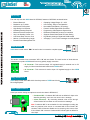
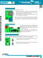
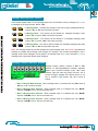
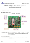
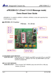
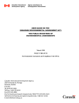
EleSof
®
V01
VRPB
RECORD
V
R
P
B
PLAY
VRPB is 680 Second Audio Record & Palyback
board, offers true solid stage capability and
requires no software or microcontroller support to
record or play back recorded sound
Visit :
www.elesof.com
www.projectsmaker.com
Voice Record & PlayBack System
®
EleSof
Development System
TO OUR VALUED CUSTOMERS
I want to express my thanks to you for being interested in our products & having
®
confidence in EleSof Technologies.
It is our intention to provide you with the best quality products. Furthermore, we will
continue to improve our product performance to better suit your needs.
®
EleSof Technologies
®
The ATMEL name and logo, the ATMEL logo, AVR, AVR (Logo), AVR Freaks, AVR
®
®
Freaks (Logo), AVR Studio, IDIC, megaAVR, megaAVR(Logo), picoPower , tinyAVR
are trademarks of ATMEL®Corporation. All other trademarks mentioned herein are
property of their respective companies and are only used for the purpose of
identification or explanation & to the owner’s benefit, with no intent to infringe.
Visit :
www.elesof.com
www.projectsmaker.com
TABLE OF CONTENTS
Introduction....................................................................4
Specification ...................................................................4
Key Features ...............................................................4-7
Main Chip
Reset Switch
+5V Section
Busy Status LED
Voice Input Section
Voice Output Section
Power Supply Section
Play/Record Selection Section
Message Mode Selector Section
Message Location Selector Section
Getting Started...............................................................8
Interface VRPB with Microcontroller ............................8
Visit :
www.elesof.com
www.projectsmaker.com
e EleSof
®
s
USER
MANUAL
V01
VRPB
4
VRPB SOUND RECODER PLAYBACK SYSTEM
Introduction
VRPB 680 seconds voice record & playback
board design over APR33A3 IC, This VRPB
board offer true solid state storage capability and
requires no software or microcontroller support.
The VRPB board specially designed for simple
key trigger, user can record and playback the
message averagely for 1, 2, 4 or 8 voice
message(s) by switch.
Package contains:
Development system: VRPB Board.
CD: User Manual & supportive documents.
Specification
Power Supply
: 9V-12V AC/DC power supply through power jack or with screw head connector.
Power consumption : 50mA in idle state (when on board module & port are inactive)
Dimension
: 3.9x2.25 inch
PCB
: Glass Epoxy with Green Masking
Key Features
Complete VRPB board is divided into 10 section, which are..
1. Main Chip
2. Reset Switch
3. +5V Section
4. Busy Status LED
5. Voice Input Section
6. Voice Output Section
7. Power Supply Section
8. Play/Record Selection Section
9. Message Mode Selector Section
10. Message Location Selector Section
8
9
10
2
5
6
1
7
4
3
es EleSof
®
USER
MANUAL
V01
VRPB
5
Main Chip
VRPB SOUND RECODER PLAYBACK SYSTEM
The main chip use with VRPB board is APR33A3, features of APR33A3 mentioned below.
External Reset pin.
Resolution up to 16-bits
No External ICs Required
High Quality Line Receiver
No Battery Backup Required
Minimum External Components
Very Low Standby Current: 1uA
Low Power-Down Current: 15uA
680 sec. Voice Recording Length
Powerful Power Management Unit
Operating Voltage Range: 3V ~ 6.5V
User Friendly, Easy to Use Operation
Nonvolatile Flash Memory Technology
Powerful 16-Bits Digital Audio Processor.
Programming & Development Systems Not
Differential-ended MIC pre-amp for Low Noise
Supports Power-Down Mode for Power Saving
High Quality Analog to Digital and PWM module
Averagely 1,2,4 or 8 voice messages record & playback
Reset Switch
VRPB board contain switch “SW1” whose function is to reset the complete system.
+5V Section
This section consists of two connectors “J5” & “J6” with two diodes. The main function of diode with two
connectors is to protect VPRB board from wrong polarity supply connection.
J5 Connector : This connector output +5V regulated supply for external use. ie +5V
supply for Microcontroller board interface with VRPB board.
J6 Connector : This connector is used to input +5V regulated supply to drive VRPB
board.
Busy Status LED
VRPB board contain LED “D8” which show busy status of VRPB board during
Recording/Playback
Voice Input Section
Voice input section having two options to record voice data in APR33A3 IC,
Condenser MIC : Condenser MIC will work as default for input voice
data & by speaking over it one can record voice message.
3.5mm Connector : By connecting external voice source through
3.5mm female “J4” connector we can record voice message.
Note: Condenser MIC is set as default for voice message recording but
when any external voice source is connected with 3.5mm female “J4”
connector, MIC will become disable and on removing voice source from
3.5mm female “J4” connector Condenser MIC will set again as default for
voice input.
e EleSof
s
®
USER
MANUAL
V01
VRPB
6
Voice Output Section
Voice output section having two connectors for voice data out.
VRPB SOUND RECODER PLAYBACK SYSTEM
Screw Head Connector : Through this Screw Head connector
“LS1”, an amplifier or small speaker can connect to play recorded
voice message. Note: Speaker should be of 8 ohm.
3.5mm Connector : Though this 3.5mm female “J1” connector, user
can connect booster or home theater.
Note: In this section Screw Head “LS1”connector is set as default for
voice data output, on connecting any Audio playing device through
3.5mm female “J1” connector “LS1” connector will become disable.
Power Supply Section
The VRPB board has on-board +5V regulated power
supply with Power jack “Con2”, Screw head connector
”Con1”, Bridge rectifiers, 7805 regulator, Filter circuit &
Power indicator LED “D3”.
This board supports both DC & AC adaptor and if
adapter is not available than user can use 9V to 12V
500mA transformer as power source.
Play/Record Selection Section
Play/Record selection consist of two LED’s “D6” “D7” & one push switch “J2”. Here the main role is of “J2”
connector for selection of Play back recorded message or for recording new voice message.
J2 Pressed : When “J2” switch is pressed LED “D7” will light up &
VRPB system will enter in recording mode.
J2 Released : When “J2” switch is released LED “D6” will light up &
VRPB system will enter in playing mode.
e EleSof
s
®
V01
VRPB
USER
MANUAL
7
Message Mode Selector Section
VRPB SOUND RECODER PLAYBACK SYSTEM
VRPB system support fixed 1/ 2/ 4/ 8 message mode; user can divide the memory averagely for 1, 2, 4 or
8 messages by the help of jumper “JP1” & “JP2”.
J1
J2
J1
J2
J1
J2
J1
J2
1-Message Mode : Complete chip memory will be use for signle message when both
jumpers “JP1” & “JP2” are close after chip reset.
2-Message Mode : The memory will be divided to 2 messages averagely when
jumper “JP1” is open & “JP2” is close after chip reset.
4-Message Mode : The memory will be divided to 4 messages averagely when
jumper “JP1” is close & “JP2” is open after chip reset.
8-Message Mode : The memory will be divided to 8 messages averagely when both
jumpers “JP1” & “JP2” are open after chip reset.
Note: The message should be recorded and played in same message mode; we CAN NOT guarantee the
message is complete after message mode changed. For example, user recorded 8 messages in the 8message mode; those messages can be played in 8-message mode only. If user changed to 1, 2 or 4
message mode, system will discard those messages.
Message Location Selector Section
Message location selector consists of “M0” to “M7”
switches for Recording/Playback message segments
depend upon selected message mode. With these
switches, eight pin male berg strips connector “J3” is
present to trigger message from external device or can
say to interface VRPB system with other circuits &
boards.
When 1-Message Mode Selected : When message mode 1 is selected than only “M0” switch &
“M0” pin of “J3” connector will work.
When 2-Message Mode Selected : When message mode 2 is selected than only “M0-M1”
switches & “M0-M1” pins of “J3” connector will work.
When 4-Message Mode Selected : When message mode 4 is selected than only “M0-M3”
switches & “M0-M3” pins of “J3” connector will work.
When 8-Message Mode Selected : When message mode 8 is selected than only “M0-M7”
switches & “M0-M7” pins of “J3” connector will work.
e EleSof
s
®
USER
MANUAL
V01
VRPB
8
Getting Started
Connect Speaker with “LS1” connector or any amplifier system though 3.5mm female “J1”
connector.
Select Message mode 1/2/4/8 through jumper “JP1” & “JP2”.
VRPB SOUND RECODER PLAYBACK SYSTEM
Press “J2” connector to set VRPB system in recording mode, “D7” LED will light up.
Power ON VRPB system.
Let us assume message mode 8 was selected above. This will give us 8 messages of
approximately 85 seconds each message.
Now when any switch (M0, M1, M2 3 M7) pressed in record mode, the VRPB system will first
playback “beep” tone and message recording started. Message recording will continue until
pressed message switch not released or message memory not full, as recording finish VRPB
system will playback “beep” tone 2 times to indicate the message record finished.
Note: If the message already exists and user record again, the old one’s message will be
replaced.
Now for playing recorded message keep message mode (1/2/4/8) same which is set at the time of
recording.
Release “J2” connector to set VRPB system in play mode, “D6” LED will light up.
Now press any switch (M0, M1, M2 3 M7) to play recorded message over particular location, and
message will playback until the user pressed the tact-switch again or message got finish.
Note: If message play is interrupted by pressing any switch (M0, M1, M2 3 M7) or by
external trigger (0 low) on pins of “J3” connector, current message will stop and new
message will start to play.
During message play/recording “D8”
D8 LED will light up, which indicate busy status of VRPB
system.
Interface External Trigger to Microcontroller
Below schematic is showing how to interface External Trigger
Points with Microcontroller.
Micro Controller
+5V
Note: GND of VRPB system & Microcontroller board should be common.
M0
M1
M2
M3
M4
M5
M6
M7
J3
M0
M1
M2
M3
M4
M5
M6
M7
®
EleSof
Development System
DISCLAIMER
This product is owned by the EleSof are protected by copyright law. Therefore, this
manual is to be treated as any other copyright material. No part of this manual,
including product & software described herein, may be reproduces, store in a retrieval
system, translated or transmitted in any form or by any means, without the prior written
permission of EleSof. The manual PDF edition can be printed for private or local use,
but not for distribution. Any modification of this manual is prohibited.
EleSof provides this manual ‘as is’ without warranty of any kind, either expressed or
implied, including , but not limited to, the implied warranties or condition of
merchantability or fitness for a particular purpose.
Elesof shall assume no responsibility or liability for any errors, omissions &
inaccuracies that may appear in this manual. In no event shall EleSof, its directors,
officers, employees or distributors be liable for any indirect, specific, incidental or
consequential damages (including damages for loss of business profits & business
information, business interruption or any other pecuniary loss) arising out of the use of
this manual or product, even if EleSof has been advised of the possibility of such
damages. EleSof reserves the right to change information contained in this manual at
any time without prior notice, if necessary.
All the product, tools & corporate names appearing in this kit & manual may or may not
registered trademarks or copyright of their respective company, & are only used to
identification or explanation & to the owners’ benefit, with no intent to infringe.
Visit :
www.elesof.com
www.projectsmaker.com
®
EleSof
Development System
If you want to learn more about our products, please visit our website at
www.elesof.com & www.projectsmaker.com
If you have any questions, comments or business proposals, do not hesitate to contact
us.
If you are experiencing some problems with any of our products or just need additional
information, please place write mail or call to us at
[email protected] & [email protected]
+91-9911-7095-92 & +91-9044-1359-01
Visit :
www.elesof.com
www.projectsmaker.com
®
EleSof
Development System
HIGH RISK ACTIVITIES
The products of EleSof are not fault - tolerant nor designed, manufactured or intended
for use or resale as on – line control equipment in hazardous environments requiring fail
– safe performance, such as in the operation of nuclear facilities, aircraft navigation or
communication system, air traffic control, direct life support machines or weapons
system in which the failure of software could lead directly to death, personal injury or
severe physical or environment damage (‘High Risk Activities). EleSof & its suppliers
specifically disclaim any expressed or implied warranty of fitness for High Risk
Activities.
®
Copyright 2010 – 2012 by EleSof Technologies. All .right reserved
Visit :
www.elesof.com
www.projectsmaker.com