1
CR-189382
Final
Report
for work
performed
under
/
USRA
Contract
towards
MCIDAS-EXPLORER
the development
A
PLANETARY
/t/
No. 5555-08
VERSION
_-"
"/L_
of
OF
3,1CIDAS
FOR
APPLICATIONS
Sanjay
Principal
S. Limaye
Investigator
Co-Investigators:
R. Stephen Saunders (JPL)
Lawrence
A. Sromovsky
(SSEC)
Michael Martin (JPL)
ee_
¢xl
o,
Z
_
_)
O
0
N
aO
O
@t
_.. _.
OI-,--t.U
Q-Z
Space Science and Engineering
Center
University
of Wisconsin-Madison
1225 West Dayton Street
Madison,
Wisconsin
53706
_...J
I _tn
..J
0.
L
O
O_
QO
,.._ t.L
af
_J
(608)262-9541
sanjayl@ssec,
wisc.edu
Q
tN
O'U.
_O
Z
O
I Z
_0
L.) 0.-d
I ¢_
July
1994
VIUJ
Z
..J
o. _0
f_
"M
APPENDIX
I
Abstracts of presentations
at the Division of Planetary
Science Meetings
in 1993 and 1994,
the Lunar and Planetary
Science Meeting,
1994, and the Planetary
Data Visualization
Workshop
in 1993.
at
SUM3,IARY
This is the final report on the developmentof MclDAS-eXplorer,
an extension
MclDAS
for solar system applications.
This work has been supported
under the Applied
formation
Systems Research
Program
funded by NASA under USRA contracts
5555-08
S.C. 550-08, and NASA Contract NAS5-31347.
The
by the
satellite
initial goals
of this effort
were
to bring
to the planetary
community
the tools
of
Inand
used
terrestrial
meteorological
community
for the access, display
and analysis
of weather
data.
An additional
consideration
of the use of UNIX workstations
and PC's as soft-
ware platforms.
The primary target data for this endeavor
are the imaging data from NASA's
solar system
missions
are the CD-ROM
volumes
pub!ished
by the Planetary
Data System
(PDS).
Another
goal of the proposed
effort was the facilitation
of a graphical
user interface
for user interaction.
These
goals have been met.
MclDAS-eXplorer
allows
the user to access the full
calibration
and navigation
data attached
in the PDS labels.
The data can be manipulated,
displayed,
animated using the developed
tools.
The user manual and help are accessible
online from within an eXplorer
session.
These capabilities
have been achieved
in the last three
years by the development
of over 160,000
lines of code (mostly FORTRAN
and C). These
are based on about 150,000 lines of "core" MclDAS-X
:5"_dMclDAS-OS2
versions.
MclDASeXplorer
is now able to access the PDS solar system data, including
the attached
navigation
and calibration
information.
For images that do not have the SPICE kernels attached,
new
image navigation
tools based on the NAIF SPICE toolkit have been incorporated
within the
eXplorer
suite.
To expose the planetary
community
to the capabilities,
MclDAS-eXpiorer
has been
demonstrated
at Division of Planetary
Sciences
Meeting in Boulder (October
1993), and at the
25th Lunar
and Planetary
Sciences
Meeting
in Houston
in March
1994.
It is also being
demonstrated
at the 26th Meeting of the Division of Planetary
Sciences
Meeting
in November
1994 at Washington
D.C. (Limaye et al., 1994).
MclDAS-eXplorer
has been demonstrated
at
the AISRP Workshops
in Boulder in 1992 and 1993.
The eXplorer
binaries
for AIX, IRIX,
HP-OS
and SunOS
and OS/2
2.1 operating
systems
can be obtained from the Space Science and Engineer Center.
It is likelv that the Software
Support
Laborato_'
at University
of Colorado,
Boulder will also be an avenue for access to MclDASeXplorer.
This final report describes
the eXplorer sol, rare capabilities
and includes a printed
cop3' of the User Guide
ray _mpact parameter,
both of which are directly obtainable from the
Jreauencw data ar_ tralectory trdormatLon (F]elcLbo. Kiiore. and Esrtleman
1971. ASTRON. J. 76. 123-140.)
OccuilalJon studies of the giant planets r_ave clernonstratecl that 0epartures
1ram sphencal symmetry. _ not accounted tot. can result in serous errors
(Eshleman 1975, SCIENCE
18S, 876-878,) In the present stuOy, we t_ave
analyzed and quantdied errors in temperature
anti pressure profiles clue to
large scale atmospheric
'tilts' in an otherwise sphencal atmosprmre,
inciuclmg the role ot occultation geometry in enP.m'cmg or suppressing trois
error.
The effect of atmospheno tilt is to introduce an approximately constant bias
in the lemperalure profile. For example, a horizontal tilt ot 0.6 mrad in the
Martian atmosphere can bias temperature profiles by up to 0.3 KeN'ins.
clepencling on It_e occultation geometry ancl on the onentat=on of the tilt. A
much more severe slope of 4.8 mrad. whicl_ migM exist in the upper
atmosphere at the bounclary of the polar caps (PoliacX el. aJ. 1990. J.
GEOPHYS,
RES., 95, 1447-1473)
ancl where most occuRations of Mars
Observer are expected to occur, could bias the temperature profiles by up to
3.2 Kelvins for an orbit opening of 30 degrees,
rf sucre effects were
neglec'led.
Our approact_ in modeling the tJ_ has been to assume the local atmosphere
to be spnereally symmemc but with a clifferent center of symmetry. This
&oproacn is satisfaclory for the case in whP,;_ the ray psnaDs_s OdeS not vary
too muct_ in latitude and Iongltucle dunng the course o1 an oc_ultat|on,
Results from the NASA-Ames
GCM for Mars suggest tidal honzomal
vanatpons m pressure are mucr_ more severe across latltuOe ttlan mey are
across longltucle. An axially symmetno figure of revolution should be a Defter
model for t_e straps of the Martian polar atmospt_ere trtan ts a large scale
tilt.
The currern aoproact_ incorOorates errors clue to imprecuse knowledge aJ_oul
It, e Ideation o1 tt_e transmrner, lhe recmver ancl the center o_ tP.e occulting
planet, ar'_ is not resmcted to any specltic occultabon geometry.
Session
13: Invited
C. Pieters,
Talk
Moderator
2:20-3:00
pro, Grand
Ballroom
13.01-INV
Breakthrough=
of Planetz
C.
de
in
Bergh
ResEnt
Ground-Baaed
(Ohservatoir_
progress
in
Spectroscopy
de P=u'is)
in£rared
tation
and
the development
dited
the
study
detector
technology
and
instrumen-
o_ ialrared axrays h-re strongly ben-
of pLanet_ 7
ground-bar, ed spectroecopy.
these studies. Three
Tnfrared
etmoapheres
We
important
and
suri'aces using
will review
the most
brta.ktkrougks
will be
recent of
more
par-
ticularly diacu.saed:
1) the nEW
aludy
of the deep atmozphert
of Venus
by mEMuring
neax-infraxtd radiation of the dark _ide of the pia.net,
2)
the
momtoring
Jupiter
uaing
3) the
detection
of
processes
Fr_"inS.r_ed
in
occurring
the
ionospher_
of
emissions,
of nitrogen
ice
_t the
surf_e
of Pluto.
11.15-P
MciDAS-eXplorer:
S.S.
Limaye.
(Spa::
(JPL
Sci.
A Vehicle
L.A.
Sromovsky,
& Eng.
Ctr, Univ.
for Analysis
of Solzr
R. Krauss,
E. Wright.
of Wisconsin-Madison)
SystEm
Data
D, Santek.
and R.S.
P. Fry
Saundert
Poster
Presentation
Posters
MclDAS-cXplorer
is a software environment berne develop_ to provide
acc,'_s to and Enable efficient analysis of goophyslc_l data acquired about
solar system objects.
It is an enhancement of Mc]DAS-X
(a too]kit
direct_
at the terrestrial memorological
community for analysis of rtaitime weather satellite, conventiontd and foroca._t modal output. MclDASeXplorer
CD-ROM
provides
access to and enables inv,-tugauoo
of data from the
volumes published by t_e Planetary Data Sysmm from NASA's
solar system rmssions and incorporat_ the SPICE subroutine librar'y
developed
by the Navigation
and Ancilla.,'y laformation
Fa_ilit,/ (NAIF)
at the Jet Propulsion
Laboratory
for _e dtsptay,
tavigation,
ammauon
and _alvsis of planetary data on most UNIX
work.s_dons with Xwindows'support. Prim_ily inmnded for analysisof image data. the user
extensibleenvironment provided by McLDAS-eXplorer allows analysisof
a wide variety, of data with rmnitr_ EffOrt it_ a mu[dfra.me (with overlay
graphics),multitasking
environment.
Currently,
tools are avzaJable for
c_ibntion,
navigation
add an_ysis
of Voyager
imMcs of the giant
planeu a_d their samllitcs.
Magellan
radar az=:l altimeter
data. Viking
OrbitEr,
Mars Mosaicked
Digital Image Model dam, and Galileo images.
Tools are being added for access to and analysis
of a_'nosphertc
profi]_
u well as spectraldata such as Marines-9
IRIS and Voyager
IRIS
observed nt .
This work is funded by Contract# NA55-31347
Inform_uon Systems Research Program.
from NASA's
Applied
from
3:00-3:30
_
/ q q J.,
p.
/ o g T,
14: Comets
12:1992
Urey
Prize
Lecture
and
3:30--5:30
pro, South
Moderator
1:30-2".20
pro, Grand
No,
We
The
flux
vary
a.s a result
of
to
1981).
in the
Oort
system
is
addition,
past
past
cloud,
On the
Diversity
of Plausible
Planetary.
Systems
J. Lissauer
Using
are
with
empmyed.
the
be
expected
for
allow
the
1/a,
would
maior
invoked
estimated
that
will
one
to set
perturbations
the
Earth
for
that
shower
for
of
an upper
the
limit
Oort
predicted
highly
non-
long-period
Oort
on the
orbital
the
Taken
cloud.
the
over
different
long-period
shower.
In
the
models,
are
inner
solar
Two
of the
the
the
Moon
comet
shower.
86,
over
the
simulation
distributions
cometary
on
explain
it is shown
distribution
the
to try and
of long-period
a perturbation
a major
not
flux.
for
a cometary
random
or
estimated
a cometary
J.
of comets
cometary
dynamical
First,
from
with
of
tests
been
Astron.
population
enhanced
distributions
distributions
evidence
two
whether
know
computer-based
inconsister.;
in contrast
recent
region
perturbations
G.,
to
twice
current
J.
the
currently
is about
(Hills,
an
have
rate
no
these
planetary
of external
estimate
experiencing
showers
Second,
the
rate
system
it is necessary
the
tests
element
and
to correctly
shows
any
Jack
planetary
which
that
are
comets.
Lecture
the
currently
3 Gyr.
through
magmtude
In order
Myr,
Laboratory)
In extreme
cases, star passages
through
the Oon
with GMC's
can cause
showers
of 10' or more
cratering
250
Shower
comets
of the
cometary
random,
Prize
long-period
enter
1730,
orbit
C. Urey
Ballroom
(Jet Propulsion
on the Oon
cloud.
cloud
or encounters
dynamical
Harold
Moderators
in a Cometary
Paul R. Weissman
elements
12.01-INV
Not
Are
it is shown
Ballroom
J. Crovisier,
14.01
the
(2. Pieters,
Ill
S. Hoban
cn.banced
Session
14-15
pm
Session
comets
v'.r_.
Sessions
comets
cloud,
magnitude
This
at
together,
work
of
was
ql
MI_j_
_LI
xr
INTRODUCTION
This is the final report for work performed
for the development
of MclDAS-eXplorer,
a version of MclDAS
for planetary
applications
under USRA/CESDIS
contract
No. 5555-08
for the period July 15, 1994 - July 14, 1994.
USRA is supported
by NASA under contract
#
NAS5-32337.
Prior work under the effort has been described
in progress
reports
under
USRA/CESDIS
Contract
550-80
and NASA/GSFC
Contract
NAS5-31347
for the preceding
two years respectively.
A Mc_,DAS-eXplorer
User Guide has been produced
that is the
culmination
of the work perform_
under NASA support and is attached to this report.
This
User Guide is intended as a companion
volume to the MclDAS-X
and MclDAS-OS/2
Guides.
The third and final year of MclDAS-eXplorer
development
has concentrated
on porting
eXplorer
code to different operating
systems, streamlimng
the installation
procedure,
identifi,fing
the operating
system and version specific items, implementing
sotb, vare revision control for the
source code and adding support for some remaining
Planetary
Data System data products.
The
progress
in the last quarter is described
below.
To provide a comprehensive
overview, the capabilities of the MclDAS-eXplorer
soi_vare are also summarized
below.
MclDAS-eXplorer
User
Guide
is attached
in Appendix
I.
MclDAS-eXplorer
Overview
MclDAS
eXplorer consists of FORTRAN
and C routines that conform to the MclDAS
environment
in terms of data structures,
user interfacc, data navigation
and calibration
implementation.
For reasons of portability, and sot_vare maintenance,
the new code developed strives to
adhere to the modem
programming
practices
which have been amply described
in Fortran
Programming
Standards
and Guidelines'
(JPL D-6613) and also to the standards
followed bv
the NAIF toolkit.
MclDAS and eXplorer applications
to accomplish
specific tasks are developed
as modules that are callable from a control program.
A module that would be traditionally
a
"main" program is a "key-in" within the MclDAS environment.
The size statistics are as follows.
MclDAS-X
eXplorer
NAIF-Spice
library, modules:
library modules:
library modules:
939 (Core MclDAS core)
1291 (This effort)
515 (developed at JPL)
Lines of code:
MclDAS-X:
NAIF
For comparion,
Number
eXplorer:
library:
eXplorer:
Space
(Core, Versmn 2.0)
(New code. thios effort)
(Developed at JPL)
of Keyins:
Core MclDAS-X:
Total
148,761
161,872
138,570
eXplorer
required
object library
for binaries
size is about
(both MclDAS-X
IRIX 4.5:
IRIX 5.2:
AIX3.2.5:
HP-UX 9.03:
119 (including
single letter commands)
82 (New)
9 Mbytes.
and Explorer):
200 Mbytes
10 Mbytes (shared
130 Mb3¢es
230 Mbytes
object
library,
requires
larger
swap space)
* Produced by the Telecomminucations
and Data Acquisition Office and the Space Flight Operations
Center, Jet Propulsion Laboratory, Pasadena, California, September 1989 (TDS Document No. 890-218,
SFOC Document SFOC0095-00-01).
The operability
of MclDAS-eXptorer
on different
platforms
has been a goal of this
project
from the beginning.
Besides
the SGI and IBM RS-6000
workstations,
the core
MclDAS-X
software
has been ported to HP and Sun workstations
(SunOS 4.1.3, SunOS 5.3,
and Solaris 2.3) and and hence the explorer
portion can also be used on those workstations.
The port to the UNIX on a PC platform,
UNIXWARE
from UNIVEL
was a disappointment
in
terms of operating
system peculiarities
and support of graphics
cards.
The effort required to
support
this particular
operating
system has been considerable
and is now deemed to be
unaffordable,
at least in the short run, until either the operating
system itself matures and more
support
is available
from the vendor.
We have briefly looked into the use of an alternate
UNIX implementation
on a PC platform,
the LINUX operating
system which is in the public
domain.
Some portions of the PC-MclDAS
have been ported, but once again the support of
high end graphics cards is minimal and it is not known whether the eXplorer software could be
effortless
ported.
For lack of sufficient resources,
the work has on porting the software to the
UNIX on Intel chip based machines
ihas been at least temporarily
halted, pending
future
support.
MclDAS
and
MclDAS-eXplorer
can
be
used
under
the
IBM
OS/2
Version
2.1
operating
system except for the GUI available
on X-window
platforms.
Previously
running
MclDAS under OS/2 required the use of a special video display card which was available only
for the microchannel
bus. We supported
the development
of the Presentation
Manager for the
graphical
display environment
under OS 2/2.1.
Thus any high end graphics
card that has
drivers for OS/2 2.1 can be used for running MclDAS
on any bus-microchannel,
ISA, EISA or
the local bus variants,
VL and PCI.
HIGHLIGHTS
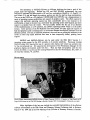
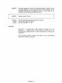
Nicolle Zellner demonstrating MclDAS-eXplorer
Rages (NASA/Ames)
at the 25th DPS Meeting
to Nancy Chanover (NMSU),
in Boulder, October 1993. Co-Investigator
Major highlights
of this last year include the successful
software
environment
at the 25th Lunar and Planetary
Science
March
14-18,
1994
A. Sanchez La Vega (Spain) and K.
and at the 25th Meeting
of the Division
L. Sromovsky is at right.
demonstration
of the eXplorer
Conference
held in Houston,
of Planetary
Sciences
in Boulder,
Colorado
during
submitted
for the DPS
anticipated
November
meeting
that a workstation
We demonstrated
at both
Lunar
the meetings.
and Planetary
duration
of the
1993.
to be held
meeting.
published
in the NASA
Information
capabilities
adjacent
Previously
Colorado
during
1994
eXplorer
software
in Washington
has
D.C.
been
where
it is
will also be held.
the workstation
Institute
describing
in November
demonstration
At LPSC
in Boulder,
abstract
MclDAS-eXplorer
Science
Workshop
An
which
on a Silicon
was
to the Johnson
MclDAS-eXplorer
August,
Systems
1993.
Newsletter
Indigo
set up
in the
exhibit
Space
Center
in Houston
was
An
Graphics
demonstrated
article
(February,
describing
Extreme
area
at the
eXplorer
at the
for the •
AISRP
was
1994)
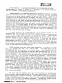
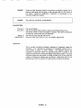
MclDAS-eXplorer being demonstrated to Jim Dodge of NASA's Office of Mission to Planet Earth at the AISRP
Workshop held in Boulder, August 3-6, 1993 by Sanjay Limaye (PI). Onlookers include Bob Krauss and David
Santek of SSEC (left and front center) who participated in the explorer development. (Photograph by Sandy Dueck,
J'PL)
David Santek explains eXplorer capabilities at the
LPSC conference in Houston using the poster display
set-up adjacent to the workstation in the exhibit area
at LPI
Co-lnvestigator
Steve Saunders looks on while
eXplorer capabilities for Magellan data are
demonstrated on the SGI workstation at the LPSC
conference
(above).
McIDAS-eXplorer
at the 25th LPSC
Meeting
Copies of the abstracts of papers describing
MclDAS-eXplorer
are attached in Appendix
I. A
copy of the article that describes
MclDAS-eXplorer
is attached in Appendix
II. Finally,
the
final version
of the MclDAS--eXplorer
User Manual
is attached
separately
as part of this
report.
Acknowledgements
Many individuals
contirbuted
to the development
of MclDAS-eXplorer.
Mr. Robert
Krauss, Mr. Edward Wright wrote a significant
amount of code. System support was provided
by Mr. Patrick
Fry and Mr. Steven rader.
Mr. David Samek and Ms. Sue Gorski assisted
with core MclDAS-X
system related issues.
Mr. Ken Bywaters,
Mr. Russel Dengel and Mr.
Gerry
Peltzer
developed
several
new applications.
Much needed other support
was also
provided by the Space Science and Engineering
Center.
Planetary
Data
Visualization Workshop
Report of a workshop sponsored by
NASA's Solar System Exploration
Division and held at
San Juan Capistrano Research Institute Nov. 15-17, 1993
SJI
Prepared by Doug Nash
San Juan Capistrano
Research Institute
San Juan Capiswano, California
April 26, 1994
SJI TECH. REPORT
94-1
mlII NAL
-
MCIDAS-EXPLORER
SYSTEM
and
DATA;
R.S.
S.S.
Saunders,
Jet
by
of
to
extensible
been
solar
the
developed
of
to
by
the
currently
exists
system,
McIDAS-OS2
Mc!DAS-X
both
for
the
X
A
0S/2
prime
Planetary
now
Data
Orbiters
Voyager
Orbiter
1
still
except
in
Mercury
systems
and
the
of
and
and
distinguished
from
byte)
and
location
system
data
vector
the
nearly
60
volumes
gigabytes
and
McIDAS
most
block
containing
illustrated
the
by
numerical
Files.
Each
Grid
a
File
Directory
Grid
file.
grids
'Simple
from
The
surface
spectra
stored
a
simple
database
PI_
third
acquired
as
can
arithmetic
that
many
the
weather
2.
It
mainframe
ccmputers,
is
as
and
compatible
with
access
to
the
published
by
the
to
These
the
comprise
on
CD-ROM
Viking
Venus
i
2
the
Galileo
all
the
planets
a
these
and
and
satellites
provides
and
common
ring
approach
different
categories-
the
targets
in
contain
multiple
grids
access
data
and
may
of
the
an
data
type
is
data
form
or
of
Grid
quantities,
the
are
into
data
the
by
CD-ROM
with
field
different
operations
solar
I00
imported
second
for
8-
have
the
nearly
in
or
illustrated
gravity
McIDAS
are
geographical
Areas'
The
roadmap
'spread-sheet'
(4
For
are
contents.
within
the
data
topography,
stored
real
form
'Digital
be
data
single
on
image
can
be
necessary.
contained
called
the
image
a
or
data
gridded
may
prevalent
These
files
is
as
images
of
the
most
tools.
in
values
generally
graphic
image
The
data
than
the
system
The
depth.
are
is
(i)
data.
components
type
and
or
for
planetary
data
smaller
provides
contents
and
of
possible
with
the
the
McIDAS.
and
the
simplest
station
for
file
search
and
PJk_.
u.._.le_
data
observations
a
specific
Meteorological
flat
in
resolution
data
File
within
weather
as
data
spatial
the
2-byte
data
stored
output
of
data
or
particulars
low
model
1
solar
and
the
output
Survey.
data
station
McIDAS-eXplorer
environment
by
provide
such
mission
the
three
(iii)
station
of
has
University
interactive
model
volumes
Geological
many
of
data
with
user
navigation.
for
first
to
missions
These
dimensions
The
the
personal
CD-ROM
McIDAS-eXplorer
and
have
US
Radar
display
image
an
McIDAS
integrated
version
is
200
by
as
either
the
targets,
the
and
have
elements.
and
well
and
of
McIDAS-MVS
for
as
is
UNIX.
collected
system
Jupiter.
tools
generally
missing
as
data
multispectral
nearly
asteroids.
manipulation
gridded
on
Magellan
to
Pluto
two
provides
(ii)
2,
analysis
data
McIDAS
data
and
Built
McIDAS.
collected
transit
soon,
access,
terms
data
an
explorer
capable
collected
environment
of
numerical
versions-
a
data
1.
Center
to
McIDAS-eXplorer
(PDS)
image
as
The
earth
explorer
output
well
provide
the
flavors
providing
operating
of
of
the
model
as
0S/2
available
System
contain
on
workstations.
versions
SOLAR
Wisconsin-M_dison,
to
the
Engineering
and
different
objective
data
volumes
data
as
different
focus
means,
the
UNIX
well
and
primary
three
for
the
and
planetary
to
in
OF
of
visualizing
McIDAS,
many
Science
conventional
U.
designed
and
as
of
on
meteorological
and
enviror__ent
targets
Space
VISUALIZATION
Sromovsky,
displaying
version
implemented
with
the
satellites
software
is
FOR
L.A.
Laboratory.
system
Wisconsin-Madison
access
a
X-windows
and
ENV_RONM_NT
Santek,
analyzing,
to
extension
D.
is
accessing,
missions
SOFTWARE
Propulsion
McIDAS-eXplorer
means
A
Limaye,
II
Data
with
a
location.
('MD')
directory
retrieval,
ROT
type
or
FtL.M[_
as
well
is
for
These
files
with
structure.
as
illustrated
solar
data
system
types
data
of
tagged
The
editing
on
the
targets
MD
data
by
file
functions.
Earth
by
are
by
infrared
optionally
keywords
format
or
allows
as
i _
'_
: _ _,_ _
-_
_
_
a_¢.._Nl_
_"
MCIDAS-EX_LORZ_:
These
ways,
different
either
view,
animation
helps
atmospheric
with
independent
oriented
parameters.
The
up
a
task
string
entering
a
through
name
with
the
explicitly.
Then
of
values
range
and
executed
batch
more
in
explicit
a
A
FORTRAN
execute
that
McIDAS
is
McIDAS
end
limited
workstations
ported
video
via
in
is
that
in
as
is
well
used
the
replaceable
can
record
the
sequence
issuing
a
the
macro
control
and
command
keyword
is
to
set
parameters
sequence
for
parameters.
of
that
Mc!DAS
A
commands
command
command
a
repetitively
that
replaceable
can
as
method
execute
the
is
GUI
Experienced
through
that
User
and
the
itself.
directly
with
for
flow
sense
used
then
the
of
frames
ring
an
and
and
to
to
execute
can
accept
commands
for
capable
It
the
x
the
data.
be
the
both
and
of
being
has
been
of
a
with
A
board
the
sessions
then
and
PC
low
running
concurrent
satisfactory
either
on
network
end
we
A
a
for
same
of
recently
local
bus
operating
supported,
workstation
a
high
number
have
UNIXWARE
users
run
the
a
with
the
UNIX
can
mode.
equipped
number
typical
color
to
the
based
the
memory
full
possible
At
MHz
drive
number
in
McIDAS
even
platforms
video
1024
is
DX2/66
CD-ROM
all
resources.
capable
multiple
486
a
a
1024
share
Intel
on
available
and
of
support
card
Except
workstation
data
tasks
first
compile
X-terminals.
a
to
display
system.
16
can
McIDAS
and
by
Mbytes
with
or
of
animated
Graphical
The
command
to
A
parameters,
environment
only
32
workstation
workstation
is
multiprocessing
with
session
lapse
means
command.
a
processes
workstation
time
a
specific
process
commands
be
single
for
and
the
original
methods.
specified
statements
macro
to
to
the
means.
the
system
of
is
that
controlled
for
the
the
different
file
means
so
to
of
in
uedesign
sequence
a
text
third
variety
positional
method
"batch"
file.
standard
of
parameter
access
a
looping
provides
user
customized
both
commands
_he
of
of
"in
Typically
domain
&_ructure
with
three
identified
second
C
of
a
be
to
accept
cases,
McIDAS
full
program
having
all
variety
image
navigation.
can
interact
time
a
3-D
immensely.
sequence
through
that
underlying
simplified
and
McIDAS
commands
a
providing
units
to
the
in
pseudo
In
analysis.
in
frame
usually
McIDAS
any
data
a
respects
Sauriders
visualized
as
display.
in
of
and
be
image,
variable
lapse
prefer
generally
many
aspect
with
without
window.
be
in
available
the
can
Sromovsky
stereoscopic
quite
key
is
usually
can
a
component
of
changed
types
uncalibrated
(GUI)
San_e_,
dimensional
user
interact
Interface
users
even
time
each
or
Users
or
a
such
calibrated
two
is
are
displaying
a
the
data
observations
be
data
as
perspective
loops
Limaye,
such
the
a
individual
scientist.
McIDAS-eXplorer
Information
1
Limaye,
and
Systems
S.S.,
R.S.
Science
developed
under
support
from
NASA's
Applied
Branch.
L.A.
Sromovsky,
R.
Saunders:
A
Vehicle
Krauss,
for
a
Information
Newsletter,
Systems
E.
Wright,
Analysis
of
D.
Solar
Issue
Santek,
System
30,
October
S.
Gorski,
Dara,
NASA
1993,
in
press.
2
Suomi,
V.E.,
R.J.
Interactive
Mereor.,
Data
22,
Fox,
Access
766-778.
S.S.
Limaye,
and
Analysis
and
System:
W.L.
Smith,
McIDAS
III:
1983:
J.
A
Clim.
Modern
Appl.
j_
_
_l_
i_
_
_ ....
_,_Ik_
_
Access,
Abstract
for
25th
LPSC,
Analysis
and
Display
of
R.S.
The
tge
compilation
Magellan
radar
mission
reflectivity
the
on
and
80
the
compisites
analysis
used
extensions
which
recognizable
data
most
UNIX
extensible
are
multi-frame
a
display
processing
and
memory
and
as
as
command
a
is
specific
A
order
animation
McIDAS-eXplorer
data
and
history
stored
label).
to
The
such
cursor)
in
be
retrieved
These
conference.
the
kept
for
the
image
was
data
that
a
displayed
at
the
capabilities
navigation,
calibration
numbers
while
the
tagged
into
roaming
image,
cursor
radar
(with
the
full
quick
are
navigation
format.
along
(e.g.
the
information
use
of
or
calibrated
the
of
and
first
imported
and
calibration
or
the
is
the
the
entire
VICAR
radar
images
accessible
mouse
and
display
Processing
for
a
is
interfaces
with
PDS
reflectivity
as
processing
calibration,
data
run
creation
imported
the
can
user
specific
with
image
computing,
interface
repititively.
a
and
and
different
user
used
in
run
user
interface,
most
the
Batch
are
image
to
is
filters,
availble.
the
the
composites.
allows
each
for
under
available
in
of
line
tools
facility
all
for
Designed
environment
McIDAS-eXplorer,
with
targets
environment
color
use
that
the
applications
practical
or
system
and
available
command
and
graphical
workstation
are
supplementary
raw
system,
of
in
that
convert
exploit
along
records
label
that
fully
capabilities
into
a
mature
enhancements,
create
macro
sequences
to
to
tem_iate,
simvle
a
overlays,
resources
facilitate
calibration
the
and
as
slope
environment.
multi-processing
ability
key
command
In
text
the
are
developed
digital
sessions
storage
function
window.
a
user
peripheral
supported
such
or
as
a
and
capability
graphical
is
applications
end-user
Interface
Planetary
CD-ROM
environment,
system
data
the
the
15
To
on
solar
of
along
observations
X-windows,
animation
such
McIDAS-eXplorer
many
most
of
from
on
surface
based
from
bytes
profiles
software
registration
part
giga
volumes.
satellite
of
surface
70
and
a
is
Venus
data
telescopic
of
projections,
over
CD-ROM
It
based
User
McIDAS-eXplorer
available
data,
supporting
applications
cartographic
these
integral
1994
altimetry
are
2
weather
addition
the
altimetry
of
analysis
Graphical
with
in
radiometry
set
Navigation,
an
14-18,
of
and
data
the
developed.
workstations
both
images
of
ground
allowing
includes
a
earth
allow
and
formats.
planetary
on
been
actually
resulted
imagery
on
for
spacecraft
observations
display
has
Data
topography,
and
extensively
Magellan
been
volumes,
available
McIDAS-eXplorer
is
The
CD-ROM
March
Saunders
radiometry
global
are
access,
has
track.
System
volumes
radar
and
spacecraft
Data
of
data
Houston,
to
navigated
data
location.
will
be
demonstrated
on
Magellan
the
controlleG
data
at
the
can
APPENDIX
Copy of an article
published
II
in the February
1994 issue of the Science
Newsletter
Information
Systems
S
C
I
E
N
C
E
INFORMATION
SYSTEMS
N E W S L E T T E R
FEATURES
NIIT Testbed
1
Envision
3
NCSA PATHFINDER
7
The Earth Data System and
the National Information
Infrastructure
Testbed
Carol A. Christian,
MclDAS-eXplorer
I0
FY93 NRA Awards
15
Planetary Visualization
30
CD Media Study
32
Data Service Expands
36
Reach Out
40
and Stephen
Innovations
The National
Testbed
Information
Research
(ADS)
Announcements
16
20
academic
to develop
infrastructure
TAE
2I
and operating
NAIF
22
applications.
(NSI)
Accomplishments
26
37
access
computing
and use through
rapidly developing
gained
to enhance
nologies to deploy
specifi-
through
the
systems.
itself from other groups
existing
tech-
and study real infrastructure
Note that by including
development
of the N/IT infrastructure,
of creating
and marketing
networking
distributed
ments demonstrated
The
arose out of
interests
in high-
computing
environ-
at Supercomputing
'92.
The first reference
demonstration
users in the
the
high-
and distributed
application
identified
by NIIT addresses
change.
must consider
various complex
environment,
systems
for a
the problem
of
Environmental
the interplay
between
that comprise
which affect changes
the
in the
biosphere.
this coopera-
applications.
performance
to
the U.S. role in the
related to the Nil by integrating
performance
of common
global environmental
and
field of information
The NIIT distinguishes
of the NqIT cooperation
researchers
motivated
of industry
to distributed
tive effort. The knowledge
feasibility
NIIT
specifi-
in creating,
are primarily
the competitiveness
can be evaluated.
The Earth Data System
such infrastructure.
NIIT is expected
Networking
institu-
Berkeley
and CM Science
resources
the expression
of
of California,
a prototype,
actual applications
N11T participants
information
Obser_'atory
to study and demon-
computing
testbeds will address
cally related
Astrophysical
computing
consortium
and government
tions formed expressly
enhance
University
Infrastructure
cally to gain and share experience
Astrophysics
Astrophysics,
Infrastructure
Information
strate distributed
4
EUVE
Smithsonian
(N'IIT) is an industry-led
nationwide
Calendar
for
formation
commercial,
DEPARTMENTS
S. Murray,
The National
Testbed
Center
Earth data research
the location
is specifically
oL acquisition
large, heterogeneous
geographically
government
distributed,
archives
of and analysis
datasets.
stored in many different
founded
of
These data are
archives
that are
ranging
of satellite
from large,
imagery
with
full data management
and access services to
small, field datasets under the control of an
individual
Landsat
scientist.
imagery
Hampshire,
Examples
include
at the University
ocean data (color
the
of New
and temperature
on
product.
T'heposition
ofobjects
relative
toeach
otheror within the flame can be edited along
position
with the object's
played, the object would appear to rotate. More
size and surface properties
(e.g.,
color, shininess, and transparency).
Components
that affect the whole scene can also be edited
complex
mated, including
visualizations.
Animation
that generate
is specified
what are called keyframes.
the
by setting
Keyframes
what certain "key"frames
specify
of the animation
should look like. The tool uses interpolation
methods to generate
keyframes.
the frames in between
A keyframe
an animation
the
is set at the beginning
specifying
appear initially.
how everything
Another
keyframe
some later time specifying
animations
Obtaining
is then automati-
would
are
involve the use of a
the software
The general
to the scene can be ani-
the parameters
keyfrarnes
When all the frames
number of keyframes.
such as lighting and viewpoint (camera position).
In addition to the above features, any of the
possible adjustments
in between
cally interpolated.
of
GEMVIS
should
modules
for Explorer
and the
or AVS men-
tioned above may be freely obtained
from the
anonymous
Center for
ftp server at the National
Supercomputing
Applications.
ftp.ncsa.uiuc.edu
PATHFINDER.
and the directory is/SGI/
Please see the README
files
there for additional
information
is then set at
Explorer
modules
The address
information.
is
For additional
the Mosaic URL is:
hrtp://redrock.ncsa.uiuc.edu/PATHFINDER/
aisrp93/talk.title.html.
how things should
For other questions
look then. For example, an object might be
shown from the front in the first frame and then
Wilhelmson
contact Robert
at: (217) 244-6833,
from behind in a later frame. The viewing
MclDAS-eXplorer:
A Tool for
Analyzing Solar System Data
L.;._,.._"
", _.:."
_..z,..._5.id;'--_d_L._';-.T
San jay Limaye,
University
Space
Science
is an extension
the Man Computer
Interactive
System, an environment
data. Besides
the eXplorer
(for X-Windows
developed),
data acquired
weather
from spacecraft
based and telescopic
version, MclDAS
also accessible
flavors_
missions,
ground-
images of the planets
and manipulable
are
,,ia MclDAS-
explorer.
under UNIX, the
MclDAS
has been
MclDAS-OS/2
Data System (PDS) on CD-ROM
was inspired
better means of analyzing
(for the
by the need to have
the torrent of data from
mainframe
ported to UNIX
computers
using the MVS operating
Here, when only the term "McIDAS"
of McIDAS,
is to capabilities
of that specific version
The objective
of MclDAS.-eXplorer
bring to the planetary
community
meteorological
been using to analyze
output. While planetary
• ln_3rrn, at_on S>'stem.s News,_e',_er
is to
the tools that
community
has
weather data and model
data published
by the
and OS/2 operating
environ-
ments and can be used on IBM PdSC 6000,
Silicon Graphics,
Sun and Hewlett
workstations
running
version of UNIX.
The software
only.
the terrestrial
is
in all flavors
and when a suffix is used, the text
refers to the capabilities
1994
(SSEC),
the geosynchronous
weather satellites and to
measure cloud drift winds. MclDAS has been
used, the reference
February
L_ -.--.--.--.--.--.-_
....
0S/2 operating system, largely compatible with
the UNIX version) and MclDAS-MVS
(for older
system).
•
°_-_-_- ±'-":_- ',=--'_-A'--_-::',__'_-_
volumes are the primary source of solar system
Data Access
version upon which the eXplorer
10
Center
Planetary
of MclDAS--
for analyzing
exists in three different
MclDAS-X
primarily
& Engineering
"_t,L_h,==_-i._'=_
of Wisconsin.Madison
McIDAS-eXplorer
currently
_'-;,-'___'-_
control program
the respective
implementation
Packard
vendor's
of the MclDAS
allows use of MclDAS
in field
experiments wherever and whenever some
means of communication
link to a MclDAS
site is feasible.
For example,
McIDAS
to chart the flight paths of the research
host
was used
aircraft
ba.s_din Bahrainto _Lunplc
the.
smoke _I[
o[l
_0_c oli
well fires in Kuwait.
by the National
weather
activities
in Austra!ia,
real-time
an Intemet
Science
Foundatiorv'National
spheric
Research-sponsored
uses MclDAS
in nearly
of colleges
capabilities
missions
goals
of McIDAS
for use with data obtained
by NASA's
are to provide
planetary
library
developed
Information
image
target-specific
satellite
imagery,
atmospheric
soundings.
applications
such as
data, and
One of the goals of
environ-
has been to provide
a unified
of target-dependent
data
characteristics
such as size and shape. To this end,
a unique
applications
is
transforms
are available.
Images
in dealing
Orbiter, and the bulk of Voyager
enough
is general
Most spacecraft
to be utilized for most types of data, its
strength
lies in its ability to manipulate
analyze
multispectral
model
imagery
fall in
and
processing
radiometric
images or data that can be
data undergo several
steps; some are mandatory
or geometric
others are optional
calibration,
such as creating
specific
such as
and many
a map
analysis,
irregularly
processing
history record for the data that contain
and Magellan
sites or numerical
altimeter
output.
such as Viking
or multispectral
different
MclDAS
and
data.
processing
AWnospheric
data
by
projection
MclDAS.
to analyze
weather
visualized as a two-dimensional
image. Other
data such as from station observations
from
can also be manipulated
been
and the
from the supplementary
from the older missions,
using
has
this category.
MclDAS--eXplorer
spaced
the terrestrial
at least some
levels in the
Although
that
and
In this case,
for solid surfaces
such as Venus or Titan.
when
namely the trajectory
the limb points, the image center,
objects
the tools
community
but the basic image
of the bright limb can be navigated
with
community
and also provides
finding
and are important
to the planetary
it
use of the SPICE
portion
atmosphere
is to
meteorological
are not available
transform
data
are summarized
full or partial disk images containing
navigation
bring
The approach
enha,_..'cments for atmosphere-bearing
bodies.
These enhancements
allow use of different radii
and various
with some
of
MclDAS-eXplorer
and
for different
the navigation
information,
The objective
both to the user
enabled
enables
information,
pointing
tag to each object (and spacecraft)
within MclDAS-eXplorer
geometry
navigation,
interface
for image navigation
the kernels
situations
uses a unified
solar system objects.
tools to determine
in their physical
of assigning
with a common
takes and the capabilities
below.
kernels
can be developed
MclDAS
MclDAS-eXplorcr
for the differences
adopted
as a dynamic
to data calibration,
and different
by accounting
identification
is designed
and to the software
with
surface network
to the analysis
display
The strength
is in its ability to interact
in
and the user.
support).
team at JPL for
of the data
location
(e.g. mission
(NAIF)
data span a large range in terms of
approach
and physical
programs
MclDAS
and Ancillary
The
the system's database) displayed in different
frames, and this information is available to the
approach
MclDAS-eXplorer
the key data attributes
calibration
for use even in operational
multispectral
the NAIF
"knows"
available.
and released
data for geophysical
approach
system
and resources
derives from the fact that the
by the Navigation
type and global coverage.
of MclDAS
intelligence
allows
others can be
merit so that new applications
navigation.
quantity,
MclDAS
native
it is limited only by the
capabiliI_es
frame
it
such that while one user
as needed:
application
tools to
Further,
connection
data and to use the SPICE
Facility
Planetary
invoked
(navigation,
to solar s.',stem targets. The principal
analyze
commands.
is being executed,
hardware
is an extension
some of the
system.
system to send and execute
system)
application
MclDAS-eXplorer
MclDAS-eXplorer
system, providing
of an operating
for multiprocessing,
project
programs
science departments
in the U.S.
in that it is a multipro-
the user with a pass-through
(operating
Center for Atmo-
for educational
100 atmospheric
and universities
operating
to the operating
Wise. The National
UNIDATA
environments
basic functions
provides
station in the Antarctic----.over
link to Madison,
and analysis
pseudo
v,< :her
to one of the most remote sites in t2_:
world--McMurdo
differs from most other image display
cessing, multiframe intelligent display environment. In fact, to the user, MclDAS functions as a
for the space shuttle operations.
services
Implementation
MclDAS
Center for routine
and China and provides
support
used
and is at the heart of weather-
It is also used by weather
Spain,
is currently
Meteorological
operations
related
MclDAS
model
conveniently
within
vertical
profiles,
profiles
are examples
data that can be analyzed
environment.
output
enough
spectra,
within the
of
information
classification.
it is useful to maintain
For posta
to inform the user of what
was done to the data. For image data, MclDASeXplorer
applications
maintains
an audit trail in which
programs
all the command
append an entry containing
parameters
that were invoked
'_'_rmation
in
Systems
Newsletter
• Febru,,,,,
':P4
•
11
that particular
processing
history can be queried
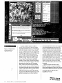
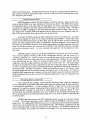
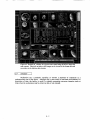
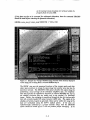
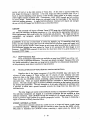
Figure 1. MclDAS image
display window
other programs
MclDAS
display
MclDAS
the processing
image source,
Overlay
that can also be dynamically
alqlQl_
PA|
|
graphics
can be either merged
or drawn as "peelable"
t2
,'
February
199,_
• Informat,on
with the image data
graphics
or transparency
with a single key stroke.
Systems
window,
Newsletter
display
Figure
illustrating
with overlaid
I shows
the
graphics,
and a text output window.
eliminate
user interface
with the command
until users become
syntax is
proficient.
To
the need to learn the syntax of different
commands,
later. The overlay
graphics
command
thus necessary
can be drawn
the user to peel off and on the
window
frame.
certain familiarity
allowing
image display
in the overview
images
on each
and, most important,
overlays,
a view of the MclDAS
of the thumbnail
MclDAS-eXplorer
saved in independent
files for redisplay
tools by clicking
At its core, McIDAS and MclDAS.-eXplorer
are command-driven
and not menu-driven.
A
graphics
graphics
by using other MclDAS
keeps track of the
its calibration,
the navigation.
image in the
For each frame that
MclDAS
view of some of the data
imported into a workstation in a single frame.
More information
about the data can be obtained
much more
than just the visible
an image,
status.
screen
frame contains
environment.
contains
figure shows a browse
either by the user or by
to determine
The display
information
step. This processing
a graphical
user interface
(GUI) has
been developed for MclDAS-eXplorer
so that
both text or command line and a GUI are
available.
The command
mented by function
line and the GUI are supplekeys and single letter key
a
strokes to communicate
The
The function
with McIDAS-eXplorer.
keys are user-programmable
to fit
lllHiilliiilllHI
I_|lllilllll
Disrq..AY
J
m: O I_I_LAY
cr
N_ll
r_
J
(s)l
Ulllun
Inllialnllll
llll
Illllli
iUnillllUllilllnl
ill|llllll
uI
.=,=i
context-specific
application needs and can be
saved and restored via "string tables" that
characterize the workstation context. A specific
function key menu can also be created by the end
user for a specific purpose.
Pipeline processing of data can be accomplished directly as well. A MclDAS application
program can start the execution of another
existing application, either synchronously or
asynchronously as desired. Implementation of
radiometric calibration, filters of various types,
navigation and cartographic projections, image
enhancement, multispectral classification, time
series analysis, area and distance measurements,
and cross sections. Map outlines and gazetteer
files provide the ability to visually identify the
geographic features. General-purl:x:rse utility
applications provide housekeeping
data migration.
Two-dimensional
functions and
irregularly spaced data can
such an application by the end user is possible if
the user is comfortable writing a FORTRAN or
be objectively analyzed onto grids, and gridded
data themselves can be graphically displayed via
C language program with the benefit of the
contour plots and cross-section plots, as well as
McIDAS applications programming
some knowledge of McIDAS.
rendered into images. A basic spread sheet
capabilit2, allows arithmetic operations on the
manual and
gridded data to compute other derived quantities.
Tools
A variety of tools are available to manipulate
the data within MclDAS-eXplorer. For solar
system image data, these include geometric and
Spectral data can be displayed, averaged, and
staged for further processing as desired for
temperature retrievals or other analysis.
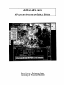
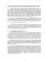
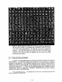
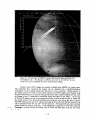
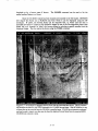
Figure2. An Earth-b_
telescopicimageof Jupiterwith
an overlaylatirude.tlongit_de
grid
anda viewof availableGUIs
lmiNRNmlflll
INNNBUNNN|NgHBBUH
lil*-_._
IHI
......
NNNHINNNI
IMNn|UNNINHNNNNNNualINI
ImiuualmmlnannnaaMunwlnl_
Currently
import,
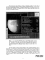
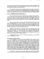
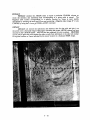
Figure
two
3.
in a
points
SAR
process
and analyze
from PDS CD-ROM
A line plot between
arbitrary
Magellan
MclDAS-eXplorer
planetary
volumes,
from most routinely
available
and Earth-based
weather
Flexible
Image
These include
telescopic
Transport
Voyager
System (FITS) formal
and Magellan
images
of Venus'
the Pioneer Venus
surface;
images of Venus can be calibrated
geometry)
and navigated.
reflectivity
MclDAS-X,
imported
gridded,
In!ormahon
Support for other data
once the data are available.
of irregular
Systems
objects,
for
such as asteroids
moons and ring systems will be
permit.
Once these data are
within MclDAS-eXplorer,
map projected,
Newsletter
Support
animated,
they can be
brightness
tools.
of an Earth-based
with an overlay
grid and a view of some of the
Figure
3 shows
a line plot
between two arbitrary points in a Magellan
frame that shows the variation of the radar
possible
added as resources
•
image of Jupiter
two points.
and the smaller
1994
and
of up to six
and navigated
using general
Figure 2 shows an example
products such as those from the Clementine,
Mars '94 and Cassini missions should also be
navigation
February
(shading
composites
image data can be used for areal cloud motion
GUIs available.
and Galileo
Calibrated
and other measurements
latitude-longitude
SAR
Three-color
classifications
bands are possible.
telescopic
images of the giant
and their satellites
Orbiter Cloud Photopolarimeter
•
satellite
images in the
planets
and filtered.
and multispectral
images
as well as images
frame
images
14
normalized
is able to
(dB) along the path between
MclDAS-eXplorer
Science
and Engineering
of Wisconsin-
requires
which is licensed
Madison.
those
a copy of
by the Space
Center at the University
For further
contact the author at: (608) 262-9541;
[email protected]
SAR
information
MCIDAS-EXPLORER
A PLANETARY
Space
ANALYSIS
Science
University
AND
DISPLAY
& Engineering
Center
of Wisconsin-Madison
SYSTEM
MCIDAS-EXPLORER
A PLANETARY
Developed
under support
ANALYSIS
#om
the Applied
AND
Information
DISPLAY
Systems
Space Science & Engineering
Center
University of Wisconsin-Madison
1225 West Dayton Street
Madison,
Wisconsin 53706
(608)262-9541
[email protected]
September,
1994
SYSTEM
Research
Program,
NASA
MclDAS-X is a licensedproductavailablefromthe
SpaceScienceandEngineeringCenter.ForlicensinginformationContact:
S.S.Limaye, SSEC/UW-Madison
1225WestDaytonStreet
Madison,Wisconsin53706
(608)262-3755
[email protected]
iv
Table
1.0
INTRODUCTION
1.1
1.2
Planetary Image Data
What is MclDAS?
1.3
What is MclDAS-eXplorer?
Object Identification
Digital Image Files
Data Description
Block
Processing
History
User Interface
1.4
1.5
MclDAS-eXplorer
Workstations
Planetary Image Data Supported
2.0
USING MCIDAS-eXplorer
Starting a session
Starting the Graphical User
MclDAS Display
MclDAS Command Syntax
Keyboard
Function Keys
Environment
Table
2.1
2.2
2.3
2.4
2.5
2.6
2.7
2.8
2.9
2.10
2.11
3.0
3.1.
of Contents
by explorer
2-1
2-1
2-2
2-2
2-3
2-3
2-4
Interface
2-5
2-6
2-7
2-8
2-9
2-9
2-9
2-10
2-10
2-11
Hardcopy output
System Status
Scheduler
Batch Mode Operation
Keyboard
Programmable
Function
Environment
Table
Keys
MclDAS-eXplorer
Commands
explorer
Tools
Importing Data into MclDAS-eXplorer
PLANETARY
DATA
SUPPORTED
1-1
1-1
1-2
1-2
1-3
1-4
1-4
1-5
1-6
I-8
1-8
BY _ICIDAS-EXPLORER
VOYAGER IMAGES OF THE GIANT PLANETS AND THEIR SATELLITES
3.1.1
3.1.2
3.1.3
3.1.4
3.1.5
3.1.6
Preprocessing
of Voyager Images
Removal of Geometric Distortion
Removal of Photometric
Distortion
Voyager Image Navigation
Center Finding
Use of Voyager SPICE Kernels
3.2
3.2.1
3.2.2
3.2.3
3.2.3
3.2.4
VENUS IMAGES: _{AGELLAN, GALILEO AND PIONEER VENUS _|ISSIONS
Pioneer Venus OCPP Images
OCPP Polarization
Maps
Magellan Images of Venus Surface
Magellan Altimetry Profiles
Galileo SSI Images of Venus
3-1
3-1
3-2
3-2
3-4
3-6
3-6
3-6
3-7
3-7
3-10
3-10
3-12
3-13
3.3
IMAGES OF MARS: VIKING ORBITER AND DIGITAL IMAGE MODELS
3-13
3.4
HST 'W'F/PC
3-15
4.1
HOW TO IMPORT
DIGITAL IMAGES INTO MCIDASEXPLORER
Magellan Radar Altimeter Data on Venus surface
Magellan Global Topography,
Radiometry,
and Terrain Data (GxDR's)
Mars Digital Image Model (MDIM's)
Data
Viking images of Mars and its moons
Voyager images of the giant planets and their satellites
Images with FITS headers
All other images
4.1.1
4.1.2
4.1.3
4.1.4
4.1.5
4.1.6
4.1.7
4.2
4.2.1
4.2.2
4.2.3
4.2.4
4.2.5
4.3
4.6
4.7
4.8
4.8.1
4.8.2
4.8.3
4.8.4
4.8.4
IMAGES
HOW TO NAVIGATE
TARGET
AN IMAGE
OF A SOLAR
SYSTEM
4-4
4-5
4-5
Navigation Reference Frames
Navigation Types in explorer
Voyager (ISS) Images of giant
kernels
planets and satellites
without
SPICE
4-6
4-7
Earth based telescopic images of planets
Viking Orbiter images of Mars
Spin Scan Pioneer Orbiter Cloud
Photopolarimeter
Images of Venus
Generic Navigation Recipe for Framing Camera Images
Finding the Limb Points and Image Center
Specifying the Image Center
Using the found center for navigation
Recomputing
the Sub-observer
and Sub-solar point data
How to Update SPICE Kernel Navigations
of Planetary Images
HOW TO MEASURE
DISTANCES
and AREAS
IMAGE OF A PLANET
OR A MOON
HOW
TO DIGITALLY
HOW
TO DETER_flNE
FUNCTION
HOW
FILTER
THE
WITHIN
4-8
4-8
4-9
4-9
4-10
4-12
4-12
AN
4-13
AN IMAGE
PLANETARY
4-13
PHOTOMETRIC
4-14
TO REMOVE
THE PHOTOMETRIC
FUNCTION
FROM AN IMAGE OF A PLANET
OR A MOON
HOW TO EXA_flNE
IMAGE
DISPLAYED
IMAGE
DIGITAL
DATA
4-15
IN A
4-16
HOW TO ENHANCE AN IMAGE
Black and White Enhancement
False Color Enhancement
True or Three Color Display
Digital Filtering
Digital Data Modification
4-1
4-2
4-2
4-3
4-3
4-3
4-4
4-4
or Enhancement
vi
4-17
4-17
4-18
4-18
4-19
4-19
4.9
HOW TO OBTAIN
IMAGE/AREA
4.10
HOW TO MAP
4.11
HOW
INFOR_ATION
ABOUT
AN
4-19
PROJECT
TO GENERATE
IMAGE
4-20
IMAGES
A THREE-COLOR
COMPOSITE
4-24
4.12
HOW TO CLASSIFY
A MLrLTISPECTRAL
4.13
HOW TO M:EASURE
CLOUD
4.14
HOW TO EXPORT
DIGITAL
INLAGE
MOTIONS
I_LAGES
4-27
FROM
4-27
MCIDAS-eXplorer
4.15
HOW TO CREATE
5.0
MCIDAS-EXPLORER
5.1
EXPLORER
5.2
5.3
AREA DIRECTORY
COORDINATE
SYSTEMS
5.4
DATA
5.5
CALIBRATION
5.6
AUDIT
AREA
A FUNCTION
DATA
KEY MENU
5-1
STRUCTURES
5-2
FOR THE
IMAGE
BLOCK
5-5
5-11
5-13
BLOCK
5-27
BLOCK
5-27
TRAIL
APPENDIX
I
Mc[DAS-EXPLORER
COMMAND FORMATS
APPENDIX
II
MCIDAS-EXPLORER
SYSTEM DATA F1LES
SUMMARY
4-28
STRUCTURE
DESCRIPTION
APPENDIX
4-26
III
OF EXPLORER
COMMANDS
GLOSSARY
,,ii
1.0
INTRODUCTION
This document describes MclDAS-eXplorer,
a set of planetary
analysis tools designed
for the MclDAS
environment.
MclDAS
is Man Computer
Interactive
Data Access System
developed by the Space Science & Engineering
Center (SSEC) of the University
of WisconsinMadison
(Suomi et al., 1983).
Somewhat
earlier,
in late 1960's a similar facility was being
born at the Jet Propulsion
Laboratory
(JPL) called Video Information
Communication
and
Retrieval
(VICAR) for analysis of the data being returned from the space probes such as the
Mariner 6 mission to Mars (Castleman,
1979).
MclDAS
originated
as a tool for providing
interactive access to the earth weather satellite data during the 1970's when there was a dearth
of adequate hardware
and software tools.
While specific hardware
elements are a key part of
MclDAS,
it is primarily
the suite of software
tools that has made it particularly
useful in
national and international
operational
weather
facilities
for integrating
vastly different
data
weather sources and providing
a coherent access to the user.
Many of these capabilities
are
also applicable to the analysis of the planetary data returned by NASA's solar system missions
of the past (Viking, Voyager, Magellan),
current such as Galileo and Mars Observer
and future
such as and Cassini or the Pluto Fast Flyby.
However,
because of the different nature of the
data and target objects, many adaptations
or modifications
are necessary.
MclDAS-eXplorer
constitutes
these adaptations
and includes other specific tools for analysis of the planetary data.
This document
is intended as a companion
document
to the MclDAS-X
OS2 User Guides.
For the most part however,
the need for documents
is rare
planetary data manipulation
needs are addressed
in this volume.
1.1
Planetary
Image
or MclDASas majority of
Data
While it may appear that the remote
sensing data such as images
returned
from
LANDSAT
or SPOT satellites and data from weather satellites
have much in common,
and
hence the same analysis tools (e.g. many of the Geographic
Information
Systems packages) can
suffice, the differences
between the two are apparent in the way these data are utilized as well
as in their content.
These differences
can be illustrated
by the presence
of clouds in the
satellite data-- for geographic
remote sensing applications
the presence of clouds is a hindrance
to the analysis of the underlying
surface data, yet the presence
of the same clouds in weather
appiications
is used for determining
the atmospheric
flow and radiation
budget
or storm
development.
Further,
the information
for geographic
applications
is concentrated
in the
spatial
and spectral
domain
whereas
for meteorological
applications
the information
is
contained
primarily
in the time domain
and in spatial and spectral
domain
for climate
applications.
The spatial resolution
of the data as well as coverage
is also a distinguishing
factor.
For geographic
and geologic
applications
highest
achievable
spatial
resolution
is
desirable
whereas for weather and climate applications
global and temporal
coverage
is more
important
than high spatial resolution.
Planetary data in general differ from both the geographic
satellite remote sensing data
and the terrestrial
weather satellite data in several key aspects.
First of all while some data is
analyzed
in near real time for mission sequencing
and public affairs reasons,
much of the
scientific
analysis is carried out later.
The data is usually acquired over a limited period of
time and is often unique.
Thus while we have global weather
satellite data for nearly two
decades, we have less than two days worth of images of Venus from Galileo and for several
weeks each year from the Pioneer Venus Orbiter.
At the other extreme we have the radar
investigation
of the surface of Venus from Magellan at a resolution
of 120 meters providing
mapping of a planet that is unmatched
even by the data available about our own planet due to
difficulties
of mapping the ocean bottom.
1.2
What is McIDAS?
Very briefly, MclDAS provides a multiprocessing
software and hardware environment
for multiframe
display and analysis of and interactive
access to any multi-dimensional
data.
Data are rendered onto the two-dimensional
display device of the user workstation
on as many
frames as the hardware
capabilities
allow.
A user interface allows as many analysis tasks as
practical (limited by the workstation
resources) and animation.
Currently
three different flavors of MclDAS
are supported
by SSEC.
They are
MclDAS-MVS
that runs on mainframe
computers
capable
of running the MVS operating
system (IBM or compatibles),
MclDAS-OS2
for IBM compatible
personal computers
capable
of running the OS/2 operating system, and MclDAS-X
for UNIX workstations
that support the
X-windows
environment.
The MVS environment
also typically includes satellite data ingestors
for earth weather satellite data and a variety of inputs through other communication
networks
to ingest other types of data such as weather forecast model outputs, conventional
surface and
upper air station data, surface radar data, lightning data etc. These ingestion capabilities are of
course not required for analysis of planetary data.
The other hardware
element of MclDASMVS and MclDAS-OS2
versions
is a SSEC designed
workstation
called the "Wide Word
Workstation"
(WWW).
This workstation
is controlled
by an IBM PS/2 personal computer and
is capable of storing and displaying
up to 1500 image/graphic
frames in its video memory
allowing animation at video refresh rates. The interface to this workstation
does not yet exist
for the RISC-6000 series computers although it is technically
possible.
For reasons of technology
and price vs. performance,
the UNIX workstations
from
different vendors such as Silicon Graphics,
IBM (RISC-6000
series), Sun Microsystems
and
Hewlett Packard,
MclDAS software has been ported to the X-Window
environment
which is
supported
by these workstations.
At the moment all of the new planetary
code has been
developed
for the MclDAS-X
environment,
however,
it can be easily ported to the OS2
environment.
Finally, a general observation
about McIDAS is in order.
By comparison
with many
of the commercial
applications,
particularly
in the Mclntosh
and Windows 3.1 domains, the
user interface used by MclDAS may seem dated.
The primary reason why the interface has
not yet changed
is that MclDAS
is used at many operational
meteorological
facilities
throughout
the world
as well as colleges
and universities
in the US.
The hardware
environment
MclDAS is used under ranges from IBM compatible
personal computers based on
lntel 80386 (or later processors),
UNIX workstations
and mainframe computers running MVS
operating system (with SSEC designed and built workstations).
The existence of a diverse user
community
implies user support and performance
across platforms.
As the port to the Xenvironment
matures the interface is being modernized
as more users move to the X-Windows
environment.
1.3
What
is McIDAS-eXplorer?
MclDAS-eXplorer
is a software enhancement
package for MclDAS
(currently only for
the X-version).
This is intended to provide support for analysis of planetary data acquired by
NASA's numerous
solar system missions.
As the missions to different planets have different
instrument
systems, the planetary data span a large range in terms of data quantity, type and
global coverage.
It is neither possible nor desirable to provide support for all types of data.
The strength
of MclDAS
is in its ability to interact
with satellite
data for geophysical
applications
such as multispectral
imagery, surface network data and atmospheric
soundings.
To that extent the enhancements
described
here provide support for planetary image data from
missions such as Mariners, Vikings, Pioneer, Voyagers and Magellan as well as from Hubble
1-2
SpaceTelescope. In addition,otherplanetarydatasuchas Magellanaltimetrydata, Pioneer
andMariner9 Marsoccultationprofiles,VoyagerIRIScanalsobe accessed
andprocessed.
The tools developedto ingestthe different datainto MclDAS and specificplanetary
applicationsare describedherein. Thus the user also needsaccessto the MclDAS-X User
handbookto beableto utilizethe standardMclDAS capabilities.
In the pastthe differentmissionsusuallyprovidedthe datain the form of Experiment
DataRecord(EDR)tapes. Supplementary
navigationdatarequiredto analyzethesedatawere
providedasSupplementary
ExperimentDataRecord(SEDR)tapes.The processof usingthese
datafor analysisrequiredcustomsoftwarefor eachmissionandeachinstrument. Fortunately
thesituationis muchimprovednowwith the adventof the CD-ROMs. Muchof the planetary
dataare now beingmadeavailablethroughthe PlanetaryData Systemon CD-ROMSwhich
allowssomecommonalityto accessing
thesedata. However,the SEDRdatasuchastrajectory,
pointingetc. arenot yet availablefor all the CD-ROMSalthoughlimited dataare availableas
SPICEkernels.
Thereare manycapablesoftwareproductsavailablewhich unfortunatelycanbe used
only with specificdata, particularlyterrestrialdata. With manysuccessfulmissionsto the
solarsystemtargetswe nowhavean immenseamountdatacollectedat numerousobjectsthat
are as diverseas the airlessmoonor Mercury to rings of Neptuneas well as cometsand
asteroids. The only thing commonabouttheseobjectsis that they have vastly different
physicalpropertiesbesidesthe fact thatthe opportunitiesto collectdataon thesetargetsfrom
spaceprobesarelimited. Oneof thegoalsof the development
of MclDAS-eXplorerhasbeen
to providea unifiedapproachto the analysisof thetargetdependent
databy accountingfor the
differencesin their physicalcharacteristicssuch as size, shape,etc. To this end, the
NavigationAncillary InformationFacility's (NAIF, at JPL) approachof assigninga unique
identificationtag to eachobject(andspacecraftfor that matter)is adoptedwithin MclDASexplorer with someenhancements.
AlthoughMclDAS-eXploreris generalenoughto beutilized for mosttypes of data, its
strength is in analysis of multispectral
images or data that can be visualized
as a two dimensional
image.
McIDAS-eXplorer
also has tools for analysis of atmospheric
data such as
temperature
profiles which although are one-dimensional
individually,
are typically
available
globally for planets such as Mars, Venus, and of course, earth.
The Infrared Radiometer
Interferometer
Spectrometer
(IRIS) instrument
on Voyager
1 and 2 provides
spectra for the giant
planets from which temperature
profiles have been derived.
I
Obfect
Identification
]
The (NAIF) software developed
at JPL uses an identification
number for each solar
system object for ephemeris
purposes.
This same number is used within MclDAS-eXplorer
but with a small modification.
This identification
process serves another
purpose
besides
naming the object in the image-- it is used to retrieve the object's
physical constants
(radii,
length of day etc.).
In most cases the planetary
data refer to a single target object such as a
planet or its satellite or ring system.
Occasionally,
however,
there can be multiple objects in a
single frame such as the images of a planet and its ring system or a satellite in the same frame.
In such cases the decision on which NAIF identification
number
to use within MclDASeXplorer
is made on the basis of which
single object
is being
analyzed
in that frame.
Another
complication
arises in investigating
images of bodies
with extended
atmospheres such as Venus or Titan.
The visible or infrared images of these planets do not "see"
the surface but only the cloud-top level, which is about 65-70 km above the surface for Venus
1-3
andnearly300km for Titan. Thusthe effectiveradiusfor suchobjectsneedsto bedifferent
for the purposeof not only imagenavigation(theprocessof relatingthe imageco-ordinates
to
the planet'sco-ordinatesandvice-versa),but alsofor measuringdistancesetc. For this reason
MclDAS-eXplorerdistinguishesbetweenthe solid surfaceand the cloud level. Further,this
level canbedifferentat differentimagingwavelengths
suchasfor Saturn,thereforallowanceis
madefor havingasmanyas9 separateradii for differentlevelsfor objectswith atmospheres.
The NAIF identificationcodefor an objectis enteredas a four-digit numberratherthanasa
threedigit number,with therightmostdigit denotingthe level for whichthe radiusis defined.
Thus,for Venus,the NAIFID valueof 299is modifiedto 2990for the solidsurface,and2991
for the cloudlevel at the first wavelength,2992atthe secondwavelengthetc. Themnemonic
identification is also suitably modified as appropriate,for example,to Venussfc or
Venusarm.
m
Object specific physical constants
that are required for analysis or navigation of the
data are obtained through a single subroutine.
The physical constants
for each solar system
target that are incorporated
within MclDAS-eXplorer
can be listed with the PHYSCON
command.
This subroutine
contains the most-recent
published values of the triaxial radii and
the length of the day for solar system objects.
If any of the data need to be updated, then this
subroutine
needs to be recompiled
after the required changes,
and all of the planetary
code
needs to be relinked
as well.
This is done as a matter of precaution
to ensure that the
fundamental
constants are not changed inadvertently
(as is possible if the constants were loaded
from a data file-- there is no simple accountability
if the file gets modified).
McIDAS-eXplorer
allows use of the SPICE kernels for the navigation of images and
also provides tools to determine the navigation
transforms
when the kernels are not available
but the basic trajectory
and pointing information
are available.
Data from the older missions
such as Viking Orbiter and bulk of Voyager imagery fall in this category.
[
Digital
Areas
or Image Files
[
Although
the CD's offer a convenient
means of archival of image data, the speed of
access is less than desirable.
For this reason and for reasons of compatibility
with the
MclDAS
environment
as well as efficiency,
the image data is imported
into the MclDAS
environment
as files.
At the same time a Data Description
Block is created that provides a
road map to the navigation,
calibration
information
for the image data.
While there is some
commonality
between various formats, mission and science instrumentation
differences
result
in mission specific variations.
These are accommodated
by classifying the DDB's into specific
models such as one for framing cameras, one for spin scan imagery, one for nadir pointing
scanning
instruments
etc. The Magellan
SAR and altimetry
data are exceptions
in that the
image products are available only as mapped products (various compressions
achieved through
sampling) while the latter is mostly available along orbit tracks.
used.
given
The datafile structure
is described
in detail in Appendix
III for the different models
A brief overview
of the files used by MclDAS for storing the imported image data is
below.
MclDAS-X
stores image data in files called "areas" all of which have names of the
form "AREAxxxx"
where xxxx is a four-digit number.
Each "area" contains one single image
which can be multibanded.
As many as 9999 areas can be accessed by MclDAS from the
"/ul/mcidas/data"
sub-directory,
and more can be allocated by using a second sub-directory.
This sub-directory
can be thought of as workspace
for MclDAS-X,
and needs to be large
enough to accept the data to be accessed as well as for any output created, and typically this is
the largest sub-directory.
With each area basic information
about the data contents regarding
acquisition
time, source instrument,
calibration,
navigation,
and format is stored in a carried
1-4
alongthe processing
chain. StandardMclDAS-X file formatfor multidimensionalspectralimagesincludesa directoryblock(64 words)aswell asa 128-wordblockcontainingthe navigation informationfor thedata.
[
Data Description
Block
]
MclDAS-eXplorer
extends the data directory
concept by using an additional
Data Description Block (DDB) in as many multiples of 64-words as needed.
The DDB allows access
to detailed descriptors
of the data about the target object, the source instrument,
data acquisition geometry,
calibration
and other ancillary information
that is potentially
useful.
The exact
definition of a DDB is dependent on the instrument type that returned the data. Thus the Voyager images have a specific DDB type defined which is different
from the Magellan radar images of the Venus surface which are available only in map format.
At present the DDB concept has been implemented
only for the image data.
has adopted a standard for labels for the datasets produced
on CD-ROM's.
These
usually include information
present on other labels such as VICAR labels as well as
history and other mission specific labels or information.
MclDAS-eXplorer
tools to
PDS data from CD-ROM's
in general will include the complete text label associated
image file and also extract a set to encode into the DDB so that McIDAS-eXplorer
can use that information
easily.
As work proceeds,
this approach
will be adapted
The PDS
PDS labels
processing
import the
with each
commands
for other
data types.
MclDAS-eXplorer
adheres to the general MclDAS-X
conventions
for the file system.
Thus the data ingested normally
reside in the /mcidas/data
directory
and the source is in
/mcidas/src
directory,
etc.
Specific formats for storing and accessing
the data are specified
under MclDAS-X
such as image data (two or three dimensional),
gridded data (two dimensional gridded
data sets e.g. output of numerical
models) which is usually coarser than the
image data, and other single dimension data types such as time series, etc. The exact implementation of the different formats is dependent on the native operating system, but McIDAS-X
provides a transparent
and a common interface between the applications
software and the native
operating system.
The basic file system is called the Large Word array or LW format.
Both
the digital image data and the grid-data formats are based on the LW file system.
For both the
gridded and the image data sets a directory service is provided to query the contents of the file.
MclDAS-eXplorer
uses certain extensions for planetary applications
which are compatible
with
MclDAS-X.
[
Processing
History:
Audit
Trails
]
Most spacecraft
data undergo
several specific processing
steps, some are mandatory
such as radiometric
or geometric calibration,
many others are optional such as map projections
or multispectral
classification.
In most instances wherein
a large amount of data are being
analyzed,
it is useful to maintain a processing
history record for the data.
For the image data,
MclDAS-eXplorer
maintains
an audit trail in which applications
programs
append an entry
containing
all the command
parameters
that were invoked in that particular
processing
step.
This processing
history can be queried either by the user or by other programs to determine
the
processing
status.
MclDAS has been ported to the OS/2 operating systems as well as to several versions
of UNIX.
The primary application
code is mostly written in FORTRAN
with some C language code. To a large extent MclDAS acts as its own operating
system and most housekeeping activities can be performed
from within MclDAS
itself.
Nevertheless,
experience
with the
native operating
system is useful but proficiency
is not necessary.
As MclDAS
predates most
personal computers
and certainly
the windows
environment,
it is not surprising
that the pri-
I-5
marymeansof interactionwith the useris throughthe commandline. Howeverotheruserinterfacesarepossibleandhavebeendeveloped
andimplemented
within MclDASin thepast.
MclDASdiffers from mostotherimagedisplayandanalysisenvironments
in that it is
a multitasking,multiframeintelligentdisplayenvironment.In fact, to the user,MclDAS functions as a pseudooperatingsystem,providing someof the basicfunctionsof an operating
system.Further,it providesthe userwith a pass-through
connectionto the operatingsystem.
MclDAS supportsmultitaskingsuchthat while oneuserapplicationis beingexecuted,others
can be invokedas neededandlimited only by the hardwarecapabilities. The intelligence
derivesfrom the factthat thesystem"knows"the key dataattributesof the imagesas well as
graphicsdisplayedin different framesand this informationis availableto the application
programs.This is crucialfor quantitativeanalysisin a multitaskingenvironment.
Executionof a profile file setsthe displayenvironmentflags suchas numberof bits
displayed,initial numberof framescreatedat start-up,sizeof the displayframes,defaultfont
for text andgraphicswindows,imagedisplaymode(24-bitthree-colormodeor 8-bit false
color)etc. For example,on workstationswith 24-bitgraphicsthe sessioncanbe startedas:
mcidas-bp24 -ig y -fr 24 48 -imsiz256256
This startsa sessionwith independent
graphics("W" key togglesthe graphicson and
off the image),with 3-color256 lines x 256 elementssizeddisplayframesof which 24 are
allocatedinitially andup to 24 morecanbeallocateddynamicallyfromthe McIDAScommand
window(usingthe MAKFRMcommand).Theframesthatarecreateddynamicallycanbe of
anysizeaslimitedby theavailableworkstationmemory.
[
MclDAS-eXplorer
User Interface
]
MclDAS-X
typically creates four "windows" on the workstation
screen when a session
is started.
One of these is a "command"
window which also includes a status line (Figure 1)
and is the primary user interface to MclDAS.
There are multiple text windows ("1" and "2")
of which only one is active at any moment (selected by clicking on a mouse button in the particular window or from the numeric-keypad
by pressing "1" or "2" key).
The window active
when a command is entered contains the output from that command.
The fourth window is the
image display which is sized according to the frame size specified in the start-up procedure.
MclDAS-eXplorer
supports various forms of user input- text or command
oriented,
supplemented
by function keys and single letter key-strokes
and a Graphical
User Interface
(GUI).
The function keys are user programmable
to fit the particular
application needs as well
as utilized in a a menu system which is invoked with the ESC key (which prompts the user for
the name of a menu file).
The user can communicate
his input to eXplorer
in two other ways besides the
Command window.
The GUI is based on the Tcl-Tk script and is user tailorable as well as a
Function Key based menu system, which can also be adapted by the user as needed. These two
interfaces make it unnecessary
to know the syntax or even the command names and most tasks
can be accomplished
readily through the interface.
The GUI does require some familiarity
with the scripting language if it needs to be modified by the user (although in most cases it is
unlikely) and is completely
independent
of the commands.
It is a system of cascading menus
that offer different tool-bars which can be chosen with mouse-button
clicks.
When needed,
these will prompt the user for input.
1-6
The function key basedinterfaceis similar in operationin that it is also a set of
cascadingmenuswherethe choiceis madeby pressinga specificfunctionkey. Only minimal
userinputis possiblewith this scheme.It is howevermuchsimplerto createandcanbeeasily
manipulated
with a text editor. The details of how to write a function key based interface can
be found
in the MclDAS-X
manual.
Figure 1.1. A view of the MclDAS-X screen.
The Command window is at the
bottom, the text message window to the upper right and the image window is on the
left. The graphics in the image window can either be independent (either graphics or
the underlying image can be toggled into view) or merged with the base image. The
status line on the top of the Command Window indicates the current state of the
display.
The GUI interface currently
supported
makes the use of MclDAS-eXplorer
easy for
novice users. An initial tool-bar window allows selection of a particular
function supported
by
MclDAS-eXplorer.
Clicking with the mouse-button
(left) opens a newer window giving the
user other choices that activate specific MclDAS commands
and allow solicitation
of input for
command parameters.
This interface allows the help to be made available in a context sensitive
manner and is independently
controllable
separate
from the command
itself and is being
developed
using the Tk-Tcl scripting
language.
An example
of this interface
is shown in
Figure 2.
ORI_NAL
1-7
PA_
Ill
Figure 1.2.
An illustration
of the Graphical
which tasks can be chosen with mouse-button
User Interface
clicks.
that cascades
menus
from
Press ESC ke_ to Exit Menu
Figure
1.3.
An illustration
of the Function
Key based
User
interface.
invoked from a text file containing
the menu script _ith the ESC key.
create custom menus for different applications
and invoke them as needed.
1-8
This
one
is
The user can
1.4
McIDAS-eXplorer
Workstations
The foremost requirement
for MclDAS-eXplorer
is to have convenient
access to the
current and future planetary
datasets.
Data from missions such as Voyager
(giant planets),
Viking (Mars) , Galileo (Earth and Venus) and Magellan (SAR imagery of Venus and surface
altimetry, reflectivity,
emissivity)
data are available on CD-ROM's
through the Planetary Data
System and the National Space Science Data Center (NSSDC).
The workstations
required to
use MclDAS-eXplorer
are the ones that can run MclDAS-X
with the exception
that a CDROM reader needs to be available either locally or over a Local Area Network
(I.AN).
A
typical configuration
is a UNIX based workstation
(SUN, SGI, IBM/RISC-6000,
HP) with 32
mb or more memory,
1 Gb or larger capacity disk, and a DAT or an Exabyte tape drive in
addition to the CD-ROM reader.
A color display, preferably
with 24-bit display capability
is
desired but 8-bit display support is adequate for many applications.
Similarly,
a CD changer
such as the Pioneer DRM-604X
can also be useful to provide
access to as many as 6 CD's
simultaneously
(not synchronously
of course),
but not necessary,
and of course
can be
expanded
through the SCSI interface to handle as many as 48 CD's on-line, up to 8 of the
minichangers
(daisy-chained
to the SCSI port) simultaneously.
1.5
Planetary
Data
supported
under
MclDAS-eXplorer
The following data are planned to be fully supported
for analysis in terms of navigation
and data calibration.
In addition to the following,
earth based telescopic
images of solar
system targets can also be readily imported
and analyzed using MclDAS-eXplorer
if the data
are available in a standard format such as FITS or TIFF.
Earth
and Moon
Data from
METEOSAT
all US civilian
meteorological
satellites
(GOES,
POES)
and GMS (European
and Japanese geosynchronous
satellites).
Galileo Orbiter SSI images
and December
1992.
during
Earth
1 and Earth
2 encounters
as
in December
well
as
1991
Venus
Magellan
Mosaicked
Image Data (C- and F-MIDR's)
on PDS CDs MIDRCD.01
MIDRCD.120
and Altitude and Radiometry
Data CDs on Volumes
ARCDRCD.001
through
ARCDRCD.015
and
Composite
Global topography
and Radiometry
Data,
GxDR 3002
Pioneer
Venus Orbiter
Pioneer
Venus OCPP
Galileo
SSI images
Cloud Photopolarimeter
Polarimetry
of Venus
(OCPP)
images
Maps from NSSDC
archive
tapes
(GO_0002).
Mars
Mapped
Viking
Jupiter
Image
Orbiter
Data Model
Images:
(USGS):
PDS Volumes
MDIMS
volume
VO_1001
1-6
through
VO_1006.
and Satellites
Voyager
1 and 2 images on EDR tapes and PDS CD-ROM
Volumes 6-8 and Volumes
13-25 (Volume 17 is the last one published so far, more are forthcoming).
I-9
HubbleSpaceTelescope
imagesof Jupiter.
Earthbasedtelescopicimagesof planetswith FITSheaders.
Saturn and Satellites
Voyager1 and2 imageson EDRtapesandPDSCD-ROMVolumes4-5.
HubbleSpaceTelescope
imagesof Saturn.
Uranusand Satellites
Voyager2 imagesonEDRtapesandPDSCD-ROMVolumes1-3.
Neptune,RingsandSatellites
Voyager2 imagesonEDRtapesandPDSCD-ROMVolumes9-12.
References
Castleman,K.R., 1979.Digital ImageProcessing,PrenticeHall, EnglewoodCliffs, New
Jersey,429pp.
Suomi,V.E., R.J. Fox, S.S.Limaye,
interactive
and W.L.
data display system.
J. Clim.
1-10
Smith, 1983. MclDAS III- a modern
Appl. Meteor..
22, 766-778.
2.0
USING McIDAS-eXplorer
MclDAS-eXplorer
is a set of specific commands
or applications
programs
that can be
run under McIDAS-X
and familiarity with McIDAS-X
workstation
environment
is useful.
The
current
release of McIDAS-X
and eXplorer
also support a Graphical
User Interface
(GUI)
based on the Tcl-Tk scripting language.
This GUI provides access to many of the commands
in an intuitive manner using toolbars.
Help about specific commands,
a glossary,
a tutorial
section on how to accomplish certain tasks is also accessible via this GUI.
A completely
GUI
based version of McIDAS-X
called MERLIN
is also available via anonymous
ftp. McIDAS-X
capabilities,
installation
notes can be found in the Users Guide available
from SSEC.
For
novice users a brief introduction
to the McIDAS concepts is given here.
Starring
and ending a MclDAS
At the console login,
The user ID and the password
If the X-server
session
enter the user ID and the password
to log onto the workstation.
are created by the system administrator.
is not running,
start it with xinit.
To start MclDAS,
simply
enter at the
prompt:
mcidas :2ig
; : ;.
:
:
i
from your home directory.
This initiates execution of the mcidas profile file which sets the
display environment
flags such as # of bits displayed,
number of frames created at start-up,
size of the display frames etc.
The contents of the profile are described
in the MclDAS-X
User's Guide.
Note that it is when starting a MclDAS
session that the frame size and the
number of gray levels displayed gets set (leave it at 128 unless the workstation
has more than a
single 8-bit display plane).
Details of starting MclDAS with different numbers of frames and
different sizes may be found in the MclDAS-X
Users Guide.
Note that the frame size defined here is the MclDAS
display flame size.
The Xwindow within which this display appears is initially set to this size and should normally
not
be changed.
Once the MclDAS
session has started,
expanding
or shrinking
the display
window
(or the "image"
window for MclDAS)
has no real effect on the amount of data
displayed
by McIDAS in that window.
Thus the frame size should be set to the largest size of
the image that needs to be seen at the full resolution
since by integer sub-sampling
larger
images can be seen in a small display frame.
MclDAS-X
creates several "windows"
when a session is started, typically,
four.
One
of these is a "command"
window which also includes a status line (Figure 1) and is the primary
user interface to MclDAS.
There are two text windows C I" and "2") which are made active
by clicking in the particular
window or from the numeric-keypad
by pressing
"1" or "2" key.
These two text windows contain output from MclDAS commands.
The fourth window is the
image display which is sized according
to the frame size specified in the start-up procedure.
To close
end a session.
Starting
a MclDAS
the GUI
The eXplorer
session,
simply
enter
EXIT
in the command
[
GUI can be started
from your home directory
2-1
with:
window
which
will
i_il
i_iiLiiiiiii
iiiii_!_!i__i___
_ _ _ _iliii!ili
i!!!iiiiiliiiigiiiii
iiiiiiiiiii91
i iiiiii
! iiiiiiiiiiikiiii_L_k_
_iiiiiii_i_i_i_i
_i
_i
i_!_i_i
i_i_i_
i__i_i!_i
i_i_i
ii__i_i_ii_!_i
i _!_
i_
!_
!_
!_
i!i_i
where term_# is a terminal number assigned by MclDAS to the session and can be found in the
Title Bar for the MclDAS Text and Command windows.
Alternately,
the interface can also be
started from the MclDAS session with the GUI key-in from the command window.
Figure 2.1 The initial screen for the GUI that
allows the user to chose between different
actions using the mouse-button clicks on the
desired item.
MclDAS
Display
[
Since the prime motive behind MclDAS is the analysis of data acquired in the temporal
domain, animation is a key feature, and thus MclDAS uses multiframe display capability.
The
image data are displayed
on a "frame" which can contain either image or graphic data.
The
frames can be any size as desired and each one can be of a different size. If the frame size is
larger than the screen size then the screen provides a scrollable
window into the displayed
frame and can be moved with the mouse.
Frames can also be dynamically
added to a session
(as allowed by available
system memory),
but at present they can be unloaded
to free up
memory
only by exiting
the MclDAS
session
and re-starting
MclDAS
with the new
parameters.
On UNIX workstations
the number of frames to configure
and their sizes are
specified by the user (in the profile) as constrained
primarily
by the amount of random access
memory (RAM) available in the workstation.
The user controllable
frame size is useful to optimize the number of display frames for
the specific data being analyzed in that session.
Even if animation may not be a desire, a large
number of frames are still immensely useful in streamlining
an analysis session by eliminating
the need to erase and re-draw graphics as well as by keeping them around for reference.
The
planetary
image data available on PDS CD-ROMs range in size from 800 x 800 for Voyager
and Galileo to 1024 x 1024 or larger for Magellan products, a considerable
difference
in frame
size and memory requirements.
2-2
The display flame containsmuch more informationthan just the visible image in
McIDAS environment. For eachframethat containsan image,McIDAS keepstrack of the
imagesource,its calibration,and,mostimportant,the navigation. "C" single-lettercommand,
LF andWHERE commandsallow the userto querya frame'scontents. LISTDDB provides
moredetailedinformationaboutthedisplayedframe.
Overlay graphicscan be drawn which can also be dynamicallysavedin separate
graphicsfiles for re-displaylater. This is particularlyuseful in the X-environmentwherein
"peelable"graphicsare not possibleor implementedon someworkstations. Thus, if any
changesare requiredin the graphicframe, the entire contentshave to be erasedand redisplayed.
12.I
MclDASese
- Not quite a language
but a syntax
of its own
At its core, MclDAS
and MclDAS-eXplorer
are command
driven and not menudriven.
A certain familiarity
with the command
syntax is thus useful.
A Graphical
User
Interface
(GUI) and a function
key-based
interface
are also available
to execute
most of
commonly used MclDAS-eXplorer
and core MclDAS-X
applications.
The GUI is based upon
the Tcl-Tk scripting language.
The function key-based
interface
is user programmable
and
allows creation of a function-key
based menu system, and can be created using a text editor
outside of MclDAS environment.
More than one such menu can be created and used during a
single session.
The function key-based menu is invoked with the ESC key which
the user for the name of the file containing the menu script.
then prompts
Typically,
a process can be performed
with a command
entered
in the command
window
from the workstation
key-board.
Usually most commands
are task oriented
and
execute an operation
once.
Since MclDAS
is a multiprocessing
environment
in itself, user
always has the option of starting other processes
via the command
window
while one is
executing,
or via GUI or function keys. Some commands
however are interactive
and require
user attention via mouse button clicks, or occasionally,
key-board
input.
A few commands
are
memory resident, which remain active until the user either explicitly
terminates
them or they
time-out.
A command
may or may not have any arguments,
have positional
parameters
or
keywords
or both.
The positional
parameters
are generally
restricted
to certain
"obvious"
situations (but that is peculiar to the programmer!)
while keywords
are used to specify other
specific inputs.
Such keywords
are used by typing the keyword exactly (ALWAYS
in upper
case) followed by a comma or the equality sign ("=") followed by the value.
A keyword
may
accept as few as one or as many as 32 values entered consecutively
on the command
line. The
McIDAS-eXplorer
commands are expected to check the specified keywords
for validity, if any
are misspelled or extraneous
to the command,
an error message is printed out and the process
is not executed.
The keywords
come in two varietiesglobal and command
specific.
The
"global" keywords are generally recognized
system-wide,
and share some commonality
in use.
Examples
are DAY=
and TIME=
or DEVice=.
Generally
the global keywords
require only
the first three characters,
but command specific keywords may check the entire keyword.
The positional parameter
is most often used to indicate to an applications
program
the
area# containing
an image of interest.
Often it is desired to modify one image by some
process and retain the original as well. The syntax most often used (and almost invariably
in
2-2
McIDASese)is to specifyin input area#first andthe outputarea#second. For examplea
commandwith a syntaxgivenas:
REMAPfrom_areato_area
REMAP
and entered
as
101 102
will remap the image contained
in the file specified by the positional
parameter from_area
(area# 101 in this example) and write the output in the file specified by the second positional
parameter
to_area (area# 102) using the navigation transforms
defined for the two areas.
The
actual file names for the two areas are AREA0101
and AREA0102,
but the user seldom needs
to worry about the exact names except for system administration
purposes.
A simpler example of the positional
parameter
required,
such as in the LA command to list the directory
what the contents are!):
is when only a single parameter
is
for a given area (so one can find out
LA 101
which
I
101
produces
48
additional
89214
a single
83159
line of output
I
I
I
in the text window
I
I
800
800
like:
I I...............
If this is not sufficient, one can make use of the keywords
output by keying in:
for this command
to produce
LA 101 FORM=AUDIT
which queries the area to produce
the output may look like:
the audit trail for the image
2-3
contained
in the Area
101 and
area
ss
wdcld
hhmmss
89214
83159
tcor
ecor
Ir
er
zr
tsiz
esiz
z
bands
...................................................
101
48
proj:
0 created:
area
offsets:
length:
1
191147
1
1
memo:
800
---CDROM
800
1 1 ...............
DECOMPRESS---
type:BRlT
data=
36
9040
cat
vatcod:
-Audit
1
93048
ca[
type:VISR
doc
1
0
navigation=
length:
zcor:
0
I band-8:
256
calibration=
[ev
Length:
NA
reel#:*****
2816
0 PREFIX=
36
Trail
yyddd
hhmmss
PICNO=
TARGET=
0338N2-023
FDS=
10706.02
SHUTTER
TIME=
FILTER=
LINES=
89214
GREEN
EXP=
ELEMENTS=
Internal
NARROW
15.3600SEC.
and
=
/cdrom/neptune/c107Oxxx/c1070602.imq__
FDS-START
=
1070600
FDS-END
=
1070700
TARGET
=
neptune
CAMERA
=
FILTER
=
LOW
SCAN=
5:1
EDIT=
0
SEARCH_INDEX=
AREA
GAIN=
Defaults:
SOURCE
OUTPUT
VOYAGER
NAONLY
800
Parameters
NEPTUNE
SPACECRAFT=
ANGLE
83159
(5)
800
VCDROM:
CAMERA=
=
101
93048
191155
VCDROM
93119
175624
RF
93119
175657
FILLO
93119
175727
RF
93119
175813
SEDRIN
FDS=
10706.00
10707.00
AREA=
101
TARGET=
NEPTUNE
101
101
101
101
Some commands
which require no arguments
at all.
One example
shuts down an active MclDAS session and closes all active MclDAS windows.
is EXIT
which
Then there are
some
single-letter
commands
which
can be alternately
entered
using
the
ALT-key
simultaneously
with another key. These commands do not require a [CR] if entered using the
ALT key, and generally control the display state. Examples are the 'A' and 'B' key commands
which respectively
advance or back-up the display to the next frame in the sequence.
MclDAS
also makes use of user defined string tables to facilitate simpler input to application programs
as well as argument passing between different application
programs.
These
string tables are created by a simple string editor and stored in the user profile and can be
saved and deleted.
Multiple versions can be stored under different names for different applications and can be shared with other users
Besides the single command
execution
or action of
application
tools, MclDAS
applications
can be executed in a sequence
one of two distinct ways.
One of them is as a macro command that is
DAS macro program
accepts as input standard FORTRAN
statements
and can call other MclDAS applications.
Once compiled, the application
described within the macro.
2-4
for repetitive
tasks in
precompiled.
A McIwith some exceptions
executes the sequence
Thesecondwayof simplifyingrepetitivetasksis to usethe REPEATcommand,which
executesa commandstringa givennumberof timeswith anynumberof numericarguments.
For example:
TE "MAPIT !1 !2 MERGE=YES;DF !2 1
REPEATMAPIT 100TO 200BY 1 300
will map images contained in areas 100 to 200 and map into a given projection
and merge the
output into a single output area (# 300) and display the result after the addition of each image
on frame 2. This sequence is useful for making mosaics from Magellan framelets or tiles.
[2.2
Hardcopy
Text or Image output [
There are several ways of obtaining hardcopy
text and image (gray-scale
or color)
output from MclDAS-X.
The simplest
means of obtaining
a print copy of the MclDAS
command output is to use the redirect capability offered by the DEV keyword.
The Output can
be directed either directly to the workstation
printer, or to a file, simply by appending
any
command by DEV = P, or DEV = Ffilename
respectively.
The text file can then be printed
from the X-window
by any of the methods.
Note that this file is an LW file (which really
means that it lacks the carriage-return
LineFeed sequence) and must be converted to a DOS or
a text file by using DOSTOLW
command and then sent to the printer. One possible is to use
enscript:
(In the MclDAS
Command
Window):
DOSTOLW
filename text_file
OS "enscript-2rG
filename
which
will print the file as facing pages in the landscape
format.
If a complete
log of the McIDAS
work session is desired,
MclDAS
output can be also be copied to a log file using the TFILE
close the log files at appropriate times as desired:
TFILE
OPEN
TFILE
CLOSE
user key-ins
and the
command
to open and
"filename
The file can then be printed
commands.
as before
from
the X-window
using the operating
system
A third means is to use a screen capture device to print out the screen display which
may or may not include gray-scale
or color images using such as a TOYO printer which is
connected to the display device of the workstation.
Finally, the image displayed on a MclDAS frame can be
format file using the SVGIF command.
The .GIF file can then
using the XV utility from a X-Window session, either as a color
image.
The PostScript file containing the image can then be sent
get either a black and white gray-tone image, or to a color printer
2-5
printed by saving it as a .GIF
be saved as a PostScript
file
image or as a black and white
to the system laser printer to
to obtain a color print:
The .GIF file canalsobeexportedto othersystemssuchashigh resolutioncamerasor
imageeditingprogramsto addannotation,changecolorbalanceetc.
Frequentlyan X-windowis alsorequiredfor direct interfaceto the operatingsystem,
althoughmostcommands
canalsobe sentto the operatingsystemfrom the MclDAS command
windowthroughthe OS commandfollowedby a string (i.e. precededby the doublequote
symbol,") containingthe operatingsystemcommandsyntax. Exceptionsarecommandsthat
requireauthentication,
asthe "su" command.
OS"pwd (queries
the system for the current
directory).
Theoutputisdirected
tothecurrentMclDAStextwindow:
/ullmcidasldata
MclDAS-eXplorer
adheres to the general McIDAS-X
conventions
for the file system.
Thus the data ingested normally
resides in the /mcidas/data
directory
and the source is in
/mcidas/src
directory,
etc. Specific formats for storing and accessing
the data are specified
under
MclDAS-X
such as image data (two or three dimensional),
gridded
data (two
dimensional
gridded data sets e.g. output of numerical
models) which is usually much more
granular than the image data, and other single dimension
data types such as time series, etc.
The exact implementation
of the different
formats
are dependent
on the native operating
system,
but MclDAS-X
provides
a transparent
and a common
interface
between
the
applications
software and the native operating
system.
The basic file system is called the
Large Word array or LW format.
Both the digital image data and the grid-data
formats are
based on the LW file system.
For both the gridded and the image data sets a directory
service
is provided
to query the contents of the file.
MclDAS-eXplorer
uses certain extensions
for
planetary
applications
which are compatible with MclDAS-X.
12.3
System
Status
I
As MclDAS-X
is a multiprocessing
environment,
several application
programs
can be
executed simultaneously.
The respective
output can be directed to separate text windows
or
files.
Some of the applications,
such as multispectral
classification
of large images require
significant
processing
time even on fastest workstations.
It is useful in such instances
to
determine
the active applications.
A command
(SHFT-?)
provides
a current
snapshot
of the
processing
load at any instance, and an abort mechanism
also exists to abort a user process
from within MclDAS-X
(/ followed by the process
identification
number
in the Command
window).
An inventory of the data imported into MclDAS-eXplorer
is obtainable using WHERE
and LA
commands
in condensed,
text form, and visually
as thumbnail
images using the SCANA
command.
SCANM,
a memory resident
command
allows some limited operations
to be
performed
on
interactively.
the
data/areas
displayed
in
a
2-6
browse
frame
created
by
SCANA
key-in
Figure 2.2 Example of a display for a browse area created using SCANA to depict the
area contents. Practically as many as 400 images can be viewed in this format and used
as an index to the eXplorer data contents.
[2. 4
Schedule r
[
MclDAS-X
has a scheduler
capability
to execute
a sequence
of commands
at a
predetermined
time in the future.
Although this is most useful in real-time environments
for
acquisition
of data, the facility is useful to schedule processing
resources
intensive
tasks at
times when the workstation
may be otherwise idle or less stressed.
2-7
Figure2.3 Anotherexampleof a display
of a browse framecreated
from datastoredin
180 areaswhich contained
raw and mapped (polarstercographic)
imagesfrom Pioneer
Venus OrbiterCloud Photopolarimeter.
The areasmay or may not be consecutively
numbered.. Each thumbnailimage can be annotatedeitherwith the date/timeof
acquisition,
or theareaand band number as desired.The browse areaitself
istagged
with day and time when the index was generatedand can be seen on the frame
annotation
lineatthebottom.
12.5
Batch processing
of commands
]
A facility to execute commands
from a file allows systematic,
repetitive
processing
of
data effortlessly.
Any MclDAS
command
can be entered in a text file just as it would be
entered from the key-board.
The commands
in the file can be executed
using the scheduler
capability
or started from the key-board
with the RUN file_name
command.
The file can be
created using any text editor available
on the workstation
and should normally
be in the
/mcidas/data
sub-directory.
If a log of the processing
is desired,
each command
should be
appended with DEV=F
log..file_name.
Alternately,
TFILE OPEN can be used to maintain
a single log file record of the RUN output.
If any command
aborts, i.e. is terminated
the next command in the RUN file.
2-8
due to some
error,
processing
continues
with
[
2.6
Keyboard
[
For compatibility
reasons, MclDAS keyboard normally
is in CAPS-LOCK
state.
All
key-ins are KEYWORD
names are expected
in upper case only.
Note that the MclDAS
control
program
key-board
state in the command
window
is not always
indicated
by
workstation's
CAPS-LOCK
indicators. Usually this is not a problem unless a UNIX file name
is being specified in the Command window, in which case the SHIFT key must be temporarily
depressed.
All default MclDAS internal file names are in upper case.
The ESC key serves two functions
within MclDAS-X.
If this key is pressed while
typing a command in the Command window, the typed entry is cleared.
If however the key is
pressed at any other time, it prompts the user for a name of a file containing
the script for a
Function
Key based menu interface.
If hit accidentally,
a simple ENTER
will close that
window (and indeed this is necessary to return control of the keyboard to the user).
The key-board state in other X windows is not affected
LOCK indicator light if any on the workstation.
[2. 7
Programmable
function
through
e.g.:
:::::::"::_:_:_::"
:::::
Function
Keys
and is consistent
with the CAPS-
]
Often used commands
can be invoked quicker with the capability of programmable
keys.
The 12 function
keys available
on most workstations
are named KEYF1
KEYF12 and can be programmed
using the TE command with a specific command,
_:_+_:_/:::_/_
#._:._..":i_'_:?_
KEYFI
= WHERE
::_ :::_ :::::::::?:
FRAME
:: ,":::_::::: : _::_
"._
: '.:._,:_:.'::::::_",:::-'::_.'::_:_:_•'_,:."_
".".:_:_ >.:5_?.:._
:.'::_.'._:_:_
_:_::_:_'_'_
"_'
14
Anytime the function key F1 is pressed, the programmed
command
is executed.
It is also
possible to assign multiple commands to a single key by separating them by a semi-colon:
TEKEYF10
"?;WHERE
AREA
100 110;LISTDDB
10;OS "Is/cdrom
Pressing the F10 key will initiate the sequential
execution of the four commands
assigned to
that key and will first provide the MclDAS processor status, list contents of areas I00 through
110, list the Data Description
Block (DDB) for area I0 and send a command to the native
operating system to list the directory of the/cdrom
directory.
12.8
Environment
Table
]
An environment
table capability enables keyword parameters
to be passed to commands
that use that keyword.
The environment
table basically consists of keywords used by MclDAS
commands
which can be assigned values using the TE command.
A MclDAS command
will
'read' this table to scan if any of the keywords used in that command exist in the table and use
the value assigned if the keyword exists in the table.
If the keyword
is also entered via the
key-board
as part of the command, then that value takes precedence
over the environment
table
value.
TE DAY "79006
2-9
If the LA commandis thenenteredfrom the keyboardwith a certainrangeof
numbers to list, then only the ones that contain
as DAY is a valid keyword for LA.
a named
images
acquired
area
on day 6 of 1979 will be listed
The environment
table can be listed with the TL command
and saved/restored
file with the TU command.
Thus a user can create multiple environment
different
in/from
tables for
types for data analysis.
2.9
MclDAS-eXplorer
Commands
A variety of tools or commands
are available to manipulate
the data within MclDASeXplorer.
For solar system image data these include geometric
and radiometric
calibration,
filters
of various
types,
navigation
and cartographic
projections,
image
enhancement,
multispectral
classification,
time series analysis,
area and distance
measurements,
crosssections etc. Map outlines and gazetteer flies provide ability to visually identify the geographic
features.
General purpose
utility applications
provide
housekeeping
functions
and for data
migration.
Two
dimensional
irregularly
spaced
data
can be objectively
gridded data themselves
can be graphically
displayed
via contour
as well as rendered into images.
A basic spread sheet capability
on the gridded data to compute other derived quantities.
analyzed
Spectral data can be displayed,
averaged and staged for further
for temperature
retrievals
or other analysis.
Many of these commands
MclDAS-X
on which eXplorer is built.
MclDAS
commands
are generally
written
in either FORTRAN
Users may write their own applications
in the MclDAS
environment
subroutine
libraries provided as part of the MclDAS-X
license.
I
2.10
Right
Tool.for
the Task
onto
grids
and
plots and cross-section
plots
allows arithmetic
operations
processing
are part
as desired
of the core
or C and compiled.
making use of the
]
MclDAS-eXplorer
has tools to import, process and analyze planetary
images from PDS
CD-ROM volumes.
Currently Voyager images of the giant planets and their satellites and ring
systems,
Magellan
SAR
images
of Venus
surface,
Pioneer
Venus
Orbiter
Cloud
Photopolarimeter
images
of Venus clouds
can be calibrated
(shading
and geometry)
and
navigated.
Support for other data products such as Galileo SSI images and hopefully
Mars
Observer
will be added in the near future.
Once these data are imported
within MclDASeXplorer,
they can be gridded, map projected,
animated,
brightness
normalized
and filtered.
Three color composites
and multispeotral
classification
of up to six bands are possible.
Calibrated
and navigated
image data can be used for areal,
cloud
motion
and other
measurements
using general tools.
Although many of these commands axe quite general in that they can be used for data
from any solar system object or spacecraft
mission,
some of them are very specific to a
particular
mission and data. For example, there are a set of specific commands
that are limited
to data from Voyager
1 and 2 missions to perform tasks related to the analysis of the images
2-
10
whichhavevery specificpropertiesrequiringspecificprocessing.SimilarlytheMagellanSAR
and topographydatahavea set of commandsthat are not usefulto any other data. Such
missionspecificcommands
aredescribedin Section4.
The commandsavailableto import planetaryimagedatacurrentlyare describedin
Section4 in detail. Thesecommandsaresupplemented
by the core MclDAS commandsto
manipulatethe imageandotherdata. The coreMclDAScommands
aredescribedin a separate
volumewhich is availableuponobtainingthebasicMclDASlicensefromUW-Madison/SSEC.
[
2.11
IMPORTING
DA TA into MclDAS-eXplorer
]
Most of the planetary
data analysis takes place from "archived"
data as opposed to
"real time" data which is more typical with earth meteorological
satellite environments.
The
most common format now for the archived
planetary
data is the CD-ROM.
Appendix
I
contains a list of the data available through PDS in this format.
One notable exception is the
HST WF/PC data which are so far available only on 9-track or Exabyte tapes, usually in FITS
format.
There is another medium or format of data input/output
from Digital Audio Tape
(DAT) cartridges
available
from within MclDAS-X.
If a DAT drive is available
on the
system, then MclDAS areas can be saved as individual files on these cartridges
and restored
later. This is a fairly attractive method for short/long term archiving of processed data as these
cartridges
can hold up-to 8 Gbytes (compressed)
of data.
Thus as the MclDAS
work-space
gets full, the image areas can be stored and restored as desired.
MclDAS-X
stores image data in files called "areas" all of which have names of the
form "AREAxxxx"
where xxxx is a four-digit number.
Each "area" contains one single image
which can be multibanded.
As many as 9999 areas can be accessed by MclDAS
from the
"/ul/mcidas/data"
sub-directory.
This sub-directory
can be thought of as workspace
for
MclDAS-X,
and needs to be large enough to accept the data to be accessed as well as for any
output created, and typically this is the largest directory.
If another directory name is desired
by the core REDIRECT
command.
for the default
data directory,
it can be specified
Reading
data from PDS CD-ROM's
The first challenge is to know which particular CD-ROM volume to load into the CDROM drive to read the data.
Some familiarity
with the mission is useful to select a specific
image and a CD-ROM volume for a given target object.
This task can be accomplished
in
several means.
One is to browse through the CD-ROM contents for a specific mission or a
solar system target either directly (outside of MclDAS-eXplorer),
or using the browse feature
included in most data importing commands
for the PDS data which allows to create a visual,
thumbnail
view of a number of images that can be viewed at once.
Another
is to use the
database features included within MclDAS-eXplorer
to select a certain image and the CD-ROM
volume on which it can be found.
There are two means of searching the database, one is a
generic database program
within MclDAS-eXplorer
(DBL command)
and another is to use a
mission specific command (e.g. FINDVGR
for Voyager images).
More in information
on how
to use these commands can be found in the user guide (Chapter 4 and the command reference).
volume,
Assuming
that a particular
image has been located on a specific
PDS CD-ROM
the user can proceed to import that image into MclDAS-eXplorer
as described below.
2-11
Mounting and Unmounting
Most
by the system,
versions
CD's
of UNIX require
and MclDAS-X
that a CD-volume
is no exception.
be mounted
Here is how to mount
before
it is recognized
and unmount
the CD's:
(physically remove the CD-ROM in the drive if there is any) and insert a new CD into the CDROM reader, and then click with the right mouse button in the active frame window to finish
the mount process.
The CD-drive light should go on to read the directory
which indicates
that
the command has taken effect.
Note that the contents of
MclDAS-eXplorer
by typing
the CD-ROM
can be queried
in the Command window:
using
the
UNIX
command
Is via
At this point the data from the particular
CD inserted into the reader is accessible
from
within MclDAS-eXplorer
though mission and data specific commands
or via the GUI.
These
commands have a prefix GETabc where abc refers either to the specific mission or the mission
specific data type. For example, GETMGN,
GETALT
and GETMGXDR
all refer to different
commands
to import data from PDS CD-ROM
volumes containing
Magellan SAR mosaicked
images, Altimeter
data or Global composite
data).
Similarly,
GETVGR
imports Voyager
1
and 2 images of the outer planets and their satellites, and GETGO and GETVO are used for
Galileo Orbiter and Viking Orbiters 1 and 2 images respectively.
The GUI also allows
Importing
Planetary
a means
Data from
to mount and unmount
CD-ROMs.
other than PDS CD-ROMs
Planetary data from other than PDS CD-ROM sources can be imported
eXplorer if the target data is in a FITS format file using the GETFITS
command.
the attached FITS header to be decoded to use the calibration
and navigation
into MclDASThis enables
information
if
any.
If the data do not come with a FITS header, then assuming
the size of the header is
known and the data are stored in a simple binary format (one or two bytes per pixel (signed
integers only),
MAKIMG
can be used to import the data.
Any supplementary
information
about the navigation
can then be attached manually using commands
such as DDBUTIL
and
NAVUTIL.
The different planetary
data for which
described in the next section.
there
is explicit
2-12
support
within
MclDAS-eXplorer
are
3.
PLANETARY
DATA
SUPPORTED
BY MCIDAS-EXPLORER
The primary data supported
by MclDAS-eXplorer
are the imaging data from NASA's
various missions to solar system targets that have been published by the Planetary Data System
(PDS) on CD-ROMs.
To date the missions whose image data are available
include the
Voyager
1 and 2 missions to the outer planets,
Viking 1 and 2 Orbiter missions to Mars,
Magellan
mission to Venus and Galileo Orbiter data collected
during the Venus, Earth, and
Moon encounters
on its way to Jupiter.
These data are described briefly below.
3.1
VOYAGER
IMAGES
OF THE
GIANT
PLANETS
AND
THEIR
SATELLITES
The imaging system on each of the two spacecraft was nearly identical- each carried a
wide and a narrow angle vidicon camera.
Each camera was equipped with a filter wheel with
eight filters.
The filters on the two spacecraft
were nearly the same with the exception of a
methane band filter on the Voyager 2 wide angle camera that replaced the blue filter on the
Voyager 1 filter wheel. The face plate of each of the cameras was etched with a pattern of 202
reseau marks that were nominally 3 x 3 pixels wide.
Their positions were measured to a +
0.001 mm accuracy on the ground.
The details of the imaging system and the calibration
of
the data can be found in the report by Benesh and Jepson (1978).
The camera characteristics
are summarized
in Table 1 for completeness.
[
Voyager
Spacecraft
Camera
Focal
Narrow
Length,mm
Frame Size
FOV*
Pixel Size** _rad)
Filters
Table 1
Imaging
VGR 1
Angle
System
]
Characteristics
VGR 1
Wide Angle
Narrow
VGR 2
Angle
VGR 2
Wide Angle
1502.38 -I- 1.37
200.47 + 0.39
1503.49 -I- 0.39
200.77 + 0.23
800 x 800
800 x 800
800 x 800
800 x 800
0.44989x0.44989
3.34888x3.34986
0.45022x0.450223.36174x3.36745*
9.12
68.34
9.11
68.23
6
5
6
5
Clear
Clear
Clear
Clear
Violet
Violet
Violet
Violet
Blue
Blue
Blue
Blue
Green
Green
Green
Green
Orange
UV
*Average
over the entire frame
**Cenla'al
100 pixels
(measured
only (after Danielson
from
et al.,
Orange
-
Orange
UV
Orange
reseaus)
1981)
The vidicon images obtained from Voyager cameras suffer from geometric
and radiometric distortions.
Before much of the quantitative
analysis can be carried out it is necessary
to correct the data for these distortions.
The removal of the geometric distortions
requires the
use of the geometric distortion indicated by the known locations of the reseaus and their image
locations.
The radiometric
distortion removal requires the shading files that contain tables of
the vidicon response at each pixel for a given exposure.
3-1
3.1.1
Pre-Processing
of the Voyager I and 2 Images
The images acquired from the Voyager vidicons suffer from two kinds of distortions:
(a) photometric,
and (b) geometric.
The photometric
distortions
correspond*
to the non-linear
response of the brightness
read-out across the image for a uniform incident illumination.
This
nonlinearity
actually is from two distinct sources- (i) non-linear
response of the vidicon itself,
and (ii) the development
of dark current on the vidicon as soon as the image is shuttered.
The
geometric
distortion
arises from optical distortions
due to the magnetic focusing used in the
vidicon system for reading out the image brightness
data and results primarily
in a barrel type
distortion.
It is possible to remove both of these distortions
to a large degree as described
below.
The systematic
processing
of Voyager
images can be streamlined
by using a macro
command
that daisy chains the steps described
below as the processing
steps need to be sequential.
See the macro DOVGR for example which will begin with a either Wide or Narrow
angle camera images acquired with a specific filter and will sequentially
process it to fill the
data compression
gaps, determine
reseau locations,
correct for shading including
dark noise
subtraction
using an appropriate
dark noise file, perform geometric rectification,
and determine
a preliminary
set of limb points for interactive
navigation,
all in a single command.
Optionally,
multiple images can be processed in exact same manner, sequentially.
Within MclDAS-eXplorer
environment,
whenever the original data are being modified
in some form, the application
program
will always retain the original area and create a new
version of the data in another area and will copy the accompanying
directory
and DDB information as well as make an entry in the audit trail.
The original can then be deleted if no
longer necessary.
Thus if an error is made at any step, the process can be repeated as desired.
The individual steps are described below.
3.1.2
Removal of Geometric Distortion
To account for this distortion a network
of 202 3x3 reseau
marks
is etched
on the face
plate of the each of the vidicons and their positions on the face plate were carefully measured
(to a thousandth
of a mm) on the ground before launch (Benesh and Jepsen,
1977).
The locations of these marks are first measured in the images (using key-in RF) and their ground measured locations used to compute the transformation
between the observed
and expected object
space locations.
The coordinates
for other points in the image are then obtained by bi-linear
interpolation.
The nominal and found locations of the reseaus in the raw image, and the object
space locations in the geometry corrected
image can be displayed on using the RF_EAU
keyin.
Finally, after the image has been geometrically
corrected,
there is no need to retain the
reseau marks in the image and are generally removed for cosmetic purposes by replacing
their
image
signature
with brightness
values
from
the surrounding
region.
This
is also
recommended
prior to determining
photometric
function parameters
for the image (e.g. with
MINFIT),
so that the reseaus themselves
do not anomalously
contribute
to the photometric
function fit.
In order
to
minimize
is set to 1000 x 1000 pixels,
GEOM command
accomplishes
The required
RF source
area
n
#
key-ins
the effect of round
25% larger than
this latter task.
off or truncation
the original
size
error,
the output
in either
images
dimension.
are as follows:
to measure and store the image locations of the reseaux
marks.
The spacecraft
and camera information
as well
3-2
size
The
as the nominal
program
reseau
from
locations
source_area_#
output_area#
within the
the area DDB.
(If the data are also to be corrected for radiometric
distortion,
should be used before removing the geometric distortion.)
GEOM
are retrieved
SMOOTH
then the command
SHADE9
= YES or NO
Figure 3. I Example of a Voyager GEOMed image with the re,scau locations displayed
on the image prior to filling them in with the RESREM key-in
The GEOM
step uses the measured
locations of the reseaux marks and their
object space locations to remap the input image into another area that has the
distorffon removed.
The SMOOTH= YES option smoothes the output image by
performing
a local average of the immediate
neighbors
(2/3, 1/3 weighted).
Note that typically the radiometric
distortion is removed BEFORE this step as
the shading correction files are usable only in the original
(i.e. distorted)
image.
Further, the averaging is speeded up through the use of a look-up table
that will currently handle DN values between 0-4095 only.
The output of the
shading correction program
is generally 2-bytes and is within this range if the
data are normalized
using the IOF=I
default
option.
If the data are
radiometrically
calibrated
to a greater
dynamic
range, then the SMOOTH
option should be turned off as it will not produce proper averaging.
If the
3-3
resultant
low-pass
image is visually too granular,
then it can be smoothed
filter with a small filter radius (e.g. 2x2 ).
by running
a
3.1.3
Removal of Photometric Distortion
Photometric
correction
requires removal of the dark current signal or dark noise, and
correction of the non-linear response of the vidicon.
Both of these are image position as well
as exposure
time dependent.
The dark current however
has another
cause and that is
dependent on the rate at which the image is read out by the data system- _e current starts
building as soon as the image is exposed and keeps on increasing until the image is read out by
the vidicon electronics.
Thus, the lower the data rate the longer it takes to read out an image
and the greater the dark current build up.
[
Dark Current Removal
I
The dark noise begins to build up on the vidicon face plate as soon as the exposure begins, and is thus a function of the exposure
time and the image readout time.
The image
readout time is determined
by the data transmission
rate.
The rates used for transmission
of
data during the Voyager
1 and 2 encounters
with ,re Saturn system typically used a 3:1 scan
rate.
The background
brightness
thus increases from the top of the image to the bottom and
from the left to right.
As may be expected, the dark noise has quantization
noise, so that there
is a slight variation from frame to frame and from pixel to pixel.
Usually the dark noise frame
is therefore
generated from average of several frames and/or also low-pass averaged to reduce
the noise in the output image
Typically
the dark current
is subtracted
during
the radiometric
correction
step
(SHADE9
command).
Occasionally
the dark current subtraction
alone is desirable
for quicklook analysis,
in which case the MclDAS
MC command can be used to subtract the dark noise
frame from the Voyager image of interest.
The reseau marks should also be generally located
in an image prior to dark noise removal and or shading correction.
[
Shading Correction
]
The non-linear
vidicon response to uniform incident light manifests
itself in differing
output brightness levels across the image.
The non-linearity
of the cameras was determined
by
measuring
the output brightness
level in terms of data numbers (DN's) for nine exposures
for
each filter, and a coefficient determined
for each pixel of the image that describes
the response
of the vidicon for the input brightness
at for a given filter at that pixel and saved as a "shading
file".
Thus, given an image that is exposed at an exposure
within the bounds of the shading
files, the expected brightness
at each pixel of the image can be interpolated
from the actual
vidicon response and the shading coefficients.
3-4
Figure3.2
An example of a Voyager 2 Wide Angle camera dark frame. A llne plot
across the image along line 800 shows the variation of the background brightness level.
The signature of the reseau marks is readily apparent.
The shading correction
files are voluminous,
occupying
nearly
Their names are of type VGRnXm, where n is 1 or 2 indicating Voyager
is the camera identifier,
N for narrow angle camera and W for wide
denotes the filter number on that camera (between 0 and 7). These files
in the default data sub-directory.
They may be compressed
to only about
size using a loss-less compression
scheme when not in use.
3.1.4
Image Navigation
Image navigation
is the process
of relating
the image
co-ordinates
12 mbytes per filter.
1 or 2 spacecraft,
X
angle camera, and m
are normally expected
24% of their original
of a feature
to their
planetary
coordinates
or vice versa.
For the Voyager images this step does not have the potential to add photometric
"noise" to the image.
However,
the procedures
to bring out subtle
3-5
i _¸
_Z"
"_ •
image features such as color composites
or image normalization
require a precise navigation.
Thus navigation
can indirectly
add photometric
noise to the processed
image if the scattering
angles
are imprecisely
or incorrectly
computed.
There
are two
separate
means
of
accomplishing
the image navigation.
The simplest
is to use the NAIF SPICE kernels,
if
available.
The second is to utilize the SEDR information
and determine
the image center using
constrained
or unconstrained
fit(s) to the bright limb as described
below.
3.1.5
Center Finding
For objects whose surface is obscured by clouds, such as Titan, or the gaseous planets
with no "fixed" surface features, the navigation
process relies on the observing
geometry,
the
camera characteristics
and the physical shape of the object.
The first task is to determine
the
toc:.tion of the center of apparent disk of the target object.
This is readily done for a spherical
object by determining
the position of the distinct ?eriphery
of the object, the "bright limb".
Since the solid surface is not being imaged for most ..f Voyager data, the visible limb does not
have a sharp edge characterized
by sudden change in the brightness
in a scan across the disk,
but a gradual one and requires the use of an edge detection technique to locate the limb.
The
teci_mique usually employed is the maximum brightness
gradient
one which usually is assumed
to reflect the location of the level where the slant optical depth equals unity.
In the case of Venus
and Titan
this limb
is a considerable
distance
above
the
solid
surface (determined
from radar and radio occultation
data respectively).
Further, the height of
the detectable
limb of Titan has been measured
to be different
at different wavelengths
from
both Pioneer
11 observations
(Tomasko
and Smith, 1982) and from an analysis of Voyager
images.
There is also evidence that the height of the detectable
limb is considerably
different
at low (i.e. backward scattering) and high solar phase angles (i.e. forward scattering) for Titan.
To enable use of different
radii at different
wavelengths,
eXplorer
uses a modified
NAIF
Object Identification
code that allows a wavelength
dependent
radius to be used seamlessly
for
objects with extended atmospheres.
3.1.6
Use of SPICE kernels
If available, the NAIF-SPICE
kernels for an image can be utilized to attach navigation
transform using the GETSPICE
command.
These kernels are available for a limited number
of Voyager Jupiter
and Saturn images from Voyager
1 and 2, and for all of Uranus
and
Neptune
system images from Voyager
2.
Note that with SPICE
kernels,
some of the
information
that is provided in the Voyager SEDR record is not available directly and hence
the DDB entries for those quantities will not be filled unless GETSEDR
is also used for that
area.
Sometimes
it is desirable
to improve
upon the SPICE-kernel
navigation,
either to
update the planet image center location or the north angle.
NAVUTIL
can be used to update
the navigation.
In future a utility to output the SPICE kernels in the NAIF compatible
format
from any eXplorer image navigation would be useful.
3-6
3.2
VENUS
IMAGES:
MAGELLAN,
GALILEO
and PIONEER
VENUS
MISSIONS
There are four US space missions which have returned a significant amount of VEnus
images and most of which is available on PDS CD-ROM volumes.
Mariner 10 obtained nearly
5000 images using two vidicon cameras over a period of about 8 days on a fly-by trajectory
to
Mercury,
its ultimate target. These data are not yet available on PDS CD-ROMs.
In 1978 the
Pioneer
Venus Orbiter
began acquiring
images of Venus from orbit using a spin scan
technique.
The Orbiter
Cloud Photopolarimeter
(OCPP) instrument
acquired
nearly 4000
images of Venus' cloud cover over a time approximately
7 years in reflected
sunlight and
filtered through a narrow band 365-nm filter. It also acquired many full disk polarimetry
maps
at 270, 365, 550 and 935 nm over a longer duration.
As Venus is completely
covered with
clouds, images in reflected solar light acquired by Mariner I0 and Pioneer Venus reveal only
the cloud features of Venus.
Magellan mission has returned synthetic aperture radar images of
the surface and high vertical resolution
topography
data over nadir footprints
along the
Magellan
orbit tracks.
The surface imagery from Magellan
is available on PDS-CD-ROM
volumes as Mosaicked
Image Data Record (MIDR) in a variety of different spatial resolutions
in a mapped format.
The Pioneer Venus mission and Magellan mission have together returned
a significant
amount of image data. Subsequently,
Galileo Orbiter, on its way to Jupiter via a
Venus-Earth-Earth
Gravity Assist (VEEGA) trajectory to Jupiter also acquired a small number
of images of Venus in reflected solar light through blue and near infrared filters.
These data
can also be imported into MclDAS-eXplorer
and manipulated
as described below.
3.2.1
Pioneer
Venus
OCPP Images
OCPP images are available in the roll-by-roll
format on NSSDC archive tapes.
files on the tape describe the tape format as well as the orbital elements for the Pioneer
orbiter
and other
information
necessary
for
determining
the
navigation
(PVORBELE,
PVOATTSPN).
GETCPP command
imports data from the tape
MclDAS area and also attaches a preliminary
navigation to the area.
3-7
Other
Venus
transform
files into a
Figure3.3
A navigated, roll-by-roll OCPP Venus image with the latitude longitude
grid is shown in the image window. The text window shows a portion of the output of
the LISTDDB command listing the DDB contents pertinent to that image.
geotnetry
matching
improved
NAVCPP
Usually
the nominal
navigation
performed
using the spacecraft
and instrument
data can be refined by interactively
determining
the look angle and roll-angle
by
the expected location of the Venus bright limb with the observed
location.
The
roll and look angles can be input to the DDB attached
to that area using the
command.
Venus
due to orbital
motion
in its eccentric
orbit,
more suitable projection using either MAKNAV
or PLANAV
REMAP or NRMIMG.
NRMIMG requires that the Minnaert
and can be determined
using MINFIT.
the images
projection
scattering
can be mapped
navigations
coefficients
into a
and either
be known
QAIOINAL
3-8
PA_
III
Figure 3.4 Plot generated by MINF1T command depicting the linear and robust fit to
the brightness data.
The Mirmaert coefficients are stored in the DDB for the area
which can be used by NRMIMG to remove the photometric shading.
Pioneer Venus OCPP images are normally
available from NSSDC on 9-track tapes.
The individual
files containing
the images
can be imported
into a MclDAS-eXplorer
workstation
via any available means (local tape drive or over a network).
Unlike majority of
the images acquired by NASA's solar system missions, the OCPP images were obtained using
the spin scan technique pioneered by the geosynchronous
earth weather satellites and also used
on Pioneer
10 and 11 spacecraft to reconnoiter
Jupiter and Saturn in the 1970's.
In the case
of the OCPP images the spin of the spacecraft provides a swath across the disk of Venus and
the orbital motion of the spacecraft translates the successive
scans across the disk of Venus.
The CPP telescope optic axis is in a plane containing the spin axis of the Orbiter spacecraft
and
can be pointed between 45 ° and 135 ° with the spin axis. The spacecraft
spin axis nominally
points towards the celestial south pole. At the beginning of acquisition of a full disk image the
Te!e.scog_is
pointed towards the farther cusp of Venus and held there such that the orbital
,,_.....
- i
"_
'
¢*_
, ,
_1,
3-9
motionwill carry it to the otherextremeof Venusdisk. At this time to acquireanotherfull
disk imagethe telescopeis repointed. A full disk imagethus takesanywherefrom 2.5 to 5
hoursto acquiredependingon the positionof the PioneerVenusorbiter in its highly inclined
(105°) highly eccentric(0.8453)orbit. Consequently,
NAIF SPICEkernelsare not available
for theseimages. Insteadtheseimagesare navigatedusing the knowledgeof the spacecraft
orbit andimaginggeometry. A singleMclDAS-eXplorercommandwill import and navigate
theraw roll-by-roll imagesinto MclDASareasasdescribedbelow.
GETCPP
Thiscommandwill import a Pioneer
Venus OCPP image into a MclDAS-eXplorer
area
and attach the necessary
navigation
transform
to it by retrieving
the appropriate
information
from supplementary
files stored within the/mcidas/data
sub-directory.
The image can then be
manipulated
, e.g. remapped,
gridded or brightness
normalized
using the general MclDAS
commands.
CAUTION:
If the time of observation
is critical for analysis,
e.g. in measuring
cloud drift
winds, then the nominal image start time with which MclDAS-eXplorer
images are tagged with
should not be used for Pioneer Venus images as each image takes several hours to acquire and
time difference
between the same regions on Venus in two successive
full disk images is not
constant.
Use CPIrI'IM command to determine the observation
time for a given location in a
navigated OCPP image.
3.2.2
OCPP Polarimetry
Data
These multispectral
observations
are available on tapes from NSSDC in a roll-by- roll
format but with a significant difference.
The pixels are already navigated.
Because of the very
low spatial resolution of these data, an image can be created by two-dimensional
interpolation
of the polarimetry
mode data in a particular
map projection.
3.3
MAGELLAN IMAGES OF VENUS SURFACE AND ALTIMETRY DATA
volumes
Magellan
data is the largest component
of the PDS CD-ROM
data with
of radar imagery of Venus surface and 15 volumes of nadir altimetry
nearly 130
and radar
reflectivity
data on the Venus surface.
These two data can be linked in a displayed
frame.
There are also two CD-ROM
volumes containing
a global mosaic of the radar altimetry
and
radiometry
data.
There are separate
MclDAS-eXplorer
commands
to import these data for
analysis.
The radar images require no further systematic processing
as the required processing
has already been performed.
The only exception is if the radar reflectivity
in calibrated units
is required,
in which case a special command
converts
the image from raw data units into
calibrated units.
The radar images are stored in three different formats as components
of a global maps.
The individual components
are mapped in a sinusoidal
projection
and are available
at three
different resolutions.
Each CD-ROM volume also contains a 8-X reduced resolution
'browse'
frame to provide
region of interest
a larger context for a specific
are briefly described below.
geographic
FINDFF,
location.
The steps
in displaying
a
GETMGN and TILES
These three commands collectively
enable the user to locate and import a radar image
into MclDAS eXplorer.
FINDFF searches the cumulative
index (from the last MIDR volume,
MG_0123)
to determine
the CD-ROM
volume containing
a region given by latitude
and
3-10
longitudeor by a featurenameif known. The NAMES commandcan be usedto list the
namedsurfacefeatureson Venus.
OncetheCD-ROMvolumehasbeenlocatedandmountedin the CD-reader,GETMGN
will import that frame into a MclDAS areafrom which it canbe displayedusing the DF
command. If useful, the browseframe can be importedfirst, in which casethe user is
providedthe optionto importa full resolutionimageof oneof the 56-component
pieces(also
called'tile' or a 'framelet'or 'chip') of a browseframeby selectinga specificnumberfrom the
displayedimage.Thetilescanbere-drawnusingtheTILES command.
Figure3.5 Anexample
ofaMagellan
browse
framewiththeindividualtilesshown. The tile numbers
and locations are dra_aa by the TILES command on a C1-MIDR browse frame. With SCANM key-in any
of these tiles can be retrieved from the CD-ROM in specified areas. SCANM is an interactive command
and can be used to import more than one tile from the displayed browse frame from the mounted MIDR
CD-ROM into consecutive areas.
3-11
FINDALT
FINDALT searchesthe ARCDR index to locatea particular CD-ROM volume on
which the altimetry and radiometrydata correspondingto a given orbit is stored. The
Magellan orbit numbercorrespondingto a specific location on Venus is most readily
determinedby scanningthe audittrail of anareacontaininga Magellanradarimage(F or any
C-MIDR)by usingtheLA area # FORM= AUDIT command.
GETALT
GETALT
will retrieve the radiometry
and altimetry data for that orbit and plot it on
the screen over a displayed image of that region assuming the proper ARCDR volume has been
mounted in the CD-ROM reader.
ARCDR data are organized
by orbit numbers.
MGNORB
can be used to guess the orbit number for either a nadir look (altimeter) or the side look (radar)
for a given location on Venus indicated by the cursor location in a displayed MIDR image.
3-
12
Figure3.6
An example of Magellan altimetry data retrieved from ARCDR's and
displayed on a composite of the Ovda region created by remapping several F-MIDR
images. The spacecraft orbit track is shown by the + sign passing roughly north-south
while the radius at each footprint is shown as a horizontal barb. MGNORB key-in will
retrieve a very good guess for the orbit number and display the radar and altimeter
footprint for a given Venus location.
3.4
GALILEO SSI IMAGES OF VENUS
Galileo SSI images of Venus resemble the Mariner 10 images of Venus taken during
1974 in terms of spatial and temporal coverage.
Both acquired images from a fly-by trajectory
and over a limited period.
The temporal and phase angle coverage
is thus limited and the
spatial resolution
varies with time.
The main difference
is that Galileo SSI has only one
camera (two on Mariner
10) and that the detector is a CCD chip rather than a vidicon.
Only :about 81 images were acquired and these are contained
on the PDS CD-ROM
GO_0002.
These images were obtained with the glass lens cover of the camera system still in its closed
position.
Therefore a number of blemishes (diffraction images if dust specks on the lens cover)
appear on the Venus images which are mainly a cosmetic annoyance.
The blemishes can be
subdued using the BLEMEDIT
command interactively
if needed.
These images, like all other Galileo SSI images,
eXplorer environment
with the GETGO
command.
SPICE
these images in the PDS label, however,
the experience
frequently in need of adjustment.
NAvIYrIL
can be used to
3.5
can be imported
into MclDASkernels are generally available for
has been that the north angle is
make the desired changes.
IMAGESOF MARS: VIKING ORBITER IMAGES ANDDIGITALIMAGEMODELS
(MDIMS)
The primary sources of Mars image data are the Viking Orbiters available on PDS CDROM volumes and the processed
image products the Mars Digital Image Model data available
on CD-ROM
volumes produced by the USGS.
The Viking EDR data are stored on the CDROM's in a loss-less compressed
format without any other processing
such as radiometric
or
geometric
calibration.
In order to use these images for any quantitative
analysis
such
processing
must first be performed
on the images.
At present the required programs
or files
for performing
these steps do not exist within MclDAS-eXplorer.
The Viking images can be
imported into MclDAS-eXplorer
using the GETVO command.
Processed Viking images are also available on a set of CD-ROM's
through the USGS
as Mars Digital Image Models.
These disks contain cartographic
projections
of the Viking
data which have been pieced
together
and stored as sub-sections
of a global map.
These
individual
images
can be imported
into the MclDAS-eXplorer
environment
using the
GETMDIM
command.
3-13
Figure 3.7.
polar region
Example
retrieved
of a polar stereographic
from one of the MDIM's
grid.
3 - 14
projection
displayed
view of the Mars' North
with a latitude longitude
3-15
HOW TO
IMPORT
DIGITAL IMAGES
INTO
MCIDAS-eXplorer
Before any image can be displayed
or manipulated
within MclDAS-eXplorer,
it must
first be imported
into its database,
which usually
resides in the default
-mcidas/data
subdirectory
on a workstation.
The process of importing
the image creates an area "directory"
and a Data Description
Block (DDB) that contain
information
about the image source,
acquiring
instrument,
imaging geometry or navigation
information,
digital data calibration,
i.e.
the conversion
of the raw data units into some known physical units, and brightness
levels, as
well as any text descriptors.
As the source spacecraft
and imaging instruments
differ widely
ir_ their characteristics
as well as in the exact format in which the images are stored, MclDASeXplorer has a selection of commands
written specifically
for certain known data types which
are present in the PDS CD-ROM collection.
There is also one general command
which will
read images with a FITS header (e.g. earth based telescope images or HST/WF-PC
images).
If
the image is not in any of :he recognizable
formats,
it may only be possible to display and
manipulate
it without the ability to perform native reference frame navigation
and calibration
of
the data. The known data types and the commands that import those data are:
For most of the imaging data on PDS CD-ROM
commands
allow the user to create or import browse mode
volumes,
the MclDAS-eXplorer
images as well as import the full
resolution
images into the explorer
environment.
When the full resolution
data are imported,
the accompanying
navigation
and calibration
information
as well as the full PDS label are
imported
and attached to the data.
In general the task of importing
or browsing
the data is
easily accomplished
through the GUI provided,
but can also be performed
readily from the
command
window by issuing appropriate
command(s).
Galileo
SSI Images
Use GETGO
GO_0006
of Earth,
Moon and Venus
to import
images from PDS-CD-ROM
(Volume
GO_001
has not been published
volumes
GO_0002
through
yet)..
GETGO
will also allow the user to create a "browse"
area that
versions of a range of images on the CD-ROM,
a facility that is
PDS mission specific CD-ROM
key-ins.
Since the SSI images of
the Venus cloud deck (as opposed to the surface in Magellan
radar
name is set to Venus_Cld
to reflect the fact that the cloud deck
distance
above the Venus surface, and hence a different
radius is
contains
thumbnail
common
to all the
Venus reveal only
images), the target
is a considerable
required
for image
navigation.
Magellan
Radar
Images
of Venus surface
Use GETMGN to import radar images of Venus' surface from PDS CD-ROM
volumes
MG_0001
through
MG_0123.
These volumes
contain
the Mosaicked
Image Data
Record constructed
from the radar returns at four different map resolutionsF-MIDR,
C1-MIDR,
C2-MIDR
and C3-MIDR.
The F-MIDR
data has a nominal resolution
of
225 meters.
The compressed
MIDRs are successively
8x sub-sampled
at each step
between C1 and C3. For each set a browse image containing
7 x 8 grid tiles is also
contained on each volume.
The first problem
CD-ROM
volume
that faces a novice Magellan data user is how to determine
which
to look at?
If either the latitude
and longitude
of a region are
known, or the name of a feature, then FINDFF
can be used to determine
which
ROM volume the data can be found on. FINDFF
will list all CD-ROM
volumes
CDthat
containdataover the specified
and over all three
region
in either
the LEFT
or the RIGHT
look modes
cycles.
GETMGN
can be used to accomplish
three tasks-0)
create a 'super-browse'
image
from all the browse images contained
on a given MIDR CD-ROM
volume and write
that image in an area, (ii) import a single browse image into an area, and (iii) import a
single tile or a framelet from a selected directory
or a browse image.
The MIDR data
are published at four different resolutions-F-MIDR
at 225 m/pixel, C1-MIDR which is
once compressed
F-MIDR data, C2-MIDR
which is twice compressed
data, and C3MIDR,
thrice compressed
data.
Each of the compression
steps results
in a 8X
reduction
in spatial resolution
and compasses
larger and larger area.
GETMGN
will
work with all four versions of the data. However,
there are some differences
as noted
in the remarks below.
GETMGN tags the imported data (a browse frame or a a single component tile
of the browse
image) with a nominal time tag in the area directory
that
indicates the time (LIT) of acquisition
of the data.
As these are images are
mosaicked
from many orbits, there is no single time that is appropriate
for the
image.
The time tag corresponds
to the periapsis
time for the first orbit
number
noted in the PDS label for the data that are being imported.
The
purpose of this time tag is twofold- first, McIDAS expects a valid time for the
data stored in an area, and one might as well tag the data with the most
appropriate
time possible,
and second, the time helps distinguish
between the
three
different
cycles
on which radar
data were
acquired
and also in
determining
when the altimetry data were likely to have been acquired.
l°
.
Navigation
information
is attached to the area according
to the information
contained
in the PDS label.
Thus the data when displayed,
can be overlaid
with a map grid, remapped into another projection,
composited,
etc.
o
The MIDR data have
through the Muhleman
already been corrected
scattering law:
for the radar
scattering
function
The radar reflectivity
can be computed
from the digital data if the incidence
angle is known at that location.
GETMGN
stores the incidence
angle table
associated
with each tile in the area so
that the radar reflectivity
can be
computed on demand.
For C3-MIDR data however,
these data cannot be directly
.
MGNORB
can
image to depict
passes closest
nominal orbital
the incidence
angle tables are not available,
calibrated to radar refiectt'vity.
and
be used to plot the Magellan orbit tracks on a displayed
MIDR
the nadir track, or either the left or right look angle track that
to a point indicated
by the cursor
POsition.
By assuming
elements MGNORB
also returns the orbit number on which
the data were acquired accurate to within 1 or two orbit periods.
This is useful
to determine the period when altimetry data could have been obtained on the
nadir pass near the selected location.
°
FINDALT
can be used to determine the ARCDR CD-ROM
the altimetry data can be found for a displayed MIDR image.
4-2
volume
on which
The complete PDS label attached to the browse
be listed
for the data
imported
into an
FORM=AUDIT
command.
.
LISTDDB
ALL command
used by MclDAS-eXplorer.
.
.
Magellan
image
area
or a component
with
the
LA
will list the same information
as interpreted
tile can
area_#
and
When a superbrowse
area is created,
the brightness
data are dynamically
stretched
based on the histograms
so that the output area will have a nearly
uniform contrast over all the component browselets.
Radar Altimeter
Data on Venus surface
Use GETALT
to import
data from PDS
CD-ROM
ARCDR
2015. Note that these are the only non-imaging
the CD-ROM volumes by MclDAS-eXplorer.
volumes
ARCDR_2001
data that are imported from
GETALT
allows the user to examine
any of the 22 quantities
available
for each
altimeter footprint.
For a single footprint all 22 can be listed on the screen or saved to
a file. GETALT
will also provide a listing of all of these quantities for a given range
of footprints
along the orbit track in two files containing
the first 11 and the last 11
variables
respectively.
Typicall':.
one of eight selected quantities
can be plot as an
overlay graph on a displayed
MIDR or a GxDR image.
The output file is an simple
text file with a single header and is organized
as a table, suitable for importing into a
spreadsheet,
or plotting using the SHOW utility plotting command.
Magellan
Global Topography,
Radiometry,
and Terrain
Use GETGXI)R
to import
images
from PDS
MG 3002.
Data (GxDR's)
CD-ROM
volume
MG_3001
and
GETMGXDR
is functionally
very similar to the GETMGN
command
although
the
organization
of the CD-ROM volume is slightly different,
and there are four different
data types-- topography,
slope, RMS slope and emissivity.
Mars
Digital Image Model (MDIM's)
Data
Use GETMDIM
to import these images produced
images of the surface of Mars (VO_0001 through
Viking
Voyager
images of Mars and its moons
Use the GETVO
command
to import
VO_1001 through VO_1014.
images
by the USGS from Viking
VO_0014).
published
on PDS
images of the giant planets and their satellites
Use the GETVGR command for data published on PDS CD-ROM
CD-ROM
volumes
Orbiter
volumes
1-25.
GETVGR
accomplishes
two tasks--(i) generate a browse area from a range of images
(specified by FDS numbers) for a given target (maximum 56), and (ii) import one or
more (full resolution)
images into one or more areas for a given target object.
When
importing full resolution images, FILTER (0 through
7 or color) and CAMERA
(WA
or NA) can be specified to limit the choices.
The Voyager
images as published
on the
navigation
and calibration
data.
Additional
4-3
PDS
steps
CD-ROM's
do not have attached
are necessary
to geometrically
and
photometricallycalibratethe data and to navigateit.
requiresthefollowingsteps:
The calibration in general
(i)
Interpolatethe datafor imagecompression
gaps(primarilyVoyager2 Uranus
andNeptunesystemdata).
(ii)
Determinationof the imagegeometricdistortionby locatingthe reseaumarks
in theimage.
(iii)
Photometriccalibrationof the image(outputis a newarea)using the shading
file for the appropriatecameraandfilter anda darkcurrentfile appropriatefor
theexposureanddatarate. Ideallythedarkcurrentfile shouldbe createdfrom
appropriatedark framesacquiredasclosein time to the imagein questionas
possible. Typically four or more dark framesshouldbe averagedand/or
smoothed
spatially.
(iv)
Geometricrectificationof the photometricallycorrectedimage(new output
area).
These four steps can be accomplishedby a single macro commandprovided
appropriatedarknoiseareais available.
Unlike VICAR, eXplorer does not do internal
the data, and hence the geometric distortion
into object space prior to making any position
geometry correcn'on in the navigation
of
must be removed by remapping
the data
measurements.
Refer to How to Navigate
to navigate
Planetary
Images
the Voyager
images.
Images
with FITS headers
Use GETFITS
to import images with FITS headers.
If the headers contain enough
information
about the imaging geometry
and calibration,
then the images can be
navigated and calibrated.
If the exact keywords used in the label do not exactly match
the FITS specifications,
use FITSKEY
to map the keywords
in the label to the
expected keywords.
All other
images
Use MKIMG
to import the images which have an unknown label format but whose
header length and dimensions
are known, e.g. images in uncompressed
TIF format (8bit per pixel data only).
I HOWA TO
NAVIGATE
IMAGE
SOLAR
SYSTEM ANTARGET
OF
MclDAS-eXplorer
has tools to navigate images of solar system targets such as planets,
their moons.
The term "navigation"
refers to the process
of converting
the image or
instrument coordinates
to a different coordinate frame, usually the native reference flame of the
target object.
It may also include a different frame located at the observer's
location, such as
the celestial
frame (right ascension
and declination)
or ecliptic frame (ecliptic
latitude and
longitude),
or any other reference
frame whose orientation
is known.
If the images are of
planetary
ring systems and asteroids,
the navigation
tools will be added at a later date.
The
navigation
of moons depends also on whether the moon is reasonably
modelled as a triaxial
4-4
ellipsoid. In effectthis meansthat the larger moonsof the planetscanbe navigated,andthe
smaller "rocks" andmostasteroids(includingIda and Gaspra)which are highly irregularly
shapedandfor which a triaxial shapemodelis not very.representative,
cannotbe navigatedas
yet. Theseobjectsrequire a detailedshapemodel is requiredbefore navigationcan be
supported. A facility for handlingnavigationof irregularobjectsis feasiblewithin eXplorer,
but not yet implemented.
The generalapproachof navigationof imagesof planets and regular moons is
describedbelow. It is assumedthat the imageshavebeenimportedinto MclDAS-eXplorer
eitherfrom the PDSCD-ROMvolumesor; in somestandardformat recognizedby MclDASeXplorer,suchasFITSor in the caseof PioneerVenus Orbiter images, the NSSDC format. If
the images were obtained from the earth or other non-NASA
spacecraft,
then it is assumed that
the imaging geometry information
is avaiizble in some manner.
If it is a full disk image,
the
minimum information
required is the position of the observing
instrument
relative to the target.
If the observing
instrument is located on the earth or a planet, then the Universal Time (UT) of
observation
is sufficient to obtain the relative geometry
information
using the ephemeris
tools
incorporated
within MclDAS-eXplorer
(SUBPNT command),
but the orientation
of the imr_ge
itself relative to the target must still be known (which way is the north direction in the image?)
For targets such as Saturn and Jupiter, the north angle can be estimated either from the shape
of the object and/or the zones and belt patterns,
or, occasionally,
from the locations of the
parent planet's
moons if they are in the same image frame.
But it should preferably
be
obtained using reference stars.
For a variety of reasons, including backward compatibility,
eXplorer offers a choice of
different
means to accomplish
the desired navigation
transform.
These differ only in their
approach to determining
the precise instrument pointing by determining
target object (typically
its center) location in the data and then using the known imaging geometry
to achieve the
coordinate
transform.
Target location usually requires the knowledge
of its center which is
generally
found from the bright limb for low resolution
images or offset from known surface
features for solid bodies.
The location of the limb points allows the target center determination
by unconstrained
conic fits for most solar system objects.
If the target in the observing
wavelength
is known then a constrained
fit can also be used. Once the target center is known
the instrument
pointing is determined
and then the coordinate
conversion
can be accomplished
knowing the orientation
of the different coordinate
systems at the time the image was acquired.
There are three different
approaches
available
in eXplorer
as described
below.
As they are
completely
independent,
any one or all three can be attached to a given image with one of them
being "active" as selected by the NAVUTIL
command.
Further,
a fourth navigation
type
allows the equatorial
coordinates
to be determined
if the camera optic axis pointing
and
orientation
are known.
SPICE
Kernel Navigation
For a subset of the solar system images acquired in the past and available on PDS CDROM volumes,
the SPICE kernels are available
(Voyager
2 images of Uranus and Neptune
Systems and a limited number of Jupiter and Saturn System images).
For newer missions such
as Galileo and soon, Clementine,
SPICE kernels should be generally
available.
In some cases
the pointing implied by these kernels is not sufficiently
accurate and may need to be refined
before any quantitative
analysis can be accomplished.
This refinenment
requires that the CMatrix or kernel by updated based on refined knowledge
of target object location in the image
either by limb fits or by location of known features.
How to actually update the C-kernel
is
described later.
NAIF
from
Navigation
Type
For images without
available
information
any SPICE kernels, the required C-matrix
needs to be computed
about the imaging geometry.
For a spacecraft
mission such as
4-5
Viking or Voyager,thesedata are generallyavailableas Supplementary
ExperimentData
Record(SEDR). The nameNAIF hererefersto the useof the NAIF FORTRANsubroutine
packagetool kit to determinethe C-matrixdirectlyfrom the SEDRdata. For otherdatasuch
as groundbasedimages,the SEDRinformationis not generallyavailable,typically only the
time whenthe imagewasacquired,andhopefully,someknowledgeof the orientationof the
imagingsystemwith respectto the targetobject'sreferenceframe (North Angle). For the
NAIF navigationtype,eXplorertoolscancomputetheplanetandtargetobjectephemeris
using
NAIF suppliedP kernels.
PLAN
Navigation
Type
This navigation
type is provided
for backward
compatibility
with MclDAS
and is
redundant.
It is however used in the general perspective
view navigation.
Initially developed
for Mariner 10 images of Venus, it was adapted for use with the Voyager images of the outer
solar system, and as such used the SEDR data exclusively.
For synthesizing
views in a general
perspective
projection
from known data the viewing distance,
the relative location
of the
viewpoint
(target frame latitude and longitude),
the orientation
of the image (North Angle) and
the look angle (view angle with respect to the vector from the viewpoint to the target object
center) can be specified to establish the transform.
RADC Navigation
Type
RADC navigation type enables the sky coordinates
to
known.
This is useful in optical navigation of some
right ascension and declination of a point in the image
as a planetary moon, against a field of reference stars.
based images the optic axis pointing
information
is
stored in the DDB attached to the area.
How TO NAVIGATE VOYAGER (ISS)
WITHOUT SPICE KERNELS
be determined
if the camera pointing is
images where the need to determine the
arises, e.g. in locating a new target such
For Voyager, Galileo and some ground
picked up from the image headers and
IMAGES OF GIANT PLANETS AND SATELLITES
Voyager images of the giant planets and their satellites were among the first planetary
data to be published
on CD-ROM
volumes by the Planetary
Data System, beginning
with Voyager
2 Uranus
System images (Volumes
1-3), continuing
with selected
Voyager
1 and 2 images of Saturn System (Volumes
4-6), selected Voyager
1 and 2
images of Jupiter
(Volumes
7-8), and of the Neptune
System (9-12).
The entire
collection
of Voyager 1 and 2 images of the giant planets and their satellites and rings
are now being systematically
issued on Volumes
13-25.
Since the Voyager project
began before the SPICE navigation
system was developed,
the images on volumes 7-12
and subsequent
volumes do not have SPICE kernels available.
These images can be
navigated
using the Supplementary
Experiment
Data Record
(SEDR)
information
directly
until the SPICE kernels are available.
The SEDR data for the Voyager
missions can be obtained through the Planetary Data System.
Further, for photometric
calibration
of the Voyager data, raw dark noise frames can be found on individual
Voyager volumes, however,
the shading correction
files themselves
have are not yet
available on CD-ROM's.
Assuming
respective
that the SEDR data is available
in the encounter
images can be navigated as described below.
Pre-processing
of Voyager
Images
Voyager images were obtained using vidicon
both geometric
and photometric
distortions.
described
necessary
elsewhere in this document.
that the geometric distortion
specific
formats,
the
cameras.
Consequently
they suffer from
The removal
of these distortions
is
For the purpose of image navigation,
it is only
be removed.
Rather than work in virtual object
4-6
spacewherethe distortion is accountedfor "on-the-fly", MclDAS-eXplorerassumes
thattheimageto benavigatedhasalreadybeenprocessed
(GEOM command).
GEOM key-increatesa newdataset,or
original area alone.
For GEOM
that either have excessive random
a new "area" in MclDAS
parlance, leaving the
to produce a reasonable
looking output from images
noise or data compression
gaps (Uranus and Neptune
encounters),
some preprocessing
is generally
desirable
to correct for them.
CLEAN
and FILL0 are two commands that accomplish
these tasks for the Voyager images.
If
the image is to be used for any photometric
measurements,
it should be processed
with
the SHADE9
key-in to remove
vidicon
shading
before
removing
the geometric
distortion.
Finally, the RF command finds the reseau locations
in the Voyager images
that are needed by the GEOM command.
RESEAU
key-in can be used to list or plot
the found (as well as nominal and object space) locations
of the reseau marks in the
Voyager images.
Note that the FILLO command also performs
another task- it strips off the 24 by-te
line prefix in the area that is not used by eXplorer commands
(and whose presence
is
sometimes
problematic
for some of the older MclDAS
key-ins)
in that the prefix
presence can influence the data addressing.
HOW TO NAVIGATE EARTH BASED TELESCOPIC
The procedure
is similar to that of other
points using LIMBPT
or BRTCEN.
IMAGES OF PLANETS
framing
camera
images.
First
find the limb
If necessary,
edit the limb points file interactively
with L1MBPT first (assign the
command,
"LIMBPT DEL" to a function key, position the cursor over the points to be
deleted, and press that function key to invoke the command).
Next, determine the image center using the IMGCTR
command.
update the navigation for ephemeris
and the center, or RENAV'F
center image coordinates
only.
Use REDONAV
to
to update the image
Usually the epehemeris
data (sub-earth
or sub-observer
point and the sub-solar point)
on the target object in the target object's native reference
frame and the range of the
observer
are computed
using the NAIF toolkit corresponding
to the date/time
entries
attached to the image/area.
It is assumed that these quantities
refer to the time of
acquisition of the data and are UTC values and not refer to any local time zone.
For spacecraft data available
about the observation
time.
may
zone
local
have
on PDS CD-ROM volumes usually there is no ambiguity
However,
the earth based data read from FITS files
contain
the observation
time in any time zone.
Worse,
often the local time
may not be noted in the FITS label, and it if is, the difference
between
the
time and UT may be ambiguous.
Also, the one way light time correction
may
to be applied for some observations.
If the observation
date and or time are updated
(as can be done using the CA
command),
then ephemeris information
should be recomputed
for consistency
using the
REDONAV
command.
If the ephemeris
data are contained
in the FITS label, these
may be used in lieu of the NAIF computations.
Please refer to the User Guide for
more information
on the use of REDONAV
command.
Please
see Generic
Navigation
Recipe
for Framing
4-7
Camera
Images
The attachednavigationcanbe examinedby displayingthe latitude-longitude
grid as
drawnby the MAP commandand/orusingthe "E" key to list the coordinates
for a
pointin the imageatthecursorlocation.
Co-ordinatetransformations
andzenithanglesfor points in the target imagecan be
performedfor individualpointsusingtheLISZENcommand.Cartographicprojections
canalsobeusedto verify thenavigationby remappingthe sourceimageintooneof the
manypossibleprojectionsusingeitherthe AAMAP commandor a combinationof the
MAKOUT, MAKNAV or PLANAV andREMAP commandsdescribedelsewherein
thisdocument.
HOW TO
NAVIGATE
VIKING
ORBITER
BIAGES
OF 1VIARS
At present these images cannot be navigated or processed
due to lack of calibration
and
SEDR data.
The processing
required for these images is similar to that required for
the images from the Mariner 10 and Voyager imaging systems, namely the photometric
and geometric
distortion
need to be removed.
Both of these steps require
the
respective calibration files which are not yet available within MclDAS-eXplorer.
HOW TO NAVIGATE SPIN SCAN PIONEER ORBITER
IMAGES OF VENUS
CLOUD PHOTOPOLARIMETER
These images are available from NSSDC on computer
compatible
tapes.
MclDASeXplorer
uses a navigation
model for these spin-scan
images that is based on the
assumption
that the spin axis orientation
and the average spin period of the spacecraft
is constant over the duration of that image.
Files containing
orbital elements and other
required
information
for the navigation
of these images are also contained
on these
tapes.
A preliminary
navigation
is attached to the area containing the image when the
images are first imported (using the GETCPP
command).
These files should have
been copied into the default
-mcidas/data
sub-directory
previously.
The default
navigation
which depends on the average spin period of the spacecraft,
the spacecraft
orbit around Venus and the CPP telescope look and roll angles can be verified by
drawing a latitude-longitude
grid and/or using the "E" key.
The navigation
can be
updated using the NAVCPP
command
if necessary by re-determining
the exact look
and roll angles based on first/last contact with Venus and the location of the bright
limb.
Please
GENERIC
refer to the User Guide for information
NAVIGATION
To attach
name (and
points on
the target
RECIPE
IMAGES
on how to use the NAVCPP
FOR FRAMING
CAMERA
command.
I
I
navigation to a planetary frame, the following
NAIF ID) of the target object, the location of
the target object (latitude and longitude),
the
object, the field of view of the instrument,
the
quantities need to be known:
the sub-observer
and sub-solar
distance of the observer
from
number of lines and elements
in the image (or, equivalently
the pixd size in line and dement
directions),
and the
orientation
of the target object in the image (where
is the target object's
North
direction?).
Much of this information
is usually contained in the text labels attached to
4-8
the imagedata,andthe importingprogramstry to decodeit. If the labelsarein nonstandardformat,or if the informationis missing,the following key-inswill allow the
userto createthe requirednavigation.
Finding
the Limb Points and Image Center
The limb points can be found by BRTCEN,
EDGES or LIMBPT commands.
The
limb points can be edited using LIMBPT
command.
The image center and the quality
of the limb point fit can be examined using I-MGCTR command
without attaching the
navigation information
and should be used for testing the limb fits.
Specifying
the Image Center
Use NAVUTIL
to specify
Using
the image
center
the Target Image Center for Navigation
Use IMGNAV
(To be combined
from
navigation
from the specified
center.
accomplish).
if known
by other
means.
REDONAV
and RENAVF)
(Until IMGNAV
is ready,
to recompute
use RENAVF
the
to
Re-computing
the Sub-observer
and Sub-solar
point data
Usually the importing
program
will compute these data for the time of observation
(UT). If that time is changed, then IMGNAV
(REDONAV
until IMGNAV
is released)
will compute the ephemeris data and update the DDB using the time that the image in
an eXplorer area is tagged with.
It will use the current center location to attach to the
navigation.
Computing
the North Angle for Planetary
Images with Moons
For images of Jupiter and Saturn taken through small telescopes,
particularly
amateur
telescopes,
the north angle of the target object in the image is not easily obtainable,
unless
there is moon present in the image.
The IDMOON
key-in allows the user to identify one or
more moons of Jupiter as well as use the observed
image location of the moon to determine the
angle the planetary axis of rotation makes with the image scan lines (North Angle).
I
Finding
limb points
I
MclDAS-eXplorer
provides a choice of four commands to determine the limb points in
a planetary
image.
They use somewhat
different algorithms
and therefore
the choice
depends more on the image characteristics
such as sharpness,
contrasts
and noise.
If
the noise is minimal, the edge points determined
by these commands
are in general
consistent.
The limb points are stored in a standard
file named LIMBnnnn,
where
nnnn corresponds
to the area number in which the image is stored and is padded on the
left with zeroes if the nnnn is less than a 4-digit number.
A complete copy of the DDB
is stored within the limb points file so that the correspondence
between an existing file
and the digital area can be validated.
The limb point finding choices are described
below.
BRTCEN
BRTCEN
accomplishes
two tasks.
First, it finds a "first guess" object center by
determining
the center of brightness
(under the implicit assumption
that the image is
full disk and that the limb and terminator
regions are contained in the area).
Second, it
4-9
determinesthe locationsof the limb pointsby determiningthepointswherethe radial
brightnessgradientfrom theguesscenteris maximumbetweentwo azimuthsat a given
angularspacing. For full disk full phaseimagesthe centerof brightnessis a fairly
good guessfor the targetimagecenter. The agreementworsensas the phaseangle
increasesor when the imagecontainsonly a partial view of the target. The sky
brightnessis estimated
fromthe brightnesshistogramandis not usedfor the brightness
centercalculations.The line andelement sampling and the brightness range to use for
the center
values.
of brightness
can be specified
on the command
line to override
the default
EDGES
The EDGES
command
allows
the edge points for an image to be interactively
determined
from a displayed image and stored in a limb points file (LIMBxxxx,
where
xxxx is the area number).
The edge points are determined
as local maximum
directional
derivative
locations for the brightness
distribution
in the image in a 3 x 3
neighborhood
about that point.
If the bright limb is located within each image, then
this algorithm will find the limb location.
In the original version of this command the
points were found within the cursor dimensions as located on the image display.
In the
eXplorer
version
the size of the cursor
is limited to 63 x 63 due to X window
restrictions.
Consequently
the edge points are now determined
for the entire area or
within a box specified by LIN and ELE keywords.
The command is meant to be used
interactively
and allows for addition, deletion, and listing/plotting
of the found points.
The file format (LIMBnnnn)
recognized
by the IMGNAV
is the same as that used by BRTCEN
and IMGCTR
commands.
command
and
is
LIMBPT
LIMBPT is very similar to EDGES,
but uses a slightly more robust method of edge
detection and therefore
is less susceptible
to noise than either BRTCEN
or EDGES.
Another difference
is that LIMBPT
allows you to enclose the right or the left limb
with a box (using mouse-button
clicks) to limit the search area for the edge detection.
The limb point file (LIMBnnnn)
format is the same
EDGES commands and is recognized
by the IMGNAV
as that used by BRTCEN
and IMGCTR
commands.
and
PLAEDG
PI.akEDG
is a more primitive
limb finding command
that was initially
used for
Voyager
and Mariner 10 images of Venus to find a limited number of limb points for
use with constrained
fits to find the planet image center location.
It is restricted
to
finding no more than 25 limb points which are stored in a portion of the DDB rather
tha9 in a separate limb points file.
It is normally
intended for the PLAN navigation
type for Voyager images.
CALCMA
is an associated keyin that actually facilitates the
PLAN navigation from Limb points determined
using PLaLEDG.
It is assumed that
the SEDR data are available
and attached to the image using either SEDRIN
or
GETSEDR.
PLAEDG
options allow the limb points to be listed, removed from the
DDB or entered at the cursor location.
IlVlGCTR
In most planetary analysis, the planetary
images first need to be navigated.
The first
step in image navigation is to locate the center of the target object in the image space.
IMGCTR
is a command that facilitates this task by determining
the center from the
4- lO
bright limb locationswhich havebeen previously recordedin a limb points file
(LIMBxxxx, wherexxxx is the areanumber). The limb locationsthemselvescanbe
determinedfrom oneof two distinctmethods--usingLIMBPT to locatethe limb by
the methodof the maximumrateof changeof brightnessalonga line or a columnof
the imageor by usingBRTCENto locatethe limb by determiningthe locationwhere
the brightnessgradientalonga radialdirectionis maximum(relativeto the first guess
centerlocation). The guesscenterlocationis found as the centerof brightnessand
works well for full disk images. For partial disk imagesthe guesscentercan be
specifiedmanuallyor found iterativelyusing BRTCEN andIMGCTR commandsin
sequence.
IMGNAV
Oncethe imagecenterhasbeenfoundfrom the bright limb (or by other means)and
enteredinto the DDB for that image/area,
the navigationtransformcanbe completed
by attachingthe ephemerisdatato it. For earth-based
imagesthis essentiallymeans
that the locationof the sub-earthandthe sub-solarpoint on the targetobjectandthe
distanceto the sunandthe earthbe knownto the navigationutility programs. These
quantitiesare computedusing the NAIF/SPICElibrary routinesfor the observation
dateandtime attachedto the image(andstoredin words 5 & 6 of the image/area
directory).
For spacecraftimagesit is the spacecraft-target
geometryat the time of the image
acquisitionthat is requiredandthis informationis usuallyprovidedas part of the
mission'sdata. For the new missionssuchas Galileo, this datacanbe found in the
PDS label on the CD-ROMvolumeitself. For the older imagesthe SEDRdataare
foundin SEDRfiles alsoprovidedby the flight project. For the Voyagerimages(all
UranusandNeptuneimagesanda limited numberof imagesof JupiterandSaturnand
their moons)thepointinginformationis availableasSPICEkernels. Fortheseimages
the IMGNAV commandis not neededbecauseother commandsreadthe SEDR or
SPICEkernelsandprovidethe requiredinformationto the navigationprogramswithin
MclDAS-eXplorer.
LODSSP
For animation or other purposes it is desired to display a registered
sequence of images
in a loop.
For most imaging systems the pointing of the camera is such that the target
image is seldom at precisely the location in the image coordinates.
Thus if a sequence
of images is displayed
with the same image coordinates
for all the frames, the target
image will in general move from frame to frame.
To discern any change in the
images, the human eye requires that the target image be "frozen"
in the frame.
This
can be done when the coordinates
of the target image center (which is coincident
with
the sub-observer
point on the target for far encounter
observations)
for each frame are
known.
LODSSP
is a macro command
that obtains
the image center
(or more
specifically
the sub-spacecraft
point location)
from the DDB for each image and
displays each image on successive
frames such that this point is always at the same
frame coordinate.
The default location is the frame center.
Optionally,
the images can
be permanently
registered
LODSSP.
The images can
display or for exporting
to
efficient means of creating
center at a fixed area relative
in this manner by exporting
them to new areas using
be either magnified or scaled down by an integer factor for
a new area in which the image is centered.
This is an
an aligned sequence of images which all have the image
address (assuming the areas are all the same size).
4-11
NAVUTIL
Frequently,
there is a need to modify some of the parameters
used for navigation,
particularly
for earth based images.
An example is when the planet image center (line
and element coordinates)
is known from some other means (such as offset from a
known star) rather than from a fit to the limb points (default).
NAVUTIL
will allow
the user to enter the center coordinates
into the DDB so that navigation programs can
access that information.
NAVUTIL
also lets the user specify the NORTH
(measured
clockwise from decreasing
line direction,
the display).
Finally,
NAVUTIL
will allow
the
navigation
angle for the planetary
image
i.e. the 'up' direction as seen on
reference
frame
to be selected
when
multiple reference
frames are possible.
For example,
a planetary
image can have
observer based celestial navigation
attached to it, or, the navigation
referring
to the
native body reference flame.
For ringed planets, a third choice (RING navigation)
is
possible, (not yet implemented).
SUBPNT
SUBPNT computes observing
geometry (the sub-earth
and sub-solar
coordinates
and
ranges) for a given image. It assumes that the date and time attached to the image refer
to UT when the image was originally
acquired at the telescope.
The NAIF planetary
constants file and ephemeris flies must be available for this command 0eapseconds.ker,
pck3mod.tpc,
and de118cd.bsp
files must exist in the -mcidas/data
sub-directory).
The
values are stored in the DDB slots for those quantities,
and the navigation
transform is
computed
so that the image navigation
is accessible
to the McIDAS-eXplorer
applications.
The image must be displayed
after the IMGNAV
command
has been
executed so that the frame directory contains the latest navigation state.
NAVIGATION
OF IMAGES
OF PLANETARY
RINGS
]
Navigation
of planetary rings for Saturn, Uranus, Neptune has not been implemented.
I
NAVIGATION
OF IMAGES MOONS
OF ASTEROIDS
& IRREGULAR
I
I
The smaller moons of the outer planets, e.g. Phobos and Deimos, Amalthea,
1989N12
and asteroids such as Gaspra and Ida are irregularly
shaped.
Triaxial ellipsoid models
are available for many of these irregular objects,
eXplorer however does not currently
have the ability to implement the shape-model
based navigation of these objects.
How
TO UPDATE
SPICE
_TARY
KERNEL
NAVIGATION
OF
IMAGES
The SPICE kernel navigation
provides
the "C" matrix that transforms
image coordinates to the native coordinate
system of the target.
Occasionally
there may be a need to
update these kernels if the navigation is deemed to require a change either in the planet center,
orientation,
or size. Prior to updating the existing SPICE kernel, the revised planet center in
the image and the orientation
of the planet in the image and any change in the size and shape
used for the target object must be obtained.
The image center can be obtained using the bright
4- 12
limb if availableor usingfeatureswith knowncoordinates
eitherfrom _imultaneous
wide-angle
imagesor precedingor succeeding
navigatedimages.
A commonproblemwith planetaryimagenavigationis noticeableerror in the north
anglewhich resultsin a slight tilt of the navigationgrid with respectto the true reference
frame. Sucha mis-orientationof the planetin an image(asspecifiedby the SPICEkernels)is
usuallyobviouswhenit is viewedin a time sequence
with a constant orientation (as can be
arrived at by remapping
the images to force a constant north angle in the output images).
It
can also be occasionally
verified by the presence of stars or satellites
in the particular
image
which allow the true orientation of the imaging instrument to be determined
independently.
SPICENAV
command
can be used to update
the SPICE
kernel based
navigation.
IDMOON
key-in offers a means to determine the image orientation
and also the image
scale information
for images of Jupiter provided
at least one moon is visible in the image.
As
so,on as the P-kernels
for satellites of Saturn and other planets are available,
the key-in-in can
be extended to include those planets/satellites.
If multiple
moons are visible in the image,
maximum
accuracy is achieved in both the north angle determination
and the image sca/e size
if the furthest satellite is used.
I HOW
TO
AN MEASURE
IMAGE
OFDISTANCES
A PLANET
and
AREAS
OR A
MOON WITHIN
I
DSTNCE
This application allows the user to measure distances on any displayed and navigated
image between pairs of points in the image or along a multi-segment
path in physical
units (meters, kin, nm or miles).
The command obtains the proper scale factors based
on the same physical constants
as are listed for the target object by the command
PHYSCON.
The target identification
is based on the Data Description
Block (DDB)
attached to the image area (word # 263 contains the NAIF id value).
The physical
parameters
for the object are obtained from a call to the eXplorer subroutine
BODCON
and allows for differentiating
between radii for solid surface and different atmospheric
levels for objects bearing extended atmospheres.
ASTAT
The ASTAT
command
allows
the user to obtain
statistics
on the digital
data
distribution
in a portion of the area or the whole image (one band at a time).
The area
portion can either be an arbitrary
closed outline,
or a box defined
by the cursor
location.
For more information,
please see the command reference.
IMGTS
When a time series of digital data variation over a limited area at a fixed location in the
image needs to be compiled from digital areas, IMGTS is useful.
After it is compiled,
the time series data can also be shown as a plot. For more information on how use this
command, please see the command reference.
I HOW
TO DIGITALLY
FILTER
AN IMAGE
I
FILTER
FILTER
frequencies
is
a general
in an image
application
program
by means of a variety
4-13
to digitally
manipulate
the spatial
of digital filtering
options has been
developed.Theobjectis to provideaccess
to all Theoptionsto applyfilters to images
includethe onesmorecommonlyusedsuchasHigh Pass,Low Pass,Laplacian,Sobel
Edgedetection,Smoothingand Medianfrequencyfilters. Other options suchas
Fourier,KalmanandWienerarebeingadded.
MA
This command
also has both low pass and high pass filter
dimensional
(along the line direction) and can be useful in some
can also remove "noise" in the image that usually occurs due to
transmission
of the data.
Please
refer to the command
information
on how to use it.
HOW
TO DETERMINE
PHOTOMETRIC
options that are onecases.
This command
telemetry errors in the
description
for more
THE PLANETARY
FUNCTION
MINFIT
The gross brightness
variation
in a full or partial disk planetary
image obtained in
reflected sunlight is due to the variation of the scattering geometry-the incidence and
viewing angles, also called "limb darkening".
This variation masks the variation in the
reflectivity
distribution
over the planet.
On occasion
it is desired to visualize these
reflectivity
variations
alone,
devoid
of the scattering
geometry
variation.
To
accomplish this the contribution due to the scattering
geometry can be removed if the
scattering function is known. There are several theoretical
and empirical models of the
scattering
from planetary
surfaces.
Chandrasekhar
H-functions,
Hapke
function,
Buratti function and Minanert law are a few of the models that are generally used for
this purpose.
The Minnaert law is an empirical model based on symmetry of incidence
and reflection directions and can be used for most applications:
I/_ =
In(l/0 =
I:
Io:
Io/_o#fl or:
ln(Io) + fI * ln(#/_o), where:
Observed intensity
A constant, called normal albedo,
/z: cosine of observer zenith angle,
/,to: cosine of solar zenith angle, and
I_: a constant.
If the actual target behaves as a Minnaert surface, then the plot of I# vs. #/_o on a loglog scale should be a straight line, with Io determined
from the intercept and 1_ being
the slope of the linear fit. The applicability
of the law is thus self evident over the/z/_o
limits by the linearity of the distribution
and can be determined
from the image, either
by least squares regression
or by a robust fit. The quality of the linear fit is given by
the regression coefficient or by the mean absolute deviation of the robust fit. M/NFIT
uses this scheme to determine the Minnaert coefficients
(intercept, slope, and measure
of the quality of the fit) by both methods.
If the image is "perfect", devoid of any noise, then the regression
and the robust fits
will generally
be very close.
Most imaging
instruments
however
contain
some
systematic
and/or random "noise" (an example is the presence of the reseau marks or
4- 14
their residuein Voyagerimages).To thedegreethatsuchnoiseis presentin the image
data, the regressionand robustfits will differ somewhat,with the robust fit being
generallysuperior.
MINFIT storesthe Mirmaertcoefficientsandthosefor otherphotometricfunctionsin
the DDB for that image. NRI_fl3ClGlooks in thoselocationsfor removal of the
brightnessvariationif the MinnaertLaw is beingusedfor removingthe photometric
functionfromthe dataasdescribedbelow.
Hapke Photometric Function
Thedetermination
of HapkePhotometric
functionparameters
from a planetaryimageis
underdevelopment.
Buratti Photometric Function
The detezminationof Me Buratti photometric function parametersis under
development.
HOWFROM
TO
REMOVE
AN IMS=GETHEOF PHOTOMETRIC
A PLANET
OR
AFUNCTION
MOON
I
NRMIMG
NRM/MG
removes the limb darkening due to scattering
geometry variations
using the
Minnaert
law.
Ideally,
the "normalization"
of brightness
should
be done as a
multiplicative
process.
However,
the inadequacies
of a good scattering
model lead to
some anomalies in the output brightness at high zenith angles.
For cosmetic reasons an
additive correction
is applied in Nq_/IIMG
such that the departure from the predicted
intensity
in the original image is added back to a constant
brightness.
The output
image can be contrast stretched linearly during this process.
The Minnaert coefficients
are picked up from the DDB for the source area and can be overridden
by specifying
them on the command line:
NRM_IG
Minnaert
source_area
Photometric
dest_area
spline_size
FUNCTION
= MINN
intcpt
slope
Function
The Minnaert
photometric
function
(default)
can be specified
in the NRMIMG
command
with the FUNCTION
keyword.
The Minnaert
fit parameters
(slope and
intercept)
can be picked up from the source area's DDB if they previously
have been
computed
and stored.
Otherwise they can be specified as second and third parameters
of the FUNCTION
keyword respectively.
For large images (actual target size),
the
image data can be sampled to speed up the computation.
The data can also be
restricted to include only a certain range of latitudes and/or longitudes.
Extended
Minnaert
Photometric
Function
for Thick Atmospheres
For objects with thick atmospheres
such as Venus and Titan, the extension
photometric
terminator
beyond the geometric
terminator
can be approximated
the Minnaert
function
by the introduction
of a bias
in the solar
zenith
(Sromovsky,
1989):
4- 15
of the
within
angle
Ip. =
/_* =
#* =
The function
FUNCTION
NRMIMG
Hapke
parameters
keyword:
are specified
for
) [
#o
ttl
> 0,
for#o
as the second,
source area dest area spline_size
FUNCTION
-=
MINNEX
Photometric
NRMIMG
HOW
Io _p.*)l_ where,
(_o + #1)/(1
+ #1)
(#l*exp(/zo
/ #1)
and,
< 0
third and fourth
arguments
of the
intcpt slope muoffset
Function
source area dest area spline_size
FUNCTION
-=
HAPKE a b c
TO EXAMINE
IMAGE DIGITAL
DISPLAYED
IMAGE
DATA
IN A
I
I
COTV
COTV is a MclDAS core command that produces either a contour map (2-D) or a
three dimensional
surface plot of the brightness values within the cursor location
POPVAL
POPVAL
is an experimental
command that runs constantly
in the background
once
started and displays the digital data value at the cursor center location in the displayed
image.
The data display is constantly
updated as the cursor is moved or when a new
frame (stepping through the allocated frames) or an image is brought into view (by
displaying
a new image on a particular
frame).
The cursor coordinates
and the
calibrated
data
value
are also
displayed
so that
this
process
accomplishes
simultaneously
the same purpose as the "E" and the "D" key commands together.
_:_:_:_:_::.:?_:[j:h:_:_:_:_:_::_..._:[_:_:_:.:_.h_::_:::_:_:_:_j:_:_:_:_:_::.::::?..[:_:_:_:_:_:_:[_:_:._h_:_:_:_:_:_:..::_:[:_:_:[:..::_:_:_:::_:_:[._:::_:::_::_:_:h:[:_:_:.
::i_i>:::!:!:{.'.'::"::!:!:{:!:_:_{?":i:[:JH!h._::?':_
..:i:!:!:i:i:::i:i:i?:'iii:i"i:i:i:::i:i:iii:i:i!!!:i!i!!!'_'!'i'!'!'!
[_ii_[i_ii_i!!_i_ii_!!_!___ii!i_!i_!_i_!_ii_i_!i!_i_i!_i_!!i!_!_!_!_i!iiiii!!_ii!!!ii_:ii!ii_:i_iiii_:iiiii_:_i_i_iiii_!_!
D
The "D" key will list the raw, calibrated,
and brightness
values corresponding
to the
image location identified by the cursor position in a displayed image.
The digital area
must be present.
The listing includes the image, frame, and target object's
native
reference frame coordinates
of the cursor.
OD
When the digital data for more than a single pixel need to be examined,
the OD
command can be used to list the data within the cursor positioned on a displayed image
in specified units ("BRIT",
"RAW" or calibrated).
As with the "D" key, the digital
data (source area from which the frame was loaded) must be present and unchanged.
LINPLT
4-16
LINPLT allows the data along a path between any two arbitrary points in the displayed
image to be extracted and plotted on the displayed frame as a line plot of distance vs.
data value.
The data is plot in the respective
physical
units except if the image
displayed is a Magellan MIDR product image.
For Magellan MIDR data the raw DN's
are shown unless the unit is specified
explicitly
(UNIT=DB)
when the command
is
entered.
The reason for this exception is that the calibration
of MIDR data from raw
DN to calibrated
radar brightness
is somewhat
time consuming
as it requires a table
interpolation
at each point along the path to add back the angular dependence
of the
returned radar signal which was removed when the data were rendered as images.
If the image displayed
is navigated,
then the physical
distance
expressed
in km or meters as appropriate;
otherwise
the distance
pixels.
along the path is
is given in image
The default line plot is along the line at which the cursor
is located.
The position
parameters
SEG and CUR allow the data to be examined
along a path between two
arbitrary points within the displayed image, or, along within the cursor limits along the
line passing through the line where the cursor is located.
[
HOW
TO ENHANCE
AN IMAGE
I
The appearance of an image as displayed
can be controlled
based on the digital data
values that get translated
into screen brightness.
This translation
takes place internally
in a
look-up table that assigns an output brightness
level in each of the three colors (red, green and
blue output of the display) for the input image data. Manipulating
this table is the process of
"enhancement"
of an image and affects only the appearance
on the display and not the actual
data stored in the area. Note that the appearance
of the image can be changed in other ways,
such as by digitally modifying
the data in some manner,
as well as spatial filtering.
In
MclDAS-eXplorer,
however the term "enhancement"
is restricted
to changing
the look-up
table. There is one look-up table per frame, and hence each frame in a MclDAS
work session
can have a separate enhancement.
Further,
because there is only one table per frame, the
enhancement
applies to the entire frame and cannot be restricted
to portions of a frame.
Black
and White
Enhancement
When all three colors are assigned the same output values, the result is a black and
white enhancement.
One of the simplest black and white enhancements
is linear
contrast-stretch
enhancement,
which linearly maps the input data range into an output
brightness
range.
This can be accomplished
by using the EB command
in one of two
different ways. The first way is to invoke EB without any argument;
the user is then
prompted to move the cursor with mouse movements
within the displayed frame upon
which the look-up table is updated
in real-time.
The line position
of the cursor
controls the input range of the image data, while the element
position controls
the
output brightness range.
A mouse click terminates
the process,
leaving the last value
of the enhancement
table.
Caution:
The enhancement
is changed
only for the frame
being
displayed
when
EB is
initiated.
If the display is stepped to another frame while EB is active and the cursor isI
moved, the enhancement
table for the original frame will continue to be changed until[
EB is terminated
either deliberately
or automatically
if the cursor is not moved for a
certain duration of time.
4-17
A desiredenhancement
canbesavedin a file:
EU SAVE table
and can be removed
name
by:
EU
and restored
back on that frame by:
EU REST table
name
A saved enhancement
table can be restored, either for a looped sequence of frames, or
any other range of frame numbers with the EU command, if desired.
The enhancement
table may or may not be suitable
for the data displayed
on those flames.
The
enhancement
tables for each frame can be different even when the frames are being
animated in a loop.
EU LIST will list all the names of the enhancements
saved on a given
can be recognized by the ".ET" extension to the individual file names.
False
Color Enhancement
False color enhancements
are handled
in a manner
similar
to the
workstation
black
and
and
white
enhancement,
except that instead of EB, the command
ELI is used with the MAKE
option to specify the output brightness
range in red, green and blue for a specified
input brightness
number.
This is the same as input image data number for one-byte
data or the output of the calibration
table for two-byte
data.
The calibration
or
conversion
from two byte data to a display brightness
level (always a 1 byte value) can
be changed with the SU command.
The syntax of the command
EU MAKE
low_input
for false color enhancement
high_input
low_red
hi_red
is as follows:
low._green
hi_green
low_blue
hi_.blue
Note that this format allows the user to arbitrarily
assign an output color combination
to any of the input 256 brightness
levels. If a saw-tooth or other multiple combinations
of ramp black and white enhancement
are desired, using identical red, green, and blue
ranges for output brightness will achieve the desired enhancement.
As with the black and white enhancement
tables, the false color enhancements
can also
be saved, removed, and restored using the Ell command in exactly the same manner.
True
or Three Color Display
or Enhancement
If the display hardware
allows it, MclDAS-eXplorer
can be operated
in the 24-bit
mode which allows display of three different images through the red, green and blue
guns of the display device.
If these three images are components
of a 24-bit images
such as from a color scanner,then
the result is a true color image.
Spacecraft
images
generally are not obtained as true color images but are acquired either through different
filters either singly or simultaneously
such as with an imaging spectrometer.
If the
images are acquired one at a time through different filters over a short time, such as
the Voyager images of giant planets and their satellites, they need to be registered
to
4-18
accountfor anycamerapointingdifferencesand/ortime differences
small but significant
rotation
of the target object
in the three
different
which may reveal
filtered images.
Depending
on the target, the wavelength
at which the images are obtained,
and which
wavelength
image is displayed
in which of the three colors available
through
the
display device, the color composite
rendered
will appear different.
Frequently,
the
colors may be muted and may require at the very least significant
contrast stretches in
one or more colors for a pleasing output, or other selective enhancements.
Please see "How to make a Color Composite"
eXplorer to accomplish this.
for the tools
available
within
MclDAS-
Digital
Filtering
The appearance of Monochrome
or multicolor images can also be altered by selectively
enhancing or removing certain spatial frequencies
in the image by digitally filtering the
image using either the FILTER,
FILTVGR
or the MA command.
Different
filters
produce different effects as may be expected.
FILTVGR
is a spatially adaptive filter
that produces least objectionable
output when the image contains sharp boundaries
(e.g.
the bright planetary limb).
MA filter options are one dimensional
(along each image
line) and are useful in only certain applications.
A Low Pass filter may remove high
frequency
noise and make the resulting image look smoother
and perhaps more pleasing, while a High Pass filter applied to a full disk planetary
image acquired in reflected
sunlight can remove the shading due to the varying
scattering
geometry,
an effect
similar to "flattening"
or "brightness
normalizing".
Digital
Data Modification
Besides digital filtering, the image data can be altered in other ways, such as by adding
a constant
value to all or selected
data points,
applying
an analytic
function
that
changes the appearance
of the image, e.g. a known photometric
function;
combining
multiple areas in some fashion etc. IMGPRO
and MC commands allow multiple areas
to be arithmetically
manipulated
to create a new output area.
HOW
TO OBTAIN
INFORMATION
IMAGE/AREA
ABOUT
AN
Each image stored in area files in MclDAS-eXplorer
contain
a header record that
describes
the data.
Unlike the FITS format, this header is in binary format and meant for
system use. A utility command allows the header information
to be printed on demand as text.
The image data are followed by text records that document
the processing
history of that
image.
Generally,
all the supplementary
information
present in the original data imported
into
MclDAS-eXplorer
(e.g. from PDS CD-ROM volumes)
is copied into the 64-word
directory,
the Data Description
Block (DDB) and/or the processing
history records.
The directory
and
the processing
history can be listed using the LA command.
The contents of the DDB can be
listed with the LISTDDB,
command
and the audit trail that informs which commands
have
altered the area in some manner can be listed with LISTAUD:
LISTDDB
(default
frame)
LISTAUD
area
#
area number
area
is the area corresponding
#
4-19
to the image
displayed
on the current
(default
frame)
area number
LA area
(default
frame)
is the area corresponding
to the image
displayed
on the current
is the area corresponding
to the image
displayed
on the current
#
area number
A quick one-line text summary of the contents of one or more areas or frames (source
spacecraft,
target object, unique image identifiers)
can be obtained using the WHERE
command as follows:
WHERE
AREA
WHERE
FRAME
begin_area_#
begin_frame_#
WHERE
LIMB begin_frame_#
limb points file is present.
HOW
end_area_#,
TO MAP
or
lastframe_#,
last_frame_#,
PROJECT
will annotate
the displayed
will list the areas/images
IMAGES
frames
for which
a
I
Assuming that an area containing
a navigated
image exists, a new area containing
a
view of that image in a different cartographic
projection
or a map can be generated.
If the
source image is to be "flattened"
or "brightness
normalized"
by removing the gradual shading
due to the illumination
and viewing geometry via a known photometric
function at the same
time, please refer to the section for NRMIMG,
"How to remove the photometric
function" for
additional
information.
The first task is to set up a destination
area in which to write the
output projection.
There are three steps necessary--create
an output area, attach proper
navigation,
and create the required
projected
image.
In many cases a macro command,
AAMAP
may be used to generate a few simple projections.
For other projections
or assembly
of composite
or global mosaics, the three steps can be used successively
as described
later.
Projections
such as rectilinear,
polar stereographic
or Mercator can be created using AA.MAP
when the image scale as well as latitude and longitude of the center of the output image are
known before hand:
AAMAP
source area dest_area frame_#
PROJ -- MERC or PS
#1in
#ele
lat
lon
=
=
=
=
PROJ lat Ion km/pixel
#lines
#ele, where:
number of lines in the output area (created by the command),
number if elements in the output area
latitude of the area center (lin#/2, ele#/2), and
longitude of the area center
A listing of the AAMAP
MAKNAV
command.
macro
will provide
clues as to how the navigation
and
is created
using the
The AAM.4dP macro generates
an output area of the specified size (default is 480 x
640) with one byte per pixel data, attaches to that area the directory
information
of the source
area, creates the required navigation information
for the specified projection, creates the output
image using the navigation
transformations,
and finally displays the output on the specified
frame if different from zero (in which case no call to DF is made to display the result).
The
processing
history is copied, and an entry is made in the output area detailing the AAMAP.
4 - 20
If the sourceimageis two bytesper pixel, AAMAP usesthe defaultBRIT calibration
to convertthe two-bytepixel datainto onebyte pixel values,resultingin a loss of dynamic
rangeof thedata. Notethatthedefaultscalingof thetwo byte datato onebytebrightnessdata
is linearbut canbechanged
usingtheSU command.
If the two byte rangeof the original imageis to bepreserved,thenthe moreelaborate
recipebelowshouldbefollowed.
::::::: :: :::::: :: :::::::::::::::::::::::::::::::::::::::
Map
1.
Projecting
:"'"""::::
:" :. :, r.: .:.:.:.:-:.:+>:.:.:.:.:-:.
Images:
:. :.:. :÷ :.:.:::+::::: ::::::::::;: :::::::::::::::::::::
Step
:::::::::::::::::::::::
:::::;:: ::::::::: ;: :::::: :: ::::::::::: ::: :: :::::: ::::: :: :.::: ::::.:.:.:.:.:-:+
:.:,:. :.:-:. :, :, :. ',-:.:.:.:+ :.:.:.:.:.:-:. :.:.:+:. :.:+ :+:.:. :. :+:. :, :.:+ ;: ;.:,:, :, :.:+ :,;
by Step
Creating
an output area to store the result
So that the output can be readily identified,
it is best to attach the same directory
information
for the output as is available for the source image.
There are two ways to
accomplish
this-- one is to use the AA command to "copy" the directory
and create an
output area of appropriate
size, the DDB and the processing
history records.
AA source_area
outputarea
frame_#
coord_type
x_coor
y_coor
1 #_lines
#_elements
The second method eliminates the need to copy the entire data by using
command to create the output area directory
based on the source area:
MAKOUT
o
source_area
Attaching
output_area
the required
SIZE = #_lines
navigation
#_elements
for the output
the MAKOUT
#_bytes/pixel
area
The second task is to attach the proper navigation information for the output image
corresponding
to the projection desired.
This is accomplished
using the MAKNAV
command for the rectilinear
(constant scale factors for latitude and longitude) map and
most standard
cartographic
projections
(polar stereographic,
sinusoidal
equal area,
transverse
Mercator, Lambert Conformal,
and Mollweide
equal area projection.
For
perspective views of a planet or a moon, the navigation for the output area is created
with the PLANAV command.
MAKNAV
MAKNAV
MAKNAV
MAKNAV
MAKNAV
MAKNAV
output_area_#
output_area_#
output_area_#
output_area_#
output_area_#
output_area_#
where
PLANET
RECT-line/at eleIonde#p/in
degpele
SIN
-/in/at sleIonde#p/in
degpele
PS
-/in ele/at/onpixsizhemisphere
LAMBMERC-linelelat Ionpixsiz
MOLL
is the name of the solar system
PLANETPLANETPLANETPLANETPLANETPLANET-
object.
If a perspective
view is required then instead of MAKNAV,
use PLANAV
to simulate
a view from an arbitrary distance (specified
in terms of planetary
radius) with arbitrary
view direction
(aim point relative to nadir direction
and rotation about the aim point
relative to object's north direction):,
PLANAV
area Planet angle
KEYWORDS,
4-21
where,
Keywords:
AREA
= Output area number
LINES
= line dimension
if a new square
area is to be
LINES = 1000, a I000 x 1000 pixel area)
PLANET
diam
radius
ecc
ANGLE
north
nadir
for (required)
created.
(Default
is
= Name/ID# of a solar system object (either the NAIF ID number or name
is required).
RADIUS
& ECC will default correctly
if the value of
PLANET
is specified.
They can be forced to other values by the user.
For Venus, use VENUS_SFC
(297) or VENUS_CLD
(298).)
I Planet diameter in pixels (default is LINES-50)
I Planet equatorial radius (km)
I Planet eccentricity
(oblateness parameter
1-a**2/b**2)
= north nadir na azim
m
Spin axis tilt (deg.) clockwise from vert (def=0.0)
off_axis tilt of optic axis from planet-to-spacecraft
angle)
Rotation angle of nadir angle about optic-axis
na azim
VIEWPOINT
to define navigation
translation
vector
(nadir
= lat Ion dist
lat
Ion
dist
LINE
ELE
SUN
DIRECTORY
ss
yyddd
hhmmss
REPLACE
I
I
I
Planetocentric
latitude at s/c subpoint (default=0.0)
Planetocentric
longitude at s/c subpoint (default=0.0)
Distance s/c to planet center in RADIUS
(def= 10.0). DIST= 1.000 is at
planet
or cloud
top surface!
Infinite
distance
yields
orthographic
projection.
= Line in area to put subpoint (default=area
= Pixel in area to put subpoint (default=area
= sub_sun_lat
LINES/2-20)
ELES/2)
sub_sun_longitude
= ss yyddd hhmmss
I MclDAS Spacecraft ID (Default=50)
I Image day & year (default is current day & year)
I Image time (default is current time)
(If the area exists prior to PLANAV
call, the
HHMMSS will be used as defaults).
existing
SS,
YYDDD,
= NAV/NO/AREA
REPLACE=NO
merely
generates
CRT
output
of the navigation
parameters.
[default is REPLACE=NO,
which with default value of 128
for the keyword NAV lists the 128 word navigation block]
NAV
AREAl
NAV
MORE
]
(REPLACE=NAV
(destructive:
= Display
number
replaces
only current
REPLACE=AREA
(re)generates
NAV words of current PLAN
and default is NAV= 128)
= 0-3 (Adds additional
output for detailed
4 - 22
nay block for area)
navigation
area & nav)
only.
nav diagnosis)
(Maximum
useful
Examples:
PLANAV
PLANAV
(Lists current navigation for last accessed
23 VENUS
CLD 180.0 REPLACE=AREA
PLANAV
(Venus upside down in area 23)
23 SATURN REPLACE=AREA
VIEWPOINT=90.0
PLANAV
PLANAV
area)
180.0
(north polar perspective
view at a distance of 15 planetary
AREA=23
500 500 PLANET=JUPITER
REPLACE=AREA
15
radii)
(default projection of Jupiter is generated in a 500x500 size area)
23 EARTH VIEWPOINT=-23.5
10 1.025 ANGLE=0
50 20
REPLACE=AREA
(-23.5 lat, 160 km above earth surface, looking leftward toward limb)
NOTES
If the remap runs too fast and gives a black image, you do not have a
destination
location which ought to contain any source data -- typically
you are on the back side of the planet or are using i;:,:ompatible
parameters which the program resolves in a way you don't expect.
The trouble
could be in either the source area or the destination
area navigation.
Destinations
with all data within a single spline domain may also truncate
to black. Try DF's and grid both images with MAP LALO for analysis.
MAP LALO will show
unless the planet surface
a lat-lon grid even on a completely
black image,
lies completely outside the image boundaries.
One must remap images using the right-handed
transformations
generated
by PLANAV
(we don't spatially invert clouds in the real world), but the
lat-lon grid (being left-handed)
must be inverted.
This is accomplished
post-REMAP
by using the keyin PLAREV
to interchange
east and west
longitudes.
PLANAV area EARTH
ANGLE=0.0
REMAP source area area
PLAREV area
DF area frame; MAP LALO
(Always DF and MAP after navigation
Once the navigation
has been attached
to
verified before actually creating the output image by
a given frame and displaying the latitude-longitude
MAKOUT,
the screen will most likely be black, i.e.
values are still null. If the output area was created
displayed,
but with the new navigation attached.
4 - 23
REPLACE=AREA
mods to check
results)
the destination
area, its validity can be
moving the data by displaying the area on
grid on it. If that area was created using
no visible should be visible as all the data
using AA, then the source image will be
Actually
writing the remapped
image into the output area
The third and final step is to remap the source area into the output
REMAP command:
1
REMAP
spline_size
source_area
outputarea
spline_size,
area
using
the
where:
I size of the bilinear spline block (square) in pixels. Default is 50, which is a good
number for an input image size of about 1000 lines x 1000 elements.
The minimum spline size allowed is dependent on the size of the source
image and should be generally
about 1% of the larger dimension.
Larger spline size results in a faster generation
of the output at the risk
of perhaps losing some accuracy in the projection.
KEYWORDS"
MERGE
SMOOTH
= YES or NO
= flag flag I where
I
flag is YES or NO
Depending
on whether or not the output images is being assembled
MERGE option should be set to YES (in which case the output of the
digitally merged with the data already in the area if non-zero or above a
value), or NO (in which case any existing image data in the destination
that upon completion,
the output area contains only the result of projecting
as a composite,
the
remapping
process is
certain digital number
area is overwritten
so
the input image).
The SMOOTH
option has two distinct targets.
The first response
flag controls
smoothing
of the data in the output area by (2/3, 1/3) weighting of the nearest two pixels, a
quick and dirty approximation
to bilinear interpolation
of the data.
The second flag controls
whether the limb of the image in the output is to be generated
without bilinear
splines to
remove the "stair-stepping"
effect caused by the fact that the spline domains span the visible
edge of the output image such that some points within the spline domain are actually off the
target such as in a full or partial disk of a telescopic image of a planet.
Regardless
of whether a perspective
view or a cartographic
map projection
is being
generated,
the user needs to know and choose a few critical quantities for the projection
such
as scale of the output image in degrees per pixel or km per pixel, the central longitude,
hemisphere,
etc. The scale and extent of the source image are also important because wrong or
incompatible
values will result in an unsuitable output.
If a known photometric
function is to be removed from the image at the same time, that
can be accomplished
using the NRM/MG
command
instead of the REMAP
command,
provided
the coefficients
for the photometric
function
are known.
At present,
only the
Minnaert and the modified Minnaert functions are supported.
HOW
TO GENERATE
A THREE-COLOR
IMAGE
COMPOSITE
I
I
If MclDAS-eXplorer
is being run on a workstation
with a 24-bit video capability,
it is possible to display multispectral
data as three-color
composites
as opposed to using
4 - 24
then
false
colors.
started
In order to be able to display three-color
with the bit plane option set to 24:
mcidas
-bp 24 {-ig [yln]}
composites,
the mcidas
{-fr [lln] } {-imsiz
where the braces indicate optional specifications
allowed, frame size for the initial frames allocated
the image or shown as an overlay.
session
needs
to be
[lin ele]},
for initial and maximum
number of frames
and whether graphics are to be embedded
in
Since each frame in the 3-color mode requires three times the memory, the number of frames
to be allocated should be limited so as not to exceed a reasonable
fraction
of the physical
memory installed in the workstation.
Typically,
installed, four I000 x 1000 frames will required
double buffered display mode is being used.
in a workstation
with 32 mb of real memory
about 12 Mb of memory and twice that if the
If all three bands to be superposed
coexist in a multibanded
area, then entering a single
command (a variation of the DF command)
will enable a three color composite
to be displayed
on the chosen frame number:
DFC
area_# frame_#
or, if the three
Red = band_# Green=band_#
Blue=band_#
bands are in three different areas, then:
DF3 red_area
DF3 grn_area
DF3 bluarea
frame_#
frame_#
frame_#
COLOR = R
COLOR=G
COLOR = B
where, red_area,
grn_area,
and blu_area
refer to the area
displayed
in red, green, and blue color exist respectively.
In both the cases,
COLOR keyword.
the syntax
is identical
numbers
to that of the DF command
in which
the data
with the addition
to be
of the
Since most scientific data are not acquired through the red, green and blue filters, the
appearance
of the image data will not be in natural colors, and the combination
of different
spectral bands (among those available for the data) and color in which they are displayed
will
usually require some experimentation.
For data from the AVHRR instrument
on NOAA polar
satellites,
the combination
of bands 1 (0.5 micron),
2 (0.9 micron),
and 4 (10.7 micron)
displayed
through
red, green,
and blue channels
usually gives a pleasant
assuming
the infrared
data are shown inverted such that cold clouds (low
appear white and the warmer land/ocean
areas are dark.
looking
radiance
image,
values)
In most cases the appearance
of the image may require enhancement
by using either
histogram
equalization
in all bands or other methods.
The histogram
equalization
can be
performed
using the MA command on each of the bands separately.
Unfortunately,
MA can
process only one band at a time, thus three different output areas are produced
if three bands
are processed
one at a time. These three output areas can then be combined
into a single area
using the COMBIN
command.
If this is to be done repetitively,
the commands
can be
collapsed into a single macro command.
4 - 25
In the three-color
mode the frame directory will eventually
contain information
about
all three bands (or areas) being displayed.
The "D" key and the "OD" command will also list
the digital data values for all three displayed bands.
HOW
TO CLASSIFY
A MULTISPECTRAL
IMAGE
Multispectral
classification
is a means
of determining
cross-spectral
spatial
relationships
in the image data.
It is an extension
of the object of pattern recognition
in a
given image to the spectral domain.
Generally used in earth remote sensing applications
such
as crop analysis or mineral survey, spectral classification
is equally applicable
to the solar
system data if concurrent
multi-color
imaging data are available,
e.g. Voyager
multi-color
images of Jupiter, which are near concurrent,
or Viking orbiter images of Mars' surface.
For
the purpose
of classification
it is not necessary
that the data be obtained
by an imaging
instrument--they
could be processed data from a combination
of sources or numerical models,
e.g. gravity and topography data composited
from Magellan data. The assumption
is that there
are only a discrete number of groups in which the features in a given area will fall into based
on their spectral characteristics.
Classification
can be accomplished
in a number of ways.
Two common methods are
unsupervised
classification
and supervised classification.
The latter requires some ground truth
data and training sets. For planetary applications
this is not readily possible so far, and only
the unsupervised
classifier is presently available within MclDAS-eXplorer
(USCLAS).
Classification
of a Muitispectral
image is relatively
easy, however
requires
several
iterations to understand
the results.
It generally
is fairly CPU intensive.
The first step is to
identify a region of an image that is to be classified.
Since the classification
is a purely
brightness
signature driven process, the shading due to varying illumination
geometry,
if any,
should be removed in each spectral band.
If it is a planetary image, this can be accomplished
using NRMIMG
if an analytic photometric
function is known.
High Pass filtering may be
sufficient
in many cases as well.
Note that the classifier uses only the brightness
values (8bits).
Therefore,
if the original data are 2-byte per pixel, the appropriate
range of the data
should be scaled into the 8-bit/pixel domain using a suitable linear or a non-linear
transfer
function using MAKESU.
The command COMBIN will enable multiple areas to be combined
into a single area of desired spectral bands of 1-byte/pixel data.
Once the input area is ready,
USCLAS will classify the image and write a new area containing the classified image with an
appropriate
color table.
The spectral classes themselves
can be examined using the ELLIPS
command.
For further reference, look up 'A comprehensive
the classification
of remotely sensed data', G. Peltzer,
Engineering,
U. of Wisconsin-Madison,
1992.
4 - 26
Unsupervised
M.S. Thesis,
clustering technique for
Civil and Environmental
[
HOW
TO MEASURE
CLOUD
MOTIONS
J
Measuring
cloud motions
on a sequence
of navigated
or aligned
images
involves
recording
coordinates
of selected features in a two or more images, as well as recording
the
time of observation
of those features.
For framing
cameras,
the time of observation
is
provided by the time tag that is attached to the individual images.
The convention
used is this
time tag notes the beginning
of image data acquisition.
Typically,
the exposures
are rarely
longer than a few seconds and the intervening
time interval
and the spatial resolution
of
planetary
images is such that the precise time (more accurate than say a second) at which the
target is viewed in that image is not very critical.
This is usually not the case with images
acquired using a scanning instrument which usually acquire an image of the target object over
an extended period.
,\n extreme case is the NOAA AVHRR images for a whole orbit which
are acquired over a roughly 90-minute period, or Pioneer Venus CPP images which typically
require 3-5 hours per full disk image.
In these cases, the exact time when a feature is viewed
by the satellite is calculable
from the image navigation,
and these times are then used for the
velocity computations.
There are two commands that accomplish this. PCMW allows a feature to be tracked
across a sequence of frames using visual location with the mouse driven cursor, in each frame
of a sequence
. Digital correlation
of the image data is feasible but not currently supported
within McIDAS-eXplorer
to determine the motions.
The TRACK command
records the native
reference frame coordinates
of selected target locations in a text file for later analysis.
PCMW
The cursor
can be "trained"
to move
at a certain
rate in a certain
direction
based
on the
image interval.
The velocity vectors computed from a pair of position measurements
in two images separated by the corresponding
time interval are printed out when the
measurement
process for each target is complete over the image sequence.
Please refer
to the command help in the User Guide for information
on how to use this command.
TRACK
The TRACK command is intended for more elaborate
analysis of the feature motions
in a subsequent
process.
It records the coordinates
and time of observation
in a text
file and graphically
notes their locations
in a graphics
frame
using the image
navigation.
A linear fit is performed
to compute the average drift speed and direction.
Please refer to the User Guide for information
on how to use this command.
HOW
TO EXPORT
DIGITAL
IMAGES
FROM
MCIDAS-I
I
EXPLORER
The format of files in which MclDAS
stores its images
is compact
but unique.
Although
these files can be exported as such, many programs
may not be able to make use of
all the information
stored in the accompanying
header information.
When the destination
workstation
is not known, it is better to export images from MclDAS-eXplorer
in a format
very similar to the FITS format.
Any single-banded
area can be exported
into another file
using the XPORT
command,
which writes the directory
data, the DDB, and the processing
history as ASCII 80-character
labels followed by the digital data.
For simplicity,
multibanded
data can be exported as separate files by extracting individual bands using the same command.
XPORT
source_area_#
file_name
BANDS
= bandl
4 - 27
band2
band3
....
bandn
Alternately,
HOW
as described
TO CREATE
previously
the data can be exported
A FUNCTION
KEY
as GIF
files.
MENU
The Function
Key based menu system
is described
more fully in the MclDAS-X
Users
Guide.
Multiple
menus are possible
to be created
and used.
A menu is a text file containing
specific
instructions
for the text to be displayed
and to relate a specific
function
key to a
MclDAS
command.
User input (one item at a time) can be solicited
using the ASK1
command.
The menu script uses the first character
on a line to define the instruction.
A
portion
of a sample
menu 'exp' is shown
below.
For futher information,
please refer to the
MclDAS-X
User's
Guide.
M 0 ................................................................................
F 1 @01 ..........................................................................
T 1 10 14
"WELCOME
to MclDAS-eXplorer
........................
T 4 10 12 "
Query Database
T 440 11 " -FI
T 6 10 12 "Import New Images from PDS CD-ROMs
T 640 11 " -F2
T 8 10 12 "
Display an Image from an Area
T 84011
"-F3
T 10 10 12 "
Enhance Frame (B/W)
T104011
"-F4
T 12 10 12 "
Restore an Enhancement
Table
T1240
11 "-F5
T 14 10 12 "
Save an Enhancement
Table
T 1440 11 "-F6
T
F
F
F
20 10 14 "
Press ESC key to Exit Menu
0 .'*QUIT ......................................................................
1 @01
2 @02
Menu number
Function Key 1
Text for Function
Function
F 3 "ASK1 area {Which Area?}; ASK1 frame {Which Frame?}; .......
+
ASKI mag {Magnification?};DF
#area #frame X X X #mag
F 4 "EB
F 5 "EU LIST;ASK1
table {Which Enhancement
Table to Retore?}
+
EU REST #table
F 6 "ASK1 table {Name for the Table};EU
SAVE #table
4 - 28
Solicit
Key 10
Input
Key 1 at (10,14)
5.
DATA
STRUCTURES
FOR MCIDAS-EXPLORER
INTRODUCTION
In MclDAS (Man-computer
Interactive Data Access System),
called an "area". MclDAS areas contain: (1) header blocks containing
image data is stored in a data file
bookkeeping
information
which is
needed for linking to all the MclDAS commands or keyins which manipulate the image data, (2) the image
data, and (3) an audit trail sho_ing the successive
keyins which have been applied to massage
and
manipulate
the image data.
This document
describes the "area" file strucvare for planetary, imagery
analysis within the MclDAS-X
(Unix X-Windows)
environment.
The planetary
image analysis system,
built on top of MclDAS-X,
is called "MclDAS-eXplorer",
or "MclDAS-eXp".
The current version of this
documentation
is stored in a plain ASCII text file called/mcidas/exp/PLANAREA,
and can be read online
by the MclDAS-eXp
ke_Sn EXPDOC
(i.e. "EXPDOC
PLANAREA").
MclDAS
is maintained
by the
University of Wisconsin Space Science and Engineering Center (SSEC) with support from the "MclDAS
Users Group"
(MUG).
One of the aspects of MclDAS-eXp
philosophy is that if processing documentation
travels with a
data source on CD-ROM or on tape files (such as a VICAR label, for instance), that in_formation will be
stored in the McIDAS area header blocks or audit trail and can be scanned and used by MclDAS-eXp
keyins, so the user does not have to be consciously aware of commonly used information.
Key parameters
will also be extracted and placed in a separate
by the command LISTDDB.
We need to carefully
"area" is simply a numbered
distinguish
data file.
Data Description
between
the MclDAS
Like most low-level
Block (DDB),
words:
"area",
data structures,
which
can be easily
"image",
and "frame".
its coordinates
listed
An
are zero-based
and, for the most part do not have to be knowxl by the user. An "image" is that subset of an area file which
contains digital data values or digital numbers (DN values).
An image is always assumed
to be
rectangular,
and to be composed of lines and elements, or pixels. Most images have the upper left pixel
identified as line=l and element=l.
Some images are subsets of other images, however, so the upper left
comer
area.
coordinates
are somewhat
arbitrary,
and they must always
be defined
in the directory,
block
of an
A "frame" is what is displayed in a _4ndow on the video screen. A frame is a subset of an image,
which can be displayed at varying degrees of positive and negative magnification.
Thus, frame coordinates
always
start
with the upper
left pictel
(not pixel)
as iine=l
and element=l,
but to get back
to image
coordinates,
one must perform a linear transformation
which includes a magnification
factor.
A frame
never exists without an image, but many different frames can be generated on the video screen from a
single image.
An image must always
reside in an area.
Thus, every frame gets its coordinates
and image from a
source area. The core MclDAS keyin C relates a displayed frame to its source area. All that is kno_xl by
MclDAS about a displayed image comes from information
or file pointers stored in the source area for
each frame.
All of the coordinate conversions
are handled
internally by MclDAS
so that when a user
places
the cursor
over a pictel
on
the screen,
corresponding
pixel in the image in the data
data related to that specific byte.
MclDAS
knows
the exact
file, as well as all the available
value
and location
navigation
of the
and calibration
Wehavedefineda newMclDAS-eXp
new MclDAS-eXp
keyin, DDBUTIL,
accepts
area structure, compatible with all versions of MclDAS.
A
standard or "core" MclDAS area formats and converts them
to the new planetary MclDAS-eXp
area format, which contains a new entity called a Data Description
Block (DDB).
DDBUTIL will also generate a new MclDAS-eXp
format area, for any chosen image size,
which the user can then read and write with other MclDAS-X or MclDAS-eXp
keyins.
There
are additional
options within
There exists a set of CD-ROM
a planetary spacecraft:
VGR
MGN
GXDR
GO
GONIMS
FITS
VO
MDIM
CLEM
MclDAS-eXp
reader commands,
for reformatting
named GETxyz,
imagery
from other sources.
where xyz is a three letter acronym
=
=
=
Voyager 1 and 2 Missions to the outer planets
Magellan Radar Mission to Venus
Magellan Global Data Products
=
=
Galileo Orbiter SSI Images of the Earth, Moon and Venus
Galileo NIMS Observations (future)
=
=
Hubble Space Telescope
and other ground based images in FITS format
Viking 1 and 2 Orbiter Missions to Mars
=
=
Mars Digital Image Model Data derived
Clementine Image products (future)
for
from Viking Observations
These CD-ROM
readers allow the user to import the corresponding
data
MclDAS-eXp
area format with a DDB so that the eXplorer tools can be utilized.
directly
to the new
Images can also be imported or input directly to MclDAS-X
from tapes, such as Mariner 10 or
Voyager EDRs and VICAR tapes. Such images would have to be reformatted using Unix or OS/2 versions
(which as of yet do not exist) of the mainframe MclDAS-MVS
background
programs PBNEWEDR
and
PBVICAR2.
workstation
standard
Those programs may be rex_a-itten for MclDAS-eXp
if a need arises to read tapes at the
level, but the current trend is toward acquiring data either remotely via TCPflP and FTP in
PDS formats,
or locally from CD-ROM.
The new planetary area format is documented below. The format is fully backnvard compatible
with all existing MclDAS workstation
software, so the areas may be freely moved from one MclDAS
workstation environment to another via FTP (from Silicon Graphics, to Sun, to PC, to RS6000) and can be
used wherever a copy of MclDAS-eXplorer
is rurming.
5.1
eXplorer
The mainframe
AREA
version
STRUCTURE
of the planetary
MclDAS
sofavare
kept navigation
data in files called
"codicils",
separate from the image areas. On MclDAS-X
and MclDAS
OS/2, each eXplorer area is stored as a
single binary disk file containing all the information necessary to display and navigate the image.
Image
calibration
(conversion
of DN values to physical values) is directly available for images with a single
calibration table (of 10 bits or less per pixel) for the entire image. For composite images such as Magellan
Venus mosaic data, where many small tiles have different incidence angles, it is necessary to have a
separate keyin (MAGCAL) to recover such things as surface reflectivity.
Each eXplorer area has the same
format, although file lengths are variable with image size, calibration data, and the amount of audit trail.
The first 256 b_es
of every file contains
the area directory
5-2
block for the image. Each value in the block is a
4-byteword(64 wordstotal). This directorycontainsinformationaboutboththe areaandthe original
imageit wascreatedfrom. Theareadirectoryis described
in detaillater.
Thenextentrycontainsthe qqAV' or navigationblockfor theimage. Again,eachvaluein this
blockis a 4-byte,8-byte,or 12-bytequantity holdingthe navigationparameters
necessary
to locatethe
projectionof the imagepixelsona targetbodysurface.If nonavigationis availablefor theimagethe
blockwill bezerofilled,or containtheMclDASstandardhex b}¢estring"80808080",meaning"nodata".
This blockalsocontainsthe DataDescriptionBlock(DDB) subblocks,describedlater. Word 35 of the
areadirectorycontainsthebyteoffsetof theNAV blockwithin thefile. ForeXplorer,thenewnavigation
blocklengthis always5"128=640wordsor 2560bytes. This is themaximumblocklengthwhichcore
MclDASis currentlyableto accomodate.
Thenextblockofb}fes containsa 'CAL ' entry.Thisentrywill be filled with dataif the imageis
radiometrically
calibratedor if (inthecaseof Marineror Voyagerimagery)reseausneedto belocatedin
theimageto geometrically
calibrateit. This 'CAL ' entrymaybezerolengthif no calibrationinformation
is needed.Liketheareadirector3'andNAV blocks,eachvaluein a CAL blockis a 4-byte,8-bge,or 12b3¢equantity. Word 33 of theareadirectoryis a byteoffsetto the CAL block'spositionwithin the file.
For Voyager image data the calibration block entry consists of
three parts, totalling
512+4096+1616=6224
b3¢es.Thisisthemaximumsizethecalibrationblockcanbe.
Part one is a 128 word entry' (512 bytes) used to parameterize
a function to
display the image. Two byte image data on the mainframe,
for example, uses a
.
three
parameter
linear
transfer
function
(min,
max,
scale
factor)
to convert
a
range of 16-bit DN values to 63 levels
on the display screen.
The keyins
MAKESU
and DF with SU option set up and use a transfer function file for
display!ng
two-b3¢e images in MclDAS
on a 8-bit display.
MclDAS
ke3_n EB can be used to further adjust contrast and
linearly, in the display.
Color composite images in MclDAS-eXp
per pixel, as well as a 24-bit display (such as the Silicon Graphics
Part
.
two
consists
of 1024
4-byte
words
(4096
bytes),
Then the core
d}aaamic range
require 24-bits
Indigo).
suitable
for up to 10
bits/pixel resolution in a lookup table of 4-byte floating point or scaled integer
radiance values. This transfer function is appropriate
for doing calculations
with
physical quantities instead of DN values.
The MclDAS core D keyin is modified
in MclDAS-eXp,
so the table lookup or analytic conversion from DN to physical
values is always done in the appropriate
way for the data being displayed.
Thus,
when an 8-bit Magellan tile is displayed,
for example, it is possible to obtain the
latitude, longitude, alti-tude, orbit number, incidence angle, and radar reflectivity
(plus others)
.
for any pixel in the displayed
image, using the D keyin.
Part three contains space for a set of 202 REAL*4 line-element
reseau locations
(1616 bytes).
Mariner and Voyager class spacecraft
used vidicon sensors with
electron beam readout subject to variable distortions from electromagnetic
fields
the spacecrat_ passed through.
The image geometry was preserved by etching
reseau marks on the glass vidicon faeeplate
so one could reconstruct
the exact
geometry the telescope optics projected into the focal plane at which the vidicon
resided. These reseau locations are found by keyin RF (Voyager reseau finder).
5-3
Thenextentrycontainstheactualdigitaldatavaluesfor theimagearranged
line by line,with no
recordseparators.The lengthof the 'DATA' blockis computedusingvalueswithin theareadirectory
entry. Word 34 of the areadirectoryis the b3¢eoffsetto the startof the DATA blockwithin thefile.
Imagedatastoredin a MclDASdigitalareais organized
in a two-dimensional
arrayof linesandelements.
Eachpixelin anareahasa linenumber,startingwith zero at the top, and an element number starting with
zero on the left side of the line.
"area coordinates",
This line-element
for the elements
in the area.
number
pair defines
a
coordinate
frames) starts at zero, not at one. The line and element counting for images and
must be specified in words 6 and 7 of the area directory. All MclDAS applications
convention.
Finally,
system,
called the
Note that the pixel count for areas (but not for images or
after the image data, we have a trailing
entry which contains
frames is arbitrary and
software must use this
ASCII
data that more fully
identifies the data source and stores time stamped comments and notes from all applications
programs, or
from the user (using eXplorer audit trail utility keyin LISTAUD).
This provides an audit trail of variable
length, giving a full history of the processing.
Because
without limit as the image continues to get processed.
it is at the end of the area file, this entry may grow
The first six lines of the audit trail are called the "image
have
the same format
for every
planetary
image,
identification
independent
block",
of the source.
and those
Some
six lines
Voyager
images
acquired from EDR's or VICAR tapes may have erroneous data in this block, but the information acquired
from CD-ROM sourced images (via kevins GETXXX) is generally correct.
All MclDAS-eXplorer
keyins
use the Image Identification
Block data (acquired by subroutine IIDBLK) and the Data Description Block
(acquired by subroutine DDBBLK) to identify default ke}in values for any image. The user is permitted a
wide latitude to change MclDAS-eXplorer
keyin parameters, but we try to prevent misidentification
of
data or its stage of processing by keeping many parameters internal to the system, and requiring that the
system complain if patently wrong input or output is specified by the user.
If information
is available
internally to the system, the user should not be required to specify it.
The global structure
of a McIDAS-eXp
area for Voyager
images is illustrated
BYTES
WORDS
o°o
°o,0
I
256 ......
I
2816 ......
I
9040 ......
I
ENDIMG.--I
EOF .... --Again, please note that all coordinates
DIRECTORY
I
NAVIGATION
I
CALIBRATION
I
IMAGE
[
64
704
2260
AUDIT
I
TRAIL
relative to an area are zero-based,
but within a block, or within an
array, an image, or a frame, coordinates start with the index 1. The calibration
length 0-6224, but all other blocks must always be present:
The global structure
below.
ofa MclDAS-eXp
area for Magellan
5-4
MIDR
block may arbitrarily
is illustrated
below:
be of
WORDS
BYTES
--m..o0
.°,
DIRECTORY
I
i
NAVIGATION
I
i
CALIBRATION
I
i
IMAGE
i
i
AUDIT
l
...64
256...
...704
2816...
...704
2816...
ENDIMG.
EOF
Theb3¢eoffsets
FORM=ALL".
5.2
AREA
TRAIL
I
....
_r my MclDASarea
maybes_nbyexecutmg
thecore
McIDAScomm_d"LA
DIRECTORY
Each area that is extracted
from a spacecraft
image has associated
_ith it a record
called the 'area
directol-y'. The data in the director 5, are stored as 32-bit (4-byte) two's complement
binary integers or as
ASCII character data. The length of the directory is 256 b}_es (64 words). A list of the directory contents
follows:
WORD
NAME
AND
DESCRIPTION
1
Contains
2
zeros
if
Area
3
4
SSS:
YYDDD:
Spacecraft
Nominal
Identification
Year
and
Julian
5
HHFZMSS:
Nominal
Time
6
UPPERLEFTLINE:
7
UPPERLEFTELE:
8
Not
Format:
record
Always
4
Image
Image
used.
is
valid.
(current
of
for
coordinate
of
of
coordinate
true
June
1985).
area
of
line
area
three-dimensional
9.
NLINES:
Number
of
lines
I0.
NELES:
Number
of
elements
ii.
ELESIZ:
Number
of
bytes/element
area
as
Number.
day
of
area.
image.
line
element
(Reserved
core
in
this
in
digital
each
0,
elem.
line
0,
data
sets)
0.
elem.
area.
line.
(i,
2
or
4).
file
12.
LINERES:
Line
Resolution;
consecutive
area
13.
ELERES:
Element
between
14.
NCHANS:
Maximum
15.
PRESIZ:
Length
of
sum
words
of
spacing
lines.
Resolution;
consecutive
number
bands/line
prefix
49,
50,
present,
see
36).
McIDAS
user
project
was
created.
in
51
16.
PROJ:
17.
CREATION
DATE:
Area
creation
day
18.
CREATION
TIME:
Area
creation
time
19.
FILTER
MAP:
image-lines
between
spacing
in image-elements
area
elements.
of
line
in
of
(+4
number
(for
Multi-Channel
If a bit=l
there
5-5
area.
bytes.
Indicated
if
validity
under
in
in
Images)
are
data
which
YYDDD
by
code
the
the
is
area
format.
HHMMSS
a 32 bit
for
that
format.
vector.
band
in
the
0.
area.
20.
FDS
COUNT:
21-24.
25-32.
The
rightmost
Spacecraft
clock
Internal
use
only.
Memo:
(32 ASCII
characters
of
area
containing
bit
ticks
is
available
Number
34.
Byte
offset
to
the
start
of
the
image
35.
Byte
offset
to
the
start
of
the
navigation
36.
Validity
line
are
not
data
37-44.
PDL:
and
Exists
is
or
AAA
a Mode
AA
the
If
46.
the
origin
of Band
Actual
image
start
47.
48.
Actual
Actual
49.
Line
prefix
documentation
50.
Line
prefix
calibration
51.
Line
prefix
level
52.
Image
DS
If
the
the
line
be
ignored
image
packed
45.
53.
image
must
if
was
byte
type:
are
they
Calibration
are
stored.
displayed
code
does
in
area
file.
the
represent
4 bytes
of
and
not
made
prefix
GOES
a
bytes
contain
valid
mode
these
bytes
GOES
mode
AAA.
above
are
set
the
'RAW
two-byte
screen
8-bit
(If
not
VISR:
not
work
images
have
and
other
units
type
AA
indicate
by
convention
or
processed
DN
values,
BRIT
or
for
the
DN
DN
signed
CAL,
or
data
A
separatee
on
Internal
63.
Byte
the
64.
Number
multi-byte
use
offset
to
area
file
of
lines
various
(scaled
VICR:
code is converted
VISR,
'VICR')
applications.
units)
linear
units)
integer),
RAW,
an
albedo
in
keyin
as
the
area.
core
Also,
DF
command
VICR:
RAW
using
solar
distances
the
audit
trail,
for
must
be
used
to
an
acceptable
displayed
use
of the
convert
range
McIDAS-X
D and
OD
well.)
only.
the
in
start
the
of
the
audit
calibration
block
within
trail.
assigns a unique three digit code field to spacecraft
the keyin DF.
The
mcidas/data/SATANNOT
'FITS',...
type
the
digital
data
how
the
image
is
(specific
(undefined
in
data
of
corrected
physical
units
in
multi-byte
data
into
of
usable,
visible
contrast
in
the
frames.
This
restriction
extends
to the
commands
'AVHR',
imagery
integers
to
be
converted
to
con-stants
located
instance.
bytes.
'ERBE',
by
values
values
bytes.
bytes.
in which
determines
'
byte
in
',
photometrically
Degrees
Kelvin,
Watts/cm**2/ster
2
in
in
line-ele
'
'2BYT'
may
to
16-bit
16-bit
'TEMP'
'RAD
length
'VAS
default
'BRIT'
'CAL
'
length
length
section
'VICR',
Type:
Physical
The
calibration
on
e.g.
section
map
unless
"SSS" spacecraft
within
format.
used
for
(Nominals
section
'VISR',
images
MclDAS
the
block
image
start
HHMMSS.
starting
scan
line.
(McIDAS-eXp
54-62.
within
they
first
('STEP','DWEL')
8. Not
YYDDD.
reset
comments).
data
are
non-zero
match
the
prefix.
equal
I.
computer
directory.
If these
bytes
code
which
must
the
band
last
for
33.
Code:
this
for
since
to a CHARACTER*12
for use in the area directory.
name when the image is loaded
This
to a frame by
name appears
in a title bar at the bottom
of the frame.
The file
contains the table converting SSS to a name. Negative codes are used by NAIF
and the SPICE routines for spacecraft.
The NAIF ID number which controls definition of all spacecrat_
identification
is the one in word 133 of the Data Description Block for an area. The code assigned to a
5-6
particularspacecraftis the negativeof the codeassigned
to the samespacecraftby JPL'sDeepSpace
Network(DSN). Integercodeshavebeenassigned
forthefollowingspacecraft:
-12
-18
-27
-30
-31
-32
-77
-94
Pioneer12(VenusOrbiter)
MagellanVenusOrbiter
Viking 1MarsOrbiter
Viking2 MarsOrbiter
Voyager1
Voyager2
GalileoJupiterOrbiter
MarsObserver
(Vehiclehasfailed)
Thecurrentspacecraft
SSSnumbersusedin MclDAS-eXpareshowninthetablebelow:
Contents
of
/mcidas/exp/SAYANNOT
Sensor
Source
Pioneer
Venus
Magellan
Viking
Viking
Orbiter
Venus
Mars
1
2
Orbiter
Orbiter
Mars
Voyager
Voyager
SSS
1
Orbiter
2
(Jupiter,
(Jup,
Sat,
Galileo
Jupiter
Mars
Observer
Non-Image
Miscellaneous
Saturn)
Uranus,
Neptune)
Orbiter
Derived
Data
Graphics
MDR
Radar
Code
Spacecraft/Target
Name
-12
PIONEER
-18
MAGELLAN
-27
VIKING
1 ORB
-30
VIKING
2
-31
-32
VOYAGER
VOYAGER
2
-77
-94
GALILEO
ORB
MARS
ORB
ORB
1
OBSERVR
0
1
DERIVED
2
3
GRAPHICS
TEST
DATA
IMAGE
MISC
Meteosat
Visible
4
METEOSAT
Meteosat
Infrared
5
METEOSAT
IR
Meteosat
RADAR
Water
6
7
METEOSAT
WV
8
9
ACFT
Miscellaneous
Vapor
Aircraft
Data
(MAMS)
i0
VIS
RADAR
RMET
COMPOSITE
ii
GMS
GMS
Visible
12
GMS
Infrared
13
GMS
ATS
6 Visible
14
ATS6
VIS
ATS
6
Infrared
15
ATS6
IR
Visible
16
SMS-I
SMS-I
Infrared
17
SMS-I
SMS-2
Visible
18
SMS-II
SMS-2
SMS-I
IR
IR
Infrared
19
SMS-II
GOES-I
Visible
20
GOES-I
IR
GOES-I
GOES-2
Infrared
Visible
21
22
GOES-I
GOES-2
IR
GOES-2
Infrared
23
GOES-2
IR
GOES-3
Visible
24
GOES-3
GOES-3
Infrared
25
GOES-3
IR
GOES-4Visible (VAS)
GOES-4Infrared & Water Vapor (VAS)
GOES-5Visible
GOES-5Infrared & Water Vapor (VAS)
GOES-6Visible
GOES-6Infrared
GOES-7Visible
GOES-7Infrared
TIROS-N
NOAA6
NOAA7
NOAA8
NIMBUSSatellites
Mariner i0
Voyager 1
Voyager 2
Galileo
Hubble Space Telescope
26
27
28
29
30
31
32
33
34
35
36
37
38
39
40
41
GOES-4
GOES-4
GOES-5
GOES-6
IR
GOES-7
GOES-7
IR
TIROS-N
NOAA-6
43
NOAA-7
44
NOAA-8
45
NOAA-9
MARINER
47
IR
GOES-6
42
46
IR
GOES-5
10
48
VOYAGER1
VOYAGER2
49
GALILEO
50
HUBBLE
ORB
ST
51
52
53
Meteosat 3
Meteosat 4
Meteosat 5
54
METEOSAT3
55
METEOSAT4
56
57
METEOSAT5
58
59
NOAA-10
NOAA-II
NOAA-12
NOAA-13
NOAA-14
60
NOAA-10
61
NOAA-II
62
NOAA-12
63
NOAA-13
64
NOAA-14
65
66
67
68
69
GVAR
GVARSounder
Future GOES
Future GOES
Future GOES
Future GOES
Future GOES
Future GOES
Future GOES
Future GOES
ERBE
70
71
GVAR
GVAR
72
GOES-J
73
GOES-J
74
GOES-K
75
76
GOES-K
77
78
GOES-L
GOES-M
79
GOES-M
80
ERBE
81
82
83
84
85
5-8
GOES-L
SNDR
86
Defense
Dept.
Weather
87
DMSP-F8
88
89
DMSP-F9
DMSP-FI0
9O
DMSP-FII
91
DMSP-FI2
92
93
94
95
FY-IB
96
FY-IC
97
FY-ID
98
Codes have also been assigned
0
Solar
1
2
Mercury
Venus
"
"
3
Earth
"
4
Mars
"
5
6
Juplter
Saturn
"
"
7
Uranus
"
8
9
Neptune
Pluto
"
"
Sun
"
I0
system
The code for a satellite
for its barycenter.
A planet
visible target body surface,
atmospheres,
for the following
we have adopted
barycenters:
barycenter
is normally
computed
by adding its IAU designation
to 100 times the code
is always considered to be the 99th satellite of its o_ua ba_'center.
For a
one would simply use the NAIF ID number 99-999.
For planets with
a MclDAS-eXplorer
protocol
which requires
the target body to be identified
by its NAIF ID number times 10 (a four digit number NNN0), which is fed to a target body constants
subroutine BODCON and produces three nominal atmospheric
radii defined at the 1 bar level (along with
other IAU constants).
For rotating planets, two or more of those radii will, of course, be equal. One can
add the digits 1-9 to this number (NNN1 - NNN9) to obtain spectral or filter dependent radii, or radii
defined at different
optical depths, etc.
The user must add these experimenter
dependent
atmospheric
and recompile MclDAS-eXp
with shell script "makeplan"
MclDAS navigation routines.
Users can update or insert
radii to/mcidas/exp/BODCON.FOR
to make new body constants accessible to the
IAU data into BODCON
at their convenience,
prior to recompiling
MclDAS-eXp.
The NAIF ID number which controls definition of all target body
constants is the one in word 200 of the Data Description Block for an area. This datum is mandatory for
all image navigation in McIDAS-eXplorer,
and is first set to a default value by GETXXX when reading a
CD-ROM,
or by DDBUTIL
must be updated
The current
when the TARGET=
to reflect the correct
target ID numbers
ke}_vord is used.
image annotation
used in MclDAS-eXp
In addition,/mcidas/exp/TGYANNOT
for the experimenter's
new radii.
are shown in the table below:
5-9
Contents
Target
Object
of
/mcidas/exp/TGTANNOT
SSS
Code
99
Sun
Target
Name
SUN
199
MERCURY
299
2991
VENUS
SFC
VENUS
CLD
301
MOON
399
EARTH
SFC
Earth
3991
EARTH
ATM
PHOBOS
Mercury
Venus
(Surface)
Venus
Moon
Earth
Surface
Phobos
401
Deimos
402
DIEMOS
Mars
499
MARS
SFC
Mars
4991
MARS
ATM
Io
501
IO
Europa
5O2
EUROPA
Ganymede
Callisto
503
GANYMEDE
5O4
CALLISTO
Amalthea
5O5
AMALTHEA
Himalia
506
HIMALIA
Elara
507
ELARA
Pasiphae
5O8
PASIPHAE
Sinope
509
SINOPE
Lysithea
Carme
510
511
LYSITHEA
Ananke
512
CARME
ANANKE
513
LEDA
Thebe
1979J2)
514
THEBE
Adrastea
1979JI)
515
ADRASTA
M_tis
1979J3)
516
METIS
Jupiter
599
JUPITER
Mimas
601
MIMAS
Enceladus
602
ENCELADUS
Tethys
Dione
603
TETHYS
604
DIONE
Rhea
Titan
605
RHEA
606
TITAN
SFC
Titan
6060
T I TAN
ATM
Hyperion
607
HYPERION
Iapetus
Phoebe
608
IAPETUS
609
PHOEBE
610
611
JANUS
Leda
Janus
1980Si)
Epimetheus
Helene
1980S3)
EPIMETHEUS
1980S6)
1980S13)
612
HELENE
613
Calypso
Atlas
1980S25)
614
TELESTO
CALYPSO
1980S28)
615
AT LAS
Prometheus
1980S27)
616
PROMETHEUS
Pandora
1980S26)
617
PANDORA
699
SATURN
Telesto
Saturn
5-10
Ariel
701
ARIEL
Umbriel
702
UMBRIEL
Titania
703
TITANIA
Oberon
704
OBERON
Miranda
705
MIRANDA
Puck
1985UI
706
PUCK
Portia
1986UI
707
PORTIA
Rosalind
1986U2
708
ROSALIND
Juliet
1986U3
709
JULIET
Cressida
1986U4
710
CRESSIDA
Belinda
1986U5
711
BELINDA
Desdemona
1956U6
712
DESDEMONA
Cordelia
1986U7
713
CORDELIA
Ophelia
Bianca
1986U8
714
OPHELIA
1986U9
-15
BIANCA
Uranus
799
URANUS
Triton
801
TRITON
Nereid
802
NERIED
1989NI
1989N2
803
804
1989NI
1989N2
1989N3
805
1989N3
1989N4
806
1989N4
1989N5
807
1989N5
1989N6
808
1989N6
Neptune
899
NEPTUNE
901
999
CHARON
PLUTO
Charon
Pluto
5.3
(1978PI)
COORDINATE
SYSTEMS
The image block usuallv
FOR
THE
starts
IMAGE
BLOCK
at byte 9040 in an area, although
it could appear
as early as b_xe
2816. Spacecraft images occur in several different orms, depending on the original data source. The3, can
be from framing cameras, such as vidicons, or solid state detector arrays, or from spin scan cameras such
as Pioneer. They can be map projections or mosaics.
They can be multiple subsets of all of these as well.
We describe an image as a sequence of "lines" arranged each below the previous one and numbered from
top to bottom,
the top line being number
1. Each line consists
of a sequence
of "elements"
arranged
across
the line and numbered left to right, the left-most element being number 1. An element may be an 8-, 16-,
or 32-bit quantity,
depending on the image source and format.
Most raw images are 8 bits, while
photometrically
corrected images are 16 bits. Color composites are normally 24-bits, embedded in a 32-bit
pixel. Raw 10 or 12 bit imagery must be stored in MclDAS areas as two bytes per pixel. Radiometricallv
corrected images or composite multispectral
images may have other formats, but are generally limited in
MclDAS to 4 bytes per pixel. More than 4 bytes requires using the spectral band structure alluded to in
the description
of the area directory.
MclDAS data is not fully three-dimensional,
because word 8 of the
area directory, is not currently used, but the existing
"layers" of two-dimensional
images.
This line/element
numbering
scheme
band structure
determines
and 32-bit pixels allow for building
a pair of coordinates
for each element,
called the
"image coordinates"
of the element.
This coordinate
system is defined only by the spacecraft/camera
combiand is independent of how the data are stored. If all of the elements of a raw image were contained
5-11
up
in
nationanarea,therewouldbenopointin distinguishing
between
"image"and"area"coordinates.Whatis
storedin an area,however,is a rectangularsubsetor supersetof an image,obtainedby sampling,
averaging,
repeating,
or editingoflinesandelements,
or someotherpixelmappingprocess.
In orderto mapanareato theoriginalimagethefollowingformulasareused:
Image_Line
Image_Element
=
=
UpperLeftLine
UpperLeftEle
+
+
( Area Line
( AreaSElement
* LineKes
* EleKes
)
)
UpperLeftLine
is the image line coordinate
of the first area line. UpperLeftEle
is the image element
coordinate of the first area element.
When LineRes = EleRes = 1, the area is said to be at "Resolution 1",
or "Full Resolution".
When, for example, LineRes = EleRes = 4, only every fourth line and element of an
image originally at resolution 1 are included in the area. This area is said to be at "Resolution
line in an area has the same total length. This length, in b>¢es, is always multiple of four.
The image data in an area may be viewed as a continous
stream
of b3¢es numbered
prefix
1
line
i
data
i
I
0
byte
numbers
The line prefix contains
val
increase
documentation
code
I
0
line
numbers
line
data
Each line
etc.
I
-->
documentation
line:
calibration
f
increase
2
I
I
byte
2
about the image and the particular
The size and content of the line prefix depends
the data. source.
contain the area
prefix
i
Each
from 0. Within
this stream of bytes, the area data are contained line-by-line, with the lines in order, first to last.
is further divided into two parts, the 'Line Prefix' and the actual line data (image elements).
line
4".
level
l
-->
heavily upon the area type,
which in mm
is determined
by
The area t3q_e is given in word 52 of the area directory.
MclDAS-eXp
areas usually
type "VISR".
Regardless of the area type, each line in the area has the same length
prefix. This length, in b}¢es, is given in word 15 of the area directory.
It may be zero, and if so, there is
no line prefix defined for the area. Images _411 normally (default) be displayed by the DF keyin from the
first b_te of each line in the area, unless specified otherwise.
NAVIGATION BLOCK
To navigate
an image is to associate
planet-based
coordinates,
usually
planetocentric
latitude
and
longitude, with the pixels of the image.
This is done using highly complex mathematical
models of the
spacecraft
and camera embedded in parameterized
MclDAS navigation soRware modules.
Navigation
parameters for a digital area, when present in the MclDAS system,
will be supplied in the qqAV' block of
the area file. Navigation
information
is used with the MclDAS navigation
coordinates (line,element) to planet-centered
coordinates (latitude,
longitude).
The first 128 words in the planetary MclDAS
navigation for the area, for use with any MclDAS
software
to convert
image
area navigation block are designated
as the "current"
compatible navigation soft'ware modules, such as:
5-12
NVXGOES.
DLM
NVXLAMB.
DLM
Geostationary
GOES
Lambert
Conformal
NVXMERC.
DLM
Mercator
Projection
NVXMSAT.
DLM
Meteosat
Spin
NVXPLAN.
DLM
Planetary
NVXPS.
DLM
NVXRADR.
NVXRECT.
NVXSIN.
NVXTIRO.
In MclDAS,
Navigation
DLM
DLM
Rectilinear
Block (word 64 oftL:
Framing
Cameras
Stereographic
Projection
Radar
Projection
Projection
Sinusoidal
Equal
Area
Projection
Polar
Orbiter
Nadir
Scanners
DLM
the "current"
Scanner
Navigation
Polar
Weather
DLM
Spin
Scanners
Projection
navigation
or map
projection
t3,qge is specified
in word
1 of the
area) as a 4-b3"te ASCII string:
'GOES
for
Gecstationary
'LAMB
for
Lambert
'MERC
for
Mercator
projections
'MSAT
'PLAN
for
for
Meteosat
Planetary
Spin
Scanners
Framing
Cameras
'CPP
for
Pioneer-12
Venus
'NAIF'
for
Planetary
Framing
Cameras
using
SPICE
position
kernels
SPCE'
for
Planetary
Framing
Cemeras
using
SPICE
C-Matrix
kernels
RADC'
for
Right
Ascension
PS'
RADR'
for
for
Polar
Earth
Stereographic
Weather
Radar
RECT'
for
Rectilinear
SIN'
for
Sinusoidal
TIRO'
for
Polar
!
(or
no
If the t39e
GOES
Spin
Conformal
OCPP
and
&
spin
Perspective
scan
Views
images
Declination
navigation
Projections
Projections
Projections
Equal
Orbiter
binary
Scanners
projections
0),
Area
Nadir
'5[]D[]'
Projections
Scanners
(or
binary
80808080)
for
navigation
is 'PLAN',
the succeeding
words
are the
same
as the
128 word
MclDAS-MVS
planetary navigation codicil format. This navigation format provides geometry parameter and a matrix for
conversion
from a framing camera image to planet lat-lon coordinates,
and contains some redundant
information from the Supplementary
Experimenter
Data Records (SEDR) for Mariner 10 and Voyagers
1
& 2. Other map projections
few of the first 128 words.
are usually just sets of a few map
parameters
The first 128 word block must be loaded by a call to subroutine
with a MclDAS
5.4
navigation
module.
This is normally
and scale factors
NVPREP
handled by each applications
and fill just a
prior to doing an}_haing
kevin.
DATA DESCRIPTION BLOCK
The last 512 words in the navigation
block are part of the Data
Description
Block (DDB).
words fall into five groups:
1)
Spacecraft,
2)
instrument and image types.]
Central & Picture Body Specific
Image, & Instrument
Specific
(129-192),
(193-352),
[Describes
[Describes
target body
3)
and positional parameters WRT the central body]
User Computed Quantities (353-460),
[Ancillary information
scientist.
Fixed block size & format.]
4)
Supplementary
Information
(461-512).
[User definable
5-13
orbit parameters,
block.]
physical
constants
used in data analysis
bv the
The
5) UserDefinedNavigation(513-640),[Describes
thespacecraft
attitude,instrument
orientation,
andgeometrical
quantities
needed
to findpointsontheplanetin thedata.]
Eachgroupis detailedbelow. Two asterisks
aftera wordlocationindicatethedatumlocationis
mandatoryif a DDB is present.Mandatoryentriesarein the sameplacefor everyDDB, regardless
of
spacecraft
or instrument,
but theydo notall needto befilled. The DDB entriesfor a MclDAS-eXplorer
areaarelistedby thekeyinLISTDDB.
Notethattheremaybeseveralentriesfor a similarvaluesuchasfor Voyagerwith thenavigation
northangle( words528-529), the SEDR(data)northangle( word516) andthe northanglecomputed
froma limbfit ( words358-359). Thenavigationentryisthevalueusedwhentheareais navigated.
An importantnote: Thenavigationroutineswhichrelyon accessing
the DataDescriptionBlock
for navigationinformation(NAIF, RADC,SPCE) requirethatDDB word124containtheareanumberof
the area. Explorerkeyinswhichcopyor movedatawill updatethis number,but a coreMcidasor Unix
copyroutinemaynot. If anareacontainsa valuein word124otherthantheareanumbertheuserMUST
correctthisusingthe "NAVUTILAREA=area_number
ID=area_number"
command.
5-14
Data
WORD
Description
ITEM
(S/C,
124**Area
Number
Blocks
Image,
of
&
for
McIDAS-eXplorer
Areas:
TYPE
Instrument)
1"4
Image
COMMENTS
Needed
for
DDB
access,
passed
in
NAV
block
(1-128)
129**DDB
Identifier
130**DDB
Block
Type
(BBBV)
=
=
=
Voyager
Viking
Pioneer
MGN
MO
=
=
Magellan
Mars
Observer
HST
GO
=
=
Hubble
Galileo
CLEM'
=
131-512
MISSION
513-640
Navigation
the
NAIF
ITEM
Lunar
identify
DATA
of
describing
contains
SPCE
(Position,
513
Spare
514
Smear
Direction
515
Smear
Velocity
the
and
SEE
defining
pcinting
and
'DDB0'
Survey
spacecraft
INFORMATION,
information
observer,
=
Space
Telescope
Orbiter
Clemintine
SPECIFIC
Always
C'4
Orbiter
Venus
133-134
parameters
This
block
WORD
& Version
VGR
VO
CPP
(words
of
C'4
the
BELOW
position
instrument
the
image
most
of
the
navigation
and
geometry.
data
needed
routines
Attitude,
Image
camera)
to
Geometry)
for
function.
TYPE
COMMENTS
1"4
(deg
relative
to
scan
(km/s
relative
to
tgt
dir)
R*4
sfc)
R*4
etc.)
R*4
If
present
516
Data
517
Optic
Axis
RA
R*4
Nay.
S/C
518
Optic
Axis
Decl
R*4
Nav.
S/C
VECTOR
North
Angle
.519
520-522
Sun
Phase
L-Vector
523-525
Pitch,
526-527
528-529
Direction
to
Nav
Angle
Angle
( Az,
Yaw,
North
(as
at
El,
and
read
SEDR
SC/Planet/Sun
Twist)
Roll
sun
from
Limit
in
Cycle
image
(deg
coord
relative
to
Nay
532-535
536-553
Spare
3x3
Transform
554-571
3x3
C-Matrix
Inertial->Instrument
572-589
3x3
Rot.
Inertial->PicBody
North
Angle
Matrix
Matrix
(as
R*4
R*4
Angles
R*4
IOS
R*8
"LSUN"
R*8
Nav.
"NORANG"
R*8
Nav.
"ECLANG"
R*8
From
data
R*8
tape,
SPICE
system
530-531
Ecliptic
Center
scan
dir)
above)
Inst-->Planet
Cent.
R*8
source,
CDROM,
Kernels,
etc.
591-592
Tilt
593-594
Azimuth
595-600
S/C
Position
R*8
RSC
X,Y,Z
601-602
Sub
S/C
Planetocentric
Latitude
R*8
RSC
-
603-604
Sub
S/C
Planetocentric
Longitude
R*8
605-606
Sin
of
RSC
- LON
"SINALP"
607-608
Width
to Height
Pixel
Ratio
Sun
Position
Vector
(Picture
Body
Sub
Sol
Planetocentric
Latitude
609-614
615-616
617-618
Angle
of
Angle
half
Optic
of
Axis
Optic
Vector
angle
619-624
Sub
Sol
Planetocentric
Earth
Position
Unit
625-640
Spare
R*8
Axis
R*8
(Picture
subtended
Body
by
Longitude
Vector
(S/C
5-15
Fixed)
equat,
axis
Fixed)
to
Earth)
R*8
R*8
R*8
R*8
R*8
R*8
LAT
Ratio
>=
RSOL
X,Y,Z
RSOL
RSOL
-
0
LAT
LON
Voyager
WORD
ITEM
(S/C,
131-132**Data
Type
'RAW
'PROC
Image,
(S/C
S/C
DDB:
&
Image,
' =
S/C'
Identifier='DDBOVGR
Raw
=
Instrument)
Data,
Processed
TYPE
Mapped)
Spacecraft
'
COMMENTS
C'8
Image
Spacecraft
(800x800)
Image
'MAP
PROJ'
= Map
Projection
'MOSAIC
' = Mosaic
133**Spacecraft
ID
(NAIF
Code)
1"4
VGI=
134**Instrument
135-136**Instrument
ID
ID
(NAIF
Code)
1"4
C'8
-31001,-31002,
ISSNA,
ISSWA
S/C
Data
ID
137-138
Picture
ID-I
(FDS)
C'8
139-141
Picture
ID-2
(PICNO)
C*12
142
Picture
Time
(Year)
1"4
143
Picture
Month
Time
(Day)
1"4
1"4
144
145-146
Picture
Time
(hh:mm:ss)
Frame
Size
(Pixels
in
scan
148
149
Frame
Size
(Pixels
in
cross-scan
Focal
Length
152-153
FOV
(Degrees
Exposure
Time
154
155-156
(Degrees
in
ID
(name)
Filter
ID
(ordinal)
158
Filter
Filter
ID
(central
Half
Width
Units
Imaging
Sequence
164-165
166
Imaging
Mode
Imaging
System
Camera
167
Imaging
System
Camera
168
System
or not
Above
(nm,
R*4
R*4
microns)
C'8
Mnemonic
C'8
Mnemonic
Edit
Gain
Scan
Rate
169
Imaging
GEOMed
170
PHOTometrically
171
A1
photometric
constant
(ft-L
172
A2
photometric
constant
(DN
173
A3
Mode
photometric
constant
(ft-L
C'8
BOTSIM
C'4
HIGH/LOW
C'4
1:1,3:1,5:1,
1/1,1/3,
etc.
C'4
C'4
Corrected
or
not
C'4
to
to
I)
R*4
ft-L)
R*4
to
I/F)
normally
nm
VPHOT
etc.
'GEOM'
'PHOT'
etc.
or
or
'
'
R*4
Spare
182**Eccentricity
183**Inclination
184**Ecliptic
185**Argument
186**Orbital
of Orbit
of Orbit
Longitude
Axis
Latitude
189**Ecliptic
Longitude
190**Altitude
from
ITEM
193-195**Central
196**Central
197-199**Picture
of
to
R*4
R*4
Ecliptic
Ascending
Node
of Periapsis
Period
187**Semi-Major
188**Ecliptic
191-192**Image
WORD
R*8
R*4
1"4
wavelength)
at Half
Maximum
162-163
174-182
R*8
direction)
C'8
160-161
of
1"4
direction)I*4
direction)
in cross-scan
(sec)
Filter
of
(Central
of
Body
Name
Body
(NAIF
R*4
R*4
Periapsis
Center
at
Algorithm
&
R*4
R*4
R*4
Orbit
of
Periapsis
Target
Compression
Body
etc
R*4
scan
157
159
direction)
(mm)
FOV
-32
C'8
147
150-151
-31,VG2=
Picture
Body)
R*4
Periapsis
R*4
C'8
'NONE','HUFFMAN',
'LZW',
etc.
TYPE
COMMENTS
C*12
1"4
Code)
Name
C*12
5-16
etc.
200**Picture
Body
(NAIF
201**Picture
Body
Rotational
Period
202
Picture
Body
Pole
Right
Ascension
203
Picture
Body
Pole
Declination
204**Nominal
Picture
Body
Eq.
205**Nominal
206
Nominal
Picture
Body
Pol.
Picture
Body
Cross-Eq.
(hrs.)
Radius
Dep.
Picture
Body
Eq.
2O8
Color
Dep.
Picture
Body
Pc!.
209
210
Color
Dep.
Picture
Body
Crcss-Eq.
Body
211-217
Spare
218-219
Reference
220-339
340-345
Spare
S/C
Position
346-351
352
S/C
West
WORD
ITEM
Eccentricity:
(km)
(km)
Radius
Block
Rad.
(km)
SQRT(e2-p2)/p
WRT
R*4
R*4
R*4
Central
Body
R*8
S/C
Body
R*8
1"4
S/C
EME,
1 or -i
TYPE
COM]_ENTS
C'8
'MEXP-VGR'
Quantities)
Type
'MEXP-VGR'
= McIDAS-eXp
Voyager
'MEXP-MGN'
= McIDAS-eXp
Magellan
'MEXP-CPP'
= McIDAS-eXp
Pioneer
'MEXP-FIT'
= McIDAS-eXp
Flexible
(specifies
R*4
WRT
Central
longitude
Computed
'MEXP-VO
' = McIDAS-eXp
Viking
user
block
dependent
Image
Transport
Computed
North
360-377
Computed
Transform
Matrix
Inst-->PicBod
R*8
378-395
Computed
Transform
Matrix
Inst-->Planet
R*8
396-413
Computed
C-Matrix
414-431
432-433
Computed
Computed
fit
Inertial->Instrument
Matrix
Optic
434-435
Limb
Inertial->PicBody
Axis
System
format)
358-359
frcm
R*8
Not
used
II
vl
Decl
(Max
R*8
*l
Optic
Axis
Fit
Constant
437**Minnaert
Fit
Constant
(Calc
Slope)
Fit
Fit
Constant
Constant
(Calc
(Mean
Intercept)
Abs.
Dev)
Used)
1"4
R*4
R*4
438**Minnaert
439**Minnaert
440-441
Picture
Body
Center
Line
R*8
If
442-443
Picture
Body
Center
Element
R*8
necessary
444-445
Pixel
446-447
Navigation
Status
448-449
Navigation
System
450-451
Image/Navigation
452-460
Spare
WORD
ITEM
461-462
Supplementary
Diameter
Picture
R*4
avaiable,
R*8
Body
C'8
C'8
Type
Processing
(Supplementary
463-465**Data
Source
465-512
Satellite
&
Star
of
Block
(CD-ROM
Shadow
C'8
Status
Information)
Type
Volume,
Positions
tape
Locations
Rings
5-17
name)
Nav
I!
R*8
R*8
RA
Computed
436**Minnaert
for
I!
R*8
DN
KM/S
Orbiter
Spare
Angle
EME
Venus
355-357
Rot.
EME
C'8
Vector
(User
s/c EME
R*4
(km)
System
Velocity
Vector
Convention
for
353-354**User
Radius
S/C
R*4
R*4
(km)
Radius
Color
R*4
R*4
(km)
Radius
207
Picture
1"4
R*4
Code)
TYPE
COMMENTS
C'8
'SUPL-VGR'
C*12
and
Magellan
WORD
ITEM
(S/C,
131-132**Data
Type
Image,
(S/C
'Cl',
DDB:
&
Data,
'C3',
'F-MIDR'
133**Spacecraft
ID
(DSN/NAIF
134**Instrument
ID
(NAIF
ID
(Name)
137-138
139-140
Instrument)
Image,
'C2',
135-136**Instrument
Identifier='DDBOMGN
TYPE
Mapped)
1"4
Code)
Code)
1"4
C'8
C'4
C'8
141
Tile
142
Number
of
First
143
Number
of
Last
144
First
Orbit
Ascending
Node
Time
(Year)
1"4
145
First
Orbit
Ascending
Node
Time
(Day)
1"4
146
147-148
First
Orbit
Ascending
Node
(Month)
First
Frame
Orbit
Size
Ascending
(in scan
Size
(in
149
150
Frame
151-152
Side
153-182
Spare
Framelet
185**Argument
186**Orbital
Orbit
of
Node
Time
direction)
1"4
(hh:mm:ss)
direction)
(LEFT,
OTHER)
Orbit
Axis
Latitude
189**Ecliptic
Longitude
190**Altitude
from
Ecliptic
Ascending
R*4
Node
R*4
R*4
R*4
Orbit
of
R*4
Periapsis
of
Target
Compression
C'8
R*4
to
of
of
188**Ecliptic
C'8
1"4
1"4
RIGHT,
of
Periapsis
Period
187**Semi-Major
191-192**Image
1"4
Orbit
Longitude
'LLNLLL'
1"4
cross-scan
of
183**Inclination
'C2-MIDR'
1"4
Direction
182**Eccentricity
184**Ecliptic
Number
Orbit
Looking
COMMENTS
C'8
Image
Type
Picture
Location
or
'
R*4
Periapsis
Center
at
R*4
Periapsis
R*4
Algorithm
C'8
'NONE
', ' HUFFMAN
'LZW',
WORD
ITEM
(Central
193-195**Central
&
Picture
Body)
Body
Name
Body
(NAIF
Body
Name
200**Picture
Body
(NAIF
201**Picture
Body
Rotational
Period
202
Picture
Body
Pole
Right
Ascension
203
Picture
Body
Pole
Declination
196**Central
197-199**Picture
1"4
C*12
Code)
1"4
(hrs.)
R*4
R*4
R*4
Picture
Body
Eq.
205**Nominal
206
Nominal
Picture
Body
Pol.
Picture
Body
Cross-Eq.
210
COMMENTS
C*12
Code)
204**Norainal
207-209
TYPE
',
etc.
Radius
Radius
(km)
R*4
(km)
Radius
R*4
(km)
R*4
Spare
211-256
Picture
Spare
WORD
ITEM
Body
Eccentricity:
(Imaging
or
257
Map
258
Original
Projection
Map
259
Sampling
Factor
Map
SQRT(e2-p2)/p
Projection
Type
Scale
Geometry)
R*4
TYPE
COMMENTS
C'4
generally
R*4
1"4
5-18
'SIN
'
260
Image
261
PROJSAMP
Scale
Factor
(km/pixel)
R*4
1"4
262-263
Projection
264-265
Image
Center
Latitude
R*8
266-267
268-269
Image
Image
Center
LAT UL
Longitude
R*8
R*8
270-271
Image
LAT--UL
R*8
272-273
Image
LAT
R*8
274-275
Image
LAT-UL
R*8
276-277
Image
LAT--UL
R*8
278-279
Image
LAT-UL
R*8
280-281
Image
LAT--UL
R*8
282-352
Spare
WORD
ITEM
Longitude
UL
(User
353-354**User
Block
Computed
Quantities)
Type
'MEXP-VGR'
= McIDAS-eXp
Voyager
'MEXP-MGN'
= McIDAS-eXp
Magellan
'MEXP-CPP'
= McIDAS-eXp
Pioneer
Venus
Flexible
Viking
Image
Orbiter
'MEXP-FIT'
'MEXP-VO
355-435
R*8
(specifies
Spare
=
' =
McIDAS-eXp
McIDAS-eXp
user
dependent
block
COMMENTS
C'8
'MEXP-MGN'
Transport
Fit
Constant
(Max
437**Minnaert
Fit
Constant
(Calc
Slope)
R* 4
438**Minnaert
439**Minnaert
440-460
Spare
Fit
Fit
Constant
Constant
(Calc
(Mean
Intercept)
Abs.
Dev)
R*4
ITEM
461-462
Supplementary
463-465**Data
465-512
Spare
(Supplementary
Source
Block
(CD-ROM
Used)
Information)
Type
Volume,
tape
5-19
System
format)
436**Minnaert
WORD
DN
TYPE
name)
1"4
R*4
TYPE
COMMENTS
C'8
SUPL-MGN
C*12
Pioneer
WORD
ITEM
(S/C,
131-132**Data
Type
Image
Number
140-141
Scan
142
143-181
Scan
Sample
Image
Identifier='DDBOCPP
Instrument)
Image,
ID
(IMJkGE,
'
TYPE
Data,
Remapped)
(DSN/NAIF
Code)
(NAIF
Code)
Mode
Type
of
&
S/C,
ID
ID
135-136**Instrument
DDB:
Image,
(Raw
133**Spacecraft
134**Instrument
137-138
139
Venus
COMMENTS
C'8
1"4
1"4
LIMBSCAN,
POLARIM)C*8
C'8
1"4
Lines
Rate
R*8
number
1"4
Spare
182**Eccentricity
of
183**Inclination
of
184**Ecliptic
Orbit
Longitude
185**Argument
186**Orbital
R*4
Orbit
to
of
Ecliptic
R*4
Ascending
Node
R*4
of Periapsis
Period
187**Semi-Major
Axis
of
R*4
R*4
Orbit
Latitude
189**Ecliptic
190**Altitude
Longitude
of
Periapsis
from
Target
Center
at
191-192**Image
of
R*4
188**Ecliptic
Compression
Periapsis
R*4
R*4
R*4
Periapsis
Algorithm
C'8
'NONE','HUFFMAN',
'LZW',
WORD
ITEM
(Central
193-195**Central
196**Central
197-199**Picture
&
Body
Name
Body
(NAIF
Body
Name
Picture
Body)
1"4
C*12
Body
(NAIF
201**Picture
Body
Rotational
Period
Code)
202
Body
Pole
Ascension
Right
1"4
203
Picture
204**Nominal
Body
Pole
Declination
Picture
Body
Eq.
Radius
205**Nominal
206
Nominal
Picture
Body
Pol.
Picture
Body
Cross-Eq.
207-209
210
Spare
Picture
211-256
Spare
WORD
ITEM
257-258
Map
Body
or
Projection
Map
Type
(hrs.)
R*4
R*4
R*4
R*4
(km)
Radius
Eccentricity:
(Imaging
COMMENTS
C*12
Code)
200**Picture
Picture
TYPE
(km)
Radius
R*4
(km)
SQRT(e2-p2)/p
Projection
Geometry)
(Roll-by-Roll,
Proj)
R*4
R*4
TYPE
COMMENTS
C'8
259
Date
Scan
Begins
1"4
YYDDD
260
Scan
Begins
Number
1"4
1"4
HHMMSS
261
Time
Orbit
262
263
Date
of
Last
Periapsis
1"4
YYDDD
Time
of
Last
Periapsis
1"4
HHMMSS
264
Ecliptic
Latitude
R*4
Degrees
265
266
Ecliptic
Navigation
Longitude
of
Spin
Period
R*4
R*4
Degrees
Default
267
R.M.S.
Deviation
268
Length
of
Scan
etc.
of
Spin
S/C
S/C
Spin
Spin
Periods
(sec)
Axis
Axis
R*4
R*4
5-20
from
file
269
Commanded
Look
270
True
Roll
Angle
Pulse
271-272
273
274-275
276
277-278
Look
Index
Angle
Roll
Angle
Code
Contact
Time
1
R*4
R*8
Time
1 (Position
(sec)
at
Beginning)
1"4
R*8
Roll
Roll
Angle
Shift
Code
Time
2
2
at
(sec)
1"4
R*8
Roll
Roll
Angle
Shift
Code
Time
3
3
at
(sec)
1"4
R*8
Roll
Roll
Angle
Shift
Code
Time
4
4 at
(sec)
1"4
R*8
Roll
Roll
Angle
Shift
Code
Time
5
5 at
(sec)
1"4
R*8
Roll
Roll
Angle
Shift
Code
Time
6
6
(sec)
1"4
R*8
279
280-281
282
283-284
285
286-287
288
289-290
291
at
292
Contact
Contact
293
Roll
294
High/Low
Mode
Code
Gain
State
(HIGH
or
295
296-297
Code
(First
Sector
Contact
Way
Light
Time,
Pixel
Correction
299
3OO
Old
Old
Spin
Period
Orbital
Period
301
302
Average
Mean
of
303
Phase
304
Time
since
Alternate
Spare
WORD
ITEM
Last)
1"4
1"4
1"4
One
Roll
306-352
or
Code
298
3O5
R*4
Spin
the
1"4
1"4
LOW)
Venus
to
PVO
R*8
1"4
R*4
R*4
Period
Line
by
(Scan_Length/
#Lines)
Line
Spin
Periods
Angle
R*4
Periapsis
Roll
Code
(User
353-354**User
R*4
R*4
Block
Computed
from
Flag
Scan
Start
is Present
Quantities)
Type
'MEXP-VGR'
= McIDAS-eXp
Voyager
'MEXP-MGN'
'MEXP-CPP'
= McIDAS-eXp
= McIDAS-eXp
Magellan
Pioneer
'MEXP-FIT'
= McIDAS-eXp
Flexible
'MEXP-VO
(specifies
' = McIDAS-eXp
Viking
user
block
dependent
R*4
1"4
Hours
TYPE
COMMENTS
C'8
'MEXP-CPP'
1
if
Present
Venus
Image
Transport
System
Orbiter
format)
355-435
Spare
436**Minnaert
Fit
Constant
(Max
437**Minnaert
Fit
Constant
(Calc
Slope)
438**Minnaert
Fit
Constant
(Calc
Intercept)
R*4
439**Minnaert
Fit
Constant
(Mean
Abs.
R*4
440-460
Spare
WORD
ITEM
(Supplementary
461-462
Supplementary
463-465**Data
Source
465-512
Block
(CD-ROM
DN
Used)
R*4
Dev)
Information)
Type
Volume,
tape
Spare
5-21
1"4
name)
TYPE
COMMENTS
C'8
SUPL-CPP
C*12
FITS
WORD
ITEM
(S/C,
131-132**Data
Type
133**Spacecraft
DDB:
Image,
Identifier='DDBOFIT
&
TYPE
Instrument)
(Telescope
Image,
Other
ID
(DSN/NAIF
Code)
134**Instrument
135-136**Instrument
ID
(NAIF
ID
(Name)
'
Data)
Code)
C'8
1"4
0
for
Earth-Based
1"4
0
for
Earth-Based
C'8
First
137-141
TELESCOP
(Name
of
telescope)
C'20
142-146
INSTRUME
(Name
of
Instrument)
C'20
147-149
FILTER
(Name
of
Filter)
C*12
150-151
FOV
152-153
154-158
FOV
(Degrees
in cross-scan
OBSERVER
(Name
of observer)
159-181
Spare
(Degrees
in
182**Eccentricity
183**Inclination
Longitude
185**Argument
186**Orbital
R* 8
direction)
C'20
R*4
to
of
Axis
188**Ecliptic
of
Latitude
Ascending
189**Ecliptic
Longitude
190**Altitude
from
of
Compression
,!
R*4
R*4
vv
vl
,!
R*4
Periapsis
Center
R*4
R*4
Periapsis
Target
Unused
R*4
Node
Orbit
of
N/A,
R*4
Ecliptic
of
Periapsis
Period
187**Semi-Major
8 bytes
R*8
direction)
of Orbit
of
Orbit
184**Ecliptic
191-192**Image
scan
COMMENTS
at
Periapsis
C'8
Algorithm
,!
R*4
'NONE'
, ' HUFFM._
'LZW',
WORD
ITEM
(Central
&
Picture
Body
Name
196**Central
197-i99**Picture
Body
Body
(NAIF
Name
Code)
200**Picture
Body
(NAIF
Code)
201**Picture
Body
Rotational
Period
202
Body
Pole
Ascension
1"4
C*12
1"4
Right
(hrs.)
R*4
R*4
203
Picture
204**Nominal
Body
Pole
Declination
Picture
Body
Eq.
Radius
R*4
205**Nominal
206
Nominal
Picture
Body
Pol.
R*4
Picture
Body
Cross-Eq.
207
Color
Dep.
Pict.
Body
Eq.
2O8
Color
Dep.
Pict.
Body
Pol.
209
210
Color
Picture
OBJECT
216-217
EQUINOX
218-219
Reference
220-351
352
Spare
West
WORD
ITEM
353-354**User
R*4
Radius
Radius
Radius
Radius
Dep.
Pict.
Body
Cross-Eq.
Radius
Body
Eccentricity:
SQRT(e2-p2)/p
211-215
(Name
of
(Equinox
object
in
observed)
years
for
(User
Block
'MEXP-VGR'
R*4
KM
KM
R*4
KM
R* 4
KM
R*4
C'8
C'8
for
Computed
Longitude
Quantities)
Type
=
R*4
EIM
KM
C'20
coordinates)
System
Convention
COMMENTS
C*12
193-195**Central
Picture
TYPE
Body)
McIDAS-eXp
Voyager
'MEXP-MGN'
= McIDAS-eXp
Magellan
'MEXP-CPP'
=
Pioneer
McIDAS-eXp
5-22
Venus
1"4
1
or
-i
TYPE
COMMENTS
C'8
'MEXP-FIT'
etc.
' ,
'MEXP-FIT'
=
McIDAS-eXp
Flexible
' =
McIDAS-eXp
Viking
user
dependent
'MEXP-VO
(specifies
355-357
Image
Transport
block
format)
358-359
Spare
Computed
North
360-377
Computed
Transform
Matrix
Inst-->PicBod
R*8
378-395
Computed
Transform
Matrix
Inst-->Planet
R*8
396-413
Computed
C-Matrix
414-431
Computed
Angle
from
Limb
System
Orbiter
fit
R*8
Not
used
for
Nay
It
t!
i!
432-433
Computed
434-435
Rot.
Optic
Inertial->Instrument
Matrix
Inertial->PicBody
Axis
R*8
R* 8
RA
R* 8
Decl
(Max
R*8
Computed
436**Minnaert
Optic
Axis
Fit
Constant
437**Minnaert
Fit
Constant
(Calc
Slope)
R*4
438**Minnaert
Fit
Constant
(Calc
Intercept)
R*4
439**Minnaert
Fit
Constant
(Mean
Abs.
R*4
440-441
Picture
442-443
444-445
Picture
Body
Pixel
Diameter
446-447
Navigation
Status
448-449
Navigation
System
450-451
Image/Navigation
452-460
Spare
WORD
ITEM
Body
Used)
Line
Center
Element
of
Picture
Body
Dev)
t!
l!
1"4
R*8
If
R*8
necessary
R*8
for
avaiable,
F.I.T.S
C'8
C'8
Type
Processing
(Supplementary
461-462
Supplementary
463-465**Data
Source
465-512
Center
DN
I!
Status
Information)
Block
Type
(Laboratory,
Scientist)
Spare
5-23
C'8
TYPE
COMMENTS
C'8
SUPL-FIT
C*12
and
(needed
)
Voyager
DDB:
WORD
Identifier='DDBOVO
ITEM
(S/C,
131-132**Data
Type
'RAW
'PROC
Image,
(S/C
S/C
S/C'
&
Image,
' =
Raw
=
ID
ID
ID
Instrument)
Data,
TYPE
Mapped)
Spacecraft
Processed
'MAP
PROJ'
=
'MOSAIC
' =
133**Spacecraft
134**Instrument
135-136**Instrument
'
(1056x1204)
Spacecraft
Image
Map
Projection
Mosaic
(NAIF
(NAIF
1"4
Code)
Code)
C'8
ID-I
(FDS)
139-141
Picture
ID-2
(IMAGE
142
Picture
Time
(Year)
1"4
143
144
Picture
Month
Time
(Day)
1"4
1"4
Time
C'8
ID)
(hh:mm:ss)
Size
(Pixels
in
scan
148
Frame
Size
(Pixels
in
cross-scan
149-150
FOV
(Degrees
in
scan
151-152
FOV
(Degrees
in
cross-scan
Focal
154
Exposure
Filter
Time
(sec)
ID
(name)
Filter
ID
Filter
Filter
ID
(central
Half
Width
155-156
157
158
159
Units
Imaging
Sequence
164-165
Imaging
Mode
Imaging
System
166
167-168
Above
direction)
R*4
C'8
1"4
wavelength)
at Half
Maximum
(nm,
microns)
C'8
Mnemonic
Gain
171
A1
photometric
constant
(ft-L
172
A2
photometric
constant
(DN
173
A3
photometric
constant
(ft-L
not
Corrected
of
not
to
C'4
'GEOM'
or
'
C'4
'PHOT'
or
'
to
I)
R*4
ft-L)
R*4
to
I/F)
Orbit
Orbit
Longitude
R*4
of
Ecliptic
Ascending
R*4
Node
Axis
of
188**Ecliptic
Latitude
189**Ecliptic
Longitude
190**Altitude
from
R*4
R*4
Orbit
of
of
Target
Compression
R*4
R*4
Periapsis
R*4
Periapsis
Center
at
Algorithm
R*4
Periapsis
R*4
C'8
'NONE','HUFFMAN',
'LZW',
WORD
ITEM
193-195**Central
196**Central
197-199**Picture
TYPE
COMMENTS
Name
C*12
Mars
(NAIF
Name
1"4
499
(Central
Body
Body
Body
FLOOD
R*4
to
of Periapsis
Period
187**Semi-Major
GAIN,OFFSET,
HIGH/LOW
1"4
of
183**Inclination
191-192**Image
or
Number
182**Eccentricity
185**Argument
186**Orbital
nm
C'4
C'8
Camera
Normally
C'8
PHOTometrically
184**Ecliptic
R*4
R*4
Mnemonic
170
Spare
Orbit
R*8
R*4
Spare
GEOMed
174-180
181
1"4
R*8
direction)
169
or
ID
direction)I*4
(ordinal)
162-163
of
direction)
(mm)
160-161
Data
C'8
Frame
153
S/C
C*12
147
Length
-27,-30
1"4
Picture
Picture
S
C'8
Image
137-138
145-146
COMMENT
&
Picture
Body)
Code)
C*12
5-24
etc.
1"4
200**Picture
Body
(NAIF
201**Picture
Body
Rotational
Period
202
Body
Pole
Ascension
Picture
Code)
Right
R*4
R*4
203
Picture
204**Nominal
Body
Pole
Declination
Picture
Body
Eq.
Radius
205**Nominal
Picture
Body
Pol.
206
Nominal
Picture
Body
Cross-Eq.
207
Color
Dep.
Picture
Body
Eq.
2O8
Color
Dep.
Picture
Body
Pol.
209
Color
Dep.
Picture
Body
Cross-Eq.
210
Picture
211-217
Body
System
220-225
S/C
x,y,z
226-231
Central
Body
EME
x,y,z
232-237
238
Central
Body
EME
relative
239
Scan
Platform
Clock
Scan
Platform
Cone
240-245
Earth
246-251
Sun
252-256
Spare
WORD
ITEM
257
Direction
Radius
Radius
Picture
Radius
Rad.(km)
R*4
R*4
C'8
EME50
R*8
S/C
etc.
EME
Position
R*8
Central
Body
EME
S/C
Velocity
R*8
Central
Body
EME
R*4
R*4
Vector
Vector
Projection
COMMENTS
R*4
R*4
Central
Body
EME
Central
EME50
Body
EME
Orbital
Longitude
of
PG Sub-Sun
Intersect
Picture
Latitude
Body
at
Sfc
R*4
R*4
Central
Body
EME
261
PC
Latitude
at
Sfc
R*4
Central
Body
EME
262
Longitude
Range
from
R*4
R*8
Central
Body
EME
263-264
Sun
S/C
265-266
S/C
Range
to
Earth
267-265
S/C
Range
to
Sun
x,y,z
Velocity
S/C
Picture
Body
x,y,z
x,y,z
TYPE
259
260
Intersect
S/C
S/C
Geometry)
PG
PC
Sub-Sun
of
of
R*8
s/c EME
S/C EME
R*8
258
269-274
Latitude
Latitude
R*4
S/C
x,y,z
Map
R*4
R*4
(km)
Body
9f
x,y,z
or
Intersect
Intersect
(km)
._gle
Unit
(Imaging
(km)
Angle
Unit
Direction
R*4
(km)
SQRT(e2-p2)/p
218-219
of
R*4
(km)
Radius
Eccentricity:
Spare
Reference
Frame
R*4
(hrs.)
R*8
R*8
in
(deg
Target
Frame
relative
to
scan
relative
to
tgt
Smear
Direction
Smear
Velocity
277
278-295
North
Angle
3x3
Transform
296-313
3x3
C-Matrix
Inertial->Instrument
314-331
3x3
Rot.
Inertial->PicBody
(km/s
(deg
relative
to
scan
Matrix
Inst-->Planet
Matrix
R*8
dir)
sfc)
dir)
R*4
R*4
R*4
R*8
R*8
Cent.
R*8
Optic
Axis
RA
R*4
Optic
Axis
Dec
R*4
334-336
L-Vector
337-339
Pitch,
340
341
Sfc
Sfc
Center
275
276
332
333
at
at
Nadir
(Az,Ei,Twist)
Yaw,
Angle
Azimuth
342-352
Spare
WORD
ITEM
353-354**User
Angle
(User
and
Roll
of
Optic
of
R*4
Limit
Angles
Axis
Optic
Computed
Cycle
R*4
Axis
R*4
Quantities)
Block
Type
'MEXP-VGR'
=
McIDAS-eXp
Voyager
'MEXP-MGN'
=
McIDAS-eXp
Magellan
'MEXP-CPP'
= McIDAS-eXp
Pioneer
Venus
'MEXP-FIT'
'MEXP-VO
= McIDAS-eXp
' = McIDAS-eXp
Flexible
Viking
Image
Orbiter
user
block
(specifies
355-356
Navigation
Status
357-358
Navigation
System
dependent
R*4
TYPE
COMMENTS
C'8
'MEXP-VO'
Transport
format)
C'8
Type
C'8
5-25
System
359
360-377
Computed
North
Computed
Transform
Matrix
Inst-->PicBod
R*8
378-395
Computed
Transform
Matrix
Inst-->Planet
R*8
396-413
Computed
Transform
Matrix
Inst-->EME
R*8
414-431
Computed
Transform
Matrix
PicBod
432-433
Computed
Optic
434-435
Angle
R*8
Axis
EED-->EME
RA
R*8
R*8
Computed
436**Minnaert
Optic
Axis
Fit
Constant
437**Minnaert
Fit
Constant
(Calc
Slope)
R*4
438**Minnaert
439**Minnaert
440
PicBod
Fit
Fit
Center
Constant
Constant
Line
(Calc
(Mean
Intercept)
Abs.
Dev)
R*4
441
PicBod
Center
Element
442
Pixel
443
RMS
PicBod
444
Sun
Phase
445
Best
Best
Fit
Fit
446
Size
on
PicBod
Radius
Angle
at
449-460
Spare
WORD
ITEM
461-462
Supplementary
Block
Source
(CD-ROM
Star
&
Shadow
R*8
1"4
R*4
R*4
Surface
R*4
for
Navigation
OptAxis/Sfc
Processing
(Supplementary
Satellite
Used)
Intersect
Equatorial
Radius
of PicBod
Polar
Radius
of
PicBod
Image/Navigation
465-512
DN
R*4
Error
447-448
463-465**Data
Decl
(Max
Type
tape
Positions
Locations
Rings
5-26
R*4
R*4
R*4
C'8
Status
Information)
Volume,
R*4
name)
TYPE
COMMENTS
C'8
'SUPL-VO
C*12
'
5.5
CALIBRATION
Calibration
is the process
of converting
the raw data stored
in the eXplorer
area into meaningful
physical units.
Calibration
data are specific to the spacecraft,
the instrument,
and thus the calibration
procedures
and software also may differ. Although the area format allows some room for the calibration
information to be stored, frequently other means are necessary to accomplish this task. Often, particularly
for scanning type of devices, the calibration
is included as part of line documentation
on every line and
treated as a line "prefix" in MclDAS.
Sometimes, the calibration
data require a significant amount of data,
m which
case these
are stored
separately,
and more than one calibration
may be necessary.
Voyager
images require both a radiometric and a geometric calibration.
Radiometric calibration of Voyager vidicon
images are an illustration of the situation where the data files that are necessary for converting
raw data
numbers into radiometric units occupy about 240 Mbytes of disk space for each camera. The calibration
is
actually
a separate
processing
step.
specific dark noise file corresponding
function for each of the filter positions.
b3¢e raw Voyager
images.
Simple
SHADE9
ke3dn raw DN values
to the Voyager
The calibration
"field flattening"
to watts/cm**2/ster,
camera and exposure
produces
a two-b3_e
using
a linear
with a separate
time and a 9-point transfer
per pixel output from single
two-point
transfer
function
is often
adequate for many tasks, and requires far less disk space to operate.
It runs fast, removing "hot comers"
and improving contrast, and produces a compact one b3_e per pixel image.
The Voyager calibration
of
shade corrected images then is reduced to converting the 2-b3¢e data numbers into physical units which is a
simple linear process
with proper constants.
The amount of data required for geometric calibration is much smaller and the calibration block in
the DDB for Voyager images in the explorer
format is used to store these data.
These data are the
position of some fiducial marks, "reseaus" which are etched on the faceplate of the Voyager, Mariner and
Vikling cameras.
Keyin RF finds reseaus in Mariner and Voyager images, and places a set of nominal or
found reseaus at the end of the calibration
block. These reseaus are used by the GEOM keyin to produce a
remapped
image which has geometry
very close to that of the focal plane image in the camera.
For the PDS solar system imaging data, the eXplorer software generally reads the attached PDS
labels and extracts the required calibration information and stores it in the DDB. The same is also true for
the attached navigation
information.
Some data, such as the map projected
Magellan
radar imagery
of Venus
must be calibrated
using
incidence angles related to the orbit data. A single calibration block, designed for a framing camera _vith a
small number ofpixels,
is not adequate for a large radar image mosaic. We will provide special MclDASeXp keyins to generate reflectivity and altitude
as the radar imagery.
Then it will be possible
display on a Silicon Graphics
5.6
attach
AUDIT
MclDAS-X
maps from CD-ROM data in the same scale and projection
to make false color composites as 24- or 32-bit images and
workstation.
TRAIL
To keep a history of the processing
to which an image is subjected to, most eXplorer key-ins
a one line record that includes the date, time, keyin name, and ke34n parameters used to modify, the
area in any way. Those modifications
include any changes
The audit trail can be querid by using the LA FORM=AUDIT
identifies
to the navigation
command.
or calibration
information.
The first lines of the audit trail may contain an "image identification
block", or IID block.
This
the spacecraft, camera, planet, scan mode, processing, map projection constants, VICAR header,
5-27
etc.for the imagecontained
in thearea. It is
DDBTUIL
will create a new planetary
of different
length for different
area with DDB (Data
Description
images.
Block),
oriented navigation and two-byte pixels from radiometrie
conversion
from any
MclDAS-OS2,
or MclDAS-MVS
format area.
The new areas remain completely
with the old as far as core MclDAS utilities and applications soft'ware is concerned.
5-28
MclDAS-eXp
suitable
keyin
for the SPICE-
standard
MclDAS-X,
backward compatible
APPENDIX
I
APPENDIXI
MclDAS-eXplorer
Command
Guide
This
section
describes
the
MclDAS-eXplorer
commands that can be used with the planetary data in detail.
These are in addition to the McIDAS-X commands which are
described in the MclDAS-X Users Guide.
The syntax of the commands, keyword explanations and
examples are given along with some explanatory remarks.
A
separate document
containing
etailed output from typical
sessions is planned.
This manual
MclDAS-eXplorer
can also be viewed
on-line
using the EXPDOC command.
from within
PLEASE READ .........
I MciDAS commands accept both positional; parameters as well as
keyword values as inputs.
In this document the required positiona
parameters are indicated in italics.
Any KEYWORDS if needed or
specfied, should be specified in upper case only, unless explicitly
stated.
In general, the keywords should follow the positional
parameters. Any global keywords, e.g. DEV=N or DEV=P should be the
last parameters on the command line.
A common positional parameter is the area_number for the image to be
manipulates,
and is generally indicated by area#.
If the result of the
operation is another area, then the intial area may be indicated by
source_area_# or input_area-# and similarly, the result is indicated by
destination area # or output area_#. In some cases, the operation is
performedon the image being viewed. If the command is designed for
such use (most are), then the area number is not generally necessary.
APPENDIX
I- 2
ANGLE
Determine the north angle for a Jupiter image by measuring the tilt angle of
the zones and belts for earth based images for which the north angle is not
independently known.
ANGLE
Parameters:
None
Use the cursor to select several points along a linear feature. A robust fit will be applied to the
points to determine the slope of line indicated by the points with the element direction.
REMARKS
This command should return a decent approximation to the orientation of
th_ planetary image (Jupiter and Saturn).
Because the command has no
way of knowing which is north and south, the required north angle for image
navigation (NAVUTIL command) could be a 360-degree complement of the
returned value.
APPENDIX
I- 3
ASTAT - Measure
ASTAT
image statistics on a displayed image
optcoord KEYWORDS
Parameters:
opt BOX I
CIR I
IRR I
LIN I
option type from one of the following:
rectangular outline (default)
circular or ellipitical outline
irregular shaped outline
outline based on line between 2 points
coord IC I
EC
EC
EC
EC
EC
coordinate type-- one of the following:
image coordinates (default)
All options are designed to run interactivly on the current image frame.
I earth coordinates
station dist - sfc station Ioc and radius (km) for CIR
lat Ion dist - lat Ion circle and radius (km) for CIR
LAT=Iatl lat2 LON=lonl Ion2 - lat/Ion pairs for BOX
stnl stn2 dist - point to point corridor (km) for LIN
Keywords:
AREA
BAND
COLOR
CUT
TAIL
HIST
I.AT
LON
ARC
=
=
=
=
=
=
=
=
=
FORM
=
output
output
output
=
=
=
area number
spectral band (default= current frame or, 1st band in area)
graphics color (default=2)
Io hi
data range (default=0 10000)
%
tail percentage 0-100 (default=5%)
frame#
plot a histogram on graphics frame
(default=no plot)
1o hi
latitude range (LON= keyword must also be specified)
Io hi
longitude range (LAT= keyword must also be specified)
Io hi
angular segment of an circle (CIR option only), where, degl=
degrees from 0 to begining of arc segment, and deg2 =
degrees from 0 to end of arc segment
output
I format of output statistics
1
I standard statistics (default)
2
I standard stats + BRIT bins
3
I standard stats + BRIT bins + BRIT
histogram
LEVELS
nbin
min
max
nbin min max [for UNIT=BRIT only]
number of bins (defaults: VGA=13, WWW=16, TOWR=16)
minimum brightness level (default=0)
maximum brightness level (default=255)
REMARKS
This command allows the user to obtain statistics about the contents of an
image or a section of it as determined by one of the many selection. The
IRR option lets the user draw an outline to enclose an area on a displayed
image using the mouse. The data units are user selectable as well.
APPENDIX
I- 4
BILIN
-
Scale an image in line and element
bilinear interpolation
BILIN
source_area_#
output_area#
direction
ASPECT=
by any arbitrary
factor
by
INPUT=
Parameters:
souce_area_#
1 area number containing the image to be scaled in x and y dimensions
output_area_#
I
output area number that will contain the scaled image
KEYVVORDS
ASPECT
INPUT
= line factor element factor magnify
Defaults values are'_, 1, 1, respectively
= start line start_ele #line #element
DefaUlt values are 1, 1, #source_lines,
#_source_ele,
respectively
REMARKS
Bilin does area subsection blowup/blowdown using bilinear interpolation,
pixel value vs pixel location, currently max box size is 800 x 800.
on
The routine may also be used to correct images with non-square pixels (e.g.
many of the amateur telscopic images are acquired with Lynx or other
cameras which have rectangular pixels).
Rendering the pixels square
simplifies the navigation by not having to propagate the pixel aspect ratio
throughout the navigation.
Examples:
1.
Project an image (area=l 111) with 165 lines by 192 pixels into a square field
(area=9999):
BILIN 1111 9999 ASPECT=165
2.
192
Magnify the same area 1.75 times:
BILIN 1111 9999 ASPECT=X
X 1.75
APPENDIX
I- 5
BLEMEDIT
An interactive program for editing blemishes in a displayed image. The
image data within the cursor are replaced by a bi-linear average of the data
in a larger box surrounding the cursor.
BLEMEDIT
fine e/e
or,
BLEMEDIT
FILE =
1
I
REMARKS:
The cursor size can be changed using the CUR key-in to contain the
blemish but the margin around it that defines the larger box cannot be
changed except by exiting the command.
The cursor is placed over the
blemish and a mouseclick then performs the data replacement.
Clicking the middle and the right mouse keys terminates the program.
If the blemish locations are previously known, the command can be
executed in the batch mode by specifiying the blemish locations (image line
and element numbers) and the size of the box that specifies their size (also
in lines and elements) from a text file.
APPENDIX
1- 6
BOTSIM
Transfernavigation
BOTSIM
navigated_area#
from the navigated frame to the unnavigable frame for
a pair of Simultaneously
shuttered Wide-Angle
Narrow-Angle
Voyager
Images. To be used only for images with the PLAN navigation type.
unnavigatedarea#
SIMUL = YES/NO
(Uses transform matdx for simultaneous WA/NA Voyager (1 or 2) image
pair to link the unnav_area# to a navigated navigated_area# using the
WA/NA co-ordinate transform matrix.
Both images must have identical shutter times and be "BOTSIM" shutter
mode.
(must have previously run SEDRIN to define the camera geometry for
the unnavigated frame)
SIMUL
CENTER
NOTE:
=
YES/NO
= LIN ELE
I (YES is default, NO turns off date/time check for simultaneous
shutter times. If times are not the same, no correction for
rotation of the target planet between images is made.)
I (Planet center line-element in unnavigated image, default is
planet center translated from the navigated image)
The north angle of the navigated_area is used for the unnavigated_area.
This permits navigated_area roll angle and spin axis corrections to be
propagated to the unnavigated
REMARKS
This command is useful for close encounter
images from Voyager cameras
of obbjects when the higher resolution narrow anlge frame does not contain
an adequate or any bright limb to be able to determine the object center
with any accuracy.
If a simultaneously
shuttered wide angle frame is
available, then this command transfers the navigation from the wide angle
frame to the narrow angle frame, accounting
for the misalignment
(determined from ground based measurements) between the two cameras
on both spacecraft. Note that because the resolution of the WA cameras is
7.5 times worse than that of the NA cameras, the navigation of the the NA
frames navigated
frames.
frames this way is no better than that of the wide-angle
APPENDIX
I- 7
BROWSE
-
BROWSE
area_#
PARAMETERS:
area-#1
frame_#1
Display a Magellan MIDR 8 x Browse image on a frame and overlay the 7 x
8 tiling grid with framelet or tile numbers to show the component frames.
Normally called by GETMGN when retrieving Browse images from MIDR
CD-ROM volumes
frame_#
Area containing browse image
Frame to load and grid
REMARKS:
This program is a combination of the DF keyin and a specialgridding
specifically used for Magellan browse images.
routine
Normally, this keyin is called by GETMGN, but you may call it separately to
restore the browse image to the MclDAS screen if the browse frame was
overwritten.
APPENDIX
I- 8
BRTCEN-
BRTCEN
Determine the center of brightness of a full disk at a given sampling, then
conduct a radial scan at a set angular interval to determine the limb of the
body as the first step in center finding for the purpose of image navigation
of mages of objects without permanent, fixed surface features.
Primarily
intended for earth based images.
area_#
linskip
eleskip KEYWORDS
KEYWORDS:
COL
INC
RADIUS
SCAN
NUMBYTE
DN
PLOT
= color level (1 - 7) (default = 3)
= angu_r_increment
(azimuth increment, degrees) (default = 5 )
= hi low (radial range for limb point test, 1.0 = estimated radius) (default = 1.1
0.8)
= start stop (azimuth interval for limb point test, degrees) (default = 0.0
360.0)
= number_bytes_data_per_pixel
(default = 1), usually picked up from area directory
= low hi (dn range for limb scan)
(default = 10 255 [1 byte/pixel data], 100 32000 [for 2-byte data])
= QUE (plots the inner and outer radii for the limb test)
(default is no plot)
Note that the use of a median filter on "dark"
performance.
noisy images can improve
BRTCEN's
REMARKS:
Once a 'guess' image center is determined
by using the center of
brightness, this key-in initiates a radial search for the planet's bright limb in
specified azimuth range in increments of deginc from an inner radius to an
outer radius and then plots the detected limb points over the image. The
array of limb points are written to LIMBxxxx, where xxxx is the area number
of the displayed frame.
APPENDIX
I- 9
CALCMA -
Calculates Transform Matrix for Planetary Navigation for framing
image navigation. Currently is set up for Voyager images only.
CALCMA
area No_Center_Find_Flag
camera
ROLLOFF=
Parameters:
area J
NCFF I
area containing navigation block to be updated
no center find flag (0 or any other number)
(This parameter, if non-zero, forces program to use planet center coordinates already in the navigation block rather than perform a best fit
to the bright limb points stored in the navigation block. (i.e. it forces the
planet center position)
KEYWORDS:
ROLLOFF
=
roll offset correction (subtracted from north angle) as determined from
optical navigation by determination of the actual roll (north) angle by
referencing a star or a satellite and noting the difference from the SEDR
value of the north angle.
EXAMPLES:
CALCMA
CALCMA
(updates matrix for area last accessed)
1022 1 (forces planet center for area 1022)
(will default to area last accessed)
APPENDIX
I- 10
CHANGECD
-
Unmount/mount
reader.
a CD-ROm
volume
in the UNIX workstation's
CD-ROM
CHANGECD
Remarks
Most UNIX systems require that CD-ROM volumes be "mounted" before
they can be used to read data. CHANGECD command makes this process
simpler by allowing the user to unmount and mount a CD in the reader.
APPENDIX
I- 11
CLEAN
-
Remove Shot Noise and Line Dropouts from Images
CLEAN
input_area
output_area
frame_#
option threshold_DN
DN_gradient
Parameters:
input_area#
output_area#
threshold_DN
DN_gradient
opt
J
I
I
source area that contains the image of interest
new area to be written
brightness above the neighbouring pixels beyond which pixel classified as
noise
I brightness DN between pixel at same element addrees on preceeding and
subsequent lines that tags the current pixel as a noise pixel
J Noise filter option. Picjk one from:
I
'NOI' OPTION IS LINE DROPOUT AND SHOT
COMBINED.
NOISE FILTER
'BAD' REALLY BAD NOISE... SPIKES > 1 PIXEL FILTERS OVER 5
PIXELS HORIZONTALLY,
WITH SOME RESOLUTION LOSS LIKELY)
DEFAULTS:
KEYWORDS
CLEAN <area-in> <area-out> 0 NOI 15 20
FOR FRAME LOAD:
LOCATE (DEFAULT=AU)
YCOOR (DEFAULT=0)
XCOOR (DEFAULT=0)
MAG
(DEFAULT=l)
REMARKS:
Program first checks to see if there is a smoother than gradient transition
from the preceeding to the subsequent line. If so, and the middle line pixel
exceeds the average of above and below pixels, by threshold, the middle
pixel is replaced by the average.
This vertical interpolation removes
correlated noise bursts along a line. Then a shot noise filter is applied
horizontally on the line to any pixel deviating by more than the threshold
from its preceeding or following neighbor.
Thus, gradient=0 gives an ordinary shot noise filter, while setting it non-zero
turns on the vertical filter to remove correlated noise along a line.)
APPENDIX
I- 12
COMBIN
Make a multiband area from several single band area. MAY ALSO BE
USED TO REDUCE 2-BYTE DATA TO 1-BYTE DATA.
outarea BANDS=areal
COMBIN
area2...areaN
PARAMETERS:
outarea
KEYWORDS:
I
area with N bands (maximum
6 at present).
(MANDATORY)
BANDS
=
BANDS= areal =.rea2 ... areaN
Single Banded ,_rea #s to regroup. Areal will be BAND1 of outarea, area2,
will be BAND2 .: outarea, etc.
CUTOFF
=
Percent of data to CUTOFF in 2-BYTE to 1-Byte compression.
DEFAULT = 1.0% of data at upper and lower ends
BANDWIDTH
UNIT
=
=
output range for 2-BYTE raw data, from 2 to 255. DEFAULT
BRIT or RAW input data type DATA: BRIT, RAW.
DEFAULT = RAW
= 255
REMARKS
Combine several singel banded areas into a single multibanded
APPENDIX
I- 13
area.
COMP
General data compression utility for eXplorer area data which allows a
choice between several Iossless and Iossy compression methods.
The
metadata, i.e. the data directory and the DDB are NOT compressed at all,
only the image data. The output is a compressed file with a different name
than the area name.
DECOMP command will reverse the process exactly (and in place), if the
compression method used was lossless, else the best rendition if the
method applied was Iossy.
COMP
I
area to compress KEYWORDS
KEYWORDS
CMP
QUAL
ORDER
OPT
=
=
=
=
compression_algorithm
( LZW, DCT, HUF, ARI ) (default = LZW)
quality_factor (for the DCT compressor 1 - 50)
(default = 3)
order of compressor (for Arithmetic compessor 1, 2 or 3) (default = 2)
option to output information on the various files used during compression
( OPT = STAT displays the information )
Compression routines presently coded:
DISCRETE COSINE TRNSFORM
ADAPTIVE HUFFMAN (HUF)
ARITHMETIC
(ARI)
Lempel Ziv Welch (LZW)
(DCT)
Lossy
Lossless
Lossless
Lossless
REMARKS
This is one way of increasing the disk space used in the data directory.
APPENDIX
I- 14
DBL
-
Query an eXplorer database file (.MDB extension)
specified fieldnames or KEYS
DBL
database_filename
created using DBI to list
KEYS= "sort
Parameters:
database_filename
KEYS
l
I
database file (.MDB) to list data from
list of database KEYS to list values for
I
To print _-,list of the KEYS or fieldnames,
DBU LIST KEYS 'data base file name
list of sort conditions
use:
N
"sort
REMARKS
To facilitate a quick search of the contents of a CD-ROM or mission specific
data, the respective CD-ROM index for each volume or each data type can
be imported
into a database file within MclDAS-eXplorer
using the
fieldnames provided in the index. This is a poor man's version of a more
sophistacated database, but servers the desired purpose quickly.
APPENDIX
I- 15
DBU
-
DBU
option database_filename
Database utility program to query the fieldnames
database in the .MDB file format.
or keys constituting
PARAMETERS
option
I
I
LIST to list the database file configuration information
KEYS to list the list of valid fieldnames for the specifed
REMARKS
See also DBL.
Examples
DBU LIST voyager1 .mdb to list information about the Voyager 1 index file
APPENDIX
I- 16
database file
a
DECOMP
To decompress a file compressed using COMP. The routine will apply the
appropriate
expander
based on the compressor
ID stored in the
compressed file.
DECOMP
area to decompress
new_area KEYWORD
KEYVVORDS
OPT
=
STAT will display some information
decompression
on the various files used during
REMARKS
Decompression
routines presently coded:
DISCRETE COSINE TRNSFORM
ARITHMETIC
ADAPTIVE HUFFMAN
LZW
APPENDIX
I- 17
DDBUTIL
Utility for manipulating, inserting and copying DDB entries. The utility may
be used to build an area with a DDB from an existing area withou a DDB, or
to copy a DDB from one area into another.
DDBUTIL
source_area dest_area
KEYWORDS
KEYWORDS
DDBSIZE
OPT
=
=
DDBTYPE
=
TARGET
OBS
=
=
word size of the DDB block
option describing operation
(INSERT, COPY)
3 letter DDB identifier
(FIT, VGR, CPP, VO, GO, CLEM)
NAIF ID of target body
ID of observer
DEFAULT
640
INSERT
FIT
0
50 (Hubble)
EXAMPLES
Take an area, 122, and build a new area with a DDB, 222, for a Hubble
derived image of Jupiter:
DDBUTIL
122 222 TARGET=599
Copy the DDB from 122 and place the data in area 222:
DBUTIL
122 222 OPT=COPY
REMARKS
This command can be used to attach a DDB block so that the eXplorer
specific commands can be used on that area.
APPENDIX
I- 18
I
DF3
DF3
Display a component of a three-color composite in a specified color (Red,
Green or Blue). Basically a version of the core command DF for the 24-bit
version of MclDAS
area_#
frame_#
opt
Ioc_x Ioc ymag
BAND=
COLOR=
Parameters
area-#
frame_#
opt
Ioc_x
Ioc_y
mag
Area to be displayed
Frame_# to display the Area on
Coordinate option, I, E or A
x-coordinate to load at
y-coordinate to load at
magnification factor (=ve for blowups, negative for blowdowns)
KEYWORDS
COLOR
BAND
= Red, Green or Blue
= Area band_# if it is a multibanded
area
REMARKS
A macro command DFC is available to load all three bands at once. The
format is identical to DF3 except that all three bands are specified with the
RGB keyword instead of COLOR keyword.
APPENDIX
I- 19
DSTNCE
Measure linear distances on a navigated and displayed planetary image,
optionally plot range circles for a given distance (in km, nm or miles) on the
displayed image.
DSTNCE
DSTNCE
DSTNCE
DSTNCE
DSTNCE
DSTNCE
DSTNCE
opt
CIR angle inc distance
ROT angle inc distance
STE angle din distance
E lat Ion
I line ele
T raster pictel
where, opt is one of:
(none) I measure distance between a pair of points or continuous segments
indicated by mouse clicks
CIRI
draw a circle around the initial cursor location beginning at a specified
distance and angle
ROT
I draw all or part of a circle around the initial cursor location beginning at a
specified distance and angle
STEI
step the cursor away from the initial cursor location at a specified distance
and angle
El
step the cursor away from the initial cursor location by the specified latitude
and longitude increments
I
step the cursor away from the initial cursor location by the specified line and
element increments
T
step the cursor away from the initial cursor location by the specified raster
and pictel increments
PARAMETERS
angle
din
distance
inc
lat
Ion
line
ele
raster
pictel
KEYWORDS:
COLOR
SIZE
SYM
UNIT
moves the cursor away from the original location by this meteorological
angle (def=0)
increment to step the cursor along its straight-line path
distance to move the cursor from its original location
angular increment, in degrees
degrees of latitude to move the cursor; northward is positive
degrees of longitude to move the cursor; westward is positive
number of image lines to move the cursor; downward is positive
number of image elements to move the cursor; rightward is positive
number of lines (rasters) to move the cursor; downward is positive
number of TV elements (pictels) to move the cursor; rightward is positive
= graphics color level of the characters (typically between 1 and 7, but as
permitted for the workstation). Default = 2
= height of the plotted characti_rs, in pixels (def=5)
= character to mark points with (def=.). Allowable symbols are '.', '+', '*', 'o'.
= distance units, one of:
KM
f kilometers (default)
MI
]statute miles
NMI
[ nautical miles
APPENDIX
I. 20
EDGES
EDGES
Program to determine the limb points from an area containing a planetary
image for finding the center for the purpose of image navigation.
Particularly useful for ground based telescopic images of the planets as no
navigation data are required either for EDGES or for IMGCTR.
option
Parameters:
option
l
FIN
Find limb points from a displayed image and create a new limb points file to
store the points and display them on the graphics frame
Append more limb points to an existing file
Delete limb points for locations within the cursor from the limb points file
and erase them from the graphics display (not in MclDAS-X)
Plot the limb points for the diaplayed image from the corresponding file
List the limb points file corrresponding to the displayed image
ADD
DEL
PLT
LIS
KEYWORDS:
DER
DER
DER
is one of the following:
=
TOT for total derivative (actually max of gradient in the line or element
direction
= ELE to compute derivative in the element direction dB/dE
= LIN to compute derivative in the line direction, dB/dL
Remarks:
Limb points are found along the longer dimension of the cursor. This is
crucial when finding limb points near the top or the botom of the image
when the planet's visible (bright) limb is almost tangent to one of the sides
of the rectangular cursor (box). This command is useful when there is
excessive noise in the background or when there are rings present such
that automatic
limb determination
is problematic.
Use IMGCTR to
determine the shape, size and center of the object by a general conic fit to
the image frame limb co-ordinates.
See also LIMBPT for another similar command with a different
detection algorithm
APPENDIX
I- 21
edge
ELLIPS
-
Draw signature ellipses
multibanded image.
from
ELLIPS
inarea LCLAS HCLASS MEAN STD
a USCLAS
spectral
classification
of a
Parameters:
LCLASS
HCLASS
MEAN
STD
I
I
I
I
lowest class #to display
highest class #to display
1 to display class means only
2 is default.
Defaults are 0 to the number of the largest class present, ellipses displayed.
The graphs are displayed in a new window which closes itself when all the
graphs have been viewed.
APPENDIX
I- 22
EXPDOC
On-line help utility for MclDAS-eXplorer
commands.
This command will
bring up different user manuals in a new text window which can be viewed
using the vi editor commands
EXPDOC
guide_name
where,
guide_name
]
I
I
USERGUIDE-introductory
user guide
COMMAND- command help (this section)
DATA
- data file structures
REMARKS
The vi editor commands can be used to search for specific
Command_Name will list the help for that command.
APPENDIX
I- 23
items.
Help
FILLO
FILL0
Fill zeroes in scan lines due to data compression
Uranus/Neptune images using the alternate side compression
across lines that contain data
in Voyager
by averaging
area_in area_out OPT=LINE/BOX
KEYWORDS:
NUMAVG
MINDN
OPT
3 (default BOX size)
0 (minimum DN used to compute average DN in BOX)
LINE (Default) or BOX
(If OPT=BOX, then zeroes in image are filled by average of up to NUMAVG
x NUMAVG non-zero or DN > MINDN pixels centered on a pixel)
REMARKS
After the Saturn encounter, the image readout for Uranus and Neptune
encounters of Voyager 2 was changed to account for the lower data rate
due to the increased range. So that more images could be returned, image
data were compressed by editing out data on altemate lines altenating
between the right and the left edges of the frame. These gaps need to be
removed before reseau's can be found near the edges, and certainly before
rectifying the images. The gaps are filled by interpolating across the gap
element by element from the immediate neighbors above and below the
compressed line.
APPENDIX
I- 24
FILTVGR
FILTVGR
A command to apply a spatial filter to an image with planetary limb. This is
an adaptive, edge sensitive filter that shrinks its domain as it approaches
the limb and therefore produces a cosmetically better looking image near
the limb. Will also remove noise pixels.
souce area_# dest_area__# opt
NOTE: The filters are so heavily parameterized, it is often impossible
to predict in advance what effect will be produced. We suggest trying
the default values first, and then selectively varying the parameters
one at a time until desired results are obtained.
This filter keyin will
work on most MclDAS-X or MclDAS-OS/2 images.
KEYWORDS:
INAREA
OUTAREA
=
area#
= area#
FRAME
OPTION
= frame#
= NOI
BAD
DIV
DIF
DFA
LOW
(default is input area number)
magnification
(displays OUTAREA
(default is no frame load)
threshold
to frame#)
gradient
threshold gradient
idrange threshold bfeedbfoom addback length height increment
decrement
idrange threshold bleedbloom addback length height increment
decrement
midrange threshold bleedbloom addback length height
increment decrement
midrange threshold bleedbloom
height increment decrement
'NOI'
OPTION IS A LINE DROPOUT
'BAD'
OPTION REMOVES
addback length
AND SHOT NOISE FILTER COMBINED.
REALLY BAD NOISE CORRELATED
ALONG A LINE
THRESHOLD = DN DELTA ABOVE NEIGHBORING PIXELS ON A LINE
BEFORE A NOISE SPIKE IS SQUASHED
GRADIENT = DN DELTA TOLERATED BETWEEN PRECEEDING LINE
SUBSEQUENT LINE BEFORE SQUASHING SPIKE
&
NOISE REMOVAL ALGORITHM FIRST CHECKS TO SEE IF THERE IS A
SMOOTHER THAN GRADIENT TRANSITION FROM THE PRECEEDING
TO THE SUBSEQUENT LINE. IF SO, AND THE MIDDLE LINE PIXEL
EXCEEDS THE AVERAGE OF ITS ABOVE AND BELOW PIXELS,
BY
THRESHOLD, THE MIDDLE PIXEL IS REPLACED BY THE AVERAGE
OF ITS TWO VERTICAL NEIGHBORS.
THEN A SHOT NOISE FILTER
IS APPLIED HORIZONTALLY TO ANY PIXEL DEVIATING BY MORE
THAN THE THRESHOLD FROM ITS PRECEEDING
OR SUBSEQUENT
NEIGHBOR. THUS, GRADIENT=0 GIVES AN ORDINARY SHOT NOISE
FILTER, WHILE SETTING IT NON-ZERO REMOVES CORRELATED
NOISE BURSTS ALONG A LINE.
APPENBIX
I - 25
'DIV'OPTIONISA DIVIDEFILTER(ENHANCES
LOCALALBEDOCHANGES)
'DIF'OPTIONISA DIFFERENCE
FILTER(ENHANCES
DETAILSEVERYWHERE)
'DFA'OPTIONISA DIFFERENCE
WITHADDBACK(DETAILANDALBEDOMIX)
'LOW'OPTIONISA LOWPASSFILTER(REPLACES
PIXELVALUE
MIDRANGE
= MIDDLEOF DYNAMRANGEFOR'DIF'&'DFA'OUTPUT
NOMINALLY
128FORAN IMAGEOF0-255DN (IMAGESWITH
SMALLERDYNAMICRANGESHOULDBE CONTRAST
STRETCHED
PRIORTOFILTERINGFOR BESTRESULTS-- DFAOPTION
ESPECIALLY
WILL
PRODUCEDARKOUTPUTIF IMAGEDOESN'THAVE FULLDYNAMIC
RANGE.THEDIFOPTIONWILL ALSOREQUIRE
A LARGER
MULTIPLIER)
= DNOFFSETFORWINDOWENHANCEMENT
OF'DIV' OUTPUT
(SUBTRACTED
FROMPIXELVALUESWITH SLOPEDETERMINED
BY
ADB-MULPARAMETER)(DEFAULT=160
DNIFABMUNSPECIFIED,
OTHERWISEDEFAULT=0 DNOFFSET)
THRESHOLD
= DNTHRESHOLD
AT WHICHADAPTIVEFILTERSIZE
CHANGES,
NOMINALLY
1-2DNABOVEBACKGROUND.BELOW
THRESHOLD,
THEFILTERWILLSHRINKBY DECREMENT
PIXELS
FOREACHPIXELTOA LIMIT OF 1 PIXELINSIZE(NOFILTER).
ABOVETHRESHOLD,
THEFILTERWILLGROWBY INCREMENT
PIXELSTOA LIMITOF LENGTHBY HEIGHTINSIZE(MAXIMUM
SIZE
ISSPECIFIEDBY THE KEYIN PARAMETERS LENGTH & HEIGHT).
1) PIXEL VALUES BELOW THRESHOLD ARE NOT INCLUDED IN THE
MOVING AVERAGES.
2) A THRESHOLD SET TOO HIGH MAY CAUSE VERTICAL BLEEDING.
BLEEDBLOOM = A CONSTANT SET TO CONTROL BLEEDING FROM A
THRESHOLD OR BLOOMING AT BRIGHT LIMBS. THE NOMINAL
VALUE SHOULD BE IN THE RANGE 5-10 (DEFAULT=5). TOO SMALL
AN INTEGER GIVES SEVERE CONTOURING AND MINIMIZES THE
VERTICAL FILTERING EFFECT, WHILE TOO LARGE AN INTEGER (I.E.
>100) HAS LITTLE NOTICEABLE EFFECT AT ALL.
(SET TO 999 TO TURN OFF THIS CORRECTION)
ADDBACK = PERCENTAGE (0-100) OF ORIGINAL IMAGE APPEARING IN
DFA FILTERED OUTPUT. (100-ADDBACK IS THE PERCENTAGE OF
THE FILTERED IMAGE WHICH APPEARS IN THE OUTPUT AREA).
(DEFAULT=30)
= FOR DIV DIVIDE OPTION, SPECIFIES THE DN OUTPUT AS A RATIO
USING THE NUMBER OF PIXELS IN THE FILTER (NOMINALLY=300).
VERY LOCALLY LOW CONTRAST IMAGES, SUCH AS CLOUDS,
MIGHT REQUIRE A MULTIPLIER VALUE AS HIGH AS 900. A VERY
BUSY LOCALLY HIGH CONTRAST SCENE MIGHT REQUIRE
A VALUE
AS LOW AS 20. CHOOSE THIS PARAMETER TO MAXIMIZE THE
DYNAMIC RANGE OF THE OUTPUT IMAGE WITHOUT GOING OVER
THE 255 DN LIMIT. (DEFAULT=300 DN WITH MIDRANGE=160 DN)
FOR THE DIF DIFFERENCE OPTION, MULTIPLIES THE
DIFFERENCES. (DEFAULT=3)
LOCALLY LOW CONTRAST CLOUDS
MIGHT REQUIRE A VALUE OF 10. TO GET UNSCALED OR REAL
DIFFERENCES, SET THIS PARAMETER TO 1.
APPENDIX
I- 26
LENGTH/HEIGHT = HORIZONTAL & VERTICAL
DEFAULTS ARE LENGTH=30 HEIGHT=10)
INCREMENT
=
DECREMENT
=
DEFAULTS:
FILTER DIMENSIONS
\
FILTER SIZE CHANGE PER PIXEL AT A THRESHOLD.
/ (VALUES 001-099 PERMITTED)
(DEFAULTS ARE INCREMENT=15 DECREMENT=I 5)
inarea outarea frame
OPTION=DFA
OPTION=DIF
OPTION=DIV
0 0 5 30 30101515
128 0 5
3 30 10 15 15
160 0 5 300 30 10 15 15
EXAMPLES:
FILTVGR
FILTVGR
FILTVGR
FILTVGR
20
20
20
20
21 10PTION=DIV
200 0 5 600 (filtera low contrast scene)
21 30PTION=DIF
160 0 5 1 (look at the real differences)
21 OPTION=DFA
0 0 5 50 (50% addback of image, no display)
21 10PTION=E.',F 220 0 5 10 5 5 5 5 displaya low variance scene using a
smaller t;lter size)
FILTVGR 20 21 FRAME=3 LOCATE=AC XCOORD=275 YCOORD=330 MAG=20PTION=DFA
(display DFA filtered image centered at line 275, element 330 in frame 3)
APPENDIX
I. 27
FINDALT
Determine the Magellan ARCDR CD-ROM volume number
altimetry and radiometry data for a specific Magellan orbit.
FINDALT
orb# #
containing
I
Remarks
The orbit number passing over a given geographic location on Venus can
be found using FINDFF which first locates the MIDR CD-ROM volume
containing the Magellan radar image of a region of interest. The label of
that image indicates the first orbit number used to create that image tile.
APPENDIX
I. 28
FINDFF
FINDFF
Determine the MAGELLAN CD-ROM
given latitude-longitude region
MIDR volume numbers containing
a
lat HEM Ion
PARAMETRS:
lat
HEM
Ion
LL (two digits, must be a multiple of 5)
N or S (single letter, north or south hemisphere)
LL (two digits, including leading 0, representing any longitude between 0360 divided by 10)
[Program does a character search for records using the byte strings 'LLN',
'NLL', 'LLNLL' or 'LLSLL' assembled from keyin parameters, returns CDROM ID for each such record. Blank lat-lon fields are ignored, but N is
assumed default.]
Examples:
FINDFF
30S12
returns all MG_NNNNs
120 and 129
FINDFF
5O
returns all MG NNNNs for 50N
FINDFF
50 S
returns all MG NNNNs for 50S
FINDFF
LAT=50 S
returns all MG_NNNNs
FINDFF
XS23
returns all south latitude MG NNNNs
for latitude -30
and longitudes between
m
for 50S
for longitudes 230 to 239
REMARKS
This is one of the possible means of locating the image data for a region of
interest on the MIDR CD-ROM volumes.
APPENDIX
I- 29
FINDTM
Loate areas containing images from different spacecraft acquired within a
given time window and send a string to the MclDAS Control program for
execution
FINDTM
SS= MIN=
MAX=
AREAS=
"string command to processor
KEYWORDS
SS =
MIN
MAX
AREAS
"string
=
=
=
sl s2 s3 s4
DAY TIME
DAY TIME
MAX MIN
List of up to four MclDAS spacecraft SSS
codes
lower window limit) in YYDDD HHMMSS format
upper window limit in YYDDD HHMMSS format
area limits to perform search. Default area limits are 19999.
[string command limited to 8 tokens in length]
REMARKS
This is a macro command that is useful to locate areas from multiple satellites covering a planet for near simultaneous coverage. A command can be
sent to the control program to execute once the areas are located.
On
example of such a command may be to remap and mosaic those areas to
make a global composite, such as from earth satellite data.
APPENDIX
I- 30
FITSKEY
A program
FITSKEY
file_name
to create a translation table for FITS header keywords and the
keywords in a datafile if it contains non-standard definitions for the required
inoput (e.g. date, time, target etc.)
REMARKS
The FITS key-words that will get scanned by GETFITS as indicated
by this program will get written into the file_name specified.
GETFITS will scan this file to search for keywords in the file A file
can be created once for each non-standard variant of the data
format.
APPENDIX
I- 31
GEOM
-
GEOM
KEYWORDS:
Remap a Voyager frame to remove vidicon geometric distortion
using the reseau locations found by the Key-in RF
source_area destination_area
(all optional, only areas have to be specified as positional parameters)
SPLINE
=
Spline size (default=12,
SCALE
=
Area size scale (Default is SCALE=I.0
SMOOTH
=
ON/OFF Smoothing option averages neighboring pixels a bit making nicer
looking limbs at the cost of some resolution and line sharpness. (Default is
ON)
limits depend on area size) for remapping.
for a 1000 line image)
REMARKS
Shading correction and or only a dark current removal (using SHADE9)
must be done before using GEOM.
APPENDIX
I- 32
GETALT
GETALT
Read Magellan Radar Altimeter CD-ROM (ARCDR's) Altimetry Fta Fles
(ADF's) and plot the data (along the orbit track) on a displayed Magellan
SAR image.
orbit#
DIR FP=
PLOT=
LIST=
LAT=
LON = ALTS = COLORS=
PARAMETERS
orbit_#
KEYVVORDS:
ORBIT
DIR
I
= 4 digit Magellan Orbit Number (nnnn)
parameter or as a keyword value]
=
FP
[required either as a positional
8 digit directory holding data (llllmmmm)
[required]
[ IIII <= nnnn <= mmmm
]
(CDPATH variable may be set in string table instead)
Io hi max (footprint number, range, or max points), where, Io = single
footprint or lower limit (default=-2000), hi = upper footprint number limit
(default=2000), max = total number of points to plot (default=hi-lo+l).
[if Io
& hi are defaulted, the first max points will plot]
PLOT
NO (default)
YES (plots ADF data locations on navigated frame)
n (size of"+" footprints on frame -- default SIZE=7)
[Sinusoidal projection is preferred to show all of Venus surface -- a 50
km/pixel scale will just fit into a 400 x 800 pixel frame. ]
SIZE
LIST
orbit number for the altimetry data
=
HEADER
(Lists Orbit Header Record)
LABEL
(Lists Altimetry Header Record)
DATA
(Lists Altimetry Data Records)
[ default is no list ]
I_AT =
MINLAT MAXLAT
LON
MINLON MAXLON
=
(Latitude bounds default LAT = -90 90)
(Longitude bounds default LON = 0 360)
[If lat-lon bounds are left unspecified, all data points will be listed for orbit
nnnn, and those falling within the displayed frame will be plotted in the
appropriate colors if PLOT=YES.]
ALTS
ALTS
=
=
RAD1 RAD2 RAD3 RAD4 RAD5 RAD6 RAD7 RAD8 RAD9 RAD10
0 6047 6048 6049 6050 6051 6052 6053 6054 9999 (default)
COLORS
=
COL1
[ Radii
RAD2
plotted
COL2 COL3 COL4 COL5 COL6 COL7 COL8 COL9 COL10 COL11
below RAD1 will be plotted in COLl. Radii between RAD1 and
will be plotted in COL2. Radii between RAD2 and RAD3 will be
in COL3. Radii above RAD(N) will be plotted in COL(N+1).
APPENDIX
I- 33
COLORS
=
51 126142411937(defaultvalues)
[ low = red, magenta, orchid, blue;
average = sky, cyan,
green, aqua;
Examples:
GETALT 2185 21812200 PLOT=YES
(plots entire orbit)
GETALT 2067 20612080 FP=-737 LIST=DATA
PLOT=YES
(lists footprint -737 and plots it on displayed frame)
The ephemeris files used to process the ADF files are not accessed by this
program.
REMARKS
The FINDALT
cammand
can be used to determine
the CD-ROM
volume
corresponding
interest.
to the orbit number that has a ndir pass over the region of
Eventually it should be possible to determine both the MIDR and ARCDR
volume numbers for a given geographic region directly, but as yet the two
have not yet been linked since the altimeter measurements are made in the
nadir look while the SAR imagery is acquired at a nominal 45 degree angle
with the nadir in either the left or the right side. Thus the look angle for the
SAR must be known to compute which orbff the altimetry could have been
acquired on, however that information is not present in the MIDT labels.
APPENDIX
I- 34
GETCPP -
GETCPP
Import a Pioneer Venus Orbiter Cloud Photopolarimeter image from a file in
the NSSDC tape archive format (roll-by-roll).
Attaches navigation at the
same time. Requires files orbele.cpp and contact.cpp in/mcidas/data
subsirectory
area_#
file_name
REMARKS
The image
commands
angle may
accomplish
can be immediately displayed and gridded using DF and MAP
to check the navigation. Occasionally the roll angle or the look
have to be adjusted for a better fit. See NAVCPP command to
this.
The program creates an image such that each image line contains a
spacecraft scan (even if it is missing on the NSSDC tape) so that the time
and image line numbers relate to each other through the average spin
period of the sic over the image duration. Further, the
APPENDIX
I- 35
GETFITS
Make a MclDAS area from a FITS format data file.
Try to first cut
Navigate, using available information.
(Only a Pdmary HDU with a twodimensional data array can be read by this program currently. No FITS
extensions, no random groups.
GETFITS
FILE= AREA= SOURCE= OPTION= FRAME= UNSIGNED TARGET=
MINDN= NORTH= SAMP= SWAPBYTE=
TIMEZONE= RANGE=
RATIO=
HIST= DATEOBS=
TIMEOBS=
KEYWORDS:
FILE
AREA
SOURCE
filename extension (without the pedod!)
FITS file name in/mcidas/data (case sensitive0
Input as FILE=file ext (form "file.ext" assumed).
If input file is in another directory, or is too
long for the 12 character FILE= fields, put the
full path and file name as trailing string:
i.e. GETFITS AREA=122 "luserlpath/file.ext
or: GETFITS AREA=353 "../data/verylong_name.img)
McIDAS area number (reformatted image destination)
IRTF
I (NSFcam Superhero Camera - Hawaii)
WFPC
I (HST Wide Field Planetary Camera)
OTHER
I [ May be used to convert 2-dimensional data in standard FITS
format to a MclDAS area. This may handle some Faint Object
Camera FOC) data.
(Different sources use different
which are mapped in a text file
input here as a keyword value.
data file must have a standard
spellings, as defined by NOST
OPTION
FRAME
TARGET
SKY
LABEL
DATA
HIST
header formats and keyword spellings,
named SOURCE.FIT, where SOURCE is
If the SOURCE keyword is not used, the
FITS header and all standard keyword
100-0.3b.)
I List the header label only (Default)
I Create an area
I List the plotted 256 bin histogram values while creating the
area may be useful for setting the RANGE keyword values)
frame_number
magnification
I Frame number on which to display w/magnification
= Target Object name
I (The program will complain if it cannot find a target
identification in the header information, or if the header and
user specified target are not the same. The user will then
have to make a runtime decision!)
= Minimum DN value for bright limb in unconstrained fit to locate the
planet center.
[Defaults
to mode
DN+6**(PIXSIZ*PIXSIZ),
which
is 4-6 histogram bins above the dark noise peak.]
This is crucial to good limb points and conic fit.
Failure to specify SKY may cause center fnding
to fail with poor or hyperbolic
fit to ellipse or
program may locate limb inside or outside the
correct
location.
Image
cannot
be properly
navigated if that occurs.
APPEN01X
I- 36
I
]
I
NORTH = NorthAf_gle(optional-- defaultsto anglefroma conicfit) [ usedto
adjustif conicfit is bad]
HEADERmeansusenorthanglefromFITSheaderinsteadof user
inputvalueor conicfit
SAMP =
TIMEZONE=
SWAPBYTE=
UNSIGNED=
RANGE =
RATIO =
HIST =
Line & element sampling interval for computing brightness
target (default = lines/100, elements/100)
center of
12 to +12
(Positive Zones West of Greenwich)
Used to adjust local time in FITS header to UT. Times in
area directory and ODB are always in UT,
and
TIMEZONE
defaults to 0, assuming UT in FITS
header if no time correction is specified.)
YES
NO
YES
NO
I
I
I
I
Io hi
Data is from a VAX, so must flip bytes
Do not flip the bytes (default)
Input data is 2 byte unsigned integer format
Signed 2 byte, unsigned 1 byte (defaults)
(User may have to experiment
with some
depending on how it is offset relative to zero)
data,
(Dynamic
range of displayed
data.
Often the
DATAMIN & DATAMAX in the "iIe header include
background and spurious bad pixeis, as can be seen in
the image histogram.
This is the range of true useful
data you want displayed on the screen by the DF
command.
A default range is set at 5% and 98%
cutoffs.
User can choose more precise limits by
looking at the histogram and setting Io and hi. These
limits are disregarded during DF for I 1-byte areas.
Use MAKESU instead.
HEIGHT to WIDTH ratio for non-square pixels (for the NAIFNAV
and NAVUTIL keyins, this keyword is inversely defined
as the width to height ratio!)
YES/NO
I Turns interactive histogram on or off. Default is YES.
REMARKS
The area DDB will contain a small subset of standard FITS keywords, or
those specified by the user in the translation table file *.FIT,
which is
accessed/modified
via the MclDAS-eXplorer
menu interface.
A listing of
the current translation table file contents is obtained using keyin FITSKEY.
Two extra keywords, DATEOBS & TIMEOBS are available for when the
program cannot extract a valid date or time from the FITS header using
existing translation tables.
DATEOBS = a single date token "MM/DD/YY"
TIMEOBS
= a single time token "HH:MM:SS"
APPENDIX
I- 37
GETMGXDR
-
GETMGXDR
Import a Magellan GxDR global composite framelet from PDS CD-ROM
volumes MG_3001 or MG_3002.
area frame_#
directory "File_name
KEYWORDS:
TYPE
=
PROJ
=
FF
=
GTDR
GSDR
GEDR
GREDR
ERROR
MERC
NORTH
SOUTH
SINUS
0
1-n
Global Topographic Data Record
Global Slope Data Record
Global Emissivity Data Record
Global Reflectivity Data Record
Radius Error-- Sinusoidal Proj only)
Mercator
North Pole -- Polar Stereographic
South Pole -- Polar Stereographic
Sinusoidal
I extracts -8 "browse" blowdown of mosaic) [default]
I extracts a numbered 1024 x 1024 frameletJtile, where n <= 56
CUR
I identifies framelet from displayed browse image)
"FILE NAME I any valid framelet or browse image file name
REMARKS:
There are four ways of specifying image data on a GxDR CD-ROM:
,
,
.
,
Use the keywords TYPE=, PRO J=, FF=
(The first two specify a leaf of a directory tree, while the last identifies a
file in the specified directory. This is the most common way to identify
data.)
Load a browse image to the screen using the TILES= keyword to define
the MclDAS frame and overlay a tile/framelet grid. Then use the
FF=CUR option to select a tile by positioning the cursor within the tile
outline on the graphic overlay.
Identify the directory using the DIRECTORY= keyword and the file using
the FF= keyword. (Note that DIRECTORY is limited to 12 characters,
does not include/cdrom/,
and you must use lower case characters.)
Use the "FILE NAME string at the end of the command line (You do not
need FF= or a file extension, as the program will do that for you. If you
are working in the same directory all the time, you can set the CDPATH
prefix to the path e.g. TE CDPATH "lcdrom/gtdrlerrorl
and then erely
have to set the FILE NAME string to "f23 .)
where, File_name = a valid file name containing GxDR data
[OPTIONAL]. Must begin with "and be the last entry on input line).
APPENDIX
I- 38
I
.
2.
.
If full path is given, CDPATH
in string table must be ' '
[the GxDR CD-ROM is assumed mounted as/cdrom using the UNIX
commands "mountcd" and/or "umountcd" in the directory ../bin, or the
MclDAS-eXp command CHANGECD
(Use keyins FINDFF and FINDALT to locate a CD-ROM)
EXAMPLES:
GETMGXDR
GETMGXDR
GETMGXDR
GETMGXDR
AREA=23 FF=0 DiRECTORY=gtdr/merc
TILES=2
23 TYPE=GTDR
PROJ=MERC
FF=0 TILES=5
AREA=24 FF=CUR
(directory is not needed)
AREA=1211 FF=23 DIRECTORY=gedr/north
(no leading/cdrom/is
required)
GETMGXDR
AREA= 20 "/cd ro m/gtd r/e rro r/f23
(FF is not used)
APPENDIX
I- 39
]
GETMDIM
Import Mars Explorer (USGS Processed Viking Mars Data) images from
CD-ROM into MclDAS areas.
GETMDIM
area# file_name
PARAMETERS:
area#1
file_name
Area number into which to load the image from the CD-ROM disk
I
A valid file name containing the image [OPTIONAL]
(Name must begin with " and be the last entry on input line)
NOTE: If full path is given, CDPATH in string table must be ' '. The string
table can be listed using the TL command and entries in the table can be
updated using the TE command.
KEYWORDS:
AREA
= A valid MclDAS area number (1-9999) [REQUIRED,
def=0]
REMARKS:
This command is used to import USGS processed Viking Orbiter images of
Mars from PDS CD-ROM's.
APPENDIX
I- 40
GETMGN
GETMGN
Import a Magellan Mosaic Image Data Record (MIDR) ir_age from
CD-ROM into a MclDAS area.
area frarnelet/ff#
directory"file_name
PARAMETERS:
area I
framelet or ff_# I
directory I
file_name =
area number to import the data into
frame number of the MIDR image to import (1-56)
name of the sub-directory containing the data fife
Any valid source file name. [OPTIONAL]
(Must begin with " and be the last entry on input line)
NOTE: If full path is given, CDPATH in string table must be ' '. [
CD-ROM
is as:.umed mounted
as /cdrom
using the UNIX
commands
"mountcd"
and/or
"umountcd"
in the
directory
/ul/mcidas/bin
]
KEYWORDS:
FF
=
0
1-56
CUR
ALL
AREA
=
area number to wtite
[REQUIRED, def=0]
FRAMELET
=
Any framelet
FF above)
DIRECTORY
I
I
I
I
extracts -8 blowdown of entire mosaic [default]
extracts numbered 1024 x 1024 framelet
identifies framelet from displayed browse image
extracts all 56 framelets into 56 consecutive areas
starting at designated area AREA = nnnn
the
image
1 and
9999)
(same as
= Any secondary directory in/cdrom in the 8 byte format clLLnOOO
where
LL=latitude
and
OOO=longitude
( Remember
that
DIRECTORY
and FILE NAME are case sensitive!
Also, if
must be used. )
= string table path, including directory in which desired framelet clfFF
resides (e.g. TE "cdrom/clXXnXXX/)
[ this must be a blank string
(e.g. TE " ) if the FILE NAME in the keyin includes the path, since
the FILE NAME is appended to CDPATH before the CD-ROM files
are opened ]
Examples:
GETMGN
GETMGN
GETMGN
(between
number 0-56 (0 means extract blowdown)
FRAMELET is used, DIRECTORY
CDPATH
into
AREA=23 FF=0 DIRECTORY=c130n333
AREA=1211 FF=23 DIRECTORY=c110n130
AREA=20 "/cdrom/c130n333/clf23
APPENDIX
I- 41
REMARKS:
This command is planned to be improved so that it stays resident if
the browse frame is requested so that by indicating with mouse
clicks the individual tiles or framelets that make up the browse
image can also be imported into MclDAS by moving the cursor and
clicking over the browse frame. Individual tiles are indicated by the
comamnd TILES which is called by GETMGN to display the
numbered tiles.
APPENDIX
I- 42
GETMDIM
ReadsCD-ROM format Viking Mars Digital Image Model (MDIM) or Digital
Terrain Model (DTM) Images to a McIDAS-eXp Area
GETMDIM
GETMDIM
area # "FILE NAME (write file to area)
LIST- "FILE_NAME (list header for image file)
KEYWORDS:
AREA
FRAME
=
=
ANY VAL!D MclDAS AREA NUMBER (1-9999)
ANY VAL:Z) McIDAS FRAME NUMBER & MAGNIFICATION
(defaults _-,reno frame load and magnification -2)
REMARKS
The complete
path (i.e. "/cdrom/mi30sxxx/mi30s182.img
) must be
included in the FILE NAME field, and/or String Table entry. CDPATH must
exist and be a blank field. (To generate CDPATH, use the keyin command
TE CDPATH "path name)
FILE NAME = ANY VALID SOURCE FILE NAME (Must begin with " and be
the last entry on input line)
EXAMPLES:
GETMDIM
AREA=345
FRAME=2-3
"FILE.NAME
write to area 345 and display on frame 2 at 3X blowdown)
APPENDIX
I- 43
GETVGR
-
Import a compressed Voyager image from CD-ROM
MclDAS area containing that image.
GETVGR
GETVGR
KEYWORDS "FILE_NAME
area_# "FILE_NAME
and write a
KEYVVORDS:
CDPATH
FILE NAME
Enter path in the string table using TE command.
Should be blank if:
(1) CD-ROM format image is in/mcidas/data,
(2) if the path is included in the FILE NAME field, or
(3) if the normally used FDS keyword option is chosen.
[A PATH IS REQUIRED, EVEN IF IT IS A BLANK FIELD]
= ANY VALID SOURCE FILE NAME
[OPTIONAL, if FDS is given] (Must begin with " and be the last
entry on input line) (a path may be included in FILE NAME if
CDPATH is blank)
FDS
TARGET
FILTER
CAMERA
AREA
=
mmmmm.mm
nnnnn.nn
(A single FDS or a range of numbers) (A range specified will
generate up to 50 areas consecutively starting with AREA unless
AREA=0)
= name/NAME
(Must be specified when FDS numbers are used. TARGET is
always converted to lower case internally)
= GREEN, BLUE, ORANGE, CLEAR, VIOLET, UV, CH4_JS (5410A),
CH4_U (6180A)
= WIDE or NARROW
= ANY VALID MclDAS AREA NUMBER (1-9999)
[default=0. AREA=0 will allow a CD-ROM search, with no ingestion
of data into MclDAS-X.
Caution:
Searching through literally
thousands of FDS numbers on a CD-ROM is time consuming.
Choose FDS limits as narrow as possible to reduce waiting time.
Use the "?" command and the "/ pid" command to kill errant
searches.)
EAMPLES
GE'FVGR
GETVGR
FDS=43975.00
FDS=43885.65
43985.00 TARGET=SATURN
FILTER=BLUE
TARGET=MIMAS AREA=NNN
APPENDIX
I- 44
AREA=0
GETVO - Importa Viking1 or 2 Orbiterimagefrom PDSCD-ROMvolumes
intoa MclDAS-eXplorer
area.
GE"FVO
area_# "filename
to import a file, or,
GETVO
LIST "filename
to list the header for a specified image file.
KEYWORDS:
FILE NAME
AREA
ANY VALID SOURCE FILE NAME
(Must begin with " and be the last entry on input line)
= ANY VALID MclDAS AREA NUMBER
(1-9999)
REMARKS
The complete path (i.e. "/cdrom/f226axx/f226aNN.imq
) must be
included in the FILE NAME field, and String Table entry CDPATH
must exist and be a blank field. If the reseau location files and the
shading files are availble, the images may be processed to remove
the geometric and photometric distortions and navigated if the
SEDR data are also available.
The FILTER command with the MEDIAN type filter will remove
most of the random noise found in these images.
APPENDIX
I- 45
GUI
-
Start the Graphical User Interface from the Command Window.
GUI
REMARKS
This is the simplest way to start the GUI.
APPENDIX
I- 46
HSTTOMC
-
Import Hubble Space Telescope
tape-file into a MclDAS area.
WF/PC image from a FITS format
HST FILES ARE WFPC FITS FORMAT USUALLY WITH 4CCDS.
OUTPUT AREA HAS ONE BAND FOR EACH CCD.
HSTTOMC
infile outarea
PARAMETERS:
HST FITS file (.COH or .DOH extension).
>>ENTER THE FIRST 8 LETTERS only <<
MCIDAS multi band AREA.
infile
I
outarea
l
KEYWORDS:
DATA
=
DATA=RAW uses .DOH raw data.
DATA=CAL uses .COH calibrated data.
EXT
=
File extension after INFILE's 8 chars.
Overrides the DATA keyword value. (DEFAULT
PIXSIZ
=
DATA TYPE OF OUTPUT
= t_cvt.c0h)
FILE (1 OR 2 BYTE). (DEFAULT = 1)
APPENDIX
I- 47
HSTKNIT
HSTKNIT
-
Program to create a single area 1600 x 1600 containing
800 x 800 CCD images from WF/PC camera on HST.
four component
I
area #
Remarks
This program is of limited interest because the actual alignment of the four
component CCD chips is not precisely known and is significantly different
from the handbook values, and worse, the calibrations of the four CCD's
cannot be matched to each other, making the exercise practically useless.
With the pending replacement of the WF/PC camera the four chip format
will be replaced with a single 800 x 800 CCD.
APPENDIX
I- 48
IDMOON
Interactive Mcidas-Explorer routine to identify the shadows, transit locations
and relative positions of galilean moons from observer. The user may also
use the positions of the moons in the image to calculate the appropriate
north angle and the pixel diameter of the primary (pixel degree ratio is
based on the pixel diameter of the primary).
IDMOON
SCAN=CUR
(default) or BRIGHT
REMARKS
This routine requires a precise time of observation,
produce correct results.
U.T., in the area to
If the user elects to calculate the north angle and pixel diameter for the
image body he/she may use either the cursor position to identify the moon,
or use a center of brightness scan over the domain of the cursor. The
routine will then display the moon name at the chosen position on the
display and output the calculated north angle and pixel diameter of the
primary.
This routine is designed to allow a user to predict the approximate position
of Galilean moons in an image. The image must be partially navigated in
that the observer position vecter, the picture body center information and
time are available.
If the north for the image is also in the DDB then the
routine can display the exact moon positions.
Cautionl
Do not use when the moon is near the limb of the disc.
APPENDIX
I- 49
IMGCTR
IMGCTR
Determine the center (using a conic fit) of a planetary image for which limb
points have been previously stored in a file (LIMBxxxx, where xxxx is the 4digit area number) using EDGES or other programs.
area_# KEYWORDS
KEYWORDS:
FILE
= usually LIMBnnnn where nnnn is the area number. Expected file format is
described below.
If the displayed frame contains the image of interest, the area_# need not
be specified, nor the FILE keyword as the LIMBnnnn file corresponding to
the displayed image is read by default.
OPT
=
BAD, to list the points that deviate from the least-squares general conic fit
by more than the MAXDEV (see below) pixels.
= REPLACE, to replace the limb points in LIMBxxxx file with the edited points
that match the fit criteria (i.e. all points that are "bad" due to excess
deviation from the fit are excluded).
COL
GRAPH
MAXDEV
= graphics color level for the fit quality display
= LIMB, for displaying the limb points on the image
= CONIC, to show only the quality of the conic fit, or
= ALL, to show both the limb points and the conic fit quality (deviation in
pixels for line #s of points), default.
=
Maximum deviation in pixels to discriminate between valid limb points and
possible erroneous limb points (default = 5).
REMARKS
An unconstrained, general conic fit in the image co-ordinates returns the
ellipse center, major and minor axes, eccentricity and the tilt with respect to
the line direction. The positive x-axis is along the increasing line direction
and the positive y-axis is along the increasing element direction.
This is useful for navigating full disk earth-based telescopic images of solar
system objects, using PLANAV if the sub-earth point is known.
The format of the LIMBxxxx files is as follows. It is a fixed length file (4001
words), with the zeroeth word denoting the maximum index number of limb
points stored in the file (4-byte binary integer).
The next 2000 words
contain REAL*4 line numbers (x-coordinate) of limb points and the next
2000 words contain the corresponding element positions of the limb points
(y-coordinate). The slots may not all contain valid limb points as some limb
points may have been edited out. Only non-zero entries are taken as
acceptable limb points (either axis).
APPENDIX
I- 50
IMGDAY
Write the day and time corresponding to a displayed image on the graphics
in a given size at a specified location.
Useful for annotation of frames
being animated for videotaping.
IMGDAY
area_# graphics_frame_#
PARAMETERS
area_#
frame_#
TV= SIZE=
= area number whose day/time will be used to tag. Default is area
corresponding to the displayed frame.
= graphic frame number on which to enter the annotation.
frame.
Default is current
KEYWORDS
TV
SIZE
line_# ele_# spacing, where line_# and ele_# specify the frame coordinates
where the label will begin, spacing is the line spacing between the day and
time strings
I
font size in pixels
APPENDIX
I- 51
IMGTS - compileanddisplayTimeseriesDatafor a givengeographicregionfrom
imageareas
IMGTS
filename function KEYWORDS
"text
Parameters:
filename
function
"text
I
I
I
filename for the time series data file (default=none)
APPEND or PLOT, program function (default=PLOT)
up to 40 characters, used if the LW file is new as the information
header line (default=lwfile)
AREA
BAND
BOX
=
=
=
CHECK
=
COLOR
ERASE
FACTOR
GRA
LAT
LON
MAX
MIN
PAN
FORM
SYMB
=
=
=
=
=
=
=
=
=
=
=
TITLE
UNIT
XL
XP
YL
YP
=
=
=
=
=
=
al a2, sequential range of areas (default=current frame)
band number (default=current frame)
numlin numele f target box lin/ele pixel size, must be an odd number
(default=cursor size)
YES or NO, option to check LAT, LON,SSN,BAND, UNJT,FACTOR
parameter values against the LW file header values (default=YES)
color level of display symbols (default=3)
YES or NO, erase graphic frame before plotting (default=NO)
internal scaling factor for calibration type (default=l.0)
specify graphics frame (default=current)
target box latitude location (default=cursor position)
target box longitude location (default=cursor position)
upper value range limit (default=+1.0E+35)
lower value range limit (defauJt=-l.0E+35)
graphics panel selection 0,1,2,3,4 (default=0 full screen)
NPT AVG STD MIN MAX, plotting format options (default=AVG)
plot symbol can be any single alphanumeric character or DOT (lxl box)
(default=DOT)
dispaly title up to 12 characters (default= blank)
intemal calibration type unit (default=BRIT)
x-axis label up to 12 characters (default=X)
min max div sdiv, x-axis (areal file) plot parameters
y-axis label up to 12 characters (default=Y)
min max div sdiv, y-axis (area2 file) plot parameters, where:
div - # of divisions sdiv - # of sub-divisions
ZERO
= zero pixel value option as MISSing or DATA, or can indicate a specific nonzero integer as the missing value code (default=MISS)
for the first
Keywords:
REMARKS:
1) If areas given, then the program will calculate the average, standard
deviation, minimum, and maximum values for a user specified UNIT=
calibration type within a user specified target box location and size.
2) If no areas given,then program will display the selected PLOT=
values of the user specified LW file.
3) The program appends new values onto the specified Iwfile.
APPENDIX
I. 52
option
4) Thelocationandsizeofthetargetboxcanbedefinedseveraldifferent
ways:usingthe LAT/LON/BOX
keywords,usingthe LIN/ELE/BOX
keywords,usingthe LIN/ELEkeywordswithdoubleentriesrepresenting
TV
line andelementranges,or usingnokeywordsanddefaultingto thecurrent
cursor'spositionandsize(notethe BOXkeywordcanbeusedto override
thedefaultcursorsize).
5) Lat/Lon
values may be entered in either a DDD.xxx format or a
DDD:MM:SS format.
6) The program will display a time series of all LW file entries up to a
maximum of 5000.
7) The program can be set to screen for a user defined range of pixel values
using MAX/MIN keywords to define the upper and lower limits.
8) The program calculates the LW entries for a ,snge of areas and stores them
in the LW file in the order that the areas are sequenced regardless of the
area's date and time.
9) The program is designed to order the LW entires before it plots their time
series from lowest to highest date
APPENDIX
I- 53
LIMBPT
LIMBPT
Program to determine the limb points from an area containing a planetary
image for finding the center for the purpose of image navigation.
Particularly useful for ground based telescopic images of the planets as no
navigation data are required either for EDGES or for IMGCTR.
option
Parameters:
option
l
one of the following:
FIN
Find limb points from a displayed image and create a new limb points file to
store the points and display them on the graphics frame
ADD
Append more limb points to an existing file
DEL
Delete limb points for locations within the cursor from the limb points file
and erase them from the graphics display (not in MclDAS-X)
PLT I Plot the limb points for the diaplayed image from the corresponding file
LlSl
List the limb points file corrresponding to the displayed image
KEYWORDS:
DER
DER
DER
= TOT for total derivative (actually max of gradient in the line or element
direction
= ELE to compute derivative in the element direction dB/dE
= LIN to compute derivative in the line direction, dB/dL
Remarks:
Limb points are found along the longer dimension of the cursor. This is
crucial when finding limb points near the top or the botom of the image
when the planet's visible (bright) limb is almost tangent to one of the sides
of the rectangular cursor (box). This command is useful when there is
excessive noise in the background or when there are rings present such
that automatic limb determination
is problematic.
Use IMGCTR to
determine the shape, size and center of the object by a general conic fit to
the image frame limb co-ordinates.
APPENDIX
I- 54
LIMPRO
-
Determine and plot the Limb Profile of a Planetary Image along a radial
direction. Also plots the derivative profile on the next frame
LIMPRO
option KEYWORDS
Parameter:
option
KEYWORDS:
AXIS
COLOR
PLOT
MINDN
BAND
UNIT
SCALE
I CUR a line plot using data through center of cursor
I SEG a line segment of the image
I RAD a radial plot at a given azimuth
=
=
=
=
LIN or LOG for y-axis scaling
color (def=3)
plot type: SLD, DOT, or any ASCII char (def=SLD)
data <= the specified value are set to 0.5 for the case when Y-axis is log for
clarity.
= band (def=current frame)
= calibration units (def=original from area)
BRiT RAW RAD or TEMP
= ylo yhi xlo xhi Imodify x and y scales to new values
Remarks:
Draws a line plot, on the graphics, of the data along the line at an azimuth
of (from the scan direction) 135 deg and a distance of 200 pixels from the
planet center, to the planet center. Only the first 100 pixels along that line
from the point are to be plot. The derivative of this profile is displayed in
the right panel. Three files are also created that contain the profile data:
LIMPRO, LOGPRO and DERPRO.
These files are tagged by the FDS
count and the scan end (image) co-ordinates.
Example:
LIMPRO
RAD 135 200 SCALE=10
1000 0 100
APPENDIX
I- 55
LISCOM
-
Lists contents of PLAN navigation common from navigation blocks
LISCOM
LISCOM
LISCOM
LISCOM
area CUR/COD blknurn
area CUR/COD blkname
area CUR/COD,
area
(lists all blocks in CURRENT or CODICIL)
(default is COD and all blocks)
(NOTE: All three parameters are positional only, no keywords are used in this command)
Block Numbers (blknum) and Names (blkname):
1. SECTID (Image identification)
2. COMMVN (Image geometry input)
3. NAVVEC (Navigation input)
4. VNEDGE (Bright limb points)
5. VNTERM (Terminator points)
6. MOSTIE (Mosaic link points to frames)
7. MISLEN (Odds & ends)
8. VNCOMM (Navigation output constants)
9. A
(Inverse navigation matrix)
10. B
(Navigation matrix and vector)
11. D
(Inverse vector)
12. SQUASH (Oblate planet correction)
APPENDIX
I- 56
LISTAUD
List the audit (processing) trail for a MclDAS area.
LISTAUD
area_#
Remarks
Most MclDAS-eXplorer
applications programs that modify the contents of
an area make entries in the audit trail. The processing that an image has
undergone can be determined by examining the processing trail.
APPENDIX
I- 57
LISTDDB -
LISTDDB
List the Data Description Block for a MclDAS-eXplorer
area_#
area.
type
PARAMETERS
type
type
MAN to list the mandatory data (target, source) block
SC to list the spacecraft and camera specific block
BOD to list the target object specific block
GEOM t list the map projection and image geometry block (SPICE)
USER to list user computed quantities for that area
NAV to list the older PLAN type navigation block
ALL to list all blocks
APPENDIX
I- 58
LISTNAV - Listsanyor all planetarySPICEnavigationblocksfor anarea
LISTNAV
block_type area#
PARAMETERS:
block_type can be any of the following:
SC
spacecraft & camera block)
[def;ult block]
BOD
central & picture body block)
IMG
imaging geometry block)
USER
,_:_ercomputed quantities block)
ALL
lisl _Ii SPICE blocks for area: SC,BOD,IMG,& USER) (area navigation
block words 128-511)
CUR
list current navigation block if PLAN, otherwise uses the LWU LIST
AREAXXXX 64 191 format
PLAN
area#
list PLAN navigation
=
block 512-639)
area number for which to list the blocks specified (defaults to displayed
frame)
EXAMPLES:
LISTNAV
LISTNAV
(defaults to SC and displayed frame)
BOD
LISTNAV USER
(displays picture body block for displayed frame)
2335 (displays user block for area 2335).
last accessed area
If there is no displayed frame, will try
KEYWORDS:
AREA
=
area number whose blocks are to be listed (area defaults to displayed frame
image)
APPEN01X
I- 59
LISZEN
LISZEN
A command to enable conversion between planetary coordinates and
image coordinates assuming image is navigated. Will also provide zenith
satellite sub-solar zenith angles at a given image location and the location
of the sub-solar and sub-spacecraft points
opt x-coord
y-coord area_#
Parameters:
opt
l
I
x-coord
longitude in degrees if opt = IMG
element number if opt = PLA or opt = ZEN
y-cood
area_#
PLA to convert image coordinates (line, element numbers) to planetary
coordinates (latitude and longitude)
IMG to convert planetary coordinates (latitude, longitude) into image
coordinates (line, element)
ZEN to determine the spacecraft and solar zenit angles at a given image
location
SP to print the sub-spacecraft and sub-solar locations (image and planetary
coordinates)
latitude in degrees if opt = IMG
line number if opt =PLA or opt=ZEN
l
area number corresponding
to the image
REMARKS
This is a macro command that invokes area navigation
to do the
transforms.
The area need not be displayed. A second area number can
be specified following the first one if the same coordinate is to be converted
for a consecutive range of areas (all areas need not be present).
APPENDIX
I- 60
LOCATE -
Identify the geographic locations on a displayed image by a graphic symbol
as overlay graphics.
As an option, the names of the locations can be
annoated on the graphics in a specified font size. The font type can be
externally selected using the XFONTS command.
LOCATE
filename symbol
filename
symbol
fontsize
l
l
l
fontsize
text file contaning the latitude and longitude
any key-board character to be plot
size of the symbol (1> n > 99)
locations
REMARKS
This comm;'_
is useful when a large number of locations are to be
identified on :.",e displated image. The annotations are made only on the
overlaid graphics display and do not affect the digital area containing the
image data.
For a very small number of points the annotation
using the PC E and ZA commands.
APPENBIX
I- 61
can be accomplished
LODSSP
Display a single planetary image or a sequence of planetary images from a
block of areas such that the center of the planetary disk is in the center of
the frame.
Useful for registering a sequence of earth-based or farencounter images for looping.
LODSSP
first_area lastarea
frame_# magnification
PARAMETERS:
first_area
last area
frame #
magnification
first area to display
last area to display (total number of areas to be displayed should not
exceed the number of frames available for display.
to verify this, excees areas are not displayed).
first frame to show load the first area on.
(No check is performed
blow up or blow down factors (+ve or -ve integers respectively).
REMARKS
This is a useful command to display a sequence of registered images for
animation, or for verifying the consistency of navigation between two or
more frames in terms of center finding.
The program queries the
navigation to determine where the sub-spacecraft
point is located in the
image and uses the DF command to display using the EC option. For close
encounter images the disk-center is usually not likely to be in the image but
outside of it, hence the display may look blank if a blow-down factor is not
specified such that the sub-point is actually within the frame dimensions.
APPENDIX
I- 62
LINPLT
Display the data along a segment of a displayed image as a X-Y plot. The
segment can be along an image line, two arbitray points or restricted to the
width of the cursor and along the line where the cursor center is located.
LINPLT
option
KEYWORDS
Parameter:
option
I none, to plot data along the line where cursor is located
i SEG a line segment of the image
E CUR a line plot using data through center of cursor
KEYVVORDS:
COLOR
PLOT
BAND
UNIT
UNIT
SCALE
=
=
=
=
=
=
color (def=3)
plot type: SLD, DOT, or any ASCII char (def=SLD)
band (def=current frame)
calibration units (def=original from area)
BRIT RAW RAD, TEMP, dB as applicable
ylo yhi xlo xhi I x and y plot limits
Remarks:
A graph of image data is drawn on the graphics along a scan line either
over the entire displayed line or within the cursor or between two points
chosen with mouse-clicks.
If Magellan radar data is displayed (MIDR's or GxDRs, the the proper units
are automatically chosen depending on the data type (dB for radar
reflectivity, km for topography, deg/km for slope and rms slope.
If the frame/area
pixels.
is navigated the distance scale by default is km, else
Examples:
LP CUR
Draws a line plot, on the graphics, of the data on the line through the center
of the cursor
LP SEG
prompts you indicate the end points using cursor locations through mouse
movements and button clicks.
APPENDIX
I- 63
MAKESU
Make a stretch table for a MclDAS area containing FITS data. The table
displays saturation, and user can either define a percent "ends-in" stretch or
approximately define a slope (gamma) at the center of the transfer function
for the sigmoid, inverse sigmoid, logarithmic or exponential curves. The
program pauses to let the user look at the transfer function and requires a
mouse click in the graph window to resume.
MAKESU
NAME= TYPE=
(AREA= FRAME= LIMITS= HIST=)
KEYWORDS:
NAME
= stretch table name for SU= keyword in DF keyin (8 characters
maximum length)
TYPE
= SIGMOID gamma horiz dn value
gamma approximates the tangent of the slope at the 128DN output
level (2.0 is default, 10 is steep, 1.2 is shallow) horiz DN value
(offset) of center of curve (default is center of the dynamic range)
INVSIG gamma vert dn value
gamma approximates the tangent of the slope at the 128DN input
level (0.5 is default, 0.9 is steep, 0.1 is shallow, slopes larger than
1.0 give a poor shape) vert DN value (offset) of center of curve
(default is center of the dynamic range)
ENDSIN Io% hi% Iodn hidn
(percent ends-in stretch, defines limits where linear transfer function
saturates) Io% and hi% are the input histogram limits where
saturation begins (default=lO 90) Iodn and hidn are the output DN
values where saturation begins (default=30 225)
LOG gamma vert dn value
gamma approximates the tangent of the slope at the 128DN output
level-- (for the LOG function a gamma of 2.0 is default, 10 is steep,
1.2 is shallow) vert DN value (offset) of center of curve (default is
center of the dynamic range)
EXP gamma horiz dn value
gamma approximates the tangent of the slope at the 128DN output
level -- (for the EXP function a gamma of 2.0 is default, 10 is steep,
1.2 is shallow) hodz DN value (offset) of center of curve (default is
center of the dynamic range)
AREA
=.
BRKP il ol i2 o2 i3 o3 i4 o4 i5 o5 i6 o6 i7 o7 i8 o8 i9 o9 i10 o10
manually defines a set of 10 or fewer breakpoints which the keyin
will insert into the SU table (no offsets are used here)
=
input_area calib_type band
(defaults are: displayed area, BRIT, band 1, except for 2'byte data
where calib_type=2B YT)
FRAME
= frame magnification
(frame on which to display image using NAME=)
LIMITS
= oDNin hiDNin IoDNout hiDNout
input and output limffs for stretch function
0 255 )
APPENDIX
I- 64
( defaults are: 0 255
REMARKS
A stretch table is generated using the plotted function and is stored under
the indicated NAME=. That name can be used as the SU= argument to the
DF keyin to guarantee that the dynamic range of the display is used to
maximum advantage. If FRAME= and AREA= are set, the DF keyin will
automatically load the area to that frame using the NAME stretch table. It is
often useful to iterate several times in order to reach an optimum set of
parameters for the stretch table,
Tutorial:
Often, one has to cc:,-npress or expand the dynamic range of an image to fit
the dynamic range of the display screen or printer output. This is often
referred to as chan_mg the "gamma" of the display medium. Many times
this is true for one-byte data, but it is especially true for two-byte data,
which generally has a dynamic range much too large for a CRT to
adequately display with good contrast resolution. One then has to choose
what small portions of the brightness dynamic range in the original image
will be displayed on the CRT. MclDAS merely defaults to a simple one
segment linear enhancement from the frame buffer to the screen, which
may be modified with the EB command. The trouble with the EB command,
therefore, is that it enhances 'he DN values of the pixels already in the
BRIT screen buffer, when they are mapped to the CRT screen, and when
the two-byte brightness resoluiion is already lost. We would like some way
of putting a limited larger or smaller segment of the image's dynamic range
into that screen buffer before we apply EB enhancement.
The MAKESU
command permits this by utilizing the SU command of MclDAS in a
sophisticated way.
The SU command is designed to generate a table of 1-60 breakpoints
describing a transfer function of contiguous line segments. This transfer
function is stored in a file Imcidas/datal---.ST
under whatever stretch table
name, *, one cares to assign. When the DF command loads an image to
the display screen with the SU= keyword set to the appropriate stretch table
name, that lookup table is applied to transform the image data on disk to
the output data in the screen buffer and on the screen, independent of how
EB is applied. The D key keyin will show the effect of such a stretch table
by converting the BRIT screen pixel values (BRIT is a linear mapping of 32K to 0 and +32K to 255) to MODB pixels which are the stretch table
output. It is the MODB DN values which then are placed into the screen
buffer, instead of the BRIT values. Note that the stretch table must
correspond to the MclDAS area calibration type and band number, or it will
not be used by DF. Those values are normally correctly defaulted by
MAKESU for one- or two-byte-per-pixel
areas, but can be overridden by the
user with the AREA= keyword.
MAKESU contains five possible transfer functions, SIGMOID (the default,
middle level expanding), EXP (exponential, or high end expanding), LOG
(logarithmic, or low end expanding), INVSIG (inverse sigmoid, or range
compressing),
and ENDSIN (the "industry standard"
percent ends-in
transfer function using the image histogram). If an unrecognized TYPE= is
input, a simple one segment linear function is generated.
The ends-in stretch generates a five-segment
linear function, with the
middle segment being the largest (covering the part of the histogram
between the two percent values), and the end segments displaying a mild
degree of saturation. The other four functions have a "gamma" parameter
which changes the slope of the transfer function, and a vertical or horizontal
dn value which controls the offset. SIGMOID and EXP offset in the
ho_zontal direction, while LOG and INVSIG offset in the vertical. Because
of their shapes, you will find that EXP and LOG are more effectively
APPENDIX
I. 65
controlledby the gammavaluealone,whileyou will often use both the
offsetsandslopefor SIGMOIDandINVSIG.
It will probablybe necessary
to iterateMAKESUseveraltimesto obtainthe
desiredtransferfunction.Thisis accomplished
asfollows:
1) KeyinDFto loadthe desiredareato a frame,then keyinSFto display
thatframe.
2) Set up a call to MAKESUwith FRAME=set to that frame number.
Rememberto click the mousein the histogramwindowto restartthe
programafterthe programpausesto let you lookat the histogramand
transferfunction.
3) Thereafter,you iterateby simplyhittingSHIFT-&to recallthe previous
MAKESUcommandintothe MclDAScommandwindow,usingthe editing
keysto modifythe parameters.The programwill continueto reloadthe
displayedframe with eachnewlygeneratedtransferfunctiontill you are
satisfied.
It is bestto modifythe MAKESUparametersone-at-a-timeuntilone has
feel for howthe transferfunctionsare generated.Onceyou understand
whatis happening,you can usuallyselectthe properfunctionandget the
parameters
youwantwiththreeorfouriterationswithina minuteortwo.
APPENDIX
I- 66
MCLIMB
Simulate
view
plot instrument
MCLIMB
inarea
from orbit
IFOV's.
of a planet
from
a nadir
looking
instrument
and
outarea
PARAMETERS:
inarea
outarea
KEYVVORDS:
ECCEN
INCLIN
PREC
ORPSOL
PERIOD
GRAPH
NUMPER
TIMET
CROSST
IROTRAT
FOVSTEP
PLOTLON
DATE
TIME
I
I
MAP AREA TO USE
OUTPUT AREA WITH
=
=
=
=
ECCENTRICITY
OF ORBIT
(DEFAULT=0)
INCLINATION
OF ORBIT (deg)
(DEFAULT=155)
PRECESSION
OF ORBIT, deg/day (DEFAULT=AUTO)
ORBITS PER SOL
\choose
1 (DEFAULT=7)
=
ORBIT PERIOD
1
(DEFAULT=211.0)
2ND PARAMETER
= UNIT (min,hr, day) (DEFAULT=MIN)
PLOT, L=LIMB ELLIPSE,
V=VIEW,
VL=VIEW
WITH LIMBS.
=
=
ORBIT
TRACKS
(ALL)
(DEFAULT=VL)
NUMBER
OF PERIODS
DRAWN
(DEFAULT=l)
2ND PARAMETER
= PERIOD
AFTER START TO BEGIN
=
=
=
=
=
=
(DEFAULT=
1)
TIME PER ORBIT TICK (min)
(DEFAULT=2)
DRAW EVERY NTH CROSS TRACK
(DEFAULT=100)
INSTRUMENT
ROT RATE (rpm)
(DEFAULT=2)
DRAW EVERY NTH FOV
(DEFAULT=l)
LON PLOT TYPE
(PLA OR SUN) (DEFAULT=PLA)
TEXT STRING OF START DATE
(DEFAULT=l/JAN/2001)
=
TEXT
STRING
OF START
TIME
B=BOTH
PLOTTING
(DEFAULT=00:00:00.0)
REMARKS
This command
is useful
for determine
the coverage
obtained
by an orbiter
around
a solar system
object
with a given
orbit from
nadir
spacecraft.
A newer version
will also compute
the spacecraft
windows from a given set of surface locations.
APPENDIXI- 67
pointing
visibility
MDCLAS
-
Spectrally classify a multi-band image using mean distance statistics
MDCLAS
inarea outarea sigarea
PARAMETERS:
inarea
outarea
sigarea
= area to be classified
= Output classified area with the FINAL N spectral classes.
= AREA WITH .SIG STATISTICS FILE
KEYWORDS:
BANDS
NULL
BANDS= BAND1 BAND2 ... BANDN
Bands to classify, default is all bands in the area.
DATA DROP-OUT
DECISION.
ANY: classify as ZERO if ANY band in image = 0.
ALL: classify as ZERO if ALL bands = 0.
APPENDIX
I- 68
MGNORB
IS AN EXPERIMENTAL(!)
PROGRAM
TO PREDICT
WHEN
THE
MAGELLAN ORBITER WILL SCAN A GIVEN SITE ON VENUS WITH
EITHER NADIR, LEFT OR RIGHT POINTING
SENSORS.
THE
PREDICTION
IS MADE
IN REFERENCE
TO A GIVEN
ORBIT
PRESENTLY
DEFAULTED AT ORBIT 2667.
THE PRESENT FORM
LIMITS THE ORBIT PREDICTION TO ONE PERIOD OF VENUS AXIAL
REVOLUTION
(1 VENUS DAY), BUT THE
USER MAY INPUT THE
ELEMENTS FOR A DIFFERENT ORBIT
MGNORB
KEYWORDS
THE PROGRAM
DEFAULT IS TO USE THE MOUSE TO SELECT A POINT ON THE IMAGE
KEYWORDS
OPT
= scan_option (ALTIM. LEFT, RIGHT, determines which scan path to test for
the given site. ALTIM is the nadir pointing sensor for altitude, LEFT is the
left looking SAR, RIGHT is the right looking SAR)
EXAMPLE: MGNORB OPT=RIGHT asks for a prediction when the right
pointing SAR will scan a location selected with the mouse.
(default = ALTIM )
When the ALTIM mode is used, a field of view ellipse will be projected on
the surface centered on the nadir location closest to the site of interest.
LOC
A
ECC
INC
NODES
ARGPER
NUMORB
PERIAP
=
lat Ion (degs) (direct input of location)
EXAMPLE: MGNORB LOC =-15 22 asks for a nadir predication at: -15
deg latitude, 22 deg longitude
= semimajor_axis_of_orbit
= eccentricity_of_the_orbit
= inclination (degs)
= longitude_of_nodes (degs)
= argument_of_the_periapsis
(deg)
= mission orbit number corresponding to the orbital elements
= periapsis_time_J2000
(not functional at this time)
AS STATED THE REFERENCE
DEFAULT ORBIT IS # 2667.
APPENDIX
I- 69
MINFIT
Determine Minnaert scattering Coefficients
= Io ppl_).
MINFIT
area_# LIN= ELE= SAMP=
(Io and 1_)for a navigated image (I
KEYWORDS:
AREA
LIN
ELE
SAMP
= Navigated MclDAS AREA (no default, must be specified)
= BEGL ENDL (IMAGE LINES) (default uses brightness center)
= BEGE ENDE (IMAGE ELEMENTS) (default uses brightness center)
= SAMPL SAMPE (SAMPLING INCREMENT) (defaults: SAMPL=I &
SAMPE=SAMPL)
LAT = MIN MAX (LATITUDE EXTENTS) (defaults=-90.0 90.0)
LON = MIN MAX (LONGITUDE EXTENTS) (defaults=-180.0 180.0)
COLOR = COLOR OF POINTS ON MINNAERT PLOT (default=3)
MUMU = LIMITS FOR LOG(MUMU0), X-AXIS (FROM STRING TABLE)
IMU = ACCEPTABLE RANGE FOR LOG(I*MU)
(Plot is not drawn if no limits are specified)
REMARKS:
Works either with 1 or 2-byte data. As currently set, 2-byte raw data must
be in the 0-4095 DN range. Needs a change so that the calibrated data
units are used such that the raw data range can be -32767 to +32766
and calibrated data in any units.
APPENDIX
I- 70
NAIFNAV
NAIFNAV
-
Command to calculates position of an observer and the sun with respect to
a target body (planet or spacecraft) via the SPICE SP kernels and/or the
body center and body pixel diameter from a limb point file. These values
are then written to the DDB for access by the nvxnaif.dlm
navigation
routine. If the spacecraft is Voyager 2 and the target body is Uranus or
Neptue, the C (pointing) matrix is alo retrieved from the SPICE C kernel
and placed in the DDB.
area_number
RATIO = pixel_ratio
Defaults:
area number l
pi_el_ratio I
currently_displayed_image
ratio of width_to_height ( default = 1 1)
REMARKS
This routine may not return the correct state information for narrow angle
cameras data if the data was obtained during a simultaneous narrow/wide
camera exposure. The FDS number of both images should match, but this
is not usually the case. The fit made to the limb point data is an
UNCONSTRAINED
fit. USE IMGCTR to perform a constrained fit.
APPENDIX
I- 71
NAMES
NAMES
NAMES
NAMES
NAMES
NAMES
Lists & plots Planetary Feature names on displayed images. (Currently the
name is GEOB and contains only the Venus database)
(MIDR = Mosaic
Image Data Record)
(Lists all features only)
LAT = minlat maxlat LON=minlon maxlon
(Selects features in region for plotting. (Features crossing 0
longitude must use -180.0 < LOW < 0.0 ). Default search bounds
are I_AT = -90.0 90.0 LON=0.0 360.0)
"name (searches for all feature name/fragment matches)
P
(Plot all features on displayed MIDR image)
PLOT (Plot all features on displayed MIDR image)
REMARKS
There are 592 features named on Venus -- too many for a sceen printout -to use DEV=PPP to get a permanent listing if lat-lon bounds aren't used, or
do a search using names or name fragments (case sensitive) to reduce
number of features returned.
The names are stored in a file called geo.tab
volume.
APPENDIX
I. 72
on each MIDR
CD-ROM
NAVUTIL
-
Utility to list and/or modify selected entries in an area's
DESCRIPTION BLOCK (DDB) and audit trail intact.
NAVUTIL
AREA = area_number
data
DATA
KEYWORDS
NAVUTIL
will list the current DDB values
Defaults
area_number
' area corresponding
to current frame
Parameters:
function
SEE to list an entry or PUT to change (see below)
entry_type • format used to store data in entry (see below)
KEYWORDS
CENTER
=
NAV
NORTH
line# element# pixel_diam of body
changes the pixel location of body center, and the pixel diameter of the
body
= type (NAIF, PLAN, RADC)
changes the type of navigation to the indicated format
= angle_degrees
changes the north angle
Example:
NAVUTL NORTH=330.5
(north angle value in the displayed area:
DDB is set to 330.5 degrees)
RDC
RATIO
FILTER
ID
COPY
Note:
=
right_ascension declination (degrees)
changeopti axis right ascension and/or declination entries
= Widt h_to_Heig ht_ratio_of_im age_data
= name_of_filter
= area number
some'Mcidas or UNIX utilities that copy areas may not change the area
number stored in the navigation block to the new area number, correct with
this keyword option.
= source area destination area
copies'Ehe source area t0-the destination area while preserving all data and
the audit trail, but updating the user identifier and the area numbers stored
in the DDB and directory
The use of the COPY keyword superceeds
should be used alone.
Example:
DDB
NAVUTIL COPY=9050
any other
COPY
9060 (copy area 9050 into 9060)
= function entry_type entry_size DDB_address
APPENDIX
I- 73
command.
new_value
TheDDB option allows
the user to directly see or alter ANY DDB entry.
Extreme care is advised when using this option. Consult PLANAREA
documentation for type size and adress information
entry_size
DDB_address
new_value
REAL, CHAR or INTG
size of entry on DDB in bytes
4, 8, 12, 16 etc. (4 bytes = 1 DDB word)
address of the beginning of the entry
value to be placed in the DDB (only valid for PUT )
Examples:
To see the integer value stored in DDB address 200
NAVUTIL DDB=SEE INTG 4 200
To see the double precision value stored in DDB address 517:
NAVUTIL DDB=SEE REAL 8 517
To input a double precision value of 100 into DDB address 517:
NAVUTIL DDB=PUT REAL 8 517 100
To input a 12 charcter string PARKER into DDB adress 142:
NAVUTIL DDB=PUT CHAR 12 517 PARKER
SHIFT
Note: FOR ENTRY TYPE "CHAR", WHEN THE OPERATION IS "SEE"
THE ENTRY SIZE MAY BE ANY ARBITRARY VALUE EVENLY DIVISIBLE
BY 4, WHEN THE OPERATION IS "PUT" THE ENTRY SIZE MUST BE 12,
8OR4
shift_command (L, R, U, D, B, S )
The SHIFT option allows the user to interactively alter the stored values for
the line, element coordinate of the body center and the body pixel diameter.
A shift in any value will change the value by 0.5 pixels. The effect of these
changes is most easily seen with the MAP command.
L, R: move the center left or right
U,P: move the center up or down
B, S: increase or decrease the body pixel diameter
Note: When modifying the ddb of a displayed area, the user should
APPENDIX
I- 74
NRMIMG
Brightness Normalize an image using an analytical limb darkening function.
Minnaert Scattering Law is the preferred function (default), but the extended
Minnaert and Hapke functions can also be used. The Minnaert function can
be fit to a given image using MINFIT.
NRMIMG
INPUT=source
area OUTPUT=dest_area
FUNC=
STRETCH=sc_e
or,
source_area dest_area spline intcpt slope stretch
NRMIMG
SPLINE=spline_size
Use the first format for Pioneer Venus images
KEYWORDS:
INPUT
OUTPUT
SPLiNE
F;.-NC
=
=
=
=
Source area number
Area into which the output image will be written
Spline size for the remapping, usually 4 or 5
MINN intercept slope (Default)
HAPKE a b c
EXMINN
intcpt slope muoffset, where,
MINN
EXMINN
HAPKE
I
I
I
Minnaert Intercept and Slope coefficients
Extended Minanaert function for thick atmosphere
Hapke Photometric function
STRETCH
SATMAX
SUNMAX
=
=
=
Linear contrast stretch factor (try between 1.2 and 3)
Maximum S/C zenith Angle allowed for output image
Maximum solar zenith angle allowed for output image
-
SPLINE
Minnaert
Minnaert
Contrsat
SPLINE
A0
A1
SCALE
SIZE (DEF=I)
Intercept for that image
Slope for that image
stretch factor (linear multiplicant,
bearing bodies
default is 1.5)
REMARKS
This command removes the limb darkening by the additive method, i.e. by
adding the deviation from the limb darkening function to a constant value,
rather than multiplicatively
(which would produce a true image brightness
normalization).
The reasons for doing so are purely cosmetic. The additive
method does not blow up as soon as the multiplicative
one at very high
solar and viewing zenith angles.
APPENDIXI-75
(___C_
_
NXTARA
Find the first available or free area or a number of areas in the default data
directoruy.
Locates the next available area or a consecutive block of
(number) areas between the start and end area numbers specified (default
is between 1 and 9999). Useful before importing a lot of images from CDROMs etc.
NXTARA
number starting_at endging_at
PARAMETERS:
number
starting_at
ending_at
# of free areas to search for (default is 1)
first area number to begin search at
last area number to end search for a block 'number' of free areas
KEYVVORDS
FREE
BEGIN
END
Number of free areas to search for
Starting area number of the range of areas within
which find the free area(s). Default is 1.
Ending area number for the range of areas within which to
locate the block of free areas (Default=9999).
APPENDIX
I- 76
PHYSCON-
PHYSCON
PHYSCON
Program to obtain the Physical constants of an object. Either the NAIF ID
(preferred) or its name (capitalized) can be entered.
Radii and length-ofday are currently listed.
naifid
OBJECT
Parameters:
naifid
I
the NAIF identificaiton
CASEI
# for the solar system object or its name in UPPER
OBJECT
I
If the r,.L_tFidentification # is not known, the name of the object can be
specified in UPPER CASE. Only the first three characters are significant,
except for PHOBOS and PHOEBE, TITAN and TITANIA!.
EXAMPLES
PHYSCON
PHYSCON
399 to list constants for earth
PHOBOS to list constants for Phobos
Remarks:
NAIFID is determined from the name by subroutine BODCON. Only the first
4 characters of the object name are significant and must be in upper case.
.
For bodies with massive atmospheres, the radii are defined separately for
solid surfaces and atmospheres at the cloud-top level. In such cases the
NAIFID is modified by multiplying by 10 and adding 1. Thus Venus (NAIF
ID = 299) atmosphere becomes 2991 (299 * 10 + 1). In general the NAIF
ID's for planets and satellites can be entered as the actual NAIF_ID
multiplied by 10 without any confusion.
,
.
,
The NAIF ID's for asteroids are defined
asteroid data is available.
differently
As of May 4, 1993, no
PHYSCON also prints the acceleration due to gravity (m/sec^2) and the
escape velocity for the object (km/sec) along with the length of the day
(hours) and the triaxial radii and equator/pole eccentricity for the spheroid.
If a new object is to be added to the MclDAS-eXplorer
environment, or if
any of the current parameters need to be updated, the subroutine BODCON
needs to be edited and recompiled.
Naturally, all commands that call
BODCON need also to be relinked.
This is done primarily to ensure that
the change is made deliberately and not inadvertently by editing constants
from a file as with the NAIF physical constants kernel file (pck00003.tpc)
which can be edited at will.
Note that BODCON constants are based on the pck00003.tpc file except
when more current data has been available in scientific literature.
APPENDIX
I- 77
PLAEDG
Find or list limb points in a displayed planet image or area, calculate a best
fit planet center, and store the data with the area. Gradients are calculated
in vertical and horizontal at each pixel, and the largest average gradient
above the GRAD threshold is taken as the limb point.
PLAEDG
PLAEDG
PLAEDG
PLAEDG
PLAEDG
area_#
area_#
area #
area-#
LIST
NUM=
BOX=YES
NUM=
BLOB=mindn maxdn Iskip ieskip
POINT
GRAD= LIN= ELE=
Lists limb points for current area
NUM=
NUM=
NOTES
If keyword BLOB= is specified, center of brightness and DN bounds are
used to compute search limits for LIN= & ELE=.
.
If BOX=YES, the box bounds define search limits.
.
3.
AREA specification
limb points.
is optional if a displayed frame exists on which to plot
area # must be > 30 if specified as a positional parameter to search for
poin_ (def=displayed area for frame, in which case the first positional
parameter is treated as a limb point number).
,
If AREA is specified as keyword, then it may be any valid area 1-9999)
,
6.
POINT
= 0 to FIND MULTIPLE limb points in area (default) > 0.
7.
To find a SINGLE limb point on the line LIN= lin (added after last valid limb
point found, so number may be lowered on graphics overlay)
POINT < 0 to delete a SINGLE limb point
.
KEYWORDS:
ADD
DELETE
LIN
ELE
NUM
=
=
=
=
=
BLOB
=
BOX
GRAD
point
point
beg end
beg end
n
mindn
maxdn
Iskip
leskip
= YES
= threshold
I
I
I
I
I
I
I
I
I
I
I
add a point 1-30
delete a point 1-30
line bounds (default beg=50 end=last line-50)
element bounds (def beg=50 end=last ele-50)
number of limb points to find (default=15)
(maximum is 30, higher numbers interpreted as area id)
minimum dn bound for brightness center
maximum dn bound for brightness center
line skip increment for sampling dn's (def=5)
element increment for sampling dn's (def=5)
finds NUM limb points within cursor defined box bounds
(Follow the program's instructions to define box size &
location. This option is useful to exclude triggering on
large gradients near reseaus, terminators, shadows.)
local dn gradient threshold defining the bright limb
(default=50 for 2 byte pixels, 10 for single byte pixels)
APPENDIX
I- 78
REMARKS
This command adds limb points to the older, PLAN navigation block for the
purpose of finding the image center by the use of constrained fits for
objects of known shape and size. For constrained fits such as these, a
small number of points is frequently sufficient.
It has been modified
recently to also create a limb point file (LIMBnnnn) in the same format as
the other limb point finding programs (LIMBPT, EDGES, BRTCEN).
EXAMPLES:
To add limb points for image navigation:
PLAEDG
(tries to find 15 limb points distributed
displayed frame)
PLAEDG NUM=25
(tries to find 25 limb points in the frame)
PLAEDG BOX=YES
(tries to find 15 limb points within a box)
PLAEDG BLOB=20
180
PLAEDG 6465
throughout the lines of the
(tries to find 15 limb points between the bounds of brightness
contours 20 and 180 DN)
(tries to find 15 limb points for area 6465)
To edit limb points:
PLAEDG L
(lists all points in navigation
PLAEDG 5
(add or replace point 5 within the cursor)
PLAEDG ADD=5
(add or replace point 5 within the cursor)
PLAEDG DELETE=3
(remove point 3 in the displayed frame)
PLAEDG -3
(remove point 3 in the displayed frame)
PLAEDG -30
(remove any normally non-existent
points & trial fit once again)
PLAEDG 5 LIN=230
(point 5 added, as found on line 230)
PLAEDG 200 3
(add point 3 within the cursor to area 200)
PLAEDG AREA=22
DELETE=3
block)
(remove point 3 from area 22)
APPENDIX
I. 79
point to see the plotted
PLANAV
Generate a new area for a perspective view of an image and attach
navigation so that a given area can be remapped into it using REMAP
command.
PLANAV
area Planet angle VIEWPOINT=
Keywords:
AREA
LINES
=
diam
radius
I
[
I
ANGLE
north
nadir
NAV=
(Default is
Name/ID# of a solar system object (either the NAIF ID number or name is
required). RADIUS & ECC will default correctly if the value of PLANET is
specified. They can be forced to other values by the user. For Venus, use
VENUS_SFC (297) or VENUS_CLOUDS (298).)
Planet diameter in pixels (default is LINES-50)
Planet equatorial radius (km)
Planet eccentricity (oblateness parameter 1-a**2/b**2)
north nadir na_azim
Spin axis tilt (deg.) clockwise from vert (def=0.0)
off_axis tilt of optic axis from planet-tovector (nadir angle)
Rotation angle of nadir angle about optic-axis
na_azim
VIEWPOINT
lat
Ion
dist
REPLACE=
= AREA -- Area to define navigation for (required)
= line dimension if a new square area is to be created.
LINES=1000, a 1000 x 1000 pixel area)
PLANET
ecc
DIRECTORY=
spacecraft translation
= lat Ion dist
IPlanetocentric latitude at sic subpoint (default=0.0)
I Planetocentric longitude at s/c subpoint (default=0.0)
I Distance s/c to planet center in RADIUS (def=10.0). DIST=I.000 is at
planet or cloudtop surface! Infinite distance yields orthographic projection.
LINE
ELE
= Line in area to put subpoint (default=area LINES/2-20)
= Pixel in area to put subpoint (default=area ELES/2)
SUN
= sub_sun_lat sub_sun_longitude
DIRECTORY
= ss yyddd hhmmss
I MclDAS Spacecraft ID (Default=50)
yyddd I Image day & year (default is current day & year)
hhmmss I Image time (default is current time)
(If the area exists prior to PLANAV call, the existing SS, YYDDD, HHMMSS
will be used as defaults).
SS
REPLACE
=
NAV
AREA
NAV
I
I
=
MORE
=
NAV/NO/AREA
REPLACE=NO merely generates CRT output of the navigation parameters.
[default is REPLACE=NO, with default NAV=128 just lists nav]
(REPLACE=NAV replaces only current nav block for area)
(destructive: REPLACE=AREA (re)generates area & nav)
Display NAV words of current PLAN navigation only. (Maximum useful
number and default is NAV=128)
0-3 (Adds additional output for detailed nay diagnosis)
APPENDIX
I- 80
NOTE:AREA,PLANET,and NORTHanglemay be specifiedas positional parameters.
Indeed,the areaand planet identificationare required,but if you
misspellkeywords,they will be ignored and the default parameter
values will applyl
Examples:
PLANAV
PLANAV
PL.ANAV
PLANAV
PLANAV
(Lists current navigation for last accessed area)
23 VENUS_CLOUDS
180.0 REPLACE=AREA
(Venus upside down in area 23)
23 SATURN REPLACE=AREA
VIEWPOINT=90.0
180.0 15
(north polar perspective view at a distance of 15 planetary radii)
AREA=23 500 500 PLANET=JUPITER
REPLACE=AREA
(default projection of Jupiter is generated in a 500x500 size area)
23 EARTH VIEWPOINT=-23.5
10 1.025 ANGLE=0 50 20 REPLACE=AREA
(-23.5 lat, 160 km above earth surface, looking leftward toward limb)
NOTES
If the remap runs too fast and gives a black image, you do not have a
destination location which ought to contain any source data -- typically you
are on the back side of the planet or are using incompatible parameters
which the program resolves in a way you don't expect. The trouble could
be in either the source area or the destination area navigation. Destinations
with all data within a single spline domain may also truncate to black. Try
DF's and grid both images with MAP LALO for analysis.
MAP LALO will show a lat-lon grid even on a completely black image,
unless the planet surface lies completely outside the image boundaries.
EARTH is a Special Case!
One must remap images using the right-handed transformations generated
by PLANAV (we don't spatially invert clouds in the real world), but the latIon grid (being left-handed) must be inverted. This is accomplished postREMAP by using keyin PLAREV to interchange east and west longitudes.
PLANAV
REMAP
PLAREV
DF area
(Always
area EARTH ANGLE=0.0
REPLACE=AREA
source_area area
area
frame; MAP LALO
DF and MAP after navigation mods to check results)
APPENDIX
I- 81
PLAREV
PLAREV
Flip the longitude system (east positive to west positive or vice versa) for
an area with PLANAV created navigation. Useful for mapping earth data in
the generalized perspective projection.
area_#
Remarks
MclDAS uses a 0 -+ 180 longitude system for navigation, and for earth, the
longitudes west of Greenwich meridian are considered positive and
negative to the east. This convention is contrary to general usage and can
create a reversed map than one intended if using PLANAV to attach
navigation. PLAREV will reverse the convention.
This should normally be started by PLANAV if the TARGET is
specified as EARTH.
APPENDIX
I- 82
POLEN POLEN
POLEN
POLEN
POLEN
OPT
TOEME
TOIMG
TOIMG POLE
TOIMG POLE C
Program to convert Image Co-ordinates
to IRA-DEC (Vogager Images)
FDS LINE ELE OPT = TOEME AREA= SEDR= LOC=
FDS RA DEC OPT" TOIMG AREA= SEDR= LOC=
FDS OPT = TOIMG POLE
FDS OPT = TOIMG POLE C
is one of the following:
I
I
I
I
conversion option
conversion option
Calculates picture
Corrects C-matrix
for Line, Ele ---> RA & DEC (default)
for IRA & DEC .... > Line, Element
body POLE (default is ")
for pic body (default is ")
Required arguments:
FDS
LIN
ELE
RA
DEC
OPTIONAL
= FDS number of the Voyager image (default=0.0)
= Star or planet center line position in image
= Star or planet center element position in image
= Input Right ascension for conversion (default=297.0)
= Input Declination for conversion (default=-18.1)
KEYWORDS:
AREA
SEDR
LOC
=
=
=
IMAGE
SKIP
POLE
=
=
=
STARLOC
SKY
ROT
POLRAD
STAR
RA
DEC
COLOR
TSIZE
SIZE
LIST
=
=
=
=
=
=
=
=
=
=
=
Area number (default is 0, which implies displayed frame)
SEDR file name (default is 'VGRNSEDR')
CURSOR, next uses LIN,ELE keywords
(Default = 500.0 500.0)
RAW/GEOM
(default is GEOM)
Skip lines in searching for star centroid (default=l, no skip)
Source of pol RA & DEC
(default=SEDR values, else 42.81179327 & 298.857487705 satellite orbit).
SEDR values currently default to 42.8 & 298.9 respectively.
OPNAV (File containing star location)
HIST/AVG Method for subtracting background (AVG is default)
Roll angle offset (default=-0.91)
Polar radius of planet in image (Neptune default=24414.0)
Star identification (12 characters)
Right ascension
(default = 297.0)
Declination
(default =-18.1)
Plot color (3 is default)
Text size (default is =6 4)
Star search region size (default is current cursor size)
0,1,2 (Generates more debugging output, 0 is default)
These Keywords may be stored in the string table by using the TE
command.
APPENDIX
I- 83
REDISP
Re-display an image being viewed such that it is centered (in the MclDAS
image display window) over a point identifed by the cursor location on a
specifed frame at a specified integer magnification or a blow-down factor.
REDISP
frame_#
frame_#
mag
magnification
J where to display the frame
J blow-up or blow-down factor (non zero integer,
blow-down).
+ve for a blow-up, -ve for a
REMARKS
The area corresponding to the image to be re-displayed must not have
been quit!
APPENDIX
I- 84
RESEAU
Listsand/or
RESEAU
option coord spcft camera KEYVVORDS=
plots reseau data for Voyager spacecraft
option
=
LIST
BOTH
- Lists coordinates on crt (or DEV=P,S)
- lists coordinates and plots on graphics.
May be abbreviated to "L", "P", OR "B".
coord
=
spcft
camera
=
=
"NOM", "OBJ", OR "FND"
Default is FND for raw images, OBJ for GEOMED images.
May be abbreviated to "N", "O", OR "F".
"A" = VOYAGER 1, "B" = VOYAGER 2 [def=current frame]
"WIDE" or"NARROW"
angle, [def=current frame] May be abbreviated
"W" OR "N".
KEYWORDS:
AREA
=
RANGE
=
COLOR
HEIGHT
=
=
Area number for"FND"
reseau marks
(found reseaus are stored with area calibration)
sets a min/max range of reseau marks to use in plotting; range must be
1..202.
plotted reseau box & label colors (defaults=l 2)
height of reseau box label (default=5)
EXAMPLES:
RESEAU
(Plots reseaus on the current displayed frame)
RESEAU P N
(Plots nominal reseaus on the displayed frame)
RESEAU P RANGE=20
40 COLOR=3
3
(Plots reseaus 20-40 in yellow)
APPENDIX
I. 85
to
RF
-
RF
RF
Locate reseaus in a Voyager image so that the vidicon geometric distortion
can be removed using GEOM command
area_#
area._# RES=RBEG
GEOM= YES/NO
REND TOL=X.XX
BOX=15
NOM=NO
ZERO=
KEYWORDS:
AREA
=
UnGEOMed area in which to find reseaus (required)
RES
TOL
= nl n2
= x.d
I Reseau number range (Default is: RES=I 202)
I Threshold displacement from polynomial fit above which
reseaus will be adjusted to line up along line with neighbors
(default is TOL=0.6, so all reseaus deviating from polynomial
by more than 0.6 pixels will be shifted)
BOX
=
I Maximum box size within which to search for a reseaux,
centered at its nominal position
NOM
= YES / NO [ to file nominal reseau locations instead of the fitted locations
(default=NO).
n
This implies reseaus are being
found well beyond their nominal locations and we are having
trouble fitting to specified tolerance. The image may be of
poor quality, and the reseaus cannot be easily located in noisy
or low contrast dark noise backgrounds.
ZERO
=
YES
I default, initializes area storage block to zero before adding
found locations
GEOM
=
=
NO
ON
I overlays found locations on previous ones
I Tests if word GEOM appears in audit trail (default).
modify the found reseau locations)
=
OFF
RF will not
Turns off GEOM test, so found reseau locations can be
modified (default=ON)
APPENDIX
I- 86
SCANA -
Create a visual index of images contained in MclDAS ar, :s by writing a
thumbnail image of each area into the index area. As ma: _ as 484 areas
can be scanned in a grid as large as 22 x 22. The output :s another area
which can be displayed withe the DF key-in. The SCANE command allows
the particulars of selected (using the mouse) area to be accessed.
A
variety of options for annotating each thumbnail image are available.
SCANA
first_area
SCANA
range1 range 2... rangeN
lastarea
output_area GRID= SIZE=
outpur_area
KEYWORDS
KEYWORDS
PARAMETERS:
first area
lasi-area
range(s)
first area number to begin scanning
last area number to scan if only one range of ares is to be scanned
source area range(s)
(format: beg_area-end_area (No spaces between the area numbers!)
(default=l-9999)
destination area (default=first unused area)
output_area
KEYWORDS:
IMA
GRID
SIZE
= frame_#
I image frame number for display (default = no display)
= #_row #__col
I set the number of rows/columns of thumbnail images in
darea (def = 5 x 5). For a display frame size of 900 x
1200, a grid of 15 x 20 is a practical limit. The SIZE
should correspond to the frame size so the index area can
be displayed at full resolution.
=
lineselems
set the size of the destination
area in lines and elements
(def = display line x display elem). See comment about
the GRID above.
POS
LABEL
= position type
= Itype Itype
AREA
TIME
BAND
DAY
JDAY
MEMO
TYPE
BAND
MISS = brit
OPTS
=
opt ... opt
I image positioning: ABS=absolute REL= relative (de0
I label for each thumbnail, one from:
area number (nnnn def ie. 9999)
time of image (hh:mm ie. 12:01)
band number (bb ie. 08)
date of image (dd mm yy ie. 4 NOV 93)
date of image (yyddd ie. 93287)
memo field from area (1-32 characters: what ever fits)
satellite type (12-characters: from sss code in area)
text - plain text (12-characters: not any of the above)
bands I specify band(s) to display or "ALL" for all bands
(def = first band in channel map)
specify the brightness value (0-255) used for missing data
(def=128)
set program options from the choice below:
APPENDIX
I. 87
GF
I
AX
FX
HS
I
i
I
SF
I
Group Filter-> splits the dynamic brightness range
between the source range groups
Aspect Ratio Fill -> keep origional image aspect ratio
Fill All -:" best fit image to gdd.
Histogram Stretch -> stretch the brightness range using
the histogram of the data.
Set to image frame (if IMA= keyword is entered)
Notes:
1. BAND= uses range format described above.
example: BAND=l-12
15 -> bands 1 through 12 and 15
2. A negative "darea" signifies that the destination area should be
overwritten if it already exists.
REMARKS:
This command allows one build a visual index of the images imported or
processed into MclDAS areas. The output should be displayed using the
DF key-in at full resolution so that my using the mouse each image can be
queried using the SCANE command.
APPENDIX
I. 88
SCNCPP
Scan the file containing a Pioneer Venus Orbiter Cloud Photopolarimeter
(OCPP) image of Venus in the NSSDC tape format to determine the
average spin period, look angle, roll angle changes and log the information
to a file.
SCNCPP
(area#) (filename) LOG=logfilename
KEYWORDS:
HELP
=
print the TEXT file containing the explanation
of the CPP data.
REMARKS
This command is useful for diagnostic purposes if, after importing the
image into eXplorer using GETCPP, some discrepencies are found in the
data or navigation.
APPENDIX
I- 89
SCANE
This command allows one to query the contents of the index frame created
and displayed from the output of the SCANA command. A command string
relating to that area can be specified containing an '*' as a replaceable
character for the area number corresponding to the image selected by
positioning the cursor with the mouse and clicking on the right button. The
command will stay resident for 30 minutes or unti ALT-G key-stroke is
entered while in the command window. Command should be entered when
an area created using SCANA is being viewed on a specific frame.
SCANE
EXAMPLE:
"mcidas_command
*
SCANE "WHERE AREA *; DF * 5
This assumes that the frame being viewed corresponds to the SCANA area.
Choose a particular thumbnail image in that frame and click the right mouse
button. The output of the WHERE command corresponding to that area is
displayed in the text window and displayed on frame 1.
APPENDIX
I- 90
SEDRIN
SEDRIN
Reformat SEDR data into navigation block for raw image
area# fds# sedrfile target camera REPLACE=
Program will attempt to pick up all parameters from the area or displayed
frame. If navigation information already exists for
the image the
program will halt. Use keyin PLANAV to view the information SEDRIN
stores in the navigation blocks for an area.
EXAMPLE:
SEDRIN
465
will search for a SEDR entry consistent with information
image in area 465)
SEDRIN
465 FDS=4386645
stored with the
REPLACE=YES
(repeat search with user specified FDS number)
KEYWORDS:
REPLACE
AREA
FDS
= YES Forces rewrites of navigation block for area
= Area number to add navigation (def=displayed frame)
(If navigation data already exists for the area, the REPLACE=YES
must be used.)
keyword
=
FDS number WITHOUT embedded decimal point (a range of acceptable
values may be specified to adjust for varied data rates, since SEDR entries
are given in starting FDS counts, not ending counts). Defaults to word 20
in area directory)
SEDRFILE
=
VGR1J, VGR2J, VGR1S, VGR2S, VGR2U, VGRNXXX
TARGET
=
JUPITER, SATURN, URANUS, NEPTUNE,
TITAN_SFC, other moons
Voyager 1
CAMERA
= NAIF_ID
Wide =
Narrow =
-31002
-31001
TITAN_CLOUDS,
Voyager 2
-32002
-32001
Note that if the frame is not reloaded, the new navigation
not be available for the displayed frame.
parameters will
Always reload a frame after navigation is completed for an area,
before running the MAP or PC keyins, or using the E key.
APPENDIX
I- 91
SEDRRDLoad Voyager
SEDRRD
SEDR tape file records into LW file
sedrfile_name LWFtLE
FDS=beginning_fds#
PLANET= HEAD= "NO" (NO HEADER)
ending_fds#
KEYWORDS:
INPUT
LWFILE
PLANET
HEAD
FDS
COUNT
DEBUG
= SEDR FILE NAME
= MCIDAS LW FILE NAME FOR INDEX & DATA
= NEPTUNE or OTHER (OTHER IS DEFAULT)
(Neptune SEDR has a larger record size than others)
= YES/NO INDICATES PRESENCE OF HEADER RECORD IN FILE. (YES
IS DEFAULT)
= RANGE OF FDS COUNTS TO ENTER INTO LW FILE (omit period).
(DEFAULT IS ALL RECORDS IN TAPE FILE)
= RANGE OF RECORDS TO ENTER INTO LW FILE
(DEFAULT IS ALL RECORDS IN TAPE FILE)
= YES (Display INT, HEX, and ASCII listing of each record)
Remarks:
This command creates an indexed LW file from the SEDR tape records. As
there is no on-line 9-track tape drive available on the system, it is assumed
that SEDR file is copied onto disk first. The command actually accesses
this file to create the LW file. The purpose of this command is to provide
access to all of the SEDR words (which vary depending on the encountered
planet) so that the pointing of the camera system can be up-dated,
particularly the roll angle.
APPENDIX
I- 92
SPICENAV-
::titity to calculate the position of an Voyager 2 with respect to a target body
,:'ia the SPICE SP kernels, retrieve the C pointing matrix from the SPICE C
kernel and calculate inertial frame to body centered frame rotation matrix
for the target body at image time. These values are then written to the
DDB for access by the nvxspce.dlm navigation routine.
The utility may also be used to fine tune the C-matrix
accuracy of the navigation.
SPICENAV
area_number
(default displayed_image
) OPT=option
to improve the
(no default)
KEYWORD
OPT
UPDATE lineadjust
element_adjust
roll_adjust ( in degrees )
Applies small rotations to an existing C matrix to translate or rotate the
expected center of the picture body to better fit the data image. After the
new matrix is calculated the user may either replace tbe existing matrix with
the new or store the new in the users section of the DDB
REMARKS
This routine may not return the correct state information for Voyager wide
angle narrow angle cameras data if the data was obtained during a
simultaneous narrow/wide camera exposure.
The FDS number of both
images should in principle, be the same. However, because the narrow
angle frame is always the first one read out, the wide angle frame gets
tagged with a later time stamp or FDS number where the delay depends on
the data rate. Since the NAIF SPICE kernels are computed for the FDS
time, this results in a an ambigous kernel set for the wide angle BOTSIM
frame. The SEDR information is actually more reliable in this instance.
Example:
SPICENAV
OPT=UPDATE 10 10
move the calculated center up 10 lines, 10 elements right with no
rotation
APPENDIX
I- 93
STAR
Determine the location of a star in an image in a region defined by the
cursor. Several options are availabel to determine the center-- center of
brightness within the cursor, edge detection, or a brightness shape profile
STAR
AREA= SKY=
KEYWORDS
AREA
SKY
= Area number of the displayed frame
= Brightness value for the background sky
REMARKS
The location of a star (or a planetary moon, if the image signature is small
enough_ is frequently needed for the purpose of (optical) navigation. The
star signatures in most planetary image data do not appear as points, but as
bright blobs against a noisy background. This command estimates the
center of this signature as the best guess for the star location.
APPENDIX
I- 94
TGET
TGET
Restoreone
or more MclDAS area files from tape to disk (i.e. in
/mcidas/data sub-directory) from a DAT or an Exabyte cartridge w{_,,ten
using TPUT.
tareal
tarea2 darea DEVNUM
tareal = beginning tape area
tarea2 = ending tape area
darea = beginning tape area
=
(required)
(DEFAULT=tareal)
(required)
KEYWORDS
DEVNUM
=
i
(DEFAULT=0)
REMARKS
TPUT writes the McIDAS area directory as well as the Data Description
Block (DDB) attached to the area directory when saving the data to tape.
TGET performs the reverse task, i.e., it copies the directory and the DDB
from tape to the MclDAS data subdirectory when restoring the area. Thus
all of processing history and navigation data are restored as they were when
the data were initially written to tape.
APPENDIX
I- 95
TILES
Displaya
TILES
area# frame#
Magellan BROWSE format image from an area and show the
constituent sub-frames (or tiles or framelets)
PARAMETERS:
area# I
frame#1
KEYWORDS
AREA
FRAME
COL
OFF
SIZE
=
=
=
=
=
Area containing browse image
Frame to load and grid
area_#
frame_#
level
linoff ieloff
pixels
I area containing the Magellan browse frame
I frame # on which to display the browse area
I color to write the sub-frame id's in
I pixel offset for the id#
I size of the sub-frame id label characters. Default is 7 pixels
high
Remakrs:
This program is a combination of the DF keyin and a special
gridding routine specifically used for Magellan browse images.
Normally, this keyin is started by GETMGN, but you may call it
separately to restore the browse image to the MclDAS screen if
the browse frame was overwritten. 7 x 8 tiles assumed.
The display frame can be any size. TILES will display the area
to fit the frame by appropriately scaling it down. The location of
the component tiles (or sub-frames or framelets) is shown by a
grid and the tile numbers are shown as well.
Currently TILES does not check the area to see if it indeed
contains a browse frame.
APPENDIX
I- 96
TLST
TLST
Lists areas on a tape saved using TPUT.
VOLNAM=
SCSI tape drives only.
DEVNUM=
KEYWORDS:
VOLNAM =
DEVNUM
s
=
i
(DEFAULT s=UNKNOWN)
(DEFAULT i=0)
TLST lists the contents of an area save tape written with TPUT on either the Exabyte or
the DAT drive The device number is likely to be site dependent.
APPENDIX
I- 97
TPUT -
TPUT
Saveoneor moreMclDASareafilesfromdisktotape(i.e.in/mcidas/data
sub-directory).
darea I darea2 KEYWORDS
dareal = beginning disk area (required)
darea2 = ending disk area (DEFAULT=dareal)
KEYWORDS:
APPEND
=
Y/N (DEFAULT=Y)
APPEND should be N for Exabyte and 1/4 inch
DEVNUM
=
i (DEFAULT=0)
REMARKS
When the areas are written onto the tape, all of the
related to that area that is accessible using the
commands is also stored along with it. Thus, the
history etc. can be restored with the TGET command
navigation information
LA or the LISTNAV
navigation, processing
at a later date.
This utility is similar to the PUT and GET commands available on the
mainframe system, except that it is currently restricted only to area format
data files. The other difference is that it is assumed that the user will
physically interact to mount and dismount the tape cartridge from either the
DAT or the Exabyte drive.
The data can be "restored" by using TGET onto another workstation
McIDAS-X and the the eXplorer extensions have been installed.
APPENDIX
I- 98
if
USCLAS-
Spectrally classify a multi-banded image using unsupervised
classification.
USCLAS
inarea outarea
PARAMETERS:
inarea
outarea
KEYWORDS:
BANDS
-
multispectral
KEYWORDS
area to classify
Classified area with M spectral classes.
= BANDS= BAND1 BAND2 ... BANDN
Band numbers from the area to classify (up to 6). Default is all bands
present in the area.
CLASES
SKIP
=
=
initial# of classes presented. Default is 100
Pixel skip factor for iterative classification Specified numbers of lines and
elements are skipped. MUST BE < 8. DEFAULT IS 4
ITER
MERGE
=
=
SPLIT
=
NULL
=
MINPIX
STRETCH
=
=
Maximum # of iterations allowed. Default is 35.
Cluster Merging factor, 0 TO 2000, If a divergence < MERGE then merge
two classes.
0 = NO MERGING. DEFAULT IS 1400
SPLITTING FACTOR, 1 TO 10, IF BIG/SMALL DIMS. > SPLIT ==
SPLITTING
0 = NO SPLITTING.
DEFAULT IS 3.0
DATA DROP-OUT DECISION.
ANY: CLASSIFY AS ZERO IF ANY BAND HAS 0.
ALL: CLASSIFY AS ZERO IF ALL BANDS = 0.
DEFAULT IS ALL
smallest # of pixels required in a class. DEFAULT = 0.01% OF DATA
LINE or STRETCH. Output color stretch type.
LINE: Linear stretch for class colors
HIST: histogram equalization stretch
DEFAULT = HIST
APPENDIX
I- 99
WHERE- List inventoryof the
image data imported within MclDAS-eXplorer
as
identified by target object, spacecraft source and selected image identifiers
such as filter, camera etc. for areas, displayed frames and limb point files
(LIMBnnnn)
WHERE
WHERE
WHERE
FRAME 1st frame last frame KEYWORDS
AREA beg__.area_# _nding_area_#
LIMB begin_area_# ending_area_#
KEYWORDS
MISSION
TARGET
=
=
mission ID (VGR, VO, GO or MGN)
name of a solar system, target
Remarks:
If the FRAME option is used, each of the displayed frames are annotated
on the graphics frame with a one line summary of the displayed image (if
any) and the area_# which was used for that frame display. Similarly, if the
AREA option is specified, then if that area has been displayed on a
particular frame, then that frame number is also indicated on the one line
summary of each area.
APPENDIX
I- 100
XPORT -
XPORT
Routine to write a Mcidas area into a FITS format file.
source_area_#
FITS file name
Paramaters:
source_area_#
I
area number from which to copy the image data into a file with a FITS
header
FITS file name
I
name of the output file containing the image data with the FITS header
REMARKS
This command allows images stored in the eXplorer area format to be
converted into a file with a FITS header that contains the pertinent image
information from the area DDB.
Example
XPORT 9999 image.dat
APPENDIX
I- 101
APPENDIX
II
McIDAS-eXplorer
Data Files
A number of data files are required by some of the commands
that form McIDASeXplorer in addition to those files required by the core McIDAS.
These files exist in/mcidas/data
sub-directory.
McIDAS generally uses standard prefixes (always UPPER CASE!) for its standard
data files. The convention is as follows:
Digital images
AREAxxxx
Gridded
GRIDxxxx
data files
Random ordered data
MDxxxxxx
In addition, MclDAS-eXplorer
uses similar
system applications
programs.
They are:
LIMBxxxx
xxxx.ET
xxxx.LOG
convention
for the files used in some
Image edge points
Enhancement tables created by USCLAS
A log file of the USCLAS multispectral
classification
solar
program
There are many data files associated With specific missions and instruments that are useful
in using MclDAS-eXplorer.
These are also in/mcidas/data
sub-directory.
Their names and brief
description are given below.
file_name
Remarks
acumdir.tab
Magellan Mission cumulative directory for the ARCDR
(PDS CD-ROM Volumes MG2001 through MG2015).
is the version from MG2015 volume.
a_sppm.pvo
Pioneer Venus Orbiter Spin
navigation of OCPP images.
cumindex.vo
Viking Orbiter
dell8.bsp
de202._p
etopo5
gazetter.tab
geo.tab
cumulative
axis
pointing
table for Mars
Volumes.
from the USGS
for
file with 10 minute
Digital Image
Map
An ASCII file containing the names of the geographic
features
on Venus.
This file is found on all PDS Magellan CD-ROM
volumes through MG0080.
JSEDR1
Voyager
1 Jupiter
encounter
SEDR file
JSEDR2
Voyager
2 Jupiter
encounter
SEDR
jup035-5.bsp
Needed
index for the PDS CD-ROMs
JPL Planetary ephemeris file (NAIF)
JPL planetary ephemeris file (NAIl 7)
NGDC global topography and bath)_netry
resolution (ibmints).
Gazetteer
CD-ROM
log.
data
This
P kernel file for Galilean
APPENDIX
II - 2
file
moons of Jupiter
for 1990-2010
jupitertapes A catalogof VoyagerI and2 JupiterEDR tapecartridges.
Eachcartridgecontains240 images(10 1600-bpioriginal
EDRtapes).
mcumdir.tab MagellanMissioncumulativedirectoryfor the MIDR data
(PDSCD-ROMVolumesMG0001throughMG0080). This
is theversionfromMG0080CD.
NSEDR2 Voyager2 Neptuneencounter
full SEDRfile.
neptapes A catalogof Voyager2 NeptuneEDRtapecartridges.Each
cartridgecontains240 images(10 1600-bpioriginal EDR
tapes).
orbele.pvo PioneerVenusOrbiterorbitalelements
file (text).
pck00003.tpc The NAIF kernel file containingthe planetaryphysical
constants
andotherdatausedby NAIF software.OtherNAIF
datafilesarealsocopiedintothis directory.
pvocpp.img Catalogof PioneerVenusOrbiter Cloud Photopolarimeter
images (text).
RESEAUDATA
This is a binary file containing nominal reseau locations for
Voyager 1 and 2 NA and WA cameras.
The structure of this
file is described
elsewhere.
Used by RF and RESEAU
commands.
SSEDR1
Voyager
1 Saturn encoutner
SEDR file
SSEDR2
Voyager
2 Saturn encounter
SEDR file
uranustapes A
catalog of Voyager 2 Uranus EDR tape cartridges.
cartridge
contains 240 images (I0 1600-bpi original
tapes).
vgrljup.bsp
SP kernel file
coverage)
vgrl_sat.bsp SP kernel file
coverage)
vgr2_jup.bsp SP kernel file
coverage)
vgr2_sat.bsp SP kernel file
coverage)
vgr2ura.bsp SP kernel file for
vgr2_nep.bsp SP kernel file for
vgrln0
for
Voyager
for
Voyager
1 Jupiter
encounter
(limited
1 Saturn
encounter
(limted
for
Voyager
2 Jupiter
encounter
(limited
for
Voyager
2 Satum
encounter
(limited
Voyager
Voyager
2 Uranus encounter (complete)
2 Neptune encounter
through
vgrln7
Voyager
1 narrow
angle shading
files for filters
1 ° 7.
through
vgrlw7
Voyager
1 narrow
angle shading
files for filters
1 - 7.
vgr2n0 through
vgr2n7
Voyager
2 narrow
angle shading
files for filters
1 - 7.
vgrlw0
APPENDIX
Each
EDR
II - 3
vgr2wOthroughvgr2w7
vgrlj
vgr2j
vgrls
vgr2s
vgr2u
vgr2n
Voyager2 narrowangleshadingfilesfor filters 1- 7.
ExtractedVoyager1 Jupiterencounter
SEDRfile (JPL)
ExtractedVoyager2 Jupiterencounter
SEDRfile (JPL)
ExtractedVoyager1 Saturnencounter
SEDRfile (JPL)
ExtractedVoyager2 Saturnencounter
SEDRfile (JPL)
ExtractedVoyager2 Uranusencounter
file (JPL)
ExtractedVoyager2 Neptuneencounter
SEDRfile
In addition,SPICEkernel files availablefrom NAIF are
requiredfor navigationof VoyagerandGalileoimagesusing
SPICEkernels.
APPENDIXII
-4
APPENDIX
III
order.
below.
McIDAS-eXplorer
Some
often
used
These
commands
commands
are described
briefly
below
in alphabetical
core McIDAS
commands
are also included
in the list
are in addition
to the core
McIDAS-X
commands
supported.
Many
of these commands
and the core McIDAS
GUI's.
AA
can
Copy an area containing
MclDAS command
ANGLE
also
image
be
accessed
data
via the
to another.
eXplorer
This
GUI
is a core
Determine
the north angle, i.e. the orientation
of the spin axis of
Jupiter in an image by determining
the slope of the zones and belts
from cursor selected points on the zone/belt boundary.
Useful when
the north angle must be estimated
from the image.
ASTAT
-
Measure
outlines,
AVG2D
-
Average
multiple
areas (1 or 2-bytes
per pixel),
perform
n x n
averaging
of data about each point and write the resulting output in
a 2-byte per pixel area. Useful for averaging Voyager dark frames.
BILIN
-
Enlarge/Reduce
integer in either
BLEMEDIT
image
etc.
statistics
from
a displayed
image
e.g.
histograms,
and image by any arbitrary
scale factor(s),
direction by bilinear interpolation
real or
Edit blemishes
interactively
in a displayed
image by replacing
the
data within the cursor with a spatially
weighted
average
of points
within a larger box.
BOTSIM
Navigate
simultaneous
Wide-Angle/Narrow-Angle
pair with one of them navigated.
Voyager
Image
BROWSE
-
Normally
called by GETMGN,
BROWSE
is designed
for Magellan
MIDR browse image files.
It calls DF to scale the MIDR browse
image to the current frame and displays the 7rows x 8 column tile
grid to identiffy the component
tiles.
BRTCEN
-
Determine
the center of the image of a disk by first finding the
centroid
of brightness
of the image data in an area and then
determining
the limb points from radial brightness
profiles.
The limb
points are stored in LIMBxxx file where xxxx is the 4-digit left-zeropadded
area number
in the same
format
as used by EDGES
command.
The file can be interactively
edited using EDGES.
A
least-squares
general
conic fit is used to determine
the center.
Multiple passes allow exclusion of deviant limb points and he edited
points can be stored in the file as an option.
CALCMA
-
Calculates
Transform
Matrix for Planetary
Navigation
for
camera image navigation.
Currently it is set up for Voyager
for PLAN navigation
type only.
framing
images
CHANGECD -
CLEAN
Unload/load
or load/unload
CD-ROM
in the CD-ROM
drive from
within MclDAS.
The disk of course
has to be manually
removed
and replacedl
-
Clean up a Voyager
raw
replace any 'bad' lines
COMBIN
-
Make a multiband
area from several single band area. May also be
used to reduce 2-byte data to 1-byte data
using the calibration
constants
in the
area
directory.
Useful
for
multispectral
classification,
remapping
of multi-filter
images such as Voyager or
Viking.
COMP
-
Compress
the image data contained
in a digital area file using the
Huffman coding (Iossless)
or DCT (Iossy) coding.
The former is
reversible,
whereas
the the latter is not.
The compressed
file is
given a different
name.
Use DECOMP
to decompress
the data.
The directory and DDB attached to the area is left untouched.
CONFIT
-
Fit a general conic to a set of points stored in a limb points file
created using the key-in LIMBPT.
Primarily useful for planet center
determination
if the pointing data is accessible.
Constrained
fits are
also used if the planet orientation
and size are known.
DBI
-
Import tabular data into a database
format.
separate file specifying
the structure
and field
Use DBL to search the database created.
DBL
-
List specified
DBU
-
Database
DDBUTIL
-
A utility to insert entries into the Data Description
Block or copy the
entries from DDB for one area into the DDB for another area
DECOMP
-
Decompress
an image compressed
write the output in a new area.
DF-
DF3
image
to remove
fields from a database
cosmic
ray
noise
and
Assumed
that a
names is available.
file.
utility program
by the COMP
command
and
Display a frame, i.e. load the digital image data from an area onto a
MclDAS display frame.
Various coodinate
and scaling options are
available to control the exact registration
and resolution of the image
within the frame.
This is a core MclDAS command.
The displayed
frame's
navigation
can be displayed
by overlaying
the map or
latitude longitude outlines with the MAP command.
-
A version of DF for the 24-bit version
of MclDAS
(-bp 24 option
when starting a MclDAS
session) that allows 3-color composites.
DF3 will load a given frame in a specified
color (Red, Green or
Blue).
Three separate
calls (one for each color) to three different
colors will produce a color composite
on a display frame.
DFC will
accomplish
the same if the three images are in a single multibanded
area (and hence the same navigation)
APPENDIX
III- 2
DFC
A three color version of DF to display a color composite
of 3 bands
from the same area for the 24-bit display mode (-bp 24 option)
DSTNCE
Measure
distances
on any navigated
solar system
image either
between
a pair of points or along a trajectory
to determine
the
cumulative
distance and segment lengths.
EDGES
Find the edge points
(bright limb) in an image using a 3 x 3 local
maximum
brightness
gradient method.
Edge points are written to a
LIMBxxxx file and can be edited, plotted or listed.
Uses a different
algorithm from LIMBPT and is best used with the key-in assigned to
a function keys using TE KEYFnn for deleting, adding limb points.
ELLIPS
-
Draw signature
see the spectral
EXPDOC
-
List the User guide and command
help documentation
Window that can be scanned using vi editor commands.
FILHOL
-
Interpolate
interpolation
FILL0
-
Fill in the alternate
line data compression
gaps in Voyager
of Uranus
and Neptune
by interpolation
across
lines
missing element.
ellipses from a USCLAS
spectral
:!assification
class distribution
for a specific classified
area.
missing
data
over a specified
NOTE: The line prefix
by FILL0.
FILTER
-
FILTERS
in an
box
image
bytes are set to zero
by
two
to
in an X-
dimensional
2 images
for each
in the area directory
Spatially
filter a digital image stored in a MclDAS-eXplorer
area
using one of several two dimensional
masks: Left or Right edge
enhancement,
smoothing,
Laplace
gradient,
3x3 high pass, 3x3
convolution
and sharpen.
A new output area is created, the input
can be either 1 or 2-byte per pixel data.
List just the filters through which
acquired.
WHERE
also provides
relevant information
images in a range of areas
this information
along with
were
other
FIL'I'VGR
-
Originally
written
for Voyager
images,
this is a spatial
contrast
sensitive
digital filter that is less sensitive
to sudden
brightness
transitions
e.g. in the neighbourhood
of a bright limb. The filter size
shrinks as the domain approaches
a sudden brightness
transition.
FINDALT
-
Determine
on which PDS CD-ROM volume Magellan Altimeter data
from a particular orbit can be found.
As yet there is no command
to
determine
the orbit number corresponding
to a given Venus location.
FINDFF
-
Find the names of the Magellan MIDR framelets
containing
a given
geographic
feature
or a latitude-longitude
region
on MIDR CDROM's
APPENDIX
III - 3
FINDMDIM
Find a Mars Digital Image Model frame corresponding
to a given
latitude or longitude or containing
a specified named surface feature
FINDVGR
-
Search the CD-ROM index file(s)
which CD-ROM
& sub-directory
/mcidas/datal
sub-directory.
FINDVO
-
Locate a
Viking Orbiter image
volumes (VO001 - VO0012).
FITSKEY
-
This command maps the keywords contained in a pseudo
to the standard
FITS keywords
expected
by the
command.
-
Remove the geometric
reseau locations have
new area.
GEOM
for a Voyager image to determine
it resides
on.
The index is in
of
Mars
on the
PDS
CD-ROM
FITS label
GETFITS
distortion
in a Voyager image for which the
been measured
(RF command)
and write a
GETALT
Read Magellan Radar Altimeter CD-ROM (ARCDR's)
Files (ADF's) and plot the data (along the orbit track)
Magellan SAR image.
GETCPP
Import
images
GETFITS
Import an image stored in a FITS format file into a MclDAS area.
Useful for importing earth-based
telescopic
images of solar system
targets.
This program attempts a first guess image navigation
by
determining
(i) the image center from limb points using the BRTCEN
command,
(ii) computing the sub-earth
and sub-solar
points on the
target from the observation
time contained
in the label if they are not
contained
in the label, and (iii) attaching
the navigation
to the data
using the PLANAV command.
Both the BRTCEN and the PLANAV
commands
are issued internally by the GETFITS program.
Since
Altimetry
Data
on a displayed
Pioneer
Venus
Orbiter
Cloud
Photopolarimeter
from NSSDC tape archive files into MclDAS areas.
not all earthbased
data
files
available
conform
(OCPP)
to the
FITS
keyword and value standard,
some known variations of the format
encountered
are recognized
by the command.
Minor deviations
of
the keywords
contained
in the label can be accounted
for by the
FITSKEY command.
GETGO
GETMDIM
GETMGN
Import Galileo SSI images of the Earth,
CD-ROM volumes GO_002 - GO_006.
Moon
and Venus
Import a map tile from Mars Digital Image Model
published by USGS in PDS compatible
format.
(MDIM)
from
PDS
CD-ROMs
GETMGN can import mounted
MIDR CD-ROM into an area - (i) all
the browse frames contained
on a as a composite
browse view, (ii)
a single browse frame and display the 7 x 8 framelet
grid on the
frame on which the browse frame is displayed, and,
(iii) a Magellan
Mosaic Image Data Record (MIDR) image from CD-ROM
into a
MclDAS area.
APPENDIX
III- 4
GETMGXDR
-
GETSEDR
Import
Magellan
Global
composites
reflectivity,
slope and emissivity
from
MG_3001 and MG_3002.
of topography,
the PDS CD-ROM
Attach to Voyager images the full SEDR
files for PLAN navigation
type.
GETVGR
data from
Import compressed
Voyager 1 or 2 images
a MclDAS area containing
that image.
GETVO
Import
areas.
GRADNT
Create
image
GUI
Viking
an image
Start
the
workstations
HELP
Orbiter
1 & 2 Mars images
that
Graphical
have TcI-Tk
List the help instructions
IDMOON
shows
the
from CD-ROM
brightness
User
Interface
installed)
for a MclDAS
Voyager
from CD-ROM
local
surface
Volume
SEDR
and write
into MclDAS
gradient
(assumiong
of
an
X-window
key-in
Identify a moon in an image of Jupiter and/or use its position
determine the north angle as well as the image pixel scale.
to
IMGCTR
-
Determine
the center of a planetary
image for which limb points
have been written to a file (LIMBxxxx,
where xxxx is the area #)
using the LIMBPT
command
(or any other process
if the file
conforms
to the format) by using a general
conic fit. The image
center,
the two axes,
the orientation
of the ellipse
and the
eccentricity
of the ellipse are returned.
These values can be used in
the PLANAV
key-in to attach navigation
to an image (e.g. ground
based for which SPICE kernels may not be available)
if applicable.
IMGDAY
-
Annotate
a displayed
frame with the day and
(default
location
is upper right hand corner).
images which may be videotaped
or published
time of acquisition
This is useful
for
IMGTS
-
compile
areas
of data from
LA
=
or display
a file containing
a time series
List area directory entries. Compared
information
in a compact format
to WHERE,
LA
provides
digital
less
LIMBPT
-
Locate
the planet's
bright
limb
interactively
using
directional
derivatives
from displayed
image and store the points in a file.
Primarily
useful for planet center determination
(CONFIT)
for the
purpose of image navigation.
Determines
the limb location using the
maximum local brightness gradient method and write the locations
in
a file (LIMBxxxx,
where xxxx is the four digit area number.
Usually a
first step in image navigation (see IMGCTR and PLANAV).
LIMPRO
-
Plot radial scans of data
center to the planet limb.
APPENDIX
from
a planetary
III- 5
images
from
the
planet
LISTAUD
-
List audit trail for a MclDAS
LISTDDB
-
List the various Data Description
Blocks
SPICE navigation
block, etc. for an area.
LISTHEAD
-
List the text (ASCII)
window.
-
Compute
solar and observer
coordinates
for a single image
single area or sequential areas.
-
Plot as an overlay graphic on a navigated
ordinates of points from a text file.
LISZEN
LOCATE
LODSSP
LP
MAKIMG
MDCLAS
such
as planetary
file in the MclDAS
text
zenith
angle for specified
image
or multiple images contained
in a
Line-plot of Image Data at Cursor
points on a displayed image.
-
Import an image from
MclDAS-X command).
image
a TIFF
Location
display
format
file
or between
into an area.
Attach navigation
for a cartographic
projection
an adaption of the core MclDAS-X version).
-
MAKESU
MCLIMB
of a FITS format
-
the
co-
to an area.
any
two
(This
is a
(This
is
Create a new (blank) output area and attach the directory and teh
DDB from another area. This is useful for projection
of images so
that the supplementary
information
is tracked with the image.
This
can also be accomplished
with the AA command,
but avoids the
overhead of actually moving the data.
directory.NOTE:
The line
MAKOUT
header
(DDB)
Display a sequence
of navigated
planetary
image such that the
image center is at the frame center beginning
at a specific frame.
Can also be used to sub-sect images into another area.
MAKNAV
MAKOUT
area.
prefix
bytes
are
delared
as
zero
in the
area
Create
an enhancement
table for 2-byte
images.
The default
conversion
to brightness value is a linear function.
MAKESU allows
different curves for the data number to image brightness
conversion
for display purposes.
-
Create an output area with the same
area. Useful in setting up remaps
- Simulate view from orbit of a planet
and plot instrument
IFOV's.
-
directory
from
entries
a nadir looking
Spectrally classify a multi-band
image
MDM CLASSIFICATION
USING .SIG STATISTICS---
APPENDIX
III - 6
as a given
instrument
MINFIT
-
Determine
Minnaert
scattering
Coefficients
(Io and
13) for a
navigated
planetary
image (I = Io plJr_) by both least squares
and
minimum absolute deviation methods.
-
Plot Magellan
spacecraft's
orbit track on a displayed
MIDR image.
The program attempts
to determine
the orbit number based on a
nominal orbit model.
-
Pinpoint the location of a star image (brightness
centroid),
a small
moon or its shadow in an image.
Useful for optical navigation
of the
data.
NAIFNAV
-
Attach
NAMES
-
Plot the names
NAVCPP
-
Refine
the navigation
interactively
determining
roll-angle offsets.
MGNORB
MOONSTAR
navigation
based
of Venus
on the NAIF SPICELIB
features
toolkit to an area.
on a displayed
for a Pioneer
Venus
the required adjustments
image.
OCPP
image
by
for look angle and
NAVUTIL
A utility to access the navigation
parameters
contained
in the DDB
for an area. Also activate or change the navigation
type or cordinate
system attached
to the area when multiple
coordinate
frames are
possible,
e.g.,
native
body
fixed
system
to celestial
(Right
Ascension,
Declination),
or swtiching
from RING to central
body
system for ringed
planets
(RING
navigation
type has yet to be
implemented).
NRMIMG
Brightness
normalize
a planetary
image, i.e. remove the brightness
variation
due to scattering
geometry.
Minnaert
or a modified
Minanert
are the only functions
used for the normalization,
others
can be introduced
later. The image is produced
as a deviation
from
a bias brightness
rather than by multiplicative
scaling.
NXTARA
-
Determine
specified
containing
ORBVIEW
-
PHYSCON
free area or a block of areas
between
of valid area numbers.
Total number
of
data in the specified range is also returned.
Determine
the sky-view
for specified surface
orbiting spacecraft
is visible from the surface.
Ioations
to see
a
areas
if an
Program to obtain the Physical constants
of an object. Either the
NAIF ID (preferred)
or its name (capitalized)
can be entered.
Radii
and length-of-day
are currently listed.
PLAEDG
PLANAV
the first available
range
digital
Determine
a limited
number
of limb
positioned
on the limb in a displayed
purpose of navigation.
-
Create a general
for any object.
perspective
APPENDIX
points
within
the cursor
planetary
image
for the
view navigation
III- 7
codicil
for a given
area
PLAREV
-
Flip the
PLANAV.
longitude
planetary
POLEN
-
Refine the C-matrix for a Voyager
which can be located in the image.
the pole position for Neptune.
POPVAL
-
List the digital
window.
QA
data at the cursor
created
using
of the MclDAS
to the general
image by using a known star
Will also optionally
determine
location
continuously
in a separate
Quit an area.
Releases up the disk space occupied
by the area.
This is a core key-in, and does not delete any area associated
files
(e.g. LIMBnnnn).
-
REDISP
REDONAV
longitude
convention
for the navigation
This is required for earth views because
system convention
which
is opposite
longitude convention.
Re-display
a displayed
frame from the original given area at the
cursor co-ordinates
on the same or another frame using an integer
blow-up or blow-down
factor.
Similar to BU on the MclDAS-MVS
system.
-
Update the target/observer
ephemeris
and the image
center
information.
Use this command
if the time of image acquisition
is
changed.
The ephemeris
is computed
using NAIF P-kernels.
Use
RENAVF if only the center is to be updated
RENAVF
-
Update navigation
for a planetary
image, usually an earth-based
telescopic that has PLAN type navigation
that requires updating the
center
RESEAU
-
Lists and/or
RESREM
-
Remove
brightness
RF
plots reseau
the
reseau
data for Voyager
marks
in Voyager
from their immediate
spacecraft
images
by interpolation
of
neighborhood.
Determine
the locations of the reseaus
may or may not be displayed
in a Voyager
image
which
SCANA
-
Generate
a snapshot
view of images
contained within
MclDAS
areas.
Up to 484 areas can be scanned at a time in a grid as large
as 22 x 22.
Once this area is displayed,
the particulars
of the
images can be listed using the SCANE command.
SCANE
also
allows subsequent
processing
of the areas when the command
is
entered.
SCANE
-
Access the digital areas corresponding
to the image representation
of the digital areas as displayed
on a particular
frame.
This is an
interactive
program which stays resident until the ALT-G key-stroke
and can be used to query the contents of the individual images.
SCANG
-
Access information
about individual thumbnail
an area previously created by the CDBROWSE
a manner similar to SCANE.
APPENDIX
III- 8
images contained
option in GETGO,
in
in
SCANM
SCANV
-
SEDRIN
images
option
contained in
in GETMGN,
Access information
an area previously
in a manner similar
about individual
thumbnail
created by the CDBROWSE
to SCANE
images
option
contained
in
in GE'rVGR,
SEDR
Load Voyager
SHADE9
data into navigation
block for raw image
SEDR tape file records
into LW file
Remove
the photometric
distortion
in a Voyager
image
if the
appropriate
dark noise frame and the shading
file for the specific
camera/filter
combination
is available
in /mcidas/data
sub-directory
and write the output in a new area.
SPICENAV
Attach
the NAIF
Voyager
frame.
navigation
-
STRIPX
SUBPNT
about individual thumbnail
created by the CDBROWSE
to SCANE.
Reformat
SEDRRD
STAR
Access information
an area previously
in a manner similar
Determine
provided
SPICE
The frame must
the center
kernels
to a given
3EOM'ed
be re-displayed
to acIwate
the
of a star signature
Strip or fuse an area into
component
files (DIRCxxxx
original 4-digit area number.
experiments.
in a displayed
image.
or from the DDB and image
data
and IMAGxxxx,
where
xxxx is the
Currently
used for data compression
-
Compute
the observer
object using the SPICE
TGET
-
Restore one or more MclDAS
area files
/mcidas/data
sub-directory)
from a DAT
written using TPUT.
TILES
-
Displays
the framelets
or tiles that
image created
from C1-MIDR's
as a
tiles. Normally
started by GETMGN
full resolution
images.
Will scale the
size by integer sampling appropriately.
TLST
-
Lists areas on a tape written by TPUT.
SCSI tape drives only (either
DAT or EXABYTE).
Use TGET to restore data from tape to disk in
the/u 1/m cidas/data
sub-directory.
TPUT
-
Save one or more MclDAS
/mcidas/data
sub-directory).
-
Track cloud features
in a sequence
of images
and
mean velocity by regression
and robust estimation.
-
Trim the spline-sized
planetary image.
TRACK
TRIM
and solar sub-point
locations
kernels for a given date.
area
rectangular
APPENDIX
III - 9
on
a target
from tape to disk (i.e. in
or an Exabyte
cartridge
make up a Magellan
browse
grid pattern and numbers
the
during retrieval
of browse and
displayed
image to the frame
files
edges
from
disk
at the limb
to tape
(i.e.
determine
in
the
of a remapped
USCLAS -
Spectrally
classify
a multi-banded
image
using unsupervised
multispectral
classification.
Currently
assumes
1-byte per spectral
band data. 2-byte data can be used after using COMBIN to use the
calibration to convert to 1-byte data.
WHERE
-
List image identifiers for a range of frames, areas or limb points files
(LIMBxxxx
format) contents in the text screen using data specific
information.
XPORT
-
Export a McDAS-eXplorer
area into a FITS format file by writing the
DDB information
in a FITS compatible
header
so that other
programs
may be able to access the image data (unlike a GIF
format file created by SVGIF key-in)
APPENDIXIII-IO
GLOSSARY
Glossary
Animate
MclDAS display is a multiframe
display.
A time sequence can thus be displayed
on
the available frames as a loop. The loop bounds can be set with the LB command for
sequential frames to be displayed or with the LS command
for arbitrary frame numbers
to be displayed
in a sequence.
The animation can be started or stopped with the "L"
key entered
command.
Altimeter
either
as L[cr]
or ALT-L.
The dwell
rate can be controlled
using
the DR
Radiometer
Composite
Data Record (ARCDR)
The Magellan
Mission Altimeter
data on Venus surface topography
is archived
for
altimeter
footprints
under
the Magellan
orbit track on PDS CD-ROM
Volumes
MG_2001 through MG_2015.
Area
Digital images stored in files in MclDAS
or MclDAS-eXplorer
format are called
areas.
The digital image data are preceded
by a binary header called the area
directory
that contains
information
about
image
data,
image
navigation,
and
calibration.
The files are generically
named AREAxxxx
where xxxx is a 4-digit leftzero-padded
integer number.
On a given system only 9999 areas can be resident in the
default data sub-directory
('mcidas/data).
Additional areas following the same naming
convention
can exist on other sub-directories,
where they are accessible
to McIDAS
commands
by setting the proper path with the REDIRECT
command.
Tlle same
numbered
areas
in different
sub-directories
cannot
be accessed]
simultaneously
because the ROUTE command will accept only the first path for aI
given area.
Thus, accessing
both areas is possible by resetting the path with the[
ROUTE command for each area for each use.
[
The offsets for each of these quantities are flexible and are contained in the directory.
MclDAS-eXplorer
areas also contain a Data Description
Block immediately
following
the 64-word
directory
that contains
additional
information
about the target object
contained
in the image, the imaging geometry,
as well as the details of the imaging
instrument.
The image data is followed by an ASCII label that includes any text labels
originally
present,
information
as to whether
the image was imported
from some
standard
format,
from a PDS CD-ROM
volume,
or from a FITS file, as well as
comments regarding the processing
history.
See Data Directory
and Data Description
Block for the explicit format of the area layout.
The following
list includes some general commands
how to obtain information
about the images contained
AA
-
Copy an area or part of it into another
that pertain
in the areas:
to areas
or
area
AA will create an exact copy of a given area by copying
the calibration,
navigation,
and processing
history.
The destination
area that is created can be
smaller or larger than the original in terms of the image extents.
ASTAT
-
Measure
area statistics
ASTAT measuresthe area(or, strictly speaking,the numberof pixels) at
specifiedbrightnessthresholdswithin an arbitraryoutlineor cursoror within
thewholearea.
CA
Changearea
Someentriesin the areadirectory can be
changed manually
through
the
command
CA (Change Area).
Only the satellite identification
number (SS),
day
and time
when
the original
image
acquisition
began
(YYDDD,
HHMMSS),
the area start coordinates
(upper-left-hand
line and element
coordinates),
area sampling factors (LRES and IERES), and the MEMO fields
can be changed.
DF_LTER
Display the contents
-
LA
Digitally
of an area on a given frame
filter an image contained
in an area
List area
LA lists the area directory.
Several options permit varying amounts of detail
to be listed for a given area or all valid areas within a range of numbers.
MA
Modify an area
MA digitally
modifies
the contents
of an area.
dimensional
(along the scan-direction)
low-pass
and
noise removal, and histogram equalization.
QA
WHERE-
include
filters,
oneshot
Quit an area
QA deletes an area from the -mcidas/data
directory,
i.e. deletes the file
AREAxxxx,
where xxxx is the area number to be deleted.
Upon quitting an
area, the space occupied by the area is immediately
available for use.
NOTE:
XPORT
Options
high-pass
-
The area cannot
be un-deleted
Copy the image contained in an area into a pseudo
an ASCII header describing
the image.
once it is quit!
FTI'S format
file an attach
Lists frame/area/limb
points file contents
Where lists target and mission specific
details of the images in areas or
displays them on a frame.
WHERE also lists the image indentifiers
if a limb
points file exists for a given area.
BAND
Some instruments
acquire image data in more than one spectral wavelength.
Except
for interferometers
and specrtrometers,
this number is usually small for instruments
that use spectral filters; the GOES VISSR has 12 spectral channels.
These spectral
channels
are sometimes
referred
to as bands. Since areas can contain
multibanded
images, some MclDAS
commands
band number be specified.
that operate
on a single
channel
require
that the
Calibration
The digital data corresponding
to an image is generally stored in MclDAS areas in raw
counts as returned by the instrument
(after the telemetry
decoding has been done).
Glossary
- 2
Calibration
is the process that converts the raw data counts into physical units. This
also includes the conversion
of the counts into a single-byte
integer number that is used
to represent the brightness
on the video display for a given image pixel.
An example
is the infrared data that is stored as a digital number which with appropriate
calibration
information
(such as wavelength
and conversion
factors)
can be converted
to a
brightness
temperature
or an image brightness.
The name of the sub-program
unit that
performs this conversion
is stored within the area directory for an image.
CD-ROM
Compact Disk-Read Only Memory - the media format that is compatibi_
with the audio
Compact Disks on which the digital data is stored.
NASA's
Planetary
Data System
(PDS) has published
a large amount of digital data acquired
from Data planetary
missions on such disks.
A current
list of CD-ROM's
containing
planetary
data is
available
from the National
Space Science
Data Center
(NSSDC)
located
at the
Goddard Space Flight Center (GSFC), Greenbelt,
MD 20771.
Command
A command is :_n instruction to MclDAS-eXplorer
to execute a process.
The name of
the command is ",.hename of a FORTRAN
subroutine
or a C-procedure
that is compiled
and linked with the MclDAS
-_.ain.o and all the associated
libraries.
In MclDASexplorer
the command name can be as long as allowed by the native operating
system.
A command can accept positional,
as well as keyword,
parameters.
The names can be
one character
or as long as allowed by the native system but preferably
short and
mnemonically
representative
of the process.
MclDAS has several single letter commands (entered either as letter followed by a [cr],
or by the ALT-letter
key-strokes
from the keyboard).
Other commands can be entered
in the command window using the key-board
with associated parameters
(positional
or
key-word
oriented)
followed by a [cr].
Alternately,
the commands
can be entered
using the graphical user interface (GUI).
Single letter Commands
Single letter commands can be entered using the ALT-letter
combination
control the terminal (display) state. The most often used are:
and generally
A
Step to the next frame in the frame display loop.
The loop bounds are between
the first and the last frame defined by default when the MclDAS
session is
started.
The begining and ending frame number bounds can be changed using
the LB command,
or a random sequence of valid frame numbers
can be set
using the LS commmand.
The loop bounds are circular,
so if the 'A' key is
entered while displaying
the last frame, the next frame displayed
is the first
frame in the sequence.
In MclDAS-X
the graphics
frame is part of the image
frame, and the graphics will also switch.
The graphics loop bounds can be set
independently
using the GRA option in LB and LS and can also be decoupled
using the 'J' key-in.
This allows the image and graphics
to be looped
independently
or simultaneously.
B
Back up the display to the previous
the reverse of the 'A' key.
Glossary
frame
- 3
in the frame
loop.
Essentially,
this is
C
_
List in the text window current contents of the frame in terms of satellite id, day
and time of acquisition,
source area number, display resolution
(sub-sampled
or repeated), and the upper-hand-corner
load point coordinates
(image).
Display the digital data brightness data number
raw units at the cursor location in a displayed
D
E
in calibrated
image.
(as appropriate)
and
List the planetary
coordinates
(latitude
and longitude)
of the cursor
in a
displayed image if the navigation
transform
is defined.
The latitude listed in
MclDAS
is always planetocentric
and the default format is DD:MM:SS
for
both latitude and longitude.
The format can be set to decimal degrees by
entering the following command:
UCU POKE
F
17 1
Display the MclDAS
display status.
The number of frames and their specified
sizes, cursor size, and current cursor location are listed in the text window.
G
This keystroke is used by some resident programs (e.g. SCANA,
DSTNCE,
PCMW, wtc.) to exit in lieu of a double mouse-click.
H
_
I
_
J
_
K
_
L
_
O
_
SCANG,
Toggle
between
host mode
and local mode.
Most
MclDAS-eXplorer
workstations
will not have a host on which to log on. When the host mode is
set, the Command Window status reflects it, and it can also be discerned with
the "." in the first column of the Command Window.
Unless the workstation
is logged onto a host MclDAS CPU, all commands are executed locally. When
the workstation
is logged on to a host MclDAS
CPU, the commands
can be
executed either locally or on the host CPU.
Currently
obsolete.
folded into E-keyin.
It used to display the image coordinates
Image frame/graphics
frame toggle.
independent graphics are running.
It is not available
of the cursor,
in MclDAS-X
unless
now
the
Toggle the image display on or off. When it is 'off', the display is set to black
(and cannot be set to any other color).
Any graphics, if drawn and displayed,
remain visible.
Start and stop animation
of frames within the frame loop set by LB or LS
commands.
If viewing a single frame, 'L' starts animation,
and the next 'L'
stops it. The frame dwell rate can be changed in units of 1/15th of a second
using the DR command from 1/15th of a second (DR 1) to as long as desired.
Different dwells can be specified for each frame in the loop. If the workstation
has insufficient
memory for the number of frames activated, then the animation
may seem sluggish and the frames may 'drag' for the faster animations.
The
only solution then is to reduce the required display memory or upgrade the
workstation
CPU, either by reducing
the number of frames or by reducing
their sizes.
Switch to opposite frame.
The specified number of frames is split
two groups --- a displayed flame and its "opposite".
Thus frames
flames 2 and 4 are linked as opposites
if the MclDAS
session
frames.
This is a leftover from the days when an analog disk
Glossary
- 4
evenly into
1 and 3 and
has 4 active
was used to
displaytheimagery. The diskhadtwo surfaceswhich wererecordedandread
independently.
P - Togglecommandto freeze/freethe cursorpositionascontrolledby themouse
(OS/2versiononly)on the image.
MACRO Commands
A macrocommandis createdby using a precompiler(fx
name mac, assuming
the
source file called name is in the -mcidas/src
sub-directory).
As far as the user is
concerned,
there is no noticeable
difference
in the entering
or the execution
of the
macro
commands
as compared
to the regular
MclDAS
commands.
The macro
commands are used to chain several MclDAS commands
into a specific sequence for a
particular
application,
but if a component
command
terminates
abnormally
for some
reason, then the entire macro command
may abort.
Examples
of such commands
are
AAMAP
and LODSSP.
Explanation
of how to use a given macro command
can be
obtained in the same way as a regular MclDAS command by typing:
HELP
command
name
Key-ins
A complete list of core
User's Manual.
Batch
mode
Commands
and eXplorer
can be executed
key-ins
can be found
in the
in the batch mode from a text file by typing:
RUN
The text file containing
directory.
MclDAS
"file_name
the commands
must reside
in the -mcidas/data
sub-
Coordinate
Systems
MclDAS
recognizes
several coordinate
systems for the data.
Typically
they are the
instrument
coordinates
(which usually are the same as image coordinates
or there is a
one-to-one
relationship
between them), area coordinates
(which locate the data in a
MclDAS area), Earth or planetary coordinates
(which locate data in the target object's
native coordinate
system
of latitudes
and longitudes),
the display
frame or TV
coordinates
(which tell about where the data are displayed
in the frame), and finally,
window coordinates
(which locate a frame within the X-window).
McIDAS
generally
does not do anything
with the window
coordinates,
and the
display MUST be left with the default settings.
If not, the mapping of the frame
coordinates
to planetary or area coordinates
will not be correct.
Area - Line and element units. These are the same as the image coordinates
if the data
are not sub-sampled
or oversampled
(replicated
in line or element direction).
Celestial Coordinates
- Used for stellar and planetary
positions in the sky as
Right Ascesion (given in hours, minutes and seconds)
and Declination
(given
in degrees).
NAVUTIL
command
can be used to change between palnetary
and celestial coordinate
systems.
Glossary
- 5
Earth- Latitudeandlongitude. Only in the caseof the Earth is the latitudesystem
geographicratherthangeocentric.
FRAMEor TV - Displayline andelementcoordinates.
Image- Originalimageline andelementcoordinates
thathavea uniquerelationshipto
theacquiringinstrument'snaturalcoordinatesystem.
PlanetaryCoordinates
- Latitudeandlongitude. Unlessthe targetobject
is Earth, the
latitude
is planetocentrie.
For spherical
objects
the planetographic
and
planetocentric
systems axe one and the same.
NAVUTIL
command
can be
used to change between palnetary and celestial coordinate systems.
Satellite (instrument)
see image coordinates
Window
coordinates
above.
coordinates
Under the X-windows
the window.
system,
the display
buffer
can be located
anywhere
in
Cu_or
In X-windows,
the cursor is software generated and can
be positioned within the
display using mouse movements.
MclDAS uses this cursor for the purpose of
locating image coordinates
upon demand.
The cursor type can be set to crosshair, open box, filled box, and open box with cross hair.
XllRelease
5
restricts the maximum cursor size to 63 lines by 63 elements.
The cursor type,
size, and color can be selected using the CUR command.
D
"D" is a single letter command
that lists the digital value of the image data at the
cursor location in raw and calibrated units. The OD command lists the data within the
cursor in specified units.
Data
Data within MclDAS implies digital information
accessible to the MclDAS system that
can be displayed as an image or displayed as a profile or listed as an observation.
Thus
the data can be station data, a profile or a two or multidimensional
image.
Data Directory
For each area, a 64-word directory is used to identify
The directory entries are as follows:
the contents
of the area.
Data Description
Block (DDB)
The Data description block is a collection
of numeric data in INTEGER*4,
REAL*4 or REAL*8 numeric format that describes
the attributes
of a digital
image stored
in a MclDAS-eXplorer
file called
an "area".
These
are
frequently
called metadata
about the particular
image.
The DDB as used
within MclDAS-eXplorer
can have different types depending on the source and
nature of the image data. Typically each instrument has a characteristic
set of
parameters
required for calibration,
navigation and analysis of the image, and a
specific type is defined for the corresponding
data. As many types of DDB can
Glossary
- 6
be defined within MclDAS-eXplorer as required and affected MclDAScommandsmodified as necessary.LISTDDB, WHERE are two specific
commandswhich list informationcontainedwithin the DDB andwill needto
be modifiedto reflecta newadditionof a DDB type.
Specificformatsof the differentDDB's currentlydefinedwithin MclDAS-eXplorer
arefoundin the documentPLANAREA.
Data Number
Datanumbergenerallyrefersto the raw valuecorrespondingto a point in an
imagethat is convertedinto a visualbrightness. For onebyte imagedatathe
DN andthebrightnessvaluearegenerallythe same. For 2-byteimagedatathe
raw imagedata can havea value between-32766and +32766, while the
brightnessvaluecanonly bebetween0 and255, a onebyte numberdueto the
videodisplayrestrictions.A "calibrationblock" tells MclDAS how to convert
the two-bytedatainto a 1-bytebrightnessvalueso thatany specificpart of the
entiredynamicrangeof thedatacanbe displayedasan image. Normally, the
conversionis linear so that the entire 2-byte range is scaledinto a 1-byet
brightnessvalue. However, other scalingsare possiblethrough the SU
commandso that the raw dataconversioninto the imagebrightnesscan be
arbitrarilyset.
Directory
Directory
for areas or grids refer to the descriptive
types. See Area Directory or Grid Directory.
Area Directory
McIDAS uses 64 4-byte integer words
words are defined as follows:
Frame
to describe
of the respective
the contents
several
sub-directories
The binaries
(.rex files
- Virtual Graphics
All vector graphic output can be saved in "virtual graphics",
Many graphic images can be stored in a virtual graphic file.
contents of the stored vector graphics.
Enhancement
Most video systems
hrlnhtn_©e
of an area.
data
The
Directory
Whenever
an area is loaded or displayed
onto a MclDAS
frame,
the area
directory
is copied into the directory
for that frame. Word 17 in the frame
directory contains the area number that was displayed
in that frame.
Sub-directories
(OS)
MclDAS
and MclDAS-eXplorer
use
workstation's
default drive/directory.
stored in the -mcidas/bin
subdirectory
Directory
elements
l_,r_l©
are capable of displaying
l[Tr_n,l_nthr
tha,
rl_t_
h_¢
a maximum
rnnr_
nr
in the native
in UNIX) are
a specific file format.
A directory
lists the
of 256 monochrome
lp_
cl,_narnlr"
rana_
or color
than
that