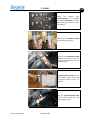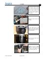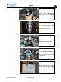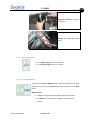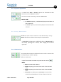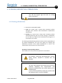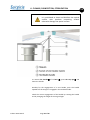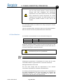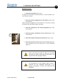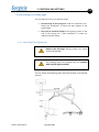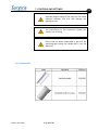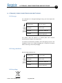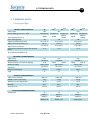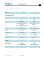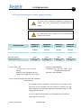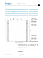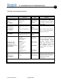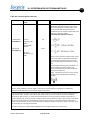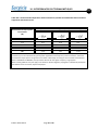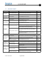
1
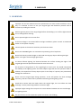
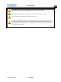
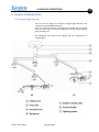
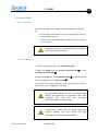
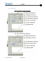
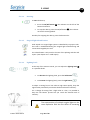
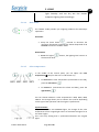
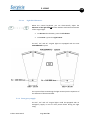
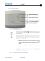
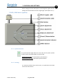
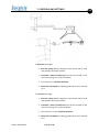
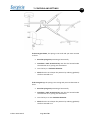
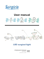
User manual LED surgical light Edition 2012 March Page 1 of 59 GB Summary 1. LEGAL INFORMATIONS: ................................................................................................................... 4 1.1. Copyright, translation and property: ....................................................................................... 4 1.2. Staff competencies: ................................................................................................................. 4 1.2.1. Operating staff: ............................................................................................................... 4 1.2.2. Cleaning staff: .................................................................................................................. 5 1.2.3. Technical staff: ................................................................................................................ 5 1.3. Safe operation: ........................................................................................................................ 6 1.4. Obligation of information: ....................................................................................................... 6 2. WARNINGS: ..................................................................................................................................... 7 3. GENERALITIES: ................................................................................................................................. 9 4. 5. 3.1. Symbols: .................................................................................................................................. 9 3.2. Concerned products: ............................................................................................................. 10 3.3. Manufacturer: ....................................................................................................................... 11 3.4. After sale service: .................................................................................................................. 11 3.5. Concerning the product use: ................................................................................................. 11 3.6. Concerning this manual: ........................................................................................................ 11 PRODUCT DESCRIPTION: ............................................................................................................... 13 4.1. Surgical light system: ............................................................................................................. 13 4.2. Surgical light: ......................................................................................................................... 15 Using: ............................................................................................................................................. 17 5.1. Surgical light: ......................................................................................................................... 18 5.1.1. First start: ...................................................................................................................... 18 5.1.2. Positioning: .................................................................................................................... 18 5.1.3. Light setting: .................................................................................................................. 19 5.1.3.1. Starting: ......................................................................................................................... 20 5.1.3.2. Surgical light identification: ........................................................................................... 20 5.1.3.3. Lighting level: ................................................................................................................. 20 5.1.3.4. Endo mode: ................................................................................................................... 21 5.1.3.5. Color temperature: ........................................................................................................ 21 5.1.3.6. Light field diameter: ...................................................................................................... 22 5.1.4. Emergency supply: ........................................................................................................ 22 5.1.5. Wall report (option): ..................................................................................................... 24 5.1.5.1. Surgical light selection: .................................................................................................. 24 Edition 2012 March Page 2 of 59 GB 5.1.5.2. Adjustment of the surgical light setting: ....................................................................... 24 5.2. 6. HD / HR Camera (option): ...................................................................................................... 25 5.2.1. Synchronization: ............................................................................................................ 25 5.2.2. Starting: ......................................................................................................................... 25 5.2.3. Camera dismount: ......................................................................................................... 29 5.2.4. Zoom adjustment: ......................................................................................................... 30 5.2.5. Focus adjustment: ......................................................................................................... 30 5.2.6. Exposure adjustment:.................................................................................................... 31 5.2.7. Preset / Memorization: ................................................................................................. 31 5.2.8. White balance: .............................................................................................................. 31 CLEANING, DISINFECTION, STERILIZATION: .................................................................................. 32 6.1. Cleaning, disinfection: ........................................................................................................... 32 6.2. Sterilization: ........................................................................................................................... 34 7. CONTROLS AND SETTINGS: ........................................................................................................... 35 7.1. Controls: ................................................................................................................................ 35 7.2. Arm setting of a ceiling light: ................................................................................................. 37 7.2.1. Balancing of the spring arm:.......................................................................................... 37 7.2.2. Travel in maximum height: ............................................................................................ 38 7.3. 7.3.1. Balancing of the spring arm:.......................................................................................... 40 7.3.2. Travel in maximum height: ............................................................................................ 42 7.4. 8. Front arm setting: .................................................................................................................. 40 Consumable: .......................................................................................................................... 43 STORAGE, USING CONDITIONS AND RECYCLING: ......................................................................... 44 8.1. Storage: ................................................................................................................................. 44 8.2. Using condition: ..................................................................................................................... 44 8.3. Recycling: ............................................................................................................................... 44 TECHNICAL DATA: .......................................................................................................................... 46 9. 9.1. Surgical light .......................................................................................................................... 46 9.2. Cameratechnical data (option): ............................................................................................. 47 9.3. Wall report (option): ............................................................................................................. 48 9.4. Emergiled emergency power supply (option): ...................................................................... 49 10. INTERFERANCES ELECTROMAGNETIQUES : .............................................................................. 51 11. FAILURES CHART: ....................................................................................................................... 56 12. COMPLIANCE CERTIFICATE: ....................................................................................................... 58 13. WARRANTY: ............................................................................................................................... 59 Edition 2012 March Page 3 of 59 1. LEGAL INFORMATIONS 1. LEGALINFORMATIONS: 1.1.Copyright,translationandproperty: SURGIRIS is the author of the documents distributed and profit from its creation, and as such owns the exclusive intellectual property right for them. Persons authorized by SURGIRIS to translate, adapt, transform or reproduce these documents, enjoy the same protection, without prejudice to the copyright of the original document. Any representation, translation, adaptation, arrangement, transformation or reproduction in full or part by electronic or magnetic means without the express consent of SURGIRIS is illegal. Only the French version shall prevail in case of problems with translation into other languages. SURGIRIS reserves the right to modify the content of this document without notice as and when required to incorporate technical product developments and updates. The trademarks mentioned in this document are the property of SURGIRIS. 1.2.Staffcompetencies: 1.2.1. Operatingstaff: The surgical light and its operating manual are intended for medical and technical staff. These members of staff must have the proper knowledge to use and maintain the surgical light in accordance with the requirements in the country where the surgical light is used. Staff using the device must be familiar with this manual for safe use. The owner can only switch on the lights if SURGIRIS or its authorized representatives have performed a functional test of the lights at the installation place, and have completed training for nursing staff users Edition 2012 March Page 4 of 59 GB 1. LEGAL INFORMATIONS of the light in accord with the operator’s manual instructions on safety. 1.2.2. Cleaningstaff: The surgical light and its operating manual are intended for medical and technical staff. These members of staff must have the proper knowledge to use and maintain the surgical light in accordance with the requirements in the country where the surgical light is used. The cleaning should be performed by personnel trained accordingly. 1.2.3. Technicalstaff: The surgical light and its operating manual are intended for medical and technical staff. These members of staff must have the proper knowledge to use and maintain the surgical light in accordance with the requirements in the country where the surgical light is used. Any corrective and preventative maintenance including calibration and adjustments must be performed by qualified technical personnel only. Edition 2012 March Page 5 of 59 GB 1. LEGAL INFORMATIONS 1.3.Safeoperation: The owner can only switch on the lights if SURGIRIS or its authorized representatives have performed a functional test of the lights at the installation place, and have completed training for nursing staff users of the light in accord with the operator’s manual instructions on safety. The warranty becomes void should the user or any third party attempt to perform any maintenance procedures without the written consent of SURGIRIS or should they not use original spare parts. SURGIRIS prohibits any modification of the lighting system made by the user or by third parties. Only SURGIRIS or an authorized representative may make changes to the product. SURGIRIS will not be liable for damages caused by the lighting system if it has been subject to alterations or repairs made by the user or any third parties without the written consent of SURGIRIS or if the light has been misused or abused or used for any purpose other than the identified use. 1.4.Obligationofinformation: It is necessary to keep this manual as a source of information for queries relative to the use, maintenance or safety on the supplied product. Anyone using the product should be able to access to the manual at any time. Edition 2012 March Page 6 of 59 GB 2. WARNINGS 2. WARNINGS: Improper use and non observance of the precautions can cause serious accidents. That is why it is essential to learn to use your surgical light and familiarize yourself with its functions by reading this manual. Remove general power of the surgical light before dismantling it; turn off the light and wait for its cooling before cleaning. Do not operate lights near a water flow. If the line voltage is not known before the light installation, please consult an authorized dealer or local power company. Connect power to the earth to avoid any risk of electric shock. Do not use SURGIRIS lights in an environment presenting risks of explosion. Never look directly inside the light on and avoid inserting any object reflecting the light beam: risk of glare from the high light output. To ensure efficient lighting, the distance between the surface emitting the light of the surgical light and the operative field must be more than 50 cm. Do not place or hang objects on the surgical light or on the arm. This would compromise the stability of the lighting system and these objects might fall onto the operation field. In addition, the suspension of heavy objects (such as the body of a person) can permanently damage the mechanism. Never cover the surgical light during operation, as this will prevent the heat exchange necessary, and thus could result in possible overheating of the lighting system. Avoid direct contact with the hands above the surgical light, this area allows the heat exchange. Use the positioning handles to move the light. Improper height setting of the stop arm can cause collisions between the arm and damage the lighting system. Any intervention on the suspension system can cause a risk of falling. Edition 2012 March Page 7 of 59 GB 2. WARNINGS Do not discard all or any part of the lighting system even if it is defective. Before any surgical operation, check the condition of the sterilizable handle. The sterilization of the handle is prohibited to warm air. The using of the handle is strictly reserved for nursing staff that completed the disinfection requirements. Any staff who have not satisfied these requirements would compromise aseptic conditions of the handle. This staff member must use the position handles located on each side of the module. Edition 2012 March Page 8 of 59 GB 3. GENERALITIES 3. GENERALITIES: 3.1.Symbols: Edition 2012 March Page 9 of 59 GB 3. GENERALITIES GB 3.2.Concernedproducts: This manual is for users of: X2 Edition 2012 March Page 10 of 59 3. GENERALITIES X1 HR / HD camera (option) In versions: Ceiling version Wall version Mobile version 3.3.Manufacturer: SURGIRIS SAS 80 rue de la Gare 59170 CROIX ‐ FRANCE Tel: (+33) 3 20 16 07 93 Fax: (+33) 3 20 95 40 19 E‐mail: [email protected] Internet: www.surgiris.com 3.4.Aftersaleservice: If you have technical questions or need replacement parts, contact us at the following coordinates: SURGIRIS SAS 80 rue de la Gare 59170 CROIX ‐ FRANCE Tel: (+33) 3 20 16 07 93 Fax: (+33) 3 20 95 40 19 E‐mail: [email protected] Internet: www.surgiris.com 3.5.Concerningtheproductuse: The X1‐X2‐X3® lights are surgical lights which allow the local lighting of the patient body. They can be used as principal light with or without integrated emergency power supply back‐up in case of a power failure, or as secondary light (Emergency light) with or without integrated emergency power supply back‐up in case of a power failure . They are intended to be used in operating theatre to provide local lighting of the patient in order to facilitate treatment and diagnosis interventions. 3.6.Concerningthismanual: Edition 2012 March Page 11 of 59 GB 3. GENERALITIES This manual aims to provide a detailed description of the correct use of the surgical light. Read it carefully to familiarize yourself with the use and operation of your device before using it in the operating theatre. All checks must be performed by technicians trained by SURGIRIS and the equipment use must conform to the purpose for which it is intended. SURGIRIS assumes no responsibility for damages due to misuse of the product. To ensure reliable and sustainable use of the light, only original spare parts supplied by SURGIRIS may be used. The company SURGIRIS would be liable for the consequences on safety, reliability and performance of the device if only the following conditions are complied with: The installation and the After Sales Service were performed by SURGIRIS or by an SURGIRIS authorized service centre or technician. The device is used according to instructions. SURGIRIS products are quality products manufactured according to approved technical standards. They left the factory in perfect working order and meet with all the required safety standards. In order to ensure a lifetime of trouble‐free use it is vital to perform an annual preventive maintenance and verification of wearing parts of the lights. This must be performed by SURGIRIS or by a SURGIRIS authorized service centre or technician. Improper use and non‐observance of precautions can cause serious accidents. Therefore it is essential to learn how to use your SURGIRIS lighting and familiarize yourself with its functions by reading this manual. Edition 2012 March Page 12 of 59 GB 4. PRODUCT DESCRIPTION GB 4. PRODUCTDESCRIPTION: 4.1.Surgicallightsystem: X3®, X2® and X1® lights are innovative surgical lights based on the new patented FOCUSMATIC© optics. They are made of aluminum for good heat exchange and are viewed from an open body for proper integration into operating theaters with a blasting cap. No phthalates was used for the design and the manufacture of surgical lights. Edition 2012 March Page 13 of 59 4. PRODUCT DESCRIPTION Others configurations available: The lighting system is secured to the ceiling with a drop tube integral with the roof and the concrete fixation kit is concealed by a ceiling cover . The drop tube adjusts the height of surgical lights from the floor of the theatre. The handling is facilitated by an extension arm associated with a spring arm , offering a wide range of mobility in the horizontal and vertical. The joints drop tube / extension arm , extension arm / spring arm and spring arm / yoke allow rotations completely free with no angle restriction. X3®, X2® and X1® surgical light is secured by a double yoke . This system provides to the light high mobility and maneuverability and comfortable use. Edition 2012 March Page 14 of 59 GB 4. PRODUCT DESCRIPTION GB 4.2.Surgicallight: The combination of red, cyan and white LEDs provides adjustment in color temperature from 3500°K to 5000°K in maintaining a CRI (Color Rending Index) above 95. Edition 2012 March Page 15 of 59 4. PRODUCT DESCRIPTION The X3®, X2® and X1® surgical light can be manipulated thanks to the sterilizable handle or with the lateral positioning handle located on each module. So you can choose the angle or the best position. The use of the sterile handle is strictly reserved for nursing staff that completed the disinfection requirements. Any staff member who has not satisfied these requirements would compromise the aseptic conditions of the handle. This staff member must use the position handles located on each side of the module. Edition 2012 March Page 16 of 59 GB 5. USING 5. Using: Do not use the X1 and X2 surgical lights in a MRI room The superposition of multiple surgical lights on the same operative field has the effect of increasing light intensity and can dry out the tissues. Adapt the lighting level accordingly. Do not use the light near a water flow. Do not use SURGIRIS lights in an environment presenting risks of explosion. Never look directly inside the light on and avoid inserting any object reflecting the light beam: risk of glare from the high light output. Edition 2012 March Page 17 of 59 GB 5. USING 5.1.Surgicallight: 5.1.1. Firststart: The owner can switch on the lights if the manufacturer or supplier has: Performed an operational test of the surgical light system at the installation location, Trained user of the surgical light according to the instructions in the manual. Improper use and non observance of precautions can cause serious accidents. 5.1.2. Positioning: 1. Position the surgical light in the middle of the field. 2. Adjust the height with the handle of prepositioning or with sterilizable central handle. 3. Adjust the angle with the sterilizable handle or with the lateral positioning handles on each side module. The position of the lamps depends on the operation type and user preferences. This is a suggestion of settings. The sterilizable handle can only be manipulated during the operation by personnel that have complied with and met the necessary recommendations of sterilization. Avoid direct contact with the hands above the surgical lighting, this area allows the heat exchange. Use the positioning handles. Edition 2012 March Page 18 of 59 GB 5. USING GB 5.1.3. Lightsetting: X3COLOR and X2COLOR control keyboard X3FIX, X2FIX and X1 control keyboard Edition 2012 March Page 19 of 59 5. USING GB 5.1.3.1. Starting: To start the device, Press the On/Off button , the indicator on the left of the button illuminates. To stop the device, press the On/Off button, the indicator on the left is extinguished. Similarly for stopping the device, press this button also. 5.1.3.2. Surgicallightidentification: Each cupola in a surgical light system is identified by its proper color. This color is established during the surgical light manufacturing and cannot be changed by the user. This identification is only used in the case of the piloting with the wall report. (See chapter 5.1.5. Wall report). 5.1.3.3. Lightinglevel: At the top of the remote control, you can adjust the lighting level to 7 possible levels. To decrease the lighting level, press the left button To increase the lighting level, press the right button . . To adjust a setting from a low value to high value quickly, keep the right button pressed till you achieve the desired level of intensity. For a change of setting from a high value to a low, it is possible to keep the left button pressed till you reach the desired level of intensity. The superposition of multiple surgical lights on the same operative field has the effect of increasing Edition 2012 March Page 20 of 59 5. USING GB light intensity and can dry out the tissues. Adapt the lighting level accordingly. 5.1.3.4. Endomode: The “ENDO” mode provides you a lighting ambience for endoscopic operations. Activation: Keep the lower button pressed to decrease the minimum illumination and keep the button depressed for 3 seconds to enter the “ENDO” mode. Deactivation: Press the higher the minimum level. button, the lighting level returns to 5.1.3.5. Colortemperature: In the middle of the control panel, you can adjust the color temperature (Only for the X3COLOR and the X2COLOR). To decrease the color temperature (accentuates to the red), press the left button . To increase it (accentuates the white and blue), press the right button . You can choose between 4 color temperatures: 3500, 4000, 4500, 5000°K. This change allows you to enhance the contrast depending on the type of the operation and the surgeon’s preferences. Synchronization: If you have at least two SURGIRIS lights, the change of the color temperature of one surgical light causes an automatic change of it on the other’s lights. This is the only setting that is synchronized between the surgical lights. Edition 2012 March Page 21 of 59 5. USING 5.1.3.6. Lightfielddiameter: Below the control keyboard, you can electronically adjust the diameter of the light fieldand this without mechanical movement of the surgical light. To decrease the diameter, press the left button. To increase it, press the right button. The X3®, X2® and X1® surgical lights are equipped with the new FOCUSMATIC© system. This system allows maintaining the light intensity level irrespective of the diameter of illuminated field. 5.1.4. Emergencysupply: The X3®, X2® and X1® surgical lights could be equipped with an emergency supply in case of main power failure during the light using. Edition 2012 March Page 22 of 59 GB 5. USING Transition to the emergency supply is automatic and is symbolized by the intermittent lighting of the battery symbol. Edition 2012 March Page 23 of 59 GB 5. USING GB 5.1.5. Wallreport(option): 5.1.5.1. Surgicallightselection: The selection of the surgical light is available if you have one or many SURGIRIS lights equipped with a wall report. This is only active on the wall report. Each lighting operation is identified by a color. This identification is determined during the surgical light manufacturing and cannot be changed. Thus the surgical lights can be controlled by the wall report due to a wireless connection. Select the surgical light that you want controlled on the wall report with the identification by color by pressing the button. Change the settings as mentioned previously from the wall report until you have desired settings. This system allows you to adjust and control the settings of your surgical lights without direct intervention on the surgical light avoiding any aseptic compromise. 5.1.5.2. Adjustmentofthesurgicallightsetting: Edition 2012 March Page 24 of 59 7. CONTROLS AND SETTINGS GB All the settings from the wall report are unchanged in regard with the settings of the control box on each surgical light. (See chapter 5.1.3.) 5.2.HD/HRCamera(option): 5.2.1. Synchronization: The synchronization light informs the user that all the system (camera remote control and surgical light) is synchronized. Flashing green light: non‐operational synchronization. Continuous green light: operational synchronization. 5.2.2. Starting: It is necessary, before every camera start, to synchronize the remote control with the camera. Edition 2011 May Page 25 of 59 5. USING GB Check the surgical light synchronization by changing the color temperature of one light causing the variation of the second one. Remove the sterilizable handle by pushing the stop pin. Remove the sterilizable handle socket by pushing the stop pin, showing the connection for the camera system. Plug the remote control on the main power supply and press the on/off switch on the “1” position. Plug the synchronization cable of the remote control on the surgical light socket. Edition 2012 March Page 26 of 59 5. USING GB Connecting the remote control to the camera socket of the surgical light, the SYNCHRO light flashes and turns on permanently and other lights to indicate that the system is synchronized. Unplug the remote control and turn off it. Turn the upper part of the camera in the “open padlock” position (to the left) until it is in the locked position. Align the security button with the open padlock. Interlock the camera by firmly holding the surgical light with one hand and holding the camera with the other one. Edition 2012 March Page 27 of 59 5. USING GB Turn the upper part of the camera in the “close padlock” sense (to the right) until you hear a click. Check the right fixation of the camera on its socket. The camera start is automatic. To adjust the image, turn the bottom part of the camera Put the sterilizable handle into position until it clicks. Check the proper engagement of the handle. When the image appears on the monitor, turn on the remote control. Edition 2012 March Page 28 of 59 5. USING GB The SYNCHRO light is flashing: Camera research. (this step can take more than 1 minute) The SYNCHRO light is turn off: Camera in connection with the remote control, the other setting lights turn on. 5.2.3. Cameradismount: Turn off the remote control and unplug it. Remove the sterilizable handle. Turn the upper part of the camera in the “open padlock” position (to the left) maintaining it firmly. Edition 2012 March Page 29 of 59 5. USING GB Unplug the camera by pressing the stop pin. Interlock the sterilizable handle socket. 5.2.4. Zoomadjustment: For a tight framing, press the + button For a large framing, press the ‐ button 5.2.5. Focusadjustment: To switch from Auto to Manual mode, maintain the F button until the indicator turns on. Press one time briefly the F button to pass to Auto mode. Manual mode: To focus, keep pressing the F button and press + button. ‐ To defocus, keep pressing the F button and press the button. Edition 2012 March Page 30 of 59 5. USING GB 5.2.6. Exposureadjustment: To switch from Auto to Manual, depress the E button until the illumination of the “Manual” indicator. Press the E button once briefly to switch to Auto mode. Manual mode: To increase exposure, simultaneously depress the button E and the + button. To reduce exposure, simultaneously depress button E and the – button. 5.2.7. Preset/Memorization: Preset: this mode restores the device to the default factory settings. Memo: This function allows memorizing the set parameters. To memorize the adjustment established, select the Memo mode by first briefly pressing the P button, then keeping the P button depressed. 5.2.8. Whitebalance: The white balance allows to calibrate the sensor and to correct color cast depending on ambient lighting. Different modes exist: To pass from a mode to another one, press one time on the button. Edition 2012 March Auto: automatic white balance. 3400°K: adjusting the white balance with a dominant red color. 5600°K: adjusting the white balance with a dominant blue color. One push: Press the button to memorize the state of the white balance depending on the type of light at the time. Page 31 of 59 6. CLEANIG, DISINFECTION, STERILIZATION 6. CLEANING,DISINFECTION,STERILIZATION: Turn off the surgical light and wait its cooling before cleaning it. 6.1.Cleaning,disinfection: Remove the sterilizable handles. Clean the system with a damp cloth containing surface detergent that conforms with manufacturer requirements and protocol. Disinfect the system with a damp cloth containing surface disinfectantensuring that the correct dosage in maintained. Do not allow any liquid to be introduced into the light or in the support arm system. The cleaning and disinfecting protocol remains to the responsibility of the health establishment, the user must follow the cleaning and disinfection protocols of his health establishment as well as the requirements and protocol of the manufacturer. Example of recommended products: Anios DDSH, Anios TSA, Surfa’safe, Wip’anios and Surfanios All products containing glutaraldehyde, phenol, iodine, bleach, alcohol or chloride ions are avoided. The user must employ and respect these previous products following the requirements and protocols established by the health experts of its establishment. In case of biocompatibility doubt of a product with the lighting system, contact SURGIRIS. Edition 2012 March Page 32 of 59 GB 6. CLEANIG, DISINFECTION, STERILIZATION It is prohibited to clean and disinfect the optical surface with products containing alcohol otherwise damage the optical surface. To remove the handle of its base , press the stop pin and lower the handle. Similarly for the engagement of a new handle, push the handle upwards till the stop pin is engaged in the window handle. Check the correct engagement of the handle by rotating the handle and by changing the height of the surgical light. Edition 2012 March Page 33 of 59 GB 6. CLEANIG, DISINFECTION, STERILIZATION The use of the sterile handle is strictly reserved for nursing staff that completed the disinfection requirements. Any staff member who has not satisfied these requirements would compromise the aseptic conditions of the handle. This staff member must use the position handles located on each side of the module. The sterilizable handles are made from an alloy of polymers resistant to heat and shocks. Clean the handles before sterilization with non‐chlorinated products. Rinse to remove all traces of product before the sterilization. 6.2.Sterilization: The handles are autoclavable. The recommended settings are: France USA Other countries 134°C during 18 min 132-135°C during 10 min, 16 min of drying Comply with regulatory requirements of countries. During the autoclave loading, make sure that the open part of the handle is pointing down. The handles should not touch other items or accessories during the sterilization process. Sterilization by hot air is prohibited. NOTE: The sterilizable handles are subject to natural wear. Following the parameters of sterilization for France and the USA, sterilizable handles are guaranteed for a minimum of 350 uses. Damaged should be not be used. The user must comply with the requirements of the national commission responsible for sanitation and disinfection. The cleaning and disinfecting protocol remains to the responsibility of the health establishment, the user must follow the cleaning and disinfection protocols of his health establishment as well as the requirements and protocol of the manufacturer. Edition 2012 March Page 34 of 59 GB 7. CONTROLS AND SETTINGS 7. CONTROLSANDSETTINGS: Disconnect general power before dismounting the surgical light. 7.1.Controls: Visual control: Check the condition of the optical surface. (before each intervention) If it is damaged or broken, debris may fall. In this case, turn off the lights and do not use it again until it is repaired. Check the operation of the surgical light.(each morning, before the beginning of the surgical program) Turn on the surgical light and check its good operation during the adjustment of settings. Also check the surgical lights synchronization in the same room. Check the operation of all the LEDS. Check the wear condition of sterilizable handles.(before each intervention) They cannot be used in case of advanced wear. (They are guaranteed for at least 350 cycles) Edition 2012 March Page 35 of 59 GB 7. CONTROLS AND SETTINGS Mechanical control: Check the arm brakes.(every year) The lights must be able to hold the position. In case of problem, see “arm settings” chapter. Check the proper engagement of the handle. (before each intervention) Check the proper engagement of the handle on its socket by rotating the handle and altering the height of the light. Check the operation of the control keyboard.(before each intervention) Check the proper attachment of the camera.(before each intervention) Check the proper balancing of the spring arm. (every year) Check the presence of the screw on the security ring (every year) holding the key at the spring arm / yoke articulation (photo 1). 1 Never look directly inside the light on and avoid inserting any object reflecting the light beam: risk of glare from the high light output. All intervention on the surgical light system is reserved for the SURGIRIS technicians or to persons competent, trained and authorized by SURGIRIS. Edition 2012 March Page 36 of 59 GB 7. CONTROLS AND SETTINGS GB 7.2.Armsettingofaceilinglight: You can adjust the arms in 2 different points: The balancing of the spring arm under the extension arm / spring arm articulation, to allow the high stability of the surgical light The travel in maximum height of the lighting system on the side of the spring arm / yoke articulation, to avoid any collision with the ceiling. 7.2.1. Balancingofthespringarm: Respect the warnings. Spring system can cause injury and damage. The settings must be realized only on systems with surgical lights installed. You can adjust the balancing which will hold the light in the desired position. Edition 2012 March Page 37 of 59 7. CONTROLS AND SETTINGS If the arm goes down, the spring is too weak and you must increase its force. Ease the spring arm positioning it horizontally Insert a male 6 sections key into the slot located under the extension arm / spring arm articulation. Turn the key in a clockwise direction. Check that the arm maintains the position by gradually reducing the force exerted on it. If the arm goes up, the spring is too strong and you must decrease its force. Ease the spring arm positioning it horizontally Introduce a male 6 sections key into the slot located under the extension arm / spring arm articulation. Turn the key in an anti‐clockwise direction. Check that the arm keeps the position by reducing gradually the force exerted on it. 7.2.2. Travelinmaximumheight: Respect the warnings. Spring system can cause injury and damage. The settings must be adjusted only on systems with surgical lightsinstalled. You can set the travel of the light system which will limit the height of the system. Edition 2012 March Page 38 of 59 GB 7. CONTROLS AND SETTINGS To decrease the height, Ease the spring arm by applying a force down with a hand and hold the horizontal position. Introduce a male 6 sections key into the slot located on the site of the spring arm / yoke articulation Turn the key in a clockwise direction. Check the arm height by reducing gradually the force exerted on it. To increase the height, Ease the spring arm by applying a force down with a hand and hold the horizontal position. Introduce a male 6 sections key into the slot located on the site of the spring arm / yoke articulation Turn the key in an anti‐clockwise direction. Check the arm height by reducing gradually the force exerted on it. Edition 2012 March Page 39 of 59 GB 7. CONTROLS AND SETTINGS Improper height setting of the stop arm can cause collisions between the arm and damage the lighting system. Any intervention on the suspension system can cause a risk of falling. Ensure that no object suspended in space of the operating light system can collide with it. (ex: fire detector) 7.3.Frontarmsetting: If you have an arm with a front fixation, you can also adjust the brake force and the stop height. 7.3.1. Balancingofthespringarm: Respect the warnings. Spring system can cause injury and damage. The settings must be adjusted only on systems with surgical lights installed. Edition 2012 March Page 40 of 59 GB 7. CONTROLS AND SETTINGS GB If the arm goes down, the spring is too weak and you must increase its force. Ease the spring arm positioning it horizontally Introduce a male 6 sections key into the slot located under the extension arm / spring arm articulation. Turn the key in a clockwise direction. Check that the arm keeps the position by reducing gradually the force exerted on it. If the arm goes up, the spring is too strong and you must decrease its force. Ease the spring arm positioning it horizontally Introduce a male 6 sections key into the slot located under the extension arm / spring arm articulation. Turn the key in an anti‐clockwise direction. Check that the arm keeps the position by reducing gradually the force exerted on it. Edition 2012 March Page 41 of 59 7. CONTROLS AND SETTINGS GB 7.3.2. Travelinmaximumheight: Respect the warnings. Spring system can cause injury and damage. The settings must be adjusted only on systems with surgical lights installed. Remove the screws and the cover . Ease the spring arm by applying a force down with a hand until you see the adjustment nut in the opening on the side. To increase the height, place a metal rod in the adjustment openings and turn the nut down. To decrease the height, place a metal rod in the adjustment openings and turn the nut up. Check the arm height by reducing gradually the force exerted on it. Edition 2012 March Page 42 of 59 7. CONTROLS AND SETTINGS GB Improper height setting of the stop arm can cause collisions between the arm and damage the lighting system. Any intervention on the suspension system can cause a risk of falling. Ensure that no object suspended in space of the operating light system can collide with it. (ex: fire detector) 7.4.Consumable: Edition 2011 May Page 43 of 59 8. STORAGE, USING CONDITIONS AND RECYCLING 8. STORAGE,USINGCONDITIONSANDRECYCLING: 8.1.Storage: For a transport or a storage exceeding 15 days, you must respect this conditions. Temperature ‐10°C to +50°C Humidity 10% to 75% Pressure 500 hPa to 1060 hPa Altitude De 0 à 5574 m (Standard value at 500 hPa) The device must be stored in a closed place and covered. Avoid frequent changes of storage places. To avoid any condensation problems, leave the lighting system in the installation room in its closed packaging for a minimum of 2hours before removing it from the packaging. 8.2.Usingcondition: Normal using conditions are: Temperature +5°C to +40°C Humidity 30% to 75% Pressure 700 hPa to 1060 hPa Altitude De 0 to 3013 m (Standard value at 700 hPa) 8.3.Recycling: Edition 2012 March Page 44 of 59 GB 9. TECHNICAL DATA The X3®, X2® and X1® surgical lights must be discarded by appropriate and regular channels and according to the standards in effect in the country at the time of the disposal. Edition 2012 March Page 45 of 59 GB 9. TECHNICAL DATA GB 9. TECHNICALDATA: 9.1.Surgicallight X1 X2FIX X2COLOR X3FIX X3COLOR LED LED LED 100.000 Lux 150.000 Lux 160.000 Lux 160.000 Lux 160.000 Lux 3500 to 3500 to 4500K 4500K 4500K 5000K 5000K >95 >95 >95 15 to 20 cm 15 to 30 cm 15 to 32 cm 80 cm 110 cm 130 cm 5 to 100 % 5 to 100 % 5 to 100 % OPTICAL CHARACTERISTICS Light source Central lighting at 1m (+/‐ 10%) Color temperature in °K Color rending index Lighting field diameter (d10) Depth of constant field L1+L2 Light intensity variation Temperature elevation level at the surgeon head According to IEC‐60601‐2‐41 ELECTRICAL CHARACTERISTICS Light source LEDs lifetime Electrical power at maximum lighting Electrical supply Frequency Product classification Type PHYSICAL CHARACTERISTICS Light surface emitting Weight of the surgical light Diameter of the surgical light Rotation Vertical travel QUALITATIVE CHARACTERISTICS Compliance <1 °C LED >40 000 h 42 W 100 to 240 V 50 / 60 Hz Class I B 660 cm2 5 kg 30 cm 360 ° 120 cm CE 60601‐1 60601‐2 60601‐2‐41 Edition 2012 March Page 46 of 59 <1 °C <1 °C LED >40 000 h 90 W 120 W 100 to 240 V 50 / 60 Hz Class I B 1400 cm2 11 kg 64 cm 360 ° 120 cm CE 60601‐1 60601‐2 60601‐2‐41 LED >40 000 h 110 W 160 W 100 to 240 V 50 / 60 Hz Class I B 2100 cm2 15 kg 70 cm 360 ° 120 cm CE 60601‐1 60601‐2 60601‐2‐41 9. TECHNICAL DATA GB 9.2.Cameratechnicaldata(option): Capteur Image sensor Nombre de pixels Effective number of pixels Format Aspect ratio Standard vidéo Signal system Résolution Resolution Objectif Lens Focale Focal Ouverture Opening Focalisation automatique Automatic focal Sensibilité Sensibility Balance des blancs White balance Distance mini. de mise au point Minimum object distance Signal/Bruit Signal/Noise ratio Sortie Output connection Boitier de contrôle Control box Edition 2012 March Haute résolution / High resolution Haute définition / High definition CCD 3/4 CMOS 1/3" 440 000 pixels 2 000 000 pixels 4:3 16:9 PAL 1080i 530 TV Lignes N/A 36x (zoom optique) et 12x (zoom numérique) 10x (zoom optique) et 12x (zoom numérique) 36x (optical zoom) and 12x (digital 10x (optical zoom) and 12x (digital zoom) zoom) f=3,4 mm à 122,4 mm f=3,4 mm to 122,4 mm F 1,6 à F 4,5 F 1,6 to F 4,5 Auto/Manuel Auto/Manual f=5,1 mm to 51,0 mm f=5,1 mm à 51,0 mm F 1,8 à F 2,1 F 1,8 to F 2,1 Intégré Integrated 1,4 lux (F 1,6 50IRE) 1 lux (F 1,8 50IRE) Auto/Manuel Auto/Manual 320 (grand angle) à 1500mm (télé) 320 (wide) to 1500mm (tele) Auto/Manuel Auto/Manual 10 (grand angle) à 800 mm (télé) 10 (wide) to 800 mm (tele) >50 dB >50 dB 2 BNC Composite 1 S‐VHS 1 SDI ‐ sortie numérique Mobile en WCT (sans fil) Mobil with wireless WCT 1 Y/Pb/Pr 1 DVI 1 SDI ‐ sortie numérique Mobile en WCT (sans fil) Mobil with wireless WCT Page 47 of 59 9. TECHNICAL DATA GB 9.3.Wallreport(option): Power supply 100‐240V AC, 50/60Hz (by the general power supply). Or Power supply 27,3V DC, 45 mA (by the Emergiled or the power supply flange). Emergiled power supply Main power supply Flange power supply Edition 2012 March Page 48 of 59 9. TECHNICAL DATA GB 9.4.Emergiledemergencypowersupply(option): Any parts can be removed or modified. It is important to respect the part characteristics communicated by Surgiris. No replacement parts outside of parts proposed by Surgiris can be made. SPECIFICATIONS Power Output voltage Using temperature Storage temperature Maximum weight Reservation (in mm) EMERGILED MONO 1h 100‐240V AC 50/60Hz 27,3V DC 0°C to +40°C ‐10°C to +60 °C 30 kg H : 900, L : 700, P : 250 EMERGILED MONO 2h 100‐240V AC 50/60Hz 27,3V DC 0°C to +40°C ‐10°C to +60 °C 33 kg H : 900, L : 700, P : 250 EMERGILED DUO 1h 100‐240V AC 50/60Hz 27,3V DC 0°C to +40°C ‐10°C to +60 °C 36 kg H : 900, L : 700, P : 250 EMERGILED MONO 2h 100‐240V AC 50/60Hz 27,3V DC 0°C to +40°C ‐10°C to +60 °C 39 kg H : 900, L : 700, P : 250 Battery: 12V, 7,5A Reference: SAV‐LED‐0055 L x l x h (in mm) : 151 x 65 x 97,5 Cylindrical type gG HPC 500V 20A, 10x38mm (Emergiled 2h) 2,65 kg Reference: SAV‐LED‐0056 Reference: SAV‐LED‐0009 (lot of 2) Replacement suggested every 5 years Fuse: Cylindrical type gG HPC 500V 16A, 10x38mm (Emergiled 1h) The voltage presence 100‐240V is indicated by the red light on the front face of the Emergiled. The LED turned on indicates that the lights assigned to the emergency block are fed and protected in case of general power failure. In case of a general power failure, the Emergiled auto switches the power light on the battery. Edition 2012 March Page 49 of 59 9. TECHNICAL DATA GB Circuit breaker type upstream of the Emergiled Section of power cable 100‐240V Section of power cables light 27.3 V (<15m) Section of power cables light 27.3 V (_ 15m to 30m) Section of wall power cables carry 27.3 V Heat dissipation Local technical ventilation 10 A, Magnetothermic 3G 2,5 mm² 5G 6 mm² 5G 10 mm² 5G 1,5 mm² 120 W/h Naturally ventilated Two tests per year must be performed to ensure the safety operation of the emergency block: Check battery switching. Cut power of emergency block via its circuit breaker and verify that the light assigned to the block emergency lights correctly. Edition 2012 March Check the battery life. Cut power of emergency block via its circuit breaker and measure the time of illumination provided by the batteries. Page 50 of 59 10. INTERFERANCES ELECTROMAGNETIQUES 10. INTERFERANCESELECTROMAGNETIQUES: The X1‐X2‐X3 is intended for use in the electromagnetic environment in which radiated RF disturbances are controlled as specified in the following pages. The customer or the user of the X1‐ X2‐X3 should assure that it is used in such an environment and can help prevent electromagnetic interference by maintaining a minimum distance between portable and mobile RF communications equipment (transmitters) and the X1‐X2‐X3 as recommended below, according to the maximum output power of the communications equipment. Table 201 –electromagnetic emissions – Emissions test Compliance Electromagnetic environment – guidance RF emissions CISPR 11 Group 1 The X1‐X2‐X3 uses RF energy only for its internal function. Therefore, its RF emissions are very low and are not likely to cause any interference in nearby electronic equipment. RF emissions CISPR 11 Class A IEC 61000‐3‐2 Harmonic emissions IEC 61000‐3‐3 Voltage fluctuations/ flicker emissions Not applicable Not applicable Edition 2012 March Page 51 of 59 The X1‐X2‐X3 is suitable for use in all establishments other than domestic and those directly connected to the public low‐ voltage power supply network that supplies buildings used for domestic purposes. FR 10. INTERFERANCES ELECTROMAGNETIQUES Table 202 ‐ electromagnetic immunity Immunity test Electrostatic discharge (ESD) IEC 61000‐4‐2 IEC 60601‐ test level ±6 kV contact ±8 kV air Compliance level Electromagnetic environment guidance 6 kV contact 8 kV air Floors should be wood, concrete or ceramic tile. If floors are covered with synthetic material, the relative humidity should be at least 30 %. ±2 kV for power supply Electrical fast transient/burst IEC 61000‐4‐4 lines ±1 kV for input/output 2 kV Non applicable lines Surge IEC 61000‐4‐5 ±1 kV differential mode ±2 kV common mode <5 % UT (>95 % dip in UT) for 0,5 cycle Voltage dips, short interruptions and voltage variations on power supply input lines IEC 61000‐4‐11 40 % UT (60 % dip in UT) for 5 cycles 70 % UT (30 % dip in UT) for 25 cycles <5 % UT (>95 % dip in UT) for 5 sec Power frequency (50/60 Hz) magnetic field IEC 61000‐4‐8 3 A/m 1 kV 2 kV 0V / 10 ms 48V / 100ms 84 V/ 500ms 0V/ 5000ms Not applicable NOTE UT is the a.c. mains voltage prior to application of the test level. Edition 2012 March Mains power quality should be that of a typical commercial or hospital environment Page 52 of 59 Mains power quality should be that of a typical commercial or hospital environment. If the user of the X1‐X2‐X3 requires continued operation during power mains interruptions, it is recommended that the X1‐X2‐X3 be powered from an uninterruptible power supply or a battery. Power frequency magnetic fields should be at levels characteristic of a typical location in a typical commercial or hospital environment. FR 10. INTERFERANCES ELECTROMAGNETIQUES FR Table 204 –electromagnetic immunity Immunity test IEC 60601 test level Conducted RF IEC 61000‐4‐6 Radiated RF IEC 61000‐4‐3 3 Vrms 150 kHz to 80 MHz outside ISM bandsa 10 V/m 80 MHz to 2,5 GHz Compliance level 3 V 3 V/m Electromagnetic environment – guidance Portable and mobile RF communications equipment should be used no closer to any part of the X1‐X2‐X3, including cables, than the recommended separation distance calculated from the equation applicable to the frequency of the transmitter. Recommended separation distance where P is the maximum output power rating of the transmitter in watts (W) according to the transmitter manufacturer and d is the recommended separation distance in metres (m). Field strengths from fixed RF transmitters, as determined by an electromagnetic site survey,a should be less than the compliance level in each frequency range.b Interference may occur in the vicinity of equipment marked with the following symbol: NOTE 1 At 80 MHz and 800 MHz, the higher frequency range applies. NOTE 2 These guidelines may not apply in all situations. Electromagnetic propagation is affected by absorption and reflection from structures, objects and people. a )Field strengths from fixed transmitters, such as base stations for radio (cellular/cordless) telephones and land mobile radios, amateur radio, AM and FM radio broadcast and TV broadcast cannot be predicted theoretically with accuracy. To assess the electromagnetic environment due to fixed RF transmitters, an electromagnetic site survey should be considered. If the measured field strength in the location in which the X1‐X2‐X3 is used exceeds the applicable RF compliance level above, the X1‐X2‐X3 should be observed to verify normal operation. If abnormal performance is observed, additional measures may be necessary, such as reorienting or relocating the X1‐X2‐X3. b) Over the frequency range 150 kHz to 80 MHz, field strengths should be less than 3 V/m. Edition 2012 March Page 53 of 59 10. INTERFERANCES ELECTROMAGNETIQUES Edition 2012 March Page 54 of 59 FR 10. INTERFERANCES ELECTROMAGNETIQUES FR Table 206 – Recommended separation distances between portable and mobile RF communications equipment and the X1‐X2‐X3 Separation distance according to frequency of transmitter (m) Rated maximum output power of transmitter (W) 150 kHz to 80 MHz 80 MHz to 800 MHz 800 MHz to 2,5 GHz 0.01 0.04 0.06 0.12 0.1 0.11 0.18 0.37 1 0.35 0.58 1.17 10 1.11 1.84 3.69 100 3.50 5.83 11.67 For transmitters rated at a maximum output power not listed above, the recommended separation distance d in metres (m) can be estimated using the equation applicable to the frequency of the transmitter, where P is the maximum output power rating of the transmitter in watts (W) according to the transmitter manufacturer. NOTE 1 At 80 MHz and 800 MHz, the separation distance for the higher frequency range applies. NOTE 2 These guidelines may not apply in all situations. Electromagnetic propagation is affected by absorption and reflection from structures, objects and people. Edition 2012 March Page 55 of 59 11. FAILURE CHART GB 11. FAILURESCHART: Problem Probable cause(s) Action(s) to conduct Chapter Electric network problem Check the electrical supply and the fuses 6.3.1. Control problem Call the SURGIRIS technical service 6.3.1. Control problem Call the SURGIRIS technical service 6.3.1. Utilization problem See "Light setting" chapter 6.3.3. Control problem Call the SURGIRIS technical service 6.3.3. Identification problem of the light See "Light setting" chapter 6.3.7. The light does not turn on The light does not turn off The"ENDO" mode does not turn on The wall report does not work Communication problem of Call the SURGIRIS technical service the wall report with the lights 6.3.7. Some LEDs do not work depending on the light settings 6.3.2. Vary the settings to check their good working 6.3.2. If the number of damaged LEDs is low, you can use the device normally thanks to compensation system with the other LEDs 6.3.2. If the number of damaged LEDs is important, call the SURGIRIS technical service 6.3.2. Normal working of the light Some LEDs do not light on Working problem of the LEDs Arm overloaded The light system Setting problem of the arm does not hold brakes the position Fixing problem of the arms to the roof or roof problem Left in suspension, only the devices installed by SURGIRIS The sterile Utilization problem handle does not break away from Mechanism problem its base See " Cleaning, Disinfection and Maintenance " chapter 7.1. Check the mechanism of it 7.1. Change the handle 7.1. See "Cleaning, Disinfection and Maintenance" chapter 7.1. Check the mechanism of it 7.1. Change the handle See “Cleaning and disinfection» chapter to know the sterilization temperatures recommended 7.1. Utilization problem The sterile handle does not Mechanism problem fit on its base Problem of the sterilization temperature and/or wear Edition 2012 March 8.1 Set the brake like in the "Brake setting" chapter 8.2.1. / 8.3.1. Call the SURGIRIS technical service 8.2.1. / 8.3.1. Page 56 of 59 7.1. / 7.2. 11. FAILURE CHART GB See "Cleaning, Disinfection and Maintenance" chapter to know the sterilization temperature recommended Edition 2012 March Page 57 of 59 7.1. 12. COMPLIANCE CERTIFICATE 12. COMPLIANCECERTIFICATE: Edition 2012 March Page 58 of 59 GB 13. WARRANTY 13. WARRANTY: SURGIRIS guarantees the equipment against component or manufacture faults for 18 months from the date of receipt and no later than 24 months after delivery to contract terms. The warranty covers only new supplies that are manufactured by SURGIRIS. It is limited to replacement parts recognized to be defective. The cost of labor, accommodation, travel and insurance of the personnel performing the parts replacement are all charged to the customer. All parts replaced will become the property of SURGIRIS and must be returned to it within one month after its replacement, otherwise SURGIRIS reserves the right to charge the value of the replaced part to the customer. The interventions done under warranty do not extend the original warranty period. This warranty does not apply to normal wear parts and consumables. To profit by the warranty, the buyer must notify by letter or telex confirmed by letter, of any defects within 3 days at the latest after its establishment. The buyer must submit to SURGIRIS all evidence demonstrating that the failure lies with SURGIRIS and give all easiness to SURGIRIS to proceed to their establishments. SURGIRIS advises the purchase of spare parts that may have to be fitted to the unit. SURGIRIS can use existing spare parts from the purchaser subject to replace it. The warranty ceases if the supplies have been modified or repaired made by the buyers or any third party without the prior written consent of SURGIRIS. This warranty excludes any compensation payment. The engagements of that warranty are personal to the buyer and cease as soon as it sells. The warranty does not cover: The incidents relating to fortuitous or force majeure events described in article XI, The repairs or replacements required by normal wear of the equipment, The damages or accidents proceeding from the purchaser fact such as negligence, lack of supervision, error Note: The repairs or settings must be made by SURGIRIS or his authorized representative. In case of one of the SURGIRIS representative is in charge of repairs, the user must obtain a detailed report of the agent explaining the repairs effected. This report must include the technical data concerning the repairs and be signed by the certified company and the user. When the repairs are not made by SURGIRIS, the modified parts must be reported on behalf of the repair company. Edition 2012 March Page 59 of 59 GB