1
PROGRAMMING MX2
Parameter
Parameter name
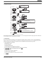
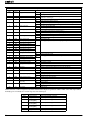
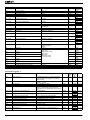
b022
Torque limit 2 (rev/regen.)
Description
Torque limit level in reverse regen. quadrant, range is 0 to 200% / no(disabled)
b043
Torque limit 3 (rev/power)
Torque limit level in reverse powering quadrant, range is 0 to 200% / no(disabled)
b044
Torque limit 4 (fwd/regen.)
Torque limit level in forward regen. quadrant, range is 0 to 200% / no(disabled)
b045
Torque LAD STOP selection
00
01
Disable
Enable
100% torque is referred to inverter rated current, absolute torque value is up the motor to be combined.
3.17 Torque control
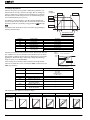
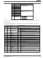
Torque control in open loop could be achieve with following parameters. 100% torque is referred to inverter rated current but
absolute torque value depends on the motor connected. It has limited accuracy and working range so is recomended only above
15 - 20Hz and over 20 - 30% of the motor torque capacity.
Parameter
P033
Parameter name
Torque command input selection
Description
00… Analog voltage input [O]
01… Analog current input [OI]
03… Operator, 06…Option
P034
Torque command level input
Set range is 0~200%
P036
Torque bias mode selection
00… According to the sign
01… According to the rotation direction
05… Option
P037
Torque bias value setting
Range is -200~200%
P038
Torque bias polar selection
00… No bias
01… Operator
P039
Speed limit of Torque control (Forward
rotation)
Set range is 0.00~120.00Hz
P040
Speed limit of Torque control (Reverse
rotation)
Set range is 0.00~120.00Hz
P041
Speed / Torque control switching time
Set range is 0 to 1000 ms
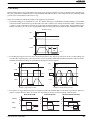
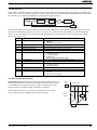
To enable the torque control is necessary to assign the “ATR” (Enable torque command input) to one of the multi-function inputs
and set it to ON. When the input is OFF the inverter will work in speed mode.
At low speed, small torque command or 4 quadrant control applications the perfomance of this function will be limited due the
open loop system.
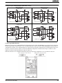
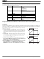
3.18 Electronic thermal overload
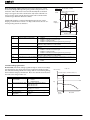
The thermal overload detection protects the inverter and motor from overheating due to an excessive load using a current
inverse time curve to determine the trip point. The characteristic curve depends on dual rate setting in b049 and is unique for
both inverter and motor but reduction rate depending on the frequency could be selected in parameter b013.
b049=00 (HD )
b049=01 (ND )
Trip time (s)
Trip time (s)
60
60
3.0
0.5
0
MX2 Quick Start Guide Draft
109% 150%
200%
Percentage of
b012/b212
0
116% 120%
150%
Percentage of
b012/b212
31