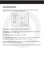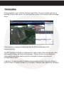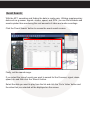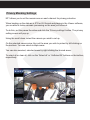
1
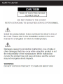
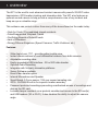
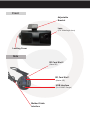
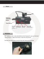
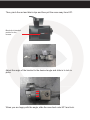
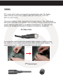
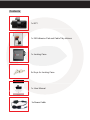
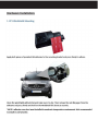
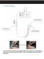
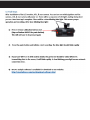
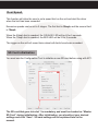
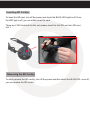
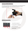
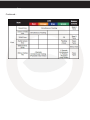
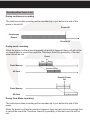
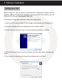
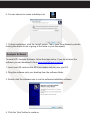
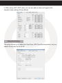
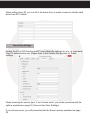
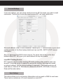
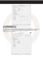
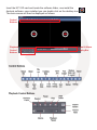
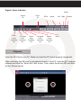
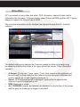
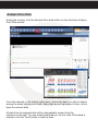
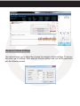
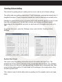
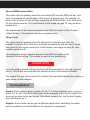
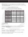
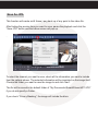
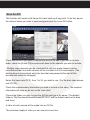
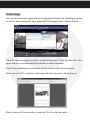
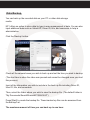
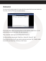
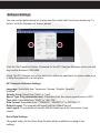
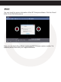
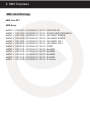
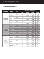
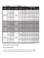
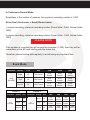
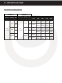
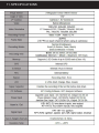
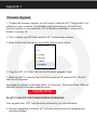
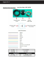
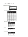
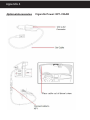
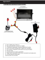
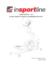
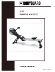
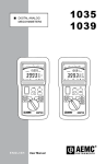
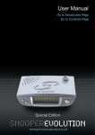
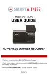
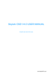
3G/WiFi Enabled Telematics
Camera for Commercial Vehicles
KP1
User Guide
v1.4
1
Table of Contents
GPS Reception .............................................................................
6
1. Overview .................................................................................
Contents ..........................................................................
7
8
2. Installation ..............................................................................
13
3. Basic Operation ......................................................................
Automatic Start ................................................................
LED Operation at Start-up ...............................................
G-Sensor Calibration .......................................................
Recording Modes ............................................................
Communication ...............................................................
Over Speed .....................................................................
SD Card Initialization .......................................................
Inserting The SD Card .....................................................
Removing The SD Card ..................................................
Inserting 3G/WiFi USB Modem .......................................
LED/Buzzer Specification ................................................
Recording When Power is Cut ........................................
18
18
18
18
19
20
21
21
22
22
23
23
26
4. Software Installation ..............................................................
Configuration Tool ...........................................................
Analysis Software ............................................................
27
27
28
5. Configuration Software .........................................................
Initialize SD Card .............................................................
Device Settings ...............................................................
Record Settings ...............................................................
Event Settings .................................................................
Information Settings ........................................................
Connectivity Settings .......................................................
Email Setup Settings ......................................................
User Setup Settings
...................................................................
Server Settings ................................................................
30
30
31
33
36
37
38
39
39
40
Table of Contents
6. Analysis Software ....................................................................
41
Playback ..............................................................................
Open Files ...........................................................................
42
43
Drive Data ............................................................................
Analyze Drive Data ...............................................................
44
45
Analysis Criteria Settings ......................................................
Grading Criteria Setting ........................................................
Grading Method ...................................................................
Graph Display Setting ...........................................................
Tracking Map ........................................................................
Event Search .........................................................................
Privacy Settings .....................................................................
Save As JPG ...........................................................................
Save As AVI ...........................................................................
Print Image ...........................................................................
Backup ..................................................................................
Backup List ............................................................................
47
49
52
54
55
56
57
58
59
60
61
62
Software Settings .................................................................. 63
About .................................................................................... 64
7. Notification Email Templates .................................................... 65
Alert Message ....................................................................... 65
Event Notification .................................................................
Daily Report ..........................................................................
8. Email Alerts ..............................................................................
Emailing KP1 ........................................................................
Request Original Data ..........................................................
Request System Info ............................................................
Request Preview ..................................................................
Remote Configure ................................................................
9. SMS Templates .............................................................................
66
67
68
68
68
69
70
70
71
SMS: Alert Message ..............................................................
72
Table ofCONTINUED...
Contents
10. Recording Storage Times ........................................................
73
Continuous Mode ................................................................
Event Mode .........................................................................
73
75
Dual Mode …………….............................................................
11. Technical Specs ......................................................................
76
77
Appendix
......................................................................................
Firmware Upgrade ................................................................
Optional Accessories - Power Adaptor (INT1-S)....................
Optional Accessories - Junction Box (INT2)...........................
Optional Accessories - Cigarette Power ...............................
Optional Accessories - LCD Monitor …………………………………
..........................................................
78
79
80
81
82
83
SAFETY ADVICE
Table of Contents
GPS RECEPTION Table of Contents
1. Activate the product in an area with a clear view of the sky &
without large buildings to improve GPS reception.
For commercial purposes GPS has an average range error of more than 15 meters
and the range error could be more than 100 meters depending on environmental
conditions like buildings and roadside trees etc.
2. The temperature range for optimum operation of the GPS receiver in
your car is -10 ~ 50°C.
3. When using the product for the first time or after a long period (more than
three days), it may take a little longer to recognize your current location.
It may take between five and thirty minutes to get GPS reception.
GPS reception may be impaired under the following circumstances:
1) If there is an object at the end of the GPS antenna.
2) If your vehicle has metallic elements on or in the windshield.
3) If equipment generating electromagnetic waves that interfere with the GPS signal
are installed in the vehicle e.g. other GPS devices including certain types of
wireless activated alarms, MP3 and CD players and camera alarms using GPS.
4) If you are using a receiver connected by a cable, electrical interference can
be avoided by simply changing the location of the KP1 installation.
5) On heavily overcast or cloudy days, if the vehicle is in a covered location such as
under a bridge or raised roadway, in a tunnel, an underground roadway or parking
area, inside a building or surrounded by high-rise buildings.
6) If GPS signal reception is poor, it may take longer to locate your current position
when the vehicle is moving than when it is stationary.
1. OVERVIEW
The KP1 is the world’s most advanced incident camera with powerful 3G/WiFi video
transmission, GPS location tracking and telematics data. The KP1 also features an
optional second camera to help provide a comprehensive view of any incident and
keep an eye on valuable cargo.
This evidence can protect a driver from many of the issues faced on the roads today:
• Cash for Crash / Pre-meditated staged accidents
• False/Exaggerated Whiplash Claims
• Conflicting Reports of Actual Events
• Lack of Witnesses
• Driving Offence Allegations (Speed Cameras, Traffic Violations, etc.)
Features:
•
•
•
•
•
•
•
•
•
•
•
•
•
Wide Angle Lens: 170° - providing pillar-to-pillar view
Instant remote retrieval of court admissible evidence from both cameras
Adjustable recording rates
Easily upgradable USB interface - 3G or WiFi data transfer
Optional Audio Recording
Integrates with 3rd party telematics platforms
Server Software available
Email Video transfer option
Internal Microphone and Speaker
Smart Bosch G-Force sensor, 100x per second sampling rate
GPS + GLONASS built-in for superior location accuracy
Password protected recordings preventing unauthorized access of recordings and
data on the SD card
Lockable tamper resistant cover protects unauthorized access to the SD card(s)
and USB modem (3G or Wi-Fi). It also disables the ability to adjust the camera
angle.
Front
Adjustable
Bracket
Lens
(170° Wide Angle Lens)
Locking Cover
Side
SD Card Slot 2
(Slave SD)
SD Card Slot 1
(Master SD)
USB Interface
(For 3G/WiFi Dongle)
Molded Cable
Interface
Rear
GPS
G-Sensor
Calibration
Button
Panic Button
Red LED Orange LED
(Over
(Over Speed
Speed 2) 1)
Blue LED
(Record)
Green LED
(Communication)
Bracket
KP1 features a new, easily adjustable bracket designed to give you the ideal
viewing angle. To adjust the bracket, follow the steps below.
Remove the locking case using the key and turning anti-clockwise.
Then, pinch the red and black clips and then pull the case away from KP1.
Black clip in identical
position on the
reverse
Adjust the angle of the bracket to the desired angle and slide in to lock in
place.
When you are happy with the angle, slide the case back onto KP1 and lock.
Cables
KP1 comes with 2 cables permanently connected at the side. The thicker
cable connects to the power adaptor cable (KP1-PWK, KP1-CIG, KP1INT1-S, or KP1-INT2).
The second (thinner) cable connects to the second camera. This cable allows
both power and video to be carried to the secondary camera. Please note that the
second cable provides power to compatible SmartWitness “-S” cameras only
(SVA021-S, SVA025-S, SVA030-S, SVA032-S, SVA033-S, SVA041-S).
KP1 Main Cable
To connect the cable to either the cigarette lighter adaptor or either junction
box, attach by lining up the arrows on each cable and then push together. To
secure them together, twist the silver plate as shown below.
2ND Camera Input
Contents
1x KP1
1x 3M Adhesive Pad and Cable Tidy stickers
1x Locking Case
2x Keys for Locking Case
1x User Manual
2. INSTALLATION
1x Power Cable
Hardware Installation
3. BASIC OPERATION
Automatic Start
Plug the car charger cable into the cigarette lighter adaptor in your vehicle and KP1
will start automatically.
However KP1 will not start recording immediately after the power has been turned
o n . It takes around 30-45 seconds for the built-in power backup system to be
charged. After this, the internal flash memory will be ready to record.
PLEASE NOTE
Please make sure to turn off the power of the KP1 when inserting or ejecting the SD
card and the USB 3G/WiFi dongle.
LED Operation at Start-up
Firstly, the Red LED will be ON (around 6 sec), then, Red LED (Warning) and Orange
LED will be ON (around 12 sec)
Red LED, Orange LED, Blue LED, Green LED will be ON in sequence
(around 40 ~ 50 sec)
Blue LED On/Off (Starting time: around 60 ~ 70 sec)
(Buzzer sound operation at start-up)
Single “Beep” after starting (If beep is set to ‘On’ in config settings).
G-Sensor Calibration
After installing KP1, you will need to calibrate the G-Sensor. To do this, turn on KP1
and park the vehicle on a flat surface. Then, press the [G-Sensor Calibration] button
for one second.
This G-Sensor calibration is only needed the first time KP1 is used.
Recording Modes
Normal (Continuous)
This is the default and main mode for recording. In this setting the unit will begin
recording after boot up and record the entire time the unit is powered. Recording files
will be made for 10 minutes. Once a 10 minute file is made, a new file will begin and
so on. When in normal record mode, the BLUE LED will be blinking slowly to
indicate normal recording.
Event (Shock, Panic, Overspeed, & Alarm inputs)
The event recording function will be automatically started by G-sensor, panic button
or alarm. You can set the G-sensor parameters for the unit on your PC using KP1
config software.
Each event file will contain 20 seconds of footage before, and up to 20 seconds after
an incident. The event file can also be extended by a 2nd trigger during event
recordings.
When a file is extended by a second trigger, 20 seconds post recording from the
event will be added to the data file with a maximum recording time of 3 minutes. Once
the 3 minutes has been reached, the file will split and a new file will be created but the
data will be continuous.
When in event recording mode, the BLUE LED will be blinking. The buzzer will also
sound twice when the event record has been triggered (If set to ‘On’ in the config
settings).
SD Auto Format Feature (Optional)
When one of the SD Cards has an error and cannot record, all the cards will be
formatted and all data will be erased. Configuration settings will be backed up.
Dual Mode Record (Event + Continuous)
1) Using 1x SD Card
The Normal (continuous) record frame rate is 1fps and the file will be stored on the
“Normal” folder.
Event record will work according to the frame rate setting. For example, 30 frames
per second recording and the file will be stored on the “Event” folder.
2) Using 2x SD Cards
The Normal (continuous) record file (at 1FPS) will be stored on the SD slot No. 1.
The Event record file will be stored on the SD slot No.2. There will be no limit to the
frame rate when using 2 cards.
In this mode, the BLUE LED will be blinking fast and the buzzer will sound twice when
the event recording has been triggered.
PLEASE NOTE
If there are 6 ‘beeps’ sounded from the unit, this means that there is an SD card error
or the SD card is full.
Driving File Record
The DRV (Driving) file will be recorded during driving even if there are no events or
video. The DRV file consists of GPS and G-sensor data. This helps to find specific
data or driving behaviors.
The DRV file overwrites the oldest data. The DRV files will be made every 10 minutes.
Communication
The USB 3G/WiFi modem is inserted to the USB terminal inside the locking case.
For a list of compatible USB modems with KP1, please contact your local dealer.
During communication, the GREEN LED will be on to show you can communicate.
The GREEN LED will flash when communication is performed.
The dongle will need to be setup with the correct APN settings using the KP1 config
software.
If there is a communication error, the unit will ‘Beep’ twice.
If there are modem recognition errors, the unit will ‘Beep’ 3 times.
Over Speed
This function will allow the user to set a speed limit on the unit and alert the driver
when the limit has been exceeded.
Excessive speeds can be set in 2 stages. The first limit is 50mph and the second limit
is 70mph.
When the 50mph limit is reached, the ORANGE LED will be lit for 5 seconds.
When the 70mph limit is reached, the RED LED will be lit for 5 seconds.
The trigger on the unit will sound twice when both limits have been exceeded.
SD Card Initialization
You must use the Configuration Tool to initialize a new SD card before using with KP1.
TE
The SD card that goes into slot 1 is mandatory and must be checked as “Master
SD Card” during initialization. After initialization, you should set your desired
settings and click “Save”. SD card settings will be explained later in the
manual.
Inserting SD Card(s)
To insert the SD card, turn off the power and check the BLUE LED Light is off. Once
the LED light is off, you can safely insert the card.
There are 2 SD Card slots for this unit, please insert the first SD card into SD card
slot 1.
Removing the SD Card(s)
To safely remove the SD card(s), turn off the power and then check the BLUE LED, once off,
you can remove the SD card(s).
Inserting a 3G/WiFi USB Modem
Turn off the power and then check the BLUE LED light. Once the BLUE LED light is
off, insert the 3G/WiFi USB modem. Check with your distributor for a list of
compatible USB modems.
LED/Buzzer Specification
1. Red LED (Over Speed 2)
2. Orange LED (Over Speed 1)
3. Blue LED (Record)
1
2
3
4
4. Green LED (Communication
3G/WiFi Signal)
LED
Buzzer
Item
Continued...
Recording When Power is Cut
During continuous recording
The continuous video recording will be recorded up to just before the end of the
power is turned off.
Power Off
Continuous
Record
Record Off
During event recording
When the power is off and simultaneously an event is triggered there unit will not be
on enough time to record the event file. Therefore, there is a possibility of the last
event file will be lost.
Event
Pre
Post
Flash Memory
Event Recording
SD Card
Event & Power
Off
Flash Memory
SD Card
Lost last event file
During Dual Mode recording
The continuous video recording will be recorded up to just before the end of the
power.
When the power is off and an event is triggered, there unit will not be on enough time
to record the event file. Therefore, there is a possibility of the last event file will be
lost.
4. Software Installation
Configuration Tool
Before using KP1, you will need to install both the configuration software and the
analysis software to adjust KP1 settings. If you do not have the software you can
download it from www.smartwitness.com/usa
To install the configuration software, follow the steps below.
1. Insert your SD card into the SD Card reader and plug into your Windows PC.
2. Drag the software onto your desktop from the software folder.
3. Double click the software icon to run the software installation software.
4. When the above pop up comes on screen, click the ‘Next’ button to begin the
setup.
5. Then, select the destination to save the software and click ‘Next’.
6. You can choose to create a desktop icon
.
7. To finish installation, click the ‘Install’ button. Then, open the software by double
clicking the shortcut icon or going to the folder in your documents.
Analysis Software
To install KP1 Analysis Software, follow the steps below. If you do not have the
software you can download it from www.smartwitness.com/usa
1. Insert your SD card into the SD Card reader and plug into your PC.
2. Drag the software onto your desktop from the software folder.
3. Double click the software icon to run the software installation software.
4. Click the ‘Next’ button to continue.
5. Select a destination to save the software to and click ‘Next’.
6. You can set the software to create shortcuts in both the Start Menu and the
Desktop, as shown above.
7. To complete the setup, click the ‘Finish’ button. When installed, double click the
shortcut icon to open the software.
5. Configuration Software
Before using KP1, you will need to open the configuration software to initialize the
SD card, configure settings on the unit such as telematics and resolution etc. Before
loading the configuration software, insert your SD card into the computer using an SD
card Reader.
Initialize SD Card
Firstly, on the configuration tool, you can initialize the SD card so it is ready for use in
KP1. To do this, click the ‘Initialize SD Card’ button.
To initialize the SD card, click on the above icon and you will be presented with the
following screen to choose the SD card to initialize option.
Click ‘OK’ when you have selected the SD card. Then, click the ‘Quick
Format’ button and Master SD Card selection (As shown Below).
SD Slot 1: Master SD Card
SD Slot 2: Slave SD Card
If you want the
software copied onto
the SD card, please
tick these boxes.
Check ‘Master SD Card’
when you want to make
the SD Card inserted, the
Master SD Card (slot 1).
Device Settings
PLEASE NOTE
Please click save if you make any changes to the configuration options.
Camera
•
•
•
•
Built-in Camera: Check this box to use the built-in camera.
2ND Camera: Check this box to use both the built-in camera and additional
camera.
Cam Title: Rename each camera (maximum 10 digits)
2ND Camera Type: Choose the camera type from NTSC or PAL (if you are located in
North America, you will choose NTSC).
Speed
•
Source: Select speed source from GPS or Pulse (Car speed pulse)
Connection
•
Type: Choose the connection source:
1. Standard: Bare Wire (KP1-PWK) or Cigar Power
2. KP1-INT1: Basic Power Adaptor (No longer available as of May 2015)
3. KP1-INT1-S: Basic Power Adaptor with delay power shutdown
4. KP1-INT2: Junction Box
Smart G-Sensor Sensitivity
The user defined G-Sensor option allows the user to adjust the G-Sensor
settings to suit your needs. For example, vehicles that drive slower will have lower GSensor threshold and therefore a custom setting would be more beneficial.
To set the G-Sensor to custom, check the “Custom” option and select the threshold
levels.
•
•
•
•
•
•
•
Preset: Tick the checkbox to set the sensitivity of the Smart Sensor from 1-9
(1 Lowest, 9 highest). Sensitivity should be set in consideration to the
vehicles suspension, vehicle mass, and also the road condition.
Sensitivity: Adjust the sensitivity of the G-sensor (1-9) with 9 being the most
sensitive.
Trigger Value X: Front/Rear impact force (acceleration/braking).
Trigger Value Y: Left/Right impact force (turning)
Trigger Value Z: Up/Down impact force.
Auto Adjust G-Sensor to Vehicle Speed: Set the G-sensor to automatically
adjust the sensitivity relative to the speed of your vehicle.
Turn Z Axis On: Check this box to turn the Z axis value on.
Custom
Adjust each individual axis of the sensor.
• Threshold: Sensitivity difference between the average G-sensor value per
second and your set G-sensor value.
• Hertz: Set your threshold limit (1~20). If you chose 5, for example, then if the X, Y
or Z value is exceeded 5 times within 1 second, the alarm will be triggered.
• Auto Adjust G-Sensor: Set the G-sensor to automatically adjust the sensitivity
relative to the speed of your vehicle.
• Turn Z Axis On: Check this box to turn the Z axis value on.
Alarm
•
Beep: Turn the alarm beep On or Off.
Record Settings
Main Camera Resolution
HD
(1280x720)
VGA
(640x480)
QVGA (320x240)
(720x240)
CIF
2ND Camera Resolution
D1
(720x480)
HD1
(352x240)
Recording Modes
-Continuous
- Event
-Dual Mode: 1fps continuous recording + Event recording (adjust the ‘FPS’ from 1fps
to 30fps).
Available FPS & Max FPS per Resolution - Single camera mode (Main
camera only).
Resolution
FPS
30
15
10
HD (720P)
1280x720
5
4
2
1
30
15
10
VGA
640x480
5
4
2
1
30
15
10
QVGA
320x240
5
4
2
1
Two Camera Mode (Main Camera + 2ND Camera)
2ND Camera
Main Camera
Resolution
HD (720P)
1280x720
HD (720P)
1280x720
HD (720P)
1280x720
VGA
(640x480)
QVGA
(320x240)
FPS
Resolution
FPS
15
15
10
15
5
4
D1
720x480
30
30
2
30
1
30
15
15
10
30
5
4
HD1
720x240
30
30
2
30
1
30
15
30
10
30
5
4
CIF
352x240
30
30
2
30
1
30
30
30
D1
(720x480)
D1
(720x480)
30
30
Pre-Event Recording Time, Post-Event Recording Time
Adjust the Pre/Post time from 5 seconds to 20 seconds.
Telematics Data
Adjust Telematics Data (driving log) record duration, from 8 hours to 480 hours.
Event Settings
This option allows you to set when the KP1 will record certain events for example
when a panic button is pressed or G-sensor is triggered.
1. When using a standard power cable, you can set the unit to record when triggered
by the G-Sensor, Panic Button and/or GPS Speed Limit.
2. When using a KP1-INT1-S cable, you can also add an alarm output to the
above settings.
3. When using a KP1-INT2 cable, you can also add an alarm and signal to the
standard cable settings (Shown Below).
Information Settings
This option allows you to adjust the Time Zone, GPS Time Synchronization, set your
Vehicle ID and also the Driver ID.
When setting driver ID, you can fill in the below form to make it easier to identify each
driver from KP1 details.
Connectivity Settings
Enable the 3G or WiFi function on KP1 and adjust the settings for use, i.e. password,
User ID, Authentication etc. Please refer to the Cellular Sim provider for these
settings.
When choosing the service type, if you choose email, you will be presented with the
options explained on page 35 (Account and User Settings).
If you choose server, you will presented with the Server options explained on page
36.
Account Settings
In account settings, you can set an email account for KP1 for when you need to email
commands. This account is also the email account KP1 will send emails from.
Set email address, email ID and Password. Contact your I.T. administrator or your email
service provider for the Email setup details such as use SSL, SMTP & POP3 server
information.
Set your password and POP3 check interval. The check interval time is the time
between when KP1 will check your email address for any new emails.
Live GPS Tracking Service
KP1 supports simple location tracking API while sending video email to each user
account. A tracking server is required to receive the location data regularly based
on interval settings. Set the interval settings (in seconds). The tracking service will
send data on; Account ID, Recorder ID, Vehicle ID, Driver ID, GPS Data, G-Sensor
Data and Recorder status.
User Settings
This option allows you to set receiver information such as email or SMS for each user.
There can be a maximum of 5 email recipients on each KP1.
Server Settings
This option allows you to send KP1 data directly to a server (DMS Server software or
integration with Telematics software required). For server setup details, please
contact your local distributor.
6. Analysis Software
Insert the KP1 SD card and locate the software folder, now install the
Analysis software, once installed you can double click on the desktop icon.
The main screen will then be displayed as follows:
Control
Buttons
Playback
Control
Buttons
Signal & Alarm
Display Bar
Signal / Alarm Indicator
Brake
Vehicle
ID
Panic
event
recording
file
G-Sensor
event
recording
file
Driver
ID
Alarm
event
recording
file
Car signal
event
recording
file
RPM
Speed
Speed
event
recording
file
Left Right
Reverse
Video
Loss
Playback
Insert the SD Card to your PC. Make sure that the SD Card is properly recognised.
After confirming that SD card is recognised correctly in the PC, open the KP1 analysis
software and click the “Select SD Card” button. Then, select the correct SD card from
the list (Shown below).
Then, select an SD card and the click the ‘Open SD Card’ button.
The list of data tab “continuous” and “event” is displayed on the right side of the
screen.
The recorded data is displayed under each tab, as shown below:
The Playback file list can be separated from the main screen and you can hide it or
change the position.
In addition, the file list can be displayed on the screen as well by clicking the “File
List” button.
You can end the Video playback by clicking
the “close” button.
When finished, click the “disconnect safely and
removing the SD card” button and remove the
SD card from your PC.
Open Files
If you want to play a specific file that has been backed up on the PC or SD Card, click
the “Open files” button.
Select the specific MDD file you want to play and click the “Open” button. The image
of the selected file will then be displayed and you can click the ‘Play’ button to play
the file.
Drive Data
KP1 can record not only video and audio, GPS information, speed but also vehicle
information like the alarm, G-Sensor, brake, speed Pulse and RPM together (INT-2 power
adaptor is required for Speed Pulse & RPM)
The recorded information can be Analyzed and played through the KP1 Analysis
software.
The default setting only displays the G-sensor graphs but other information may
be added by checking the boxes in the upper part of the screen. Other information
included;
•
•
•
•
G-Sensor: (X axis: red, Y axis: green, Z axis: blue, based on the positioning of
the main unit) is shown with the data reference point zero-point calibrated and
positive shocks as (+) and negative shocks as (-).
Speed: GPS measured speed is displayed in grey while the speed-pulse
measured speed is displayed in red.
RPM: Displayed in purple.
ALL TRIGGERS (signals and alarms) are displayed on the bottom of the screen
with the grey bar meaning the trigger is activated.
Analyze Drive Data
During the viewing, click the Analyze Drive data button to view the below Analyze
Drive Data screen.
From the calendar in the bottom right corner, choose the date you wish to inspect
among the dates highlighted in blue. Dates that are not highlighted in blue, do not
have the relevant data.
All data from the selected date will be automatically chosen from the
selection on the right. You can unselect data that you do not need. When data is
selected, click the ‘Load’ button to load the data.
A summary of information can be found on the top of the window including;
vehicle ID, user ID, total duration and total distance. In addition you can Analyze the
number of over-accelerations, over-decelerations, sharp turns, over-speeding,
over-RPMs (INT-2 required) that exceeded the pre-set limit.
Top Graph
The top graph shows the speed (red) and RPM (grey) and below are three indicator
bars that show driving patterns. The first bar shows driving (blue) and idling (grey)
and the second bar shows the speed.
White means that the vehicle was within both the permitted speed and eco-speed
limit, green means above eco-speed but within permitted speed limit, and red means
above the legal speed limit. The last bar shows the state of the engine where white
means the engine is off, blue means it is running properly within the pre-set RPM
limit, and red means over acceleration, i.e. exceeding the pre-set RPM limit.
Bottom Graph
The bottom graph shows the G-sensors. The x-axis is in red, y-axis in blue, and z-axis
is green.
The indicator bar below shows jolts in the G-sensor values, i.e. G-sensor values that
exceed the pre-set limit. Grey means normal conditions, red means jolts in the x-axis
direction, blue in the y-axis direction, and green in the z-axis direction.
Configurations for this function can be set by clicking the [Setting] button in the right
bottom corner. The limits for G-sensor, permitted speeding, excessive RPM, and ecospeeding can be set under the ‘Analyze’ tab and ranges for the two graphs can be
set under the ‘Component’ tab.
Analysis Criteria Settings
This option allows you to adjust the change the analysis criteria settings. To access
this menu, go to ‘settings’ click ‘analysis criteria settings’ and you will be presented
with the following screen.
Acceleration/Deceleration
This sets the criteria for excessive acceleration and deceleration. This is measured in
G-force, so if acceleration or deceleration exceeds the G-force limit, it will be counted
as excessive.
Speed Limit
This option allows you to set the criteria for excessive speeding. You can set the
value limits between 0-999km/h. In the example above, the limit has been set to
80km/h for 30 seconds, so therefore if the vehicle goes over this speed for over 30
seconds, it will count as excessive speeding. If you go over that speed but for under
30 seconds, it will not count as excessive speeding.
RPM Limit
Set the limit for excessive RPM. The RPM limit can be set from 0-9999 RPM and the
time can be set by selecting the drop down menu. In the example above the limit has
been set to 2400 RPM for 30 seconds. If this limit is exceeded, it will count as
excessive.
Eco-speed Limit
Set the criteria for eco-speed limit. The eco-speed limit can be set higher or lower
than the speed limit and can be set from 0-999 km/h and the time can be set by
selecting the drop down menu. In the example on page 43, the limit has been set to
60km/h for 30 seconds. If this limit is exceeded, it will count as excessive.
Idle Time Limit
Set the criteria for eco-speed limit. The idle time limit can be set for any length of time.
In the example on page 43, the limit has been set to 30 minutes. If this limit is
exceeded, it will count as excessive idling.
All of the above criteria are used in the grading process for grading driver’s safety and
eco-score.
Grading Criteria Setting
The criteria for grading driver’s safety and eco-score can be set in these settings.
The safety and eco-grading criteria have 7 and 8 separate components respectively. A
weighted average of these component scored are used to determine an overall score.
Grading for each criteria is set to 4 levels (A,B,C & D) and if the driver’s score is lower
then they will receive an F for fail. Each criteria can be given a different weight
depending on the importance you place on each one but all weights must add up to
100.
To get into this menu, enter the ‘Settings’ menu, and click the ‘Grading Criteria
Settings’.
Sudden Start Count
This option sets the grading criteria the amount of sudden starts per hour. The
assessment of this criteria is based on the (acceleration/deceleration). For example,
if a driver drove for 8 hours in one day and had 4 sudden starts during that time, their
score for that criteria will be 0.5 and based on the settings in the image above, they
would be graded as B.
This criteria is used in both safety and eco grading, but the weights can be set separately.
Sudden Acceleration Count
This option sets the grading criteria the amount of times there is a sudden
acceleration per hour. The assessment of this criteria is based on the (acceleration/
deceleration). For example, if a driver drove for 8 hours in one day and had 4 sudden
accelerations during that time, their score for that criteria will be 0.5 and based on the
settings in the image on the previous page, they would be graded as B.
This criteria is used in both safety and eco grading, but the weights can be set
separately.
Sudden Deceleration Count
This option sets the grading criteria the amount of times there is a sudden
deceleration per hour. The assessment of this criteria is based on the (acceleration/
deceleration). For example, if a driver drove for 8 hours in one day and had 4 sudden
decelerations during that time, their score for that criteria will be 0.5 and based on the
settings in the image on the previous page, they would be graded as B.
This criteria is used in both safety and eco grading, but the weights can be set
separately.
Speeding Count
This option sets the grading criteria the amount of times the driver exceeds the
speeding limit for the amount of time set in the ‘criteria settings’. The overall value is
set as a ratio of the amount of time speeding to the time driving as a percentage. For
example, if a driver drove 8 hours in a day but was speeding for 1 hour in total, their
score for this criteria would be 12.5% and based on the image on the previous page,
they would be graded as A.
This criteria is used in both safety and eco grading, but the weights can be set
separately.
Peak Speed Relative To Speed Limit (kmh/mph)
This option sets the grading criteria for speeding and calculates the peak speed the
driver drove, relative to the speed limit. The value can be set from 0-999km/h. The
assessment of this criteria is based on the speed limit option in the ‘Analysys Criteria
Setting’. This criteria is used for safety grading.
Average Speed (kmh/mph)
This option sets the grading criteria for speeding and calculates the average speed
the driver drove, relative to the speed limit. The value can be set from 0-999km/h.
The assessment of this criteria is based on the speed limit option in the ‘Analysis
Criteria Setting’. This criteria is used for safety grading.
Excess Eco-speed Count
This option sets the grading criteria for eco speeding and is calculated per hour. For
example, if a driver drove 8 hours in a day but was exceeding the eco-speed limit 4
times, their score for this criteria would be 0.5 and based on the image on page 43,
they would be graded as B.
The assessment of this criteria is based on the eco-speed limit option in the ‘Analysis
Criteria Setting’.
This criteria is used for eco grading only.
Excess Eco-speed Duration
This option sets the grading criteria for eco speeding and is calculated as a ratio of
time speeding and is set as a percentage. For example, if a driver drove 8 hours in
a day but was exceeding the eco-speed limit for 1 hour, their score for this criteria
would be 12.5% and based on the image on
page 43, they would be graded as A.
The assessment of this criteria is based on the eco-speed limit option in the ‘Analysis
Criteria Setting’.
This criteria is used for eco grading only.
Excess RPM Count
This option sets the grading criteria for excessive RPM and is calculated per hour. For
example, if a driver drove 8 hours in a day but exceeded the RPM limit 4 times, their
score for this criteria would be 0.5 and based on the image on page 43, they would be
graded as B.
The assessment of this criteria is based on the RPM limit option in the ‘Analysis
Criteria Setting’. This criteria is used for eco grading only.
Excess RPM Duration Ratio
This option sets the grading criteria for excessive RPM over the RPM limit set. This
value is estimated as a percentage of the amount of time driving. For example, if a
driver drove 8 hours in a day but was exceeding the RPM limit for 1 hour, their score
for this criteria would be 12.5% and based on the image on page 43, they would be
graded as A.
The assessment of this criteria is based on the RPM limit option in the ‘Analysis
Criteria Setting’. This criteria is used for eco grading only.
Idling Count
This option sets the grading criteria for idling and is calculated per hour. For
example, if a driver drove 8 hours in a day but exceeding the idle time limit 4 times,
their score for this criteria would be 0.5 and based on the image on page 43, they
would be graded as B.
The assessment of this criteria is based on the RPM limit option in the
‘Analysis Criteria Setting’. This criteria is used for eco grading only.
PLEASE NOTE
Once the grading criteria settings has been adjusted and saved, it can be exported
into an ‘.ini’ file and then imported into another version of the analysis software.
This means that you can set each KP1 quicker than manually adjusting the settings in
each version of the software.
Grading Method
Grades: Each criteria is given a grade of A, B, C or D and anything lower is given a
grade of F for fail. Therefore each grade will be assigned a limit that if exceed, the
score will go down to the next grade. If the driver exceeds the limit for the D grade,
they will be given an F.
Weights: Each criteria can be given a different weight when calculating the safety
and eco grades to provide flexibility to the operator in assessment.
Grading & Scores: Each grade is assigned a score; A=100, B=80, C=70, D=60,
F=50. With this score, the safety and eco-scores are assessed by a weighted average
of the relevant criteria scores.
The total score is an average of the safety and eco scores.
Below is an example of how scores can be calculated for each criteria.
Eco Grade
Weight
Driver 1
Driver 2
Sudden Start Count
20
A (100)
C (70)
Sudden Acceleration
Count
10
A (100)
A (100)
Sudden Brake Count
20
C (70)
A (100)
Speeding Count
20
A (100)
C (70)
Speeding Duration
Ratio
10
C (70)
A (100)
Peak Speed
10
A (100)
A (100)
Average Speed
10
A (100)
A (100)
Eco Score
91
88
Eco Grade
A
B
Scoring Break Down
Driver 1:
Eco Score = 20*100/100 + 10*100/100 + 20*70/100 + 10*70/100 + 10*100/100 +
10*100/100 = 91 Eco Grade A
Driver 2:
Eco Score = 20*70/100 + 10*100/100 + 20*100/100 + 20*70/100 + 10*100/100 +
10*100/100 + 10*100/100 = 88 Eco Grade B
As you can see, each driver got 2 C grades, however as they were weighted
differently, their eco grades are different.
Graph Display Settings
The results of the driver analysis can be shown on a graph. To adjust the graph
display, click on the ‘Graph Display Settings’ option.
Max Speed: Set the graph’s upper speed limit (0-999 km/h)
Max G-Sensor: Set the graph’s upper G-Sensor limit, by selecting a value from the
drop down menu (+-1G, +-2G, +-3G)
Max RPM: Set the graph’s upper RPM limit (0-9999)
Zoom Window Display Time: Set the time scale for the graph to be in zoom mode
by selecting a value from the drop down menu (1 min ~ 10 mins).
The graph settings will applied to the following window displays: Manual Mode, Data
Search, Driving Data and the Zoom Graph.
Default settings are: Max Speed (100 km/h), Max G-Sensor (+-1G), Max RPM (3000).
Tracking Map
During playback, if you click the tracking map button, the screen below will pop up
showing a map of the region, the route and the location of the vehicle with an orange
arrow.
If the map is not displayed, make sure that the PC is connected to the
internet correctly.
The KP1 Analysis Software is composed of a main screen, drive data screen, drive
data analysis screen and the tracking screen. These screens can be displayed
independently and their location and size changed to improve the use and
management of data.
In addition, it is also possible to display using multiple monitors. By using different
screen modes of Viewer software, you can play / Analyze video data more efficiently.
Event Search
With the KP1, searching and finding the data is made easy. Utilizing supplementary
data such as g-sensor, signals, alarms, speed, and RPM, you can find incidents and
events quicker than monitoring the vast amounts of video and audio recordings.
Click the ‘Event Search’ button to access the event search screen.
Firstly, set the search range.
If you select the type of events you want to search for like G-sensor, signal, alarm,
speed, etc and then click the ‘Search’ button.
Select the data you want to play from the list and click the ‘Go to Video’ button and
the video that you selected will be displayed on the screen.
Privacy Masking Settings
KP1 allows you to set the mosaic area on each channel for privacy protection.
When backing up the data as a JPG or AVI format and playing in the Viewer software,
you are able to make a mosaic processing on the area you have set.
To do this, put the pause the video and click the ‘Privacy settings’ button. The privacy
setting screen will pop up.
Using the scroll down, select the camera you wish to set up.
On the selected camera view, blur out the area you wish to protect by left-clicking on
the sections. You can select multiple areas.
You can also unselect, selected areas by right-clicking the blurred areas.
To select all or clear all, click on the ‘Select all’ or ‘UnSelect All’ buttons on the bottom,
respectively.
Save As JPG
This function will create a still frame j-peg back up of any point in the video file.
After finding the precise time you want to save, pause the playback and click the
“Save JPG” button and the below screen will pop up.
.
To select the channel you want to save, check all the information you want to include
from the options shown. The selected information will be imprinted on the image itself.
Choose the folder you want to save the image to and click ‘start’.
The file will be saved in the default folder of “My Documents\SmartWitness\KP1\JPG”
if you do not specify a Folder.
If you check “Privacy Masking”, the image will include the blurs.
Save As AVI
This function will create a still frame AVI video back up of any point. To do this, pause
the video at where you wish to start saving and click the ‘save AVI’ button.
Check the cameras you wish to convert into an AVI file and if you wish to include
audio, check the [Audio Ch] box and scroll down to the channel you wish to include.
* Multiple video channels can be converted but only one audio channel can be
recorded and that one audio channel will be included in all AVI conversions. (The
starting time is automatically set to the time that was paused at the start of this
process and cannot be changed).
Select the frame rate (FPS), from 1 to 30, you wish to use. (For the best video stream,
use 30 FPS).
Check the supplementary information you wish to include in the video. The selected
information will show up as text on the video itself.
Choose the folder you wish to save the AVI file and type a file name. (The default
folder is “My Documents\SmartWitness\KP1\AVI” and the default name is the date
and time.)
A video of each camera will be made into an AVI file.
The maximum length of video you can convert is one hour.
Print Image
You can print selected images with accompanying information for reporting purposes.
To do this, when playing the video press the ‘Print Image button’ (Shown below).
.
Check all camera images you wish to include in the report. Then, type the title of the
report and any comments about the situation or other reminders.
If the Privacy Masking box is checked, the pre-set blur effect will be applied.
When you click ‘OK’, a preview of the report like the one below, will be pop up.
After checking all the information, press the ‘Print’ to print the report.
Data Backup
You can back up the recorded data on your PC or other data storage
media.
KP1 offers an option to store data by type to ease management of data. You can also
input additional data such as Vehicle ID, Driver ID, title, and comments to help in
administration.
Click the ‘Backup’ button.
.
Check all the camera boxes you wish to back up and set the time you wish to backup.
(The start time is when the video was paused and cannot be changed once you start
this process).
Input all the information you wish to include in the back up file including Driver ID,
User ID, title, and comments.
Then, select the folder where you wish to save the backup file. (The default folder is
“My Documents\SmartWitness\KP1\BACKUP”).
Press [Start] to create the backup file. These backed up files can be accessed from
the Backup List.
The maximum amount of time you can back up is one hour.
Backup List
You can use the data backup list to play data files easier that have been backed up.
To do this, click the ‘Backup List’ button (below).
.
Choose the folder where the backup files are at the bottom of the screen. (It will
automatically show the last folder that was accessed.)
Then, select the report type by scrolling down the options.
The files are listed showing the “Date/Time, Vehicle ID, Driver ID, Title”.
Check the box next to the file you wish to play back and click ‘OK’. Finally, double
click the file and video files will show on the Viewer.
Software Settings
You can use the data backup list to play data files easier that have been backed up. To
do this, click the ‘Backup List’ button (below).
Click the ‘Set Password’ button. Password for the KP1 Analysis Software can be set with
any number between 1000-9999.
[Note] The PC Software will not be able to run without a password, so please make sure
to keep the password in a safe place.
KP1 Analysis Software Settings
Language: Selectable from “Japanese / Korean / English/ Spanish/
Russian”.
Velocity Form: Select from “km/h” or “mp/h”.
Speed Type (Play information bar): Selectable from the vehicle speed pulse or GPS.
Time Unit: Selectable from “24HR” or “AM / PM”.
Date Format: Selectable from “YY/MM/DD”, “MM/DD/YY” or “DD/MM/YY”.
Default Layout: The program will launch with the Default Layout
Last Layout: The program will launch with the same layout as it was when it was
closed.
Drive Data Settings
The graph scales for the Drive Data Window will be modified according to the
settings.
About
You can check the version information of the KP1 Analysis software. Click the ‘About’
button to see the below pop up.
Here, you can check the software version and KP1 firmware version number. For
updates please check with your supplier/distributor.
7. Notification Email Templates
Alert Message
Email from KP1
The KP1 will send an email notification to alert you when an incident happens. Below
explains the content and subject header of the emails.
Email Subject:
ALERT > Vehicle ID > Date-Time
For Example: ALERT > Y122 VVE > G > 16/04/2014-17:39:17
Email Body:
IGNITION ON
SPEED LIMIT EXCEEDED
SD CARD 1 ERROR
SD CARD 2 ERROR
SD CARD 1 FULL
SD CARD 2 FULL
PANIC
ALARM 1
ALARM 2
ALARM 3
ALARM 4
Event Notification
Email from KP1
The KP1 will send an email notification when an incident happens. Below explains the
content and subject header of the emails.
Email Subject:
ID > Vehicle ID > Event Type > Date-Time
For Example: ID > Y122 VVE > G > 16/04/2014-17:39:17
Email Body:
Vehicle ID: Y122 VVE
Driver ID: Joe
Policyholder Name: Bloggs Limited
Policy Number: KP123456789
Contact Name: Joe Bloggs
Contact Number: 07712 345 678
Type: G
Location#1: 50 mph - X=O.3g, Y=0.2g, Z=0.9g #2
OK #3
Links:
#1: kml file
#2: Run Google Maps
#3: Request Original
In the above example, the type will start with the event type. The different types of
event are as follows:
G = G-Sensor, P = Panic, A1 = Alarm1, A2 = Alarm2, A3 = Alarm3, A4 = Alarm4
The email will then attach an AVI file of the incident and show as follows:
AVI file (10sec, QVGA): 1st camera only (Pre)4 seconds + (Event)1 second + (Post)
5 seconds
AVI file name: ID_Date_Time.avi
KML file name: ID_Date_Time.kml (KML: Google Earth File)
Daily Report
Email from KP1
Email Subject:
ID>Vehicle ID>DR>Date-Time
For example: ID>Y122 VVE>DR>2014/04/16-17:39:17
Email Body:
2014/04/15> 9:39:13 > G
2014/04/15> 10:39:13 > P
2014/04/15> 11:39:13 > A
Total: 3
8. Email Alerts
Emailing the KP1
You can email the KP1 to receive alerts from the camera for alarm triggers, video data
and speeding etc. The KP1 will email details of the data requested, however not as
detailed as the event notifications.
For example an email alert will send details of an alarm trigger, (ALERT > Y122 VVE
> 2014/04/16-17.39.17 / ALARM1).
Request Original Data
Send an Email to KP1
Email Subject:
R_ >_Date-Time_>_Password (This is the user password. Set using the configuration
software.)
For example: R_ >_2014/04/16-17:39:17_>_5555
When you have sent the email request, the KP1 will send the following email back to
the registered email address.
Email Subject:
ID > Vehicle ID >V > Date-Time
For example: ID > Y122 VVE > V > 2014/04/16-17:39:17
V= Video
R= Record Data
Attach mdd file (The Max file size is 10MB or 10 seconds): 1st camera + 2nd camera
video. When requesting the video again, the email will attach an MDD file. This file
can only be played through the KP1 Analysis Software.
Request System Info
Send an Email to KP1
Email Subject:
I_ >_Admin Password
For example: I_ >_55555
When you have sent the email request, the KP1 will send the following email back to
the registered email address.
Email Subject:
INFO>Vehicle ID
For example: INFO>Y122 VVE
Email Body:
DR ID: B2MP21400031
VEHICLE: Y122 VVE
DRIVER: Joe
CALL NUMBER: 077 1234 5678
Request Preview
Send an Email to KP1
Email Subject:
Event Type_ >_Date-Time_>_Password
For example: G_ >_2014/04/16-17:39:17_>_5555
When you have sent the email request, the KP1 will send the following email back to
the registered email address.
Email Subject:
ID>Vehicle ID >T>Date-Time
For example: ID > Y122 VVE > T > 2013/11/16-17:39:17
T= Thumbnail video
Attach AVI file (10sec, HD or 10sec VGA or 10sec QVGA): 1st camera only (Pre) 4
seconds + (Event)1 second + (Post) 5 seconds
The AVI file resolution can be set in the settings on the analysis software.
AVI file name: ID_Date_Time.avi
KML file name: ID_Date_Time.kml
Remote Configure
- To Change KP1 Settings
Send an Email to KP1
Email Subject:
S_ >_Admin Password
For example: S_ >_555555
Attach setting.ini file
Note that this command requires you to enter the admin password and not the user
password that can be used in other requests.
To send the ‘setting.ini file’ use the config tool to adjust the settings to your
requirements and click the ‘save’ button and then ‘select folder’ button. This will
create the file that you can attach on the email to the KP1 and apply these settings to
the unit.
All commands have to be sent from one of the registered users that can be set in the
KP1 Configure Software.
When you have sent the email request on the previous page, the KP1 will send the
following email back to the registered email address.
Email Subject:
S_>_Admin Password: REQUEST TITLE
For example: S_>_555555:>Remote Configure
Email Body:
INVALID PASSWORD
INVALID REQUEST
INVALID ARGUMENT: Without setting .ini file or misspelling
NOT ALLOW: Can’t change that setting
UPDATE SETTING: Successfully changed setting.ini
ALREADY UPDATE SETTING: Already changed setting.ini
SAME SETTING:
UNEXPECT: Unexpected error
9. SMS Templates
SMS: Alert Message
SMS from KP1
SMS Body:
ALERT > Y122 VVE > 2014/04/16-17.39.17 / IGNITION ON
ALERT > Y122 VVE > 2014/04/16-17.39.17 / SPEED LIMIT EXCEEDED
ALERT > Y122 VVE > 2014/04/16-17.39.17 / SD CARD1 ERROR
ALERT > Y122 VVE > 2014/04/16-17.39.17 / SD CARD2 ERROR
ALERT > Y122 VVE > 2014/04/16-17.39.17 / SD CARD1 FULL
ALERT > Y122 VVE > 2014/04/16-17.39.17 / SD CARD2 FULL
ALERT > Y122 VVE > 2014/04/16-17.39.17 / PANIC
ALERT > Y122 VVE > 2014/04/16-17.39.17 / ALARM1
ALERT > Y122 VVE > 2014/04/16-17.39.17 / ALARM2
ALERT > Y122 VVE > 2014/04/16-17.39.17 / ALARM3
ALERT > Y122 VVE > 2014/04/16-17.39.17 / ALARM4
ALERT > Y122 VVE > 2014/04/16-17.39.17 / G-Sensor
10. Recording Time Table
Continuous Mode
Resolution
Quality
FPS
SD Card (in Hours)
4GB
8GB
16GB
32GB
*This is a guideline only. Actual results may very depending on a variety of factors.
Limitation of the total file number
In Event Record Mode:
1 camera recording: The number of files is limited to a maximum of 3,000.
2 camera recording: The number of files is limited to a maximum of 2,000.
In Continuous Record Mode:
Regardless of the number of cameras, the maximum recording number is 1,000.
At the Dual (Continuous + Event) Record mode
1 camera recording, maximum recording number (Event folder: 2,000, Normal folder:
1000)
2 camera recording, maximum recording number (Event folder: 1,500, Normal folder:
1000)
PLEASE NOTE
If the number or recorded files will exceed the maximum (1,000), then they will be
overwritten on the SD card starting with the oldest first.
Therefore, please backup data regularly to avoid losing any important files.
Event Mode
Resolution
VGA
640x480
Quality
FPS
4GB
8GB
16GB
32GB
Super
30
750 Events
1500
Events
3000
Events
3000
Events
High
30
900 Events
1800
Events
3000
Events
3000
Events
Normal
30
1350 Events
2700
Events
3000
Events
3000
Events
Camera 1
Resolution
VGA
640x480
Camera 2
Quality
FPS
Super
30
High
30
Normal
30
Resolution
D1
720x480
Quality
FPS
4GB
8GB
16GB
32GB
Super
30
375
Events
750
Events
1500
Events
2000
Events
High
30
450
Events
900
Events
1800
Events
2000
Events
Normal
30
700
Events
1400
Events
2000
Events
2000
Events
11. SPECIFICATIONS
Dual Recording Mode
Camera 1
Resolution
Quality
Camera 2
FPS
Resolution
Quality
SD Card
Record
Folder
4GB
8GB
16GB
32GB
1
Normal
5
Hours
10
Hours
20
Hours
40
Hours
30
Event
185
Events
370
Events
740
Events
1480
Events
1
Normal
6
Hours
13
Hours
26
Hours
52
Hours
30
30
Event
225
Events
450
Events
900
Events
1500
Events
1
1
Normal
9
Hours
18
Hours
37
Hours
74
Hours
30
Event
350
Events
700
Events
1400
Events
1500
Events
1
Super
Super
30
1
VGA
640x480
FPS
D1
720x480
High
Normal
High
Normal
30
11. SPECIFICATIONS
Image Sensor
2 Megapixel Colour CMOS Sensor
Angle of View
130°
nd
2 Camera
Camera 2 - 5V Camera In
Voice
Built-in Microphone
Video Resolution
1280x720, 640x480, 320x240
2nd Camera NTSC: 720x480, 720x240, 352,240
PAL: 720x576, 720x288, 352,288
Recording Format
Video: H.264 Audio: G.711
Frame Rate
Total: 60fps
Built-in camera (30fps) 2nd Camera (30fps)
Recording Modes
Normal (Continuous)
Event (G-Sensor, Panic, Alarm)
Dual (Continuous + Event)
Recording Time
Event: 20 sec before, 20 sec after
Continuous: Minimum: 1 Minute ~ Maximum: 167 Hours
Memory
Supports 2 SD Cards of up to 32GB each (Class 10)
GPS
Internal GPS
G-Sensor
Internal 3-Axis G-Sensor
RTC
Internal Battery
Buzzer
Recording Start, Error
LED
4 LEDs (Red, Orange, Blue, Green)
Super Capacitor
down PC Software
Enables the recording of the last file before shut
KP1 Config Software / KP1 Analysis Software
Power Input
Cigarette Jack: Input - DC 12V/24V 2A, Output: DC 5V 3A
Power Adaptor: Input - DC12/24V, Output: DC 5V 3A
Junction Box: Input - DC 12V/24V 2A, Output: DC 5V 3A
Alarm In / Out
Cigar Jack: N/A Power Adaptor: 1EA Junction Box: 4EA
Cigar Jack: N/A Power Adaptor: 1EA Junction Box: 4EA
Cigar Jack: N/A Power Adaptor: N/A
Signal Input
11. SPECIFICATIONS
Appendix 1
Firmware Upgrade
1. To begin the firmware upgrade, you will need to install the KP1 Configuration Tool
software on your computer. The firmware must be provided by SmartWitness
technical support or your distributor. For full details on installation, please go to
section 4 on page 23.
2. Then, initialize your SD Card using the KP1 configuration software.
3. Make a folder called program” on the SD Card as shown below.
4. Copy the “KP1_2.2.X.bin” file into the SD card’s ‘program’ folder.
5. Make sure KP1 is turned off and insert the prepared SD card into KP1 SD slot 1
and turn on the power.
Upgrading the unit will usually take about 1 to 2 minutes. The green & blue LEDs will
alternate during the firmware update process.
PLEASE NOTE
DO NOT TURN OFF THE POWER DURING UPGRADING.
If the upgrade fails, “KP1” unit should be returned to your local distributor.
6. Once the upgrading is finished, KP1 will automatically boot to its programmed
recording settings.
Appendix 2
Optional Accessories
Power Adaptor: KP1-INT1-S
Input Voltage
DC 12V / 30V 2000mA
Output Voltage
DC 5V 3000mA
Operation Temp.
-20°C ~ +60°C
Appendix 3
Optional Accessories
Junction Box: KP1-INT2
Junction Box DIP Switch cont’d
Appendix 4
Optional Accessories
Cigarette Power: KP1-CIGAR
Appendix 5
LCD Monitor with Rear Camera & KP1
Technical Support
For Technical Support, please contact your local distributor. Or go online:
http://smartwitness.com/usa/technical-support.html
Limited Warranty
This product is supplied with a 2 year warranty. The Warranty excludes products that
have been misused, (including accidental damage) and damage caused by normal
wear and tear. In the unlikely event that you encounter a problem with this product, it
should be returned to the place of purchase.
NOTES
© SmartWitness USA, LLC, 1108 Lunt Ave, Schaumburg, IL 60193 USA
www.smartwitness.com/usa