1
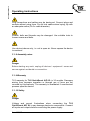
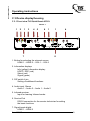
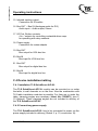
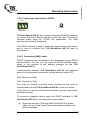
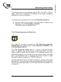
QuickScout A/D XL
Ident. No.: 863 9568
Installation and user manual
TLS Communication GmbH
Marie-Curie-Straße 20
D – 40721 Hilden
Tel.: +49 (0) 2103 50 06 - 0
Fax: +49 (0) 2103 50 06 - 90
e-mail: [email protected]
Operating instructions
Content
E
G
B
C 1 General Information ..................................................................... 3
C 2 Application area and intended use ............................................... 8
C 3 Device display/housing ................................................................ 9
C 4 Device installation/cabling .......................................................... 11
C 5 Initial operation ........................................................................... 19
C 6 Operation.................................................................................... 42
C 7 – 9 N.N. ...................................................................................... 44
C 10 Options ..................................................................................... 44
C 11 Care, maintenance, disposal, support...................................... 46
C 12 FAQ .......................................................................................... 47
C 13 Wiring diagram and other diagrams ......................................... 47
2
As of 06/13
Operating instructions
C 1 General Information
C 1.1 Identification
Manufacturer: ........................................... TLS Communication GmbH
Marie-Curie-Straße 20
D-40721 Hilden
Tel: +49 (0) 2103 5006 0
Fax: +49 (0) 2103 5006 90
Product:............................................................... QuickScout AD XL
Version: .......................................................................................... 1.0
Installation and user manual: ............................................ State 06/13
File edition:...................................................... Quickscout AD XL.doc
Ident. No.: ............................................................................. 8639568
These operating instructions are a part of this product. They
contain important notes on handling the device. Please remember
this also if you pass on the device to third parties. Keep these
operating instructions for further reference.
Imprint
These operating instructions are published by TLS
Communication GmbH. All rights, including translation, reserved.
Reproduction of any kind, e.g. photocopies, microfilms or
capturing through electronic data processing equipment requires
written approval by the publisher. Reprint, also in part, is
prohibited. These operating instructions reflect the technical status
at the time of going to press. Technological and design changes
are reserved.
As of 06/13
3
Operating instructions
C 1.2 Scope of delivery
Consisting of:
TLS QuickScout A/D XL
Ident. No.:
1 x QuickScout A/D XL
1 x Mains adaptor
1 x Manual
863 9586
870 6599
870 6681
C 1.3 Technical data
Power supply: ...............................................................................5 V DC
Input current: ..................................................................... max. 1200 mA
Operating voltage:.........................................................................5 V DC
Performance: ..................................................................................... 6 W
Switching outputs max.: .................................................... 30 V / 300 mA
Connections: ............................................................................................
Inputs: ................................................ 4 x ext. input (2+5 pin Phoenix m)
Outputs: ........................................... 5 x ext. output (2+5 pin Phoenix m)
....................................................................... 1 x IR (2x2 pin Phoenix m)
(Ident. No.: 8640100) ........................... 1 x RS232 (2 x 3 pin Phoenix m)
(Ident. No.: 8640105) ................................. 1 x RS232 (3 pin Phoenix m)
HDMI
Plug&Play DDC Mode .............................................................................
Inputs: ......................................................... 1 x 24+5 pin DVI-I f (Bus IN)
..................................................................... 2 x 19 pin HDMI f (IN1, IN2)
................................................... 3 x 3,5 mm Stereo jack (IN1, IN2, Bus)
............................................................ 2 x 2,5 mm jack (extern IN1, IN2)
Outputs: .................................................. 1 x 24+5 pin DVI-I f (Bus OUT)
.......................................................... 1 x 3,5 mm Stereo jack (Bus OUT)
.......................................................................... 1 x 2 pin clamp (Control)
Video bandwidth: .......................................................................2,5 Gbps
Resolution max.: ..................................................... 1080p / 1920 x 1200
Possible resolutions: ........ 480i/p, 720i/p, 1080i/p bis 12-Bit colour depth
Compatibility: .......................................................................... HDMI 1.3a
Signal types: ............................................................... TMDS Single Link
4
As of 06/13
Operating instructions
VGA + Audio
Input signals: ........................................................................ 0,7Vss RGB
..................................................................................................... 5 V H/V
.................................................................................. 5 V Sonstige (VGA)
................................................................................................4,5V Audio
Output signals: .................................................................... 0,7 Vss RGB
...................................................................................................... 5V H/V
............................................................................................. 5 V Sonstige
...............................................................................................4,5 V Audio
RGB bandwidth: ............................................................. 350 MHz (±3dB)
H/V Synchronisation: ..................................................... 250 KHz/520 Hz
Weight:............................................................................................. 355 g
Width: .......................................................................................... 100 mm
Depth: ......................................................................................... 110 mm
Height:........................................................................................... 42 mm
C 1.4 Environmental conditions
Operating temperature: ........................................... +5°C up to +40°C
Rel. humidity: ...................................................................... Max. 85%
Atmospheric pressure: ............................................ 600 bis 1000 hPA
C 1.5 In case of damage in transport
In case of transport damage, please observe the following:
Do not change the goods and the packaging in any way.
Let the deliverer sign for the damage.
Do not use the damaged device.
In case of delivery by a forwarding agent or parcel service,
please notify us of the damage telephonically or in writing within
5 calender days.
Do not return the device without prior consultation!
Please note that we only accept returned goods if agreed to
accept the return in advance.
Non-compliance with these regulations invalidates any claim for
compensation!
As of 06/13
5
Operating instructions
The following regulations and safety notes regarding installation
and maintenance must be observed:
C 1.6 Standards and regulations
VDE 0100
Regulations for erection of power installations for rated
voltages below 1000V.
VDE 0105
Operating power installations, general stipulations.
EN 60335-1 Safety of household and similar electrical appliances.
C 1.7 General safety notes
This operating instructions contains basic notes to be observed when
operating TLS QuickScout A/D XL. Follow the instructions closely to
avoid errors. It is therefore imperative to read these operating
instructions before working with TLS QuickScout A/D XL.
The safety notes contained in these instructions that result in hazards
to persons unless observed, are indicated by the
Safety symbol in acc. With DIN 4844-W8 and the word “Danger”.
Work on electrical components or component groups may only be
performed by a qualified electrician in acc. with electrical regulations
(e.g. EN 60204, DIN VDE 0100/0113/0160).
6
As of 06/13
Operating instructions
Plug connections and cables may be destroyed. Connect plugs and
sockets without using force. Do not kink cables when laying; lay with
an adequate radius (R>5 x cable diameter).
Screws, bolts and threads may be damaged. Use suitable tools to
loosen screws and bolts.
Use device indoors only, i.e. not in open air. Never expose the device
to moisture!
C 1.8 Assembly notes
Danger
Before starting any work, unplug all devices / equipment / areas and
secure against accidental re-connection.
C 1.9 Warranty
TLS warranty for TLS QuickScout A/D XL is 36 months. Damages
arising from improper operation or through use of force are not
covered by this warranty. The warranty is invalidated if unauthorised
persons open the device.
C 1.10 Safety
Danger
Voltage and current fluctuations when connecting the TLS
QuickScout A/D XL k may damage electronic components. Connect
all inputs and outputs before connecting the power supply.
As of 06/13
7
Operating instructions
Danger
Allow technical staff only to connect the device. (e.g. EN 60204, DIN
VDE 0100/0113/0160)
Danger
Electrical shocks from the power supply units may be fatal or lead to
grave injury to health. Never open the housing of the TLS
QuickScout A/D XL.
C 2 Application area and intended use
The TLS QuickScout AD XL is used to switch two analogue and two
digital sources on a display device. The integrated control capability
selects according to the signal source the respective input. This
guarantees a high quality image transmission in original quality. The
use of quality affecting image conversion or compressions is
excluded.
Furthermore TLS QuickScout A/D XL executes control tasks such
as switch on and off of the display device, the control of the screen,
the projector lift or other peripheric devices via RS232 or infrared.
Also the time controlled switching on and off of a projector is
possible.
The configuration of the multiple possibilites of TLS QuickScout A/D
XL is carried out with the Windows-Software configuration tool TLS
QuickScout A/D XL or via terminal program directly in the device.
In connection with further TLS QuickScout AD, TLS QuickScout A or
TLS QuickScout D devices the system can be expanded flexibly and
customised for any conference room.
The user gets a powerful system with maximum ease of use, which
convinces with highest image quality and operates maintenance-free.
8
As of 06/13
Operating instructions
C 3 Device display/housing
C 3.1 Front view TLS QuickScout A/D XL
Sketch 1
1
2
1
Info
HDCP
Select
Signal
HDMI 1
Select
3
1
HDMI 2
HDMI 1
2
3
DIP 1
4
5
6
1
1
4
Info
DDC
Select
Signal
4
Audio 1
Digital
Audio 2 IR
Service
HDMI 2
VGA 1
Select
QuickScout A/D XL
7
VGA 2
VGA 1
Audio 1
Analog
Audio 2
VGA 2
8
1. Button for selecting the relevant source:
HDMI 1 – HDMI 2 – VGA 1 – VGA 2
2. Information displays
Info (yellow) Information display
HDCP / DDC (red)
Select (red)
Signal (green)
3. DIP switch 4 pin
Setting of additional functions
4. Audio input, Stereo
Audio 1 – Audio 2 – Audio 1 – Audio 2
5. Infrared-receiver
Input for learning Infrared codes
6. Service-Port
RS232 connection for the service technician for setting
the basic functions
7. Signal inputs digital
HDMI 1 – HDMI 2
As of 06/13
9
Operating instructions
8. Signal inputs analogue
VGA 1 – VGA 2
C 3.2 Rear view TLS QuickScout A/D XL
Sketch 2
9
10
11
C
Control
C
Bus OUT
Bus OUT
GL
Analog
19
12
Sw LED
IN 1
Sw LED
IN 2
13 14 15
C
Control
Tx Rx
RS232
16
17
IR
IR
1
Bus OUT
Bus IN
Bus OUT
20
21
Bus IN
Digital
2
3
I/O
4
12 18
Sw LED
IN 1
Sw LED
IN 2
Bus IN
22
9. Control output (analogue)
Output for control signal
10. Bus-OUT (VGA)
Audio output, Stereo
11. GL-contact
Output for connecting the relay box GreenLine
12. Inputs for external buttons
IN1 – IN2 – IN1 – IN2
lit up
13. Control output (digital)
Output for control signal
14. RS232 output
Serial output for controlling the display device
10
As of 06/13
5V
Power
Operating instructions
15. Infrared sending output
Connection for IR emitter
16. Bus OUT – Bus IN (Analogue audio for DVI)
Audio input – Audio output, Stereo
17. I/O Port, Button contacts
4 in- / outputs for controlling contacts/buttons resp.
for operating with relay contacts
18. Power supply
Connection for mains adapter
19. Bus OUT
Bus output for VGA bus line
20. Bus IN
Bus input für VGA bus line
21. Bus OUT
Bus output for digital bus line
22. Bus IN
Bus input for digital bus line
C 4 Device installation/cabling
C 4.1 Installation TLS QuickScout A/D XL
The TLS QuickScout A/D XL module can be mounted on or under
the table, in wall channels or on the floor. Also the combination with
TLS table installation modules is possible. For fixing on or under the
table, clamping angles are necessary (Ident. No.: 8639571) (see C
10 Options). These clamping angles are not included in delivery of
the TLS QuickScout A/D XL.
C 4.2 Connectiong power supply
The TLS QuickScout A/D XL has to be connected to power via the
power supply included in delivery (Sketch 2, p. 10, connection 18).
As of 06/13
11
Operating instructions
Connect the module power supply to the power socket, only after
having connected the display device and the audio playback device
to the TLS QuickScout A/D XL. Only now switch on the devices /
systems / room.
C 4.3. Connecting display device and audio playback device
The TLS QuickScout A/D XL connects analogue and digital sources
via an analogue (VGA) and a digital (DVI) cable run to the display
device.
Digital:
If the connection on the display device and on all sources connected
to the system are HDMI, the audio signal will be transmitted via the
DVI/HDMI bus. No additional audio cable is needed.
If additional DVI sources resp. a DVI display device is used,
additional audio cable is needed.
For an optimal image and audio quality we recommend you to use
the TLS DVI cable (Ident. No.: 8633000) as well as the TLS audio
cable (Ident. No.: 8365599) for TLS QuickScout A/D XL.
If DVI devices are used, connect the TLS QuickScout A/D XL
with a TLS DVI connection cable via the appropriate DVI output
BUS OUT (Sketch 2, p. 10, connection 21) with your display
device (e. g. LCD or projector).
with a TLS audio connection cable über via the appropriate
audio output BUS OUT (Sketch 2, p. 10, connection 16) with
your audio playback device (e. g. amplifier).
If the connection on the display device and on all sources are HDMI,
you only need to connect the QuickScout A/D XL with your display
device via the DVI-HDMI connection cable.
12
As of 06/13
Operating instructions
You can find information regarding the possible cable lengths with
TLS digital cables on the cable matrix:
http://www.tls-gmbh.com/HDMI.804.0.html
Analogue:
The analogue audio signal and the analogue video signal are
transmitted by only one VGA cable at TLS QuickScout A/D
XL. This cable must be a TLS WUXGA cable. Only this cable
has all required signal and data lines.
You can find information regarding the possible cable lengths with
TLS WUXGA cables on the cable matrix:
http://www.tls-gmbh.com/VGA.820.0.html
C 4.4 Connecting switching in- and outputs, I/O Ports
Danger
Safety instructions at connections
Electrostatically endangered components ESD!
Electrostatic discharges can cause damages in integrated circuit
devices!
Avoid direct contact of single connection contacts of TLS
QuickScout A/D XL! If this is not possible, please at least ensure
before touching, that you are not electrostatically charged. By
touching grounded metal parts, electrostatic energy can be diverted.
It should furthermore be ensured, that there is no recharge.
1
2
3
4
I/O
As of 06/13
13
Operating instructions
The TLS QuickScout A/D XL has 4 I/O in-/outputs which can be
flexibly switched. The inputs and the ground potential are located in a
five pin connector. A connection of an inputs with the ground potential
releases an input impulse.
The outputs are Open Drain in design, in order to allow different
potentials of up to 30V.
Explanation:
An open collector is a common type of output found on many
integrated circuits (IC). Instead of outputting a signal of a specific
voltage or current, the output signal is applied to the base of an
internal NPN transistor whose collector is externalized (open) on a
pin of the IC. The emitter of the transistor is connected internally to
the ground pin. If the output device is a MOSFET the output is called
open drain and it functions in a similar way.
If the outputs are switched on by the configuration, there is ground
potential at the respective output.
You must ensure that the maximum current of 300mA is not
exceeded.
Explanation:
The ground potential is defined by Potential 0 Volt and is the
reference potential for all impulse and operating voltages. The
electrical potential is a voltage specification which references a fixed
reference point.
C 4.5 Connecting infrared outputs
1
TLS QuickScout A/D XL has an infrared output. Up to three infrared
emitters can be connected in series to each output.
14
As of 06/13
Operating instructions
C 4.5.1 Connecting infrared emitter
Via infrared communication infrared commands are transmitted from
TLS QuickScout A/D XL to play-back devices. For this you need an
infrared emitter, which is not included in delivery package of TLS
QuickScout A/D XL.
Connect the red/blue marked cable (at TLS types) with screen
in a 2pin Phoenix connector included in delivery.
Then connect the assembled connecting cable of the IR emitter
to the terminal block at the IR port (contact terminals IR-OUT
and GND) at the back side of TLS QuickScout A/D XL.
Please ensure that the red respectively blue marked cable (IR
emitter) is connected with the terminal IR and the screen (earth
lead) is connected with the terminal GND .
Then remove the protective film from the IR emitter and
connect the emitter at the relevant end devices directly to the
infrared receiver. This is usually marked with IR.
C 4.5.2 Single and/or dual IR emitter
Up to three IR emitter in series can be connected per output. For this
a single and/or dual IR emitter is available from TLS (Ident. No.: 864
0027 (single) / 864 0028 (dual)).
C 4.5.3 Infrared extension
If you need an extension for the infrared cable, a 2-pole cable with
plug and socket is available from TLS.
As of 06/13
15
Operating instructions
C 4.6 Connecting serial interface RS232
Tx Rx
Service
RS232.1
TLS QuickScout A/D XL has 2 serial bi-directional RS232 interfaces
on its rear side and a service interface on its front side. The service
interface works using the 115200 8N1 parameters. The other
interface can be freely configured.
This RS232 interface is used to control the display device, the service
port is used to configure the TLS QuickScout A/D XL and for
maintenance.
C 4.6.1 Connecting RS232 cable
RS232 commands are transmitted to the end-devices using RS232
communication. For this, you will need an RS232 interface cable,
which is not included in the delivery package for the TLS
QuickScout A/D XL.
Communication between TLS QuickScout A/D XL and playback
device is uni-directional, meaning in a single direction using TxD.
RxD: Receive (x) Data
TxD: Transmit (x) Data
Two lines for ground and data (send) respectively are used to
transfer data from the TLS QuickScout A/D XL to the end-device.
Three lines are used for bi-directional transfers: ground, data (send)
and data (receive).
To connect a playback device using the RS232 interface to TLS
QuickScout A/D XL for uni-directional communication,
Screw the two lines (TxD and GND) of the RS232 interface
cable into one of the 3-pole Phoenix terminals included in the
delivery package.
16
As of 06/13
Operating instructions
Connect the thus ready-to-use line with the terminal block to
the RS232 port (contact terminals TxD and GND) on the rear
side of the TLS QuickScout A/D XL.
Now connect the other end of the RS232 interface cable to the
RS232 input of the playback device.
When doing this, the TxD data line should be connected to the
Rx port (receive port) of the playback device.
To connect a computer to the bi-directional service port, you need a
special RS232-3,5mm plug cable. You can purchase this cable from
TLS as a set with an adapter from USB to RS232. (QuickScout
Configuration tool USB/RS232 Ident.Nr. 8630054).
By using this you can connect a computer with an USB interface with
the RS232 service port of the TLS QuickScout A/D XL, to configure
the TLS QuickScout A/D XL.
C 4.7 Connecting external buttons
Sw LED
IN 1
The inputs IN1 and IN2 on the backside oft he device are used to
connect external buttons for selecting the input sources at the TLS
QuickScout A/D XL. These buttons can be lit up.
You can purchase from TLS external table modules with 1 or 2
analogue inputs (Ident. No.: 863 9576 or 863 9577) resp. table
modules for connecting 1 or 2 digital HDMI inputs (Ident. No.
8639581 or 8639582). There are also available hybrid analoguedigital table modules for 2 resp. 4 user (Ident. No. 8639588 or
8639589).
These buttons and external table modules are not included in the
delivery pack of TLS QuickScout A/D XL.
As of 06/13
17
Operating instructions
The external buttons are equipped with a LED. The LED is used to
diplay, which user is selected. The display of the signal recognition
continues to occur at the device.
To connect the external buttons to the TLS QuickScout A/D XL,
plug the cable of the buttons in the inputs IN 1 to IN 4 on the
backside of the TLS QuickScout A/D XL.
The buttons are now ready for use.
C 4.8 Connecting relay box GreenLine
G
GL
The output GL is used to connect the TLS GreenLine relay box
doublepartet with internal power supply (Ident.No. 8639983) to the
TLS QuickScout A/D XL.
The TLS GreenLine Relax box is a remote controlled multiple
switch. In addition, the device can also, when used with a TLS room
control system, switch all the poles of a connected device (e.g.
data/video projector) on or off after a pre-set period of time. The relay
box is pre assembled with a connector plug at the 115/230 V cable
and with a rubber connector for 115/230 V devices.
Connect with the Phoenix connector included in delivery the ground
potential 0 V of the relay box to the ground potential of the output GL.
Connect the switching contact 1 of the relay box with the contact G of
the input GL.
18
As of 06/13
Operating instructions
C 4.9 Connecting Control output
C
Control
If you would like to control TLS QuickScout A/D XL externally, you
can connect an external control via the 2 pin Phoenix connector
Control. The TLS QuickScout A/D XL system recognises the
pressing at select buttons for analogue or digital video signals and
reports this on both outputs Control in the analogue or digital field.
The external control can evaluate this information and selects at the
display device the input required for the system.
As the Control connection is bi-directional, the external control can
also execute the „complement reset function“(page 33). For that the
external control must close the contact for more than 200 ms. If the
contact gets closed for more than 5 s, the TLS QuickScout A/D XL
gets switched off.
In addition the external control, e. g. die TLS GlobalControl, can
execute further control tasks and even send SMS and Emails resp.
respond to incoming messages. Also the control via a browser
interface or a TLS Touch panel is easily possible.
For this connect the ground potential 0V with the ground potential of
the external control and each of the two signal contacts C with an
input of the external control.
C 5 Initial operation
After having connected TLS QuickScout A/D XL to the power
supply, you must press any Select button to switch on the device.
Now the corresponding Select LED lights up red. The device is now
ready for operation.
When using a HDMI notebook: Connect your notebook with a
HDMI/HDMI cable to the TLS QuickScout A/D XL at the female
connector HDMI 1 or HDMI 2 (sketch 1, page 9).
As of 06/13
19
Operating instructions
When using a DVI notebook: Connect your notebook with a
DVI/HDMI cable to the TLS QuickScout A/D XL at the female
connector HDMI 1 or HDMI 2 (sketch 1). Connect the audio output
of the DVI notebook with a stereo audio cable to the TLS
QuickScout A/D XL at the corresponding female connector
Audio 1 or Audio 2 (sketch 1, page 9).
When using a VGA notebook: Connect your notebook with a
VGA cable to the TLS QuickScoutAD XL at the female connector
VGA 1 or VGA 2 (sketch 1, page 9). Connect the audio output of
the VGA notebook with a stereo audio cable to the TLS
QuickScout A/D XL at the corresponding female connector
Audio 1 or Audio 2 (sketch 1, page 9).
C 5.1 DIP switch
The DIP switches on the front side of the device do not have any
function for the operation in practice – they are used for internal test
functions during production.
This reference does not apply to older devices of the TLS
QuickScout system.
C 5.2 Software
The configuration of the TLS QuickScout A/D XL can be carried out
with the PC software TLS QuickScout A/D autoswitch
configuration tool.
This requires a Windows PC with Windows XP SP3 or Windows7.
Otherwise a terminal program can be applied for configuration, e. g.
Hterm. Hence the configuration of TLS QuickScout A/D XL is also
possible with other operation systems.
In both cases a serial connection must be established between the
PC and TLS QuickScout A/D XL.
20
As of 06/13
Operating instructions
C 5.2.1 PC software
The PC software must be installed into a directory on your PC from
the CD included in delivery.
Afterwards open the software. Please note, that you generally need
an adaptor USB-RS232 and a cable for the communication with the
TLS QuickScout A/D XL (see C 4.6)
C 5.2.1.1 The home screen
Via the home screen you reach the main program functions of a
Windows program.
You can create and open a new project, or save an existing one.
As of 06/13
21
Operating instructions
C 5.2.1.2 System settings
With the screen system settings you will be able to configure basic
system settings.
C 5.2.1.2.1 Projector timings
In the first menu item Projector timings you define the specified time
of the projector or the display device.
22
As of 06/13
Operating instructions
Start up time and safety time of the projector are usually not included
in the projector manual. As an indicative value, for the start up time a
value between 10 and 30 sec. is recommended, and for the safety
time twice the cool down time.
The following projector times are to set:
Projector start up time:
This is the time the projector requires to reach a pre-defined state
after its power supply has been switched on. This is generally about
10 sec.
Projector warm up time:
Warm up time is the time the projector lamp requires to warm up. The
projector cannot accept and execute commands during this period. It
is important in this respect to allow the projector sufficient time to be
ready to react to control commands.
As of 06/13
23
Operating instructions
System stop time:
The system stop time defines, how long no signal must be active,
until the projector gets switched off automatically. Herewith you can
prevent, that the projector will be switched off unnecessarily, if the
connected notebook during operation gets on stand-by and sends no
signal. If there is no signal at the system, the stop time begins.
Thereupon the yellow Info-LED lights up. If there is a signal again,
the yellow LED goes off and the timer will be reset.
Projector cool down time:
Cool down time is the time the projector lamp requires to cool down.
This period should be long enough to allow the projector to
completely cool off the lamp before switching off the mains supply.
The lamp may otherwise be damaged.
Projector safety time:
The safety time is the period required in case the projector has been
switched off without first cooling down the lamp. The lamp may be
damaged if the projector is switched back on immediately.
C 5.2.1.2.2 RS 232 Protocol
In this menu item the communication parameters of the display
device to be controlled can be set up. Please refer to the device
manual for the relevant data.
24
As of 06/13
Operating instructions
C 5.2.1.2.3 Device settings
The menu item Device settings is used amongst others to configure
the many possibilities of the TLS QuickScout A/D XL to control the
EDID and DDC data of the video inputs.
Furthermore also operation modes of the select buttons, the audio
switching and other hardware configurations can be made.
As of 06/13
25
Operating instructions
EDID mode
This column is used configure the EDID and DDC operation modes.
EDID locked mode
In this operation mode the EDID data set of the display device is
stored in the memory of the TLS QuickScout A/D XL and is
displayed constantly to all signal sources. In this way the signal
output of every connected signal sources remains active, although
another input channel has been selected. If to another source will be
switched, this source is able to send instantly.
Furthermore this operation mode enables to respond also to inadequate
connection cables to the display device, which might be technically
not able to guarantee an EDID communication the display device. At
the begin of the installation the TLS QuickScout A/D XL has to be
connected once only with a TLS cable to the display device.
Hereupon the TLS QuickScout A/D XL can save the EDID data set
and store it permanently in the device memory. Now the signal
sources access this data set and send hereupon a signal to the
display device.
26
As of 06/13
Operating instructions
To avoid this kind of problems, it is therefore recommended anyway
to use high-quality TLS cables, not only to enable the EDID
communication, but also to guarantee highest transmission quality.
EDID direct connection
In this operation mode a permanent EDID connection between signal
source and display device is provided. This operation mode is
required e. g. to ensure permanent communication in the HDMI
operation with HDCP. Thus a permanent exchange of the HDCP
keys is possible. Also recent VGA signal sources require in part this
option, as they have to communicate permanently with the display
device, too and then also have to resend instantly while switching.
Enable HPD reset HDMI 1 – 2 (HPD = Hot Plug Detect)
In this operation mode by selecting HDM1 respectively HDMI2 of the
signal source a control signal corresponding to Hot-Plugging is
transmitted to the display device. Hereupon the communication from
the signal source with the display device starts. The control signal
transmitted initiates e. g. the switching on of the display device
Anzeigegerätes from standby mode.
Enable always read DDC
In this operation mode in the communication between signal source
and display device always the complete data set is read and
processed. However mostly a shortened form of this data set is
already sufficient for the communication, so that this operation mode
can be deactivated. Thus the switching wird der switching procedure
even quicker.
Toggle VGA 1 / HDMI 1 (VGA2 / HDMI2)
This operation mode allows for a „2 button operation mode“ of the
TLS QuickScout A/D XL. The inputs VGA1/HDMI1 and
VGA2/HDMI2 are summarised each to a group and thus seem to be
connected. Now each on IN1 of the VGA side and on IN1 of the
HDMI side an external button has to be connected.
As of 06/13
27
Operating instructions
A press of the button 1 VGA now switches to the group
VGA1/HDMI1, A press of the button 1 HDMI switches to the group
VGA2/HDMI2.
In connection with the operation mode:
Signal detection enabled
Offers a powerful version of the use of TLS QuickScout A/D XL. The
activivated signal detection causes, when toggling between the
groups VGA1/HDMI 1 and VGA 2/HDMI2, always the switch to the
active input. If both inputs of a group are active, the switch is always
effected to the input lastly active. By pressing again this button, the
other channel of this side is selected.
In that way an operation in 2 groups is possible, irrespective of
whether analogue or digital signals are used. Always the active signal
is switched to the display device and is displayed in highest quality.
Enable external Input
This function activates the 4 inputs for external buttons IN1-IN2 (see
C 4.7).
Use the audio channels separately
In this operation mode both the audio channels (VGA + Audio) (DVI +
Audio) are transmitted separately through the system and distributed
at the final point on two separate outputs (VGA Bus OUT / HDMI Bus
OUT).
Combine Audio Channels
In this operation mode all audio inputs get connected and distributed
at the end of the system at the point Bus OUT of the VGA side.
Thereby you need only one audio line to the amplifier/display device.
If you plan a TLS QuickScout A/D system with more devices, you
also need only one audio connecting cable. By pressing a select
button now the relevant audio is distributed.
28
As of 06/13
Operating instructions
Enable only one audio
In this operation mode only the audio inputs VGA-Audio 1 and VGAAudio 2 are active and are distributed at Bus OUT of the VGA side.
When pressing the button 1 (HDMI 1 or VGA 1), the audio from VGAAudio 1 is directed to the output. When pressing the button 2 (HDMI
2 oder VGA 2) the audio from input VGA-Audio 2 is directed to the
output.
This operation mode enables in combination with the operation
modes Toggle VGA1/HDM1 and signal detection enabled an
intelligent solution with a TLS QuickScout A/D XL and each two
VGA/HDMI/Audio connection plates with one button. Therewith an
operation in 2 groups is possible, irrespective of whether analogue or
digital signals are used. Always the active signal is switched to the
display device and is displayed in highest quality.
Therewith an user can connect himself with any signal to his
connection plate, connects his audio signal and selects with his
button the connection to the display device.
Enable debugging mode
This operation mode is selected by the service technician, in order to
analyse the internal program sequences in the TLS QuickScout A/D
XL by means of the connected terminal program.
Enable Control IO
In this operation mode both Control Ports are activated. This enables
an external control to detect, which signal sources (digital or
analogue) are activated by a press of a button respectively which
special key functions are selected. An external control can evaluate
this information and thereby control the display device accordingly.
The Control Port displays three different information.
Control Port closed for 250 ms:
Control Port closed für 2 s:
Control Port closed für 5 s:
As of 06/13
Keystroke
Presentation Check
Switch off the system
29
Operating instructions
Enable complement reset
This operation mode must be activated in TLS QuickScout A/D XL
in order to process the switching between the signal sources
properly.
Warning: At a QuickScout AD system with several devices only
one device may have this function activated.
Enable power save modus
In this operation mode the TLS QuickScout A/D XL is set into an
energy saving mode after 10 s without any function. As soon as there
is a signal again, or a button is pressed, the device will leave the
energy saving mode.
Enable digital signal amplifying circuit
In this operation mode the integrated amplifier for digital video signals
gets activated. You need this operation mode, if you use very long
HDMI or DVI cables to the signal inputs. For information regarding
the admissible cable lengths with TLS digital cables, please refer to
the following cable matrix:
http://www.tls-gmbh.com/HDMI.804.0.html
Enable device is on last place
This operation mode must be selected at last QuickScout device of a
QuickScout system. The last device is the one, which is nearest to
the diplay device.
A single TLS QuickScout A/D XL must be always last place.
Thereby the last device is able to decouple the control signals from
the video lines and to process them accordingly.
30
As of 06/13
Operating instructions
C 5.2.1.2.4 XL Settings – System ON / OFF
In these input fields you define the turn on and off behaviour of TLS
QuickScout A/D XL.
Use the ON /OFF button to switch ON / OFF the system
In this operation mode the inputs 1 + 2 of the I/O Port (see C 4.4)
become inputs for buttons. Input 1 is used to switch the system on,
Input 2 to switch it off.
Use the ON button as a toggle button to switch On / OFF the
system
In this operation mode the input 1 of the I/O Ports (see C 4.4) is used
to switch the system on and off. The input is operated in toggle mode.
Use ON button with keyswitch to switch ON / OFF the system
In this operation mode a key switch can be integrated at input 1 of the
I/O Port (see C 4.4). With this you switch the system on and off.
Once the key switch is opened, the system gets switched off,
otherwise it gets switched on.
As of 06/13
31
Operating instructions
You can get the key switch from TLS under Ident. No 8639358 and
under Ident. No. 8639682.
Don´t use external inputs to switch ON / OFF the system
This operation mode turns off the use of the input function of the I/O
ports 1 + 2 and enables the operation as an output.
Use the signal identification to switch ON / OFF the system
This operation mode activates the signal detection at all signal inputs.
With it a key stroke will only cause a switching on of the system,
when there is effectively a video signal. An accidentally switch on of
the system, e. g. by cleaning work, is thus prevented.
Use the system select button to switch ON / OFF the system
This operation mode can be activated to allow for an easy switch on
of the system at one of the 4 Select buttons. It is recommended to
combine this function with the activated signal detection of the TLS
QuickScout A/D XL.
With it a key stroke will only cause a switch on of the system, when
there is effectively a video signal. An accidentally switch on of the
system, e. g. by cleaning work, is thus prevented. (see C 5.2.1.2.3)
System OFF mode enabled
This operation mode enables the switch off of the TLS QuickScout
A/D XL by means of the select buttons. A key stroke of 5 s causes
the switch off of the system. Hereupon the projector will be shut down
according to the settings in Projector timings and can be taken off of
the 230V mains by means of the Relay box Greenline at the output
GL. Afterwards the Power save mode will be activated.
32
As of 06/13
Operating instructions
XL Settings – Output settings
ON:
Output 1
OFF:
Output 2
DOWN:
Output 3
UP:
Output 4
At this point the characteristics of the 4 outputs are defined. The
timings are entered in seconds in the operation mode „activate for
time x“. In addition every output can assume the operation modes
„activate“ or „release“.
The outputs 1 and 3 as well as 2 and 4 in addition are coupled. In
that way in practice pressing the button 1 will switch on the system
and afterwards will lower the screen with output 3. The same way
pressing the button 2 will switch off the system and afterwards run up
the screen.
Warning: If the inputs 1 and 2 are used for switching on and off,
or a key switch is used, these inputs will have no further
function.
Otherwise the point “Don´t use external inputs to switch ON/OFF
the system“ in the settings above must be selected.
C 5.2.1.3 Key Commands
In this menu item you can learn the IR-Codes, repectively enter the
RS232 codes, which are used to control the display device.
Key 1 and key 2 are used to control the switching on/off function of
the display device, key 3 and Key 4 activate, depending on the
system status, or the analogue input or the digital input of the display
device.
As of 06/13
33
Operating instructions
The RS232 control codes can be entered as decimal, hexadecimal or
ASCII value in the respective table. To enter RS232 control codes,
the field RS232 must be activated.
Please note, that when entering a hexadecimal value, a % character
hast to be entered before each number value. The inputs have to be
done without spaces!
Note: Please ask the device manufacturer for the RS232 control
codes of the display device.
Key 1 and key 2 can incorporate each multiple control sequences as
display devices partly are switched on/off in a multilevel way. The
pause between the control sequences is used to process the
respective control sequence. Once learned IR codes can be copied,
pasted and deleted with the functions „copy“, „paste“, „clear“ and
„cut“. The function „cut“ trims a learned IR code to exactly one code
sequence.
As most IR remote controls transmit continuously, in that way an IR
code can be defined more precise and the target device can identify
the code sequence exactly.
34
As of 06/13
Operating instructions
Each page has the Learn function for teaching infrared codes via
your remote control. For this please click on the Learn button and
another window appears:
Press the start button. A timer starts running. You now have 10
seconds to teach the required IR code.
After successful teaching, the IR window contains the IR code in
hex format.
The codes are fully compatible with the Hex Pronto format.
After successful teaching, the tool does report this and the IR code is
transferred to the associated window.
It sometimes may happen, that an IR code has been read incorrectly.
Possible sources of interference are e. g. high ambient brightness,
neon lamps or halogen spot lights.
Thus the test function serves as immediate test of the learned IR
code. Connect an IR emitter to the IR output and attach the emitter
directly on the receiver of the device to be controlled. Press the Test
button and check the proper function of the device to be controlled.
As of 06/13
35
Operating instructions
In addition the Test function serves also to check the RS232 control
sequences entered by you. Establish a RS232 connection to the
device to be controlled and press the Test button. In that way you can
verify directly the RS232 sequences after having entered them.
Use the Test function! You will receive faultless control codes!
The functions Key 3 and Key 4 contain even six input fields to be able
to process enough control sequences for the selection of the
appropriate analogue or digital input of the display device.
Especially in the operation mode Infrared partly several different IR
codes are required, to switch the display device reliably.
36
As of 06/13
Operating instructions
C 5.2.1.4 Transfer
With the menu item Transfer you execute the communication with
the TLS QuickScout A/D XL.
With the function Save you send your configuration to the TLS
QuickScout A/D XL. The configuration will now be stored
permanently in the device.
With the function Read an existing configuration will be uploaded
from TLS QuickScout A/D XL and be displayed on your PC in the
configuration software. Now you can change this configuration for
example to adjust a new display device.
Subsequently you store the modified configuration with the Save
function again in the TLS QuickScout A/D XL.
As of 06/13
37
Operating instructions
C 5.3 Configuration with a terminal program
In case you don’t have a computer with a Windows operating system
available, you still can configure the TLS QuickScout A/D XL.
Use the operating system’s terminal program and first establish a
RS232 connection to the Service-Port. The connection parameters
are: 115200, N, 8, 1
Afterwards plug the power supply of the TLS QuickScout A/D XL in
the power socket. Now following request appears in your terminal
program:
Press a key on your computer and you’ll get an overview of five
options.
C 5.3.1 Help
With this you will automatically be taken to another menu, where you
can
38
As of 06/13
Operating instructions
reset TLS QuickScout A/D XL to factory settings
activate the debug mode
read the serial number
get further assistance
leave the submenu
C 5.3.2 Functions
In this submenu you can configure the TLS QuickScout A/D XL. You
will find the options available here, in the category device settings of
the configuration software (see C 5.2.1.2.3 Device Settings).
As of 06/13
39
Operating instructions
C 5.3.3 Monitoring
Also in this menu item you get access to the configuration of TLS
QuickScout A/D XL. You will find the options available here
explained in the category device settings of the configuration
software (see C 5.2.1.2.3 Device Settings).
40
As of 06/13
Operating instructions
C 5.3.4 Audio
In this menu item you configure the audio options of TLS
QuickScout A/D XL. You will find the options available here
explained in the category device settings of the configuration
software (see C 5.2.1.2.3 Device Settings)
Enable only one audio
In this operation mode only the audio inputs VGA-Audio 1 and VGAAudio 2 are active and distributed at the point Bus OUT of the VGA
side. When pressing key 1 (HDMI 1 or VGA 1), the audio will be
conducted from input VGA-Audio 1 to the output. When pressing key
2 (HDMI 2 or VGA 2) the audio will be conducted from input VGAAudio 2 to the output.
Enable Master Audio
In this operation mode all audio inputs get connected and distributed
at the end of the system at the point Bus OUT of the VGA side.
Thereby you need only one audio line to the amplifier/display device.
By pressing a select button now the relevant audio is distributed. You
select this operation mode at a device placed “in the middle” of a TLS
QuickScout AD XL system.
As of 06/13
41
Operating instructions
Enable Master Audio AD
This operation mode is selected to interconnect all audio inputs at the
last device of a QuickScout AD XL system and to distribute point
Bus OUT of the VGA side. Thereby you need only one audio line to
the amplifier/display device. By pressing a select button now the
relevant audio is distributed.
C 6 Operation
C 6.1 Switching on the system
The switching on of the system is carried out – depending on the
configuration done – by pressing any Select button, an external
button or a key switch at TLS QuickScout A/D XL. Hereupon the
display device gets switched on and the adequate signal input gets
selected. Please note that the display device does need some time
for the system start. During the starting procedure the yellow InfoLED flashes.
It is recommended to combine this function with the activated signal
detection of the TLS QuickScout A/D XL. With it a key stroke will
only cause a switch on of the system, when there is effectively a
video signal. An accidentally switch on of the system, e. g. by
cleaning work, is thus prevented.
C 6.2 Signal detection / Selecting the connected notebooks
The TLS QuickScout A/D XL does recognise, whether there is a
VGA or HDMI signal at the respective input. This is signalised by the
green lighting of the signal-LED next to the respective buttons HDMI
1-2 and VGA 1-2. If the signal-LED flashes, there is a weak VGAsignal.
By pressing a select button the relevant source is selected and the
respective presentation is displayed on the common display device
(e. g. plasma, LCD screen or DV projector).
This is signalised by the red lighting of the corresponding Select
LED.
42
As of 06/13
Operating instructions
Warning: It may take some seconds for the display device to
recognize the signal directly after it has been selected.
C 6.3 Presentation Check Function
The presentation check function (video mute) allows every user a
discreet editing of his presentation also during ongoing operation by
the press of a button
If the connected notebook is selected, but temporarily no switch
through of the signals during ongoing operation is desired, you have
the possibility,
to interrupt the signal switching by pressing longer (approx. 2
sec.) the respective button
This will be indicated by the going out of the red Select LED. The
green lighting of the signal LED indicates that the video signal is still
there.
Now the screen content of the notebook can be seen locally, but will
not be displayed on the shared LCD/Plasma respectively DVprojector. By pressing again the button, the content is displayed
again.
C 6.4 Switching off the system
Switching off the TLS QuickScout A/D XL can be done in multiple
ways. Depending on the system configuration chosen by you, the
switching off occurs e. g. by pressing for 5 sec. a select button of the
TLS QuickScout A/D XL.
You can also connect a key switch and switch off the system by using
the key switch.
Also external buttons at Output 1 and 2 can be used to switch off the
system.
As of 06/13
43
Operating instructions
The signal detection in combination with a corresponding Stopp time
can also be used for switching off. Once the Stopp time has expired,
the yellow Info-LED flashes and the shutdown gets started. This
process can not be interrupted.
In all operation modes the display device is switched off by means of
infrared sequence or RS232 command. The relevant switch off and
safety times are being considered, of course. During the shut down
the Info LED flashes.
C 7 – 9 N.N.
C 10 Options
C 10.1 Expansion of TLS QuickScout Digital AD XL by further
participants
For the use of TLS QuickScout A/D XL with more than 4
participants, you can expand it to a complete system by using further
TLS QuickScout AD, TLS QuickScout A and TLS QuickScout D.
You can combine several analogue connections and several digital
connections in one system. If you are planning the installation of a
larger QuickScout system, possibly with partitions, you should
contact the technical support ([email protected]), to
check further technical details.
To interconnect the relative TLS QuickScout modules,
plug a TLS DVI connection cable (male/male) into the DVI
input provided BUS IN (Sketch 2) of the first module.
Now connect the other side of the DVI connection cable with
the DVI output BUS OUT (Sketch 2) of the second module.
Now connect all other modules in the same order, in which
each output of a module has to be connected to the input of the
next module.
44
As of 06/13
Operating instructions
Plug a TLS VGA connection cable (male/male) into the VGA
input provided VGA IN (Sketch 2) of the first module.
Now connect the other side of the VGA connection cable with
the VGA output VGA OUT (Sketch 2) of the second module.
Now connect all other modules in the same order, in which
each output of a module has to be connected to the input of the
next module.
C 10.2 Audio-Anschluss
Plug a TLS Audio connection cable (male/male) into the Audio
input provided (BUS IN) (Sketch 2) to the right of the dip switch
of the first module.
Now connect the other side of the Audio connection cable with
the Audio output BUS OUT (Sketch 2) to the left of the dip
switch of the second module.
Now connect all other modules in the same order, in which
each output of a module has to be connected to the input of the
next module.
Warning! Connect the module’s power supplies only to the power
socket, when having interconnected the modules first! Switch on the
devices / system / room only after that.
Now proceed as described under C 5 Initial operation.
As of 06/13
45
Operating instructions
C 11 Care, maintenance, disposal, support
C 11.1 Cleaning
Use a dry, soft cloth to clean TLS products; never use chemicals.
C 11.2 Disposal
If you want to discard your TLS device, dispose of the product in acc.
with current regulations. Contact your municipal collection point.
Manufacturer:
TLS Communication GmbH
Marie-Curie-Straße 20
40721 Hilden
WEEE Nr. 69124746
C 11.3 Support
For questions arising when operating the device or when in use,
please contact your local TLS dealer or TLS directly:
TLS Communication GmbH
Marie-Curie-Straße 20
D-40721 Hilden
Tel.: +49 (0) 2103 5006-0
Fax: +49 (0) 2103 5006-90
E-Mail: [email protected]
www.tls-gmbh.com
46
As of 06/13
Operating instructions
C 12 FAQ
Before contacting the customer service you may try to solve the
problem yourself by referring to the information provided in this
section.
The Select LED does not go off
The function Last Place is not activated.
I don’t get any any image with the BluRay Player.
The function EDID direct connection is not activated.
I don’t get any image on the display device
Have the original cables been installed?
Does the switching over of the input source work properly?
C 13 Wiring diagram and other diagrams
Illustration of an application example:
TLS QuickScout A/D XL with an upstream table installation module
TAM 201 and Desptop Module, control of a projector and screen.
As of 06/13
47
desktop modul
Cat 6
TAM 201
48
LAN 2
LAN 1
Audio
HDMI
VGA
TAM201
Cat 6
HDMI 1
Info
HDCP
Select
Signal
Select
HDMI 1
HDMI 2
DIP 1
Digital
Audio 1
Bus OUT
IR
Bus OUT
HDMI 2
Audio 2
Control
VGA 1
Bus IN
IN 1
QuickScout A/D XL
Service
Analog
GL
IN 2
Info
DDC
Select
Signal
Select
RS232
VGA 1
VGA 2
Control
Analog
I/O
Bus IN
IN 1
IN 2
5V
Power
Audio 2
VGA 2
device backside
Digital
Bus IN
Audio 1
Bus OUT
Bus OUT
IR
legend:
Screen
cable analog
cable DVI / HDMI
cable audio
cable 230V
cable control (signal recognition, ext. buttons)
cable RS232
cable IR
optional
speaker
projector
8639980
2 relay box
Operating instructions
As of 06/13
As of 06/13
DVI.Bus OUT
Audio.OUT
VGA.OUT
DVI.Bus IN
Audio.IN
VGA.IN
DVI.Bus OUT
Audio.OUT
VGA.OUT
DVI.Bus IN
Audio.IN
VGA.IN
49
HDMI.IN 2
Ext.IN2
Audio.IN 2
VGA.IN 2
Ext.IN2
Audio.IN 2
HDMI.IN 1
Ext.IN1
Audio.IN 1
VGA.IN 1
Ext.IN1
Audio.IN 1
DVI.Bus OUT
Audio.OUT
VGA.OUT
Audio.OUT
DVI.Bus IN
Audio.IN
VGA.IN
RS232.OUT
IR. OUT
I/O 1
I/O 2
I/O 3
I/O 4
GL
8639586
QuickScout A/D XL *
HDMI.IN 2
Ext.IN2
Audio.IN 2
VGA.IN 2
Ext.IN2
Audio.IN 2
HDMI.IN 1
Ext.IN1
Audio.IN 1
VGA.IN 1
Ext.IN1
Audio.IN 1
8639584
QuickScout A/D
HDMI.IN 2
Ext.IN2
Audio.IN 2
VGA.IN 2
Ext.IN2
Audio.IN 2
HDMI.IN 1
Ext.IN1
Audio.IN 1
VGA.IN 1
Ext.IN1
Audio.IN 1
8639584
QuickScout A/D
Legende:
Kabel VGA
Kabel DVI/HDMI
Kabel Audio
Kabel LAN
Kabel 230 V
Kabel Steuerleitung
Kabel RS232
Kabel IR
Lautsprecher
Audio OUT
RS232
VGA IN
Audio IN
HDMI IN
Projektor
Operating instructions
Illustration of an application example:
TLS QuickScout A/D XL system with 2 TLS QuickScout AD, control
of a projector.
Operating instructions
50
As of 06/13
Operating instructions
As of 06/13
51
Operating instructions
TLS Produktprogramm
Mobile Beschallungsanlagen
Computer-Trainings-Systeme
Sprachtrainingssysteme
Übertragungstechnik
Spezialkabel
TLS Product range
Portable Sound Systems
Computer Training Systems
Language Training Systems
Transmission Technology
Special Cables
Visit our Website:
www.tls-gmbh.com
This product complies with the European directives and standards, provided that it is
installed, maintained and used as described in the installation provisions and the
operating instructions. Technical data may be changed without prior notice.
52
As of 06/13