1
AutoSD Steel Detailing
AutoSD STEEL DETAILING
Reference Manual
Version 2015
i
AutoSD Steel Detailing
Copyright 1990 – 2015 by AutoSD, Inc.
This publication, or parts thereof, may not be reproduced in any form, by any means, for any
purpose.
AutoSD, Inc. makes no warranty, expressed or implied, including but not limited to any
implied warranties of merchantability or fitness for a particular purpose, regarding these
materials and makes such materials available solely on an "as-is" basis.
In no event shall AutoSD, Inc. be liable to anyone for special, collateral, incidental, or
consequential damages in connection with or arising out of the use of these materials. It is the
user's sole responsibility to check and verify the validity of the information obtained from
these materials.
AutoSD, Inc. reserves the right to revise and improve their products as they see fit. This
publication describes the state of this product at the time of its publication, and may not reflect
the product at all times in the future.
This manual was published in December, 2014 based on AutoCAD release 14 - 2015 and
Bricscad PRO 10 - 15
Trademarks
AutoCAD is a registered trademark of Autodesk, Inc.
BricsCAD is a registered trademark of Bricsys NV.
WINDOWS is a registered trademark of Microsoft Corporation.
SDS/2 is a registered trademark of Design Data.
CVSpro is a registered trademark of CadVantage, Inc.
Xsteel is a registered trademark of Tekla, Inc.
SteelCAD is a registered service mark of Steelcad Consulting.
ii
AutoSD Steel Detailing
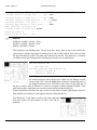
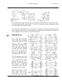
There are some drawings in the C:\autosd\Bonus folder that you may find useful. The drawing
sizes are 24" x 36" and the scale is 1" = 1'-0.
CHARTS.DWG: This drawing has bolt length and bolt values, minimum edge distance, usual
gages for angles, minimum weld sizes, pipe dimensions and C and MC dimensions.
FRACTION.DWG: This drawing is used to convert decimals of an inch or of a foot to
fractions.
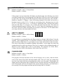
KEYBOARD CARD.DWG: This is a drawing of a keyboard layout showing the location of
the custom characters.
WSHAPES.DWG: This is a drawing that shows the dimensions for W4 - W44 and minimum
and maximum rows.
13TH EDITION BOLT VALUES.DWG: This drawing list ASD and LRFD bolt values from
AISC 13th edition.
These drawings are in the C:\autosd\menus folder. The drawing sizes are 24" x 36" and the
scale is 1" = 1'-0.
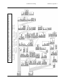
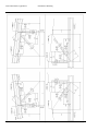
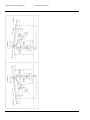
PULLDOWN MENU DIAGRAM.DWG: This drawing shows the layout of all commands in
the AutoSD pulldown menu.
RIBBON MENU DIAGRAM.DWG: This drawing shows the layout of all commands in the
AutoSD ribbon menu.
Minimum screen resolution for displaying dialog boxes is 1280 x 960
iii
AutoSD Steel Detailing
QUICK START
Read this first.
STEP 1: Installing the program.
If you are installing AutoSD for AutoCAD LT, you will need to install one of the Lisp
Enablers. Go to www.autosd.com/support.htm for a link to find where to purchase this
product.
Updating an older version of AutoSD Steel Detailing:
You should uninstall the current copy of AutoSD Steel Detailing first. Uninstalling AutoSD
will not remove any drawings or customer configurations that you have created.
Windows XP: From the task bar pick Start, Settings and Control Panel. Double click on Add
or Remove Programs in the Control window.
Windows 7: From the task bar pick Start and Control Panel. Click on Uninstall a program in
the Control Panel window.
Windows 8 & 8.1: Change to the desktop screen. Right click on the Windows icon and pick
Control Panel. Click on Uninstall a program in the Control Panel window.
Select AutoSD Steel Detailing XX, where XX is the version number and pick Uninstall.
Note: If you have customized your autosd.dwt template file located in your AutoSD\support
folder you will need to save it to another folder or disk or rename it before un-installing
AutoSD. After installing AutoSD, copy your old autosd.dwt template file back into your
AutoSD\support folder.
All files will not be removed. Some files and folders will remain. Do not delete the remaining
files and folders. Install AutoSD over the existing files.
Insert the CD-ROM into your CD-ROM drive and if the installation does not start, choose
START, RUN. Type X:\AUTOSD_SETUP where X is your CD-ROM drive letter. Follow the
on-screen prompts.
STEP 2: Installing the hardware lock.
After Setup is finished:
Attach the USB hardware lock to a USB port.
STEP 3: Configure AutoCAD or BricsCAD.
Start AutoCAD or BricsCAD. See appendix A for complete instructions on setting the support
file search path, template location and loading the menu. If you are using AutoCAD 14, close
AutoCAD and reopen it after setting the support file search path and before loading the menu.
iv
AutoSD Steel Detailing
Note: If you are updating an older version of AutoSD you must unload the AutoSD menu and
reload it. See appendix A for instructions on loading the AutoSD menu.
STEP 4: Configure AutoSD.
After configuring AutoCAD and loading the AutoSD menu, select the AutoSD pulldown menu
and Customer Configuration. Select Detail variables. Select Unnamed and pick Edit. Change
the settings in the dialog boxes as needed and select OK. Select Color list. Select AutoSD from
the list of names and pick Edit. Use the dialog box to set each color by picking on the color of
the item to be changed. Colors for weld symbols are set in the Weld Menu dialog box. Pick
OK to close the Setting Colors dialog box. You can rename the file names and add more
configurations if needed. Pick OK again to exit the configuration.
STEP 5: Starting AutoSD.
Start AutoCAD or BricsCAD. If you are using AutoCAD LT you need to use the Lisp enabler
desktop icon to start AutoCAD LT.
Select File > NEW. Select "Use a Template" and select the autosd.dwt template. It is in your
C:\autosd\support folder.
Pick AutoSD > Format > SETUP or AutoSD I > Utilities > SETUP.
Select a configuration from each of the four boxes.
Select AutoSD for Detail Variables, Unnamed - 24x36 for Shop bill, None for Material list and
AutoSD for Color list and pick OK.
In the Setup box, accept the defaults which are: Architect for Unit type 1 = 1’ for Drawing
scale, D - 24 x 36 for drawing size, horizontal for paper size and AutoSD.
Pick OK and the drawing is created.
Pick File > Save and save the drawing.
You can start detailing now.
A folder called C:\AUTOSD\CUSTOMER is created by the installation program. Where C: is
the drive you installed AutoSD on and AUTOSD is the name of the folder you chose to install
AutoSD in. You can use the shop bill drawings in this folder, (CVSPro.dwg, 24x36BOM.dwg
and 11x17BOM.dwg), to create your own shop bill. Open the drawing, change the name in the
title box, save and close the drawing.
Uninstalling AutoSD.
Open the Control Panel and pick Uninstall programs. Scroll down the list of programs until
you find AutoSD Steel Detailing 2015. Select it and pick uninstall.
v
AutoSD Steel Detailing
vi
AutoSD Steel Detailing
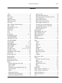
Contents
TABLE OF CONTENTS
AutoSD STEEL DETAILING ............................... i
QUICK START ................................................... iv
TABLE OF CONTENTS ...................................... 1
Chapter 1 - Introduction ........................................ 7
MENUS............................................................. 7
FT.IISS or II.SS ................................................ 7
POSITIVE AND NEGATIVE .......................... 8
FT-II*SS ........................................................... 8
ENTER .............................................................. 8
FILE NAMES ................................................... 8
ROTATION .................................................... 10
SCALE ............................................................ 10
Dwg to SDS/2 Dxf .......................................... 11
STARTING A NEW DRAWING... ............... 11
SETTING UP .................................................. 11
TEXT HEIGHT and PLOT SCALES ............. 13
FOLDERS ....................................................... 14
CUSTOMER CONFIGURATION PROGRAM
......................................................................... 14
EDITING A CONFIGURATION................... 15
COUNTRY ................................................. 17
BOLTS ........................................................ 18
FLAT BARS & PLATES ........................... 18
STANDARD SHEAR BARS ..................... 19
STANDARD CLIPS ................................... 20
BEAMS ....................................................... 21
COLUMNS ................................................. 24
EDITING A COLOR CONFIGURATION .... 24
LINE WEIGHTS ............................................ 26
ARROWHEADS ............................................ 26
Chapter 2 - Erection Tools .................................. 27
ANCHOR BOLT SIDE VIEW ....................... 27
BEAM LINES w/DESC ................................. 27
BEAM ON PLATE w/AB .............................. 28
BEARING PLATE EDGE VIEW .................. 28
BRACE LINES w/DESC ................................ 28
BLOCK WALL SECTION............................. 28
BRICK w/BLOCK WALL SECTION ........... 29
BRICK WALL SECTION .............................. 29
BLOCK WALL PLAN VIEW........................ 29
BRICK w/BLOCK WALL PLAN VIEW ...... 30
BRICK WALL PLAN VIEW ......................... 30
COL BASE PLATE w/AB ............................. 30
COLUMN w/BOLT PATTERN ..................... 31
DECK EDGE VIEW ...................................... 31
ELEVATION GENERATOR ......................... 31
Main dialog box .......................................... 32
Left side and Right side sections ................ 32
Top center section ....................................... 33
Bottom center section ................................. 33
Beams .......................................................... 33
Braces .......................................................... 34
CMU wall ................................................... 34
End Views ................................................... 35
Girts ............................................................ 35
Joist ............................................................. 35
Ladders........................................................ 36
Stairs ........................................................... 36
Landing Setup ............................................. 37
Detail landing .............................................. 38
Draw plan .................................................... 38
Export stairs ................................................ 38
Column file configuration ........................... 38
Girt configuration ....................................... 39
Joist configuration....................................... 39
Draw............................................................ 39
GRID LINES w/DIM ...................................... 40
JOIST LINES .................................................. 40
JOIST SIDE or END VIEW ........................... 40
LADDERS ...................................................... 41
MARKS / SECT / TAGS ................................ 41
MEMBER ....................................................... 43
REVISION CLOUD ....................................... 43
SAFETY GATE .............................................. 44
SHAFT OPENING ......................................... 44
STAIR PLAN ................................................. 44
TAGS .............................................................. 45
TEXT DESCRIPTION ................................... 45
U-BLOCK SECTION VIEW ......................... 45
WOOD END VIEW ....................................... 45
Chapter 3 - Draw................................................. 47
@ LINE ........................................................... 47
2 PT VECTOR ................................................ 47
ADD STUDS .................................................. 47
ADHESIVE ANCHOR................................... 47
ANCHOR BOLT ............................................ 48
ARCHED TEXT ............................................. 48
1
Contents
AutoSD Steel Detailing
ASSEMBLY MARKS .................................... 48
BEARING PLATE ......................................... 49
BOLT CIRCLE ............................................... 49
BOLT EXPANSION ...................................... 50
BOLLARD ...................................................... 51
BOLT w/N&W ............................................... 51
CLEVIS........................................................... 51
CLIP ................................................................ 51
CRANE RAIL ................................................. 52
DISTANCE ..................................................... 52
DITTO............................................................. 52
DOOR FRAME .............................................. 52
EL. ................................................................... 53
EMBED FRAME ............................................ 53
EMBED PLATE ............................................. 54
EXTRACT BOLTS (All Drawings) ............... 54
EXTRACT BOLTS (Current Drawing).......... 54
FIND TEXT STRING..................................... 55
FLG HOLE ..................................................... 55
HOLE SIZE .................................................... 56
SLOT SIZE ..................................................... 56
LIBRARY MENUS ........................................ 57
ADD TO LIBRARY ....................................... 57
CLEAN SLIDES ............................................. 57
LEADER NOTES ........................................... 58
LINTEL (loose) .............................................. 58
LINTEL (shop attached) ................................. 58
LIST FIELD BOLTS in SHOP BILL ............. 59
MEASURE 2D LINE ..................................... 59
MULTILINE STYLE ..................................... 59
NAILER ANGLE / Chanel ............................. 60
NAILER HOLES ............................................ 61
NAILER PLATE ............................................ 61
OBJECT INFO................................................ 61
OFFSET .......................................................... 62
OFFSET w/Select (Icon has yellow
background) .................................................... 62
OFFSET & CHANGE LINE TYPE ............... 62
OSNAP ........................................................... 62
PIPE ................................................................ 63
POUR STOP (Shop Attached) ........................ 63
POUR STOP (Loose) ...................................... 63
RECTANGLE ................................................. 64
ROTATE CROSSHAIRS ............................... 64
ROOF FRAMES ............................................. 64
SCALE SHAPE .............................................. 65
SHAPES.......................................................... 65
2
Wshape.dwg .................................................... 65
SCHEDULE MAKER .................................... 66
STANDARD MTEXT .................................... 67
TAIL ............................................................... 67
TAIL or TAIL DIM ........................................ 67
TEXT STRINGS............................................. 67
TURNBUCKLE .............................................. 68
WEB HOLE .................................................... 68
WELD SYMBOLS ......................................... 68
BLOCKS ..................................................... 69
SYMBOL ONLY ........................................ 69
LEADER ONLY ......................................... 69
CLEAR ....................................................... 69
SAVE/RESTORE ....................................... 69
SETTINGS.................................................. 70
HATCH ........................................................... 70
JOIST FORMS ............................................... 70
Chapter 4 - Edit ................................................... 73
ADJUST DIMENSION .................................. 73
ARRAY .......................................................... 73
ARROWHEADS TO TICKS ......................... 73
BREAK LINE TYPE ...................................... 73
CHANGE TEXT............................................. 74
CHANGE TO PLINE ..................................... 74
COLOR ........................................................... 74
COLOR w/filter .............................................. 74
DDCOPY ........................................................ 75
DATABASE EDITOR ................................... 75
EDIT ATTRIBUTE ........................................ 75
LINE TYPE .................................................... 76
LINE WEIGHT ............................................... 76
RESET DWG SCALE .................................... 76
REPLACE DIMENSION ............................... 76
REPLACE TEXT ........................................... 77
RELOCATE TEXT ....................................... 77
Scale of Drawing ............................................ 77
SCALE OF OBJECTS .................................... 78
SCALE OF BLOCKS/SOLIDS/TEXT .......... 78
LAYERS ......................................................... 78
CHANGE OBJECT'S LAYER ................... 78
FREEZE LAYER ....................................... 78
ISOLATE LAYER ..................................... 78
SET LAYER ............................................... 79
THAW ALL LAYERS ............................... 79
Chapter 5 - Decimal & FT.IISS Calculators ....... 81
ARCS .............................................................. 81
CALC .............................................................. 81
AutoSD Steel Detailing
CAMBER ........................................................ 83
DECIMAL to FEET FEET to DECIMAL . 84
EXTEND WEIGHT ........................................ 84
LOCATE WEIGHT COLUMN ...................... 85
HANGER ........................................................ 85
LOADS ........................................................... 86
OBLIQUE TRIANGLES ................................ 86
RIGHT TRIANGLES ..................................... 86
ROLLED PLATE LENGTH .......................... 87
SECTIONAL PROPERTIES .......................... 87
SELECT DIM TO ADD ................................. 89
SELECT LINE TO ADD ................................ 89
TOTAL WEIGHT ........................................... 90
Number of risers ............................................. 90
Chapter 6 – Dimensioning .................................. 91
CUSTOM FONT ............................................ 91
DIMENSIONS ................................................ 93
DIM. TEXT................................................. 93
DIMENSIONING ....................................... 93
Arrowheads ................................................. 94
DIMENSION LINE or SINGLE LINEAR
DIMENSION .............................................. 95
CONTINUE DIMENSION ......................... 95
ARC DIMENSION ..................................... 95
ARC CONTINUE ....................................... 95
BEVEL........................................................ 95
CROSSING ................................................. 96
WORD WRAP ............................................ 96
QUICK ........................................................ 97
MULTI LINE .............................................. 97
w/Bubble ..................................................... 97
Dynamic ...................................................... 98
w/Revision .................................................. 98
Chapter 7 – Beams .............................................. 99
Cuts, Copes and Blocks .................................. 99
Flange Gage Leader Note ............................... 99
Property symbol .............................................. 99
END CONNECTIONS ................................. 100
Detail Beam .............................................. 100
Support Member ....................................... 100
Support is a Hip or Valley rafter ............... 100
Slope in degrees from horizontal .............. 100
Input skewed angle of end connection ...... 101
Connection Type ....................................... 101
Import column file data ............................. 101
Clip Connection ........................................ 101
Bevel Flanges ............................................ 101
Contents
Degrees ..................................................... 102
Loads ......................................................... 102
Bolts .......................................................... 102
“T” connection .......................................... 105
SEAT ANGLE, SEAT PLATE ................ 106
INTERNAL CONNECTIONS (MAIN and
AUX.) ........................................................... 106
Connections .............................................. 106
Left, Center, Right .................................... 107
Import connection ..................................... 108
Vertical hole spacing ................................ 111
Add Symbol for Channel .......................... 111
ANGLE BEAM ............................................ 113
FINGER SHIM PLATE ................................ 113
VERTICAL PLATES ................................... 113
WING PLATE (side view) ........................... 114
Plate Only or Plate and End View of Shape
.................................................................. 114
Plate & End View of Shape ...................... 114
Plate Only ................................................. 114
Plate & End View of Shape ...................... 115
Plate Only- on an existing W8 x 31 column
flange ........................................................ 115
Plate Only - Skewed on Sloping Beam ..... 115
STIFFENER PLATE (attached) ................... 116
STIFFENER PLATE (loose) ........................ 117
SKEWED PLATE (top internal) .................. 117
TOP VIEW (skewed connection) ................. 118
MOMENT END PLATE .............................. 119
GIRTS ........................................................... 120
SAG ROD ..................................................... 121
SPLICE PLATE (Loose) .............................. 122
SPLICE PLATE (Attached) .......................... 122
Chapter 8 - Bracing ........................................... 125
CALCULATION OF GUSSET PLATES .... 125
Dimension #A ............................................... 126
PRINTING FILE .......................................... 128
VIEWING FILE............................................ 129
LIST .GUS FILES ....................................... 130
EDIT GUSSET PLATE .............................. 130
DRAWING GUSSET PLATES ................... 130
DRAWING BRACES................................... 131
Welded Brace ................................................ 135
HSS in Frame ................................................ 136
Rod Brace ..................................................... 136
Parallel Brace Tower .................................... 137
Calculate Gusset Plate (Truss) ...................... 137
3
Contents
AutoSD Steel Detailing
Chapter 9 - Columns ......................................... 139
BASE PL EDGE VIEW................................ 141
CAP PL EDGE VIEW .................................. 141
BASE/CAP PLAN ........................................ 141
VIEW BASE/CAP FILE............................... 142
SKEWED PL TOP VIEW ............................ 142
SPLICES ....................................................... 143
EDIT COLUMN FILE .................................. 143
New ........................................................... 144
Open .......................................................... 144
Save ........................................................... 144
SAVE AS .................................................. 144
MERGE FILE ........................................... 144
Column size .............................................. 144
Elevations box ........................................... 144
Connections box........................................ 144
IMPORT GUSSET ................................... 145
CONNECTIONS .......................................... 146
(1) Clip Angle ........................................... 146
(2) Girt Angle ............................................ 146
(3) Girt WT ............................................... 146
(4) Joist Angle ........................................... 147
(6) Seat Angle ........................................... 147
(7) Seat Plate ............................................. 147
(8) Split T .................................................. 148
(9) Wing Plate ........................................... 148
(10) Stiff Plate ........................................... 149
(11) Holes.................................................. 149
(12) Flange Plate ....................................... 149
(13) Gusset Plate ....................................... 150
(14) Saddle ................................................ 150
(15) Stub.................................................... 150
Chapter 10 – Shop Bill ...................................... 151
CREATING THE SHOP BILL .................... 152
CONFIGURING SHOP BILL ...................... 153
Title block configuration............................... 156
ATTRIBUTES vs. TEXT ............................. 157
EDIT SUB MARK LIST .............................. 158
EXTRACT SHOP BILL ............................... 159
EXTRACT PROGRAM ............................... 159
EXTRACT for EJE using Attributes ........... 161
EXTRACT for EJE using Text ..................... 162
EXTRACT for Fabtrol using Attributes ....... 162
EXTRACT for Fabtrol using Text ................ 163
FabSuite *.kss file ......................................... 164
COMPILE QUANTITIES From ALL
DRAWINGS ................................................. 164
4
EXTENDING WEIGHT ............................... 165
MATERIAL LIST ........................................ 167
Chapter 11 - Trusses ......................................... 169
Chapter 12 - Stairs ............................................ 171
CREATING PAN TREADS with the Tread
Builder .......................................................... 176
DIM PAN SUPPORTS ................................. 177
BOLTED TREAD END DETAIL ................ 178
PAN TREAD END VIEW ........................... 178
STAIR TREAD / RISER CALCULATOR .. 179
STAIR ELEVATION ................................... 179
PLAN VIEW OF STAIR .............................. 181
STRINGER BRACING ................................ 181
Header Beam ................................................. 182
Landing Decking........................................... 183
Landing Frame .............................................. 184
Landing Grating ............................................ 184
Landing Pan .................................................. 184
Chapter 13 - Rails ............................................. 187
RAMP or STAIR RAIL ................................ 187
WALL RAIL................................................. 190
RAIL ELEVATION ..................................... 192
LEVEL HANDRAIL .................................... 192
Detail Panel ................................................... 195
Insert Pickets ................................................. 195
Mesh Insert ................................................... 196
Chapter 14 - Ladders......................................... 199
LADDERS WITH CAGE ............................. 199
LADDERS WITHOUT CAGE .................... 200
TOP HOOP (SECT B) .................................. 201
MID HOOP (SECT C) .................................. 201
BOT HOOP (SECT D) ................................. 201
SECTIONS ................................................... 201
SECURITY GUARD .................................... 201
ERECTION ELEVATION ........................... 202
Chapter 15 – Hip & Valley ............................... 203
Chapter 16 - CNC Data ..................................... 207
MAIN MARK ............................................... 208
HOLES.......................................................... 208
ASSOCIATE HOLES with TAIL ............ 208
CHANGE FACE....................................... 208
CHANGE GAGE ...................................... 209
CHANGE OPTION .................................. 209
CHANGE SIZE ........................................ 209
CHANGE SIDE ........................................ 209
CHANGE SLOT ANGLE ........................ 209
CHANGE SLOT LENGTH ...................... 209
AutoSD Steel Detailing
CHANGE SLOT WIDTH......................... 209
CHANGE TAIL ........................................ 210
CHANGE HOLE TO SLOT ..................... 210
CHANGE SLOT TO HOLE ..................... 210
NOTE HOLES NS, FS or BS ....................... 210
REPLACE TAIL DIMENSION ................... 210
BURNS ......................................................... 210
CHANGE ANGLE ................................... 211
CHANGE BEAM END ............................ 211
CHANGE DEPTH “Y”............................. 211
CHANGE LENGTH “X” ......................... 211
CHANGE NOTCH “D” ............................ 211
CHANGE SETBACK ............................... 211
CHANGE SIDE ........................................ 211
CHANGE SURFACE ............................... 212
CHANGE TYPE ....................................... 212
CHANGE LAYER.................................... 212
CHECK DATA ............................................. 212
EDIT Data ..................................................... 213
EDIT DSTV file ............................................ 217
Gather marks ................................................. 219
Write DSTV for ............................................ 219
Write DSTV file for Clips/Tees Angles........ 219
Write DSTV file for Plates ........................... 220
Graphically Check DSTV file ....................... 221
SUB MARK .................................................. 221
Tips: .............................................................. 207
Appendix A - Installation.................................. 223
SentinelPro Drivers for Hardware Lock ....... 223
INSTALLING AutoSD STEEL DETAILING
....................................................................... 223
AutoCAD Release 14 configuration ............. 224
AutoCAD Release 2000 - 2013 configuration
....................................................................... 225
AutoCAD Release 2014 and later configuration
....................................................................... 225
Bricscad 10 and later Pro/Platinum
configuration ................................................. 226
Loading the menu ......................................... 227
AutoCAD LT configuration .......................... 228
INSTALLING the HARDWARE LOCK ..... 228
Starting a NEW drawing ............................... 229
IntelliCAD..................................................... 229
Appendix B - Support Files .............................. 233
ASD_CFG.LSP ............................................. 233
SHAPE DATABASE.................................... 233
Appendix C - Gusset Plate Details.................... 237
Contents
GUSSET PLATE INPUT FORM ................. 238
Appendix D – Truss Panel Details .................... 245
Appendix E – Stair Input Forms ....................... 249
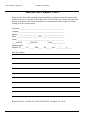
ERROR HANDLING AND REPORTING ...... 253
AutoSD 2015 Report Form ............................... 254
INDEX .............................................................. 255
5
Contents
6
AutoSD Steel Detailing
AutoSD Steel Detailing
Introduction, Chapter 1
Chapter 1 - Introduction
Welcome to AutoSD Steel Detailing.
AutoSD Steel Detailing, (AutoSD), is a steel detailing program that is designed to increase the
production of the draftsperson and act as an aid for the checker. It is assumed that you have a
working knowledge of steel detailing and AutoCAD or BricsCAD It is not designed to replace
the draftsperson but is an enhancement. The draftsperson is in control of the detailing at all
times. AutoSD will do most of the calculations and all of the drawing normally done by the
draftsperson in detailing beams, columns, bracing, gusset plates, stairs, handrails, ladders,
erection plans, sections, details and more.
MENUS
AutoSD comes with two menus, autosd.mnu and autosd.cuix. All versions of AutoCAD will
load the *.mnu file but you need AutoCAD 2010 or later to load the *.cuix file. The difference
between the two menus is the *.cuix file contains a ribbon menu and the *.mnu file does not.
The ribbon menu has two tabs, AutoSD I and AutoSD II. In this reference manual you will see
[AutoSD or AutoSD I]. “AutoSD” refers to the pulldown menu. “AutoSD I” or “AutoSD II”
refers to the ribbon menu tab. You can use the ribbon menu exclusively or just the pulldown
menu. Toolbars can be used with either menu. The AutoSD menu is an add-on to the standard
AutoCAD menu. Ribbon menus can be turned on and off with the commands RIBBON and
RIBBONCLOSE. Pulldown menus can be turned on and off with the command MENUBAR.
Set the value to 1 to turn it on and to 0 to turn it off.
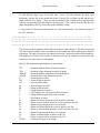
FT.IISS or II.SS
You will see this in most of the input prompts. It is the standard method of entering
dimensions. If the current dimensional unit format is set to architectural the FT.IISS format
will be used. If it is set to fractional the II.SS format will be used.
Where:
FT = number of feet
II = number of inches
SS = number of sixteenths
Using the FT.IISS format:
1'- 3 1/2" would be entered as 1.0308
6'- 10 15/16" would be entered as 6.1015
4'-0" would be entered as 4
3 1/2" would be entered as .0308
Using the II.SS format:
15 1/2" would be entered as 15.08
82 15/16" would be entered as 82.15
48” would be entered as 48
1/2" would be entered as .08
This manual uses the FT.IISS format in the examples.
7
Introduction, Chapter 1
AutoSD Steel Detailing
POSITIVE AND NEGATIVE
Many programs provide you with slide drawings or images in dialog boxes for user input.
Positive input will go in the direction shown in the slide; negative input will go in the opposite
direction from that shown in the slide.
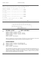
FT-II*SS
You will see this in most of the input prompts when you set up a drawing for CVSpro. It is the
standard method of entering dimensions for CVSpro. If the current dimensional unit format is
set to architectural the FT-II*SS format will be used.
Where:
FT = feet
II = inches
SS = sixteenths
Using the FT-II*SS format:
1’- 3 1/2" would be entered as 1-3*12
6’- 10 15/16" would be entered as 6-10*15
4'-0" would be entered as 45 1/2" would be entered as 5*12
3" would be entered as 3
1/2" would be entered as *12
Feet are entered followed by a minus sign.
Inches are entered as a whole number.
Fractions are entered preceded by an asterisk.
Fractions are as follows:
1/16 = *1
5/16 = *5
9/16
1/8
= *18
3/8 = *38
5/8
3/16 = *3
7/16 = *7
11/16
1/4
= *14
1/2 = *12
3/4
2’-0 = 23” = 3
1/2” = *12
= *9
= *58
= *11
= *34
13/16 = *13
7/8
= *78
15/16 = *15
ENTER
Most AutoCAD commands will repeat themselves when you press the ENTER key. This saves
time by not having to go back to the menu to pick the command each time when you are
repeating the same command over and over again such as the copy or erase command. AutoSD
takes advantage of this same time saver in many of its commands such as editing and
dimensioning, and many programs.
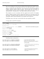
FILE NAMES
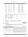
AutoSD uses several different file name extensions. All of these, except for the .cfg, bak, dat
and .sld files, are saved in the folder of the current drawing. The extensions and their uses are
as follows:
.blt
8
Bolt list extracted from your drawing.
AutoSD Steel Detailing
.bak
.cfg
.col
.csv
.dat
.dwg
.err
.gus
.imp
.kss
.lst
.mom
.nc
.pl
.sbl
Introduction, Chapter 1
Configuration bakup files.
File name
CUSTBOM.BAK
CUSTBOMM. BAK
CUSTCLR. BAK
CUSTMAT. BAK
CUSTMATM. BAK
CUSTVAR. BAK
CUSTVARM. BAK
SCHMAKER. BAK
SDS2CLR. BAK
SETUP12. BAK
WELD. BAK
Folder
C:\autosd
C:\autosd
C:\autosd
C:\autosd
C:\autosd
C:\autosd
C:\autosd
C:\autosd
C:\autosd
C:\autosd
C:\autosd\welds
Purpose
Shop bill program.
Metric shop bill program.
Color list.
Material list.
Metric material list.
Detail variable configuration.
Metric detail variable configuration.
Schedule maker
SDS/2 colors
Custom setup settings
Weld symbols
Configuration files.
File name
ASD_DATA.CFG
CUSTBOM.CFG
CUSTBOMM.CFG
CUSTCLR.CFG
CUSTMAT.CFG
CUSTMATM.CFG
CUSTVAR.CFG
CUSTVARM.CFG
DATLIST.CFG
DATLISTM.CFG
SCHMAKER.CFG
SDS2CLR.CFG
SETUP12.CFG
WELD.CFG
Folder
C:\autosd
C:\autosd
C:\autosd
C:\autosd
C:\autosd
C:\autosd
C:\autosd
C:\autosd
C:\autosd
C:\autosd
C:\autosd
C:\autosd
C:\autosd
C:\autosd\welds
Purpose
List of data files for each shape.
Shop bill program.
Metric shop bill program.
Color list.
Material list.
Metric material list.
Detail variable configuration.
Metric detail variable configuration.
Stores values for dialog boxes.
Stores metric values for dialog boxes.
Schedule maker
SDS/2 colors
Custom setup settings
Weld symbol configuration
Column files for the column program.
Shop bill extracted for E.J.E. material manager
Data files for shapes and to store defaults for some programs.
AutoCAD drawing.
Omissions from the .imp or .kss file when extracting bill of material.
Gusset plate files for the bracing program.
Shop bill extracted for E.J.E. material manager
Shop bill extracted to the kiss format for Fabtrol.
BMCONN.LST
Used to store beam end connections used in beam to
beam connection matching.
Moment end plate files for a beam connection.
DSTV format cnc file. Extension can be changed in customer configurations.
List of cap and base plates. File name is BASECAP.PL.
Shop bill extracted for viewing and printing using the Extract program.
9
Introduction, Chapter 1
.sld
.tbl
AutoSD Steel Detailing
Slides in the SLIDES folder of the drawings stored in the BLOCKS folder.
SUBMARK.TBL.
For sub marks that carry through.
If a problem occurs after editing a customer configuration file you can delete the associated
cfg file and rename the bak for that configuration to cfg.
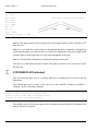
ROTATION
Some programs give you the option of rotation. All angles are measured in a counter
clockwise direction with right being 0 degrees. Up is 90 degrees, left is 180 degrees and down
is 270 degrees. Do not change this setting or the programs will not draw the pictures correctly.
Angles are entered and displayed in degrees by default. You can, however, change the units of
a drawing so degrees can be entered in any of the options offered by AutoCAD.
When drawing the end view of a steel shape, such as a wide flange, a rotation of 0 degrees is in
reference to the flange and the web will be drawn up and down. This is the position you would
normally view the end of a beam.
SCALE
There are many different scales provided that you can set your drawing up to. However, when
detailing beams, columns, or stairs you should use a scale of 1" = 1', (1:12 for metric). This is
the standard scale for detailing steel and should be used for all detail sheets. A feature of
AutoSD not found in most other CAD detailing software is that of being able to change the
scale you are drawing to. Even though you have set your drawing up to 1" = 1' as the base
scale you can use the "[AutoSD > Modify or AutoSD I > Change] > Scale of Drawing”
command and draw sections and details to a different scale. See chapter 3 for a list of some of
the programs and commands affected by the change drawing scale command.
The flange and web thickness on thin members will be exaggerated. Flanges will be drawn a
minimum of 3/4" and webs a minimum of 1/2".
CONVERTING OTHER DRAWINGS TO AutoSD
If you have a drawing that was created by software other than AutoSD and want to edit the
drawing with AutoSD certain variables need to be set in the drawing for AutoSD to work
correctly. Set up a new drawing using AutoSD and insert your old drawing as a block into it
and explode the inserted block.
If you have a DWG file created by SDS/2, SteelCAD, CVSpro or Xsteel that was imported
into AutoCAD from a dxf file you can convert it to AutoSD by opening the drawing and
running [AutoSD > Format or AutoSD I > Utilities] > Setup. Select the drawing scale and
paper size you want to use and select CVSpro, SDS/2, SteelCAD or Xsteel and pick OK.
If you have a DXF file created by SDS/2, CVSpro or Xsteel you can import it into AutoSD. If
you have an older version of SDS/2 that drew holes with an open circle in the AutoCAD DXF
10
AutoSD Steel Detailing
Introduction, Chapter 1
file then you must select the color used for the holes and it must be a different color from all
other lines, otherwise select “Ignore” for the color choices.
Start AutoCAD and start a new drawing using the autosd.dwt template. Do NOT run setup.
From the [AutoSD > Tools or AutoSD I > Utilities] menu select DXF into AutoSD and then
select Single or Multiple SDS/2 DXF file, CVSpro DXF file or Xsteel DXF file. (Multiple is
NOT available for AutoCAD LT). For a single file select the dxf file from the dialog box. For
multiple files select a single file in the folder that contains all of the files to import. Only files
with a “.dxf” extension will be imported.
After importing the dxf file the drawing is moved so the lower left corner of the border is at
the origin, (0, 0). The SDS/2 DXF file is scaled up by a factor of 12 to make the scale 1”=1’-0
and the fractions are changed back to a stacked fraction. Xsteel DXF files are scaled to fit the
margins set by the setup program for a 24” x 36” sheet.
Dwg to SDS/2 Dxf
Pulldown: AutoSD > Tools > Dwg to SDS/2 Dxf
Ribbon: AutoSD I > Utilities
This command will convert your drawing and create a dxf file of the same name as the dwg
file and save it to the same folder. All attributes will be replaced with text. Some information
in the field bolts will be lost after converting. If you want to save this information you should
make a backup copy of the dwg file to another folder before converting it.
STARTING A NEW DRAWING...
Starting a new drawing that is compatible in appearance to drawings created by SDS/2,
STEELCAD, CVSpro or Xsteel.
Select Files and New. Select "Use a Template". In the "Select a Template" window select the
autosd.dwt template and pick OPEN. If the templates are not in the window they can be found
in your autosd\support folder.
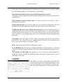
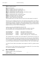
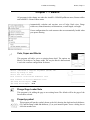
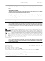
Pick [AutoSD > Format or AutoSD I >
Utilities] > Setup. Select SDS/2,
SteelCAD, CVSpro or Xsteel option at the
bottom of the setup dialog box.
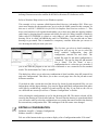
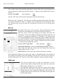
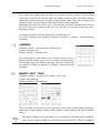
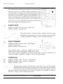
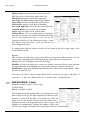
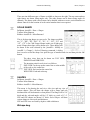
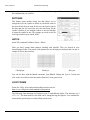
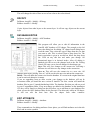
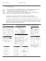
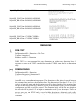
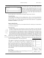
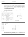
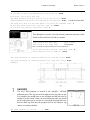
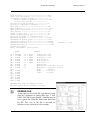
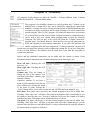
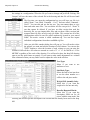
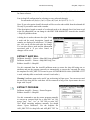
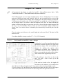
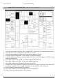
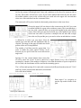
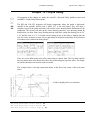
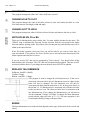
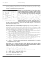
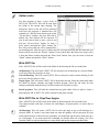
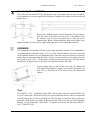
SETTING UP
Pulldown: AutoSD > Format > Setup
Ribbon: AutoSD I > Utilities
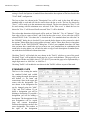
When you start a new drawing the first
thing you have to do is set the scale, units
and paper size. A dialog box is used for
11
Introduction, Chapter 1
AutoSD Steel Detailing
this purpose. Pick [AutoSD > Format or AutoSD I > Utilities] > Setup. Your next selection
will be for the units. You may pick "ARCHITECTURAL", "DECIMAL", “ENGINEERING”,
FRACTIONAL” or "METRIC”. Dimensions in architectural and fractional units will be
rounded to the nearest 1/16th, decimal units will be rounded to 2 decimal places and metric
units to the nearest millimeter. After selecting units you must pick the scale and the paper size.
All detailing should be to 1''=1' scale, or 1:12 for metric. If you need a scale not listed, select
"Type it". After picking the OK button you will be prompted to "Enter scale in inches per
foot". If you want a scale of 7/32" = 1'-0" then divide 7 by 32. You would enter .2188 as the
scale. The Plot scale would be the reciprocal x 12 = 54.8571. For a list of the scales and Plot
scales provided see page 13.
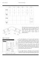
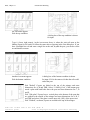
When you pick OK the drawing is set up. One border is drawn around the sheet if the border
option is checked. Save the drawing and then you may begin drawing.
Three layers are created for drawing, ASD_DRAW which is used for object lines, dimensions
and text and ASD_SECT which is used for section symbols and ASD_MARK which is used
for main marks. The color of layer ASD_DRAW
determines the color of text. You can change the colors
that are used by default by editing the colors with the
“Customer Configuration” command. See page 14 for
more information.
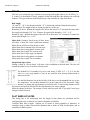
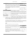
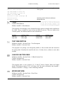
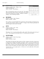
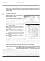
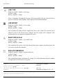
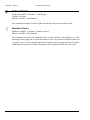
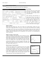
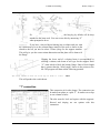
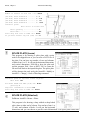
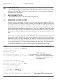
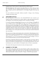
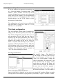
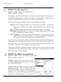
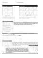
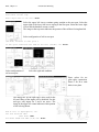
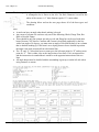
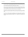
To change the drawing
area and limits of a
selected paper size pick
the “Change settings”
button. Enter the margin
sizes in real world
distances. The offset of
the border inside the
margins
should
be
greater than 0. If 0 is
used the border may not
plot if the drawing is
plotted using limits. The lower left corner of the border
will be placed at the origin of 0,0 and the border will be
inside the limits by the amount of the offset.
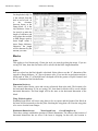
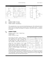
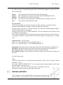
The border and drawing limits are smaller than the paper
size. The chart below lists the paper sizes and the default
drawing area.
ARCHITECTURAL and DECIMAL
PAPER SIZE
LIMITS
A-8.5x11
7.5"x10"
B- 11x17
9.8"x16"
C- 22x34
20.8"x32"
12
METRIC
PAPER SIZE
A-8.5x11
B- 11x17
C- 18x24
LIMITS
190x253
253x402
427x560
AutoSD Steel Detailing
C- 18x24
D- 24x36
D- 30x42
E- 36x48
16.8"x22"
22.8"x34"
28.8"x40"
34.8"x46"
OTHER
Introduction, Chapter 1
C- 22x34
D- 24x36
D- 30x42
E- 36x48
A4-210x297
A3-297x420
A2-420x594
A1-594x841
A0-841x1189
A4-240x330
A3-330x450
A2-450x625
A1-625x880
A0-880x1230
529x814
580x864
732x1016
884x1169
190x247
267x370
390x544
594x791
801x1139
210x300
300x420
410x595
585x850
440x1200
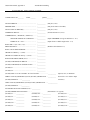
You enter the paper size and margins
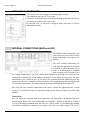
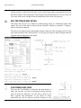
Some dimension variables are stored in the Setup dialog box. If you want to change the arrow
size, dimension text height, dimension line increment, extension line extension, extension line
offset, size of center marks/lines, dimension line gap and default text height that will be set
when you create a new drawing you must change the values here. If you want to change any of
these values after the drawing is setup you change them in the Dimension Style dialog box for
the AUTOSD dimension style.
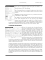
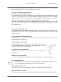
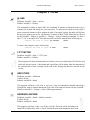
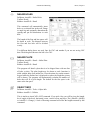
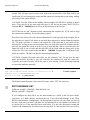
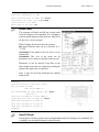
To change the font, pick the Font button. Select one of the seven
fonts shown in the icon menu. The name of the font is listed at
the bottom of each slide and will be shown to the right of the
Font button. The font selected will become the default font used
when you set up a new drawing. A different font may be saved
with AutoSD, SDS/2, SteelCAD and Xsteel.
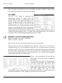
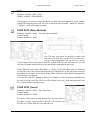
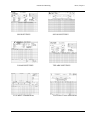
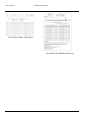
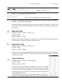
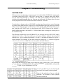
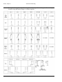
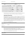
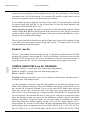
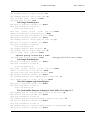
TEXT HEIGHT and PLOT SCALES
In order for the text to appear the same size when plotted using different drawing scales the
text height must change with each scale. AutoSD will make this change automatically when
you set up your drawing. The text will be 1/8'' in height when plotted. You can, however,
change this setting each time you use the text command. The chart below shows the correct
text height and plot scale for each drawing scale.
ARCHITECT
DECIMAL
METRIC
SCALE
HEIGHT PLOT SCALE
SCALE
HEIGHT PLOT SCALE
SCALE
HEIGHT PLOT SCALE
1/16''=1'
24
192.0
1''= 2000'
3000
24000.0
1:5000
15875
5000.0
3/32''=1'
16
128.0
1''= 1000'
1500
12000.0
1:4000
12700
4000.0
13
Introduction, Chapter 1
AutoSD Steel Detailing
1/8'' =1'
12
96.0
1''= 500'
750
6000.0
1:2500
7938
2500.0
5/32''=1'
9.6
76.8
1''= 250'
375
3000.0
1:1250
3969
1250.0
3/16''=1'
8
64.0
1''= 200'
300
2400.0
1:500
1588
500.0
1/4'' =1'
6
48.0
1''= 100'
150
1200.0
1:300
952
300.0
5/16''=1'
4.8
38.4
1''= 80'
120
960.0
1:200
635
200.0
3/8'' =1'
4
32.0
1''= 60'
90
720.0
1:100
318
100.0
1/2'' =1'
3
24.0
1''= 40'
60
480.0
1:75
238
75.0
5/8'' =1'
2.4
19.2
1''= 30'
45
360.0
1:50
159
50.0
3/4'' =1'
2
16.0
1''= 20'
30
240.0
1:20
64
20.0
1'' =1'
1.5
12.0
1''= 10'
15
120.0
1:12
38
12.0
ARCHITECT
DECIMAL
METRIC
SCALE
HEIGHT PLOT SCALE
SCALE
HEIGHT PLOT SCALE
SCALE
HEIGHT PLOT SCALE
1 1/4''=1'
1
9.6
1''= 1'
1.5
12.0
1:10
32
10.0
1 1/2''=1'
1
8.0
FULL
0.125
1.0
1:5
16
5.0
3'' =1'
.5
4.0
FULL
3
1.0
FULL
0.125
1.0
You can also change the height of the text and dimensions by selecting [AutoSD > Format or
AutoSD I > Utilities] > Text size and the size you want to use. 5 is normal (1/8"), 1 is half size
and 10 is double size.
FOLDERS
Folders must exist before you can put something in them.
It is a good idea that you use separate folders for each job to store your drawings. This will
keep your hard drive well organized. When you start a new drawing at the main menu give the
path to the folder where you want to save the drawing. If you want drawing number 1 to be
saved in the folder C:\SSS\9501, where "SSS" is the customer and "9501" is your job number,
the correct path for drawing number one is C:\SSS\9501\1. This will keep the drawings for one
job and customer separate from those of another.
CUSTOMER CONFIGURATION PROGRAM
Before you begin using the program you should first create a customer folder and a job sub
folder to be used to save drawing files. You can use Windows Explorer to do this. The root
folder should be the name or abbreviation of the customer you are detailing for. A sub folder
for each job will be set up inside this folder.
Example:
C:\SSS
C:\SSS\9501
The customer folder SSS
The job sub folder 9501
Warning - AutoCAD 14 only: All folder names in the path must be eight characters or less
and must not contain any spaces. Folder names must conform to DOS restrictions. This is a
14
AutoSD Steel Detailing
Introduction, Chapter 1
requirement of the extract and import programs for processing multiple drawings. Likewise,
drawing file names must also conform to the DOS restrictions of 8 characters or less.
Refer to Windows Help on how to use Windows explorer.
This example is for a customer called Superior Steel Services, job number 9501. When you
start a new drawing for sheet number one, save it to the job folder created for this customer. In
this case it will be C:\SSS\9501 for job 9501 for Superior Steel Services on drive C:. This
keeps your hard drive well organized and enables you to have more than one drawing with the
same name by keeping them in separate sub folders for each job. When AutoSD is installed a
folder called CUSTOMER is created as a sub folder of your AutoSD and has a shop bill
drawing file in it called 24x36BOM.dwg and 11x17BOM.dwg. You can edit and use these
drawings to get started. This is intended as a temporary customer folder that you can use to
save drawings in until you create your own.
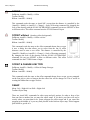
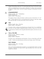
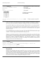
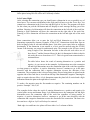
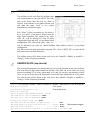
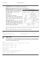
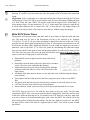
The first time you select to detail something, a
dialog box will pop up for you to select the
detail variables configuration, shop bill
configuration, material list and colors. The
default file name for the detail configuration is
“Unnamed”. The one for shop bill and material
list is “None”. The file “None” is not a
configuration but is a selection you can make if
you do not want the program to fill out a bill of materials or use a materials list for standard
marks. The default name for Colors is AutoSD.
This dialog box allows you to select any combination of detail variables, shop bill, material list
and color configurations. This allows you to have several paper sizes for one job and several
different customers.
If you had an older version that used the detvar.cfg, sbtext.cfg and material.tbl files you can
import them with the Import buttons. You can also import individual configurations from other
custVAR.cfg, custBOM.cfg, custMAT.cfg and custCLR.cfg files. If you need to edit a file or
set a different one current you will use “Customer Configuration” to do this.
After selecting the configurations to use for this drawing pick OK. The names selected will be
stored in the drawing in a block called asdcust. The next time the drawing is opened and edited
you will not be asked to select the configurations to use unless the names stored in the drawing
do not match any configuration files. This can happen if the file names were changed.
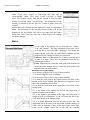
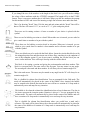
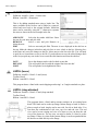
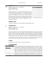
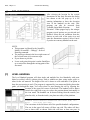
EDITING A CONFIGURATION
Pulldown: AutoSD > Customer Configuration
Ribbon: AutoSD I > Shop bill
Pick one of the buttons in the top section to display a list of configurations under “File name”
15
Introduction, Chapter 1
AutoSD Steel Detailing
The first time you open the configuration box and pick “Detail
variables” you will have one file in it called “Unnamed”. You can edit
and use this file. You can rename it or copy it with the “Save as” button
and make more files. If you have more than one file you can delete
them but you cannot delete the last one. There will always be at least
one file. If you have an older version that used the detvar.cfg file you
can import those files and use them. Older versions had separate
detvar.cfg files saved in each job folder. This version has all of the
configurations stored in one file called custvar.cfg located in your
autosd folder. The metric version is called custvarm.cfg. You can also
import and export individual configurations. Select the configuration
you want to use and pick “Set Current” to save the setting in the
drawing.
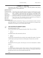
Select a configuration file and pick the EDIT button. The Customer Detail Configuration box
pops up. If you did not purchase the beam program, the Columns and Standard Clips buttons
will be disabled.
Marking style for main marks
Mark/Qty
Qty - Beam - Mark
You can enter the character that you want to use as a
separator between quantity and descriptor and
between the descriptor and mark. The default
separator is “ - ”.
Putting a check in the box for “Use QTY – REQD”
will put the text shown in the “Text for REQD” box
after the quantity separated by the separator
character.
Putting a check in the box for “Use separate marks
for Right and Left” will cause the program to put one
main mark under the piece for the right mark and one
for the left mark.
Save CNC data in drawing: Check this box to save CNC data for holes and burns.
Additional questions for holes will be asked when detailing if this box is checked. If this box is
checked tail dimensions must be from end of material, not from the clip. Enter the file name
extension you want to use for DSTV CNC files. Do not include a “.” here.
Tail all holes: Check this box to put tail dimensions to every hole. Uncheck it to put tail
dimension to the first hole only in a group.
16
AutoSD Steel Detailing
Introduction, Chapter 1
Dimensions: Select either "Ticks Only" or "Arrows and ticks". If Arrows and ticks is selected
ticks will be used for dimensions that are smaller than 2.5 times the arrow size. Arrows will be
used for dimensions that are 2.5 times the arrow size and larger.
Place dimensions outside extension lines: When dimensions are less than:
If this box is checked, dimensions smaller than the length given will be placed outside of the
extension lines.
When dimension contains fraction only: Put a check in this box if you want 1” and 2”
dimensions to be centered.
Extend dimension line: Put a check in this box if you want these dimensions to have the
dimension line extended under them when they are offset outside of the extension line.
Put Main member metric size on detail and in shop bill: If you have the drawing set up as
architectural units, put a check in this box if you need the metric size of the main members
shown in addition to the imperial size. If you have the drawing set up as metric units, put a
check in this box if you need the imperial size of the main members shown in addition to the
metric size.
Tail Symbol: Select the target or "TAIL" symbol to be placed at the left end of the detail or
check the box "Use Custom Tail note" to change the word "TAILS" in the tail symbol to the
one you type into the edit box to the right of "Note".
Print: Print a hard copy of all of the configuration settings.
Create BOM files for: The options are Fabtrol and FabSuite. Each one imports a *.kss file but
each uses a different shape designations. Choose the material management program you are
using.
File extension for EJE SMM: The options are *.csv for the newer ASCII delimited file
format and *.imp for the older fixed field file format. Choose the extension for the version of
SMM that you are using.
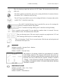
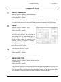
COUNTRY
The country you select will determine which data base
will be used for shapes and which design method will be
used for connections. If you choose any country other
than USA your drawing must be set up using metric units.
17
Introduction, Chapter 1
AutoSD Steel Detailing
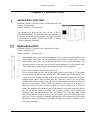
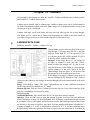
BOLTS
This box is for setting the type, diameter, bolt spacing, bolt length, when to use X SPA @ Y =
Z, (where X is the number of rows), graphics for the bolt head and edge distances for each bolt
diameter. The type, diameter and bolt spacing are also available on a per detail basis.
Bolt length:
“N” and “X”: “N” is for threads included, “X” is for threads excluded from the shear plane.
Stick through: The length of bolt to extend past the face of the nut.
Round up or down: Rounds the length of the bolt to the nearest 1/4” increment but may make
the actual stick through 1/16” less. Variance for actual stick through is -1/16”, +1/8”.
Round UP only: Rounds the length of the bolt UP to the nearest 1/4” increment. Variance for
actual stick through is -0, +3/16”.
Short slots: Putting a check in any of these boxes
will draw a short slot in the connection material.
Xdata for cnc will be saved in the piece mark.
Show short slots in internal clips on beam web:
Show short slots in wing plates on beam web:
Show short slots in split Tee on beam web:
Show short slots in clips angle on columns:
Show short slots in wing plates on columns:
Show short slots in split Tee on columns:
Shop bolted clips w/slots:
Putting a check in “Slot in beam” will draw a slot in addition to the bolt head. The slot will
contain the xdata for cnc if cnc data is being saved.
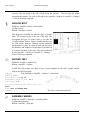
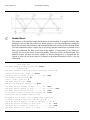
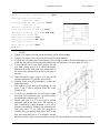
The default for X in number of rows to start using "X SPA @ Y = Z" is 8. Set this
value to a very large number if you do not want the hole spacing dimensioned as
shown to the left.
Use the Bolt diameter list on the left side of the box to set the standard bolt size to use
for connections. Use the Bolt diameter list on the right side of the box under "Edge
distance" to change the edge distance for each bolt size. To edit an edge distance select
the bolt size and pick the edit box for the edge distance you want to change.
Make the change in the box. The change is saved when you pick OK. If you pick Cancel your
changes will not be saved.
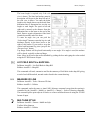
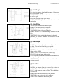
FLAT BARS & PLATES
This dialog box is for configuring how the length of bent plates are calculated and for
configuring the size of material you want to designate as Flat Bars.
Calculate Bent Plate Length: Options are to inside of bend regardless of thickness, to
centerline using a radius based on the thickness and to inside of bend for thin plates and to
centerline for thicker plates.
18
AutoSD Steel Detailing
Introduction, Chapter 1
Plates: This is for specifying the prefix used for plates. The default is “`P”.
This will be shown as "PL" in the drawing.
Bars: If you want all bars to use the prefix for plates, put a check in the box
at the top of the “Bars” section or change the prefix for bars to the one shown
for plates.
Warning! If you change the prefix for bars to `P you should set the "Format"
in "Shear Bars" to "Thick x Width".
The "Width" box lists all of the widths that will be described using the prefix
in the "Prefix descriptions with" box. Any plate that is the minimum
thickness listed or thicker and whose width is in the "Width" list will be
prefixed with the prefix shown. You can add, change and delete widths, set
the minimum thickness and change the prefix. To change a width, select the width you want to
change, make the change in the box to the right of the word “Width” and pick “Apply”.
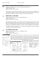
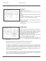
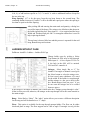
STANDARD SHEAR BARS
This box is for setting the marks for standard shear bars.
The top row contains options you can turn on or off by
checking or un-checking the option. Designation and
Gage are global settings and apply to all marks. For
example, you cannot have some marks with a gage and
some marks without a gage. Prefix and Suffix, however,
are applied separately to each bar. The row below these
options labeled "Set Order" is for arranging the order of
the components of the mark. To change the order, select
the label you want to move. The current position will be
shown in the "Position" drop down list and in the "Label
Position" box to the right. Select a new position and the label will be swapped with the one
currently in that position. The row below "Set Order" shows how the mark is constructed and a
sample of what the mark will look like.
Checking "Designation" will include the text that is shown in the designation pop down list in
the mark The text shown in the list can be changed using the "Add", "Chg" and "Del" buttons.
If you delete a designation you will be deleting a description. If you add a designation you will
be adding a description. The description for the new designation will be copied from the
current description. Different descriptions can have the same designation. The number to the
right of the designation indicates which description in the designation list you are editing.
When editing an existing mark or creating a new mark you start with the designation list. The
designation does not have to be part of the mark but is used to separate the descriptions from
one another.
19
Introduction, Chapter 1
AutoSD Steel Detailing
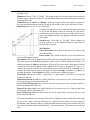
"Format" is where you select which you want listed first, the thickness or the width. This
setting is for all descriptions of standard shear bars and the descriptions of flat bars listed in the
"FLAT BAR" configuration.
The bar or plate size shown in the "Description" box will be used in the shop bill when a
standard mark is used and will also be used to draw the bar to scale. The bar size shown for
"Size 1" will be used up to the maximum rows selected. The bar size shown for "Size 2" will
be used starting with the minimum rows selected. If the "Max rows" is blank the bar size
shown for "Size 1" will be used for all rows and "Size 2" will be disabled.
The values that determine which mark will be used are "Bolt dia", "No. of Columns", "Gage
from edge of bar to center of hole" and if the bar has slots or not. A bar with slots will be
selected ONLY if the "Use short slot" is checked and “Use standard shear bar with slots” in
the “BEAMS” dialog box is checked. If you want the holes drawn as slots you need to check
the options "Show short slots in wing plates on beams" and/or "Show short slots in wing plates
on columns" in the "BOLTS/EDGE" dialog box. If all of your standard shear bars use short
slots and none have round holes and you want to use your standard bars in combination with
round holes in wing plates you will need to make a copy of each description of standard bars,
one with short slots and one without short slots.
Checking "Prefix" will include the text shown in the "Prefix" edit box as part of the mark.
Checking "Gage" will include the listed gage for a given web thickness. The gage will be in
the format of inches and 16th's where 2 1/4 is 204. If you want the gage to be represented by a
single digit enter it as .0001 for 1 or .0005 for 5.
Checking "Suffix" will include the text shown in the "Suffix" edit box as part of the mark.
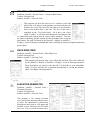
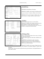
STANDARD CLIPS
This box is for creating the marks
for standard bolted and welded
clips, setting the angle descriptions
and default c/c for beam end
connections. Start in the upper left
corner with the designation. The
text shown in the designation list
can be changed using the "Add",
"Chg" and "Del" buttons. If you
delete a designation you will be
deleting a description. If you add a
designation you will be adding a
description. The description for the
new designation will be copied
from the current description.
Different descriptions can have the
same designation. The number to
the right of the designation
20
AutoSD Steel Detailing
Introduction, Chapter 1
indicates which description in the designation list you are editing. The designation does not
have to be part of the mark but is used to separate the descriptions from one another. The
values that determine which mark will be used in the beam program are "Bolt dia", "C/C" in
OSL", "Shop Weld", "Shop Bolt" and "Staggered".
The angle size shown for "Size 1" will be used up to the maximum rows selected. The angle
size shown for "Size 2" will be used starting with the minimum rows selected. If the "Max
rows" is blank, the angle size shown for "Size 1" will be used for all rows and "Size 2" will be
disabled. The angle size configured will be used in the shop bill when a standard mark is used
and will also be used to draw the clip to scale. The first leg size will be the outstanding leg.
The second leg size will be placed against the web of the beam. You can enter the angle
description manually or pick "Select" and choose an angle from the list that pops up.
The next row contains options you can turn on or off by checking or un-checking the option.
Designation and Gage are global settings and apply to all marks. For example, you cannot
have some marks with a gage and some marks without a gage. Prefix and Suffix, however, are
applied separately to each angle. The row below these options labeled "Set Order" is for
arranging the order of the components of the mark. To change the order select the label you
want to move. The current position will be shown in the "Position" drop down list and in the
"Label Position" box to the right. Select a new position and the label will be swapped with the
one currently in that position. The row below "Set Order" shows how the mark is constructed
and a sample of what the mark will look like for a 3 row clip.
Checking "Designation" will include the text that is shown in the designation pop down list in
the mark. Checking "Prefix" will include the text shown in the "Prefix" edit box as part of the
mark. Checking "Gage" will include the listed gage for a given web thickness. The gage will
be in the format of inches and 16th's where 1 7/8 is 114. If you want the gage to be represented
by a single digit enter it as .0001 for 1 or .0005 for 5. If you are not using slots in the clip or
your mark requires the actual gage then check the box by "Use Actual Gage". Checking
"Suffix" will include the text shown in the "Suffix" edit box as part of the mark.
If the clip is shop welded, pick "Shop weld". If the clip is shop bolted, pick "Shop Bolt". If the
shop bolts are staggered, check the box by "Staggered".
The last items are the Default C/C for beam end connections. These settings should match one
of the "C/C in OSL" that you set for one of the clips. Select OK when you have finished all of
the changes.
BEAMS
Bevel Flanges:
Enter values for “Bevel Flanges for field welds”.
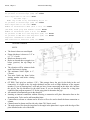
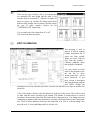
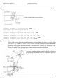
Shop bolted Clips and Stiff:
21
Introduction, Chapter 1
AutoSD Steel Detailing
#1 & #2 are the gages
for shop bolted clips. #3
is the setback from the
heel to end of web. #4
is
the
clearance
between beams at the
flange block. #5 is the
clip thickness. Enter 0
for item #6 to make the
length of stiffeners and
wing plates that welded
to both flanges equal to
beam depth minus 2
times flange thickness.
Otherwise the length
will be shortened by the
amount you enter.
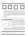
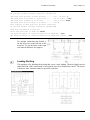
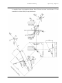
Blocks
Style:
This applies to level beams only. Choose the style you want by picking the image. If you are
saving CNC data, burn data for blocks will be saved with the block length dimension.
Depth:
Here you select how the block depth is calculated. Select either to use the “k” dimension of the
support or flange thickness, “tf”, plus a clearance value. If you use the second option and put a
check mark in “Min “k” of blocked beam” the depth will be the greater of tf plus clearance and
the “k” dimension of the blocked beam.
Dimension blocks to:
This controls where blocks, copes and cuts are referenced from at the ends. The location is for
the horizontal dimension. If you are saving CNC, burn data for blocks will be saved with the
horizontal dimension. The burn length will be the same as the horizontal dimension of the
block.
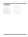
Wing PL block option:
Extending beam block will cause wing plates to be cut square and the length of the block on
the beam will be increased to clear the plate. Notching the wing plate will cause the wing plate
to be cut to clear the beam flanges.
Horizontal dimension are:
Work length is at:
Overall length is at:
These three settings establish the location of control dimensions. The setting of the location of
horizontal dimensions has no effect if the beam is slopping. In that case, the location is
22
AutoSD Steel Detailing
Introduction, Chapter 1
determined by the direction of the slope. Horizontal dimensions will be above beams slopping
down to the right and below beams slopping up to the right.
Conn for end of beam w/holes in web:
Clearance for non-standard shear bar:
This clearance will be used if you do not have a standard shear bar configuration for the bolt
size in use. The clearance can be (1) from centerline of supporting web or the face of a column
flange or (2) from the face of support. If a standard shear bar configuration can be used, the
end clearance is the gage of the shear bar minus the end of beam edge distance.
Shear bar configurations you can have standard marks for bars with round holes or bars with
short slots. Put a check in the box “Use standard shear bar with slots” to use the mark for the
bar with short slots.
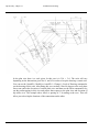
Extension and tails at left end:
This controls where tail or running dimensions and the extension line for the overall length are
referenced from at the left end. You can have both to beam, both to clip or extension to clip
and tails to beam.
Minus dimensions framing into beams:
This determines if you want to give an extra 1/16" clearance at the end of a beam with clips
when framing into a beam web.
Beams sloping up to the right:
For this condition you select whether tail dimensions come from the left
end of the beam along the top flange or the bottom flange. If you are
saving CNC the default is bottom flange.
Use max rows in end connection:
Check this if you want to use maximum rows in all beam end
connections.
Dimension clip edge distance:
Check this if you want to put a dimension to the bottom edge of end connection angles.
Show beam properties:
Check this if you want to put this symbol showing the depth and web thickness, (W),
and the flange width and thickness, (F), under the main mark.
Show support member size:
Check this if you want to put the support member size at the end of the beam detail.
Show loads on end of beam:
Check this if you want to put the loads at the end of the beam detail on a layer called LOADS.
23
Introduction, Chapter 1
AutoSD Steel Detailing
Grade of steel:
Select the grade of steel that you want as the default for Angles, Channels, Flange shapes,
Plates/Bars, Pipes and Tubes. Enter the grade for studs.
COLUMNS
This box is for setting the parameters for
dimensioning columns. It controls where the
overall length and tails are dimensioned to, the
location of the overall length, the symbol to be
used for finishing each end of the column and
whether to put the mark at the end of the
description line or not. “Connection plate to Beam
flange” controls the gap between the beam flanges
and the horizontal plates that will be welded to the
column when you save the beam to column file while detailing the beam. If you put a check in
“Extend wing plates through Tubes” or “Extend wing plates through Pipes”, all non-skewed
wing plates will be detailed going through the tube or pipe column.
EDITING A COLOR CONFIGURATION
Pulldown: AutoSD > Customer Configuration
Ribbon: AutoSD I > Shop bill
Pick Color list, select one of the names under “File name” and pick Edit.
The first time you open the configuration box and pick “Colors list” you will have 5
configuration files in it. You can edit and use these files. You can rename them or copy them
and make more files. If you have more than one file you can delete them but you cannot delete
the last one. There will always be at least one file. All of the color configurations are stored in
one file called custCLR.cfg located in your autosd folder. You can also import individual
configurations from other custCLR.cfg files.
Select a color configuration file and pick the
EDIT button. The Setting Colors Configuration
box pops up.
These files store the colors for dimension lines,
extension lines, dimension text, section labels,
text, holes, hidden lines, object lines, Main
marks, Grab Rails Column Grid text, Column
Grid bubble, Column Grid line, Color toolbar
and Line toolbar. The color of layer
ASD_DRAW is used to control the color of text, the layer ASD_SECT is used for the color of
section labels and the layer ASD_MARK is used for the color of main marks.
24
AutoSD Steel Detailing
Introduction, Chapter 1
Substitute for Color toolbar: The color used for the Color and Line toolbars are controlled
by these settings. The actual color of the icons in the toolbars will not change but you can vary
the color used by each icon. The color used by the Red icon, for example, can be changed to
any shade of red or any other color.
To change a color, select a color swath to display the color choices. Pick a color and pick OK.
The default color configuration files copied to your AUTOSD folder when AutoSD is installed
are AutoSD, CVSpro, SDS/2, SteelCAD and XSteel. These are just arbitrary file names and
have no association with the color configuration when importing DXF files into AutoSD for
CVSpro, SDS/2 or XSteel. You can rename these files as you like.
Save colors for importing DWG’s from:
Below the color choices is a row of check boxes. When you import a DXF file using the
command “DXF into AutoSD” the colors of some of the objects will be changed to match the
colors in the configuration. You can change the colors in these configuration files by putting a
check in the box for CVSpro, SDS/2, SteelCAD or XSteel.
When you pick OK, the colors will be saved to the file custCLR.cfg for the file name selected
in the Color list box and to any and all names that are checked.
The colors used for importing DXF files are saved in the following files.
File name
Configuration use
CFG-SDS2.LSP
SDS/2
CFG-CVS.LSP
CVSpro
CFG-SCAD
SteelCAD
CFG-XSTL.LSP
Xsteel
Exception:
The file CFG-SDS2.LSP for SDS/2 is NOT used for converting colors when importing dxf
files from SDS/2. It is only used to set the colors for detailing when you run [AutoSD >
Format or AutoSD I > Utilities] > Setup and select the SDS/2 option.
Converting colors when importing dxf files from SDS/2 is
handled by the command [AutoSD > Tools or AutoSD I >
Utilities] > DXF into AutoSD > Configure SDS/2 colors. The
dialog box shown to the left is used to configure the colors.
The list under SDS/2 is the color of the object in the dxf file.
The colors under “To AutoSD” is what each color will be
changed to for each type of object. Solids are for arrowheads.
Names for specific line types under “Line types” will be
changed to the name in the list next to each name. The color
here will override the colors shown above Line types.
25
Introduction, Chapter 1
AutoSD Steel Detailing
After making changes, pick OK to save those changes. Picking Cancel will remove all changes
made to colors and line weights.
LINE WEIGHTS
At the bottom of the customer colors configuration dialog box
is a button that opens a line weight dialog box shown to the
right. This option is for setting line weights for plotting lines
of different thicknesses by line weight. Any settings here will
override line weights based on color when plotting.
Putting a check in the box for “Enable Line weights” will
cause the program to use the values set here for line weights.
Un-checking the box will disable this feature.
After making changes, pick OK to save those changes.
Picking Cancel will remove all changes.
ARROWHEADS
Arrowheads in previous versions of AutoSD used a block called Dimarrow. This has been
changed. You will need to open the Dimension Style dialog box, pick the Lines and Arrows
tab and set the 1st, 2nd and Leader arrowhead to Closed filled. You may select any of the
arrowhead types from the list but Closed filled will look the same as the old Dimarrow block.
If you do not change this setting your arrowheads my not be the correct color.
26
AutoSD Steel Detailing
Erection Tools, Chapter 2
Chapter 2 - Erection Tools
ANCHOR BOLT SIDE VIEW
Pulldown: AutoSD > Erection Tools > Anchor Bolt Side View
Toolbar: Erection Tools
Ribbon: AutoSD I > Erection Tools
This program will draw the side view of any of the six
different anchor bolts. The insertion point is the underside of
the washer and the bolt can be rotated to any angle. The scale
is affected by the [AutoSD > Modify or AutoSD I > Change]
> Scale of Drawing command.
BEAM LINES w/DESC
Pulldown: AutoSD > Erection Tools > Beam Lines w/Desc
Toolbar: Erection Tools
Ribbon: AutoSD I > Erection Tools
This program draws a line with several options. You can put a moment symbol, a solid
filed triangle, at the ends. You can include the camber with a custom prefix. You can
include shear studs with a custom bracket character on each side of the number. The
stud count can be on the same side of the line as the member size or the opposite side.
The member size is always printed, the camber and stud count are optional.
Pick 1st end of beam or [Select line] <Select line>:
Pick a point to draw just one beam from point to point or press Enter or “S” and enter
to draw multiple beams between existing lines. The member size will be placed at the
center of the line. Dimensions from beam to beam can be placed automatically for the
multiple beam option. Three existing lines are required to start if you are drawing
multiple beams. Select a line at each end of the beam for a start and stop point. They do
not have to be parallel. Select a third line parallel to the beam to be drawn as a
reference for the first beam and select which side of this reference line to draw the
beams. The program will continue to ask for the distance to the next beam, the offset at
the 1st end and the offset at the 2nd end. A positive offset is for a cantilevered
condition. Enter the dimensions and select the member size of the next beam. When
asked for the distance to the next beam you can enter 0, (zero) to end the command or
press Ctrl C or Esc to stop the command. All beam lines will be placed on a layer called
BEAM. The scale is affected by the [AutoSD > Modify or AutoSD I > Change] > Scale
of Drawing command.
27
Erection Tools, Chapter 2
AutoSD Steel Detailing
BEAM ON PLATE w/AB
Pulldown: AutoSD > Erection Tools > Beam on Plate w/AB
Toolbar: Erection Tools
Ribbon: AutoSD I > Erection Tools
This program will detail the end view
and web view of a beam sitting on a
bearing plate with anchor bolts showing
the projection, grout, bolt length, hook
length, bolt diameter, hole pattern and
plate size. This detail is used on anchor
bolt setting plans. You can use any of
the six anchor types shown in “Anchor
Bolt Side View” on page 27 plus an
expansion anchor and an epoxy anchor.
The scale is affected by the [AutoSD > Modify or AutoSD I > Change] > Scale of
Drawing command.
BEARING PLATE EDGE VIEW
Pulldown: AutoSD > Erection Tools > Bearing Plate Edge View
Toolbar: Erection Tools
Ribbon: AutoSD I > Erection Tools
This program draws the sectional end view of a typical bearing plate used for joists or beams
when bearing on a masonry wall. You enter the plate width and stud length. You can have one
or two studs. No dimensions will be shown. The scale is affected by the [AutoSD > Modify or
AutoSD I > Change] > Scale of Drawing command.
BRACE LINES w/DESC
Pulldown: AutoSD > Erection Tools > Brace Lines w/Desc
Toolbar: Erection Tools
Ribbon: AutoSD I > Erection Tools
This program will draw a line to represent a brace and place the member size at the center of
the line and an option to place a solid filed triangle moment symbol at the ends. Select a
member size and enter an offset at each end. A negative offset will pull the brace back from
the selected point. Select a point at each end of the brace for a start and stop point. All
information will be placed on a layer called BRACE. The scale is affected by the [AutoSD >
Modify or AutoSD I > Change] > Scale of Drawing” command.
BLOCK WALL SECTION
Pulldown: AutoSD > Erection Tools > Block Wall Section
Toolbar: Erection Tools
28
AutoSD Steel Detailing
Erection Tools, Chapter 2
Ribbon: AutoSD I > Erection Tools
This program draws a cross section of a 4", 6", 8" or 12", (100mm, 150mm, 200m and
310mm), block wall. The first point you pick will be a corner point of the first whole block on
one face. The second point may be above or below the first point. The third point picked
determines if the face location picked was the right or left side. The blocks are drawn 7 5/8",
(193.7mm), tall with a 3/8", (9.5mm), mortar joint. The scale is affected by the [AutoSD >
Modify or AutoSD I > Change] > Scale of Drawing” command.
BRICK w/BLOCK WALL SECTION
Pulldown: AutoSD > Erection Tools > Brick w/Block Wall Section
Toolbar: Erection Tools
Ribbon: AutoSD I > Erection Tools
This program is similar to Block Wall Section above but combines brick and block into one
program to draw a cross section of the wall. You input the total thickness of the wall. The
scale is affected by the [AutoSD > Modify or AutoSD I > Change] > Scale of Drawing”
command.
BRICK WALL SECTION
Pulldown: AutoSD > Erection Tools > Brick Wall Section
Toolbar: Erection Tools
Ribbon: AutoSD I > Erection Tools
This program draws the cross section of a brick wall. The first point you pick will be a corner
point of the first whole brick. The second point may be above or below the first point. The
third point picked determines if the face location picked was the right or left side. The brick
are drawn 3 3/4", (95.25mm), wide with a 3/8", (9.5mm), mortar joint. 3 brick equals one
block in height. The scale is affected by the [AutoSD > Modify or AutoSD I > Change] >
Scale of Drawing command.
BLOCK WALL PLAN VIEW
Pulldown: AutoSD > Erection Tools > Block Wall Plan View
Toolbar: Erection Tools
Ribbon: AutoSD I > Erection Tools
This program draws the plan view of a 4", 6", 8" or 12", (100mm, 150mm, 200m and 310mm
block), block wall. The first point you pick will be a corner point of the first whole block at
one end of the wall. The second point will be the corner point at the other end of the block
wall. The third point determines which side of the line between the first two points the blocks
are on. The blocks are drawn 15 5/8" long with a 3/8" mortar joint. The scale is affected by the
[AutoSD > Modify or AutoSD I > Change] > Scale of Drawing command.
29
Erection Tools, Chapter 2
AutoSD Steel Detailing
BRICK w/BLOCK WALL PLAN VIEW
Pulldown: AutoSD > Erection Tools > Brick w/Block Wall Plan View
Toolbar: Erection Tools
Ribbon: AutoSD I > Erection Tools
This program is similar to Block Wall Plan View above but combines brick and block wall
plan view into one program. You input the total thickness of the wall. The scale is affected by
the [AutoSD > Modify or AutoSD I > Change] > Scale of Drawing command.
BRICK WALL PLAN VIEW
Pulldown: AutoSD > Erection Tools > Brick Wall Plan View
Toolbar: Erection Tools
Ribbon: AutoSD I > Erection Tools
This program draws the plan view of a brick wall. The first point you pick will be a corner
point of the first whole brick at one end of the wall. The second point will be the other end of
the brick wall. The third point determines which side of the line between the first two points
the bricks are on. The bricks are drawn 3 3/4" wide, 7 5/8” long and with a 3/8" mortar joint. 2
brick equals one block in length. The scale is affected by the [AutoSD > Modify or AutoSD I
> Change] > Scale of Drawing command.
COL BASE PLATE w/AB
Pulldown: AutoSD > Erection Tools > Col Base Plate w/AB
Toolbar: Erection Tools
Ribbon: AutoSD I > Erection Tools
This program will detail the plan view and section view of a column base plate
with anchor bolts showing the projection, grout, bolt length, hook length, bolt
diameter, hole pattern and plate size. This detail is used on anchor bolt setting
plans. You can use any of the six anchor types shown in “Anchor Bolt Side
View” on page 27 plus an expansion anchor and an epoxy anchor.
The dimensions for the plate are entered in the
dialog box to the left where they can be read
from the file for other details. The scale is
affected by the [AutoSD >
Modify or AutoSD I >
Change] > Scale of
Drawing command.
30
AutoSD Steel Detailing
Erection Tools, Chapter 2
COLUMN w/BOLT PATTERN
Pulldown: AutoSD > Erection Tools > Column w/Bolt Pattern
Toolbar: Erection Tools
Ribbon: AutoSD I > Erection Tools
This program will draw the end view of a column to scale and
place a line at 45 degrees in the quadrant you select and place the
member size on the top side of the line and up to two reference
notes on the bottom side of the line. The size of this text is
controlled by the “Text scale factor”. All of this is on a layer
called “Column”. It will draw and dimension a bolt pattern with
or without base plate and put this on a layer called “Anchors”. You have
the option of drawing just the column, just the description line or just the
bolt pattern. The scale is affected by the [AutoSD > Modify or AutoSD I >
Change] > Scale of Drawing command and can be scaled up by entering a magnification factor
greater than 1.
DECK EDGE VIEW
Pulldown: AutoSD > Erection Tools > Deck Edge View
Toolbar: Erection Tools
Ribbon: AutoSD I > Erection Tools
This program will draw the edge view of floor and roof deck. The scale is affected
by the [AutoSD > Modify or AutoSD I > Change] > Scale of Drawing command.
Deck descriptions are stored in the data file US_deck.dat in your autosd\data
folder. You may edit this file to add more descriptions to it using the database
editor. See chapter 4 and Appendix B.
ELEVATION GENERATOR
Pulldown: AutoSD > Erection Tools >
Elevation Generator
Toolbar: Erection Tools
Ribbon: AutoSD I > Erection Tools
This program is for creating elevation
views for erection drawings and plan views
of stairs. The information is entered into
dialog boxes and saved to a file name and
location of your choosing. One file holds
one view. You can create elevation views
31
Erection Tools, Chapter 2
AutoSD Steel Detailing
showing beams, braces, CMU walls, columns, end view of shape on column, girts, joist,
ladders and stairs. The views can be drawn to various scales independent of the scale that your
drawing is set up to.
Input is entered in bays. One bay is the area between two adjacent columns. Bays are created
from left to right.
Main dialog box
Open: Lets you select existing elevation files to open for editing.
Save As: Lets you save a file that has not yet been saved or lets you save an existing file to a
new file name. An elevation cannot be drawn until the file is saved.
View title: This is name of the elevation view and will be printed below the elevation detail.
If you want additional text lines printed under the title, separate the text lines with the “|”
character.
Example:
COLUMN LINE A | SCALE: `4” = 1’-0”
Will be printed as:
COLUMN LINE A
SCALE: 14 = 1’-0
Note that the inch marks will be removed from the printed text.
The main dialog box is divided into 4 sections. Left side, Right side, Top center and Bottom
center.
Left side and Right side sections
These are for entering the column information of the current bay. The first edit box is for the
optional column grid. If no grid designation is needed just leave this box blank. You can have
up to three tiers. The “Piece mark” edit box is for the shipping mark of the column of the
currently selected tier. If no piece mark is needed just leave this box blank. The “Top of Col
EL” is the elevation at the top of the column or the column splice for multi-tier columns.
Picking “Del Tier 2” will delete the column for tier 2 and tier 3 and puts you back to having
only one tier. Picking “Del Tier 3” will delete the column for tier 3 and puts you back to
having two tiers. Picking “Select Size” lets you pick a column size for the currently selected
tier. Picking “Clear Size” will remove the column size for the currently selected tier. The
“Bottom of Col EL” is the elevation at the bottom of the column or the column splice for
multi-tier columns. “Orientation” lets you select how the column is viewed. “Show Cap PL”
and “Show Base PL” toggles cap and base plates on if selected and off if cleared.
Columns are optional. If a column is not required you must leave the column size blank. If you
have an elevation detail with no columns such as a stair elevation inside block walls you need
to enter a “Top of Col” elevation for one of the columns that is the height of the block walls or
higher and a “Bottom of Col EL” that is the elevation of the bottom of the lowest stair. These
elevations determine where the bay width dimension is located.
32
AutoSD Steel Detailing
Erection Tools, Chapter 2
Top center section
This is for adding or changing Bay information and entering the Main elevations.
Bay selection: Bays are numbered in sequence from left to right starting with #1. Picking
“Add” will add a bay. The “Bay #” will increase by one and you will be place in the last bay at
the right end of the elevation. You can add a bay at any time. Picking “Copy” will add a copy
of the last bay to the right end of the elevation. “Copy” will only be available when you are
viewing the last bay. Picking “Delete” will delete the current bay. To select a different bay you
can pick the “Next” or “Prev” buttons or you can pick the down arrow to the right of “Bay #”.
This will drop down the list of all bays where you can select the number of the bay you want.
All bays must have a width. Enter the width from center line of the column on the left to the
center line of the column on the right in this edit box.
Main Elevations: Elevations entered here will be dimension on the left side of the elevation
detail and apply to all bays. To enter an elevation type a number in the edit box and pick
“Add”. Repeat this until all elevations have been entered. To change an elevation pick the
elevation, type in a new number in the edit box and pick “Change”. Picking “Delete” will
remove the currently selected elevation.
EL. Note: If you want to add a note such as “First Floor” or “2nd Floor” to the detail pick the
elevation you want the note associated with and then enter the note in this edit box.
Bottom center section
This is for entering information in the current bay by picking a button that opens a new dialog
box for that member.
The following instructions are similar for Beams, Braces, CMU wall, End Views, Girts, Joist,
Ladders and Stairs.
The top of the dialog box will indicate which bay you are in by listing the column grids and
the bay number. The default will be the current bay in the main dialog box. You can change
bays by picking the “Next Bay” and “Prev Bay” buttons. Pick “Add” to add a member. A
dialog box will pop up for you to select a member size and elevation. The elevations listed
under “Main Elevations” will be in this dialog box for selecting or you can enter a different
elevation in the edit box. If the member is sloping, simply put a different elevation at each end.
The “Change” button lets you change the size and/or elevation of the currently selected
member. The “Delete” button will remove the currently selected member. The size and
elevations will be displayed in the list box.
Beams
If you have a beam attached to only one column you need to put a check in “Stub Beam” box
and select either “On Left Col” or “On Right Col” of the current bay. Next, select which side
of the column the beam is on and enter the “Length of beam” in the edit box. This is the
distance from the center line of the column to the end of the beam. If you have a beam that
extends over the top of a column you need to put a check in the “Cantilever” box. Next, select
which column the beam cantilevers and enter the “Length of beam” in the edit box. This is the
distance from the center line of the column to the end of the beam.
33
Erection Tools, Chapter 2
AutoSD Steel Detailing
You can add a note to the left and/or right ends of a beam. This can be an end reaction, piece
mark or other note. Separate the text lines with the “|” character to put multiple lines of text at
one end.
Example: 23k | 48B3
will be printed as:
23k
48B3
with the “23K” above the beam line and all other text below the beam line.
Below this is the “Orientation”. The selections available will depend on the shape of the beam.
“W” shapes will either be “Web” or “Flange” view. Channels can be toed Up, Down, NS or
FS. The image above and at the right end of Orientation will show an icon of what has been
selected.
Braces
Pick Add to add a brace to the current bay. The top and bottom elevation
for the brace are normally the top elevation of the beam it frames to.
Select the “Type” of brace by picking an icon image. Next select the
“Orientation”. The icons available will depend on the shape of the brace. If
the brace is an angle select whether it is “1 Member” or “2 Members” and
if you want a designation for the “Long Side Vertical” added to the detail
put a check in that box. If you need to add additional text under the center
of the brace put it in the “Note” edit box. Separate the text lines with the
“|” character to put multiple lines of text.
Example: (47k %%p) | 21D1
will be printed as:
(47k +-)
21D1
Work Point at Bottom: (of brace) and Work Point at Top: (of brace)
Select where the work line of the brace will intersect the beam and
column, either “Center” or “Face”.
Work Line is at: Select where the work line of the brace is located.
After making all selections for one brace pick “Add” to add another brace. The selections of
the currently selected brace will be the defaults for the new brace. Pick OK to save and close
the Brace dialog box. Pick Cancel to close the Brace dialog box without saving the changes.
CMU wall
The wall can include brick on either side. Dimension A can be
referenced from either column line and from either side of the wall.
Block widths available are 4, 6, 8, 10 and 12.
The dimension locating the wall from the column will be drawn
above the top of the wall. If you have two walls the same height
located from the same column the dimensions will overwrite. To
avoid this locate the left wall from the left column and the right wall
from the right column.
34
AutoSD Steel Detailing
Erection Tools, Chapter 2
End Views
Putting a check in the box for “Note size” will add a leader
with the member size to the detail. “Short Side Vertical” is for
the orientation of tubes. Angles and channels can be toed left
or right. Angles and Tees will have the leg or stem pointed up
or down. The dimension locating the end view can be from the
left or right column.
Girts
The left and right side of the dialog
box show an image for a “Girt line”.
If the girts extend past the column line at the left end enter a distance
for the “Girt line” under the left side image. A negative distance will
stop the girts short of the column line. The girt line information will
be available no matter which bay you are editing but will apply only
to the first and last bay of girts.
After adding a girt, select the “Object Type”. It can be a Girt, Door
or Window. The center image is changed to show which type is
selected and the type is changed in the display list. If a door or
window is selected the “Location”, Width of opening” and “Height of opening” are enabled to
the left of the display list and values must be entered for each. The location can be from the
left column or from the right column as selected under “Located from”.
After making all selections for one girt pick “Add” to add another girt. The selections of the
currently selected girt will be the defaults for the new girt. Pick OK to save and close the Girt
dialog box. Pick Cancel to close the Girt dialog box without saving the changes.
Joist
The elevations entered for each end are to the joist bearing.
The joist size is taken as a literal string for labeling. The Depth
and seat height is entered in the joist dialog box for each joist.
Remember to use the correct format for dimensions as shown at
the top of the dialog box.
After making all selections for one joist pick “Add” to add
another joist. The settings of the currently selected joist will be
the default for the new joist. Pick OK to save and close the Joist
dialog box. Pick Cancel to close the Joist dialog box without
saving the changes.
35
Erection Tools, Chapter 2
AutoSD Steel Detailing
Ladders
Under “Type” select “Caged” or “Non-caged” and “Side step” or
“Step through”. Under “View” select “Front” “Left Side” or “Right
Side”. The location can be from the left column or from the right
column as selected under “Located from”. The dimension for the
location is entered in the edit box for “Center of ladder from left
column”
After making all selections for one ladder pick “Add” to add another
ladder. The selections of the currently selected ladder will be the
defaults for the new ladder. Pick OK to save and close the Ladder
dialog box. Pick Cancel to close the Ladder dialog box without
saving the changes.
Stairs
To the right of the display list are selections for “Slope”,
“Top” and “Bottom”. The slope orientation of the stair can be
up to the left or up to the right. Changing it will change the
images shown. Select the top and bottom condition and the
image below will change to reflect your selections.
Enter any Two: For dimensions #1, #2 and #3 you only need
to enter 2 of these. Those two are subtracted from the bay
width to get the third.
Ends: Dimension #4 is from the work point at the bottom end
to the end of the stringer and #5 is from the work point at the
top end to the end of the stringer.
Elevation view of stair image:
#6 is from top of upper floor to top of frame member.
#7 is from nosing line to top of stringer.
#8 is from top of lower floor to top of frame member.
#9 is from the work point at the bottom tread to the back of the
header on the lower landing. This dimension is required even if
this is the ground floor. It can be 0.
#10 is from the work point at the upper floor to the back of the
header beam.
#11 is the depth of the landing on the left side from back of
header to back of wall member.
#12 is the depth of the landing on the right side from back of
header to back of wall member. #11 & #12 locate the face of the
CMU wall shown in the landing setup.
#13 is a global dimension used for all stairs in one bay. The
dimension can be the same as the bay width or inside distance of
CMU walls at each end of stair. If the stair frames into a floor
beam on the column center line on the left, for example,
36
AutoSD Steel Detailing
Erection Tools, Chapter 2
dimension #11 will not be used but must still be entered. You must select “None” for the
frame type in the Landing Setup in this case.
Rails: Select either Pickets or Rail or neither. If Rail is selected you need to select the number
of lines.
Treads: Select the type of Grating or Pan. The image to the right will change to reflect your
selections.
Enter the “Number of treads” in the edit box and press the enter key or tab key and the first
riser will be calculated and put in the “First riser - R” edit box as the default. You can change
it or leave it as-is.
Stair is: Either NS or FS. The image of the plan and elevation view will change to reflect
your selection.
After making all selections and entering all values for one stair, pick “Add” to add another
stair. The selections of the currently selected stair will be the defaults for the new stair. Pick
OK to save and close the Stairs dialog box. Pick Cancel to close the Stairs dialog box without
saving the changes.
Landing Setup
Pick this button to configure the landings for both right and
left side. There is only one landing configuration per elevation
view. The same configuration is used on all floors in one
elevation view. The configuration set here will be the default
for the next elevation file.
Frame location: Left side, Right side: Select the side that you
want to configure. When you have finished that side select the
other side. If you want this side configured to be the same as
the first side pick the ”Same as other side” button.
Frame type: The frame type can be built up or mitered, (“dog
leg” - shop welded to stringer) or none for framing the stringer
to a floor beam. The one you select is reflected in the Plan
input at the bottom of the dialog box. Fill out all information
for both right and left
sides.
Section: This is
enabled if you select
either built up or
mitered frame type.
This shows a section
through the frame
showing the end view
of the header beam with a CMU wall. In a built up frame the header is one side of the frame so
the header to stringer connection options are disabled. #1 is from face of CMU to back of wall
member. #2 is from top of floor to top of header. #3 is from top of wall member to top of floor.
37
Erection Tools, Chapter 2
AutoSD Steel Detailing
#4 is floor thickness. “A” is from back of header to center of holes if the frame type is mitered
and the header to stringer connection is holes.
Plan: Dimensions shown in plan for the landing. #5 & #6 are from back of frame end member
to end of wall and header members. #7 & #8 are from back of built up frame end member to
back of stringer or from back of wall member to ends of mitered stringer. Only one end at each
corner should extend past for a mitered frame, so, one dimension at each corner should be 0.
#9 & #10 are from back of stringers to edge of floor opening or face of CMU walls. #11 is
width of stairs. #12 is from edge to edge of floor opening or face to face of CMU walls. #13 &
$14 are the thickness of the CMU walls. These can be 0 for no walls. #15 is from the column
center line to the inside face of the CMU wall. The outside line of the CMU end wall is the
center of the column line. Enter 0 for #15 for no CMU wall.
The right side of the dialog box is for entering the landing member sizes and selecting which
way the wall members are toed.
Stringer to Header: Enter dimension #1, #2 & #3 to locate the holes for this connection.
Detail landing
If landings are built-up as a frame, and you have the Stairs and Rails package, they may be
detailed by picking this button. It will close the Elevation generator program and open the
Landing Frame program. The input for the landing frame will be exported for the elevation
selected and imported into the Landing Frame program.
Draw plan
Pick this button to draw a plan view of each landing. A list will be
displayed, as shown to the right, for you to select an individual plan
elevation or put a check in the box “Select all” to draw all plans.
Export stairs
If you have the Stairs and Rails package, pick this button to export all stringers in the current
bay. They can be detailed by the Stringer program. The file name for each stringer will begin
with the file name of the current open Elevation Generator file plus the bay number plus the
bottom and top elevations of the stringer.
Column file configuration
If you have the Beam and Column package you can create column files from the elevation
views. Pick the Bay that you want and then pick the “Write to column file” button under the
right side or left side column. If the column is spliced you will need to select the tier as well
and make a separate file for each tier. After selecting an existing column file to append to or
replace or creating a new column file, a configuration dialog box pops up. You can also open
this box by picking the “Column file configuration” button on the main dialog box. This box
pops up every time for you to select the proper column face but it needs to be configured only
38
AutoSD Steel Detailing
Erection Tools, Chapter 2
once or when the need requires it. If you
have girts you will need to select the
correct connection for the current
column by picking the Girt configuration
image button.
Pick OK to create the column file and
return to the main dialog box or Cancel
to abort. Picking cancel will also cause
you to lose all changes made to the
configuration.
If you have two elevation views, you
can create a single column file that
contains the connections for members in
both elevations. See the picture to the
left that represents the plan view of a
column at lines “1” and “A”. If you are
looking at line “1” the face on the left side of the column in the elevation view would be “D”.
Looking at line “A” the face on the left side of the column in the elevation view would be “A”.
After creating the column file for the first elevation view, append the results of the second
view to the existing file. The two views may be processed in either order.
Girt configuration
Pick the Girt config image button and select the proper girt to
column connection from the image icons on the left side. Enter
the dimensions for the connection and select the angle and WT
size.
Pick OK to save the settings. Picking cancel will cause you to
lose all changes made to the configuration.
Joist configuration
Select the Joist config button and select the seat type and enter
values for all options available. Pick OK to save the settings.
Picking cancel will cause you to lose all changes made to the
configuration.
Draw
This will save all changes to the file and open up the “Select
Scale” dialog box. Pick the scale you want the elevation drawn to
and pick OK. You will be prompted for the insertion point while a
box is drawn around the cross hair location. The box is the extents
39
Erection Tools, Chapter 2
AutoSD Steel Detailing
of the elevation view and will move with the cross hairs. After picking a point the box
disappears and the elevation is drawn.
GRID LINES w/DIM
Pulldown: AutoSD > Erection Tools > Grid Lines w/Dims
Toolbar: Erection Tools
Ribbon: AutoSD I > Erection Tools
This program will draw grid lines with column grid bubbles and optional dimensions between
grid lines. You draw the first grid line. The end you start with is the end the grid bubble will
be on. After the first grid line and bubble has been placed you select one side of the line for the
placement of other grid lines and bubbles and you select the location of dimensions if any are
required. After that all you input is the distance to the next line and the designation for the grid
bubble. Press ESC or enter 0 for the distance to the next grid line to end the program. Entering
the Grid mark as “150|11” will stack the text with “150“ on top and “11“ underneath. The
scale is affected by the [AutoSD > Modify or AutoSD I > Change] > Scale of Drawing
command.
JOIST LINES
Pulldown: AutoSD > Erection Tools > Joist Lines
Toolbar: Erection Tools
Ribbon: AutoSD I > Erection Tools
This program is similar to the beam lines program. This program will place joist inside a
four sided area. The boundaries of this area do not have to be square or parallel. The joist
lines will be put on a layer called JOIST. At the prompt “(FT.IISS) <Joist
spacing>/Number of equal spaces:” you can enter a real number for the spacing or the
letter N, (upper or lower case), to enter the Number of equal spaces. The spacing is
affected by the [AutoSD > Modify or AutoSD I > Change] > Scale of Drawing
command.
JOIST SIDE or END VIEW
Pulldown: AutoSD > Erection Tools > Joist Side or End View
Toolbar: Erection Tools
Ribbon: AutoSD I > Erection Tools
This program draws the side or end view
of open web joist and joist girders. Joist
sizes are (H, J or K), (LH or DLH), Girder
and Other. If “Other” is selected you will
be prompted to enter the size of the top
chord, bottom chord and web member.
40
AutoSD Steel Detailing
Erection Tools, Chapter 2
Side View: You must pick the insertion point for the bottom of the seat at the edge of support
and a point for the length of the joist before you can enter all of the variables. For the location
of the end of seat from the insertion point, seat length, location of holes, top chord extension
and bottom chord extension you can enter a length or pick a point. There are two types of top
chord extensions. The one selected will be shown with a black background.
End View: Put a check in “Show seat” if you want the seat drawn. Insertion point can be at
the top of the joist or bottom of the seat. You can select to put holes in the seat with a
dimension to them.
A reference elevation can be put on both side view and end view.
The scale is affected by the [AutoSD > Modify or AutoSD I > Change] > Scale of Drawing
command.
LADDERS
Pulldown: AutoSD > Erection Tools > Ladders/Gate
Toolbar: Erection Tools
Ribbon: AutoSD I > Erection Tools
This will display an icon menu for the selection of plan views of
ladders with and without cages for use in creating erection drawings.
The insertion point is the middle of the rung. The scale is affected by
the [AutoSD > Modify or AutoSD I > Change] > Scale of Drawing
command.
MARKS / SECT / TAGS
Pulldown: AutoSD > Erection Tools > Marks / Sect / Tags
Toolbar: Miscellaneous
Ribbon: AutoSD I > Miscellaneous
This will display an icon menu for the selection of piece mark, section marks, break lines,
north arrow, column bubble, column, AISC symbol, revision symbols and UP and DOWN
arrows.
This places attributes in the drawing for piece marking an item and giving its quantity.
There are two formats: MARK over QUANTITY and QUANTITY - BEAM - MARK. If
41
Erection Tools, Chapter 2
AutoSD Steel Detailing
you are saving CNC data the mark will also have two hidden attributes for the size and length.
If you change the size of the member or the length in the detail view you will need to change
the values of these attributes with the ATTEDIT command. The length will be in the FT.IISS
format. There is one more attribute that is left blank. When you edit the attributes the prompt
for this attribute is REF: and is used for inserting a single line reference note under the mark.
This is for drawing "break” lines. Pick the start and end points and the "break" line will be
drawn. The line will extend 1 1/2", at a scale of 1" = 1', past each point picked.
These two are for cutting sections. A letter or number of your choice is placed with the
symbol.
These two are for labeling a section or a detail. When either one is inserted, you are asked to
give a mark letter or number to be put with the symbol.
These three are for labeling a section, detail or elevation. When one is inserted, you are
asked to give a mark letter or number a sheet number and a reference number to be put
with the symbol.
These two blocks are to be used with the block below. Insert the circular block below with
the triangular points first and then insert one of these flags, attaching it to the endpoint of
one of the triangular points. If you do not want it touching the circular block you can
move it after insertion. This will keep it lined up with the circular block.
This block is for cutting a section and giving the section number and sheet number. This
block is a two part block. The outer circle is the first part. You may rotate it to any angle.
The second part is the mark and sheet number. It will always be at a rotation angle of 0.
This is the north arrow. The arrow may be rotated to any angle but the "N" will always be at
a rotation angle of 0.
This is a bubble for column line identification. You are prompted for the Grid mark. The
mark will automatically be placed in the center of the bubble. Once inserted, the bubble
may be rotated to the desired direction but the text will have a rotation of 0. Snap mode is
automatically set to end snap for easy insertion.
This bubble is for when the column line identification has at least 4 characters. The dots in
the icons represent the insertion points. Rotation is always 0. You are prompted for the
column mark. The mark will automatically be placed in the center of the bubble and will
have a rotation of 0. Snap mode is automatically set to end snap for easy insertion.
This is a bubble for column line identification where you would have a mark and a
reference. The mark will be placed above the reference and will automatically be placed in
the center of the bubble at a rotation of 0. Snap mode is automatically set to end snap for
easy insertion.
42
AutoSD Steel Detailing
Erection Tools, Chapter 2
This is for drawing a single line end view of a "W" shape. The insertion point is the center
of the web.
The AISC symbol is provided for your use for creating title blocks of customers that use
the symbol. File: C:\autosd\sec\asd_aisc.dwg
The AGC logo is provided for your use for creating title blocks of customers that use the
symbol. File: C:\autosd\sec\agcoa.dwg
The AISC Certified Fabricator logo is provided for your use for creating title
blocks of customers that use the symbol.
File: C:\autosd\sec\aisclogo-fab.dwg and C:\autosd\sec\aisclogo-fab.bmp
This is a typical revision symbol. You are asked for a number when it is inserted. You may
enter a number or letter. The attribute name ASD_REV
These are direction arrows. The arrow may be rotated to any angle but the “UP” and
"DN" lettering will always be at a rotation angle of 0.
This is for drawing a "break” line in a round section. Pick the start and end points and
the direction of the open end.
MEMBER
Pulldown: AutoSD > Erection Tools > Member
Toolbar: Erection Tools
Ribbon: AutoSD I > Erection Tools
This program is for drawing a double line representation of a member
on an existing single line. The program will break the line at the two
points picked, erase that segment and draw the member picked from the
icon menu. The scale is affected by the [AutoSD > Modify or AutoSD I
> Change] > Scale of Drawing command. The different member shapes
are ANGLE, COLUMN FLANGE, COLUMN WEB, BEAM WEB and
CHANNEL FLANGE.
REVISION CLOUD
Pulldown: AutoSD > Draw > Rev. Cloud
Toolbar: Miscellaneous
Ribbon: AutoSD I > Miscellaneous
43
Erection Tools, Chapter 2
AutoSD Steel Detailing
The revision cloud is for drawing a "cloud" around something.
When drawing the cloud using the Arbitrary or Freehand option,
move the cursor in a counter clockwise direction. In the
Freehand option, the program will automatically close the cloud
when the cursor is a short distance from the beginning. If the
layer names are blank and “Append revision number to layer
name” is unchecked, the cloud and delta will be drawn on the
current layer. The delta will be the color of the current layer and
not the color set in the configuration. Rectangular clouds will be
drawn to the angle of the snap angle setting.
SAFETY GATE
Pulldown: AutoSD > Erection Tools > Ladders/Gate
Ribbon: AutoSD I > Erection Tools
This program draws a safety gate using a polyline from three points
picked and a given opening size. The scale is affected by the [AutoSD
> Modify or AutoSD I > Change] > Scale of Drawing command.
SHAFT OPENING
Pulldown: AutoSD > Erection Tools > Shaft Opening
Toolbar: Erection Tools
Ribbon: AutoSD I > Erection Tools
This program draws a shaft by supplying the shaft
dimensions, start point and orientation. Shafts can be drawn
from a corner, center or midpoint of an edge and at any angle. The scale is affected by the
[AutoSD > Modify or AutoSD I > Change] > Scale of Drawing command.
STAIR PLAN
Pulldown: AutoSD > Stairs > Erection > Complete Plan
Pulldown: AutoSD > Stairs > Erection > Partial Plan
Ribbon: AutoSD II > Stairs
The partial plan is shown to the left with a “break” line at one end. The complete
plan will look just like the partial except both ends will be square and will not have
a “break” line at one end. The insertion point is one end of one stringer. The stair
plan can be drawn in any direction and the scale is affected by the [AutoSD > Modify or
AutoSD I > Change] > Scale of Drawing command.
Location of end point of one stringer:
44
Pick first point.
AutoSD Steel Detailing
Erection Tools, Chapter 2
Stair direction:
Side for other stringer:
Pick second point or enter an angle.
Pick a point.
(FT.IISS)
(FT.IISS)
Number of
Direction
Insertion
Rotation:
Insertion point for direction indicator.
Rotate indicator.
Width of stair: 3
Width of tread: .1
treads: 12
of Stair (Down/Up): D
point:
1 found
TAGS
Toolbar: Miscellaneous
Ribbon: AutoSD I > Miscellaneous
This program is for inserting a circle, diamond, hexagon, square or triangle with an attribute in
the center. These 4 symbols are tags and are provided for your use. They are similar to the
revision symbol. The attribute name for each is listed below.
Symbol
CIRCLE
SQUARE
Attribute Name
ASD_CIR
ASD_SQR
Symbol
DIAMOND
HEXAGON
Attribute Name
ASD_DMND
ASD_HEX
TEXT DESCRIPTION
Pulldown: AutoSD > Erection Tools > Text Description
Ribbon: AutoSD I > Erection Tools
This program is for placing a text description parallel to a line on either side and centered at
the point picked. Normally this would be the size of a beam, brace, column or some other
member.
U-BLOCK SECTION VIEW
Pulldown: AutoSD > Erection Tools > U-Block Section View
Toolbar: Erection Tools
Ribbon: AutoSD I > Erection Tools
This program draws a cross section of 6", 8" and 12" block, (150mm, 200m and 310mm
block). The blocks are drawn 7 5/8", (193.7mm), tall. The scale is affected by the [AutoSD >
Modify or AutoSD I > Change] > Scale of Drawing command.
WOOD END VIEW
Pulldown: AutoSD > Erection Tools > Wood View
Toolbar: Erection Tools
Ribbon: AutoSD I > Erection Tools
45
Erection Tools, Chapter 2
AutoSD Steel Detailing
This program draws the cross section of wood. Input the nominal size and the program will
draw it to actual size. You enter the nominal width, nominal thickness, start point and
orientation. The end view can be drawn from a corner, center or midpoint of an edge and at
any angle. The scale is affected by the [AutoSD > Modify or AutoSD I > Change] > Scale of
Drawing command.
46
AutoSD Steel Detailing
Draw, Chapter 3
Chapter 3 - Draw
@ LINE
Pulldown: AutoSD > Draw > @ Line
Ribbon: AutoSD I > Utilities
This command is similar to AutoCAD’s line command. It operates in much the same way by
starting with a point and asking for your next point. To enter the next point you may pick a
point or enter the distance with or without an angle. If no angle is given, the angle will be from
the previous point to the cursor. The distance is entered in the FT.IISS format and is affected
by the [AutoSD > Modify or AutoSD I > Change] > Scale of Drawing command. To draw a
line 2’-3 1/4” at an angle of 900 from the last point it would be entered in the following way.
command: (FT.IISS) To point: @2.0304<90
enter
To draw a line using the cursor for direction:
command: (FT.IISS) To point: 2.0304
enter
2 PT VECTOR
Pulldown: AutoSD > Draw > 2 PT Vector
Ribbon: AutoSD I > Utilities
This program will draw the horizontal and vertical vectors of a sloping line. Pick the line and
select side for the vectors. A horizontal and vertical line will be drawn from the end points of
the selected line to form a triangle on the side of the sloping line that was selected for the
vectors.
ADD STUDS
Pulldown: AutoSD > Add Studs
Toolbar: Detail
Ribbon: AutoSD II > Detail
This program will draw a side view or top view of any size threaded or headed stud along a
selected line, with or without dimensions. The scale of the studs are affected by the [AutoSD >
Modify or AutoSD I > Change] > Scale of Drawing command.
ADHESIVE ANCHOR
Pulldown: AutoSD > Detail > Adhesive Anchor
Toolbar: Detail
Ribbon: AutoSD II > Detail
This program will draw a side view of any size bolt. The head will be solid lines; the
shaft will be hidden lines with a “cloud” around the shaft representing the hole in the
47
Draw, Chapter 3
AutoSD Steel Detailing
concrete. The insertion point is the underside of the nut. The second point is the face of the
concrete. The last point is the end of bolt inside the concrete. The first and last points
determine the rotation. The scale is affected by the [AutoSD > Modify or AutoSD I > Change]
> Scale of Drawing command.
ANCHOR BOLT
Pulldown: AutoSD > Detail > Anchor Bolt
Toolbar: Detail
Ribbon: AutoSD II > Detail
This program will detail six different types of anchor
bolts. The insertion point is the top of the bolt. The
description and type of washer used is set with the
“Config washers” button. Select a washer and nut type
for each anchor diameter. Washers can be hardened,
non-hardened or plate. If a plate is used you also enter
the thickness and width for a square plate. Threaded rod
is an option for three of the types. The scale is affected
by the [AutoSD > Modify or AutoSD I > Change] >
Scale of Drawing command.
ARCHED TEXT
Pulldown: AutoSD > Arched Text
Ribbon: AutoSD I > Utilities
Arched text will produce text about a curve. Some examples are the AISC symbol and the
slide in the ARCS program.
Command:
Pick [AutoSD or AutoSD I > Utilities] > Arched text
Command: ATEXT
Pick radius point: 60,40
Pick middle point of text: 60,7
Text height: 1.5
Is base of text towards radius point <Y>:
Enter
Text: THIS IS ARCHED TEXT
Command:
The text is written about an arch.
ASSEMBLY MARKS
Pulldown: AutoSD > Shop bill > Assembly Marks
Toolbar: Miscellaneous
Ribbon: AutoSD I > Shop bill
48
AutoSD Steel Detailing
Draw, Chapter 3
This is used to place assembly marks on your drawing. It works the same as the LEADER
command except it keeps track of marks for plates, angles, bars, rods, channels, and
miscellaneous marks. You can choose to have notes such as (NS), (FS), (BS), (CTR'D), R, L,
and R/L automatically added to mark. You can increment the mark each time or repeat the
same mark multiple times. The CNC option will allow you to make a DSTV file of a plain
material piece.
BEARING PLATE
Pulldown: AutoSD > Detail > Bearing Plate
Toolbar: Detail
Ribbon: AutoSD II > Detail
This program will detail a plate with multiple rows and columns of holes or anchors on the far
side and show the edge view of the plate. The scale is affected by the [AutoSD > Modify or
AutoSD I > Change] > Scale of Drawing command. Insertion is aided with the help of an
outline box. Press the minus key on the numeric keypad while the outline box is displayed to
reduce the length the picture will be drawn. The default size is to scale.
BOLT CIRCLE
Pulldown: AutoSD > Draw > Bolt Circle
Toolbar: Miscellaneous
Ribbon: AutoSD I > Miscellaneous
This is a symbol that is used to locate the bolts for a field bolted
connection. Select the proper options in the dialog box.
The choices for location are: NONE, LEFT, RIGHT, TOP, BOT. The
choices for standard types are: A307, A325, A490, ADHESIVE,
ANCHOR, EXP., LIB, SELF TAP, SLEEVE and WEDGE. ANCHOR,
SELF TAP and SLEEVE are abbreviated ANCH, STAP and SLEV
respectively.
You can add more diameters and types by picking the “More...” and
“More types” buttons and entering the description in the edit box shown in the dialog box
below. Pick ADD to add the description to the list on the left side which saves it. Put a check
in the box below the list if a nut is included when listed in the bill of material, (for Types
only). Pick REMOVE to delete a description from the list. Pick OK to
add the list to the diameters or types in the main dialog box.
The choices for washers are:
(blank) for none
1W for 1 standard washer
1HD for 1 hardened washer
49
Draw, Chapter 3
AutoSD Steel Detailing
2W for 2 standard washers
2HD for 2 hardened washers
BW for beveled washer
SBW for 1 standard washer and 1 beveled washer
SLW for 1 standard washer and 1 load indicator washer
SSQ for 1 standard washer and 1 squirter washer
SBL for 1 standard washer, 1 beveled washer and 1 load indicator washer
HDB for 1 hardened washer and 1 beveled washer
HDL for 1 hardened washer and 1 load indicator washer
HDSQ for 1 hardened washer and 1 squirter washer
LBW for 1 load indicator and 1 beveled washer
SQB for 1 squirter washer and 1 beveled washer.
The description must be one of these choices for type for the extract program to recognize it.
The bolt circle uses attributes instead of text. The advantage of using attributes is the ability to
extract the data to an ASCII file where it can be used by other programs. In order to extract
information you must have a template file. The one shown below is for use with the Windows
program EXTRACTW.EXE supplied with AutoSD Steel Detailing program and the bolt list
program which is part of the CALCULATOR programs.
Attribute extract file \AUTOSD\BONUS\ASD_BLT.TXT
(The file FLDBOLT.TXT is used for drawings created with version 4.0 and earlier.
Do not modify these files. The information given below is for reference only.)
ASD_FIELDBOLT
ASD_BLTMARK
ASD_BLTLOCATE
ASD_BLTFINISH
C040000
C016000
C006000
C006000
(Description, 40 characters max.)
(Main mark, 16 characters max.)
(Location, which end, 6 characters max.)
(finish, i.e. black, galv, S.S. , 6 characters max.)
(The comments must not actually be part of the template file.) Each line has two fields. The
first field is the tag name. The tag name is the name of one of the tags in the ASD_FLDBOLT
block. The second field contains the format for the data for that tag. All format fields start with
a "C" denoting it as a character field. The next three digits are the field width characters. The
last three are number of decimal places. All character fields have "000" for the last three digits.
CAUTION: The first fields in the attribute extract template file MUST be spelled as shown
above.
NOTE: Do not use "tab" characters when constructing the template file. If you want to align
the columns for readability, do so with ordinary spaces.
BOLT EXPANSION
Pulldown: AutoSD > Detail > Bolt Expansion
Toolbar: Detail
Ribbon: AutoSD II > Detail
50
AutoSD Steel Detailing
Draw, Chapter 3
This program will draw a detailed side view of any size bolt. The head will be solid lines, the
shaft will be hidden lines and tapered. The scale is affected by the [AutoSD > Modify or
AutoSD I > Change] > Scale of Drawing command.
BOLLARD
Pulldown: AutoSD > Detail > Bollard
Toolbar: Detail
Ribbon: AutoSD II > Detail
This program will draw a pipe bollard, with or without anchors near the bottom. The scale is
affected by the [AutoSD > Modify or AutoSD I > Change] > Scale of Drawing command.
BOLT w/N&W
Pulldown: AutoSD > Detail > Bolt w/n&w
Ribbon: AutoSD II > Detail
This program will draw a detailed view of a variety of bolt types. You can draw a side view or
end view of the head or nut, with or without washers. There is also a 3D option. The scale is
affected by the [AutoSD > Modify or AutoSD I > Change] > Scale of Drawing command.
CLEVIS
Pulldown: AutoSD > Draw > Clevis
Toolbar: Miscellaneous
Ribbon: AutoSD I > Miscellaneous
This will draw the side or edge view of a clevis. The insertion point is
the center of the pin hole for the side view and the center of the pin
midway of the grip for the edge view. The rotation is the angle from the
insertion point to the center of the threaded end. The scale is affected by
the [AutoSD > Modify or AutoSD I > Change] > Scale of Drawing
command.
CLIP
Pulldown: AutoSD > Draw > Clip
Toolbar: Miscellaneous
Ribbon: AutoSD I > Miscellaneous
This is for drawing clip angles. The clips can have any number of rows, in either or both legs,
be drawn at any angle, and with or without dimensions. They will be drawn to the scale set by
the [AutoSD > Modify or AutoSD I > Change] > Scale of Drawing command.
51
Draw, Chapter 3
AutoSD Steel Detailing
CRANE RAIL
Pulldown: AutoSD > Draw > Shapes > Next
Toolbar: Miscellaneous
Ribbon: AutoSD I > Miscellaneous
This is for drawing the end view of crane rails. The insertion
point is the bottom center of the rail. These shapes will be drawn
to the scale selected by the [AutoSD > Modify or AutoSD I >
Change] > Scale of Drawing command.
DISTANCE
Pulldown: AutoSD > Tools > Distance
Ribbon: AutoSD I > Utilities
This is similar to AutoCAD's DISTANCE command. It returns the distance and angle between
two points. The [AutoSD > Modify or AutoSD I > Change] > Scale of Drawing command will
affect the lengths returned by this command.
DITTO
Pulldown: AutoSD > Draw > Ditto
Toolbar: Miscellaneous
Ribbon: AutoSD I > Miscellaneous
This draws a "do". It is used in the shop bill as a ditto symbol. The insertion point is the top of
the "d". The second point is the bottom of the "d". It can be placed at any rotation.
DOOR FRAME
Pulldown: AutoSD > Detail > Door Frame
Toolbar: Detail
Ribbon: AutoSD II > Detail
This program will detail door frames made out of tubes, channels or bent plate. Anchor types
are flat bar, holes in flanges (for channel or bent plate), or none. If you use a bar anchor it can
be straight or bent. Section of jamb showing anchor can be cut and drawn or cut and not
drawn. This is useful if you have other door frames on the same sheet with the same section
detail. The clip at the bottom of the jamb is optional. Frames can be detailed as one piece or
“knocked down” as two separate pieces. A reference not can be added that will be placed
under the main mark.
52
AutoSD Steel Detailing
Draw, Chapter 3
EL.
Pulldown: AutoSD > EL (vert)
Pulldown: AutoSD > EL (horiz)
Ribbon: AutoSD I > Miscellaneous
This command makes it easy to put an elevation dimension or text. After picking the insertion
point for the arrow placement enter the elevation in the FT.IISS format or type “T” and press
enter to enter a text string. One command is for placing it vertically; the other is for placing it
horizontally.
EMBED FRAME
Pulldown: AutoSD > Detail > Embed Frame
Toolbar: Detail
Ribbon: AutoSD II > Detail
This program will detail a single member or a
frame consisting of two, three or four members.
The members may be angles or channels. The
member lengths for a frame will be drawn to
scale. Insertion is aided with the help of an
outline box. If the selection is for a single
member, press the minus key on the numeric
keypad while the outline box is displayed to
reduce the length the picture will be drawn. The
default is to draw the length to scale and cannot
be drawn longer.
Anchors can be a deformed rod, FB, headed stud,
hooked rod or holes. Nailer holes can be included with anchors. You can also have an edge bar
on top of the member if the member is an angle and is toed down or a channel. The program
will automatically calculate the number of studs or holes that will fit a given length. The
default for the first space is the same as the last space.
53
Draw, Chapter 3
AutoSD Steel Detailing
Example: Overall length = 20'-0, Spacing = 1'-6 returns:
13 SPA @ 1'-6 = 19'-6
First Space 0.03
Last space is 3"
Total remainder is 6"
If 3" is too small for the first space you can increase it and the number of spaces and the
remainder will be re calculated. Embed angle can have one hole by making Hole spacing and
First space the same dimension and at the center of the angle. The length must be drawn to
scale for this option.
EMBED PLATE
Pulldown: AutoSD > Detail > Embed Plate
Toolbar: Detail
Ribbon: AutoSD II > Detail
This program will detail an embed plate. Insertion is aided with
the help of an outline box. Press the minus key on the numeric
keypad while the outline box is displayed to reduce the length
the picture will be drawn. The default is to draw the length to
scale and cannot be drawn longer.
Anchors can be deformed rod, FB headed stud, bent rod. The
program will automatically calculate the number of studs that
will fit a given length. The default for the first space is the same
as the last space.
EXTRACT BOLTS (All Drawings)
Pulldown: AutoSD > Extract > Bolts All drawings
Ribbon: AutoSD I > Shop bill
Use this command to extract the field bolts from all drawings in a selected folder. You select
one file in the folder in order to select the entire folder. It will create a file for each drawing
with the same name as the drawing but with a “.blt“ extension and puts the file in the same
folder as the drawing. The file will contain a list bolts created with the Bolt Circle program.
EXTRACT BOLTS (Current Drawing)
Pulldown: AutoSD > Extract > Bolts Current drawing
Ribbon: AutoSD I > Shop bill
Use this command to extract the bolts from the current drawing. The default output file name
for EXTRACT BOLTS is the drawing name with a TXT extension and is located in the same
folder as the drawing. The program EXTRACTW.EXE is automatically run to convert the txt
file to a blt file that can be used by the BOLT LIST program. You must purchase the
CALCULATOR programs to get the BOLT LIST program. After the blt file is created the txt
file is deleted.
54
AutoSD Steel Detailing
Draw, Chapter 3
Warning - AutoCAD 14 and BricsCAD only: If the file name is longer than eight characters,
only the first six will be used to create the “.blt” file and the name will end with “~1”. For
example; the extracted file name 1998-402-09.txt will become 1998-4~1.blt. This could be a
problem if the first six characters of two or more drawing names are the same because only
one bolt list file will be created.
FIND TEXT STRING
Pulldown: AutoSD > Tools
Ribbon: AutoSD I > Utilities
This is used to find a given text string in the selected text. A “hand” pointer is placed on the
text when a match is found. The pointer is on a layer called POINTER.
FLG HOLE
Pulldown: AutoSD > Draw > Flg Hole
Toolbar: Miscellaneous
Ribbon: AutoSD I > Miscellaneous
This is used for putting holes in the flange of a beam or other member where the thickness of
material is drawn as 3/4'' thick. It will put only one hole at a time. The scale is affected by the
[AutoSD > Modify or AutoSD I > Change] > Scale of Drawing command.
If you have configured your customer to save CNC data you will be asked to select the tail
dimension. If there is no tail dimension then select any line. The CNC editor will pop up for
you to verify the gage, hole size, layer and tail dimension. Change it if needed, pick Apply and
OK.
HOLES
Pulldown: AutoSD > Draw > Holes
Toolbar: Miscellaneous
Ribbon: AutoSD I > Miscellaneous
If you have configured your customer to save
CNC data you will get the dialog box shown
to the right. If not you will get the smaller one
shown below right. More information is
required for CNC data. If you have configured
your customer to save CNC data but do not
need it for this group of holes, uncheck the
box "Save CNC data".
Edge view of web holes will not have CNC data attached to them.
55
Draw, Chapter 3
AutoSD Steel Detailing
Solid filed holes with CNC data attached will be created from a single
polyline. Holes without CNC data attached will be made using several
lines close together so you can tell if you are saving CNC data with a hole
just by looking at it.
Select whether the holes are for a beam or column. If the detail is a beam,
brace, loose angle or anything other than a column then you would select
Beam. It must be a column for you to select the Column option.
The HOLES command can draw a round hole, a 1/2" x 3/4" rectangular, 3/4" x 3/4" square,
slots of the size you input and a hex or square head bolt. The 1/2" x 3/4" hole is used in edge
view of clip angle legs or webs and the 3/4" x 3/4" hole is used in edge view of flanges. The
“Var Size” hole will draw a rectangular hole of the size entered and the thickness is set by
picking the start point and end point. The holes will be drawn to the scale set by the [AutoSD
> Modify or AutoSD I > Change] > Scale of Drawing command. Select the options you want
and the layer you want the objects drawn on and pick OK.
HOLE SIZE
SLOT SIZE
Pulldown: AutoSD > Draw > Hole Size
Pulldown: AutoSD > Draw > Slot Size w/Leader
Pulldown: AutoSD > Draw > Slot Size wo/Leader
Toolbar: Miscellaneous
Ribbon: AutoSD I > Miscellaneous
These are for labeling hole and slot sizes. There are two slot commands; one with a leader and
one without. The insertion point for the one without the leader is the left end of the symbol.
For the hole and slot command with leader you start with the location for the arrow. The
"NEAR" snap is automatically activated for this selection. Pick the next point for the leader
line and continue picking points. Press Enter after selecting the last point. If the first leader
segment crosses any lines you will be asked if you want to select lines to omit arrowheads. If
you answer No, arrows will be put at each intersection between the first leader segment and
each line it crosses. If you want to select lines to omit arrowheads you should use "crossing" to
select them in case there are two lines in the same location, (one on top of the other). The
symbol is placed in the drawing at the end of the last leader segment. After entering the slot
size you are prompted for a note. This note is placed under the word "slot" as shown in the
example to the left. To leave the note blank press the space bar. After the symbol is completed
you are prompted for <Rotation angle>/Reference: for the symbol. You may pick a point or
enter an angle. If this is a round hole and you are saving CNC data you are prompted to "Select
objects". You should select all the holes that this symbol references. The hole size will be
associated with the holes so if you change the hole size the CNC data will be automatically
updated.
56
AutoSD Steel Detailing
Draw, Chapter 3
LIBRARY MENUS
Pulldown: AutoSD > Insert > Library Menus
Ribbon: AutoSD I > Utilities
Library menu is an icon menu that will display your blocks using icons allowing you to insert
your block from the library by selecting the icon of the block. This gives you a visual reference
to select from. The category SCALED will insert the block at the scale set by the [AutoSD >
Modify or AutoSD I > Change] > Scale of Drawing command. If the block was saved in a
drawing set up to a scale of 3/4" = 1'-0 and you are inserting it into a drawing set up to a scale
of 1/8" = 1'-0 set the scale to 3/4" = 1'-0 to have it inserted the same. Select the icon picture
and select OK. Enter “I” to insert or “D” to delete the block from the menu. The menu can
contain an unlimited number of blocks. There is a "Next" button for advancing one menu at a
time and a "Previous" button for backing up one menu at a time and a "Go To" button where
you can go directly to the menu number you enter.
ADD TO LIBRARY
Pulldown: AutoSD > Insert > Add to Library
Ribbon: AutoSD I > Utilities
1
4
7
2
5
8
3
6
9
You can add new or existing blocks to the library menu by selecting "Add to library" from the
AutoSD > Insert pulldown menu. You should be zoomed in on the objects that you want to
add to the library. What shows on your display screen is what will be shown in the icon menu.
The icons in each library are numbered starting with number 1 in the upper left corner and
counting from left to right, top to bottom. There are 10 categories with an unlimited number of
libraries in each category and 9 items in each library. The categories are: Beam, Brace,
Column, Erection, Ladder, Miscellaneous, Rail, Scaled, Stair and Views.
CLEAN SLIDES
Pulldown: AutoSD > Insert > Clean Slides
Ribbon: AutoSD I > Utilities
This program will insert the blocks of the selected category one at a time, center the block,
zoom to the extents of the block and make another slide. This will "clean" any garbage that
may have been in the slide from surrounding lines when it was first made. This program will
change only the slide picture that is displayed in the icon menu and will not affect the block
itself. The program will erase all entities in the current drawing, therefore, you should start a
new drawing to use this program and then quit the drawing when it is finished.
57
Draw, Chapter 3
AutoSD Steel Detailing
LEADER NOTES
Pulldown: AutoSD > Draw > Leader notes
Ribbon: AutoSD I > Dimension
This is for adding standard notes using a leader line. The
notes available in the list box can be added to, removed,
edited and reset back to the original defaults. Multi-line
notes can be created by using the "|" character to separate
the notes as shown in the last example in the list.
ADD NOTE
Select the box under Add Note:. Enter
the text for your note and pick Add.
REMOVE
Select a note and pick Remove to
delete the note.
EDIT
Select a note and pick Edit. The note is now displayed in the edit box at
the top. Make the changes in this box and pick Save to save it back to the list. Selecting Save
at this time only saves the changes to the list. It does not save the list to the file. You will need
to pick Save a second time to save to the file. If you decide not to save the edited changes back
to the list just pick any note in the list to cancel the edit function and clear the edit box.
SAVE
DEFAULT
SORT
Saves the changes made to the list back to note.dat.
This will replace the list with the original list from note.def..
This will put the list in alphabetical order.
LINTEL (loose)
Pulldown: AutoSD > Detail > Lintel (loose)
Toolbar: Detail
Ribbon: AutoSD II > Detail
This program draws a lintel with a main shipping mark using 1 or 2 angles attached to a plate.
LINTEL (shop attached)
Pulldown: AutoSD > Detail > Lintel (shop attached)
Toolbar: Detail
Ribbon: AutoSD II > Detail
This program draws a lintel and/or masonry anchors on an existing beam
detail. The lintel can be on the top flange, bottom flange or both. It can be a
plate or angle or both. Angles can be near side, far side or both sides. You
can draw any combination of side view, top view and end view. The end
view can be on an existing end view of a beam or you can draw the end
view of the beam too. The top view can only be drawn if a lintel is on the
top flange. If there is a plate on the bottom flange it can be suspended below
the beam or welded directly to the flange.
58
AutoSD Steel Detailing
Draw, Chapter 3
The beam length is required only if the side
view is drawn. The lintel and anchor material
description will be put in the shop bill only if
the side view is drawn. You enter the beam
length as the length shown on the detail from
dimension line to dimension line, not the cut
length or work length. The space at left and
right end is entered as the distance from the
dimension line on the beam to the end of the
lintel. Enter a negative dimension if the lintel
extends beyond the end of the beam.
To enter an angle size you can pick the
“Select Angle” button or enter the leg size and
thickness directly in the three boxes to the
right of this button. If you need to swap the
vertical and horizontal leg sizes just pick the
“Reverse Legs” button.
Top flange anchors will be placed horizontally on one angle. If no angle is used, the anchors
will be placed vertically on the top flange.
Enter values in all boxes that are not disabled by picking the box and typing the value needed
using the FT.IISS format of input.
LIST FIELD BOLTS in SHOP BILL
Pulldown: AutoSD > List Field Bolts in Shop Bill
Ribbon: AutoSD I > Shop bill
This command will total, summarize and list the summary of field bolts in the shop bill giving
a total of each different bolt, nut and washer listed in the current drawing.
MEASURE 2D LINE
Pulldown: AutoSD > Tools > Measure 2D Line
Ribbon: AutoSD I > Utilities
This command works the same as AutoCAD’s Measure command except that the spacing is
controlled by the [AutoSD > Modify or AutoSD I > Change] > Scale of Drawing command.
The command places point objects or blocks on a line at measured intervals using the FT.IISS
format of input.
MULTILINE STYLE
Pulldown: AutoSD > Format > MultiLine Style
Toolbar: Miscellaneous
Ribbon: AutoSD I > Utilities
59
Draw, Chapter 3
AutoSD Steel Detailing
Create preset and custom MultiLines.
Display joints: Select this to draw a line at each joint.
Fill: Select this to fill the mline with a solid color.
Justification: Sets the location of the end points.
Line Type: The hidden option makes all lines hidden.
Select Scale: Sets the scale the mline will be drawn.
MLine Scale: Applies a scale factor to the mline.
Left end & Right end: Sets the closure style for the ends.
Standard MLine: Select to draw a preset mline.
Angles: Select an angle size for a preset mline.
Custom MLine: Use an existing mline by selecting it
from the list or create a new mline. Selecting a mline from
the list will populate all boxes so you can see the
properties of the line. If you edit the boxes below “Create
new MLine” you must select “Create new MLine” for
those changes to be used.
A sample mline using the options selected will be shown in the lower right corner of the
Custom MLine section.
Buttons:
OK: will close the dialog box, create a new MLine and set the new MLine current. You can
use the mline command or pick MultiLine from the AutoCAD menu to draw the line.
Cancel: will close the dialog box and void all changes.
Multiline: will close the dialog box, create a new MLine, set the new MLine current and start
the mline command. After finishing you can press the enter key to open the dialog box.
MultiPolyline: same as the Multiline button but the lines will be drawn using polylines. (Does
not work in AutoCAD 14.)
You can use the Tube 1” MLine and the MLine Scale to create any size pipe or tube mline. If
you need a 1 ¾” tube, use a MLine Scale of 1.75 and the Tube 1” standard MLine.
NAILER ANGLE / Chanel
Pulldown: AutoSD > Detail > Nailer Angle
Toolbar: Detail
Ribbon: AutoSD II > Detail
This program will detail an angle that is to be shipped loose with
holes or slots in one leg. The angle length may be drawn to scale.
Insertion is aided with the help of an outline box. Press the
minus key on the numeric keypad while the outline box is
displayed to reduce the length the picture will be drawn. The
program will automatically calculate the number of holes that
will fit a given length. The default for the first space is the same as the last space.
60
AutoSD Steel Detailing
Draw, Chapter 3
NAILER HOLES
Pulldown: AutoSD > Nailer Holes
Toolbar: Detail
Ribbon: AutoSD II > Detail
This command will automatically insert
holes on a selected line in the web, flange
or angle leg and optionally dimension the
spacing and put tail dimensions to each
hole.
The length of the first and last spaces will
be drawn to scale. The distance between
the first and last hole will be divided
evenly.
Two different dialog boxes are used. One for CNC and another if you are not saving CNC
data. The dialog box shown to the left is for CNC.
NAILER PLATE
Pulldown: AutoSD > Detail > Nailer Plate
Toolbar: Detail
Ribbon: AutoSD II > Detail
This program will detail a plate that is to be shipped loose with one line
of holes or slots. The plate length may be drawn to scale. Insertion is
aided with the help of an outline box. Press the minus key on the numeric
keypad while the outline box is displayed to reduce the length the picture
will be drawn. The program will automatically calculate the number of
holes that will fit a given length. The default for the first space is the
same as the last space.
OBJECT INFO
Pulldown: AutoSD > Tools > Object Info
Ribbon: AutoSD I > Utilities
This is similar to AutoCAD’s LIST command. If you pick a line you will be given the length,
bevel, angle of the bevel, horizontal vector, vertical vector and layer. The [AutoSD > Modify
or AutoSD I > Change] > Scale of Drawing command will affect the lengths returned by this
command.
61
Draw, Chapter 3
AutoSD Steel Detailing
OFFSET
Pulldown: AutoSD > Modify > Offset
Toolbar: Modify
Ribbon: AutoSD I > Modify
This command works the same as AutoCAD’s except that the distance is controlled by the
[AutoSD > Modify or AutoSD I > Change] > Scale of Drawing command. By changing the
scale of the drawing with the SCALE OF DRAWING command you can use OFFSET to draw
to different scales. This offset command uses the FT.IISS format of input.
OFFSET w/Select (Icon has yellow background)
Pulldown: AutoSD > Modify > Offset w/select
Toolbar: Modify
Ribbon: AutoSD I > Modify
This command works the same as the offset command shown above except
it uses a dialog box that allows you to select from the last 10 offset
distances used or enter a new offset. The distance is controlled by the
[AutoSD > Modify or AutoSD I > Change] > Scale of Drawing command.
By changing the scale of the drawing with the SCALE OF DRAWING
command you can use OFFSET to draw to different scales. This offset
command uses the FT.IISS format of input.
OFFSET & CHANGE LINE TYPE
Pulldown: AutoSD > Modify > Offset & Change Linetype
Toolbar: Modify
Ribbon: AutoSD I > Modify
This command works the same as the offset command shown above except you are prompted
on the first pick to select a linetype that the offset line will be changed to. This is useful in
creating the hidden lines on pipe or tubes.
OSNAP
Menu: Ctrl > Right click or Shift > Right click
Toolbar: Object Snap
These are AutoCAD’s commands for object snap and pick options. In order to draw a line
from one line to another line you must use object snaps. If you don't, your lines will not be
exactly where you want them to be. Some programs use object snaps and if you cancel the
program in the middle of it you may find yourself locked into an object snap. If this happens
pick NONE to get rid of it.
62
AutoSD Steel Detailing
Draw, Chapter 3
PIPE
Pulldown: AutoSD > Draw > Pipe
Ribbon: AutoSD I > Miscellaneous
This program will convert a single polyline to a double line representation of a pipe with the
option of drawing the inside wall. The scale is affected by the [AutoSD > Modify or AutoSD I
> Change] > Scale of Drawing command.
POUR STOP (Shop Attached)
Pulldown: AutoSD > Detail > Pour Stop (shop attached)
Toolbar: Detail
Ribbon: AutoSD II > Detail
This draws a pour stop on top of a beam and/or a section
view. The pour stop can be a bent plate or angle, toed
near side or far side. You can draw just the side view,
(on top of an existing beam), just the end view, (on top
of an existing section or draw the section too), or draw both side view and end view. You can
also have horizontal studs on the pour stop and kickers supporting the pour stop.
Under "Material" select either "Bent Plate" or "Angle". If you select Bent plate you will need
to enter the size of the vertical and horizontal legs and thickness in the edit boxes under the
drop down list for angles. If you select "Angle" these edit boxes will be filled in automatically
from the angle size selected.
If you use the [AutoSD > Modify or AutoSD I > Change] > Scale of Drawing command to set
the scale to a larger scale the side view will be drawn to the scale of the drawing but the end
view will be drawn to the larger scale.
POUR STOP (Loose)
Pulldown: AutoSD > Detail > Pour Stop (loose)
Toolbar: Detail
Ribbon: AutoSD II > Detail
This draws a pour stop as a main member. The pour stop can be a
bent plate or angle, toed near side or far side. You can draw just
the side view or draw both side view and end view.
63
Draw, Chapter 3
AutoSD Steel Detailing
If a notch is required in either end in the horizontal leg, a top view will
be drawn. You can also have horizontal studs on the pour stop.
Under "Material" select either "Bent Plate" or "Angle". If you select
Bent plate you will need to enter the size of the vertical and horizontal
legs and thickness in the edit boxes under the drop down list for angles.
If you select "Angle" these edit boxes will be filled in automatically
from the angle size selected.
If you use the [AutoSD > Modify or AutoSD I > Change] > Scale of Drawing command to set
the scale to a larger scale the side view and end view will be drawn to the larger scale.
Main mark: 1A2
Are marks RIGHT and LEFT (Yes/No) <N>: Enter
Quantity: 1
Shop bill information on mark 1A2
Place shop bill text on LINE <4>: Enter
RECTANGLE
Pulldown: AutoSD > Draw > Rectangle
Toolbar: Miscellaneous
Ribbon: AutoSD I > Miscellaneous
This draws a rectangle using a POLYLINE with a width
of 0. The insertion point can be any corner, the midpoint of any edge, the center or two
opposite corners.
ROTATE CROSSHAIRS
Pulldown: AutoSD > Tools > Rotate Cross hairs
Toolbar: Rotate Cross hairs
Ribbon: AutoSD I > Modify
Select option (0/45/Angle/Bevel/Control/Select) <S>:
This allows you to quickly set the angle of the cross hairs to match the angle of a line by
picking the line if you choose the Select option. Other options are to
input the Angle, Bevel, Controls, (horizontal & vertical vectors), 0 or
45 degrees.
ROOF FRAMES
Pulldown: AutoSD > Detail > Roof frames
Toolbar: Detail
64
AutoSD Steel Detailing
Draw, Chapter 3
Ribbon: AutoSD II > Detail
There are nine different types of frames available as shown to the right. The top center and top
right frames are drawn using angles only. The other frames can be drawn using angles or
channels. The frames with vertical struts can be detailed with one or more vertical members as
shown. Enter 0 for the location of each vertical member that is not required.
SCALE SHAPE
Pulldown: AutoSD > Draw > Shapes
Toolbar: Miscellaneous
Ribbon: AutoSD II > Miscellaneous l
This is for drawing shapes to exact scale. The shapes available
are "C", "HP", "M", "MC" "S", "W", “L”, “PS”, “TS” and
“CF”. “CF” is for Cold Formed shapes made out of light gage
metal. Flanges that slope will be drawn at 9o. These shapes will
be drawn to the scale selected by the [AutoSD > Modify or
AutoSD I > Change] > Scale of Drawing command. A dialog
box is used to select the shape. Just pick the type of member and size and then pick the OK
button.
The three views that can be drawn are TOP VIEW,
ENDVIEW and WEBVIEW.
The insertion point for each view is as follows:
END VIEW: At the top on the center line or at the middle
of the web on the center line.
TOP VIEW: Each end on the center line.
WEB VIEW: Each end at the top
SHAPES
Pulldown: AutoSD > Draw > Shapes
Toolbar: Miscellaneous
Ribbon: AutoSD I > Miscellaneous
This menu is for drawing the end view, side view and top view of
various shapes. This will draw the shapes with a flange and web
thickness that will look attractive when plotted. The flange will be 3/4''
thick and the web and angles will be 1/2'' thick at a scale of 1"=1'.
ZEE and CEE shapes are drawn 1/4” thick. Scaled Shapes will draw
various shapes to exact scale and thickness.
ZEE and CEE sizes are listed by depth x width x thickness.
Wshape.dwg:
65
Draw, Chapter 3
AutoSD Steel Detailing
Drawing “Wshape.dwg”, located in your C:\autosd\sec folder, is a special dynamic block.
Once inserted it may be changed to represent any size “W” shape. You must be using
AutoCAD 2010 or later to use this block. The insertion point is the mid-point of the top flange.
To change the size select the block and click on the triangle at the insertion point and select the
depth and weight.
SCHEDULE MAKER
Pulldown: AutoSD > Draw > Schedule Maker
Ribbon: AutoSD I > Utilities
This is for creating, drawing and adding text to
a schedule. Select the File name from the list
and then pick the operation.
New: This will add a new schedule file to the list and open it for editing.
Copy: This will copy an existing schedule file and
open it for editing.
Delete: This will delete the selected schedule file.
Edit: This will open the selected schedule file for
editing.
Colors: Pick the color swath to change the color.
Draw: This will draw the selected schedule and
prompt for text to be placed on the first line.
Add Rows: This is for adding rows to an existing
schedule.
Add Text: This is for adding text to an existing
schedule.
The dialog box shown to the left is for editing a
schedule file. Enter a file name and the title that will
be placed at the top of the schedule. You can have up to 10 columns with column 1 on the left
side. Enter the text you want for the heading of each column. Multi-line headings can be
created by using the "|" character to separate the headings. Enter the width of the column,
select the justification for the text and pick if the input is for text or a dimension.
When selecting the insertion point for the schedule, an image of the outline of the schedule
will be drawn to allow for easy placement. Press the “+” key to
make the schedule taller. Press the “-“ key to reduce the height of
the schedule. After the schedule is drawn you are prompted for
the text for the first column. An “X” is drawn at the insertion
point of the text. After the text is entered it is placed in the
column and the “X” moves to the insertion point of the text for
the next column and you are prompted for the text. After the last
column is entered the “X” moves to the intersection of the next line down and the left border
66
AutoSD Steel Detailing
Draw, Chapter 3
of the schedule. You are given the options to Continue, Skip or eXit. The default is to
continue. Pressing Enter moves the “X” to the insertion point of the text in the first column
and you are prompted for the text. If you choose to Skip, the “X” will move down one line and
the options to Continue, Skip or eXit will be repeated. Entering X at this prompt will exit the
program.
STANDARD MTEXT
Pulldown: AutoSD > Draw > Standard Mtext
Toolbars: Miscellaneous
Ribbon: AutoSD I > Miscellaneous
This program will open a dialog box and give you three text sizes to choose from, 1/8”, 3/16”
and ¼”. Pick the button for the size you want and pick OK. Select two corners and a dialog
box for the mtext opens. You enter your text here as well as set the color.
TAIL
Pulldown: AutoSD > Draw > Tail to Here
Ribbon: AutoSD I > Miscellaneous
This places a block to indicate where dimensions are referenced from. You set which block
you want to use in the customer configuration and the text that you want to use if you select
the block with text. The block can be a target that looks like the picture to the left or text on an
arrow.
TAIL or TAIL DIM
Pulldown: AutoSD > Dimension > Tail Dim
Toolbars: Dimension I
Ribbon: AutoSD I > Dimension
This Places a tail, or stub dimension with a line under it. If you use “Select Dim to Add” under
AutoSD > Calculator, the default dimension will be the result. Input is in the FT.IISS format.
TEXT STRINGS
Pulldown: AutoSD > Draw > Text Strings
Ribbon: Not included
These are for placing common notes in response to a text prompt. Most of these are for the
description of material for the shop bill such as pipe and grating. They will not work when
using the text command.
67
Draw, Chapter 3
AutoSD Steel Detailing
TURNBUCKLE
Pulldown: AutoSD > Draw > Turnbuckle
Toolbar: Miscellaneous
Ribbon: AutoSD I > Miscellaneous
This will draw the side view of a turnbuckle. The insertion point is the
center of the turnbuckle. The rotation is the angle from the insertion
point to the center of the threaded end. The scale is affected by the
[AutoSD > Modify or AutoSD I > Change] > Scale of Drawing
command.
WEB HOLE
Pulldown: AutoSD > Draw > Web Hole
Toolbar: Miscellaneous
Ribbon: AutoSD I > Miscellaneous
This is used for putting holes in the web of a beam or other member where the thickness of
material is drawn as 1/2'' thick. It will put only one hole at a time. The scale is affected by the
[AutoSD > Modify or AutoSD I > Change] > Scale of Drawing command.
WELD SYMBOLS
Pulldown: AutoSD > Draw > Weld Menu
Toolbar: Miscellaneous
Ribbon: AutoSD I > Weld
This program is for creating and placing
weld symbols. This command uses a
dialog box to select the weld symbols.
The weld types include Fillet, Bevel,
Bevel + Fillet, Bevel Flare, J, J + Fillet,
Square, Square + Fillet, U, V, V-Butt
w/Insert, V-Flare, V-T w/Insert, Plug or
Slot, Seam, Spot or Projection, Stud and
Surfacing. Select a weld type by clicking
on the down arrow next to Type, then click on the weld type desired. The weld symbol
displayed in the window will be updated automatically.
The properties available for each weld type vary. For example, Back, Consumable Insert and
Joint w/Backing are only available when one of the grove welds is selected. Staggered is only
available when Fillet is selected for arrow side and other side. You can place a complete weld
symbol or add a leader, all around symbol, field weld symbol, or tail note to an existing weld
symbol.
68
AutoSD Steel Detailing
Draw, Chapter 3
BLOCKS
Pulldown: AutoSD > Draw > Weld Blocks
Toolbar: Miscellaneous
Ribbon: AutoSD I > Weld
This allows you to place a simple weld block quickly or add an
all-around, field weld or tail note to an existing weld symbol.
You can add one of these blocks to an existing symbol by
picking the "SYMBOL ONLY" icon from the second page of
blocks and then select the block. This prevents the leader from
being drawn again and will insert only the block. The insertion
point is the left end of the block. "ENDPOINT" snap is
automatically selected.
SYMBOL ONLY
This draws the symbol shown in the dialog box without adding a leader.
LEADER ONLY
Pulldown: AutoSD > Draw > Weld Leader
Toolbar: Miscellaneous
Ribbon: AutoSD I > Weld
This draws only the leader. It is useful for adding more leaders to an existing weld symbol.
Pick the location for the arrow. The "NEAR" snap is automatically activated for this selection.
Pick the next point for the leader line and continue picking points as needed. The last point
should be one end of the weld symbol. Press enter and you are then prompted for additional
leader lines. Press enter for none. If you select to put additional leaders the near snap is
activated and you pick where the leader arrow starts. Press enter and a line is drawn from the
last pick point to the weld symbol. Press enter again to exit drawing leader lines.
CLEAR
Selecting the Clear button will clear all selections and labels.
SAVE/RESTORE
This button opens another dialog box that allows you to save, delete or restore
a weld symbol. The symbol in the main dialog window is shown in a window
in this box. Click on the box to the right of Description to save this symbol.
Type in a name for the symbol, press enter and click the Save button. The
name will be displayed in the Select Symbol list box and the configuration
will be saved in the file weldsym.dat. You can use any characters in the name
and the name can be any length. If you have some names in the list box you
can restore one of these by selecting it from the list box. The window is
updated to display the selected symbol. Pick the Restore button and you are
69
Draw, Chapter 3
AutoSD Steel Detailing
returned to the main dialog box and the weld symbol settings will be set to those defined by
the configuration you restored.
SETTINGS
This button opens another dialog box that allows you to
change the layer the symbol is drawn on, the block used for
the arrow head, the style used for the text, the colors used for
the lines and text, the size of the text, the scale factor for the
symbol, whether to use multiple leaders or not and whether
to rotate the symbol or not. The settings are saved to the file
weld.cfg located in your autosd folder.
HATCH
AutoCAD command. Pulldown: Draw > Hatch
There are three custom hatch patterns installed with AutoSD. They are located in your
autosd\Support folder. The names of the pattern files are checkpl.pat, mesh.pat and wire.pat. A
sample of each is shown below.
Checkpl.pat
Mesh.pat
Wire.pat
You can use these with the bhatch command. Type Bhatch. Change the Type to Custom and
click on the Swatch box select the pattern from the Custom pattern box.
JOIST FORMS
Forms for Valley Joist can be downloaded from this web site.
http://www.valleyjoist.com/downloads/valleyjoisteast
The following form drawings are located in your C:\autosd\bonus folder. The drawings are 8
1/2" x 11". The dash marks in each field can be changed using the Replace Text command to
automatically position the text when filling out the form.
70
AutoSD Steel Detailing
Draw, Chapter 3
SMI JOIST.DWG
SOCAR JOIST.DWG
CANAM JOIST.DWG
TEX-ARK JOIST.DWG
VULCRAFT GIRDER.DWG
VULCRAFT LONG SPAN.DWG
71
Draw, Chapter 3
AutoSD Steel Detailing
VULCRAFT SHORT SPAN.DWG
NUCHOR TOP CHORD HOLES.dwg
72
AutoSD Steel Detailing
Edit, Chapter 4
Chapter 4 - Edit
ADJUST DIMENSION
Pulldown: AutoSD > Modify > Adjust Dimension
Toolbar: Change
Ribbon: AutoSD I > Change
This command will change a dimension by the amount entered. All dimensions selected will
be changed, either increased or decreased. It takes a number for input in the FT.IISS format.
ARRAY
Pulldown: AutoSD > Modify > Array
Toolbar: Modify
Ribbon: AutoSD I > Modify
The array command is similar to the standard
AutoCAD array command. The exceptions are
you can enter the row and column offsets in
FT.IISS, IIII.SS, DECIMAL OR FT-II*SS
format and these offsets are affected by the
[AutoSD > Modify or AutoSD I > Change] >
Scale of Drawing command.
The PREVIEW button allows you to see the
result before you make it final.
ARROWHEADS TO TICKS
Pulldown: AutoSD > Modify
Ribbon: AutoSD I > Change
This command will change all selected arrowheads to ticks.
BREAK LINE TYPE
Pulldown: AutoSD > Modify > Break > Break Line Type
Toolbar: Modify
Ribbon: AutoSD I > Modify
This will break a line at two selected points and then change the segment that was picked first
to the line type selected from a dialog box. It is normally used to break a continuous line to
make part of it hidden. Select the line where the hidden segment will be, then picked a point
on each side of the selection point. Select HID or HIDDEN from the dialog box.
73
Edit, Chapter 4
AutoSD Steel Detailing
CHANGE TEXT
Pulldown: AutoSD > Modify > Change Text
Toolbar: Change
Ribbon: AutoSD I > Change
Change text is used to change part of a word or number by typing in the old string, the part you
want to change, and then typing in the new string, what you want to change it to.
For example: To change "THIS BROWN COW" to "THIS BLACK COW" pick change text
from tablet.
Command:
Select objects: 1 selected, 1 found.
Select objects: Enter
Old string: ROWN
New string: LACK
Changed 1 text lines.
Command:
Change Text command will change more than one string of text at a time. For example, if you
are using the sheet number as part of the piece marks you can change as many as you can pick
by typing in the old number and then the new number. Change Text also works on attributes
like the main piece mark and bolt description but must be used with caution. It will change
ALL attributes in a block where a match is found.
CHANGE TO PLINE
Pulldown: AutoSD > Modify > Change To Pline
Toolbar: Change
Ribbon: AutoSD I > Change
This command will change lines to polylines. It will also join lines and polylines together to
form one continuous polyline. Polylines are used in hatching and for calculating area.
COLOR
Pulldown: AutoSD > Modify > Color
Toolbar: Change
Ribbon: AutoSD I > Change
This will change the color of the objects selected to the color selected and change the line
weight to that of the new color if Line weights are enabled for the customer colors.
COLOR w/filter
Pulldown: AutoSD > Modify > Color > Color w/filter
Toolbar: Change
Ribbon: AutoSD I > Change
74
AutoSD Steel Detailing
Edit, Chapter 4
This will change the color of lines or text of one color to the color selected.
DDCOPY
Pulldown: AutoSD > Modify > DDcopy
Ribbon: AutoSD I > Modify
Copies objects from other layers to the current layer. It will not copy objects on the current
layer.
DATABASE EDITOR
Pulldown: AutoSD > Modify > AISC database
Ribbon: AutoSD I > Modify
This program will allow you to edit all information in the
AutoSD AISC database of US shapes. The example to the left
shows the dialog box for editing “W” shapes but all dialog boxes
work the same. First, select the type of shape then the size that
you want to edit. This is selected from a drop down list. The
metric equivalent is given in an edit box below the drop down
list. Click on any edit box and make your change. All
dimensional input is in decimal inches. After all editing is
finished pick OK to save the changes back to the file. Picking
Cancel will cause you to lose all changes for that shape type.
Save: This will save changes to the current size. Selecting a
different size will also save any changes to the current size.
Save as: This will save the current size to a new size. All
changes made before picking “Save as” will be saved to the new size and not the current size.
Delete: This will delete the current size from the database. If it exists in the original data base
it can be retrieved otherwise it cannot.
If you are upgrading from an older version, your changes to the database will not be
overwritten when you install the new version of AutoSD. The New version will install the
database files in your C:\autosd\data\backup folder. The database files that you edit are saved
in your C:\autosd\data folder. If any new shapes are added to the database on the installation
CD, they will be listed in a dialog box that will allow you to add them to your database files
when you use the AISC database editor for the first time. The editor only works on US shapes.
It will not edit the data base files for shapes from other countries.
EDIT ATTRIBUTE
Pulldown: AutoSD > Modify > Attribute
Ribbon: AutoSD I > Modify
These commands are for editing attributes. Some places you will find attributes are in the title
block and in section symbols.
75
Edit, Chapter 4
AutoSD Steel Detailing
LINE TYPE
Pulldown: AutoSD > Modify > Line Types
Toolbar: Change
Ribbon: AutoSD I > Change
These 8 commands will change the line type of the lines picked to the type selected. The line
types are continuous, dashed, hidden, center, phantom, dot, dashdot and border.
LINE WEIGHT
Pulldown: AutoSD > Modify > Line weights
Toolbar: Change
Ribbon: AutoSD I > Change
This command will change the line weight of the line or text or both. The selection can be
filtered by color or all selected can be changed. The line weights will be changed to the
weights stored in your customer configuration for colors.
RESET DWG SCALE
Pulldown: AutoSD > Modify > Reset DWG Scale
Toolbar: Change
Ribbon: AutoSD I > Change
This command will reset the scale of the drawing back to the original scale and will place the
scale in the left end of the status bar.
REPLACE DIMENSION
Pulldown: AutoSD > Modify > Replace Dimension
Toolbar: Change
Ribbon: AutoSD I > Change
This command will replace a dimension or a string of text with a dimension. It takes a number
for input in the FT.IISS format or two points.
Command:
Select objects: 1 selected, 1 found
Select objects: Enter
(FT.IISS) Spacing/Pick/Dimension: 10.0312
Command:
Enter “S” to enter number of spaces and length of space.
(FT.IISS) Spacing/Pick/Dimension: S
76
Pick Replace dimension
Pick text
10'-3 3/4
Dimension is changed to 10'-3 3/4.
AutoSD Steel Detailing
SPA @ ___ =
Enter number of spaces: 2
(FT.IISS) Length of each space: .03
Edit, Chapter 4
Result is “2 SPA @ 3 = 6”
Enter “P” to enter distance by picking two points.
(FT.IISS) Spacing/Pick/Dimension: P
Pick first point
Pick second point
Result
is the scaled distance between the two points.
Using the “P” option the distance picked is affected by the [AutoSD > Modify or AutoSD I >
Change] > Scale of Drawing command.
Dimensions can be put on the drawing more easily with AutoSD > Dimension > DIM. TEXT
than with the TEXT or DTEXT command. It works like the text commands except the input is
FT.IISS only.
REPLACE TEXT
Pulldown: AutoSD > Modify > Replace Text
Toolbar: Change
Ribbon: AutoSD I > Change
Replace text is similar to change text except that you are asked only for the new text and all of
the old text that was picked is replaced with the new text.
RELOCATE TEXT
Pulldown: AutoSD > Modify > Relocate Text
Toolbar: Change
Ribbon: AutoSD I > Change
Relocate text is for moving dimensions that have been mirrored and need to be moved back to
the other side of the dimension line. Multiple selections are possible using window or crossing
or select one at a time.
Scale of Drawing
Pulldown: AutoSD > Modify > Scale of Drawing
Toolbar: Change
Ribbon: AutoSD I > Change
The Scale of Drawing command will enable you to draw to a different
scale in the same drawing. After picking Scale of Drawing you are asked
to "Select the scale from the dialog box: ''. Selecting a scale will change
the drawing to the scale selected. The scale that you select will appear in
the left end of the status bar.
Commands affected by the Scale of Drawing command are "Distance",
"Object info", dimension commands and "Offset". This will enable you to
77
Edit, Chapter 4
AutoSD Steel Detailing
draw to different scales in the same drawing when using the OFFSET command.
SCALE OF OBJECTS
Pulldown: AutoSD > Modify > Scale Of Objects
Toolbar: Change
Ribbon: AutoSD I > Change
This is for changing objects from one scale to another. This command can be real useful if you
draw or insert a section to one scale and decide that it needs to be bigger or smaller. If the
check boxes for text and arrows are left unchecked, the size of text and arrows will remain
unchanged after scaling. This function also works in Paperspace by changing the zoom scale
of the selected viewport.
SCALE OF BLOCKS/SOLIDS/TEXT
Pulldown: AutoSD > Modify > Scale Of Blocks/Solids/Text
Toolbar: Change
Ribbon: AutoSD I > Change
This command is similar to the Scale of Drawing command except the base point is the
insertion point of the solid, block or text. When you pick this command you are prompted for
"Which items to scale (All/BLocks/Solids/Text)". Type the letter of the choice shown by the
capitol letter and then select the objects. Arrow heads and ticks are solids. You are then asked
to input a scale factor. If you enter 2, the items picked will be made twice as big and will be
scaled out from their individual insertion points.
LAYERS
CHANGE OBJECT'S LAYER
Pulldown: AutoSD > Format > Change Object’s Layer
Ribbon: AutoSD I > Utilities
This will change all objects to the current layer.
FREEZE LAYER
Pulldown: AutoSD > Format > Freeze Layer
Ribbon: AutoSD I > Utilities
This will freeze all layers that belong to the objects you pick.
ISOLATE LAYER
Pulldown: AutoSD > Format > Isolate Layer
Ribbon: AutoSD I > Utilities
78
AutoSD Steel Detailing
Edit, Chapter 4
This will freeze all layers except the ones that belong to the objects you pick.
SET LAYER
Pulldown: AutoSD > Format > Set Layer
Ribbon: AutoSD I > Utilities
This will set the current layer to that of the object you pick.
THAW ALL LAYERS
Pulldown: AutoSD > Format > Thaw All Layers
Ribbon: AutoSD I > Utilities
This will thaw all layers
.
79
Edit, Chapter 4
80
AutoSD Steel Detailing
AutoSD Steel Detailing
Calculator, Chapter 5
Chapter 5 - Decimal & FT.IISS Calculators
There are several different programs of each type of calculator. The only difference between
the two types is the type of input. The decimal calculator requires decimal numbers for input
and the output will be in decimals. The FT.IISS calculator requires that numbers be input in
the FT.IISS format.
ARCS
Pulldown: AutoSD > Calculator > Arcs
Toolbar: Calculator
Ribbon: AutoSD I > Miscellaneous
The arc program is for calculating the height, (mid ordinate), arc length,
angle, chord, radius and the rise from the chord to the arc at any distance
from one end of a circular segment. Select the two values to enter from
the list on the right side. Select the Input Unit type. Enter the two values
in the format of the unit type and pick Calc. The answers are given in
the lower right of the dialog box. If you want a written record in your
drawing, pick “Print results to screen” and pick a point.
Arc Length
Angle:
Height:
12’-0
44.9999
1’-1 15/16"
Chord:
Radius:
11'-8 5/16"
15'-3 5/16"
Pick OK to close the program. The next time the program is opened the
previous input and answers are given.
CALC
Pulldown: AutoSD > Calculator > Calc > Decimal
Pulldown: AutoSD > Calculator > Calc > FT.IISS
Toolbar: Calculator
Ribbon: AutoSD I > Miscellaneous
This is a calculator. It's basic functions are add, subtract, multiply, and divide. It uses the RPN,
(reverse polish notation), method. You type in a number, press enter, type in another number
and then press the function key, either +, -, * or /. To continue adding a chain of dimensions
type in the next number and press the function key.
Command:
Pick [AutoSD > Calculator or AutoSD I > Miscellaneous] > FT.IISS
FT.IISS CALCULATOR Press SPACE bar or Esc to exit
10.0208 Enter
5.0304 +
RESULT
10.0208 + 5.0304 = 15.0512
15.0512
> Calc
81
Calculator, Chapter 5
AutoSD Steel Detailing
6.03 Enter
20.11 +
RESULT
6.0300 + 20.1100 = 27.0200
27.0200
6 +
RESULT
6.0300 + 20.1100 = 27.0200
27.0200 x 6.0000 = 163.0000
163.0000
5 +
RESULT
163.0000 + 5.0000 = 168.0000
168.0000
Press SPACE bar to exit
Command:
For those of you not accustomed to the RPN style and would prefer the standard entry format
there is another version of the calculator in the BONUS folder. The file name is CALC.LSP. If
you like a calculator that works the same way you would write a math problem out by hand (If
you want to add 2+2, you type in 2+2 Enter) you can copy this file to your AUTOSD folder
using Windows Explorer.
Other functions of the calculator include 1/X, CHS, X<>Y, SQUARE ROOT and
EXPONENT
1/X
This is the reciprocal of x. To take the reciprocal simply press the X key, either upper or lower
case.
CHS
This is the change sign function. Press the letter C to change signs.
X<>Y
This function swaps "X" with "Y". Press the “<” or “,” key. X<>Y will swap two numbers on
the screen. If only one number is on the screen then the number on display will be swapped
with the number in the "X" register.
The CALC calculator (RPN type only) has three "stack" registers called "X", "Y" and "Z" and
a fourth register which is the display. Stack registers enable you to solve complex equations
without actually rewriting them. For example, to solve the equation (5 + 3) + (6 x 2) - (15 - 1),
use the following keystrokes:
5 Enter 3 + 6 Enter 2 * 15 Enter 1 - - +
"5 Enter 3 +" results in 8 in the display.
"6 Enter 2 *" results in 12 in the display and 8 in the "X" register.
"15 Enter 1 -" results in 14 in the display, 12 in the "X" register, 8 in the "Y" register and 8 in
the "Z" register.
82
AutoSD Steel Detailing
Calculator, Chapter 5
"-" subtracts the display (14) from the "X" register (12) resulting in -2 and moves the number
in the "Y" register (8) down to the "X" register.
"+" repeats the same process. It adds the display (-2) to the "X" register (8) resulting in the
final answer of 6.
The same equation could have been input using only two storage register as:
5 Enter 3 + 6 Enter 2 * + 15 Enter 1 - Every time you press Enter you move the numbers up one register and when you press +, -, *
or / you move the numbers down one register.
SQUARE ROOT
To take the square root of a number, press the letter N (upper or lower case). The square root
functions will only work in the decimal calculator.
EXPONENT
To raise a number to a power, type the exponent and then press the letter M (upper or lower
case). For example, to solve for 6 raised to the power of 3 follow these key strokes: 6 Enter 3
M. The exponent function only works in the decimal calculator.
You can switch over to the "RIGHT TRIANGLES" program while you are in the calculator by
pressing the letter S (upper or lower case). After getting your information, it will switch back
to where you left off in the calculator.
CAMBER
Pulldown: AutoSD > Camber
Ribbon: AutoSD I > Utilities
The CAMBER program is used to find the camber in a beam or truss at any given point and
for drawing a camber diagram. After picking CAMBER you are prompted to enter the truss
span, (or beam length). A slide drawing is displayed for your reference. After entering the truss
span you are prompted to enter the amount of camber at mid span. Next, the program asks for
the "Number of panel points from end to center (including end)" and then the "Distance from
end to first panel point:" Enter the number of panel points and then the distance from the end
to the first point where you want the camber given. The answer will be given in the FT.IISS
format and you will be prompted for the distance to the next panel point. This distance should
be input as the distance from the previous point to the new point (length of panel of truss).
Continue entering the panel spaces until all points are given.
Command:
(FT.IISS) Truss span: 100
83
Calculator, Chapter 5
AutoSD Steel Detailing
(FT.IISS) Camber at mid span: .0204
Number of panel points from end to center (including end): 6
(FT.IISS) Distance from end to first panel point: 10
Length = 100.0000,
A = 0.0013
(FT.IISS) Distance to next panel point <10'-0">: Enter
B = 0.0107
(FT.IISS) Distance to next panel point <10'-0">: Enter
C = 0.0114
(FT.IISS) Distance to next panel point <10'-0">: Enter
D = 0.0203
(FT.IISS) Distance to next panel point <10'-0">: Enter
E = 0.0204
Do you want a camber diagram (Y/N) <Y>: Enter
Pick point for left end:
Enter Shipping Mark associated with this camber diagram. 1B1
DECIMAL to FEET
FEET to DECIMAL
Pulldown: AutoSD > Calculator > Dec to Ft
Pulldown: AutoSD > Calculator > Ft to Dec > FT.IISS
Pulldown: AutoSD > Calculator > Ft to Dec > FT-II*SS
Toolbar: Calculator
Ribbon: AutoSD I > Miscellaneous
These two programs are conversion programs. The first one converts decimals of a foot to the
FT.IISS format while the second one converts FT.IISS to decimals of a foot.
EXTEND WEIGHT
Pulldown: AutoSD > Calculator > Extend Weight (All)
Pulldown: AutoSD > Calculator > Extend Weight (One line)
Toolbar: Calculator
Ribbon: AutoSD I > Miscellaneous
This command will calculate the weight of an item in the shop bill just by picking the text, (or
attribute), for the quantity, description, feet and inches. If you have the shop bill configured
with the location of inches as 0 where the length is written as a single text item you will be
asked to select the length instead of feet and inches.
84
AutoSD Steel Detailing
Calculator, Chapter 5
If you do not have a configuration selected for the shop bill and this is the first time you use
this program in the current drawing session you will be asked to pick a point for the right side
of the weight column. Pick any point where the vertical cross hairs of the cursor will be the
right end of the text for the weight. If you need to change this point choose the "Locate Weight
Column” command directly under "EXTEND WEIGHT" in the pulldown menu. The weight
will be written on the same line as the description.
See chapter 10 for information on valid material descriptions.
LOCATE WEIGHT COLUMN
Pulldown: AutoSD > Calculator > Locate Weight Column
Toolbar: Calculator
Ribbon: AutoSD I > Miscellaneous
This command will change the location of the weight column by picking a point. The location
is not saved. It is valid only during the current drawing secession. Useful if you do not have
the shop bill configured to extend weights but you want to extend some weights afterwards.
HANGER
Pulldown: AutoSD > Hanger
Ribbon: AutoSD I > Utilities
The hanger program is for calculating the thickness of a connection angle or end plate when
the connection has a tension and or shear load.
Command:
Pick [AutoSD or AutoSD I > Utilities] > Hanger
Make the selections for bolt type, if threads are included in
shear plane (N) or excluded (X), connection type, grade of steel
used for the connection material and design method.
Enter values in each edit box for your specific connection. If
there is no shear load you can enter a value of 0 or leave the box
blank. All other boxes must have a value.
After entering all values pick the calculate button.
If prying action is exceeded a dialog box pops up to select how
to modify the output.
Option 1 will keep the thickness the same and increase the number of bolts.
Option 2 will keep the number of bolts and increase the thickness.
Option 3 will keep the length and increase the number of bolts and thickness.
Picking the calculate button again will recalculate and let you choose another option if
85
Calculator, Chapter 5
AutoSD Steel Detailing
prying action is exceeded.
LOADS
Pulldown: AutoSD > Loads
Ribbon: AutoSD I > Utilities
This command is for getting the loads on a member. You input the member shape, size, unbraced length, percent of uniform load and grade of steel and you will be given the load in
compression, the load in tension, maximum web shear and end reaction in kips and area of
member. If you are looking for the end reaction you must give the length from center of
support to center of support as the un-braced length.
If you put a check in the box for Conventional single-plate connection, it will develop a
connection using the tables from the AISC 13th edition manual. The shear bolt value has no
affect in determining the number of bolts in this case.
OBLIQUE TRIANGLES
Pulldown: AutoSD > Calculator > Oblique Triangles
Toolbar: Calculator
Ribbon: AutoSD I > Miscellaneous
The oblique triangle program will solve any triangle given one side and
two angles, two sides and one angle or three sides. It uses icon menus
and slides for user information. Select the Units. Changing the units will
change the format of the input and results. Select the Option, either 1
Side 2 Angles, 2 Sides 1 Angle or 3 Sides. Under Sides, select which
side you want to enter by putting a check in the box and uncheck the
others. Do the same for Angles. Enter values for the options selected
and pick Calc. If you want to save the results in your drawing, pick
“Print results to screen” and pick an insertion point for the text. Press
Enter to run the program again.
RIGHT TRIANGLES
Pulldown: AutoSD > Calculator > Right Triangles > Decimal
Pulldown: AutoSD > Calculator > Right Triangles > FT.IISS
Pulldown: AutoSD > Calculator > Right Triangles > FT-II*SS
Toolbar: Calculator
Ribbon: AutoSD I > Miscellaneous
This program is used to solve right triangles. The input can be either one side and the acute
angle or two sides. To input two sides you must input the angle as 0. To activate the program
you may either pick RIGHT TRIANGLES or type the letter "S" at the keyboard and press
Enter.
86
AutoSD Steel Detailing
Command:
Calculator, Chapter 5
Pick [AutoSD > Calculator or AutoSD I > Miscellaneous] > FT.IISS > Right
Triangles
Input numbers as FT.IISS
Angle <33.1604>:
From previous run
Base:
Rise:
Slope: 25.0510
BASE: 21'-3 7/8"
RISE: 13'-11 3/16"
SLOPE: 25'-5 5/8
BEVEL: 7 13/16"
ANGLE: 33.1604
Command:
Input numbers as FT.IISS
Angle <33.1604>: 0
Base:
Rise: 13.1103
Slope: 25.0510
BASE: 21'-3 7/8"
RISE: 13'-11 3/16"
SLOPE: 25'-5 5/8
BEVEL: 7 13/16"
ANGLE: 33.1638
Command:
You may enter a different angle at the "Angle:" prompt or use the default angle by pressing
Enter. The BASE:, RISE:, and SLOPE: prompts will continue to toggle as long as you press
Enter without entering a number.
ROLLED PLATE LENGTH
Pulldown: AutoSD > Calculator > Rolled Plate Length > Decimal
Pulldown: AutoSD > Calculator > Rolled Plate Length > FT.IISS
Pulldown: AutoSD > Calculator > Rolled Plate Length > FT-II*SS
Toolbar: Calculator
Ribbon: AutoSD I > Miscellaneous
Enter the inside radius, thickness and included angle and the
program will return the length of plate required.
SECTIONAL PROPERTIES
Pulldown: AutoSD > Sectional Properties
Ribbon: AutoSD I > Utilities
87
Calculator, Chapter 5
AutoSD Steel Detailing
This is a data table program that is used for reference. It will list the dimensional properties of
the following shapes:
US C, MC, MT, ST, WT, TS, PS, HSS, HP, M, S, W, CF, L, Turnbuckles, Clevis, Sleeve Nuts
Canada - C, MC, WWT, MT, ST, WT, TS, HSS, DN, HP, M, S, W, WWF, WRF, CF, L
UK C, BT, CT, RHS, SHS, CHS, ERW, L, J, UB, UC, UBP
Europe - UAP, UPN, HSS, L, HD, HE, HL, HP, HX, IPE, IPN, IPEA, IPEO, IPER, IPEV, DIL, U
Australia - PFC, TFC, BT, CT, RHS, CHS, WB, WC, UB, UC, TFB, EA, UA
The shape files are located in the “DATA” sub folder of your AutoSD folder.
Canada, UK, Europe and Australia are available only if the drawing is setup for metric.
This program uses dialog boxes for selecting shapes and displaying the dimensions. If you
pick OK, the size shape selected will be saved and recalled the next time the program is
selected from the menu in the current drawing session. If you pick CANCEL, the size shape
that was last saved will be recalled the next time.
Command:
88
Pick [AutoSD or AutoSD II > Beams] > Sectional Properties
AutoSD Steel Detailing
Calculator, Chapter 5
SELECT DIM TO ADD
Pulldown: AutoSD > Calculator > Select Dim to Add > Decimal
Pulldown: AutoSD > Calculator > Select Dim to Add > FT.IISS
Pulldown: AutoSD > Calculator > Select Dim to Add > FT-II*SS
Toolbar: Calculator
Ribbon: AutoSD I > Miscellaneous
This command will calculate the sum of all numbers picked. You may select the numbers one
at a time or use crossing or window or a combination of each. If you select a non-legal text
string or any non-text entity it will be given a value of 0 and not affect the total.
Using the DECIMAL format of this program is a quick way to get a total of the weight for a
completed assembly. You can use "window" or "crossing" to make selections. Non-text items
selected will be filtered out. Text strings that contain letters will evaluate to 0. The total is also
the default number the next time the CALCULATOR is used.
Valid text strings are listed below. All numbers may be positive or negative and may be
enclosed in parenthesis.
1'-3 1/4
1'-0
3 1/4
1/4
1
1'-3 4
1'-0
1
3 4
1
15.25
12
3.25
.25
4
There is one command under DECIMAL and one under FT.IISS. After selecting and adding
dimensions the total is shown on the command line in the format for the one selected. The
FT.IISS will give the answer in architectural units. If architectural dimensions are added using
the DECIMAL format the answer will be in inches. If decimal dimensions are added using the
FT.IISS format the answer will be in architectural units with the decimal dimensions
representing inches. This can be used to convert a number by selecting only one number to
add.
SELECT LINE TO ADD
Pulldown: AutoSD > Calculator > Select Line to Add > Decimal
Pulldown: AutoSD > Calculator > Select Line to Add > Architectural
Toolbar: Calculator
Ribbon: AutoSD I > Miscellaneous
This command will calculate the total length of all lines and polylines picked. You may select
the lines one at a time or use crossing or window or a combination of each. The length is
affected by the [AutoSD > Modify or AutoSD I > Change] > Scale of Drawing command.
89
Calculator, Chapter 5
AutoSD Steel Detailing
TOTAL WEIGHT
Pulldown: AutoSD > Calculator > Total Weight
Toolbar: Calculator
Ribbon: AutoSD I > Miscellaneous
This command will total all of the weights selected and write the total in the shop bill.
Number of risers
Pulldown: AutoSD > Calculator > Number of risers
Ribbon: AutoSD I > Miscellaneous
This command will ask for the height from floor to floor and then a riser height to try. After
entering the riser height you are given the number of risers, the actual rise height required and
any gain or lose. You are again prompted for the number of risers using the previous number
as the default. Press enter to end the command or enter a different number for a new result.
90
AutoSD Steel Detailing
Dimensioning, Chapter 6
Chapter 6 – Dimensioning
CUSTOM FONT
When you start a new drawing a custom text style is loaded called ASD_BKAP. Another style
is available called ASD_FONT. ASD_FONT uses the tilde (~) character while ASD_BKAP
uses the backward apostrophe (`) character. The tilde requires holding the shift key down
while the backward apostrophe does not. You may use either style. To change styles you must
run the program FONT.LSP located in the BONUS folder of AUTOSD.
If you decide to change styles to ASD_FONT at a later time after you have created drawings
or you have been using an older version of AUTOSD that did not offer this option you can still
change styles. When you open an old drawing created with the ASD_BKAP style and you are
now using the ASD_FONT style, use the program ASD_STYLE located in the AutoSD >
Modify pulldown menu or the AutoSD I > Utilities ribbon menu to change the existing text in
the current drawing.
The following describes the style ASD_BKAP. If you are using the style ASD_FONT simply
substitute the ` with a ~. These text styles give you custom fractions, symbols, superscript and
subscript text. Type a backward apostrophe (`) or tilde (~) and then the character to type in a
custom character. For example, if you want a center line symbol type `C. A fraction is typed as
`1 for 1/16, `4 for 1/4 etc. Listed below are the symbols and tilde character.
13
O
would be entered as `E`O
Superscripts and subscripts are made by preceding the word or letters with a `S for superscript
or `s for subscript. `SSUPERSCRIPT will look like SUPERSCRIPT. `sSUBSCRIPT will look like
o
SUBSCRIPT. To type 30 you would enter it as 30`So.
16
A card is provided for your use showing the
location of each symbol on the keyboard.
Some of the symbols are for use with the
calculator. The locations of these symbols
are shown to the left.
91
Dimensioning, Chapter 6
AutoSD Steel Detailing
There are two different text styles and seven different fonts supplied with AutoSD. The style
names are ASD_FONT and ASD_BKAP. The fonts used with ASD_FONT are asdroam,
asdromns, asdromn, asdsimpx, asdtxt and cvspro~. The fonts used with ASD_BKAP are
asdfrc96, asdram96, asdros96, asdrom96, asdsim96, asdtxt96, asdfrc96 and cvspro`. These are
called BIGFONTs. The default style is ASD_BKAP and the default font is asdros96.
These bigfonts are used in association with fonts supplied with AutoCAD. The bigfonts
asdroam, asdram96, asdromns, asdros96, asdromn and asdrom96 are used with the AutoCAD
font romans. The bigfonts asdsimpx and asdsim96 are used with the AutoCAD font simplex.
The bigfonts asdfrc96, asdtxt and asdtxt96 are used with the AutoCAD font txt.
The bigfonts cvspro~ and cvspro` are used with the font cvspro supplied by AutoSD.
To change fonts use the STYLE command.
Command: STYLE
Text style name (or ?) <ASD_BKAP>:
Existing Style.
Font file <romans,asdros96>: romans,asdsim96
Big font asdsim96.shx
Height <0'-0">: Enter
Width factor <0.86>: Enter
Obliquing angle <0.0000>: Enter
Backwards? <N>: Enter
Upside-down? <N>: Enter
Vertical? <N>: Enter
ASD_BKAP is now the current text style
The different fonts are shown below.
Style ASD_FONT, font: SIMPLEX,ASDSIMPX
Style ASD_BKAP, font: SIMPLEX,ASDSIM96
Style ASD_FONT, font: ROMANS,ASDROMNS
Style ASD_BKAP, font: ROMANS,ASDROS96
Style ASD_FONT, font: TXT,ASDTXT
Style ASD_BKAP, font: TXT,ASDTXT96
92
New font. Do not include any spaces.
AutoSD Steel Detailing
Dimensioning, Chapter 6
Style ASD_BKAP, font: TXT,ASDFRC96
Style ASD_FONT, font: ROMANS,ASDROMN
Style ASD_BKAP, font: ROMANS,ASDROM96
Style ASD_FONT, font: ROMANS,ASDROAM
Style ASD_BKAP, font: ROMANS,ASDRAM96
Style ASD_FONT, font: CVSPRO,CVSPRO~
Style ASD_BKAP, font: CVSPRO,CVSPRO`
DIMENSIONS
DIM. TEXT
Pulldown: AutoSD > Dimension > Dim Text
Toolbar: Dimension I
Ribbon: AutoSD I > Dimension
DIM. TEXT is a text command that puts dimensions on without any dimension lines. It
operates the same as the TEXT command but uses the FT.IISS format and is for dimensions
only.
DIMENSIONING
Pulldown: AutoSD > Dimension
Toolbars: Dimension I, Dimension II
Ribbon: AutoSD I > Dimension
AutoSD uses a custom dimension program. The dimensions will be placed centered between
the extension lines and above the dimension line. If the dimension is less than 2 1/2" at a 1"=1'
scale it will put tick marks and the dimension text will be placed outside of the extension lines
on the side that was picked first, otherwise it will put arrowheads or ticks, per your customer
configuration, and the text will be centered. The dimension height will be the same height as
the text and will be plotted 1/8'' in height no matter what scale you are drawing to. These are
pre-set when you run SETUP and are saved with the drawing in a dimension style called
AUTOSD. All dimensions are affected by the "MODIFY > SCALE OF DRAWING"
command.
93
Dimensioning, Chapter 6
Command: DIMENSIONS
First point or RETURN to select:
Next point:
Enter
Dimension line location:
AutoSD Steel Detailing
Pick from pulldown, toolbar or ribbon menu.
Pick a point
Pick another point.
Pick a point.
A dialog box pops up to select
Select Horizontal.
(FT.IISS) Spacing/Text/Dimension <4'-6 11/16">: Enter
If only two points were picked.
Command:
If only two points were picked you get the prompt Spacing/Text/Dimension. Typing a T
allows you to enter text instead of a dimension. Typing an S allows you to dimension spaces.
If you picked Aligned you would get the prompt “Reference/Enter to use points selected:”
Press the enter key and the dimension line will be parallel to the two points picked. Press “R”
and enter and you are prompted to select a reference line. The dimension line will be parallel
to the line you pick.
If you picked Rotated you would get the prompt “(Decimal) ROTATED dimension line angle
<0.0000>:” Enter the angle for the dimension line and press enter
Changes to arrowhead type and size, leader arrowhead, Extension line start and end location
and text height are controlled through the Dimension Style dialog box. Colors are controlled
through the Customer configuration dialog box. The dimension program uses a custom
dimension style. The style name is AUTOSD. For changes to any variables to take affect the
changes must be saved to this dimension style.
Command: dimstyle
dimension style: AUTOSD
Dimension Style Edit (Save/Restore/STatus/Variables/Apply/?) <Restore>: S
?/Name for new dimension style: AUTOSD
That name is already in use, redefine it? <N> Y
Arrowheads
AutoSD uses arrowheads that match AutoCAD’s but you can also use your own custom
arrowhead. When creating the arrowhead, draw it pointing to the right with the insertion point
at the right end. The color for dimension arrowheads must be 5 (blue). If you want to use it for
leaders you will need to save it with a different file name and make the color 10. The actual
color used is set in the Customer configuration dialog box for colors.
94
AutoSD Steel Detailing
Dimensioning, Chapter 6
DIMENSION LINE or SINGLE LINEAR DIMENSION
Pulldown: AutoSD > Dimension > Dim Line
Toolbars: Dimension II
Ribbon: AutoSD I > Dimension
This is for dimensions at any angle, horizontal and vertical with no extension lines.
CONTINUE DIMENSION
Pulldown: AutoSD > Dimension > Continuous
Toolbars: Dimension I
Ribbon: AutoSD I > Dimension
This command is for continuing dimensions in a straight line. The dimensions will continue
from the last point of the previous dimension in the same direction. Once picked, simply press
the enter key to keep continuing.
ARC DIMENSION
Pulldown: AutoSD > Dimension > Radial > Arc
Toolbars: Dimension I
Ribbon: AutoSD I > Dimension
This command is for dimensioning the length of an arc or an arc distance on a circle. It works
the same as the dimension command for straight lines. The arc will be measured in a counter
clockwise direction between the two points that you pick.
ARC CONTINUE
Pulldown: AutoSD > Dimension > Radial > Arc Continue
Toolbars: Dimension I
Ribbon: AutoSD I > Dimension
This command is for continuing an arc dimension on an arc or on a circle. It works the same as
the CONT dimension command for straight lines. The dimensions will continue in a counter
clockwise direction.
STATUS, DIMVARS, UNDO, RADIUS, DIAMETER, and ANGULAR are AutoCAD’s
dimensioning commands. LEADER is a custom leader command that works just like
AutoCAD’s.
BEVEL
Pulldown: AutoSD > Dimension > Bevel (align)
Pulldown: AutoSD > Dimension > Bevel (horiz)
95
Dimensioning, Chapter 6
AutoSD Steel Detailing
Pulldown: AutoSD > Dimension > Bevel (miter)
Toolbars: Dimension I
Ribbon: AutoSD I > Dimension
BEVEL (horiz.) calculates the bevel and angle of a line in reference to the horizontal. BEVEL
(align) calculates the bevel and angle in reference to another line.
BEVEL (miter) calculates the bevel and angle in reference to two other lines.
Each one places the bevel and angle on the line on the side of your choice. For metric, the
bevel base reference is 250.
Command: BEVEL, horiz
Command: BEVEL
Select line:
Select side for symbol:
Bevel <4 5/8">: Enter
Angle <21.1810>: Enter
Current line-width is 0'-0"
Command:
Pick a line that is sloping
Pick one side of the line
Symbol is put on line
Finished
In response to the "Bevel:" prompt, you may type in a dimension in
the FT.IISS format if you don't want to use the default value. You
may also type in a different angle at the "Angle:" prompt to be put in
the symbol.
CROSSING
Pulldown: AutoSD > Dimension > Crossing
Toolbars: Dimension I
Ribbon: AutoSD I > Dimension
This dimension command is located in the pulldown menu. It allows you to dimension the
distance between two or more lines by picking two points. A "rubber band" line is stretched
between the two points you pick and all spaces between lines that are crossed by this rubber
band line will be dimensioned. The group of lines selected should be parallel.
LEADERS
WORD WRAP
Pulldown: AutoSD > Dimension > Leader (word wrap)
96
AutoSD Steel Detailing
Dimensioning, Chapter 6
Toolbars: Dimension I, Leader
Ribbon: AutoSD I > Dimension
This leader command can place the text on a single line or wrap it for multiple lines. It can
have one leader or multiple leaders
Leader start:
to point:
to point:
Rotation/Leader note: NO PAINT WITHIN 3” OF HOLES
Single Line or Word Wrap? (SL/WW) <SL>: WW
Maximum characters per line <0>: 15
2nd Leader start point (Press [Enter] to exit) Enter
Type an R and press enter to
rotate the text to any angle.
The default angle is 0
degrees.
QUICK
Pulldown: AutoSD > Dimension > Leader
Toolbars: Dimension I, Leader
Ribbon: AutoSD I > Dimension
This is AutoCAD’s multi-line leader command
MULTI LINE
Pulldown: AutoSD > Dimension > Leader (multi line)
Toolbars: Dimension I, Leader
Ribbon: AutoSD I > Dimension
This leader command can place a single line of text or multiple lines. It can have one leader or
multiple leaders
Leader start:
to point:
to point:
Rotation/1st Leader note: NO PAINT WITHIN 3” OF HOLES
2nd Leader note (Press X to exit): Enter
2nd Leader start point (Press [Enter] to exit) Enter
Type an R and press
enter to rotate the text to
any angle.
w/Bubble
Pulldown: AutoSD > Dimension > Leader (w/bubble)
Toolbars: Dimension I, Leader
Ribbon: AutoSD I > Dimension
This leader command can place text in a circle. It can have one leader or multiple leaders
Leader start:
97
Dimensioning, Chapter 6
AutoSD Steel Detailing
to point:
to point:
1st Leader note (Press X to exit) <>: 1
2nd Leader start point (Press [Enter] to exit) Enter
Dynamic
Pulldown: AutoSD > Dimension > DLeader
Toolbars: Dimension I, Leader
Ribbon: AutoSD I > Dimension
This leader command can place a single line or multiple lines of text while you view the text
on screen as it is typed. It can have one leader or multiple leaders
Leader start:
to point:
to point:
Enter text: NO HOLES WITHIN
Enter text: 3” OF HOLES
Enter text:
2nd Leader start point (Press [Enter] to exit) Enter
w/Revision
Pulldown: AutoSD > Dimension > w/revision
Toolbars: Dimension I, Leader
Ribbon: AutoSD I > Dimension
This leader command will place a single line of text with a delta revision symbol under the
text. It can have one leader or multiple leaders
Leader start:
to point:
to point:
Leader note: OK
Revision label: 1
Leader start point (Press [Enter] to exit) Enter
98
AutoSD Steel Detailing
Beams, Chapter 7
Chapter 7 – Beams
All programs in this chapter are under the AutoSD > BEAMS pulldown menu, Beams toolbar
and AutoSD II > Beams ribbon menu
.
Automatically calculate end reaction, rows of bolts, block sizes, flange
width cuts, minus dimension, tail dimensions, overall length, cut length .
Create configurations for each customer that are automatically loaded when
you open a drawing.
Cuts, Copes and Blocks
This program will add a cut to an existing beam detail. The options are
Block, Cut & chip or Cut flange width. The way the block is dimensioned
is set in the customer configuration for beams.
Select - Block/Cut & chip/cut flg Width (B/C/W) <B>:
Select top flange of beam:
Select left end of beam:
Pick location of horizontal dimension line:
Pick location of vertical dimension line:
(FT.IISS) Block length: .0308
(FT.IISS) Block depth: .0104
Flange Gage Leader Note
This program is for adding the gage to an existing beam. The default will be the gage of the
last member selected.
Property symbol
This program will put the symbol, shown to the left, showing the depth and web thickness,
(W), and the flange width and thickness, (F) at your insertion point. It uses a dialog box to
select the member size.
99
Beams, Chapter 7
AutoSD Steel Detailing
END CONNECTIONS
Selections for the end connection are made from a dialog box.
Detail Beam
Choose the beam type, grade, depth
and weight. If you choose “Girder”
for the type, enter the depth in inches
or mm for metric.
End connection and Elevation are
from bottom of beam: Put a check in
this box if you want the reference
elevation and the connection to be
detailed from the bottom of the
beam. If the support member is a
beam, the reference elevation will
also be at the bottom for the support.
Support Member
Next, choose the support type. This can be beam web, column flange, column web, pipe
column, tube column, tube beam or user type. User type can be selected if the beam is framing
to a masonry wall. If user type is not selected you would then choose the shape, depth and
weight. If you chose pipe or tube column the weight selection is disabled. For non-square tube
columns, choose the depth that you are framing into. This selection is for determining the
“minus” dimension.
Support is a Hip or Valley rafter
If you are detailing a beam that slopes and is framing into a hip or
valley beam you need to check this box. Doing so will adjust the
block depths and lengths based on the assumption that the hip or
valley rafter and the beam you are detailing are in the same plane.
If you are framing into a hip beam the program will also
recommend the amount to lower the support so the edge of the
flange is in the plane of the beam being detailed. The offset cannot
be 0 and the angle cannot be 90.
Slope in degrees from horizontal
Normally, the support beam is assumed to be level. If it is sloping
you can enter the degrees of slope in order for the program to
calculate the block depths correctly. This is different from the Hip
or Valley rafter condition above. The support will not be lowered.
If the support is higher far side of the beam enter the angle as
positive. If it is higher near side, enter the angle as negative. This
is important only if the beam being detailed is skewed.
100
AutoSD Steel Detailing
Beams, Chapter 7
Input skewed angle of end connection
The default setting is Auto. This setting will skew the
end of the beam automatically based on the offset
dimension or angle shown in the plan view on page
102. Auto will keep both ends parallel with each other
in plan view. If you need one end skewed and the other
end square or at some other angle check Manual to
input the angle.
Positive angles rotate counterclockwise and negative angles rotate clockwise.
Connection Type
The top and bottom flanges can have nothing, holes, a clip or, if you have purchased the
bracing package, you can import a gusset plate that has been previously calculated and saved.
The web can have any one of the connections noted under “End Connections” on page Error!
Bookmark not defined. except for item 9.
Import column file data
If you have created column files you can import the data for certain types of connections to
avoid entering it again here.
Clip Connection
If a clip is chosen for the web connection you need to select whether it is on the Near Side,
Far Side or on Both Sides and the setback from the heel of the clip to the end of the beam.
The setback defaults to the setting in the customer configuration but is provided here for a
per beam setting. If a shop bolted clip is chosen you can change the “1st gage for shop
bolts” dimension. The default is from the customer configuration. This is the distance from
the heel of the clip to the first shop bolt in the web of the beam. If the support is a beam,
column
web or user type and the clip is field bolted you have the option of selecting to “Use
Safety
Safety Connection”. This option will stagger the near side and far side clips. At the left end the
connection far side clip will be dropped down 3” below the near side clip. At the right end the near side
clip will be dropped down 3” below the far side clip.
If the support is a column web, column flange or user type and the
connection is a field bolted clip, bent plate or end plate, (not
moment), you have the option to “Add row above AND/OR below
beam”. This option allows you to extend the connection above or
below the beam to connect to a gusset plate. The dialog box shown
to the right will be displayed to select options and enter number of
rows. If you pick “Cancel”, the connection will be detailed without
being extended.
Bevel Flanges
This is set to “No” by default. If you need the flanges to be beveled
for a full penetration weld select yes.
101
Beams, Chapter 7
AutoSD Steel Detailing
Degrees
If Bevel Flanges is set to Yes you can select the bevel to be 45 or 30 degrees. The default is
45 and will give a clearance of 1/4" from the end of the flanges and 1/2" from the web for
wing plate connections. 30 degrees will give a clearance of 3/8" from the end of the flanges
and web for wing plate connections.
Loads
The end reaction will be determined using the beam size, length, grade, design method for
country and percent of uniform load from the customer configuration. This load will be
compared to the load you enter for the shear load and the greater of the two will be used to
calculate the number of bolts in the web connection. The shear load may be left blank if it is
not known. The tension load is used to calculate the thickness of the web connection. It may be
left blank if there is no tension load.
Bolts
The values in this section are the defaults from the customer configuration but may be
changed here on a per beam basis. If you cannot find the shear value you need in the pop down
list select “Other” in the list and enter the value in the edit box below the pop down list.
After making all of your selections pick the OK button. At each prompt you may press the
enter key to accept the default shown or type in your own dimension.
Main mark: 1B1
Are marks RIGHT and LEFT (Y/N) <N>:
Quantity: 1
(FT.IISS) Elevation of beam at CL of LEFT end support <0">: Enter
(FT.IISS) Elevation of beam at CL of RIGHT end support <0">: 3
If the beam is not level, the slide picture shown to the left will be
displayed. You are asked to select the method of entering control
dimensions. The method you select will be used to calculate the true
length of the beam and the true lengths between connections. For example:
If method #1 is selected as in this case, the slope length, #2, is calculated
using the dimension entered as dimension #1 for the base and the
difference in elevations for the rise. If an offset is entered and is not 0 the
true length, #4, is calculated using dimension #2 for the base and the offset
for the rise.
Number of dimension to input (1/2/3/4) <1>: Enter
(FT.IISS) Input dimension #1: 15.06
(FT.IISS) Angle/Dimension of Offset of right end in plan, (- is far side) <0>: -2.03
Instead of entering an offset dimension you can enter an angle by entering the letter A, press
enter and at the angle prompt enter the angle
102
AutoSD Steel Detailing
Beams, Chapter 7
Cut flanges square (Yes/No) <N>: Enter
Extend skewed flange cut beyond end of web (Y/N): N
Answering Y to extend skewed flange will result in the
picture to the far left. Answering N will result in cutting
the flange off at the web as shown to the left.
Flanges will be extended by default if the “Bevel flanges” option is selected.
For sloping beams, an icon menu is displayed to select the
configuration of the end of the beam. As shown in the icon
menu to the left there are three choices. (1) The clip and beam
end can both be vertical. (2) The clip can be vertical and the
beam end can be square. (3) The clip and beam end can both be
square. Caution should be exercised when selecting to cut the
beam square if the clip is bolted or if the beam has holes in the
web.
Insertion point:
When prompted for the insertion point of the left end an image will be drawn
representing the depth and slope angle of the beam. This will enable you to position the
beam so that it will not interfere with other details already drawn.
For End Plates without holes enter 0 for number of rows. You MUST pick "YES" for "Plate
length = beam depth".
End reaction used is 23.44 kips.
Enter number of rows in web <3>: Enter
(FT.IISS) Elevation of top of support beam at connection's vertical work line <0">: Enter
(FT.IISS) Horiz. Minus dimension <-3/16">: Enter
NOTE: Minimum Top flange block depth is 1 1/8".
(FT.IISS) Vert. Distance down to first hole in outstanding leg from W.P. <3">: Enter
Stagger gages of clips (Y/N) <N>: Enter
This is due to the offset dimension.
(FT.IISS) Hole C/C for web connection <6">: Enter
Near Side clip...
Since the connection is skewed, the angle size is selected from a dialog box.
NOTE: Leg on web is 4", Outstanding Leg is 3".
Do you want to reverse legs (Y/N) <N>: Enter
Enter angle mark or use <aa>: Enter
Far Side clip...
NOTE: Leg on web is 4", Outstanding Leg is 3".
Do you want to reverse legs (Y/N) <N>: Enter
Enter angle mark or use <ab>: Enter
Bent clips default to nonstandard marks
103
Beams, Chapter 7
AutoSD Steel Detailing
Start shop bill text on LINE <4>: Enter
Number of field bolts in Web (Line 1 of 2) <6>: Enter
(FT.IISS) Total grip less washers <5/8">: Enter
Number of field bolts (Line 2 of 2) <0>: Enter
Shop bill information on mark aa
Total sub quantity: 1
Shop bill information on mark ab
Total sub quantity: 1
Add connection to beam file (Y/N) <Y>: Y
A dialog box is used to select
the bolt type and washers.
The left end is drawn. A top view of the connection and top flange is automatically drawn if
the beam is skewed, (offset is not 0). A section showing the bottom flange looking down from
the top is automatically drawn if the beam is skewed.
If the support is a beam you will be asked if you want to add the connection to beam file. The
default answer is “Y”. Saving the connection will allow you to import the connection as an
internal connection when you detail the support member. To take advantage of this connection
matching you should start detailing the beams with the least number of internal connections
first.
If the support is a column you will be asked if you want to add the connection to a column file.
If the connection is a one sided clip or bent plate and the offset is not 0 a slide will be
displayed showing the options available for a one sided connection as below to the left. If the
dimension from the work point to the first hole is negative the clip will be wrapped.
The connection is welded on the near side
(FT.IISS) Horiz. WP to hole for web connection <2 7/8">: Enter
(FT.IISS) Horiz space to 2nd column of holes <0">: Enter
(FT.IISS) Minimum edge distance to sides of bent clip <1 1/4">: Enter
GOL = 2 13/16"
The angle size is selected from a dialog box for nonstandard clips.
NOTE: Leg on web is 6", Outstanding Leg is 4".
Do you want to reverse legs (Y/N) <N>: Enter
104
AutoSD Steel Detailing
Beams, Chapter 7
If the angle size selected has unequal legs the long leg, by default, will be shop
attached to the beam web. You can reverse this by answering “Y”
when prompted to do so.
If you have a skewed beam framing into a column and you want
the connection to be to the column flange instead of the web as shown in the
sketch to the left you need to select Column flange for the support member.
This will give you the correct minus dimension and the plate will be bent to fit
the flange.
Clipping the lower end of a sloping beam is accomplished by
selecting a column, tube beam or user type for the support. Enter
“Y” when asked to block the bottom flange. Enter a block length
that is greater than the “Min Length” shown in the picture to the
left. The program will then ask the following question.
(FT.IISS) DEPTH of web cut from top of beam <1 1/8">: .0805
This will produce the result shown.
“T” connection
This connection is for tube shapes. The connection can
be made from plates or a split “T”. It can have two clips
or one column or holes.
The tube must be level and square with the supports.
Skewed and sloping are not options with this
connection.
105
Beams, Chapter 7
AutoSD Steel Detailing
SEAT ANGLE, SEAT PLATE
This connection is for creating a seat using angles or a plate.
The connection may have 0, 2 or 4 bolts.
If there are no bolts then #4 is from the work point to the end of the beam.
You may elect to draw a top view or not.
Do not add “R/L” to the mark if using an angle with holes. It will be
added automatically.
INTERNAL CONNECTIONS (MAIN and AUX.)
The MAIN internal connections are
used after the left end of the beam is
detailed and before the right end is
detailed.
The AUX internal connections are
used after the right end of the beam
is detailed to add connections after a
beam is detailed such as handrail
holes or because of a revision. It can
be a single connection or you can "chain" them together by pressing enter after the first
connection is completed to repeat another connection. If you repeat, you can select the same
connection or use a different one. If you select the command from the pulldown menu the
connection will not be “chained” to the previous one. You cannot alternate between MAIN and
AUX internal connections. You must complete the beam with MAIN before using AUX.
Now let's put some internal connections in the beam. Choose the appropriate box in each
section. To recall the last internal connection used pick the Previous button. Pick OK when
finished.
Connections
You can make one selection from each connection. For wing plates, an optional side view
section can be drawn. This view is affected by the [AutoSD > Modify or AutoSD I > Change]
> Scale of Drawing command. Only the side view will be scaled. If you change the drawing
scale before starting the connection you can have the side view drawn larger. This is very
106
AutoSD Steel Detailing
Beams, Chapter 7
helpful on small beams. Holes placed using Web NS will be in both NS and FS web of tubes.
Holes placed using Web FS will be in FS web only of tubes.
Left, Center, Right
After selecting the connection type you should enter a dimension in one or possibly two of
these boxes. You can enter a dimension in the Right and Left boxes or in the Center box. You
cannot have a dimension in the Center box and the Right or Left box. The program will check
for this when you pick the OK button and will display an error message advising you of the
problem. Entering a Left dimension will draw the connection on the left side of the work line.
Entering a Right dimension will draw the connection on the right side of the work line.
Entering a Center dimension will draw the connection on the left and right side of the work
line.
Some connections allow you to enter the Left and Right dimension as a list. Lists are
dimensions separated by commas. Example: .0708,.03,.03. Connections which allow lists are
holes in flanges, holes in web and stiffener plates. Lists allow you to space holes or stiffeners
horizontally. If the dimension is not entered as a list it must be entered using the FT.IISS
format if the drawing was setup for architectural units. The example to the left was created
using a single Center dimension for holes in the near side web with a row of
three down 3” and the list noted above for the Left dimension for holes in the far
side web with a row of one down 4 1/2”. This is a typical beam connection for a
horizontal brace.
The table below shows the result of entering dimension as a positive and
negative. As you can see in the examples, Left dimensions move the connection
left and Right dimensions move the connection right of the work line regardless
of being positive or negative. A positive dimension, however, continues to go in the same
direction with the connection and a negative dimension reverses the direction of the
connection. The exception to this is skewed wing plates. Skewed wing plates are placed on the
opposite side of the work line as viewed from the top if the dimension is negative. Entering the
angle as negative has no affect. A Left dimension rotates the plate left of vertical and a Right
dimension rotates the plate to the right side of vertical.
To make a list negative enter the first number as negative. The remaining numbers can be
positive. Example: -.04,.03,.03
The examples below show the result of entering dimension as a positive and negative for
vertical plates on top and bottom flange. Left dimensions move the connection left and Right
dimensions move the connection right of the work line regardless of being positive or
negative. A positive dimension, however, continues to go in the same direction with the
connection and a negative dimension reverses the direction of the connection. The front view
does not have a Right or Left. It will always be centered.
Both edge view and front view plates will have either 1 or 2 columns of holes.
107
Beams, Chapter 7
AutoSD Steel Detailing
If the beam is sloping, the plates can be either vertical or square with the beam flange.
Holes and skewed wing plates may be rotated to
any angle in the web of a sloped beam. The
angle of rotation is measured from a line that is
square with the flange. Positive angles are
rotated counterclockwise. Negative angles are
rotated clockwise.
Import connection
If a web connection is set to None in the Connection
section an import button is enabled. Picking Web NS or
Web FS will open the dialog box shown to the left. This
box will list all of the end connections by beam marks
that have been saved for the customer you are currently
detailing for. To make a selection pick a beam mark and
look at the information presented to the right of the list.
The first item will be the end of the beam that connection
was detailed for. The left end is the piece marked end.
The right end would be the other end.
As you detail and save connections, most of the beam
marks will be listed twice, one listing for each end. This
same box is used to edit connections in the list and can be
108
AutoSD Steel Detailing
Beams, Chapter 7
accessed from the beam pulldown menu by selecting Edit Internal Connection List. You can
edit the dimension by picking on an edit box and changing the dimension. The "Center"
dimension is used to put a wing plate or shear lug on the center of the work line for a tube or
pipe framing connection. Select Cancel to close the box without saving any changes. The
default list displayed in the box is from the current customer. Pick the Browse button to open
bm_conn.lst files that you have saved in other folders. The Delete button will delete the
currently selected connection from the file. If the correct end is shown pick the OK button.
The plate connections shown below are available from Internal Connections (Main), Internal
Connections (Aux) and from Beams/Plates/Vertical Plate on flange. They can also be used on
top of a column cap plate.
109
Beams, Chapter 7
AutoSD Steel Detailing
Examples showing the result of entering dimensions as positive and negative for vertical plates
located on top and bottom flange or column cap plate.
110
AutoSD Steel Detailing
Beams, Chapter 7
Vertical hole spacing
The defaults are from the customer configuration but may be changed here on a per detail
basis.
Add Symbol for Channel
Selecting Toed left or Toed right will cause the program to draw the end view of a channel
toed in the direction selected and place beside the work line.
After all necessary information has been entered into the Internal Connections dialog box pick
the OK button. The insertion point for internal connections is where the vertical cross hair
intersects the top flange.
(FT.IISS) Center of left support to work line of connection - based on control dim #1: 3
Web connection is (1)Square with flange, (2)Vertical: 1
The true length dimension to the work point of the connection from the previous connection is
calculated based on the input method selected when the left end was detailed. In this example
it is based on control dim #1. If the beam is sloping the connection can be vertical or square
with the flanges.
If you insert an internal connection and erase it you must reset the tail dimension. Pick Reset
Tail Dim from the BEAMS pulldown menu or toolbar and select a number in the
Conn list box. The numbers represent the connections in the order in which they were
detailed. The highest number is the last connection. Selecting a number will display a
dimension in the box above the Delete button. This is the tail dimension for that
connection. Pick Delete to reset the tail dimension to the connection number shown
above the one selected. This will delete the connection selected and all others below
it. Once deleted, they cannot be restored.
Now we can put the right end on the beam. This uses the same dialog box as the left end but
the selections for Detail Beam have been disabled. Choose the appropriate box in each section.
Choose OK when finished.
Cut flanges square (Yes/No) <N>: Enter
Extend skewed flange cut beyond end of web (Yes/No): N
Insertion point:
The Insertion point is
face of the clip.
End reaction used is 23.44 kips.
Enter number of rows in web <3>: Enter
(FT.IISS) Elevation of support beam at connection's vertical work line <3'-0">: Enter
(FT.IISS) Horiz. Minus dimension <-1/4">: Enter
(FT.IISS) Vert. Distance down to first hole in outstanding leg from W.P. <3">: Enter
Stagger gages of clips (Y/N) <N>: Enter
(FT.IISS) Hole C/C for web connection <6">: .0508
Near Side clip...
the
111
Beams, Chapter 7
AutoSD Steel Detailing
NOTE: Leg on web is 4", Outstanding Leg is 3".
Do you want to reverse legs (Y/N) <N>: Enter
Enter angle mark or use <ac>: Enter
Far Side clip...
NOTE: Leg on web is 4", Outstanding Leg is 3".
Do you want to reverse legs (Y/N) <N>: Enter
Enter angle mark or use <ad>: Enter
Number of field bolts in Web (Line 1 of 2) <6>: Enter
(FT.IISS) Total grip less washers <5/8">: Enter
Number of field bolts (Line 2 of 2) <0>: Enter
Do you want to add ac to the shop bill (Y/N) <Y>: Enter
Do you want to add ad to the shop bill (Y/N) <Y>: Enter
Shop bill information on mark 1B1
Add connection to beam file (Y/N) <Y>: Enter
The beam is finished.
NOTE:
112
The beam is drawn to actual depth.
Flange thickness is drawn to 3/4” at
a 1” = 1’-0 scale.
Blocks are drawn to scale.
Holes are located above (negative) or
below (positive) the top flange to
scale.
The elevation will be written at both
ends if the beam is sloping.
The minimum block depth is 1",
(25mm).
You must finish one beam before
starting another and before closing
the drawing.
(FT.IISS) Total grip less washers <5/8">: This prompt shows the grip for the bolts in the end
connection. It is equal to the clip angle thickness and the web or flange thickness of the support
member. If you are framing into a web and you have a beam connecting on the other side, increase
the grip by the clip thickness for the other beam. If you are detailing a beam for a wing plate
connection the program assumes 3/8" for the wing plate to determine the grip.
All material is automatically put in the shop bill.
Inserting an internal connection without selecting a connection will place dimension lines at the
insertion point. To be used to add something latter.
Connections to a beam or column can be saved to a file to be used to detail the beam connection or
column.
Channels must be drawn toed far side only when CNC data is saved.
The angle entered for skewed wing plates is the angle in the plane that is square with the edge of the
plate attached to the web of the beam.
AutoSD Steel Detailing
Beams, Chapter 7
ANGLE BEAM
This draws an angle with either holes or end plates at either end.
You can have 2 or 4 holes at both ends.
The angle beam will be drawn to the scale set by the [AutoSD >
Modify or AutoSD I > Change] > Scale of Drawing command.
FINGER SHIM PLATE
This program will draw a detail of a shim plate, place a main
mark under the detail and fill out the shop bill or it can write
a DSTV file of the plate.. Pick OK to draw the plate and end
the program. Pick “Save as DSTV file” to create the file and
come back to the input dialog box. The shim plate will be
drawn to the scale set by the [AutoSD > Modify or AutoSD I
> Change] > Scale of Drawing command.
VERTICAL PLATES
This program will draw one or two vertical plates or one bent
plate on top of or below a level or sloping line. You can draw
an edge view or a front view. To omit the plate on the left in
the edge view, select Single and Right Plate. To omit the
plate on the right, select Single and Left Plate. To draw a
single plate centered on the work line, Select Single and Both
Plates and enter #9 and #10 as 0. To have the plates
dimensioned to the outside surface, enter #9 and #10 as a
negative. If you change the bolt diameter from the default,
the hole size will be noted.
113
Beams, Chapter 7
AutoSD Steel Detailing
WING PLATE (side view)
Plate Only or Plate and End View of Shape. The wing plate program is for drawing the side
view of a shear lug on an existing column detail or end view section. The end view can also be
drawn at the same time. The lug can be on either side or both sides and will be dimensioned
down from the top. You can have 1 to 14 rows and one or two columns of holes. The plate can
be square or skewed with the web of a beam and the beam can be level or sloping. All sections
for plates on beams are cut looking to the left.
The wing plate will be drawn to the scale set by the [AutoSD > Modify or AutoSD I >
Change] > Scale of Drawing command.
Plate & End View of Shape
Insertion point at top
center of tube:
Plate Only
Draw plate on Beam web
Left, near side
Member = W14x22
#1 = .03
#2 = .03
#3 = .03
#4 = .0012
#5 = .0013
#6 = .0104
#7 = .0104
#8 = .03
#9 = 3
Pick center of beam end view on top flange:
Entering a positive number for the vertical distance from the W.P. to the first hole will place
the first hole below the W.P. A negative distance will place the first hole above the W.P.
114
AutoSD Steel Detailing
Beams, Chapter 7
The following example uses a negative distance from the top of the beam to the first hole.
Plate & End View of Shape
Draw end view of member
Draw plate on Beam web
Left, near side
Member = W14x22
#1 = .05
#2 = 0
#3 = -.0208
#4 = .0012
#5 = .0013
#6 = .0104
#7 = .0104
#8 = .03
#9 = 3
Insertion point at top center of end view:
Plate Only- on an existing W8 x 31 column flange
Draw plate on Column flange
Right, far side
Member = W8x31
#1 = .0608
#2 = 0
#3 = .03
#4 = .0012
#5 = .0013
#6 = .0104
#7 = .0104
#8 = .03
#9 = 3
Pick center of column web view at elevation line:
Plate Only - Skewed on Sloping Beam
Draw plate on Beam web
Left, near side
Member = W16x26
Connect plate to top flange
Connect plate to bottom flange
Slope of support beam from horizontal = 19.9831
#1 = .05
115
Beams, Chapter 7
AutoSD Steel Detailing
#2 = 0
#3 = .04
#4 = .0012
#5 = .0013
#6 = .0104
#7 = .0104
#8 = .03
#9 = 3
#10 = .0002
Thickness of plate = .0006
Pick center of beam on top flange:
The slope of the beam may be entered as positive or negative as shown above
Note 1: The angle entered can be from the web of the support beam or from a line that is 90
from the web.
o
Note 2: As you look down on the beam as detailed that the plate is attached to, entering Left
would mean the plate is on the left side of a vertical line through the work point. Right would
mean the plate is on the right side of a vertical line through the work point.
Note 3: #10 is the half web thickness of the beam framing into the plate.
The end view of the beam will not be drawn if the plate is skewed even if you select to draw
the end view.
STIFFENER PLATE (attached)
This will draw the edge view of a stiffener plate on an existing detail. It will not put any
dimensions.
The stiffener plate will be drawn to the scale set by the [AutoSD > Modify or AutoSD I >
Change] > Scale of Drawing command.
Select a line at one end of stiffener plate:
Select a line at other end of stiffener plate:
Location of center of stiffener plate:
The stiffener plate will be drawn square to the second line picked and will be bounded at the
ends by the two lines picked.
116
AutoSD Steel Detailing
Beams, Chapter 7
STIFFENER PLATE (loose)
This will draw a side view detail of a stiffener plate
with a main mark or it can write a DSTV file of the
plate or do both. Check the box for “Plate is
skewed” if the stiffener is not square with the web
and enter the angle, bevel or two control
dimensions to calculate the angle.
Pick “Select” to select a member size for values d,
bf, tf, tw k and T. If the beam is sloped, enter the
angle from horizontal. The length of the plate,
value “B”, will be affected by value #6 under
“Shop bolted Clips and Stiff” in your Beam Detail
configuration. The width of the plate, value “A”,
will be affected by the value for “Round Stiffener Plate width to nearest” in your Beam
configuration.
Pick OK to draw the plate and end the program. Pick “Save as DSTV file” to create the file
and come back to the input dialog box.
The stiffener plate will be drawn to the scale set by the [AutoSD > Modify or AutoSD I >
Change] > Scale of Drawing command.
SKEWED PLATE (top internal)
The skewed plate program is for drawing the top view of a skewed plate on the web of a beam.
The beam must be placed horizontally on the sheet. The plate can be on either side in any
o
direction including 90 to beam, (input angle as 0), and you can have any number of holes.
Also, you get to locate where the horizontal, vertical and slope dimensions are to be placed.
The skewed plate will be drawn to the scale set by the [AutoSD > Modify or AutoSD I >
Change] > Scale of Drawing command.
Command: Pick [AutoSD > Beams > Plates or AutoSD II > Beams] > SKEWED PL (TOP INTERNAL)
Work point location:
Pick a point
Pick quadrant wing plate is in:
Pick another point
Number of columns: 2
Select to input (Angle/Bevel/Controls) <A>: C
(FT.IISS) Horiz. control dimension: 6.0804
(FT.IISS) Vert. control dimension: 4.1008
Framing into channel (Y/N) <N>: Enter
(FT.IISS) Half web thickness of support beam .........: .0003
(FT.IISS) Offset of plate from work line ..... <3/16">: Enter
May be positive or negative
(FT.IISS) Plate thickness ..................... <3/8">: Enter
(FT.IISS) Slope distance from W.P. to first hole. Min = <3 7/8">: .04
117
Beams, Chapter 7
AutoSD Steel Detailing
(FT.IISS) Distance from first hole to second hole <3">: Enter
The plate is drawn
Location of horiz. dimensions:
Pick a point
Dimensions are drawn
Location of vert. dimensions:
Pick a point
Dimensions are drawn
Location of slope dimensions:
Pick a point
Dimensions are drawn
Placing bevel
Select line:
Pick
Select side for symbol:
(FT.IISS) Bevel <8 3/4">: Enter
(FT.IISS) Angle <36.0910>: Enter
a point on the slope
Command:
Finished
The horizontal and vertical control dimensions may be the actual control dimensions or they
can be the bevel. If you select to input the angle or bevel you will be asked if the angle or
bevel is in reference to a horizontal or a vertical line.
The picture above is how the plate will be drawn if the offset is positive. If the offset is
negative the plate will be on the opposite side of the work line. The offset locates the side of
the plate next to the work line in either case.
TOP VIEW (skewed connection)
Right end or Left end.
This program is for drawing the top view of a skewed end connection on the web of a beam.
The connection can be on either end or any angle. It uses the same dialog box as the one for
detailing the end of a beam so all of the web connection options are available. The first
example uses an end plate with the skew angle entered manually. Positive angles rotate
counterclockwise and negative angles rotate clockwise.
(FT.IISS) Elevation of beam at CL of LEFT end support <0">: Enter
(FT.IISS) Elevation of beam at CL of RIGHT end support <0">: Enter
Enter angle: 36
A slide is displayed to show positive and negative
(FT.IISS) End plate thickness: .0006
Stagger gage of end plate (Y/N) <Y>: N
(FT.IISS) Horiz. Minus dimension <-1/4">: Enter
(FT.IISS) Elevation of support beam <0">: Enter
Insertion point:
Pick a point.
(FT.IISS) Hole C/C in end plate <6">: Enter
(FT.IISS) Edge distance to sides of end plate <1 1/4">: Enter
118
angle rotation.
AutoSD Steel Detailing
Beams, Chapter 7
The following example uses bent plates on both sides of the web with the skew angle entered
automatically by entering an offset.
(FT.IISS) Elevation of beam at CL of LEFT end support <0">: Enter
(FT.IISS) Elevation of beam at CL of RIGHT end support <0">: Enter
Number of dimension to input (1/3): 1
A slide is displayed to show for user reference
(FT.IISS) Input dimension #1: 11
(FT.IISS) Angle/Dimension of Offset of right end in plan, (- is far side) <0>: -4
(FT.IISS) Thickness bent plate: .0005
(FT.IISS) Horiz. Minus dimension <-3/16">: Enter
(FT.IISS) Elevation of support beam <0">: Enter
Insertion point: Pick a point.
Stagger gages of clips (Y/N): N
(FT.IISS) Hole C/C for web connection <6">: Enter
(FT.IISS) Edge distance to sides of plate <1 1/4">: Enter
MOMENT END PLATE
This program is for drawing an end plate for a
moment connection. There are four types to
choose from. The moment end plate can be
designed and saved in your customer job folder
before you detail a beam or it can be designed and
saved as it is needed while you detail a beam. The
plate can be added to an existing beam detail. One
moment end plate design will fit any size beam.
The moment end plate will NOT be drawn to the
scale set by the [AutoSD > Modify or AutoSD I >
Change] > Scale of Drawing command.
Type 1: Holes will be spaced a given distance below the top flange, above and below the
bottom flange. The remainder of the plate will be filled with holes at a given spacing.
Type 2: Holes will be spaced a given distance above and below the top flange, above and
below the bottom flange. The remainder of the plate will be filled with holes at a given
spacing.
Type 3: Holes will be spaced a given distance below the top flange and below the bottom
flange. The remainder of the plate will be filled with holes at a given spacing or you can enter
the number of rows to use.
Type 4: Holes will be spaced a given distance above and below the top flange and below the
bottom flange. The remainder of the plate will be filled with holes at a given spacing or you
can enter the number of rows to use.
119
Beams, Chapter 7
AutoSD Steel Detailing
Command:
Pick [AutoSD > Beams > Plates or AutoSD II > Beams]
(FT.IISS) Flange to outside hole ...... "A": .0108
(FT.IISS) Flange to inside hole ....... "B": .0204
(FT.IISS) Spacing of remaining holes .. "C" <3>: Enter
(FT.IISS) Thickness of end plate ..........: .01
(FT.IISS) Edge distance at end of plate ...: .0108
Enter selection: (Save/Quit): S
Customer folder <C:\SSS|95-01\>: Enter
End plate number: 1
Writing output to file ... Done.
> Moment End Plate
GIRTS
Pulldown: AutoSD > Beams > Girts
Toolbars: AutoSD > Beams > Girts
Ribbon: AutoSD II > Beams
This program is for detailing girts. The girt may have holes, plate or clip in the web for the
connection to column, door jamb or another girt or can be field welded. You can have holes
for sag rods and door jambs. The ends can be blocked as needed. You must have a customer
job folder created and configured for detailing beams before you can detail girts.
The last mark was 1B1
Main mark: 1B2
Are marks RIGHT and LEFT (Y/N) <N>: Y
Quantity of RIGHTS: 1
Quantity of LEFTS: 1
The dialog box to the left is used to select the left end, enter values for
the location of holes, select the girt size, which way the flanges are toed
if not saving CNC, enter the length from column to column and select if
the length is drawn to scale. Pick OK to enter values for the right end. If
the girt is a tube it may be mitered at a corner or cut square with an optional end plate. If the
tube does not have equal sides you can select which will be the horizontal side.
Positive dimensions will draw the girt as shown in the slides. Negative dimensions will move
holes and the end of the girt in the opposite direction from that shown.
The dialog box to the right is used to select the right end
and enter values for the location of holes. Pick OK to
continue.
120
AutoSD Steel Detailing
How many rows of sag rods: 2
Do you want to enter any SPECIAL block size (Y/N) <N>: Enter
Pick point, top of girt left end:
(FT.IISS) Distance from girt line to C/L of sag rod <4">: Enter
(FT.IISS) Distance from C/L to C/L of sag rods in one group <3">: Enter
Beams, Chapter 7
Can be 0 for one hole.
(FT.IISS) Hole size for sag rods (Enter 0 if holes are standard size): 0
Do you want equal spacing for sag rods (Y/N) <Y>: Enter
Do you have any internal connections (Y/N): Y
This dialog box is used to select the internal connection and enter values
for the location of holes. Pick OK to continue.
Pick location for left jamb:
Pick a point
Pick location for right jamb:
Pick a point
Pick a "CLEAR" area between holes for vertical dimensions
Do you have another internal connection (Y/N): N
Place shop bill text on LINE <9>: Enter
(FT.IISS) Thickness of connection material at left end <5/16>: Enter
(FT.IISS) Thickness of connection material at right end <5/16>: Enter
Command:
SAG ROD
The SAG ROD program is located in the AutoSD > BEAMS
pulldown menu. The sag rod can be straight or bent. Sag rods are put
in a schedule, the straight ones in one schedule and the bent ones in
another. For this reason, when you are detailing sag rods you should
do all of the same type at one time. If you quit the program and come
back to detail sag rods later the program will let you add new sag
rods to an existing schedule.
(FT.IISS) Diameter of sag rod ......: .0008
121
Beams, Chapter 7
AutoSD Steel Detailing
Number of
Number of
(FT.IISS)
(FT.IISS)
(FT.IISS)
(FT.IISS)
Insertion
nuts at each end .....<1>: Enter
washers at each end ..<1>: Enter
Enter dimension ........ A: 5
Enter dimension ........ B: 1.02
Enter dimension ........ C: .04
Enter dimension ........ D: .0112
point:
Move cursor to screen area
Enter Quantity ...............: 4
Enter Main ...................: 1R1
Place shop bill text on LINE <11>: Enter
Do you want another sag rod (Y/N) <Y>: N
SPLICE PLATE (Loose)
This program is for drawing a splice plate with a main
mark to be shipped loose or you can write a DSTV file of
the plate. You can have any number of rows and columns
of holes from 1 to 13. It will put the horizontal dimensions
and vertical dimensions. Pick OK to draw the plate and
end the program. Pick “Save as DSTV file” to create the
file and come back to the input dialog box. The splice plate
will be drawn to the scale set by the [AutoSD > Modify or
AutoSD I > Change] > Scale of Drawing command.
Insertion point at top left corner of plate:
Main mark: 1P1
Are marks RIGHT and LEFT (Y/N) <N>: Enter
Quantity: 1
Shop bill information on brace 1P1
Place shop bill text on LINE <9>: Enter
SPLICE PLATE (Attached)
Pulldown: AutoSD > Beams > Plates
This program is for drawing a shop welded or shop bolted
splice plate at either end of a beam. You can have from 1 to
13 rows and columns of holes. It will put the horizontal
dimensions and you can choose to put the vertical dimensions. This splice plate offers more
122
AutoSD Steel Detailing
Beams, Chapter 7
options than the one above but is not affected by the [AutoSD > Modify or AutoSD I >
Change] > Scale of Drawing command. Pick OK to draw the plate and end the program. Pick
“Save as DSTV file” to create the file and come back to the input dialog box.
Insertion point, top flange at end of beam:
Location of horizontal dimensions:
Location of vertical dimensions:
Mark for plate
Enter mark or use <pd>: Enter
Add piece pd to shop bill (Y/N) <Y>: N
123
Beams, Chapter 7
124
AutoSD Steel Detailing
AutoSD Steel Detailing
Bracing, Chapter 8
Chapter 8 - Bracing
All programs in this chapter are under the AutoSD > BRACING pulldown menu, Bracing
toolbar and AutoSD II > Bracing ribbon menu.
The bracing portion of AutoSD consists of a program to calculate and save gusset
plates, a program to edit gusset plate files, a program to view existing gusset plate
files, a program to draw gusset plates and a program to draw braces. These
programs are supported by icon menus and dialog boxes to select the type of
gusset plate and the type and orientation of the brace. A view of the gusset plate
type or brace type in the orientation selected is provided for your reference in
entering the necessary data for calculations to be made.
Gusset plates should be calculated first. This gives you the information needed to detail the
gusset plate and brace. You can calculate all of the gusset plates first on a job and save the
information to be used later or you can calculate them as needed.
CALCULATION OF GUSSET PLATES
Determining the number of bolts:
There are four different ways to determine the number of bolts. They are as follows:
1:
Load > 0
Area = 0
The number of bolts will be determined by the load.
2:
Load = 0
Area > 0
The load will be determined from the area based on the strength of the member. If your brace
is double angles you must give the total area of both angles to determine the correct load.
3:
Load > 0
Area > 0
The load used will be the greater of the load given or the load as determined in condition
number 2.
4:
Load = 0
Area = 0
You will be asked to furnish the number of bolts in the brace. The load will be determined by
the number of bolts times bolt value times number of shear planes. The number of bolts for the
horizontal and vertical vectors will be determined from this load.
Note!
125
Bracing, Chapter 8
AutoSD Steel Detailing
The tear out of the brace and gusset plate will not be checked if the load and area are input as
0. The number of bolts input will be the number used. The design method used for calculating
loads is set in your customer configuration.
Dimension #A
This is the dimension from the work point to the first hole in the brace. If you leave it blank,
the dimension will be determined for you based on the rule of thumb clearance method. If you
input a dimension, you will be asked to give the desired clearance. If the dimension you input
works with the given clearance then it will be used. If it does not work the correct dimension
will be calculated based on the given clearance and that will be used. This means that the
program can be used to check as well as detail a gusset plate by entering the dimension the
detailer used.
If you prefer using a specific clearance rather than the rule of
thumb clearance method, simply enter 0 (zero) for "A".
The rule of thumb clearance method:
"A" is based on "B" + 1 1/2" to nearest interference.
Remember, positive dimensions will be in the direction of the
picture and negative dimensions will be in the opposite
direction.
At the end of the program you will be able to get a print of the input and the output, save the
output in a file on the hard drive or draw the gusset plate. If you select Draw, the program for
drawing the gusset plate will begin. If you select Save, the information will be written to the
hard drive in a folder and file name of your choice. A dialog box is used to select the folder.
The file name will generally be the connection number. Do not give an extension for the file
name. An extension of ".gus" will be added automatically. After saving the gusset plate you
can use the GUSSET PLATE DRAW program at any time to draw it. If you do not save it you
only have one chance to draw it. It is better to save and then draw.
These files are small in size and several hundred can be saved without using very much room
on the hard drive. However, if you want to save the files to a floppy disk you may have to use
more than one folder if you have over a hundred files because of the limits of the floppy in
being able to store the names of the files.
126
AutoSD Steel Detailing
Command:
Bracing, Chapter 8
Pick [AutoSD or AutoSD II] > Bracing > Gusset Plate (Brace)
An icon menu appears.
Pick the gusset plate type
Another icon menu appears for orientation.
After selecting the orientation, a dialog box is
put on the screen with the gusset plate type
and in the orientation that you picked.
After selecting the options at the top and
filling in all of the empty boxes select OK at
the bottom of the dialog box.
You can enter 0 for #A if you want to give a
specific clearance instead of using the "Rule
of thumb” method. You can also input a
distance. If it works with the given clearance it
will be used. If it does not work the correct
distance for the given clearance will be used.
Another dialog box is put on the screen. Select the
options at the top and select a brace size. The area of the
brace selected will be displayed in the "area" box. If you
selected an angle you can select whether you have 1 or 2
angles. If you select 2 angles the value in the "area" box
will be doubled and you will need to select the separation.
The three boxes under “Bolt/PL Size Overrides” is for
entering values to override the calculated values. If a side
of the plate is bolted you would enter the number of bolts
to use. If a side is welded you would enter the length of
the plate to use. If the program calculates a smaller size
than the one given, the size given will be used. Selecting
"Other" under bolt value allows you to enter a "User
Value" for bolt shear.
127
Bracing, Chapter 8
AutoSD Steel Detailing
If you edit an existing gusset plate file, these boxes will
be filled in to force the program to re-calculate the same
size plate. If you want to calculate the actual size and
number of bolts needed you should delete the values in
these three boxes.
When you have entered all the information needed,
select OK.
The gusset plate is calculated and the answers are put in
another dialog box. You can select to Draw, Save as
and Print at the bottom of the dialog box. If you want to
make a change you can select previous to go back to the
previous dialog box. Picking OK will save the current
file and close the dialog box.
If gusset plate tear out had been a factor, a warning message would be printed at the command
line. You would then have the option to increase the gusset plate thickness or let the program
increase the number of rows until tear out is eliminated.
If the gusset plate is welded to the brace the plate will be sized 1” bigger in the direction of the
brace.
Dimensions 5, 6, and 13 are always above the work line and 5a, 6a and 13a are always below
the work line. If 5 & 5a, 6 & 6a or 13 & 13a are not the same, that is, your connection is not
symmetrical about the work line, you will need to calculate a separate plate for each end of the
brace. Gussets calculated in a particular quadrant that are not symmetrical should be drawn
only in that quadrant. Otherwise, the plate will not be correct. Plates with holes that are
symmetrical about the work line can be drawn in any position.
Note: In order to calculate a gusset plate with a single line of holes offset below the work line
you would input 5 as negative and the same absolute value as 5a. In other words if 5a is .01
then 5 must be -.01.
PRINTING FILE
Below is what the print of the input and output looks like. A print like this one without the
input or output listed along with a copy of each gusset plate type and each orientation is
provided for your use in appendix C. They can be used by other draftsman to write in the
input. Your CAD operator can input the information and get a print of the output to be used by
the draftsman to detail the gusset by hand. This will be a big time saver for those that have
only one CAD station.
128
AutoSD Steel Detailing
Connection NO. 1
TYPE: 1
Quad: 1
Load on brace --------------------------:
Total area of brace(s) -----------------:
(+)tension (-)comp (*)both -------------:
Smaller radius of gyration ---------:
Is brace "X" (Yes/No) --------------:
Percent of tensil strength -------------:
Percent of compressive strength --------:
Bolt size ------------------------------:
Edge distance --------------------------:
Bolt value single shear ----------------:
Bolt spacing ---------------------------:
Grade of steel Fy = --------------------:
Grade of gusset plate Fy = -------------:
Bolts in (1)Single or (2)Double shear --:
Thickness of brace ---------------------:
Thickness of gusset plate --------------:
Horizontal connection is ---------------:
Vertical connection is -----------------:
Actual clearance is --------------------:
Corner is clipped
Brace is bolted to gusset plate.
INPUT
#1 :
#2 :
#3 :
#4 :
#5 :
#5a:
#6 :
#6a:
#7 :
#7a:
#8 :
#9 :
#10:
#11:
#12:
#13:
#13a
12.0000
10.0000
0.0000
0.0600
0.0000
0.0000
0.0200
0.0200
0.0300
Bracing, Chapter 8
DATE: 9-29-2012
10:24am
38.9
2.40
+
1.240
50
3/4"
1 1/2"
7.50
3.0
36
36
1
5/16"
5/16"
welded
2 clips
1 1/16"
Setback --: 1/2"
OUTPUT
A:
B:
C:
D:
E:
F:
G:
H:
K:
1.0006
1.0300
0.0608
0.0415
1.0900
1.0604
0.0300
0.0000
0.0300
0.0000
0.0000
0.0310
0.0310
Load Slope:
Load Horiz:
Load Vert :
Bolt Slope:
Bolt Horiz:
Bolt Vert :
Weld Slope:
Weld Horiz:
Weld Vert :
Angle
:
Bevel
:
Slope
:
38.9
29.9
24.9
6
0
4
3/16" Min. fillet
3/16" Min. fillet
39.8056
10" to 12
15.0707
Minimum clip angle thickness is 1/4".
Minimum gusset plate thickness is 5/16"
VIEWING FILE
To the right is a view of the file 1.gus that was saved
from the calculation of gusset plate type 1. Pick
VIEW .GUS FILE from AutoSD > Bracing menu to
view a gusset file. Enter the folder name and select
the file. This view of the file is provided for
reference in case you need to verify an input.
129
Bracing, Chapter 8
AutoSD Steel Detailing
LIST .GUS FILES
This command will give a complete listing of the file names with the extension ".gus" in the
folder that you enter. The ".gus" files are created when you save a gusset plate calculation to
be used to draw a gusset plate.
EDIT GUSSET PLATE
This command allows you to edit an existing gusset plate file.
DRAWING GUSSET PLATES
In order to draw a gusset plate, you must first calculate one and save the output in a file (See
"CALCULATION OF GUSSET PLATES"). When you select DRAW GUSSET PLATE from
the pulldown menu under AutoSD > Bracing you will be asked for the folder and file name of
the gusset plate you wish to draw. After giving a valid name you are prompted for the work
point location and the quadrant the gusset plate is in. There are 4 quadrants. Upper right, upper
left, lower left and lower right. The quadrant you pick does not have to be the same as the one
chosen in the calculation program unless the connection is not symmetrical about the work
line.
Once a name is accepted, the program starts drawing the plate. After the outline of the plate is
drawn and the holes are put in the plate you are prompted for the location of the horizontal
dimensions of the plate. These dimensions are from the work point to the first hole for the
brace. If the plate has any holes on the horizontal side for a connection of the plate to a beam
you are then prompted for the location of the dimensions for these holes. This same procedure
is repeated for the dimensions on the vertical side and for the dimensions on the slope.
Command:
Pick [AutoSD or AutoSD II] > Bracing > Draw > Gusset Plate
Customer folder <D:\ACAD\>: C:\SSS\95-01
Connection number: 1
Reading file ... Done
Work point location:
Pick the work point
Pick quadrant gusset plate is in:
Upper right, upper left, lower right, lower left.
Are you inserting gusset plate on brace <N>: Enter
If you are, the holes and dimensions
on the slope will not be drawn they
will be on the brace.
Piece mark for vertical clip:
Enter angle mark or use <aa>: Enter
Add piece to shop bill (Y/N) <Y>: Enter
Shop bill information on aa
quantity <2>: Enter
Place shop bill text on LINE <4>:
Description: L3x3`8x`5
(FT.IISS) Gage of clip: .0109
Horiz. & vert dimensions go to (1)first, or (2)last hole <1>: Enter
Location of horiz. dimensions for brace holes:
Pick location above or
130
below the plate
AutoSD Steel Detailing
Location of vertical dimensions for brace holes:
Location of dimensions for vertical holes:
Location of dimensions on slope:
Location of arrow for plate size:
Location of plate description:
(FT.IISS) Plate thickness <3/8">: Enter
Enter plate mark or use <pa>: Enter
quantity: 1
Place shop bill text on LINE <5>: Enter
Placing bevel
Select line:
Select side for symbol:
(FT.IISS) Bevel <10">: Enter
Angle <39.8056>: Enter
Command:
Bracing, Chapter 8
Pick location to the right or left the plate
Pick location to the right or left the plate
Pick location above or below the work
line
Pick one side of the plate
Pick location
Select a point on the work line
Finished.
The plate size is rounded up to the nearest 1/8". The detail of the gusset plate is affected by the
[AutoSD > Modify or AutoSD I > Change] > Scale of Drawing command. The plate below on
the left used the option for horizontal and vertical dimensions to go to the first hole. The plate
on the right used the option for horizontal and vertical dimensions to go to the last hole.
If you want to calculate the weight of the plate use the CALCULATE GUSSET PL WEIGHT
command and simply pick one edge of the plate and enter the thickness. The weight will be the
finished weight with corners clipped and blocked. The scale is affected by the [AutoSD >
Modify or AutoSD I > Change] > Scale of Drawing command.
DRAWING BRACES
The brace program will draw several types of braces, "X" braces and simple braces. You
should be able to detail a sheet of braces in about an hour. This includes calculating the gussets
and filling out the shop bill.
131
Bracing, Chapter 8
AutoSD Steel Detailing
The different types are listed below.
Angles - Single or double, simple or "X"
WT
- Flange view, simple or "X"
Wide flange
- Web view, simple only. Flange view, simple or "X"
Channel - Web view, single or double, simple or "X"
Pipe
- Simple or "X"
Tube
- Simple or "X"
The gusset plate calculation program should be run first to get the necessary input such as
number of rows and distance from work point to first hole in brace. The brace program will
draw the brace to scale and to the actual bevel. It will calculate tail dimensions, work lengths,
cut lengths, the intersection point for "X" braces, and number of fillers for double angle braces.
"DRAW" will be taken out of simple single angle braces.
For simple braces, the brace will be drawn in the same direction as the one you pick from the
icon menu for orientation. For "X" braces, the braces will be drawn in the same direction as
shown in the slide view that is used to get the input data.
Command:
Pick [AutoSD or AutoSD II] > Bracing > Draw > Brace
An icon menu appears. Pick the material shape.
Customer folder </SSS/95-01>: Enter
Is brace double angles (Y/N): Y
Are fillers bolted (Y/N): Y
Is brace in compression (Y/N): N
Select Brace Size
(FT.IISS) Separation of angles: .0006
Read connection file for #A1: Y
If
Read connection file for #A2: Y
Read connection file for #A3: Y
Read connection file for #A4: Y
(FT.IISS) Bolt spacing <3">: Enter
132
Another icon appears. Pick the type of brace.
Select a L3 1/2 x 3 x 5/16
you answer "N" you must input the information manually
AutoSD Steel Detailing
Connection file for #A1: 1
Draw length #A1 to scale (Y/N) <Y>: Enter
Connection file for #A2: 1
Draw length #A2 to scale (Y/N) <Y>: Enter
Connection file for #A3: 1
Draw length #A3 to scale (Y/N) <Y>: Enter
Connection file for #A4: 1
Draw length #A4 to scale (Y/N) <Y>: Enter
Bolt size: (5)5/8" (6)3/4" (7)7/8" (8)1"
(FT.IISS) Input #8 <0">: Enter
(FT.IISS) Input #9 <0">: Enter
Insert point at left end:
(9)1 1/8"
Bracing, Chapter 8
(10)1 1/4" <6>:
Pick a point for the lower left end of brace.
The main brace (shown as Brace 1 in the slide to the
left) is drawn first. The insertion point is the lower
left end. Brace 1 and 2 will be drawn second and third
and their insertion point is the upper left end.
The last mark was 1
Main mark: 1D1
Are marks RIGHT and LEFT (Yes/No) <N>: Enter
Quantity: 1
Sub assembly mark for brace: aa
Shop bill information on mark 1D1
Place shop bill text on LINE <11>: Enter
Shop bill information on mark aa`H
Sub assembly mark for filler plate: pa
Shop bill information on mark pa
(DECIMAL) Bolt value single shear <6.6300>: 9.9
ASTM = (A36/A572/A588/A992) <A36>: Enter
(FT.IISS) Thickness of center plate <3/8">: Enter
*** For same area as brace, Width of plate should be
11 3/4".***
(FT.IISS)
Width
of
center
plate
using
Load/Thickness/(0.6Fy) = <7">: Enter
Sub assembly mark for center plate: pb
Shop bill information on mark pb
First Brace is drawn
133
Bracing, Chapter 8
AutoSD Steel Detailing
Insertion point at left end of brace #2:
Pick a point for the upper left end of brace.
The last mark was 1D1
Main mark: 1D2
Are marks RIGHT and LEFT (Yes/No) <N>: Enter
Quantity: 1
Sub assembly mark for brace: ab
Shop bill information on mark 1D2
Place shop bill text on LINE <18>: Enter
Shop bill information on mark ab`H
Sub assembly mark for filler plate <pa>: Enter
Shop bill information on mark pa
Second Brace is drawn
Insertion point at left end of brace #3:
Pick a point for the upper left end of brace.
The last mark was 1D2
Main mark: 1D3
Are marks RIGHT and LEFT (Yes/No) <N>: Enter
Quantity: 1
Sub assembly mark for brace: ac
Shop bill information on mark 1D3
Place shop bill text on LINE <24>: Enter
Shop bill information on mark ac`H
Sub assembly mark for filler plate <pa>:
Shop bill information on mark pa
Command:
Third Brace is drawn
NOTE:
For double angles there will be a minimum of two fillers for braces over 6'-0" long and a
minimum of one filler for braces less than 6'-0". The 6'-0" control is from hole to hole.
Dimensions A1, A2, A3, and A4 may be 0 (zero).
Number of rows of bolts may be 0 (zero).
Enter 5 as the same value as 5a and negative to calculate a gusset with a single line of
holes offset from the work line.
The number of bolts may be different at each end of the brace. This is to allow one end to
be bolted and the other end to be welded.
If the end information is read from files, one end may have a single line and the other end
may have a double line of bolts.
Offsets #8 and #9 for drawing braces may be entered as positive or negative. A positive
dimension will offset the work points in the direction shown and a negative dimension will
offset the work points in the opposite direction.
#1 can be 0 to draw a single brace in the vertical position.
#2 can be 0 to draw a single brace in the horizontal position.
134
AutoSD Steel Detailing
Bracing, Chapter 8
Welded Brace
This is for drawing a brace with the ends mitered to fit against other members in a rectangular
frame.
Command:
Pick [AutoSD or AutoSD II] > Bracing > Draw > Brace
An icon menu appears.
Pick Welded
Another icon menu appears.
Pick the type of brace
A dialog box is used to enter
dimensions.
If the lower end is on a horizontal support and not at a corner, enter #3 as a negative number
that would cause the vertical line for #3 to fall to the left of the extreme end point of the brace.
This will give a single cut at the end of the brace. This same technique can be used at each end
for #3, #4, #5 and #6.
After
entering
the
dimensions and selecting a
member size and insertion
point the brace is drawn
and billed out.
Member size is selected from a
dialog box.
135
Bracing, Chapter 8
AutoSD Steel Detailing
HSS in Frame
Command:
Pick [AutoSD or AutoSD II] > Bracing > Draw > HSS in Frame
Step 1
Step 2
Step 3
Step 4
This command is for drawing the tube members in a welded frame. Start with the frame as
shown in Step 1 with the continuous members and the centerlines of the cross members drawn.
Pick the “HSS in Frame” command and pick a cross member centerline. Enter the width of the
tube for the cross member. It will be drawn between the continuous members as shown in Step
2. Complete all of the cross members and then draw the centerlines of the diagonals as shown
in Step 3. Pick the “HSS in Frame” command and pick a diagonal centerline. Enter the width
of the tube for the diagonal member. It will be drawn between the continuous and cross
members as shown in Step 4.
Rod Brace
Command:
Pick [AutoSD or AutoSD II] > Bracing > Draw > Brace > Rod w/Turnbuckle
Rod Brace can detail a two piece rod brace with a
turnbuckle. The ends can have a clevis, 1 nut, 2 nuts, a
nut with a hillside washer or be left plain. Rod size is
from 3/8” to 5”. Select a rod size. The turnbuckle list is
changed to match the rod size, data on the turnbuckle
selected is given in the lower right corner of the dialog
box and a suggested clevis size along with its data is
give in the upper right corner. 3/8” - 3/4” rods only have
one clevis size but 7/8” and larger have more than one
size available.
Select the end conditions and a turnbuckle length. If a
clevis is used and more than one is available select the
one needed. Now click on the “Calc Defaults” button. This will fill in some of the entries
based on the end condition and turnbuckle selected. Verify these values and enter the
remaining entries. #1 can be 0 to draw the brace in the vertical position. #2 can be 0 to draw
the brace in the horizontal position. Select the pin type and pick OK to draw the rod brace.
Insertion point at lower left end:
Main mark: 1D1
Are marks RIGHT and LEFT (Yes/No) <N>: Enter
136
AutoSD Steel Detailing
Bracing, Chapter 8
Quantity: 1
Sub assembly mark for rod @ left end: ra
Sub assembly mark for rod @ right end: rb
Sub assembly mark for Turnbuckle: ma
Sub assembly mark for Clevis: mb
Sub assembly mark for Clevis Pin: mc
Shop bill information on mark 1D1
Place shop bill text on LINE <4>: Enter
Shop bill information on mark ra
Shop bill information on mark rb
Shop bill information on mark ma
Shop bill information on mark mb
Shop bill information on mark mc
Parallel Brace Tower
Command:
Pick [AutoSD or AutoSD II] > Bracing > Parallel Brace Tower
Select 2 or 4 sides. If 4 sides are selected, H will be the vertical height and a new height will
calculated for the true length. Enter values for B, H, T and select the number of panels. Pick
Calc to get the results.
The results may be viewed one panel at a time. Pick Draw to draw the tower with all
dimensions.
Picking OK will close the dialog box.
Calculate Gusset Plate (Truss)
Command:
Pick [AutoSD or AutoSD II] > Bracing > Calculate Gusset PL (Truss)
Select the plate type and orientation. Select a diagonal and vertical member and whether there
is 1 or 2 required. If the member is a pipe or tube the program defaults to only one member
required. Enter the load on each member or enter 0, (zero), to use the area for calculating the
load in tension and select a grade of steel. Enter dimension “A” to check an existing plate
detail or leave it blank to let the program calculate the minimum for “A” with the clearance
given for #4. Enter all dimensions required and pick Calculate to get the answers. Pick Print to
print the answers on the drawing using a leader.
The loads on the output, and used to calculate the welds, is the greater of the load entered and
the load calculated based on the area of the members in tension.
Output “A” is the greater of “A” from the input column and the dimension calculated to
achieve the given clearance.
WS = length of weld on diagonal member.
WV = length of weld on vertical member.
WH = length of weld on horizontal edge of plate.
137
Bracing, Chapter 8
138
AutoSD Steel Detailing
AutoSD Steel Detailing
Columns, Chapter 9
Chapter 9 - Columns
All programs in this chapter are under the AutoSD > Column pulldown menu, Columns
toolbar and AutoSD II > Columns ribbon menu.
This program is for detailing columns in a vertical position only. Columns can be
detailed from a column file or they can be detailed by supplying the connections
manually. A column file can be created when the beams are detailed that frame into
a column or it can be created from the Elevation Generator or it can be created from
scratch using the "Edit Col File” program. All column file names have an extension
of .col and will be saved in your job folder. Column files must be edited before they
can be used if they were created when detailing beams or from the Elevation
Generator. The least you have to do is Pick OK when the "Column Connection"
program opens. You should, however, check the file to be sure all connections are
listed and add holes for any bracing connections. If you edit a file and later add
another connection from the beam program the "Column Connection" program will
launch when you detail that column in order to update the column file. If you have wing plates
in the web with stiffeners, the stiffeners must be listed first if you want the wing plate to
extend to the stiffeners.
Splices and any additional connections can be added after the column is drawn. Chain
dimensions and tail dimensions are calculated and placed on the drawing for you.
Draw left side: Checking this will
draw face “A”.
Draw right side: Checking this will
draw face “C”.
Column size: Pick the button to
change the size of the column. You
can detail wide flange, channel, pipe
and tube columns.
Cantilever member: If you have a
beam or girder spanning across the top
of the column you can enter the depth
of the beam or girder. Picking the
“Select” button allows you to select a beam size and will fill in the beam depth for you.
Base plate: Base plates can be put on by the column program or they can be added later.
Checking “Show edge view” will draw a base plate at the bottom of the column and give you
the option to draw the plan view. Leaving it unchecked will cause the column to be drawn
without a base plate. Base plates can be rotated when they are drawn.
Cap plate: Cap plates can be put on by the column program or they can be added later.
Checking “Show edge view” will draw a cap plate at the top of the column and give you the
option to draw the plan view and add stiffeners. Leaving it unchecked will cause the column to
be drawn without a cap plate or stiffeners.
139
Columns, Chapter 9
AutoSD Steel Detailing
Rotate cap plate in plan: Cap plates can be
rotated to any angle between 90 and -90.
Slope cap plate from horizontal: Cap plates can
be sloped to any angle between 75 and -75. or to
any bevel between 45 and -45. Picking the Help
button will open the dialog box shown to the left.
Include Girt connections: Checking this option
will include a string of dimensions on the right
side for girts and add girt connections to the
column connection dialog box.
Stiffeners:
Pick the image under
Stiffeners to open the
options for stiffeners.
The pictures to the right
show the various shapes
you can have for
stiffener plates. A
stiffener will not
be drawn on the
flange of a “W” shape or any side of a tube
or pipe if the cap extends less than the value
entered for the minimum overhang.
Column Grid | Reference: After entering the main mark and quantity you are prompted for
the Column Grid | Reference. This is optional information that will be placed under the main
mark. Pressing the enter key without supplying any text will omit this option. Entering text
with the “|” character, as in “150|11”, will place the “150” grid number over the “11” reference
number separated by a line.
If you draw the column by supplying the connections manually, you have the option of
drawing faces A and C. If you do not draw face A or C and have a connection in face A and B
at the same elevation, the dimensions will overwrite each other. You should draw a face if you
have any connections in that face. Face A is the left flange, B is near side web, C is right
flange and D is far side web. Start with the lowest elevation and work your way up. When you
see the prompt “Hole Spacing” or "From Elev. Down” or "From Elev. Up”, enter the spacing
in the format the drawing was set up to use, i.e. (FT.IISS or millimeters for metric). 3 rows of
holes at a spacing of 4 1/2" with the first hole starting 3" below the elevation would be entered
as .03,.0408,.0408. If you do not have any holes above or below the elevation just press enter
at the prompt. Entering 0 will put a hole at the referenced elevation.
140
AutoSD Steel Detailing
Columns, Chapter 9
If you draw the column by using a column file, the program will draw face B and one or both
of the other two faces. When prompted for the insertion point, a highlighted box will appear.
The outline of the box will be the limits of the picture for the column. Pressing the “+” key
will increase the height of the box making the column taller. At maximum height the column
will be drawn to scale and the spacing of connections will be to scale. Pressing the “-” key will
decrease the height of the box making the column shorter but it will not be made shorter than
the originally calculated height. Increasing the height will give you more space between
elevations. This box will enable you to position the picture on your sheet. If part of the box
goes off the screen you should cancel the program. Zoom out and try again until the entire box
is visible. When you have holes you will be asked for the "GAGE” and "MAIN GAGE”. The
"GAGE" is for the individual connection. The "MAIN GAGE" runs the length of the column
and will be dimensioned above the top. If the "GAGE" and "MAIN GAGE" are different the
connection will be dimensioned with the "GAGE".
Before detailing columns you should configure
your customer. See page 14 for CUSTOMER
CONFIGURATION.
Configuration options include location of piece
mark, overall length to top or bottom of base
plate, overall length to top or bottom of cap
plate, and overall length placed above or below
description. Extend wing plates through tube or
pipe column, (Only for non-skewed plates).
BASE PL EDGE VIEW
CAP PL EDGE VIEW
These two programs will draw the edge view of a plate on an existing column. They are
affected by the [AutoSD > Modify or AutoSD I > Change] > Scale of Drawing command.
BASE/CAP PLAN
This is for creating base/cap plates and
drawing the plan view.
Symmetrical options: A check in these boxes
will automatically fill out the “symmetrical”
value when the first value is entered.
Browse: Look in other folders for the
basecap.pl file.
Enable all: Turns on all input boxes.
Delete: Deletes the select mark.
Rotate 90: Rotates all input so plate will be
rotated counter-clockwise 90 degrees.
Save As: Saves current plate as a different
mark.
141
Columns, Chapter 9
AutoSD Steel Detailing
Select: Opens a dialog box for selecting standard plate configurations. Input boxes will be
disabled to make it easier to input for a particular plate type and hole pattern.
Hole size in plan view: These options are for noting the hole size. “Omit” will not put a hole
size. “Circle plate” will put a rectangular hidden line around the plate with a hole size. “Text
only” will note the hole size under the plate size. This setting is separate for base and cap
plates.
The scale is affected by the [AutoSD > Modify or AutoSD I > Change] > Scale of Drawing
command when drawing a plate.
VIEW BASE/CAP FILE
Base and cap plates are both saved in a file called BASECAP.PL and is located in your
customer job folder. Descriptions can be replaced, added to, edited and deleted from this file.
This dialog box is also used by other programs to select a saved plate for detailing.
If you edit a description, picking Cancel will cause you to lose all changes. Picking OK will
save all changes to the file. Picking Browse will allow you to select a basecap.pl file or an
older cap_base.pl file from another folder. Picking Enable All will enable all options and set
the hole pattern to the default. Delete will remove the current selection. Rotate 90 will relocate
all dimensions to rotate the plate counter clockwise 90o. Select lets you select a preset plate
configuration. Save As will save the current selection as another mark. Plate marks can be
saved as upper or lower case but is not case sensitive. You cannot save a mark pa and a mark
PA. The mark you use to save the plate as does not have to be the piece mark used in the detail
but it is the default.
There are two sets of input, one for the plate and one for the holes. Plate dimensions A, B, C,
D and M must be entered. All other dimensions are optional. Leave the dimension blank if that
option is not needed. Dimensions B, D, F, H, J, L, N and Q for Holes may be entered as a
single dimension or as a list. Lists are dimensions separated by commas. Example: .03,.03,.03.
Leave all dimensions blank if you do not want a hole at that location.
If the plate is symmetrical about the horizontal or vertical center line you can put a check in
the box for that option. Enter the dimension for one side and the other side is entered for you
when you leave that box by pressing the tab key. If you check both horizontal & vertical, enter
the dimensions in one corner and then “tab” through the others to fill them in automatically.
The rotation of the bolt pattern is based on the column web being horizontal.
SKEWED PL TOP VIEW
This is similar to the program of the same name under the AutoSD > Beams pulldown menu.
The program for columns can draw the end view of the column with the plate drawn at any
angle, including 0 and 90. The column can be any wide flange, pipe or tube. The scale is
affected by the [AutoSD > Modify or AutoSD I > Change] > Scale of Drawing command.
142
AutoSD Steel Detailing
Columns, Chapter 9
SPLICES
There are two types of splices. One is for columns that
are nominally the same depth and the other is for
columns that are nominally 2" different in depth. Of
these two types you can have the flange plates shop
bolted or shop welded. An icon menu is used to choose
the type of splice required. Splices are for
"C/HP/M/MC/S/W" shapes only.
You can splice any size column from 4" to 44".
This is the icon menu for splices.
EDIT COLUMN FILE
This program is used to
process or edit an existing
column description file or
create one from scratch.
When you select "Edit Col
File" from the AutoSD >
Columns pulldown menu
this program is launched.
Use your mouse to select
items in the program or use
the tab key to move
forward and shift + tab to
move backward. If you
have created a description
file from the beam program
pick OPEN. Change the
directories box to your customer job folder, select the file and then select Open or double click
on the file.
A list of elevations is shown in the Elevations box at the top of the screen. They will be listed
in order with the lowest elevation at the bottom. The number of connections at a selected
elevation is shown to the right of the Elevations in the Connections box. You change from one
connection to another at the same elevation by selecting a different number in the Connections
box. The FACE box indicates which face the connection is on. Face A is the left flange, B is
near side web, C is the right flange and D is far side web.
143
Columns, Chapter 9
AutoSD Steel Detailing
New
Creates a new empty column file.
Open
Opens an existing column file.
Save
Saves the current column file.
SAVE AS
This will save the current file under a different name giving you a copy. This is useful when
you have two columns that are similar. After completing the description file for one column,
SAVE it for that column and then SAVE AS a different file name for the other column. The
program will switch to the new copy and you can make the changes needed.
MERGE FILE
This is used to merge two column files together. This is useful when you have more than one
person working on beams that frame into common columns or when you create column files
from the Elevation Generator.
Column size
Select the column size being detailed. The depth, width, flange gage and web gage are
displayed for “W” & “C” shapes.
Elevations box
ADD will add a new elevation with one connection called “NONE”.
CHG will change the elevation of all connections at the selected elevation if the elevation you
change to does not already exist. CHG will change only the elevation of the connection
selected if you change to an existing elevation.
DEL will delete all connections and the elevation of the selected elevation.
Connections box
MOVE UP & MOVE DOWN will change the order if there is more than one connection at
the selected elevation. Use to arrange wing plates and stiffener plates.
ADD will add a new connection to the selected elevation.
COPY will copy a connection from one elevation to another or to the same elevation.
DELETE will delete only the connection selected if there is more than one at the selected
elevation.
144
AutoSD Steel Detailing
Columns, Chapter 9
HINT: If you have connections differing in elevation by 2 1/2", change the lower elevation to
be the same as the higher one and increase the first dim from elev. down by 2 1/2". This will
reduce the clutter of dimensions when the column is detailed.
The large box in the middle of the screen shows the type and dimensions for the connection.
Conn. is a pop down list of all available connections. Pick the box or the arrow at the right end
and the list will pop down. Select the connection desired and the appropriate fields will be
displayed below and a reference picture will be shown to the right. Below Conn. are the
dimensions for the selected connection. Enter the dimensions in the format indicated in the
title of the main screen. The example shown is FT.IISS. Press the tab key after each dimension
and the cursor will jump down to the next dimension to enter. Dimensions for "FROM ELEV.
DOWN" and "FROM ELEV. UP" are entered as a list of dimension separated by commas. Do
not include any spaces. Example: .03,.03,.03,.03. Selecting a value under Rows will
automatically fill in the list of dimensions for the number of rows selected.
If wing plates extend through a tube or pipe column you should list the plates that extend all
the way through first. If you only have two connections at a given elevation and they are on
adjacent sides, (90 degrees to each other), the connection listed first will extend through so it
should have the most rows. If one of the plates is skewed it must be listed last. Use the Move
up and Move down buttons to change the order.
If you want the wing plate in the web to extend upward and downward to weld to stiffener
plates, the stiffeners should be listed first and the wing plate second. If the wing plates are
listed first they will not extend to the stiffener plates.
IMPORT GUSSET
This is used to add the hole spacing for a gusset plate
connection that uses clips on the gusset to connect to
a column. When selected, a file and folder dialog box
pops up. After selecting the file another box pops up
asking for the placement of holes. Select above or
below beam and then select OK. If you select below beam another box pops up asking for the
location of the work line. Enter the dimension and select OK.
There are 16 different connections available to the column program. 15 are shown below. The
16th is “NONE”. It puts an elevation line with no connections for use in allowing space for
adding a detail later. Start by picking AutoSD > Columns > Connections. After completing
one connection you can start another one by pressing Enter.
145
Columns, Chapter 9
AutoSD Steel Detailing
CONNECTIONS
(1) Clip Angle
GAGE is from center of column to center of holes.
OFFSET is from center of column to face of clip. It is the
gap between clips if you have 2 clips.
COL GAGE is the gage of the column. Enter 0 if the
clips are shop welded to the column.
FROM ELEV DOWN is the location of holes below the
given elevation. Use the Rows pop down list to select the
number of rows needed.
FROM ELEV UP is the location of holes above the given
elevation. Use the Rows pop down list to select the
number of rows needed.
(2) Girt Angle
GAGE OSL is the gage of the outstanding leg. This can
be 0 if no holes are required. OFFSET is from the
elevation line down to the heel of the angle. HLS RIGHT
is from center of column to center of first hole to the
right. HLS LEFT is from center of column to center of
first hole to the left. #1 and #2 is how far the angle will
extend from the center line. HOLE SPACING is the
spacing between holes. ANGLE IS TOED Up or Down is
the direction of the vertical leg.
(3) Girt WT
GAGE is the gage of the WT flange. This can be 0 if no
holes are required.
OFFSET is from the elevation line down to the flange of
the WT.
LENGTH is the length of the WT from the column center
line.
HOLE SPACING is the spacing of holes from the center
of the column.
STEM IS TOED Up or Down is the direction of the stem.
146
AutoSD Steel Detailing
Columns, Chapter 9
(4) Joist Angle
This is a joist bottom chord stabilizer angle. Do not use
this connection for a seat.
JOIST DEPTH is the distance from the elevation to the
top of the angle.
LENGTH is the cut length of the angle.
ANGLE IS TOED Up or Down is the direction of the
vertical leg.
(5) Joist Plate
This is a joist bottom chord stabilizer plate.
HORIZ is the horizontal size of the plate.
VERT is the vertical size of the plate.
THICKNESS is the thickness of the plate.
HORIZ EDGE is the horizontal edge distance for the
hole.
VERT EDGE is the vertical edge distance for the hole.
DROP is the distance from the elevation down to the
bottom of the plate.
(6) Seat Angle
GAGE is the distance from the center of the column to
the hole. This can be 0 if no holes are required.
HL C/C is the center to center of holes.
VERT GA is the gage of the vertical leg. This should be 0
if the angle is welded.
VERT C/C is the C/C of holes in the vertical leg.
LENGTH is the cut length of the angle.
SEAT DEPTH is the distance from the elevation down to
the top of the angle.
STIFF THICK is the stiffener thickness if the stiffener
option is selected.
(7) Seat Plate
GAGE is the distance from the center of the column to
the hole. This can be 0 if no holes are required.
HL C/C is the center to center of holes. This should be 0
if GAGE is 0.
HORIZ DIM is the horizontal size of the stiffener.
VERT DIM is the vertical size of the stiffener.
WIDTH is the width of the horizontal plate
147
Columns, Chapter 9
AutoSD Steel Detailing
SEAT DEPTH is the distance from the given elevation down to the top of the horizontal plate.
(8) Split T
Split t can be WT, MT or ST.
GAGE is from the center of the column to the first
hole.
OFFSET is from the center of the column to the side of
the stem.
COLUMN is the distance to the 2nd column of holes
from the 1st. This is 0 or blank for one column.
FROM ELEV DOWN is the location of holes below
the given elevation.
FROM ELEV UP is the location of holes above the
given elevation.
(9) Wing Plate
GAGE is from the center of the column to the first hole.
OFFSET is from the center of the column to the side of
the plate. Positive goes to the right, negative to the left as
viewed facing the side of the column the plate is on.
THICKNESS is the thickness of the plate.
COLUMN is the distance to the 2nd column of holes from
the 1st. This is 0 or blank for one column.
ANGLE is the angle from horizontal if the plate is on
face A or C. It is the angle from vertical if the plate is on
face B or D.
FROM ELEV DOWN is the location of holes below the given elevation.
FROM ELEV UP is the location of holes above the given elevation.
If wing plates extend through a tube or pipe column you should detail the second plate that has
a connection on the opposite side immediately after the first wing plate. If you only have two
wing plate connections at a given elevation and they are on adjacent sides, (90 degrees to each
other), the connection detailed first will extend through so it should have the most rows. If a
wing plate is skewed it must be detailed last.
If you want the wing plate in the web to extend upward and downward to weld to stiffener
plates, the stiffeners should be entered first and the wing plate second. If the wing plates are
entered first they will not extend to the stiffener plates.
148
AutoSD Steel Detailing
Columns, Chapter 9
(10) Stiff Plate
THICKNESS is the thickness of the plate.
FROM ELEV DOWN is the location of stiffeners below
the given elevation. 0 will put a stiffener at the elevation.
FROM ELEV UP is the location of stiffeners above the
given elevation. 0 will put a stiffener at the elevation.
(11) Holes
GAGE is the horizontal center to center of holes.
FROM ELEV DOWN is the location of holes below the
given elevation. 0 will put a hole at the elevation.
FROM ELEV UP is the location of holes above the given
elevation. 0 will put a hole at the elevation.
(12) Flange Plate
GAGE is the horizontal distance from center of column
to center of the first hole.
BEAM GAGE is gage of the beam that would bolt to the
plate.
THICKNESS is for both plates in this connection.
ROWS is the number of rows of bolts in both plates.
SPACING is the space between each bolt in both plates.
WIDTH is the width of the plate.
FROM ELEV DOWN is the location of plates below the
given elevation. 0 will put the bottom of a plate at the
elevation.
FROM ELEV UP is the location of plates above the given elevation. 0 will put the bottom of a
plate at the elevation.
149
Columns, Chapter 9
AutoSD Steel Detailing
(13) Gusset Plate
(Must have Bracing package)
Work line of brace goes up or down.
Select the one that suits your brace condition.
“A” is the distance from the elevation up to the work
point. “B” is the distance from the elevation down to the
work point. You cannot have both for one connection. 0
will put the WP on the elevation.
(14) Saddle
GAGE is the distance from the face of the column to the
holes. This can be 0 if no holes are required.
HL C/C is the center to center of holes.
HORIZ is the horizontal length of the plates.
VERT is the vertical length of the plates.
WIDTH is the overall width of the saddle.
OFFSET is the distance from column centerline to one
side of the saddle.
STIFF DIM is the out to out distance if the two stiffener
option is selected.
PL THK T1, T2, T3 & T4 are the thickness of the plates.
FROM ELEV DOWN is the location of holes below the given elevation. If GAGE is 0, FROM
ELEV DOWN is the location of the bottom of the saddle from the elevation.
(15) Stub
GAGE is the gage of the flange. This can be 0 if no holes
are required.
OFFSET is from the elevation line down to the top of the
stub beam
LENGTH is the length of the from the column center
line.
HOLE SPACING is the spacing of holes from the center
of the column.
150
AutoSD Steel Detailing
Shop Bill, Chapter 10
Chapter 10 – Shop Bill
Pulldown: AutoSD > Shop Bill > Shop Bill Text / Attributes
Ribbon: AutoSD I > Shop bill
The shop bill program will make it easy to fill out the shop bill using text or attributes. Text is
easier to work with but attributes will allow you to extract the data to an ASCII file where it
can be used by other programs. The shop bill program can be easily configured for each
customer that you detail for and you can have as many configurations as you need.
Start a new drawing using the AutoSD.dwt template and run "setup", selecting Architect, 1" =
1' and D- 24x36. Now select AutoSD > Shop bill from the pulldown menu and then “Insert
Shop Bill”. Change folders to \AUTOSD\CUSTOMER and select 24x36BOM.dwg. A typical
shop bill appears. (For METRIC, select a scale of 1:12 and paper size of D- 24x36. select the
24x36BOM.dwg file located in \AUTOSD\BONUS\METRIC folder.) You can copy these
files to your own job folder and edit them or create your own from scratch.
Command:
Pick [AutoSD or AutoSD I] > Shop bill > Shop Bill Text / Attributes
A dialog box pops up.
Select “Unnamed - 24x36” under Shop bill and pick OK.
Place shop bill text on Line <1>: 5
Main mark: 1B3
Are marks RIGHT and LEFT (Y/N) <N>: Enter
Quantity: 6
Quantity for sequence 1: 2
Quantity for sequence 2: 2
Quantity for sequence 3: 2
Description: W14x22
(FT.IISS) Length: 13.0508
Remarks:
Command: Enter
Line <6>: Enter
Main mark: Enter
Sub assembly mark: pa
Quantity: 6
Description: `P`3x3`4
(FT.IISS) Length: 1.0208
Remarks: Enter
Command: Enter
Line <7>: Enter
Main mark: Enter
Sub assembly mark: aa
Quantity: 12
Description: L3`8x3`2x`5
Size of beam.
13'-512
Text is put in shop bill.
To start program again
To accept line #6.
Toggles past main mark.
Sub mark
PL 316x3 14
1'-212
To start program again
To accept line #7.
Toggles past main mark.
Sub mark
L312x312x516
151
Shop Bill, Chapter 10
AutoSD Steel Detailing
0'-812
Finished
Zoom in to the top of the shop bill and see what happened. The text is there.
(FT.IISS) Length: .0808
Remarks: Enter
The shop bill is placed on a layer called shopbill. The portion of the shop bill for sequences is
on a layer called sequence. This layer can be frozen if sequences are not being used.
CREATING THE SHOP BILL
Quit the drawing you are in and begin a new drawing. The name of the drawing will be
24x36BOM and is saved in the folder for this customer. "24x36BOM" is for a 24 x 36 size
shop bill drawing. A different drawing will need to be created for each paper size but one
paper size can be used for any scale as long as the original drawing is created at a scale of 1” =
1’-0. You can use any legal drawing name allowing you to have more than one shop bill
drawing in a single folder. You can also create an erection sheet and insert it the same as you
would a shop bill sheet. Once inside the drawing editor, select SETUP then Archtect, 1''=1' and
D- 24x36. Use 1:12 scale for metric units.
Create a new layer called SHOPBILL and set it as current.
Command: LAYER
Pick New
Change layer name to SHOPBILL
Pick Current
Pick OK
Now it is up to you to draw the shop bill using AutoCAD’s drawing commands. The only
restriction is the drawing must be setup to a scale of 1''=1' or 1:12 for metric.
Put the headings at the top of the shop bill and numbers to the left of each line for easy
reference. If you do not want the line numbers to plot put them outside the right border line.
Create a new layer called SEQUENCE and set it as current.
Command: LAYER
Pick New
152
AutoSD Steel Detailing
Shop Bill, Chapter 10
Change layer name to SEQUENCE
Pick Current
Pick OK
Now draw the sequence portion of the shop bill. You can have as many as six columns. See
page 152 for an example of the top portion of a typical shop bill.
The sequence portion is placed on a separate layer so that it can be frozen or thawed as needed
without having to create a different shop bill drawing. This layer will be thawed automatically
if the shop bill configuration includes at least one sequence. It will be frozen automatically if
the shop bill configuration does not include any sequences.
Now that you have the shop bill drawn, let's change the color of the lines to red. You may use
any color you want.
Command: CHANGE
Select objects:
# selected, # found
Select objects:
PROP
Properties /<change point>: COLOR
New entity color <BYLAYER>: RED
Properties /<change point>: Enter
Pick all lines but not the text
Do not pick the border.
CONFIGURING SHOP BILL
The items that can be configured are as follows:
Quantity of main mark
Main mark (1B1, 3C1, etc.)
Quantity of sub assembly mark
Sub assembly mark (aa, pa, ma, etc.)
Unit quantity for sub marks
Description (main piece and sub piece)
Length in feet or mm
Length in inches (For architectural and decimal units only)
Shape designation (W, L, PL, etc.)
Mill order I.D. number for main mark
Grade
Remarks
Weight
Sequence quantity for main mark
153
Shop Bill, Chapter 10
AutoSD Steel Detailing
Pick AutoSD > Customer Configuration from the pulldown menu and pick Shop bill to change
the settings in a configuration. Select the file you want to change and pick Edit. Picking “Set
Current” will save the name of the selected file in the drawing and that file will be used until
another one is set.
The first time you open the configuration box you will have one file in it
called “None”, one called “Unnamed - 11x17” and one called “Unnamed 24x36”. You can edit and use the last two. You can rename them or copy
them and make more files. You can delete all files except for 2. “None” is
one that cannot be deleted. If you have an older version that used the
sbtext.cfg file you can import those files and use them. Older versions had
separate sbtext.cfg files saved in each job folder. This version has all of the
configurations stored in one file called custbom.cfg located in your autosd
folder. The metric version is called custbomm.cfg. You can also import
individual configurations from other custBOM.cfg files.
After you pick Edit, another dialog box will pop up. You will need to select
the options you want and edit the location of each column. You can use the
"PICK" button to select the location of each column or you can enter the
location in each edit box. All values are entered at a scale of 1” = 1’-0” for ARCH or 1:12 for
METRIC regardless of the scale of the drawing. You will need to have the shop bill drawing
open to use the pick feature accurately. If you want to make small adjustments in a column
from a known location you may find it easier to adjust the value in the edit box.
Text Type:
Select if you want to use
attributes or text.
Sub Mark Type:
Select the 2nd or last item here
to use the sheet number as a
suffix to the sub piece marks.
Weigh ONE Assembly Only:
Select this if you want the
weight to be for one unit only.
Describe Repeated Marks:
Select this if you want the
description filled out for all
pieces with the same mark. Not
selecting this will not put the description with a mark that has already been used in the shop
bill.
154
AutoSD Steel Detailing
Shop Bill, Chapter 10
Carry sub marks through: Selecting this will save new sub marks and description in the file
submark.tbl in your customer job folder. When you use the same mark on following drawings
the description from the file will be used.
Descriptions
Put a space after the shape:
Put a check in this box if you want to have a space between the shape designation and the rest
of the description. When using “Shop Bill Text / Attributes” under “Beams” to enter a
description in the shop bill, do not add a space after the shape if you have this box checked. A
space will be added automatically. Putting one when you type the description will result in two
spaces.
Put a space on each side of “x”:
Put a check in this box if you want to have a space on each side of the “x” character in the
description. When using “Shop Bill Text / Attributes” under “Beams” to enter a description in
the shop bill, do not add a space before or after the “x” if you have this box checked. A space
will be added automatically. Putting one when you type the description will result in two
spaces.
Lines are numbered from
Select "Top down" or "Bottom up".
Limits of shop bill for extracting text:
Enter the X and Y coordinates of the upper left and lower right extents of text that will be in
the shop bill. This is used to select the text using these two points as a window when you
extract the shop bill information using text instead of attributes. Make sure the window does
not include the headings or any line numbers.
Text Height and Text Color
Enter the height for text in the edit box. To change the text color, pick the color swatch and
then select the color you want. The height and color selections affect attributes as well.
Print: Picking this will give you a print of all settings and options selected.
If the Weight category is non-zero you need to select whether the weight for sub pieces is for
one assembly only or not. You have the option of extending the total weight of all assemblies
or for just one.
Entering a 0 (zero) for UNIT QUANTITY, SHAPE, I.D., Number of SEQUENCES, GRADE
or WEIGHT will cause those prompts to be deactivated and those categories will not be used.
Entering a number other than zero will make them active. Entering a 0 (zero) for the location
1
of inches will cause the feet and inches to be written as one number thus: 2'-8 2
155
Shop Bill, Chapter 10
AutoSD Steel Detailing
Sequence Properties:
If you are going to use sequences you can have up
to 6. Select the number of sequences under "Total
Number". Under "Number or Letter" fill in the
sequence designation you want to use in the prompt
when asked for the quantity. Give the dimensions
for the location for each sequence in place of the
defaults shown or use the "PICK" feature to select
the location of each column.
The configuration can be made at any scale but the
shop bill must be drawn to a scale of 1"=1' for
ARCH or 1:12 for METRIC.
Title block configuration
This will configure a block made of attributes for
filling out the title block quickly and easily. The
Title Block Configuration program allows you to
add an attribute for each item that you want to
include in the title block information. The “Move
up” and “Move down” buttons will move the
prompt in the prompt list but has no effect on
where it is placed in the drawing. If you used the
tag names ASD_NA for Project Name, ASD_NO
for Job Number, ASD_GR for material grade and
ASD_RE for the revision mark in your title block
attributes, this information will be included in
“.kss” file when extracting for Fabtrol.
Inserting the title block:
Pick AutoSD > Insert > Title block. You
get the dialog box shown to the left. Pick
one of the prompts and then pick the
“Value” box at the bottom to change the
value of the prompt. The value will be put
in the title block and all changes will be
saved when you pick the OK button. All
values saved will become the defaults for
the next time the title block program is
opened. Pick “Save as” to make a copy of
the selected Job Name. You can rename or
delete all Job Names except the Default.
Once the title block is inserted, you can edit it with AutoCAD’s Attribute Editor by double
clicking on one of the attributes, typing eattedit or pick Modify > Object > Attribute > Global.
156
AutoSD Steel Detailing
Shop Bill, Chapter 10
ATTRIBUTES vs. TEXT
Even though AutoSD gives you the ability of extracting the bill of material using text,
attributes allows you to extract the data to an ASCII file in a format that you control where it
can be used by other programs not supplied by AutoSD. In order to extract information you
must have a template file. The one shown below is supplied as an example and is used by the
program extract.exe to convert the backward apostrophe (`) or tilde (~) characters to the
corresponding fraction.
Attribute extract template file \AUTOSD\BONUS\ASD_SBL.TXT
ASD_MQ C005000
(Main quantity)
ASD_MM C011000
(Main mark)
ASD_SQ C006000
(Sub assembly quantity)
ASD_SM C007000
(Sub assembly mark)
ASD_DS C035000
(Description)
ASD_FT
C003000
(Feet)
ASD_IN
C009000
(Inches)
ASD_SH C004000
(Shape designation)
ASD_ID
C007000
(Mill order number)
ASD_SE C004000
(No longer used but included to support older versions)
ASD_SP C007000
(Material grade)
ASD_RM C011000
(Remarks)
ASD_WT C008000
(Weight)
ASD_S1
C010000
(S1 - S6 are sequence numbers for main marks.
ASD_S2
C010000
They are invisible and have no prompt.)
ASD_S3
C010000
ASD_S4
C010000
ASD_S5
C010000
ASD_S6
C010000
ASD_Q1 C004000
(Q1 - Q6 are quantities per sequence for main marks)
ASD_Q2 C004000
ASD_Q3 C004000
ASD_Q4 C004000
ASD_Q5 C004000
ASD_Q6 C004000
BL:Y
N005000
(Y coordinate to enable proper sorting)
(The comments must not actually be part of the template file.) The file
\AUTOSD\BONUS\SHOPBILL.TXT is used with version 4.0 and earlier and uses different
attribute tag names. These older names are still recognized so you can still use your existing
shop bill drawings. Each line has two fields. The first field is the tag name. The tag name is the
name of one of the tags in the shop bill block. The second field contains the format for the data
for that tag. All format fields start with a "C" denoting it as a character field except for the
field BL:Y. It starts with a "N" denoting numeric. The next three digits are the field width
characters. The last three are number of decimal places. All character fields have "000" for the
157
Shop Bill, Chapter 10
AutoSD Steel Detailing
last three digits. Be sure to use a field width that is at least one character longer than actually
needed. This will put a space between each field in the extracted file. If the field width is too
small AutoCAD will truncate the output and the output may run together as one string, making
processing of the output difficult.
CAUTION: The first fields in the attribute extract template file MUST be spelled as shown
above. They may be in any order and some may be left out but the names MUST NOT be
changed. BL:Y N005000 must be left in the file and must be the last line.
NOTE: Do not use "tab" characters when constructing the template file. If you want to align
the columns for readability, do so with ordinary spaces.
Each line of the extract file will contain information for each tag listed in the template file in
the order they are listed. If all values are not used, those tags may be omitted from the template
file. The order each line is written to the output file is the order that it was created in the
drawing file. As long as the next line number that was used in the shop bill is higher than the
previous, the output file will be in order. If you go back and add a line to a previous piece the
output file will be out of order and that last line will be listed with the wrong piece in the
extract file. This is the reason for the line BL:Y N005000. It outputs the Y coordinate of the
block on each line. The lines can then be sorted using this number.
CAUTION: Template files and extract files use the extension ".txt". Do not give the same
name and location for both or you will overwrite the template file with the extract file.
Typically, the extract file name will be the same as your drawing. Use the following command
to extract the attributes manually.
Command: ATTEXT
CDF, SDF or DXF Attribute extract (or Entities)? <C> S
Template file: C:\AUTOSD\BONUS\ASD_SBL
Extract file name: C:\jobs\2012\1
Use the S option.
The default output file name is the current file name, with a .TXT file extension.
EDIT SUB MARK LIST
Pulldown: AutoSD > Shop Bill > Edit Sub Mark List
Ribbon: AutoSD I > Shop bill
If you configure the shop bill to use the sheet number as a suffix to the sub piece marks,
(selection 1 or 3 shown below), and check the box "Carry sub marks through" in the "Shop
Bill Text and Attribute Configuration", the description for a mark will carry from one sheet to
the next. Each time you enter a sub mark, the file submark.tbl in your customer job folder will
be checked to see if the mark has been used before. If it has, the description, length and
remarks will automatically be entered into the shop bill. If it has not been used you will be
158
AutoSD Steel Detailing
Shop Bill, Chapter 10
asked to enter the description, length and remarks. After doing so they will be added to the list
for future reference.
Line in shop bill configuration for selecting to carry sub marks through.
For sub marks use (0)a,b,c (1)a1, b1 (2)aa, ab (3)aa1, ab1 (0/1/2/3) <2>: 3
Note: If you select option 0 and 2 the marks will be saved to and recalled from the submark.tbl
file only if you end the mark with a number.
If the description, length or remark of a sub mark needs to be changed after it has been saved
to the file submark.tbl you can change it with EDIT SUB MARK LIST located in the AutoSD
> Shop bill pulldown menu.
A dialog box is used as shown to the right. Select
a mark and the mark, description, length and
remarks are displayed in edit boxes. To change
one, click on an edit box and make the change.
You can also delete a mark and the information
associated with it. If you select Cancel, no
changes will be saved.
EXTRACT SHOP BILL
Pulldown: AutoSD > Extract > Shop Bill Using Attributes
Pulldown: AutoSD > Extract > Shop Bill Using Text
Ribbon: AutoSD I > Shop bill
Use this command from the AutoSD pulldown menu to extract the shop bill using text or
attributes and run the program extractw.exe automatically to convert the extracted file using
the template file ASD_SBL.TXT located in your AUTOSD\BONUS folder. (SHOPBILL.TXT
is used with shop bills created with version 4.0 and earlier.)
Warning! Attributes must not be used if you are drawing in Paper space. You can use text and
the text in the shop bill for each sheet will be extracted as long as the layout name does not
begin with “Layout”.
EXTRACT PROGRAM
Pulldown: AutoSD > Extract > Extract Program
Ribbon: AutoSD I > Shop bill
Use this command to run the extract program manually
to convert an extracted bolt list or shop bill "txt" file,
merge "imp", "kss", “csv” or "sbl" files or print "sbl"
files. When extracting attributes manually you should
choose "Space Delimited". Use the template file
ASD_SBL.TXT for shop bills and ASD_BLT.TXT for
159
Shop Bill, Chapter 10
AutoSD Steel Detailing
field bolts. These are located in your AUTOSD\BONUS folder. Or use a template file that you
have created from these files.
The default folder for the template file is AUTOSD\BONUS. If you decide to modify the
template file or create your own, copy it to your customer job folder before you modify it and
access it there.
You should include the line BL:Y N005000 in the template file so the extract program will
sort the lines so that the file will be in the same order as they appear in the drawing. After
converting, the file name extension is changed to SBL for shop bills and BLT for field bolts.
You can choose to print the shop bill file when it is extracted or print it later. You have to have
the BOLT LIST program that is sold with the CALCULATOR programs in order to print the
field bolt files.
To print the converted file to the screen or to your
printer select the template file folder and the
template file used to extract the file and then pick
OK. Pick the “Select File” button and change to the
folder where your file is that you want to print and
then pick OK. After you have selected the template
file and the shop bill file pick the OK button at the
bottom of the screen. A new screen pops up that
displays the .sbl file. Pick the print button to send
the file to your system printer.
This is a sample print of a sbl file. If you were to print this file it would run off the right side of
an 8 1/2" wide page because the lines are too long. This sample shows all of the columns that
are generated from the asd_sbl.txt file. To make this print on the page without running off the
edge you would need to edit the asd_sbl.txt file and remove the lines for the columns you do
not want. The template file used to extract the attributes MUST be the same file used to
convert or print the sbl file.
160
AutoSD Steel Detailing
Shop Bill, Chapter 10
EXTRACT for EJE using Attributes
Pulldown: AutoSD > Extract > for EJE using Attributes
Ribbon: AutoSD I > Shop bill
Warning! Attributes must not be used if you are
drawing in Model space and Paper space or just
Paper space with multiple layouts.
AutoSD supports Structural Material Manger sold by
E.J.E. Industries, Inc. P.O. Box 268, Washington, PA
15301, Phone: 1-(800) 321-3955, Fax: (412) 2287668. You can order a full working demo from
E.J.E. Industries.
When you select AutoSD > Extract > for SMM using
Attributes from the pulldown menu, shop bill
attributes will be extracted from the drawing and automatically converted to an ASCII file
format that can be imported by the SMM program. The file name will be the same as the
drawing name but will have an ".imp" or “csv” extension and will be located in the same
folder as the drawing. The extension type is set in your customer configuration. “imp” is for
the older fixed field format and “csv” is for the newer ASCII delimited file format.
After extracting for SMM you will have a separate “imp” or “csv” file for each drawing. You
can merge these files together by using the extract program. Select Extract Program from the
AutoSD > Extract pulldown menu. Select the tab “Merge Files”. Change the drive and then the
folder to where the "imp" or “csv” files are located. Change the Type to ."imp" or “csv” Enter
a file name in the “File Name” box. Do not give an extension. If the file does not exist it will
be created to hold the merged files. If it does exist the files selected will be merged to it.
Select the files that you want to merge and select OK.
You can merge files into an existing file or create a new file to merge all files into. You cannot
merge a file onto itself where new file and merging file have the same name. Extract for SMM
uses some support files located in the AUTOSD\BONUS folder. They are asd_smm.txt and
smm.txt. Do NOT modify these files or the program will not work.
Extract for SMM also works with shop bills created with older versions of AUTOSD without
having to change the attribute block.
The description of a main member is usually the member size but sometimes you will need to
use a description such as FRAME or BRACE for the main member. When such a description
is given the length should be left blank. A main mark with no length will be treated differently
than a main mark with a length.
161
Shop Bill, Chapter 10
AutoSD Steel Detailing
EXTRACT for EJE using Text
Pulldown: AutoSD > Extract > for EJE Using Text
Ribbon: AutoSD I > Shop bill
This program will extract the information when text is used in the shop bill. The program uses
the shop bill configuration file to locate the columns of text, therefore, you must select the
customer configuration file that was used to place the text in the shop bill.
The text must be lined up in columns and rows with the following restrictions.
Columns: The insertion points of the text in a column must line up within 1" on either side
of the item as defined in the customer configuration file for the location of that
column.
Rows: The insertion points of the text in a row must line up within 1" of each other.
Justification: The justification of all of the text in a single column must be the same but
may be different from column to column.
Mark & Quantity: (1) If the main mark and sub mark are in the same column, their
quantities must be in different columns. (2) If the main quantity and sub quantity
are in the same column, their marks must be in different columns.
Any text that was selected whose insertion point does not line up with the column and row
requirements will be omitted from the "imp" or “csv” file and written to a file with the same
name as the "imp" or “csv” file but with an "err" extension. This could be weight values or text
in columns not requested. In most cases these files may be deleted.
The text in the shop bill for Model space and each Paper space layout will be extracted as long
as the Paper space layout name does not begin with “Layout”. All output will be in one file
with the same name as the drawing file.
EXTRACT for Fabtrol using Attributes
Pulldown: AutoSD > Extract > for Fabtrol Using Attributes
Ribbon: AutoSD I > Shop bill
Warning! Attributes must not be used if you are
drawing in Model space and Paper space or just Paper
space with multiple layouts.
AutoSD supports the KISS file format for material
management software. When you select Extract for
KISS using attributes, shop bill attributes will be
extracted from the drawing and automatically
converted to an ASCII file format that can be
imported by the FabTrol program. If you used the tag
162
AutoSD Steel Detailing
Shop Bill, Chapter 10
names ASD_NA for Project Name, ASD_NO for Job Number, ASD_GR for material grade
and ASD_RE for the revision mark in your title block attributes, this information will be
included in the “.kss” file. If you prefix or suffix the description with MI and the length is 0,
MI will be used as the shape designation for miscellaneous material. Example: MI FRAME or
FRAME MI.
Order of priority for grade: The grade for each piece is retrieved from the customer's Detail
variables found under Beams. Entering a grade in the title block for ASD_GR will override the
customer's Detail variables setting for all grades. If the grade is listed in the BOM for a piece,
that grade will override all other settings.
The file name will be the same as the drawing name but will have an ".kss" extension and will
be located in the same folder as the drawing. After extracting for KISS you will have a
separate “kss” file for each drawing. You can merge these files together by using the extract
program. Select Extract program from the AutoSD > Extract pulldown menu. Select the tab
“Merge Files”. Change the drive and then the folder to where the kss files are located. Change
the Type to kss. Enter a file name in the “File Name” box. Do not give an extension. If the file
does not exist it will be created to hold the merged files. If it does exist the files selected will
be merged to it.
Select the files that you want to merge and select OK.
You can merge files into an existing file or create a new file to merge all files into. You cannot
merge a file onto itself where new file and merging file have the same name.
EXTRACT for KISS uses some support files located in the AUTOSD\BONUS folder. They
are kiss.lsp and asd_kiss.txt. Do NOT modify asd_kiss.txt or the program will not work.
EXTRACT for Fabtrol using Text
Pulldown: AutoSD > Extract > for Fabtrol Using Text
Ribbon: AutoSD I > Shop bill
This program will extract the information when text is used in the shop bill. The program uses
the shop bill configuration file to locate the columns of text, therefore, you must select the
customer configuration file that was used to place the text in the shop bill.
The text must be lined up in columns and rows with the following restrictions.
Columns: The insertion points of the text in a column must line up within 1" on either side of
the item picked to define the location of that column.
Rows: The insertion points of the text in a row must line up within 1" of each other.
Justification: The justification of all of the text in a single column must be the same but may
be different from column to column.
Mark & Quantity: (1) If the main mark and sub mark are in the same column, their
quantities must be in different columns. (2) If the main quantity and sub quantity are in the
same column, their marks must be in different columns.
163
Shop Bill, Chapter 10
AutoSD Steel Detailing
After the customer is selected the text is processed. Any text that does not line up with the
column and row requirements will be omitted from the "kss" file and written to a file with the
same name as the "kss" file but with an "err" extension. This could be weight values or text in
columns not requested. In most cases these files may be deleted.
If you used the tag names ASD_NA for Project Name, ASD_NO for Job Number, ASD_GR
for material grade and ASD_RE for the revision mark in your title block attributes, this
information will be included in file “.kss”.
Order of priority for grade: The grade for each piece is retrieved from the customer's Detail
variables found under Beams. Entering a grade in the title block for ASD_GR will override the
customer's Detail variables setting for all grades. If the grade is listed in the BOM for a piece,
that grade will override all other settings.
The text in the shop bill for Model space and each Paper space layout will be extracted as long
as the Paper space layout name does not begin with “Layout”. All output will be in one file
with the same name as the drawing file.
FabSuite *.kss file
The file “C:\autosd\bonus\FabSuite Shape List.pdf” is a list of Key words the Extract for KISS
program will recognize when creating the *.kss files for FabSuite. You must use the text from
the BOM TEXT column of this file in your description in your bill of materials in order to
export that material to the *.kss file. Your material description may be upper or lower case.
COMPILE QUANTITIES From ALL DRAWINGS
Pulldown: AutoSD > Compile Qtys from All drawings using attributes
Pulldown: AutoSD > Compile Qtys from All drawings using text
Ribbon: AutoSD I > Shop bill
Warning! Attributes must not be used if you are drawing in Model space and Paper space or
just Paper space with multiple layouts.
Use this command to extract the shop bill using attributes or text from all drawings in one
folder. If more than one drawing is in the selected folder each drawing will be opened one at a
time and the bill of material extracted. The text in the shop bill for Model space and each
Paper space layout will be extracted as long as the Paper space layout name does not begin
with “Layout”. After all drawings have been processed the extracted files are merged into one
file and converted. The converted file name is "bom_qty.txt" and will be located in the folder
where the drawings are that were processed. The information written to this file is the Mark,
Quantity, Description, Length and Grade. You have the option of combining all common
marks and sorting like material together. Sorting will list all "W" shapes together, all "L"
shapes together, etc. In order to sort by shape, the shape designation must be at the left end of
the description. Shapes recognized to sort are as follows: HP, M, S, W, C, MC, MT, ST, WT,
HSS, TS, HSS, PS, L, CF, FLAT BAR, BAR, UM PL, FB, PL, UM PLATE, PLATE, TUBE,
164
AutoSD Steel Detailing
Shop Bill, Chapter 10
SCH 40, SCH 80, SCH 120, XX-STRG, X-STRG, STD PIPE, PIPE, RAIL, A325, A307,
A490, BOLT, ROD, REBAR, EXPANDED and GRAT as well as the prefix you set in the
configuration for plates under FLAT BARS / PLATES.
EXTENDING WEIGHT
If the weight category is not 0 the weight for each piece will be calculated and written in the
weight column. The weight is the total weight for the quantity of each piece listed. The total
for the piece shipped is not given. You can use the command AutoSD > Calculator > Select
Dim TO Add > Decimal from the pulldown menu to quickly get a total if needed. Listed below
are the valid descriptions that the weight program will recognize.
KEY WORDS
A307
A325
A490
BAR
BOLT
C
CLEVIS
EXP
EXPANDED
FB
FLAT BAR
GRAT
HP
HSS
HSS
HSS
L
M
MC
MT
`P
PIPE
PLATE
PS
RAIL
REBAR
ROD
S
ST
STD PIPE
SCH 40
SCH 80
DESCRIPTION EXAMPLES
.
`W`O A307
or
`W`O A307 BOLT
`W`O A325
or
`W`O A325 BOLT
`W`O A490
or
`W`O A490 BOLT
BAR `W x 1`8
or
BAR `W`[
or
BAR `W`{
`W`O BOLT
C8x11.5
# 2`8 CLEVIS
or
CLEVIS # 2`8
4.0# EXP METAL
4.0# EXPANDED METAL
FB `4 x 2
FLAT BAR `4 x 2
GRAT `3 x 1`4 x 36
HP13 x 87
HSS 6.625 x .5
(round pipe)
HSS 6.625 x `8
(round pipe)
HSS 6 x 2 x `3
(rectangular tube)
L4 x 3`8 x `5
M8 x 6.5
MC12 x 20.7
MT3 x 10
`P`6 x 13`4
or
`P 14 GA x 13`4
1`8`O STD
or
1`8`O PIPE or
1`8`O STD PIPE
PLATE `6 x 13`4
or
PLATE 14 GA x 13`4
PS1`8`O
(This will give the weight for std pipe)
60# RAIL
(Do not use this key word for handrail pipe)
#8 REBAR
or
REBAR #8
`W`O ROD
S12 x 50
ST6 x 15.9
1`8`O STD PIPE
1`8`O SCH 40
or
1`8`O SCH 40 PIPE (Same as STD PIPE)
1`8`O SCH 80
or
1`8`O SCH 80 PIPE (Same as X-STRG PIPE)
165
Shop Bill, Chapter 10
SCH 120
TS, TUBE
TURNBUCKLE
UM `P
UM PLATE
W
WT
X-STRG
XX-STRG
AutoSD Steel Detailing
1`8`O SCH 120
or
TS 3 x 2 x `4
or
TURNBUCKLE `W x 6
UM `P`6 x 13`4
UM PLATE `6 x 13`4
W14 x 22
WT12 x 27.5
1`8`O X-STRG
or
1`8`O XX-STRG
or
1`8`O SCH 120 PIPE (Same as XX-STRG PIPE)
TUBE 3`8x3`8x`4
1`8`O X-STRG PIPE
1`8`O XX-STRG PIPE
Key Words By Country
USA
C
CF
HP
HSS
L
M
MC
MT
PS
S
ST
TS
W
WT
CANADA
UK
EUROPE
AUSTRALIA
C
BT
DIL
BT
CF
C
HD
CT
DN
CT
HE
CHS
HP
CHS
HL
EA
HSS
ERW
HP
PFC
L
J
HSS
RHS
M
L
HX
TFB
MC
UB
IPE
TFC
S
UC
IPEA
UA
W
UBP
IPEV
UB
MT
RHS
IPN
UC
ST
SHS
L
WB
WT
U
WC
TS
UAP
UA
UPN
WWF
WWT
WRF
In the above examples the KEY WORD may be placed at the beginning or the end of the
description. Only Australian key words may be placed in the middle, (150UB 14). You may
use upper or lower case letters. The dimensions for Angles, Tubes, Bars, Flat Bars and Plates
may be in any order. The first two dimensions for GRATING may be reversed but the width
must be the third dimension in the description. Spaces are permitted anywhere in the
descriptions but not in the key words except where shown. In all cases the descriptions must
use the custom text supplied by AutoSD using the backward apostrophe (`) or tilde (~)
characters for fractions. If a description is not recognized no weight will be given. Grating is
for welded steel grating only. Cross bar centers can be 2" or 4" and bearing bar centers can be
15/16, 1 3/16, 1 3/8, 1 7/8, or 2 3/8.
The weight calculated is for non-galvanized carbon steel. When listing common pieces it is
customary to describe the piece completely the first time and then give just the quantity and
mark of the piece each time after that. Each time you describe a new piece it is added to a list
166
AutoSD Steel Detailing
Shop Bill, Chapter 10
that is held in memory. When you give only the quantity and mark of a piece the program
searches this list for the same mark. If it finds it, the weight will be extended for the common
mark. When you end the drawing this list is erased from memory. This is why the shop bill
should be filled out completely in one drawing session in order for all weights to be extended.
See chapter 5 for the manual EXTEND WEIGHT program.
MATERIAL LIST
This file must be
modified before it
can be used. A
sample
file
is
supplied
called
“Unnamed” and is
shown to the right.
To edit the file
select AutoSD >
Customer configuration and pick “Material list”. Select
“Unnamed” and pick “Edit”. You can change the mark, length
and description. You can add and delete marks. Each time a sub
assembly mark is entered when using the shop bill program, the
program searches this file for the mark. If it is found, the length
and description are read from the file and automatically entered
in the shop bill. If it is not found or you selected “None” for the
material list file you must enter the length and description manually. Use this file to list all
standard marks for clips, plates, bolts, etc.
Note: Marks and descriptions for standard end connection angles for beams are saved in the
customer configuration and do not need to be added to this file.
If you had an older version that used the material.tbl file you can import it with the Import
button. You can also import individual configurations from other custMAT.cfg files.
167
Shop Bill, Chapter 10
168
AutoSD Steel Detailing
AutoSD Steel Detailing
Trusses, Chapter 11
Chapter 11 - Trusses
Pulldown: AutoSD > Bracing > Calculate > Gusset PL (Truss)
Toolbar: Bracing
Ribbon: AutoSD II > Bracing
The TRUSS portion of the BRACE program is for calculating the size of the gusset plate, the
length of weld and clearance dimensions at a panel of a welded truss. The top and bottom
chords can be either wide flange shapes, angles or split tees. The truss program is supported by
icon menus to select the type of truss, top or bottom chord and orientation. A full screen view
of the type selected is provided for your reference in entering the necessary data.
Command:
Pick [AutoSD or AutoSD II] > Bracing > Calculate Gusset PL (Truss)
An icon menu appears
Pick the truss type
Another icon menu appears.
Pick the chord and orientation.
A slide drawing is put on the screen of the truss type, chord and orientation that you picked.
Command:
(DECIMAL)
(DECIMAL)
(DECIMAL)
(DECIMAL)
(1)Single
(FT.IISS)
(FT.IISS)
(FT.IISS)
(FT.IISS)
(FT.IISS)
(FT.IISS)
(FT.IISS)
(FT.IISS)
(FT.IISS)
(FT.IISS)
(FT.IISS)
(FT.IISS)
Load on slope member (kip): 55
Area of slope member(s): 4
Load on vert. member: 80
Area of vert. member(s): 8
or (2)Double angles (1/2) <1>: 2
Input #1: 8.06
Input #2: 6.03
Camber #1: .0008
Camber #2: .0010
Input Bevel: .02
Input #3: .04
Min clearance #4 <1/2">: Enter
Input "A" or <ENTER> to calculate: Enter
Input #5: .0108
Input #5a <1 1/2">: Enter
Input #6: .02
Input #6a <2">: Enter
169
Trusses, Chapter 11
AutoSD Steel Detailing
(INTEGER) Input weld size in 16ths: #7 <3>: Enter
Command: REDRAW
Finished
At the prompt (FT.IISS) Input "A" or <ENTER> to calculate: you can input a dimension if
you are checking a drawing made by someone else or you can press the enter key. If you input
a dimension the program will check to see if it works with the given clearance. If it does, fine.
if not, the correct dimension for "A" will be calculated and used. Either way, the answer for
"A" that is displayed in the output will be the one that works.
170
AutoSD Steel Detailing
Stairs, Chapter 12
Chapter 12 - Stairs
All programs in this chapter are under the AutoSD > Stair pulldown menu, Stairs / Rails
Toolbar and AutoSD II > Stairs ribbon menu unless noted otherwise.
The STAIR program uses icon menus and dialog boxes for user friendly input. You can draw
pan stairs, bolted tread stairs and "butterfly" stairs for pre-cast treads that sit on top of the
stringer. The orientation of the stringer can be sloping up to the right or sloping up to the left.
Tail dimensions for bolted treads will be determined for you and put in a easy to read table or
on the stringer detail if you select to draw the length to scale. There are many different pan
options to choose from and you can create your own to be used by the stringer program with
the easy to use Tread Builder. There are four top and seven bottom stringer conditions to
choose from. You can have holes for handrail post automatically located and placed on the
stringer.
The stair stringer can be drawn to the actual length and to the actual bevel. The depth will be
drawn to scale.
Your sheet should be set up to a scale of 1" = 1'-0, (1:12 for metric)
Command:
Pick [AutoSD or AutoSD II] > Stairs > Stringer
A dialog box is used for input showing the top
and bottom conditions and all of the input from
the previous stringer. The end conditions are
changed by picking the options under
“Connection at bottom” and “Connection at
top”. Under “Select tread style” "Butterfly" is
for pre-cast treads that sit on top of the stringer.
These treads will be supported by flat bars.
Use the tab key to move from one box to the
next. Use shift + tab to move up to the
preceding box.
If the stair has 6 treads or less, the length will
be drawn to scale otherwise you would need to
check the box for "Draw Length to Scale" if you want to draw the stringer length to scale.
If you are saving CNC data and will have bolted bracing under the stair, the far side stringer
will need tails from the left end and the near side stringer from the right end of material.
171
Stairs, Chapter 12
AutoSD Steel Detailing
An icon menu is used when you click
on “Select” under “Connection at top”
An icon menu is used when you click on “Select”
under “Connection at bottom”
After entering all of the required dimensions in the box above and
picking OK, a dialog box is displayed to select the stringer sizes.
Select the shape, depth and weight and then select OK.
Insertion point:
A box is displayed around the cross hairs outlining the area required for the stair detail.
Main mark: 1S1
Are marks RIGHT and LEFT (Yes/No) <N>: Enter
Quantity: 1
Shop bill information on mark 1S1
Select/Place shop bill text on LINE <4>: Enter
An icon menu is displayed to select whether to apply blocks or not to the
upper end. The left selection is for an end with no blocks in the top or
bottom flange. You still get to enter the “minus” dimension. The right icon
is selected to enter blocks.
A dialog box is used to enter the blocks. If you select “Auto
block” you select a beam size and enter dimension “A” for the
offset from the floor elevation to the TOS of the support beam.
The blocks required are calculated for you. If you select “Block
top” or “Block bot” you enter the width and depth of the blocks
from end of material.
172
AutoSD Steel Detailing
Stairs, Chapter 12
(FT.IISS) Horiz. Minus dimension at upper end <-1/8">: Enter
Sub assembly mark for sloping stringer: mb
Sub assembly mark for clip at lower end: aa
Clip is (1)NS, (2)FS, (3)BS <1>: Enter
(FT.IISS) Gage of clip: .0112
Select angle from dialog box
Add piece to shop bill (Yes/No) <Y>: Enter
Shop bill information on mark aa
Total sub quantity: 1
Bolt size: (5)5/8" (6)3/4" (7)7/8" (8)1" <6>: Enter
Number of field bolts in Bottom end <1>: Enter
(FT.IISS) Total grip less washers <5/16">: .0112
Add another field bolt (Yes/No) <N>: Enter
Sub assembly mark for closure plate at lower end: pa
Add piece to shop bill (Yes/No) <Y>: Enter
Shop bill information on mark pa
Total sub quantity: 1
Sub assembly mark for upper stringer: ma
Sub assembly mark for clip at upper end: ab
Clip is (1)NS, (2)FS, (3)BS <1>: Enter
Separate spacing of holes with a comma
(FT.IISS) Gage of clip <1 3/4">: Enter
Enter gage as .02,.0112 for 1 row, 2 columns
Select angle from dialog box
Add piece to shop bill (Yes/No) <Y>: Enter
Shop bill information on mark ab
Total sub quantity: 1
Bolt size: (5)5/8" (6)3/4" (7)7/8" (8)1" <6>: Enter
Number of field bolts in Top end <2>: Enter
(FT.IISS) Total grip less washers <5/16">: .0010
Add another field bolt (Yes/No) <N>: Enter
Sub assembly mark for floor support angle at upper end: ac
Floor support angle is (1) NS, (2) FS <1>: Enter
Select floor support angle from dialog box
Add piece to shop bill (Yes/No) <Y>: Enter
Shop bill information on mark ac
Total sub quantity: 1
The Tread builder dialog box is displayed. Select 10GA 2-2-6-Angle 1 1/2
Sub assembly mark for vertical support angles at top riser: ad
Add piece to shop bill (Yes/No) <Y>: Enter
Shop bill information on mark ad
Sub assembly mark for horizontal support angles at top riser: af
Add piece to shop bill (Yes/No) <Y>: Enter
Shop bill information on mark af
Sub assembly mark for horizontal support angles at standard pans: ag
Add piece to shop bill (Yes/No) <Y>: Enter
173
Stairs, Chapter 12
AutoSD Steel Detailing
Shop bill information on mark ag
Pick a point in “clear” area for blowup of pan:
Select dimension line locations:
Quantity of this stair <1>:
Sub assembly mark for Standard pan: ha
The Tread builder dialog box is displayed. Select 10GA 2-2-1-Angle 1 1/2
Sub assembly mark for vertical support angles at bottom riser: ah
Add piece to shop bill (Yes/No) <Y>: Enter
Pick a point in “clear” area for blowup of pan:
Select dimension line locations:
Quantity of this stair <1>:
Sub assembly mark for Standard pan: hb
Shop bill information on mark hb
Add upper stringer mark ma to shop bill (Yes/No) <Y>: Enter
Shop bill information on mark ma
Total sub quantity: 1
Add sloping stringer mark mb to shop bill (Yes/No) <Y>: Enter
Shop bill information on mark mb
Total sub quantity: 1
Command:
Finished.
174
If the stringer had been drawn going up to the left the tail dimensions would be from the upper end.
Either way you draw the stair the tails will be from the end selected in the main dialog box.
If you checked the box to draw the stringer length to scale the tail dimensions for the treads will be
put on the detail instead of in a chart.
If you are saving CNC data and the stair length is not to scale the "tail chart" will be used by default.
The CNC xdata will be associated with the tail text instead of hole entities. If you need to change the
tail dimensions in the chart you must use the Replace Dimension command instead of a text editor if
you saved CNC data so the xdata will be changed.
If you would like additional dimensions on the stair you can use the dimension command and use the
defaults given since the end of the stair is drawn to scale. The stair is also drawn to the exact bevel.
Blocks are dimensioned to end of member or to clip as set in your Beam configuration.
Block length is based on "Clear dim added for block length" as set in your Beam configuration. The
Beam Configuration can be set even if you did not purchase the Beam and Column package.
Clips and plates for header connections, clips at all upper end stringer connections and clips at lower
end of horizontal stringer are, by default, 1 column and 2 rows. You can make them 2 columns and 1
row by entering the two gages separated by a comma when you see this prompt.
Separate
spacing
of
holes
with
a
comma.
(FT.IISS) Gage of clip: .02,.0112
If you check the box “Use Linear FT for Closure plates, one mark will be used for all closure plates
and the total length will be rounded up to the nearest foot.
Files: Selecting “Files” opens a dialog box that allows you to save to, delete or load a stringer from
the stair.lst file that is in your customer’s job folder. This is where you load the values for stringers
that were exported from the Elevation Generator program. Some values, such as the location of
holes, are not carried over from the Elevation Generator so they need to be checked. Once a stringer
AutoSD Steel Detailing
Stairs, Chapter 12
is detailed, all values become the default for the next stringer. Saving a stringer here allows you to
recall the input when detailing the rail or Erection elevation view or another similar stringer.
Note:
See appendix E for forms that can be filled out by your more experienced detailer and given to
a less experienced person for entering information into the stair program.
175
Stairs, Chapter 12
AutoSD Steel Detailing
CREATING PAN TREADS with the Tread Builder
Select the type of nose. Selecting “None. Support Only” will just draw the supports on the stringer.
Select the type of rise available for the nose that was selected.
Select the type of bottom available for the nose and rise that was selected.
Select the Support configuration. The top option is for mitered supports.
Select the support type. Putting a check in the box for “None” will cause supports to NOT be drawn
under the tread and rise.
6. Put a check in the box for “Tread” if you want a support under the tread.
7. Put a check in the box for “Rise” if you want a support on the riser
8. Put a check in the box for Drop pan if you have a cast nosing
9. Pick the “Select Gage” button if a gage material is needed. If a gage is entered it will be used in the
description, (optional). Leave the gage box blank to use the thickness in the description.
10. Enter a thickness for the pan material, (required)
11. Put a check in the box for Checkered Plate if it is Checkered Plate.
12. Enter a value for Tread, Rise and A - K as required.
1.
2.
3.
4.
5.
176
AutoSD Steel Detailing
Stairs, Chapter 12
Putting a check in the box for “Calculate F” will let the program calculate the tread width from
the value entered for Tread. Removing the check will force the program to use the value “F”
for the tread width.
Delete:
Import:
Rename:
Save as:
Save:
This will delete the selected tread from the File names list.
This will allow you to import a tread from another TRDBILDR.CFG file
This will allow you to rename a file name.
This will save an existing tread as a different file name, making a copy of it.
This will save the current file selected.
Size (all treads):
Values here are global, one value for all treads. All other values are saved for each tread.
Enter the Angle and Bar size using the custom text character for fractions.
Putting a check in the box for “Calc horiz length” will cause the horizontal support length to
be calculated based on the tread width.
Putting a check in the box for “Show dimensions” will cause dimensions to be placed on one
set of supports on the stringer.
If the top icon for Supports is selected and you putting a check in the box for “Draw blowup”,
the program will draw a separate detail of the mitered support with dimensions at a larger
scale.
Option E and L: For nose type 3.
Select “E” to enter dimension “E” for calculating angle “L”.
Select “L” to enter the angle “L” for calculating dimension “E”
Main mark: This option will put a main mark for the tread when drawing a Tread End View.
Sub mark: This option will put a sub mark for the tread when drawing a Tread End View.
Draw tread: Putting a check in this box will cause the tread to be drawn.
Draw blowup: Putting a check in this box will cause a larger end view detail to be drawn of
the tread.
Pick OK to draw tread.
Notes:
If you need a pan riser to be vertical from nose to bottom use Nose 4, Rise 2, bottom 7 and set
dimension “C” to 0
Nose type “NONE SUPPORT ONLY” is for easy placement of support angles or bars when
the tread may be a concrete insert.
Input G can be 0 for nose 9 if "Ref from nose" is unchecked. This will
eliminate the upward turn at the inside edge of the tread.
DIM PAN SUPPORTS
This command is used to add dimensions to existing pan supports. If the
pans are drawn you will need to zoom in real close so you can pick the
177
Stairs, Chapter 12
AutoSD Steel Detailing
supports and not the pan. Your first selection is the top line of the horizontal support. Your
second selection is line on the front side of the vertical support that is immediately below the
horizontal support. After picking the vertical support the command pauses to let you zoom out.
You must zoom out far enough so that all dimensions will be in the viewing area.
BOLTED TREAD END DETAIL
This draws the end view of a bolted or welded grating tread or a bolted bent plate tread,
(other). The scale of the detail is affected by the [AutoSD > Modify or AutoSD I > Change] >
Scale of Drawing command.
This box is also opened by the stair stringer program when you select a grating tread. You can
pick “Bill of material only. Do NOT draw” or you may pick cancel to omit all output from this
program without stopping the stair detail.
Insertion point at upper left corner of tread:
Piece mark for support bar
Enter mark or use <a>: Enter
Shop bill information on mark T1
Place shop bill text on LINE <16>: Enter
Shop bill information on mark T1
Place shop bill text on LINE <13>: Enter
PAN TREAD END VIEW
This uses the Tread Builder to select the pan and options. It
draws the end view of a pan. If a blowup is drawn, only the
pan will be drawn, otherwise, you can elect to show or not
show supports and dimensions. If you choose to show
dimensions you will be asked to pick the location of each
178
AutoSD Steel Detailing
Stairs, Chapter 12
dimension. “Rubber band” lines for the extension lines will show you which dimension you
are working with.
STAIR TREAD / RISER CALCULATOR
This is a design program used to
calculate a tread/riser combination for a
given total rise or total run. Four
different codes are given to choose from.
Each has their own standard maximum
riser and minimum tread which can be
changed by the user. Additionally, you
can enter a minimum riser and maximum
tread. The tread/riser combination is
calculated using either "Rise + Run" or
Rise x Run". The "Precision" box
determines the increment of the tread
width. The results are shown in the list
box at the bottom.
Pick "Change Code" and the dialog box shown to
the left is displayed. Here you can change the
values by picking the box you want to change and
editing the contents. All boxes can be edited.
Picking OK saves the changes and takes you back
to the previous box. Picking Cancel does not save
any changes.
STAIR ELEVATION
This program is for drawing an elevation view of a stair stringer on an erection drawing. Input
is with icon menus and dialog boxes.
Command:
Select [AutoSD or AutoSD II] > Stairs > Erection > Stair Elevation
179
Stairs, Chapter 12
AutoSD Steel Detailing
Select the tread type
Change Upper end:
Change Lower end:
Pick these to select an
end condition from an
icon menu.
Slope UP
Select “to the right” or
“to the Left” to change
the orientation of the
stair.
Draw steps only: Checking this option will reduce the amount of input required and will draw
the treads as solid lines but will not draw any other part of the stair or rail.
Treads are near side: Checking this option will draw the treads as solid lines and the flanges
of a channel stringer as hidden. Leaving it unchecked will have the opposite effect.
Use Plate for Stringer: Checking this option will let you input the depth of the stringer and
will not have any flanges. Leaving it unchecked will allow you to selecting a "C" or "TS"
shape.
File name: This shows a list of names that were saved by the stair stringer program. Select a
name and pick Load to set all of the inputs to match the stair that created the file. Browse will
let you select a list from another folder. Delete will delete the file selected. If you exported
stringers from the Elevation Generator you must open the file with the Stair Stringer program
to convert the file before it can be used by the Stair Elevation program.
PICK WPs: Checking this option will disable boxes for dimension #1 & #2 and the program
will ask you to pick the upper and lower points.
Start Point: You can choose to pick the lower work point or the upper work point as the
starting point as shown in the slide picture in the dialog box above.
If a block is NOT required, enter 0 for the length and depth or leave these blank.
180
AutoSD Steel Detailing
Stairs, Chapter 12
Pick Lower work point at finish floor:
Pick location of Horizontal dimension:
Pick location of overall Vertical dimension:
PLAN VIEW OF STAIR
Command:
Pick [AutoSD or AutoSD II] > Stairs > Plan View of Stair
You can draw a plan view of a stair by picking “Plan View of Stair” from the pulldown menu.
The plan can be to scale. If you saved the stringer file when detailing the stringer you pick the
“Stringer file” buttons and have some information enter for you from the files.
Section marks can be facing toward the back or toward the
front. Picking “AC” will put section marks at “AA” and
“CC” and you enter the mark you want to use at section “A”
in the box labeled “A”. Do the same for section “C”. Enter
values as required and pick OK to draw the plan.
STRINGER BRACING
This program will detail a view of the stair,
looking up from the bottom, detailing shop
bolted or shop welded bracing on the underside
of the stair stingers. Tail dimensions may go to
either end of material or to a work point.
Note:
When detailing the stringers and saving CNC
data you will need to have the tails coming
from the right end of one stringer and the left
end of the other stringer to match the stringer
details. Both stringers and stringer bracing will
have to be on the same drawing.
181
Stairs, Chapter 12
AutoSD Steel Detailing
Header Beam
This program is for detailing simple header beams at stair landings. It is supplied with the Stair
package in case you did not purchase the Beam package. It uses the configuration settings for
beams but will only detail channels and horizontal dimensions will always be below the beam.
The end connections can be a single clip or two holes. Internal connections are limited to two
holes per connection but there is no limit to the number of connections. If any blocks are
required, the size of the block is entered manually. Where the blocks are dimensioned from
depends on how you have the beam variable for blocks configured. It is assumed that the
support at each end will be the back of a channel so the minus dimensions will be 0 for clip
connections.
Main mark: 1B1
Are marks RIGHT and LEFT (Yes/No) <N>: Enter
Quantity: 1
(FT.IISS) Distance from back to back of landing channels: 7
Channel is toed (1)NS, (2)FS <2>: Enter
(FT.IISS) Top of channel to hole ......... #3: .0208
Sub assembly mark for clip: aa
Clip is (1)NS, (2)FS <1>: 2
(FT.IISS) Gage of clip: .0112
Add clip to shop bill (Yes/No) <Y>: Enter
(FT.IISS) Back of channel to hole ........ #1: .0204
(FT.IISS) End of channel to hole ......... #2 <1 1/4">: .0108
(FT.IISS) Top of channel to hole ......... #3: .0208
Do you want to enter a block size (Yes/No) <N>: Enter
Pick point, top of header beam left end:
Pick point to the right, top of header beam right end:
Is there a stringer connection (Yes/No) <Y>: Y
(FT.IISS) Back of support to back of stringer ... #1: 3
(FT.IISS) Back of stringer to first hole ........ #2: .0112
(FT.IISS) Top of header to first hole ........... #3: .0208
(FT.IISS) Hole to hole (enter 0 to omit) ........ #5: 0
182
AutoSD Steel Detailing
Stairs, Chapter 12
Pick loaction to draw holes for stringer connection:
Do you have another stringer connection (Yes/No): Y
(FT.IISS) Last stringer to next stringer ........ #4
<3'-0">: 1
(FT.IISS) Back of stringer to first hole ........ #2 <1 3/4">: -.0112
(FT.IISS) Top of header to first hole ........... #3 <2 1/2">: Enter
(FT.IISS) Hole to hole (enter 0 to omit) ........ #5: 0
Pick loaction to draw holes for stringer connection:
Do you have another stringer connection (Yes/No): N
Shop bill information on mark 1B1
Place shop bill text on LINE <4>: Enter
(FT.IISS) Thickness of connection material at LEFT end: .0009
(FT.IISS) Thickness of connection material at RIGHT end <9/16">: .0010
For internal connections the default is
for the hole to be on the left side of the
work line. To put the holes on the right
side enter the distance as a negative.
Landing Decking
This program is for detailing the decking that covers a stair landing. The deck length can run
either direction. If the center notch is not required, enter 0 for dimensions 4 and 5. The layout
is drawn to scale. Separate marks are given for each piece.
183
Stairs, Chapter 12
AutoSD Steel Detailing
Landing Frame
This program is for detailing shop welded frames out
of channels with a pan shop attached or with grating
field applied. Channels can be toed in or out. One
channel can run past the corner, either vertically or
horizontally or can stop even with the other. If
channels are toed out and #15 is 0 then #9 may be
negative to extend the pan over the flanges. You can
omit MK6 for this condition. MK6 can run the full
length as one piece or separate pieces between MK5.
The thickness description for the Pan material that
goes on top of the frame can be by Gage. Leaving the
gage box blank will use the actual thickness in the
description. If channels are toed out, you can omit
MK3 and/or MK4 from the frame for cases where that
channel is part of the stair stringer. All inputs are stored and recalled the next time the program
is run.
Landing Grating
This program is for detailing the grating that covers a stair landing. Bearing bars can run either
direction. If the center notch is not required, enter 0 for dimensions 4 and 5. The layout is
drawn to scale. Separate marks are given for each piece.
Landing Pan
This program is for detailing the pan or plate that covers a stair landing. Stiffener angles are
optional and can run vertical or horizontal. If the center notch is not required, enter 0 for
dimensions 4 and 5. Stiffeners will be equally spaced. For the Gage or Thickness, enter one or
184
AutoSD Steel Detailing
Stairs, Chapter 12
the other but not both. This allows you to use a Gage material or a heavier plate. The layout is
drawn to scale.
185
Stairs, Chapter 12
186
AutoSD Steel Detailing
AutoSD Steel Detailing
Rails, Chapter 13
Chapter 13 - Rails
All programs in this chapter are under the AutoSD > Rails pulldown menu, Stairs / Rails
Toolbar and AutoSD II > Rails ribbon menu.
RAMP or STAIR RAIL
With the Ramp / Stair Rail program you can draw single or multiple line ramp or stair rails
with or without pickets, with or without grab rail using angle pipe or tube for the rail. For
metal stringers the post can be bolted or welded. For ramps or concrete steps the post can be
embedded or welded to an embed plate in the step or bolted using a base plate for ramp rails.
Enter 0 for dimension “A” for the welded or bolted option. These rails are drawn to scale, to
the actual bevel and sloping in either direction. The program is supported by icon menus and
dialog boxes that guide you through the input.
Command:
Pick [AutoSD or AutoSD II] > Rails > Ramp or Stair Rail
A dialog box is used to get your input. Select the
options you want and enter the dimensions that are
required. Some dimensions can be entered
automatically from stair stringer input that has been
saved. By using the list under “File name”, select a
file and pick Load. This list shows all of the stringer
inputs that have been saved for this job. List from
other jobs can be selected with the Browse button.
The Delete button will delete a file from the current
list.
The number of rail lines must be greater than 1 in
order to enable the picket option. Pickets can be
between any two pair of rails.
Spacing is the vertical distance from center line of
rail to center line of rail. It can be entered as a single distance or as a list of distances separated
by commas. If the number of distances is less than the number of spaces required for the # of
lines, the last distance will be used for the remaining spaces.
#6 and #7 can be negative in order to put top or bottom post on the floor instead of on the stair.
T, M, B, P and G are for the actual outside dimensions, not nominal.
Putting a check in the box for “Mid rails are wire” will add a vertical member where the rail
bends.
Select OK when finished.
187
Rails, Chapter 13
AutoSD Steel Detailing
An icon menu appears
Pick the top condition
A dialog box of the top condition is shown
for input
Type 6, (lower right corner), in the icon menus above is where the stair rail turns at the
landing. Input for #10 and #14 follow the same rules as Spacing in the first dialog box. If you
have a multiple line rail and want a single line at the end, beyond the post, you need to select
an end that has a return.
Another icon menu appears
Pick the bottom condition
A dialog box of the bottom condition is shown
for input. If #8 is the same as #6 then the rail would
end at the post.
Pick "Bolted" if posts are bolted to the top of the stringer and enter
dimensions for A, B and THK. Select “1 Sided @ bot” if the bottom post
needs a plate with both bolts above the post and enter dimension for C, D
and E.
Pick "Side plate" if posts have a vertical plate at the bottom of the post that
are welded to the outside of the stringer and enter dimensions for A, B, C
and THK and select if the plate is on the near side, (NS), of the post or not.
Pick "Welded", as shown, if posts are welded to the top of the stringer.
Grab rail is Near side or Far side (N/F): N
Insertion point:
A box is displayed around the cross hairs outlining
188
AutoSD Steel Detailing
Rails, Chapter 13
the area required for the rail detail.
End of rail at top is (Open/Splice) <O>: Enter
Insertion point @ section mark:
Main mark: 1HR1
Are marks RIGHT and LEFT (Y/N) <N>: Enter
Quantity: 1
Shop bill information on 1HR1
Place shop bill text on LINE <4>: Enter
Description of 2" O.D. rail: 1`8`O STD PIPE
Piece mark for 2`O STD PIPE
Enter mark or use <mh>: Enter
Description of pickets: BAR `8x`8
Piece mark for pickets
Enter mark or use <mk>: Enter
Command:
NOTE:
If input #6 is negative the end post at the bottom will be on the landing.
If input #7 is negative the end post at the top will be on the landing.
If a grab rail is included and vertical input #12 is too high to work with horizontal input #11 or #13
to the end, the grab rail will not turn horizontally but will end where it crosses input #11 or #13.
If you want the rail to end with a post use an end
type with a return, (type 3 or 5), and the horizontal
dimension from the work point to the return must be
the same as the dimension from the work point to
the post.
If the rail ends in a splice, (type 1 or 4), the rail will
extend a minimum of 4” past the post or bend.
Number of rails must be greater than 1 to allow the
option for pickets.
The number of rails and vertical spacing for end
types 3 and 5 can be different from the center
section of rail.
If you have a multiple line rail and want a single
line at the end, beyond the post, you need to select
an end that has a return, (type 3 or 5).
Choose end type 4 or 5 if you want to include
additional post at the floor level. The spacing of
post is entered as a single distance or as a list of
distances separated by commas. One dimension for
each post space. If you want the program to
calculate the post spacing using input “MS” as the
max space then enter #6 or #7 as negative and the
distance from the work point to the end post and do NOT check the box to include additional post.
189
Rails, Chapter 13
AutoSD Steel Detailing
WALL RAIL
This program will draw wall rails. These
rails are drawn to the actual bevel, sloping
in either direction and the length may be
drawn to scale.
A dialog box is used to get your input.
Select the options you want and enter the
dimensions that are required. Some
dimensions can be entered automatically
from stair stringer input that has been
saved. By using the list under “File name”,
select a file and pick Load. This list shows
all of the stringer inputs that have been
saved for this job. List from other jobs can
be selected with the Browse button. The
Delete button will delete a file from the
current list.
Insertion point: A box is displayed around the cross hairs outlining the area
required for the rail detail.
Piece mark for wall rail support
Enter mark or use <ma>: Enter
Section mark for wall rail support: A
Pick location for section:
(FT.IISS) Enter dimension "A" for Top
end <2 1/4">: .06
(FT.IISS) Enter dimension "A" for Bottom
end <6">: Enter
Main mark: 1WR1
Are marks RIGHT and LEFT (Y/N) <N>:
Enter
Quantity: 1
Shop bill information on 1WR1
Place shop bill text on LINE <4>: Enter
Piece mark for rail.
Enter mark or use <mb>: Enter
Shop bill information on mark mb
Description: 1`8`O PIPE
Wall Rail is: “LeveL” or “Sloping”. Choosing “level” will draw a level length of wall rail that
would be used above a floor. Choosing “sloping” will draw a wall rail for use on a stair or
ramp.
190
AutoSD Steel Detailing
Rails, Chapter 13
Slope UP: "to the right" or "to the left". Select whether you want the rail drawn sloping up to
the right or left.
Dimension 3 is to: "Top" or "Center". The height of the rail over the treads can be measured
from the top or center line of the rail. The horizontal ends of the rail will always be measured
to the top of the rail.
Wall Rail is on a: “Stair” or “Ramp”: Choosing “ramp” reduces the number of options at
the ends and the dimensions at the lower end do not include a riser for the first step of a stair.
Dimensions are: "to rail" or "to work points".
Choosing "to rail" allows you to enter the dimensions you want
to use for the rail shown to the left. Choosing "to work point",
as shown in the dialog box on the previous page, allows you to
enter work lengths and have the program calculate the actual
rail lengths.
Brackets are: "Near Side" or "Far Side". Select whether you
want the section cut at the support brackets to show them on
the near side or far side.
Wall Bracket:
Omit all brackets: Put a check in this box if you do not want
any wall brackets.
Draw section: Put a check in this box if you want to draw the
section of the support bracket.
Description: This is the description that will be used in the shop bill for the wall bracket. The
first time you use the Wall Rail program the words “Type it” will be displayed in this box. To
add descriptions pick Add and another box will pop up for you to enter a description. Pick OK
in that box and your description will be added to the list and be displayed. If “Type it” is
selected the program will ask for a description to use in the shop bill. If something else is
selected then that will be used in the shop bill. Picking Change will allow you change an
existing description. Picking Delete will allow you delete an existing description.
Pipe bends: Options are “Miter”, “long radius” or “short radius”. Select how you want the
bends to be formed.
Return Bottom end to wall: Put a check in this box if you want a top view of the bottom end
of the rail showing a return toward the wall.
Draw Wall at Bottom end: Put a check in this box if you want to draw a reference line for a
wall at the bottom end of the rail.
Return Top end to wall: Put a check in this box if you want a top view of the top end of the
rail showing a return toward the wall.
Draw Wall at Top end: Put a check in this box if you want to draw a reference line for a wall
at the top end of the rail.
Select the end condition for each end of the rail by picking the icons on either side of the large
picture in the center. Enter the dimensions as required. If the bottom end turns and goes
horizontally and if dimension B10 is greater than B8 the first bracket at the bottom will be on
the slope at a distance from the bend of B10 - "horizontal length". The same is true at the top
end.
191
Rails, Chapter 13
AutoSD Steel Detailing
RAIL ELEVATION
After selecting the location for the vertical
dimensions for the Stair Elevation the dialog
box shown to the left pops up. It is for
entering information to draw the elevation
view of the handrail on the stair. This
program can also be accessed from
"AutoSD>Stairs/Rails>Erection>
Rail
Elevation". When popped up by the stringer
program several options are pre-selected and
disabled. Select the end conditions from the
choices on each side of the main view and
enter the dimensions required. Select Cancel
if you do not want any handrail on the stair.
NOTE:
This program is affected by the [AutoSD >
Modify or AutoSD I > Change] > Scale of
Drawing command.
The tread type shown in the lower right corner of
the 3rd icon menu is for concrete steps.
If you choose to pick the
Lower work point, this point is on the finish floor
on a vertical line through the noising point of the
first tread.
LEVEL HANDRAIL
The Level Handrail program will draw single and multiple line level handrails, with posts
bolted or welded, with or without pickets, with or without toe plate, using angles, pipes or
tubes for the rail material. The height of the rail is drawn to scale and there is an option to
draw the post spacing to scale. The program is supported by icon menus and dialog boxes that
guide you through the input. You select where to start drawing the rail by selecting the
location of the upper left corner of the detail. The handrail will be drawn
from left to right with a top view above the portion shown horizontally in
the icon menu. The handrail can be drawn looking from the outside, (toe
plate far side), or from the inside, (toe plate near side), of the platform.
Command: Detail handrail viewed from the inside (Y/N) <Y>:
Enter
(Toe plate near side)
The icon menu to the left shows all of the possible handrail configurations.
The one in the upper left corner will have one side. The others will have
two or three sides as shown. Each side will have at least one post. In
192
AutoSD Steel Detailing
Rails, Chapter 13
addition to these configurations you will select one end condition from the icon menu below
left for the extreme left and right ends. Some end conditions are for the rail to turn near side or
far side. These turns will not have a post. If you need a handrail that looks like the one in the
left middle without a post on the vertical side you would select the upper left icon and then
select one of the end turns from the icon menu below.
The main mark will be placed under the horizontal portion shown in the icons above.
Choose the upper left icon shown in the icon menu to the left if you want
to end the handrail in a post with or without a return. The icons that show a
top view with a turn will allow you to turn the handrail at the ends without
a post. These end types may be used with any of the handrail types shown
in the first icon menu. If you have a multiple line rail and want a single
line at the end, beyond the post, you need to select an end that has a return.
A dialog box is used to get your input. Select the
options you want and enter the dimensions that are
required. The image in the upper left indicates which
portion of the rail is being detailed.
The number of rail lines must be greater than 1 in
order to enable the picket option. Pickets can be
between any two pair of rails but are not allowed on
angle rails.
Spacing #2 is the vertical distance from center line
of rail to center line of rail. It can be entered as a single distance or as a list of distances
separated by commas. If the number of distances is less than the number of spaces required for
the # of lines, the last distance will be used for the remaining spaces.
The # of lines and spacing #9 for ends with a return can be different from the main rail. T, B, P
and D are for the actual outside dimension, not nominal.
Select OK when finished.
Insertion point at top left corner of rail:
Enter input C as a negative to
put the clip on the left side of the
post.
Select post connection
Piece mark of toe plate
Enter mark or use <pa>: Enter
193
Rails, Chapter 13
AutoSD Steel Detailing
Section mark for post connection: A
Piece mark of Post clip
Enter angle mark or use <aa>: Enter
Select the upper left icon to continue going straight to the next post. Select the
upper right or the lower left icon to zigzag to the next post. Select the lower right
icon to end the handrail or turn a corner.
The image at the top center indicates the portion of the rail that is being detailed.
Select configuration of rail to next post
(FT.IISS) Distance to next post: 3
Is this post connection the same as the last (Yes/No) <Y>: Enter
Select configuration of
rail to next post
Select the right end condition
Enter values for toe
plate splice connection.
Enter 0 for B to omit
holes in toe plate.
The dialog box for the right end is also used for the
left end. Many of the inputs will be disabled. For this
end type, only inputs for 5 and 6 are active. The
image in the upper left corner indicates which portion
of rail is being drawn.
End of rail is (Open/Splice) <O>:
The last mark was 1RR1
Main mark: 1HR1
Are marks RIGHT and LEFT (Y/N) <N>: Enter
194
AutoSD Steel Detailing
Rails, Chapter 13
Quantity: 1
Shop bill information on 1HR1
Place shop bill text on LINE <16>: Enter
Description of 1 3/4" rail: 1`8`O PIPE
Piece mark for 1`8`O PIPE
Enter mark or use <mg>: ma
Detail Panel
This program will detail and bill out a mesh panel
insert for sloping or level handrail. If it is sloping it
can be detailed sloped in either direction. Enter 0 for
the bevel for a level rail panel.
View: Changes the direction the rail is sloped.
Bar type: Perimeter bars can be 2-Flat bars or 1”U” bar.
Attachment of the panel to the rail can be wit or
without tabs.
Orientation: The wire in the mesh can be
horizontal, (0), 45 degrees or parallel to the top rail.
Dimension #1 can be entered as the Base or the
Slope length. Select the one required by picking the
option to the right of the #1 input box.
Enter a value for all of the fields that are enabled
and pick OK.
Command:
Insertion point at lower left corner:
The last mark was 1HR1
Main mark: PANEL A
Are marks RIGHT and LEFT (Yes/No) <N>: Enter
Quantity: 1
Shop bill information on mark PANEL A
Place shop bill text on LINE <9>: Enter
Shop bill information on mark ba
Shop bill information on mark bb
Shop bill information on mark bc
Command:
Insert Pickets
This program will draw pickets in an existing handrail detail for sloping or level handrail. If it
is sloping it can be detailed sloped in either direction.
195
Rails, Chapter 13
AutoSD Steel Detailing
Include Dims: Check Yes to include horizontal dimensions.
Pickets: Select to show only the first and last or all of the pickets.
Break for Grab rail: Select Yes if you have a grab rail and the pickets are far side.
No post on left side: No post on right side:
Check these options if the rail is open ended
for a splice. Only one end can be open.
P1: picket width
P: post width
S: clear space between pickets
A: horizontal center to center limits of pickets.
Enter a value and press the tab key. The
number of spaces is calculated and a default is
entered for the left space.
Left space: This is the space from the right
side of the left post or picket to the left side of
the first picket to the right. Enter a value and
press the tab key and the right space is
calculated and printed underneath.
When selecting the upper and lower borders select the face of the object the pickets are welded
to.
When selecting the side borders select the center of the object on each side.
Command:
Select all boundary lines:
Pick dimension line location:
Command:
These may be selected in any order.
Pick a point.
Mesh Insert
This program draws a mesh panel within the lines selected. There is no limit to the number of
lines for the border. Any of the boundary lines may be picked first but the remainder MUST be
selected in a counterclockwise order.
Command:
Select all boundary lines picking a counterclockwise rotation.
Select objects: 1 found
Select objects: 1 found, 2 total
Select objects: 1 found, 3 total
Select objects: 1 found, 4 total
Select objects:
Panel Mark: A
(FT.IISS) Width of bars around perimeter: .0108
(FT.IISS) Size of openings in Mesh: .0208
Rotation of mesh (0/45/Select): 0
Attach with tabs (Yes/No): Y
196
AutoSD Steel Detailing
Rails, Chapter 13
(FT.IISS) Gap between post and bars: .01
197
Rails, Chapter 13
198
AutoSD Steel Detailing
AutoSD Steel Detailing
Ladders, Chapter 14
Chapter 14 - Ladders
All programs in this chapter are under the AutoSD > Ladders pulldown menu, Ladders toolbar
and AutoSD II > Ladders ribbon menu.
Ladders can be detailed with or without cages. Ladders without cages can be wall mounted or
sit on the floor and also bolted to the wall. Some can go over a parapet and others can go in an
elevator pit or up to a roof hatch.
Ladders with cages can be roof hatch, side step near side, side step far side or step through.
The ladder itself is a block that is inserted and dimensions are added to the block based on
your input. Hoops are drawn to scale and the shop bill is filled out for you.
LADDERS WITH CAGE
Pulldown: AutoSD > Ladders > Ladders W/Cage
Change ladder types by selecting Roof, Side step or
Step through. “# of rungs above Fin FL” is for Side
step type. Enter input #1 - #15 as required. If GA1
is 0, the hole in the OSL will be omitted. If GA2 is
0, the clip will be welded to the ladder.
Stringer: Select Angle, Bar or “C” for channel. If
an angle or channel is used, pick the “Select”
button to select the stringer size. If a bar is used,
enter the thickness. If the ladder is a step through,
and the stringer is a bar, put a check in the box
“Bend stringer from one piece” if you do not want
the stringer bar to be welded from two pieces.
If the stringer is an angle or channel, put a check in
the box “Stringer at step through is a bar” if that is
what you want, otherwise, the stringer at the step through will be the same material as the main
stringer.
Rung: Select Rod or “Other”. The “other” option allows you to enter a different description
for the rung and will be detailed as a “C” shape.
Bottom clip size: Pick the “Select” button to select the clip size. Put a check in the box if the
long leg is outstanding for unequal leg angle.
Bracket Spacing:
Additional Brackets: Put a check in the box if you need more stringer supports.
Spacing: There are four ways to enter the spacing. 1) Enter 0 to have only one additional
bracket a distance of input #16 from the bottom floor. 2) Enter a single dimension greater than
0, (example: 6.06), to add equally spaced brackets between the bottom and top brackets where
the spacing is less than or equal to your input. 3) Enter multiple dimensions separated by a
comma, (example: 4, 5, 4.06), to add brackets spaced at 4’-0, 5’-0 and the remaining space
divided equally where the spacing is less than or equal to the last dimension of your input. 4)
199
Ladders, Chapter 14
AutoSD Steel Detailing
Enter multiple dimensions separated by a comma with the last dimension 0, (example: 4, 5,
4.06, 0), to add brackets spaced at 4’-0, 5’-0 and 4’-6 with no additional brackets except for
the one at the top.
Hoop Spacing: #17 is for the space from the top hoop down to the second hoop. The
remaining distance between #13 and #17 will be divided into equal spaces where the spacing is
less than or equal to the Max Spacing.
After picking OK and entering the main mark and quantity, a dialog box
is used for input of the hoops. The stringer size defaults to that chosen in
the ladder input dialog box. Enter input #1 - #9 as required and the hoop
Width and Thickness and pick OK. A rectangular outline box is used to
help in placing the detail.
The top hoop is drawn, billed out and this process is repeated for the mid
hoop, Bottom hoop and sections.
LADDERS WITHOUT CAGE
Pulldown: AutoSD > Ladders > Ladders WO/Cage
Change ladder types by picking a Select
Type button for Side step or Step through.
Enter input #1 - #16 as required. If GA1 is
0, the hole in the OSL will be omitted.
GA2 and GA3 cannot be 0.
Stringer: Select Angle, Bar or “C” for
channel. If an angle or channel is used, pick
the Select button to select the stringer size.
If a bar is used, enter a thickness. #5 is used
for the width. If the ladder is a step through,
and the stringer is a bar, put a check in the
box “Bend stringer from one piece” if you
do not want the stringer bar to be welded
from two pieces.
If the stringer is an angle or channel, put a check in the box “Stringer at step through is a bar”
if that is what you want, otherwise, the stringer at the step through will be the same material as
the main stringer.
Rung: Select Rod or “Other”. The “other” option allows you to enter a different description
for the rung and will be detailed as a “C” shape.
Floor: This option is available for the step through parapet ladder. The floor can be either
checkered plate or rungs. The floor support can be a bar or angle. If an angle is used, pick the
200
AutoSD Steel Detailing
Ladders, Chapter 14
Select button to select the size. If a bar is used, enter the Width and thickness. The Rung
spacing is for the horizontal spacing of rungs used for the floor.
Bottom: Select Clip, Plain or Slot for the connection of the bottom to the floor. If an unequal
leg clip is used, put a check in the box if the long leg is outstanding.
Brackets: May be bolted of welded for parapet ladders only.
#6 - Bracket Spacing: There are four ways to enter the spacing. 1) Enter 0 to have only the
one bracket at the top. 2) Enter a single dimension greater than 0, (example: 6.06), to add
equally spaced brackets between the bottom and top brackets where the spacing is less than or
equal to your input. 3) Enter multiple dimensions separated by a comma, (example: 4, 5, 4.06),
to add brackets spaced at 4’-0, 5’-0 and the remaining space divided equally where the spacing
is less than or equal to the last dimension of your input. 4) Enter multiple dimensions separated
by a comma with the last dimension 0, (example: 4, 5, 4.06, 0), to add brackets spaced at 4’-0,
5’-0 and 4’-6 with no additional brackets except for the one at the top
After picking OK and entering the main mark and quantity, the ladder is drawn and billed out.
TOP HOOP (SECT B)
Pulldown: AutoSD > Ladders > Top Hoop (Sect B) > Side Step
Pulldown: AutoSD > Ladders > Top Hoop (Sect B) > Step Through
Top hoops can be drawn separately if needed.
MID HOOP (SECT C)
Pulldown: AutoSD > Ladders > Mid Hoop (Sect C)
Mid hoops can be drawn separately if needed.
BOT HOOP (SECT D)
Pulldown: AutoSD > Ladders > Bot Hoop (Sect D)
Bottom hoops can be drawn separately if needed.
SECTIONS
Pulldown: AutoSD > Ladders > Sections
Various sections can be added if needed.
SECURITY GUARD
Pulldown: AutoSD > Ladders > Security Guard
Add a Security guard detail to an existing ladder detail. The guard may be made from sheet
metal or an angle frame with wire mesh. The hinges and latch may be on either side.
201
Ladders, Chapter 14
AutoSD Steel Detailing
Insert reference: If you check this option a rectangle representing the outline of the security
guard will be inserted using the lower left corner as the insertion point. You will be asked if
the ladder detail is a front view or a side view. Pick a point on the ladder stringer near the
bottom to insert the reference outline.
ERECTION ELEVATION
This command is for drawing the elevation view of a ladder on an erection drawing. There is a
caged and non-caged ladder. Both can be drawn in front view or side view. All ladders can be
drawn as a side step or step through. The programs require three points to locate the ladder.
The first pick is the top of the upper floor. If you are drawing the side view, this pick should be
the outside corner of the landing. The second pick is the top of the lower floor. The third pick
is the center line of the ladder rails.
The scale is affected by the [AutoSD > Modify or AutoSD I > Change] > Scale of Drawing
command
202
AutoSD Steel Detailing
Hip & Valley, Chapter 15
Chapter 15 – Hip & Valley
All programs in this chapter are under the AutoSD > Hip and Valley pulldown menu and
AutoSD II > Hip&Valley ribbon menu.
The HIP and VALLEY programs will design connections where the purlin is horizontal,
(parallel to the ground), and the web is tilted, (90O to the roof plane). They will draw a
complete layout of the purlin and rafter with section views showing detail dimensions of the
connection. This layout will take up the entire drawing; therefore, your drawing should be
blank before you start. Start a new drawing and run setup first, setting the drawing size to 24”
x 36” and the scale to 1”=1’-0. Purlins can be sitting on top of the rafter or framing into the
side. All views are drawn to scale for easy placement of the purlin connections. Easy selection
of member sizes is made from dialog boxes.
There are seven different hip and valley connections to choose from. The first three and the
last one shown in the icon menus above have the purlin sitting on top of the rafter. The shapes
for purlins and rafters are noted in each icon menu.
The example below is the hip connection shown in the lower left corner of the icon menu
above.
A slide is displayed for user reference.
(FT.IISS) Enter Base control dim #1: 22
(FT.IISS) Enter Rise control dim #2: 11
(Decimal) Enter Horiz control angle D: 45
203
Hip & Valley, Chapter 15
AutoSD Steel Detailing
(Decimal) Enter Horiz control angle DD: <45.0000> Enter
A slide is displayed for user reference.
(FT.IISS) Thickness of connection plate: .0006
Enter Number of columns of holes, #5: 1
Enter Number of rows, (Max will fit is 5), #6: 4
(FT.IISS) Enter edge distance at end of purlin E1: .0108
(FT.IISS) Enter edge distance on plate E2: .0108
(FT.IISS) Enter WP to first hole, G1, |Min = 4 7/8"|: .05
(FT.IISS) Enter WP to first hole, G2, |Min = 3 1/2"|: .0308
(FT.IISS) Thickness of bent plate on top flange: .0002
Some of the prompt lines in different connections will show things like |Min = 4 11/16"|, (Min
will fit is 3 1/2"), (Min is 3 5/16") or |Use 5 1/16"|. These are prompts giving recommended
minimum or maximum dimensions based on member sizes selected and dimensions enter
before the prompt. They are meant to be used as guides for entering information.
A section is cut showing the connection detail of the purlin
giving enough dimensions to be able to detail the purlin as
well as the connection on the rafter.
204
AutoSD Steel Detailing
Hip & Valley, Chapter 15
A complete layout is generated as shown below. Be sure to zoom in on Section “A” and
examine this section closely for any interference.
205
Hip & Valley, Chapter 15
AutoSD Steel Detailing
In the plan view there is a scale given. In this case it is 3/16 = 1’-0. The scale will vary
depending on the dimensions given for #1 and #2 in order to keep the drawing a certain size.
You can use the [AutoSD > Modify or AutoSD I > Change] > Scale of Drawing command to
set the drawing to this scale. After doing this you can draw a line 90 degrees to the roof plane
line at one end in the elevation of vertical plane view and then use the offset command to lay
out the purlin spacing in this view and project those spaces to the plan view and elevation of
hip rafter view. The example above shows a spacing of 5’-0 starting at the eave. This will
allow you to develop the locations of the connections on the rafter.
206
AutoSD Steel Detailing
CNC, Chapter 16
Chapter 16 - CNC Data
Pulldown: AutoSD > CNC
Toolbar: CNC
Ribbon: AutoSD II > CNC
CNC data will be attached as extended data, (xdata), to holes when
you detail a beam, girt, column, brace or stair stringer and burn
information will be attached to blocks and skewed ends when you
detail a beam, girt or stair stringer if you have configured your
customer to save CNC data.
Xdata for one member is separated from another member by using
different layers. A layer will be created with the same name as the
main mark or sub mark and prefixed with "CNC_" when a member is
detailed by the program. All entities with CNC data for this detail will
be on this layer. If you copy an existing detail to make a new one you
MUST create a new layer with the name of the layer the same as the
new mark, prefixed with "CNC_", set it current and change all entities
of the new detail to that layer. You can do all of this with the command "Change CNC layer"
under "AutoSD > CNC". If the layer name does not exist it will be created, if it does exist it
will be set current. All entities selected will be changed to the new layer
Stairs offer a different problem with separating the xdata since a stair main mark can have two
stringers and one stringer can be made from two or more pieces. To handle these conditions a
layer will be created for each sub piece. The layer name will be the sub piece mark prefixed
with "CNC_". For example, if the sub piece mark is maR on sheet 43 the layer name will be
CNC_ma and the CNC file name will be 43maR and 43maL. You can also use this layer
naming convention for built up frames made out of flange shapes. Since frames are not
generated by a program you will need to create the layers and change the objects layer after
detailing is complete or set the correct layer current before detailing each member..
When xdata is extracted from the drawing, a file with the same name as the main mark will be
created to hold the CNC data for that piece. These files will be saved in the same folder the
drawing is in. If the main mark or sub mark for a detail with CNC data starts with a letter
instead of a number, the CNC file name will start with the drawing number. The CNC file
name for detail A on sheet 3 will be 3A. Marks can be rights and lefts. If you use "Opposite
hand" for a mark, the quantity must include “`G” or “~G” for a left.
Tail dimension text will be associated with the holes that the tail dimension is for. If you
change the tail dimension text using the command "Replace Dim" under "Modify/Change" the
tail dimension stored in the xdata will also be changed. If you have two sets of holes and tail
dimension text to only the first hole the xdata for the second set of holes will NOT be changed
when you change the tail dimension text. You must change the tail dimension stored in the
207
CNC, Chapter 16
AutoSD Steel Detailing
xdata of the other holes with the command "Change Tail xdata" or use the “Edit Data”
command. All tail dimensions must go to end of material.
MAIN MARK
The Main mark will be a block with attributes for the mark, quantity, member size and length.
The member size and length attributes will be invisible. If you edit the
member size or length on the description line of the detail you will also
need to edit this information in the main mark tag by double clicking on
the mark or with the command attedit or battman.
Angles: Angles may be detailed in any orientation. The picture to the
left indicates which leg is the “Upper” and which is the “Lower” leg. If the angle legs are not
equal the description in the piece mark attribute must be entered as “L” Upper leg “x” Lower
leg “x” thickness.
HOLES
The data information saved with each hole will be the face the hole is in, the gage of the face,
which side from the face center line the hole is in, the hole size, the tail dimension, whether the
member is a "Beam", "Angle", "Column, or Brace", which end the tail is from and which edge
the gage is from. Xdata for "Column and Brace" is treated differently from other members
because holes in the web are measured from the centerline and holes in the web of other
members are measured from the flange or heel.
Since the xdata is stored in the hole entity, if you erase a hole you erase the xdata for that hole.
Holes with xdata attached will be drawn using a solid polyline. Holes without xdata attached
will be drawn using several lines close together. This way you can tell if xdata has been saved
with a hole just by looking at the hole.
ASSOCIATE HOLES with TAIL
This program is used after you insert a hole for an existing tail dimension to tie the hole tail
dimension xdata to the tail dimension text.
When a tail dimension is placed to a hole, the text is associated with the xdata of the hole so
that when the dimension text is changed the xdata for the hole is also changed. If there is more
than one hole associated with a tail dimension text, the xdata for all of the holes will be
changed when the tail dimension text is changed.
The following commands are shortcuts for changing one value of hole data but multiple holes
can be changed at one time. For a complete look at the hole data use the Edit Data command.
CHANGE FACE
This program changes the xdata "face" value of all holes selected. The face values for beams
are top flange, web and bottom flange. The face values for columns are left flange, web
208
AutoSD Steel Detailing
CNC, Chapter 16
NS&FS, web NS, web FS and right flange. The face values for angles are upper leg and lower
leg.
CHANGE GAGE
This program changes the xdata "gage" value of all holes selected.
Beam web: gage = distance down from the top flange or up from bottom
flange.
Column or W brace web: gage = distance from hole to hole on each side
of the center line of the web.
Beam or Column flange: gage = the given gage as detailed.
Angle: gage = the given gage as detailed.
The gages in the picture shown above are 4" and 7".
CHANGE OPTION
This program changes the xdata "option" value of holes selected. The available values are for:
Tail from left end, gage from top flange
Tail from right end, gage from top flange
Tail from left end, gage from bottom flange
Tail from right end, gage from bottom flange
CHANGE SIZE
This program changes the xdata "hole size" value of all holes selected.
CHANGE SIDE
This program changes the xdata "side" value of all holes selected. The side value for a beam
and column flange is near side, (NS), far side, (FS) or both sides, (BS).
The side value for a column web are left side of center line, right side of center line and both
sides of center line. The "side" value is not used if the shape is an angle or channel.
CHANGE SLOT ANGLE
This program changes the xdata angle value of all slots selected.
CHANGE SLOT LENGTH
This program changes the xdata length value of all slots selected.
CHANGE SLOT WIDTH
This program changes the xdata width value of all slots selected.
209
CNC, Chapter 16
AutoSD Steel Detailing
CHANGE TAIL
This program changes the xdata "tail" value of all holes selected.
CHANGE HOLE TO SLOT
This program changes the xdata of all holes selected to slots and redraws the hole as a slot.
You must enter the slot length, width and angle.
CHANGE SLOT TO HOLE
This program changes the xdata of all slots selected to holes and redraws the slot as a hole.
NOTE HOLES NS, FS or BS
These are for labeling holes using a leader line. You start with the location for the arrow. The
"NEAR" snap is automatically activated for this selection. Pick the next point for the leader
line and continue picking points. Press Enter after selecting the last point and the note will be
added to the end of the line.
If the first leader segment crosses any lines you will be asked if you want to select lines to
omit arrowheads. If you answer No arrows will be put at each intersection between the first
leader segment and each line it crosses.
If you are saving CNC data you are prompted to "Select objects". You should select all the
holes that this note references. The CNC data will be automatically updated. This note is NOT
associated with the holes. If you change the note the hole data will NOT be updated.
REPLACE TAIL DIMENSION
Pulldown: AutoSD > Modify
Toolbar: Change
Ribbon: AutoSD I > Change
This program is used to change the tail dimension text. If the text is
associated with some holes the tail dimensions stored as xdata for the
holes will also be changed. The tail dimension text will only be
associated with holes that the dimension is for. In the picture shown to
the left the 2'-9 1/2 dimension text is associated only with the two holes
on the line the text is on. The other two holes have no association with
any dimension text. If you change the dimension text you will need to
use the command "Change Tail xdata" to change the xdata dimension
stored with the other two holes at 3'-3 1/2. The same program is also
located under Modify/Change as Replace Dim.
BURNS
The data information saved with each burn depends on the type of burn and can be viewed and
edited.
210
AutoSD Steel Detailing
CNC, Chapter 16
Xdata for burns is stored with a line or a text entity. If you erase that entity you erase the xdata
for that burn. Most burn xdata is stored with the horizontal length text for that burn. Skewed
flange, skewed web burns, contours and cutouts are stored with the line for the edge of the
burn.
The following commands are shortcuts for changing one value of burn data but multiple burns
can be changed at one time. For a complete look at the burn data use the Edit Data command.
CHANGE ANGLE
If this is for beveling the flange for a groove weld the choices are (+-)30 and (+-)45. If this is
for a skewed cut across the flange or web, it is the angle normal to that surface. For skewed
cuts, if X or Y is 0 the cut will be full width using the angle. If X and Y are not zero the
skewed cut will be based on X and Y and the angle will be used only to determine if it is
positive or negative. In this case the angle could be 1 or -1. For Blocks it is the angle of the
beam slope. The angle can be positive or negative.
CHANGE BEAM END
This changes which end of the beam the burn is on. Available choices are (1) LEFT and (2)
RIGHT.
CHANGE DEPTH “Y”
This will change the vertical depth of the burn.
CHANGE LENGTH “X”
This will change the horizontal length of the burn. This will not change the dimension text. It
will only change the xdata. Use “Replace Tail Dimension” under AutoSD > CNC > Change
Hole Data or “Replace Dimension” under Modify/Change to change both Length text and
Length xdata..
CHANGE NOTCH “D”
This will change the vertical distance from the top flange of the beam to the top edge of the
burn for a notch in the web.
CHANGE SETBACK
This will change the distance from the clip to the end of the web.
CHANGE SIDE
This is for flange thinning burns and will change which side of the web the flange will be cut.
Available choices are (1) NS, (2) FS and (3) Both sides.
211
CNC, Chapter 16
AutoSD Steel Detailing
CHANGE SURFACE
This will change the surface the burn is in. Available choices are (1) Top flange or Lower leg,
(2) Bottom Flange or Upper leg and (3) Web.
CHANGE TYPE
This will change the type of burn. Available choices are "Bevel Prep", "Beveled Flg", "Block",
"Contour", "Cutout", "End Notch", "Flg Notch", "Flg Thinning", "Rat Hole", "Skewed Cut"
and "Slot".
CHANGE LAYER
If you change the mark of an existing detail to make a new one you MUST create a new layer
with the name of the layer the same as the new mark, prefixed with "CNC_", set it current and
change all entities of the new detail to that layer. You can do all of this with this command. If
the layer name does not exist it will be created, if it does exist it will be set current. Entities on
layers ASD_SECT, ASD_MARK, HIDDEN and HIDEN will not change layers. These entities
include main marks, sections marks and hidden lines and should remain on these layers.
CHECK DATA
All Drawings: This will extract the CNC xdata from all drawings in a selected folder.
Current Drawing: This will extract the CNC xdata from the current drawing.
Single object: This will extract the CNC xdata from the details selected. Select the main mark
under the detail for beams, columns and single member bracing. Select the sub mark for stair
stringers and double angle bracing.
The CNC data information will be written to a text file in a format that is easy to read. The file
name will be CNC_CHECK.txt and will be put in the folder the drawing is in.
Drawing : 1
Mark : 1B1
Member : W16X26
Length : 21'-10 1/2"
Quantity: 1
Grade: A36
Total number of holes: 20
----- Holes -----------------------------------------------------------------------------------Face
Tail Dim
Gage Diameter
Side Tail from,
Gage from
Web
1 1/2"
3"
13/16"
Left end
Top flg
Web
1 1/2"
6"
13/16"
Left end
Top flg
Web
1 1/2"
9"
13/16"
Left end
Top flg
Web
4 1/2"
3"
13/16"
Left end
Top flg
Web
4 1/2"
6"
13/16"
Left end
Top flg
Web
4 1/2"
9"
13/16"
Left end
Top flg
212
AutoSD Steel Detailing
Web
Web
Web
Web
Web
Web
Web
Web
Web
Web
Web
Web
Web
Web
5'-11 1/2"
5'-11 1/2"
6'-5"
6'-5"
9'-5 1/2"
9'-5 1/2"
9'-11"
9'-11"
21'-6 1/4"
21'-6 1/4"
21'-6 1/4"
21'-9 1/4"
21'-9 1/4"
21'-9 1/4"
3"
6"
3"
6"
3"
6"
3"
6"
9"
3"
6"
6"
9"
3"
13/16"
13/16"
13/16"
13/16"
13/16"
13/16"
13/16"
13/16"
13/16"
13/16"
13/16"
13/16"
13/16"
13/16"
CNC, Chapter 16
Left end
Left end
Left end
Left end
Left end
Left end
Left end
Left end
Left end
Left end
Left end
Left end
Left end
Left end
Top flg
Top flg
Top flg
Top flg
Top flg
Top flg
Top flg
Top flg
Top flg
Top flg
Top flg
Top flg
Top flg
Top flg
----- Burns -------------------------------------------------------------------------------------------------Type
End Surface
Length X Depth Y Setback Side Angle Notch D
Bevel cut Left Bottom Flange 2 ¼
------0
----45
------Rat Hole
Left Bottom Flange 3 ¾
1 7/8
0
---------- ------Bevel cut Left Top Flange
2¼
------0
---45
------Rat Hole
Left Top Flange
3
1 7/8
0
---------- ------Block
Right Bottom Flange 2 ½
1 1/8
0
---------- ------Block
Right Top Flange
2½
1 1/8
0
---------- ------Side:
NS = Near side
FS = Far side
BS = Both side
Left = Left side of center line in column web gage.
Right = Right side of center line in column web gage.
EDIT Data
This program is for editing, adding or viewing all of the xdata of a single
hole, clip, tee or burn. The dialog box shown below will open if a hole was
selected with CNC xdata.
Holes: A slide drawing of the current selection is shown
for reference. The value for "Detail of" can be a “Angle",
"Beam or Stringer” or "Column or Brace". "Column or
Brace" includes everything where the gage of the web is
measured about the center line. The "Side" value is not
important if the shape is a channel. You can change the
layer the hole is on with the “Layer” button. The hole
must be on the layer with the same name as the main
mark the hole is in. The hole can be changed to a slot by
213
CNC, Chapter 16
AutoSD Steel Detailing
putting a check in the box for “Make slot” and filling in the values or a slot can be changed to
a hole by unchecking “Make slot”. To view the values of another hole, pick "Select Entity".
You can use crossing, window or a point to select.
Burns: If you are adding xdata for a burn such as a block,
select the length dimension of the block and the box on the
right will be displayed with the selected value in the Length
“X” box. Pick “Assoc dim” next to Depth “Y” and select the
block depth dimension. This will put the value in the Depth
“Y” box and associate the two dimensions with the xdata. If
you use Replace Dimension to change the depth later, the
depth value will be updated in the burn xdata for the block.
Side and Angle: Side is used for flange notch, flange
thinning and skewed cuts as listed below. Angle can be 0,
positive or negative. The sign of the angle determines which
way the cut goes for a skewed cut. Refer to the slide in the dialog box to see which way
positive and negative angles are cut.
Skewed cut on web, top or bottom flange or angle leg: There are several variations for X, Y
and Angle that are used to determine the size and direction of this cut. In all variations the sign
of the angle determines the location of the cut not the side. See the slides in the program. The
side option is only important as noted below. The variations are as follows:
X= 0, Y = 0. (Flange cut only). If side is BS, Y is full width of flange. If side is NS or FS,
Y is half width of flange. Y and angle are used to calculate X.
X= 0, Y = 0. (Web cut only). Y is full depth of web. Y and angle are used to calculate X.
The side value determines which web gets cut for tubes only.
X > 0, Y = 0. (Flange cut only). If side is BS, Y is full width of flange. If side is NS or FS,
Y is half width of flange. X and Y are used to calculate angle. Angle may be 0 or -1.
X > 0, Y = 0. (Web cut only). Y is full depth of web. X and Y are used to calculate angle.
The side value determines which web gets cut for tubes only. Angle may be 0 or -1.
X = 0, Y > 0. Angle and Y are used to calculate X. See note 1 below.
X > 0, Y > 0. X and Y are used to calculate the angle. Angle may be 0 or -1 to determine
direction of cut. See note 1 below.
Note 1: If side = NS or FS there is only one cut. If side = BS there are two cuts. If it is BS of a
flange, both corners of the flange are cut and Y must less than or equal to the flange width. If it
is BS of a web, both webs are cut on one corner for tubes only.
A 45 degree full width cut of a flange can be entered as:
X = 0, Y = 0, Side = BS, Angle = 45 or -45. (This is the most common way.)
X = flange width, Y = 0, Side = BS, Angle = 0 or -1.
X = flange width, Y = flange width, Angle = 0 or -1.
X = 0, Y = flange width, Angle = 45 or -45.
Y must be greater than 0 for a chamfer cut.
214
AutoSD Steel Detailing
CNC, Chapter 16
A 45 degree chamfer cut of a flange can be entered as:
X > 0, Y = X, Angle = 0 or -1. NS or FS cuts one corner. BS cuts both corners.
X = 0, Y > 0, Angle = 45 or -45. NS or FS cuts one corner. BS cuts both corners.
Flange Thinning: If the member is not an angle and the angle of the flange thinning is not 0
and the flange is thinned on both sides the end of the member is automatically skewed.
Angle, Channel, Other: These options change the reference slide and some of the options to
make it easier to understand how each input is used for different materials. The option selected
is not saved as part of the burn data.
Selecting the Layer button pops up a list box, (shown to the left), of all existing
layers in the drawing. Select the layer with the same name as the main mark and pick
OK. All CNC holes and burns MUST be on a layer that has the same name as the
main mark of the piece the hole or burn is in. This layer is created automatically
when a new piece is detailed. If you copy an existing piece to make a new one you
MUST create a new layer with the same name as the new main mark and change all
entities of the new piece to that layer. The Change Layer command does all of this
for you.
The dialog box shown below will open if a mark was
selected with CNC xdata for clip angles.
For reference, the “web leg” is the leg shown. If holes are
in both legs then both “Outstanding leg” and “Web leg”
check boxes must be checked. If you uncheck a box the
xdata for the holes for that leg will be removed.
Select mark: saves the xdata to the current mark and lets
you select another mark.
Write file: creates a DSTV file. If the file exist you are
given the option to replace the file or add the quantity to the
existing file.
OK: saves the xdata to the current mark and closes the
program.
Cancel: cancels all changes and closes the program.
The dialog box shown to the left will open if a mark was
selected with CNC xdata for split tees. It functions in the same
way as the
dialog box
for
clip
angles
above.
215
CNC, Chapter 16
AutoSD Steel Detailing
The drawing to the right shows the entity that each burn is saved in.
A rectangular slot is shown to the left. The Hole Diameter is used for the
radius of the corners. A 1” hole diameter equals 1/2” corner radius.
The drawing below and on the next page shows all of the burn types and
conditions.
Note:
A notch can have an angle other than 0 making it skewed.
Any corner of a beam web can have only one of the following: Block, Flange Thin, Rat
Hole or Beveled Flange.
There should be only one contour per end per web and flange but can be used with other
burns. Because CNC data for Contours and Cutouts is described graphically by the line
with a base angle of 0 degrees, you must enter an angle of 90 when the burn is on a column
that is detailed standing up. If the burn is on a sloping beam or brace detailed in position
the angle is the angle measured from a horizontal line.
The “X“ and “Y“ values that locate a cutout go to the left most point for “X” and top most
point for “Y”. This is either a line or the intersection of two lines. If it is an intersection
and the intersection is rounded then it would be to the apparent intersection of the two
lines.
All angle shapes must be detailed with the outstanding leg on top or on the left side when
using contours or cutouts.
216
AutoSD Steel Detailing
CNC, Chapter 16
The drawing below right shows the many combinations you can have for skewed beam ends.
The xdata for the blocks is stored in the “X” value. The xdata for skewed web burns is stored
in the line where noted in the drawing.
Since one entity can represent only one burn type, if you have a skewed web or flange and the
web or flange is also beveled you will need to pick a different entity to add the Bevel prep data
to. It can be any entity as long as it is on the correct layer.
EDIT DSTV file
Note: You can edit most
aspects of the file by changing
values in the editor but if you
want to add or change
something not available in the
editor you must draw the
views first, edit the drawing
manually that needs changing
and convert the perimeter of
the view to a polyline before
running the DSTV file editor.
The first prompt asks if you
want to “Draw data from file
<N>?” If you answer Yes the
program will draw the views
from the selected file using
the program to graphically
check DSTV files and then
opens the DSTV file editor.
The main dialog box of the
DSTV editor opens and is
shown below. You can edit
any of the active edit boxes
217
CNC, Chapter 16
AutoSD Steel Detailing
shown. The other information is shown for reference only. You can change the length of the
member but not the member size. The items that are blank in the example are reference
information and are usually not needed.
Camber: Opens the dialog box to edit the camber. You can have
camber on any of the four faces. To add a camber, pick the Add
button. Enter an X location, (the distance from the left most end of
the member to the point of camber), and an amount of camper at that
point and pick OK. Remove a camber by selecting one from the list
labeled “X location” and pick “Remove”. Changing the face will
refresh the “X location” list to show the camber for that face. Pick
OK to save your changes and close the box. Pick Cancel to ignore
your changes and close the box.
Holes, Powder, Punch and Text: All of these works similar to
Camber. To edit an existing value, select the item to change from the X–Y location list on the
left side and enter a new value on the right side. Pick the Add button to add an item. The
defaults are from the item selected. Pick OK to add the item, pick cancel to void the change.
Replace all holes: This button is in the Holes dialog box. You can replace all holes on one or
multiple faces by selecting the drawing that was created by drawing the data from the file. This
drawing is drawn to scale and all editing to it must be to scale. If you change any holes, the
location and size of the hole must be to scale. When selecting the drawing, all entities of all
faces of the drawing should be selected including the text under each face. If you only need to
replace the holes in the top face, for example, you could select just that face and holes and text
that says TOP VIEW only if the left most end of the top face is at an “X” value of 0. That is,
no other face extends to the left of the left end of the top face. The program will assume the
“X” value of the left end to be 0 for calculating the “X” location of the holes. Replacing all
holes will change the “Ref Y from” value for all holes.
Tolerance: This lest you add a minimum and maximum tolerance value to the member. You
can remove a tolerance by removing one or both values and pick OK.
Replace internal openings: This is for adding, removing or changing internal opening in a
face. The “hole” must be one polyline and the size and location must be to scale. The change is
made on the drawing that was created by drawing the data from the file. See “Replace all
holes” above for selecting all objects.
Replace perimeter cuts: This is for adding, removing or changing external cuts, blocks or
copes in a face. The entire perimeter of the face must be one polyline and must be to scale. The
change is made on the drawing that was created by drawing the data from the file. See
“Replace all holes” above for selecting all objects.
218
AutoSD Steel Detailing
CNC, Chapter 16
Gather marks
Use this program to draw a piece from its
DSTV file. The DSTV files will be read from
the folder of the current open drawing. The
dialog box shown to the left will be refreshed
each time the program is launched but will
remember if a file has been drawn or put in the
“Do not Draw” column. Any new files will be
added. Any files deleted will be removed. If
you do not want to draw a piece, select it and
pick the “Do not Draw” button. To draw a
piece, select it and pick the “Draw” button. The
box will go away and you will be prompted for
an insertion point. After the piece is drawn the box will open back up and the mark that was
drawn will be moved to the “Drawn” column. If you want to draw the same piece again, select
it from the Drawn column and pick the “Move back” button. Now you can select it from the
“Mark” column and pick the “Draw” button.
Write DSTV for
Note: All DSTV files will be saved in the folder of the drawing the file was made from.
All Drawings: This will create a DSTV file for each piece on all drawings in a selected folder.
It will not create files for plates or clips.
Current Drawing: This will create a DSTV file for each piece on the current drawing. It will
not create files for plates or clips.
Single object: This will create a DSTV file of the details selected. Select the main mark under
the detail for beams, columns and single member bracing. Select the sub mark for stair
stringers and double angle bracing. It will not create files for plates or clips.
Base/Cap plates: This will open the column base/cap plate editor. Select a mark or create a
plate and pick OK. A DSTV file will be created for the plate selected.
Write DSTV file for Clips/Tees Angles
Note: All DSTV files will be saved in the folder of the drawing the file was made from.
Clip angles include end clips on beam web and flanges, on gusset plates, on stairs and on
columns.
All Drawings: This will create a DSTV file for each clip angle or tee on all drawings in a
selected folder. If a mark is used more than one time the quantity will be increased for each
mark found. Because of this increase in quantity you should not run this more than once on a
set of drawings. If you must repeat the command you should delete all existing *.NC files
from the folder or copy the drawings to a temp folder and run the program on that folder.
219
CNC, Chapter 16
AutoSD Steel Detailing
Current Drawing: This will create a DSTV file for each clip angle or tee on the current
drawing. If a mark is used more than one time the quantity will be increased for each mark
found.
Single mark: Select a clip angle or tee mark and a dialog box will open showing the CNC data
for the clip/tee. If no CNC data is saved with the mark you have the option of adding the data
to it. Pick “Write file” and a DSTV file will be created for the clip/tee. Pick “Select Mark” to
select another clip/tee. Do not include the ”R” or “L” in the mark if the clip/tee are right & left.
It will be added when the file is written. Pick “OK” to close the box. Any changes made will
be saved to the clip/tee mark. Pick Cancel to close the box without saving any changes.
Write DSTV file for Plates
The program will ask you to select the plate mark or press Enter to input the mark and plate
size. The mark may be part of the description text but is not required to be. Example
`P`6x10`8x1’-3`8 pa. If it is part of the description it should be at the end of the text. This is
typically how the gusset plate program labels a plate. If a description is not selected you will
be asked for the plate width, length and thickness. For the width and length you can enter a
numerical value or the letter “S” to select two points for determining the width and length.
Next you are asked for the grade of steel and quantity and then to verify the file name for the
CNC data. The next step is the select the plate and all holes and cutouts in the plate. The last
step is to add a bevel edge prep for weld if needed.
Plates and all cutouts in plates must be made with closed
polylines.
Round holes must be made with circles and can be concentric
circles. The outer circle establishes the diameter.
Slotted holes must be made with a closed polyline. Multiple
polylines inside each other to “fill in” the slot must be at the
same centers.
All details of the plate must be drawn to scale and to the scale of the drawing (no change
scale allowed).
Gusset plates and their clips drawn by the brace program may be used to create DSTV
files.
The gusset plate and holes may be selected using a window to select all objects at once.
CNC does not need to be turned on to use this program.
Plates cannot be “batch” processed. They must be processed manually one at a time.
The DSTV files are saved to a file with the same name as the piece mark. The file name
extension for DSTV files is set in your customer detail configuration. These files will be saved
in the same folder the drawings are in. If a member with CNC data has a sub piece mark such
as a stair or frame or if the main mark begins with a letter the DSTV file created will be the
piece mark prefixed with the drawing number. For the piece mark ma on sheet 43, the DSTV
file name will be 43ma. If the mark is a right and left two DSTV files will be created, 43maR
and 43maL.
220
AutoSD Steel Detailing
CNC, Chapter 16
Graphically Check DSTV file
This will read a selected DSTV file and draw the web, top, bottom, and rear view if required,
of the member to scale showing all holes and burns. Channels will be drawn toed near side and
upside down.
Holes will be labeled with an X and Y dimension. X is the distance
from the center of the hole to the left end. Y is the distance from
the reference axis. For beam web holes this is either the top or
bottom flange. Beam, Column and Brace holes in the flange is the
flange centerline. It is the heel for angles. Edges that are beveled will be drawn thicker.
SUB MARK
This command is for labeling a sub piece with a mark attached to a leader. This command does
everything that the command Change CNC Layer does. After the mark is placed you are asked
for the quantity, member size, cut length and grade. Once these items are entered you select all
entities that are associated with this mark. A layer is created with the same name as the sub
mark prefixed with "CNC_" and all entities selected are moved to this layer. The only entities
that must be on the new layer are the holes, text and lines with the CNC data.
In the example shown to the left the sub mark aaR contains the
CNC data for the quantities, length, size and grade. The detail is on
layer CNC_aa. The holes in aaL do not have any CNC data stored
in them.
Tips:
Use AutoSD > CNC > Graphically Check DSTV file to redraw the piece from the DSTV file
to see if it looks right. This is the file the piece will be fabricated from so it has to be right and
you will need to give the file to the fabricator. The file name is usually the same as the piece
mark and will be in the same folder as the drawing file. If the piece does not look right after
drawing it with “Graphically Check DSTV” it may be easier to fix the file using AutoSD >
CNC > Edit DSTV file.
221
CNC, Chapter 16
AutoSD Steel Detailing
To fix the detail that was drawn using “Graphically Check DSTV”, all changes must be to
scale. The “X” and “Y” values noting the location of holes is for visual reference only. The
text is not used by the DSTV editor to locate the holes so changing the “X” or “Y” value will
have no effect. The size and location of each hole must be to scale.
There is no CNC data associated with plates. The DSTV file information for plates is based on
the scale of the plate. It must be to the scale of the drawing, not enlarged, and must be made
with a closed polyline. All holes in the plate must be to scale. Round holes may be made with
circles or donuts. Slots and other cutouts must be made with a closed polyline.
The Member size, quantity, length and grade are stored in the main mark. If you make a
change to one of these on the detail you will also need to make the same change in the main
mark.
If you have two columns where the only difference is the orientation requiring two different
marks, an easy way of creating the second DSTV file is to copy the first one, rename it the
mark of the second column and use the AutoSD > CNC > Edit DSTV file to change the mark
in the file.
222
AutoSD Steel Detailing
Installation, Appendix A
Appendix A - Installation
This section provides the information required to install AutoSD Steel Detailing on your
computer system.
Your AutoSD software comes to you with the following items:
1 - AutoSD Steel Detailing User Manual
1 - Keyboard text location card
1 - CD
1 - Hardware lock
SentinelPro Drivers for Hardware Lock
The drivers for the hardware lock are installed by the installation program. If you need to
change the configuration or reinstall the driver, run the program in the Sentinel folder of the
CD.
INSTALLING AutoSD STEEL DETAILING
Installing your AutoSD Steel Detailing software is simple. Just run the installation program.
All the necessary files will be copied to the hard disk.
The AutoCAD or BricsCAD program should be installed first on the hard disk. After
AutoCAD or BricsCAD has been installed, follow these procedures.
Windows 2000, NT, XP, Vista, Windows 7, 8
Put the CD-ROM in your CD-ROM drive.
Close all open applications.
From the Task Bar, select Start/RUN.
Type “D:\autosd_setup” where “D” is your CD-ROM drive.
Press enter.
Follow the on-screen instructions.
When the installation is complete you will have to configure AutoCAD or BricsCAD.
The following is not available with AutoCAD LT.
Since the release of AutoSD 2012, you can run multiple versions of AutoSD at the same time
by installing each version of AutoSD in a separate folder and creating a profile in AutoCAD
for each version of AutoSD. AutoSD 2012 and later can run with one older version and
multiple newer versions.
223
Installation, Appendix A
AutoSD Steel Detailing
If you’re current version of AutoSD is version 2012 or later and you want to also run
AutoSD 2015, simply install AutoSD 2015 in a folder with a different name from where the
earlier version of AutoSD is installed.
Example:
AutoSD 2012 is installed in C:\autosd
Install AutoSD 2015 in C:\autosd 2015
Note: You can only use Windows “Uninstall Programs” function to uninstall the last version
of AutoSD that was installed. In the example above, you would not be able to uninstall
AutoSD 2012 because AutoSD 2015 was installed after AutoSD 2012. You would have to
delete the AutoSD 2012 folder manually to remove the installation.
Open a drawing in AutoCAD and pick Tools > Options > Profiles
If you do not have a profile named for the current version of AutoSD, pick rename and change
the name of the current profile to AutoSD 2012.
To make a new profile, pick "Add to list". Enter the name "AutoSD 2015" and pick "Apply &
close".
Pick "Set Current"
Pick the Files tab
Change the "Support file search path" for AutoSD to C:\autosd 2015\support
Pick Apply
Pick OK
Load the AutoSD menu as noted below.
To change from one version of AutoSD to another just pick Tools > Options > Profiles, select
the profile you want and set it current.
AutoCAD Release 14 configuration
From the pulldown menu select TOOLS and then Preferences or type CONFIG and press
enter. A dialog box is displayed.
Select Files
Double click on Support file search path.
Select Add. Add the following line in the newly created box.
C:\AUTOSD\SUPPORT
Where:
C:
is the drive where AutoSD is installed.
AUTOSD
is the name you gave for the AutoSD folder.
Close AutoCAD
Start AutoCAD
To enable the new search path.
Pick the “Apply“ button
224
AutoSD Steel Detailing
Installation, Appendix A
AutoCAD Release 2000 - 2013 configuration
From the pulldown menu select TOOLS and then Options or type CONFIG and press enter.
A dialog box is displayed.
Select Files
Double click on Support file search path.
Select Add. Add the following line in the newly created box.
C:\AUTOSD\SUPPORT
Where:
C:
is the drive where AutoSD is installed.
AUTOSD
is the name you gave for the AutoSD folder.
Pick the “Apply“ button
AutoCAD Release 2014 and later configuration
From the pulldown menu select TOOLS and then Options or type CONFIG and press enter.
A dialog box is displayed.
Select the Files tab
Double click on “Support file search path” or pick the plus sign next to it.
Select “Add” and add the following line in the newly created box.
C:\AUTOSD\SUPPORT
Where:
C:
is the drive where AutoSD is installed.
AUTOSD
is the name you gave for the AutoSD folder.
Pick the “Apply“ button
You can add the following to your Trusted Locations to avoid constant warnings about loading
files or you can disable the warning feature.
To add folders to “Trusted Locations”:
This is for the full version only, not the LT version of AutoCAD.
Double click on “Trusted Locations” or pick the plus sign next to it.
Repeat the following steps for each folder below. If you did not purchase the complete
AutoSD Steel Detailing program, some folders will not exist and AutoCAD will warn you of
this. In those cases do not include that folder.
Pick the “ADD” button and enter the following line in the newly created box or, (to avoid
typo errors), pick the Browse button and select the folder.
C:\AUTOSD
C:\AUTOSD\BM
C:\AUTOSD\BONUS
C:\AUTOSD\BRACE
C:\AUTOSD\CNC
C:\AUTOSD\COLUMN
225
Installation, Appendix A
AutoSD Steel Detailing
C:\AUTOSD\DATA
C:\AUTOSD\DATA\BACKUP
C:\AUTOSD\HIP&VAL
C:\AUTOSD\LADDER
C:\AUTOSD\MENUS
C:\AUTOSD\RAILS
C:\AUTOSD\STAIR
C:\AUTOSD\SUPPORT
C:\AUTOSD\WELDS
Pick the “Apply“ button.
To disable the warning feature:
This is for the full version only, not the LT version of AutoCAD.
Select the System tab
Pick the “Executable File Settings” button
Pick the option “Load from all locations without displaying a warning”.
Pick OK
Pick the “Apply“ button.
To disable the warning feature in AutoCAD LT:
Use a Windows registry editor such as regedit.exe. Search for SECURELOAD and change the
value to 0
Bricscad 10 and later Pro/Platinum configuration
Type CONFIG and press enter. A dialog box is displayed.
Expand Program options
Expand Files
Select Support File Search path
Pick the button at the right end of the line with the three dots...
Double click on the blank line at the bottom of the Folder List and then pick the button at the
right end of the line with the three dots...
Expand My Computer
Expand Local Disk (C:)
Expand AutoSD
Select Support
Pick OK
Pick OK again
Expand Templates
Select Template
Pick the button at the right end of the line with the three dots...
Change folders to C:\autosd\support and select Autosd.dwt
226
AutoSD Steel Detailing
Installation, Appendix A
Pick Open
Select Template path
Pick the button at the right end of the line with the three dots...
Change folders to C:\autosd\support
Pick OK
Loading the menu
AutoCAD:
If you are updating AutoSD 2011 or older version you will need to load the original AutoCAD
menu before loading the AutoSD menu.
Pick Tools > Options > Files tab
Expand “Color book Locations”
The second path, (the long one), is the path for the ACAD menu.
Copy this line and paste it in place of the path for Customization Files > Main Customization
File.
Change the word color at the end of the line to acad. (ACLT for AutoCAD LT)
Press the enter key after changing the path
Pick the Apply button
Loading the AutoSD menu:
At the command prompt type MENULOAD and press enter.
Pick Browse.
In the “Select Menu File” box pick the arrow at the right end of the “Look in” box and select
the drive where AutoSD is installed. In the large box, double click on AUTOSD, double click
on MENUS.
AutoCAD 14, 2000 – 2009 and Bricscad: select autosd.mnu.
AutoCAD 2010 – 2014: select autosd.cuix
AutoCAD 2015 and later: select autosd15.cuix
Select Open.
Pick Load
A message box appears warning that loading of a
template file overwrites the menu source file.
Select YES
To continue loading the MNU file.
For AutoCAD 14, 2000 - 2005:
Select AUTOSD from “Menu Groups” and pick the Menu Bar tab.
Select where you want to place the AutoSD menu group in the Menu Bar list and pick Insert.
Select Close
All versions of AutoCAD can load the autosd.mnu file. You may need to change “Files of
type” to “Legacy menu files (*.mns, *.mnu)” at the bottom of the “Select Customization File”
227
Installation, Appendix A
AutoSD Steel Detailing
dialog box to be able to select the AUTOSD.MNU file. The MNU file does not have the
ribbon menu in it.
If you have AutoCAD 2010 or later and load the AUTOSD.CUIX menu file you can use the
ribbon menu in AutoSD. Use the RIBBON command to turn the ribbon menu on. Use the
RIBBONCLOSE command to turn the ribbon menu off. The ribbon menu can be used with or
without the pulldown and toolbar menus. Pulldown menus can be turned on and off with the
command MENUBAR. Set the value to 1 to turn it on and to 0 to turn it off.
WARNING: If you are updating AutoSD from version 2011 or older, do not use the menus in
the sub-folders of C:\autosd\menus. Only load the autosd.mnu, autosd.cuix, autosd15.mnu or
autosd15.cuix file with the MENULOAD command. Do not load any auto-sd *.mnu, *.cui or
*.cuix files. You should delete these files after transferring any changes you have made to
them to the ACAD or a custom menu file.
AutoCAD LT configuration
Using CADBooster:
Using Notepad, copy the contents of C:\AUTOSD\MENUS\LoadLT.lsp
Paste to the end of the file listed below:
For LT2007 - LT2011 (Change 2007 to your version of AutoCAD)
C:\Program Files\cad-port\CADBooster\2007\CADBoosterDoc.lsp
For LT2000 - LT2006 (Change 2000 to your version of AutoCAD)
C:\Program Files\cad-port\CADBooster\2000\LTBoosterDoc.lsp
Using Toolkit Max:
Using Notepad, copy the contents of C:\AUTOSD\MENUS\LoadLT.lsp
Paste to the end of the file listed below:
For LT2002 - LT2010 (Change 2002 to your version of AutoCAD)
C:\Program Files\drcauto\Toolkit\LT2002\Toolkitdoc.lsp
For Cadsta Max:
1. Open a drawing in AutoCAD LT using the CADSTA icon.
2. Click on pull-down menu “CADSTA” > “CADSTA Tools” > “Startup Suite”
3. Click “Startup Suite” tab
4. Click “Add” button
5. Select “C:\AutoSD\Menus\LoadLT.lsp” and click “OK” button to add this to the list.
6. Click “OK” to exit the dialogue box
INSTALLING the HARDWARE LOCK
You must attach the hardware lock to your computer in order to run AutoSD Steel Detailing. If
your hardware lock is damaged or faulty, contact AutoSD, Inc. You must return the original to
receive a replacement.
228
AutoSD Steel Detailing
Installation, Appendix A
The hardware lock affects AutoSD Steel Detailing only. Other programs can run with the
hardware lock in place.
Installation of the USB lock:
1. Install the software before installing the USB lock.
2. Connect the USB lock to any open USB port.
Start AutoSD. If you can detail an anchor bolt, you have attached the hardware lock and
configured AutoCAD properly.
Starting a NEW drawing
To start a new drawing, start AutoCAD or BricsCAD. If AutoCAD or BricsCAD is already
running select Files and New. Select "Use a Template". In the “Select a Template” window
select autosd.dwt and pick OPEN. If autosd.dwt does not show in the template list it can be
found in C:\autosd\support.
Select OK, Open or Finish.
Run Setup from the AutoSD > Format pulldown menu. A dialog box is displayed to select the
units, scale and paper size. You must save the drawing before you can use AutoSD commands.
This must be done before you start drawing.
This template file is set up to a scale of 1" = 1', using architectural units on a paper size of 24 x
36. You can create other template files by running SETUP from the AutoSD > Format
pulldown menu to set the units, scale and paper size if it is to be different. You can also insert
your customer's shop bill and create a template for each customer. This will eliminate the need
to run SETUP each time you start a new drawing. Pick "Files "from the pulldown menu and
pick "Save As". Select "Save as file type", at the bottom of the dialog box, and select
"Drawing template file". Change the file name and folder where it will be saved and pick OK.
IntelliCAD
IntelliCAD is no longer supported. You should upgrade to AutoCAD 14 or later or Bricscad
Pro 10 or later.
229
There is a drawing called “Pulldown menu diagram” located in your C:\autosd\menus folder. The size
is 24" x 36" and the scale is 1" = 1'-0.
Installation, Appendix A
230
AutoSD Steel Detailing
There is a drawing called “Ribbon menu diagram” located in your C:\autosd\menus folder. The size is
24" x 36" and the scale is 1" = 1'-0.
AutoSD Steel Detailing
Installation, Appendix A
231
Installation, Appendix A
232
AutoSD Steel Detailing
AutoSD Steel Detailing
Support Files, Appendix B
Appendix B - Support Files
ASD_CFG.LSP
This file is created when you install AutoSD. It is created in your C:\autosd\support folder.
Previous versions created this file on the root of drive C:\. That file is no longer used and may
be deleted. Below are the typical contents of C:\autosd\support\asd_cfg.lsp
(setvar "MENUECHO" 0)
(setvar "CMDECHO" 0)
(setq asd_drive "C:")
(setq asd_dir "/Autosd/")
(setq asd_path "C:/Autosd/")
(princ)
; The drive AutoSD is on.
; The name of the AutoSD folder.
; The path of the AutoSD folder.
If you move AutoSD you will need to edit this file to give the new location of AutoSD.
SHAPE DATABASE
The data base is designed to make it easy to change existing shape properties or add new
shapes. The data files are located in your C:\autosd\data folder. The file asd_data.cfg list the
names of the files used for each shape. There are three lines for each country of shapes
supported. An example of the three lines for US shapes is given below.
Line 1:
("US")
Line 2:
(("C"."C")("HP"."W")("M"."W")("MC"."C")("MT"."WT")("S"."S")("ST"."ST")("WT"."WT")
("W"."W")("CF"."CF")("SSC"."CF")("DSC"."CF")("UC"."CF")("Z"."CF")("L"."L")("CB"."W")
("TS"."TS")("PS"."PS")("HSS"."HSS"))
Line 3:
(("C"."us-c.dat")("HP"."us-hp.dat")("M"."us-m.dat")("MC"."us-mc.dat")("MT"."us-mt.dat")
("S"."us-s.dat")("ST"."us-st.dat")("WT"."us-wt.dat")("CB"."us-cb.dat")("W"."us-w.dat")
("TS"."us-TS.dat")("CF"."us-cf.dat")("SSC"."us-cf.dat")("DSC"."us-cf.dat")
("UC"."us-cf.dat")("Z"."us-cf.dat")("PS"."us-ps.dat")("HSS"."us-hss.dat")
("L"."us-L.dat"))
The first line, ("US"), is the country and must not be changed. The second line list the shape
designations and their aliases. Example: ("shape" . "aliases"). The third line list the shapes and
their corresponding data file. Example: ("shape" . "data file").
The following list the aliases for each shape type.
C
S
=
=
Channels with sloped and parallel flanges
Wide flange with sloped flanges
233
Support Files, Appendix B
W
ST
WT
TS
PS
L
CF
TB
CL
SN
=
=
=
=
=
=
=
=
=
=
AutoSD Steel Detailing
Wide flange with parallel flanges
Split Wide flange with sloped flanges
Split Wide flange with parallel flanges
Hollow square or rectangular sections
Hollow round sections
Angles, equal and unequal legs
Cold formed light gage "Z" and "C" shapes
Turnbuckle
Clevis
Sleeve nut
The last section of the asd_data.cfg file labeled ("SHAPES"), as shown below, is a list of
aliases and corresponding shapes for each country. In each list the first item is the alias and the
second item is a list of all shapes associated with that alias. Example for US: ("W"
("HP""M""S""W""CB")), where "W" is the alias and ("HP""M""S""W""CB") is the list of
shapes that will be displayed in pop down boxes. "CB" is for castellated beams.
("SHAPES")
("listus" ("W" ("HP""M""S""W""CB")) ("CF" ("CF")) ("WT" ("MT""ST""WT")) ("C" ("C""MC"))
("TS" ("TS""HSS"))
("PS" ("HSS""PS")) ("L" ("L")))
("listcan" ("W" ("HP""M""S""W""WWF""WRF")) ("CF" ("CF")) ("WT" ("WWT""MT""ST""WT")) ("C"
("C""MC"))
("TS" ("TS""HSS")) ("PS" ("HSS""DN")) ("L" ("L")))
("listuk" ("W" ("J""UB""UC""UBP")) ("WT" ("BT""CT")) ("C" ("C")) ("TS" ("RHS""SHS"))
("PS" ("CHS""ERW"))
("L" ("L")))
("listeur"
("W"
("DIL""HD""HE""HL""HP""HX""IPE""IPN""IPEA""IPEO""IPER""IPEV"))
("C"
("U""UAP""UPN"))
("TS" ("HSS")) ("PS" ("HSS")) ("L" ("L")))
("listaus" ("W" ("TFB""UB""UC""WB""WC")) ("WT" ("BT""CT")) ("C" ("PFC""TFC")) ("TS"
("RHS"))
("PS" ("CHS")) ("L" ("EA""UA")))
Where:
listus
listcan
listuk
listeur
listaus
is for US.
is for Canada.
is for United Kingdom.
is for European.
is for Australian.
In order to add more members of an existing shape to the data base just edit the file that
contains the shape type using the database editor found under AutoSD > Modify > AISC
database. As the name implies, it will only edit the shapes used in the US. Shape files for other
countries will have to be edited manually.
234
AutoSD Steel Detailing
Support Files, Appendix B
To add different shape types to the data base, create a file that contains the shape type
definitions. Put the file in the autosd\data folder. Edit the file asd_data.cfg and add the new
shape and alias, (ie: ("shape" . "alias")) to the second line of the country section. Add the shape
and the corresponding data file name to the third line of the country section. Add the new
shape designation to the list for it's alias in the SHAPES section.
A copy of the first four lines of the data file us-w.dat is shown below. The format is typical of
all “US” data files.
"D" "Wt" "MM D" "MASS" D
WT
AR
tw
Bf
Tf
T
k
r
Ix
Sx
Rx
Iy
Sy
Ry
Zx
Zy
GAGE)
("4" "13" "100" "19" 4.16 13 3.83 0.280 4.060 0.345 2.625 0.750 0.405 11.300 5.460 1.720 3.860 1.900 1.000 6.280 2.920 2.250)
("5" "16" "130" "24" 5.010 16 4.68 0.240 5.000 0.360 3.500 0.750 0.390 21.300 8.510 2.130 7.510 3.000 1.270 9.590 4.570 2.750)
("5" "19" "130" "28" 5.150 19 5.54 0.270 5.030 0.430 3.500 0.813 0.383 26.200 10.20 2.170 9.130 3.630 1.280 11.60 5.530 2.750)
The first line is the designation for the dimension in the column below it. This line must be the
first line of the file and the order of numbers must be maintained. The remaining lines describe
each shape. The entire description for a shape must be on a single line enclosed in parentheses.
The numbers are divided into columns to make the file easy to read but in reality there only
needs to be one space between each number.
Below is the designation and definition of each column.
"D"
"Wt"
"MM D"
"MASS"
D
WT
AR
tw
Bf
Tf
T
k
r
Ix
Sx
Rx
Iy
Sy
Ry
Zx
Zy
GAGE
= Nominal depth in inches enclosed in quotes.
= Nominal weight in pounds enclosed in quotes.
= Nominal depth in millimeters enclosed in quotes.
= Nominal mass in kg enclosed in quotes.
= Actual depth in inches
= Actual weight in pounds
= Area in square inches
= Web thickness in inches
= Flange width in inches
= Flange thickness in inches
= Clear distance on web between fillets in inches
= Flange thickness plus fillet radius in inches
= Fillet radius in inches
= Moment of inertia about the x axis in inches to the 4th
= Elastic section modulus about the x axis in inches to the 3rd
= Radius of gyration about the x axis in inches
= Moment of inertia about the y axis in inches to the 4th
= Elastic section modulus about the y axis in inches to the 3rd
= Radius of gyration about the y axis in inches
= Plastic section modulus in inches to the 3rd
= Plastic section modulus in inches to the 3rd
= Common bolt gage of the flange.
235
Support Files, Appendix B
AutoSD Steel Detailing
When adding new sizes or creating new shape files you should keep the sizes in order by depth
starting with the smallest depth at the beginning of the file. Also, all sizes of the same nominal
depth must be kept together. The shapes will be displayed in the selection dialog box by the
order they appear in the data file.
236
AutoSD Steel Detailing
Gusset Plate Details, Appendix C
Appendix C - Gusset Plate Details
This appendix provides you with a copy of the slides used in the GUSSET PLATE (BRACE)
program. They can be used for reference with the printout of the input and output and by other
draftsman to fill out the input form shown on the following page. Once the form is filled out, it
can be entered into the computer by your AutoSD operator to run the calculations and get a
print of the results which can then be used by the draftsman to make the details. This will
speed up the process of detailing braces and gusset plates by draftsman not using a computer,
and reduce check time by having accurate details.
237
Gusset Plate Details, Appendix C
AutoSD Steel Detailing
GUSSET PLATE INPUT FORM
CONNECTION NO.________
TYPE _______
QUAD ________
LOAD ON BRACE ................................................... :___________
(May be 0, zero)
MEMBER SIZE ........................................................ :___________
(May be the letter O for Other)
TOTAL AREA OF BRACE(S) ................................. :___________
(May be 0, zero)
NUMBER OF BOLTS ............................................... :___________
(If load and area are 0, zero)
COMPRESSION (-) TENSION (+) BOTH (*)…….. :___________
SMALLER RADIUS OF GYRATION…… :___________
(Input if MEMBER is not given and brace is - or *)
IS BRACE "X" <Y/N>................................ :___________
(Input if brace is double angle and is - or *)
BOLT SIZE: 3/4(6) 7/8(7) 1(8)…………………... :___________
EDGE DISTANCE...................................................
:___________
(Default is bolt diameter x 2)
BOLT VALUE SINGLE SHEAR............................. :___________
GRADE OF STEEL Fy = (36/50)............................
:___________
GRADE OF GUSSET PLATE Fy = (36/50) ………. :___________
BOLTS IN DOUBLE SHEAR (Y/N) ....................... :___________
(FT.IISS) THICKNESS OF BRACE ........................ :___________
(FT.IISS) THICKNESS OF GUSSET PLATE…….. :___________
(FT.IISS) #1 ……………………............................... :___________
(FT.IISS) #2............................................................... :___________
(FT.IISS) INPUT "A" OR <ENTER> TO CALCULATE ………….… :___________
(Input 0, zero, or dimension
HORIZ. CONN IS (0)WELDED (1)CLIP (2)CLIPS (3)END PLATE . :___________
desired for "A" in order to input
(FT.IISS) SETBACK …….:___________
clearance)
VERT CONN IS (0)WELDED (1)CLIP (2)CLIPS (3)END PLATE ….. :_____________
(FT.IISS) SETBACK …... :___________
IS CORNER OF PLATE CLIPPED (Y/N) :___________
(FT.IISS) MINIMUM CLEARANCE ....... :___________
(If dimension "A" is given)
(FT.IISS) #3 …. :___________
(FT.IISS) #6a … :___________
(FT.IISS) #10 ... :___________
(FT.IISS) #4 …. :___________
(FT.IISS) #7 …. :___________
(FT.IISS) #11 … :___________
(FT.IISS) #5 …. :___________
(FT.IISS) #7a … :___________
(FT.IISS) #12 … :___________
(FT.IISS) #5a ... :___________
(FT.IISS) #8 …. :___________
(FT.IISS) #13 … :___________
(FT.IISS) #6 …. :___________
(FT.IISS) #9 …. :___________
(FT.IISS) #13a .. :___________
238
AutoSD Steel Detailing
Gusset Plate Details, Appendix C
239
Gusset Plate Details, Appendix C
240
AutoSD Steel Detailing
AutoSD Steel Detailing
Gusset Plate Details, Appendix C
241
Gusset Plate Details, Appendix C
242
AutoSD Steel Detailing
AutoSD Steel Detailing
Gusset Plate Details, Appendix C
243
Gusset Plate Details, Appendix C
244
AutoSD Steel Detailing
AutoSD Steel Detailing
Truss Panel Details, Appendix D
Appendix D – Truss Panel Details
This appendix provides you with a copy of the slides that are used with the GUSSET PLATE
(TRUSS) program.
245
Truss Panel Details, Appendix D
246
AutoSD Steel Detailing
AutoSD Steel Detailing
Truss Panel Details, Appendix D
247
Truss Panel Details, Appendix D
248
AutoSD Steel Detailing
AutoSD Steel Detailing
Stair Forms, Appendix E
Appendix E – Stair Input Forms
The following forms in this appendix can be used for entering data into the stair program. The
forms can be filled out by someone that does not have access to AutoSD Steel Detailing and
later entered by someone who does. You may make copies of the forms for your use. For the
picture forms on page 250 and 252, put an X in the boxes provided to select the top and
bottom condition type and other options available. Fill in the boxes for the dimensions. Some
boxes will be used based on which end conditions were selected. Answer the questions on the
form on page 250.
249
Stair Forms, Appendix E
AutoSD Steel Detailing
If bottom is type 1, 2, 3, 4, 6 or 7 with clip or plate
Sub assembly mark for bottom connection ___________
Clip is (1)NS, (2)FS, (3)BS ......................___________
Gage of clip ...............................................___________
Add piece to shop bill …………….Yes _____No _____
Quantity .......................................... ___________
Description _________________________________
Sub assembly mark for bottom closure plate __________
Add piece to shop bill ..................... Yes _____ No ____
Quantity .......................................... ___________
If bottom is type 3 or 7
Minus dimension at lower end ................ _____________
Sub assembly mark for bottom stringer ____________
Are marks RIGHT and LEFT ……. Yes ____ No ____
Add piece to shop bill …………... Yes ____ No ____
Quantity ......................................... ___________
If top is with clip or end plate
Sub assembly mark ..................................._____________
Clip is (1)NS, (2)FS, (3)BS ......................_____________
Gage of clip or end plate .........................._____________
Add piece to shop bill ..................... Yes _____No _____
Quantity ...................................................._____________
Description ___________________________________
If #6 is negative
Sub assembly mark for top vertical closure plate________
Add piece to shop bill ……………. Yes _____ No _____
Quantity .......................................... _____________
If top is type 1, 3 or 4
Assembly mark for top horizontal closure plate ________
Add piece to shop bill ……………. Yes _____ No _____
Quantity..................................................._____________
If top is type 2
Sub assembly mark for top stringer ........._____________
Are marks RIGHT and LEFT …… Yes _____No _____
Add piece to shop bill .................... Yes _____No _____
Quantity .......................................... _____________
Sub assembly mark for sloping stringer .____________
Are marks RIGHT and LEFT …… Yes ____ No _____
Add piece to shop bill .................... Yes ____ No _____
Quantity .......................................... _____________
Tread type (Pan/Grating) ………... P ______G ______
Standard stair with pan or grating treads.
250
If Grating Treads
Horiz. dim. from W.P. to hole <1 1/8">: ___________
Horiz. dim. from hole to hole <7">: .......___________
Vert. dim. from W.P. to hole <1 3/4">: ..___________
If PanTreads See page 177
Standard Tread name ........_________________________
First Bottom Tread name ... ________________________
Are tail dimensions required …. Yes _____ No _____
Minus dimension at upper end ........ ___________
Include Handrail holes ………..Yes _____ No _____
AutoSD Steel Detailing
Stair Forms, Appendix E
251
Stair Forms, Appendix E
AutoSD Steel Detailing
“Butterfly” stair with pre-cast treads on top of stringer
Thickness of tread support Flat Bars .....................
Width of tread support Flat Bars ...........................
Sub assembly mark for Bottom tread support .......
Sub assembly mark for Standard tread supports ...
252
____________
____________
____________
____________
AutoSD Steel Detailing
Error Handling, Appendix F
ERROR HANDLING AND REPORTING
AutoSD, Inc. takes every step to insure the quality and performance of the products it sells.
There are however, times when a certain course of events that we have not subjected the
software may cause an error. If you experience problems we want to hear about them. If you
have a suggestion or an idea of how the product can better serve your needs we encourage you
to contact us. The future of AutoSD depends on the comments and needs of our users.
REPORTING PROBLEMS and COMMENTS
There are three ways you can contact AutoSD, Inc. for problem reporting or general
comments.
Voice (601) 679-5800
Fax (815) 346-5164
E-mail [email protected]
Mail or fax a copy of the AutoSD "REPORT FORM". A copy of this form is enclosed in the
back of this page. Follow the directions written on the form.
253
Error Handling, Appendix F
AutoSD Steel Detailing
AutoSD 2015 Report Form
Please use this form when reporting program problems or comments. State the nature of the
problem, the type of computer system, the version of AutoCAD you are using, the page in the
manual or the menu name where the problem was encountered and the sequence of events
leading up to the command used.
Your name: ________________________________________________________
Company: __________________________________________________________
Address: ___________________________________________________________
Phone: ___________________________ Fax: ___________________________
E-mail: ____________________________________________________________
____ AutoCAD
_____ BricsCAD,
Version ________________
Operating system:
Windows 98 _____ NT ______ 2000 ______ XP ______ Vista ______ 7 ______8 ______
State the problem:
Please Return To: AutoSD, Inc. 8203 LIZELIA RD. Meridian, Ms. 39305,
254
AutoSD Steel Detailing
Index
INDEX
.CFG .................................................................. 9
@Line.............................................................. 47
2 PT vector ...................................................... 47
Add Studs ........................................................ 47
Adhesive anchor.............................................. 47
Adjust dimension ............................................ 73
AGC logo ........................................................ 43
AISC Certified Fabricator logo ....................... 43
AISC symbol ................................................... 43
Anchor bolt side view ..................................... 27
Angle Beam .................................................. 113
Arched text ...................................................... 48
Arcs ................................................................. 81
Array ............................................................... 73
arrowheads ................................................ 25, 26
Arrowheads to ticks ........................................ 73
ASD_BLTFINISH .......................................... 50
ASD_BLTLOCATE ....................................... 50
ASD_BLTMARK ........................................... 50
Asd_cfg.LSP ................................................. 233
ASD_DRAW ............................................ 12, 24
ASD_FIELDBOLT ......................................... 50
ASD_MARK..................................... 12, 24, 212
ASD_SECT ....................................... 12, 24, 212
Assembly mark ....................... 48, 153, 157, 167
Attributes vs Text.......................................... 157
AutoSD 2012 Report Form ........................... 254
AutoSD.dwt .................................................. 151
Base pl edge view ......................................... 141
Base/Cap plan ............................................... 141
BASECAP.PL ................................................... 9
Beam lines w/desc........................................... 27
Beam on plate w/AB ....................................... 28
Beams
Beams sloping up to the right ..................... 23
Bevel Flanges .............................................. 21
Block style .................................................. 22
Clearance for non standard shear bar .......... 23
Clips and Stiff ............................................. 21
Depth ........................................................... 22
Dimension blocks to ................................... 22
Dimension clip edge distance ..................... 23
Extension and tails at left end ..................... 23
Grade of steel .............................................. 24
Horizontal dimension are ............................ 22
Minus dimensions framing into beams ....... 23
Overall length is at ...................................... 22
Show beam properties ................................. 23
Show loads on end of beam ........................ 23
Show support member size ......................... 23
Use max rows in end connection ................ 23
Use standard shear bar with slots ................ 23
Wing PL block option ................................. 22
Work length is at ......................................... 22
Bearing plate ................................................... 49
Bearing plate edge view .................................. 28
Block wall plan view ...................................... 29
Block wall section ........................................... 28
BMCONN.LST ................................................. 9
Bollard............................................................. 51
Bolted tread detail ......................................... 178
Bolts ................................................................ 18
anchor .......................................................... 48
circle ............................................................ 49
diameter....................................................... 20
Edge ............................................................ 20
expansion .................................................... 50
Extract ......................................................... 54
Round UP only............................................ 18
Round up or down....................................... 18
shop ............................................................. 21
w/N&W ....................................................... 51
Brace lines w/desc........................................... 28
Braces ............................................................ 131
Calculate Gusset PL (Truss) ..................... 137
Draw .......................................................... 131
HSS in frame ............................................. 136
Parallel brace tower................................... 137
Rod ............................................................ 136
Welded ...................................................... 135
Break line ........................................................ 42
Brick w/block wall plan view ......................... 30
Brick w/block wall section.............................. 29
Brick wall plan view ....................................... 30
Brick wall section ........................................... 29
Calc ................................................................. 81
255
Index
AutoSD Steel Detailing
Camber ............................................................ 83
Cap pl edge view ........................................... 141
Clevis .............................................................. 51
Clip.................................................................. 51
CNC .............................................................. 207
Burns ........................................................ 210
Change
Angle ................................................. 211
Beam end .......................................... 211
Data ................................................... 212
Depth Y ............................................. 211
Layer ................................................. 212
Length X ........................................... 211
Notch D ............................................. 211
Setback .............................................. 211
Side ................................................... 211
Surface .............................................. 212
Type .................................................. 212
Edit data ............................................ 213, 217
Gather marks ............................................. 219
Graphically check DSTV data .................. 221
Holes
Associate holes...................................... 208
Change
Face ................................................... 208
Gage .................................................. 209
hole to slot ......................................... 210
Option ............................................... 209
Side ................................................... 209
Size.................................................... 209
Slot angle .......................................... 209
Slot length ......................................... 209
slot to hole ......................................... 210
Slot width .......................................... 209
Tail .................................................... 210
Note NS or FS ....................................... 210
Holes ........................................................ 208
Main mark ................................................. 208
Replace tail dimension .............................. 210
Sub mark ................................................... 221
Write DSTV file ........................................ 219
Write DSTV file for clip angles ................ 219
Write DSTV file for plates ........................ 220
Column base plate w/AB ................................ 30
Column bubble ................................................ 42
Column connections...................................... 146
Column files ...................................................... 9
256
Column w/bolt pattern .................................... 31
Columns .......................................................... 24
Compile quantities from all drawings ........... 164
Configure AutoCAD or BricsCAD .................. iv
Configure AutoSD ............................................ v
Configuring the shop bill .............................. 153
Describe repeated marks ........................... 154
Grade ......................................................... 155
I.D. ............................................................ 155
Limits for extracting ................................. 155
Lines are numbered from .......................... 155
Print ........................................................... 155
Put a space after the shape ........................ 155
Put a space each side of the X ................... 155
Sequence ................................................... 155
Shape ......................................................... 155
Sub mark type ........................................... 154
Text height & color ................................... 155
Text type ................................................... 154
Unit quantity ............................................. 155
Weigh one assembly only ......................... 154
Weight ....................................................... 155
Converting other drawings to AutoSD ........... 10
Country ........................................................... 17
Crane rail ......................................................... 52
Creating pans ................................................ 176
Creating the shop bill .................................... 152
Custom font..................................................... 91
Customer configuration program .................... 14
Cuts, ................................................................ 99
CVSpro ....................................... ii, 8, 10, 11, 25
Data files ........................................................... 9
Database editor................................................ 75
DDcopy ........................................................... 75
Decimal to Feet ............................................... 84
Deck edge view ............................................... 31
Detail label ...................................................... 42
Detail panel ................................................... 195
Dimensions
Arc............................................................... 95
Arc continue ................................................ 95
Arrowheads ................................................. 94
Bevel ........................................................... 95
Continue ...................................................... 95
Crossing ...................................................... 96
Dim Line ..................................................... 95
Dim text ...................................................... 93
AutoSD Steel Detailing
Dimensioning .............................................. 93
Single linear ................................................ 95
direction arrows .............................................. 43
Distance........................................................... 52
Ditto ................................................................ 52
Door frame ...................................................... 52
DSTV ................................................................ 9
Dwg to SDS/2 Dxf .......................................... 11
DXF into AutoSD ..................................... 11, 25
E.J.E .................................................................. 9
Edit attribute.................................................... 75
Edit col file.................................................... 143
Column size .............................................. 144
Connections............................................... 144
Add........................................................ 144
Clip angle .............................................. 146
Copy ...................................................... 144
Delete .................................................... 144
Flange plate ........................................... 149
Girt angle .............................................. 146
Girt WT ................................................. 146
Gusset plate ........................................... 150
Holes ..................................................... 149
Joist angle.............................................. 147
Joist plate............................................. 147
Move down ........................................... 144
Move up ................................................ 144
Saddle.................................................... 150
Seat angle .............................................. 147
Seat plate ............................................... 147
Split T.................................................... 148
Stiff plate............................................... 149
Stub ....................................................... 150
Wing plate ............................................. 148
Elevations .................................................. 144
Import gusset ............................................. 145
Merge file .................................................. 144
New ........................................................... 144
Open .......................................................... 144
Save ........................................................... 144
Save as ...................................................... 144
Edit DSTV file .............................................. 217
Edit sub mark list .......................................... 158
Editing a color configuration .......................... 24
Editing a configuration ................................... 15
Editing a customer’s configuration
Dimensions ................................................. 17
Index
Extend dimension line................................. 17
Print ............................................................. 17
Tail all holes ................................................ 16
Tail Symbol ................................................. 17
When dimension contains fraction only ..... 17
Editing a customer’s configuration
Save CNC data in drawing .......................... 16
EL. ................................................................... 53
Elevation generator ......................................... 31
Bay selection ............................................... 33
Beams .......................................................... 33
Braces .......................................................... 34
Work point at bottom .............................. 34
Work point at top .................................... 34
Work point is at....................................... 34
CMU wall.................................................... 34
Column file configuration ........................... 38
Column line................................................. 32
El Note ........................................................ 33
End views .................................................... 35
Girt configuration........................................ 39
Girts............................................................. 35
Joist ............................................................. 35
Joist configuration ....................................... 39
Ladders ........................................................ 36
Landing setup .............................................. 37
Detail landing .......................................... 38
Draw ........................................................ 39
Draw plan ................................................ 38
Export stairs ............................................ 38
Main elevations ........................................... 33
Open ............................................................ 32
Save As ....................................................... 32
Stairs ........................................................... 36
Ends......................................................... 36
Enter any two .......................................... 36
NS or FS .................................................. 37
Rails ........................................................ 37
Treads ...................................................... 37
View title..................................................... 32
Write column to file .................................... 38
Embed Frame .................................................. 53
Embed plate .................................................... 54
End Connections ........................................... 100
Bevel flanges ............................................. 101
Bolts .......................................................... 102
Clip connection ......................................... 101
257
Index
AutoSD Steel Detailing
Connection type ........................................ 101
Degrees ..................................................... 102
Detail Beam .............................................. 100
El is from bottom of beam ........................ 100
Import column file .................................... 101
Loads ......................................................... 102
Seat Connection ........................................ 106
Skewed angle ............................................ 101
Slope in degrees ........................................ 100
Support is hip or valley rafter ................... 100
Support Member ....................................... 100
T Connection ............................................. 105
Enter .................................................................. 8
Error Handling and Reporting ...................... 253
Extend weight ......................................... 84, 165
Extract ........................................................... 159
for EJE using attributes ............................. 161
for EJE using text ...................................... 162
for Fabtrol using attributes ........................ 162
for Fabtrol using text ................................. 163
for KISS using text
Columns ................................................ 163
Justification ........................................... 163
Mark & Quantity ................................... 163
Rows ..................................................... 163
Program ..................................................... 159
Shop bill .................................................... 159
Extract bolts all drawings................................ 54
Extract bolts current drawing .......................... 54
FabSuite *.kss file ......................................... 164
Feet to Decimal ............................................... 84
File names ......................................................... 8
Files ............................................................... 174
Find text string ................................................ 55
Finger shim plate........................................... 113
Flange gage leader note .................................. 99
Flat bars & plates ............................................ 18
Flg hole ........................................................... 55
folders ............................................................. 14
Font ........................................................... 13, 92
ASD_BKAP ................................................ 91
ASD_FONT ................................................ 91
FT.IISS .............................................................. 7
FT-II*SS ............................. 8, 73, 84, 86, 87, 89
Girts............................................................... 120
Grid lines w/DIM ............................................ 40
Gusset plate files ............................................... 9
258
Gusset Plate Input Form................................ 238
Gusset plates ................................................. 125
Calculation ................................................ 125
dimension A .............................................. 126
Draw .......................................................... 130
Edit file...................................................... 130
List file ...................................................... 130
Printing file ............................................... 128
Viewing file .............................................. 129
Hanger ............................................................. 85
Hatch ............................................................... 70
Header beam ................................................. 182
HIP and VALLEY ........................................ 203
Hole size.......................................................... 56
Holes ............................................................... 55
II.SS .................................................................. 7
Insert Pickets ................................................. 195
Installing AutoSD Steel Detailing
AutoCAD LT configuration ...................... 228
Bricscad Pro configuration ....................... 226
Release 14 configuration........................... 224
Release 2000 and later configuration ........ 225
Installing AutoSD Steel Detailing ................ 223
Installing the Hardware lock ............................ iv
Installing the Hardware Lock........................ 228
Installing the program ...................................... iv
IntelliCAD..................................................... 229
Internal Connections ..................................... 106
Add symbol for channel ............................ 111
Import connection ..................................... 108
Left, Center, Right .................................... 107
Vertical hole spacing................................. 111
Joist forms ....................................................... 70
CANAM ...................................................... 71
NUCORTCH............................................... 72
SMI ............................................................. 71
VULCRAFT ............................................... 71
Joist lines......................................................... 40
Joist side or end view ...................................... 40
Ladders .................................................... 41, 199
bottom hoop .............................................. 201
erection elevation ...................................... 202
mid hoop ................................................... 201
Sections ..................................................... 201
Security guard ........................................... 201
top hoop .................................................... 201
with cage ................................................... 199
AutoSD Steel Detailing
bottom clip size ..................................... 199
brackets ................................................. 199
hoop spacing ......................................... 200
rung ....................................................... 199
spacing .................................................. 199
stringer .................................................. 199
without cage
bottom ................................................... 201
brackets ................................................. 201
floor ....................................................... 200
rung ....................................................... 200
spacing .................................................. 201
stringer .................................................. 200
Landing
Decking ..................................................... 183
Frame ........................................................ 184
Grating ...................................................... 184
Pan............................................................. 184
Landing ......................................................... 183
Layers .............................................................. 78
Change objects layer ................................... 78
Freeze layer ................................................. 78
Isolate layer ................................................. 78
Set layer ...................................................... 79
Thaw all layers ............................................ 79
Leader notes .................................................... 58
Add note ...................................................... 58
Default......................................................... 58
Edit .............................................................. 58
Remove ....................................................... 58
Save ............................................................. 58
Sort .............................................................. 58
Leaders ............................................................ 96
DLeader....................................................... 98
Multi line..................................................... 97
Quick ........................................................... 97
w/bubble...................................................... 97
w/revision .................................................... 98
Word wrap .................................................. 96
Level rail ....................................................... 192
Library
Add to library .............................................. 57
Clean slides ................................................. 57
menus .......................................................... 57
Line weights .................................................... 26
Lintel (loose) ................................................... 58
Lintel (shop attached) ..................................... 58
Index
List field bolts in shop bill .............................. 59
Loading the menu ......................................... 227
Loads ............................................................... 86
Locate weight column ..................................... 85
Mark ................................................................ 16
Marks / Sect / Tags ......................................... 41
Material list ................................................... 167
Measure 2D line .............................................. 59
Member ........................................................... 43
MENUS............................................................. 7
Mesh insert .................................................... 196
Modify
Break line type ............................................ 73
Change Text ................................................ 74
Change to Pline ........................................... 74
Color ........................................................... 74
Color w/filter............................................... 74
Line Types .................................................. 76
Line weight ................................................. 76
Scale of Blocks/Solids/Text ........................ 78
Scale of drawing ......................................... 77
Scale of objects ........................................... 78
Multiline.......................................................... 59
Nailer angle / chanel ....................................... 60
Nailer holes ..................................................... 61
Nailer plate ...................................................... 61
Negative ............................................................ 8
North arrow ..................................................... 42
Number of risers ............................................. 90
Object info ...................................................... 61
Oblique triangles ............................................. 86
Offset............................................................... 62
& Change line type ..................................... 62
w/Select ....................................................... 62
Osnap .............................................................. 62
Pan tread end view ........................................ 178
Pipe ................................................................. 63
Plan view of stair .......................................... 181
Positive.............................................................. 8
Pour stop
loose ............................................................ 63
shop attached ............................................... 63
QTY – REQD ................................................. 16
Rail elevation ................................................ 192
Ramp rail ....................................................... 187
Rectangle......................................................... 64
Relocate text.................................................... 77
259
Index
AutoSD Steel Detailing
Replace dimension .......................................... 76
Replace text ..................................................... 77
Reset dwg scale ............................................... 76
Revision cloud ................................................ 43
revision symbol ............................................... 43
Right triangles ................................................. 86
Rolled plate length .......................................... 87
Roof frames ..................................................... 64
Rotate crosshairs ............................................. 64
Rotation ........................................................... 10
Safety gate ....................................................... 44
Sag rod .......................................................... 121
Scale ................................................................ 10
Scale shape ...................................................... 65
Schedule maker ............................................... 66
Add rows ..................................................... 66
Add text....................................................... 66
Colors .......................................................... 66
Copy ............................................................ 66
Delete .......................................................... 66
Draw ............................................................ 66
Edit .............................................................. 66
New ............................................................. 66
SDS/2 .................................... ii, 9, 10, 11, 13, 25
Section arrows ................................................. 42
Section label .................................................... 42
Sectional properties ......................................... 87
Select dim to add ............................................. 89
SentinelPro Drivers for Hardware Lock ....... 223
Separate spacing of holes with commas ....... 174
Setting up ........................................................ 11
Shaft opening .................................................. 44
Shape Database ............................................. 233
Shapes ............................................................. 65
Skewed pl top view ....................................... 142
Slot size ........................................................... 56
Splice plate .................................................... 122
attached ..................................................... 122
loose .......................................................... 122
Splices ........................................................... 143
Stair Input Forms .......................................... 249
Stair plan ......................................................... 44
Stair rail ......................................................... 187
Standard clips .................................................. 20
260
Standard Mtext ................................................ 67
Standard shear bars ......................................... 19
Starting a new drawing ................................... 11
Starting a New drawing ................................ 229
SteelCAD .................................. ii, 10, 11, 13, 25
Stiffener Plate (attached)............................... 116
Stiffener Plate (loose) ................................... 117
Stringer bracing ............................................. 181
SUBMARK.TBL ............................................ 10
Support file search path ................................... iv
Tags ................................................................. 45
Tail .................................................................. 67
Tail dim ........................................................... 67
Text description .............................................. 45
Text height and plot scales .............................. 13
Text strings...................................................... 67
Title block configuration............................... 156
Top view (skewed connection) ..................... 118
Total weight .................................................... 90
Tread builder ................................................. 176
Tread Riser calculator ................................... 179
Turnbuckle ...................................................... 68
U Block section view ...................................... 45
Uninstall AutoSD .............................................. v
Valley Joist...................................................... 70
Vertical plates ............................................... 113
View Base/Cap file ....................................... 142
Wall rail ........................................................ 190
Web hole ......................................................... 68
Weld symbols.................................................. 68
Blocks ......................................................... 69
Clear ............................................................ 69
Leader only ................................................. 69
Save/Restore ............................................... 69
Settings ........................................................ 70
Symbol only ................................................ 69
Wing plate (side view) .................................. 114
Plate & End View of Shape .............. 114, 115
Plate on column flange.............................. 115
Plate only .................................................. 114
Plate only, skewed .................................... 115
Wood end view ............................................... 45
Wshape.dwg .................................................... 65
Xsteel ........................................ ii, 10, 11, 13, 25